Embed Size (px)
Citation preview

© 2013 ANSYS, Inc. May 21, 2013 1 Release 14.5
Lecture 8: Optimetrics Analysis
ANSYS Maxwell V16 Training Manual
© 2013 ANSYS, Inc. May 21, 2013 2 Release 14.5
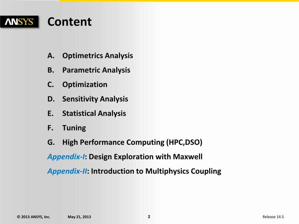
A. Optimetrics Analysis
B. Parametric Analysis
C. Optimization
D. Sensitivity Analysis
E. Statistical Analysis
F. Tuning
G. High Performance Computing (HPC,DSO)
Appendix-I: Design Exploration with Maxwell
Appendix-II: Introduction to Multiphysics Coupling
Content
© 2013 ANSYS, Inc. May 21, 2013 3 Release 14.5
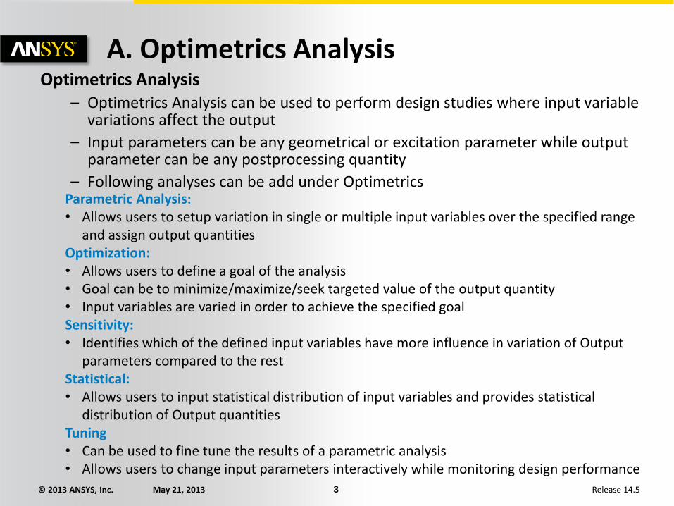
A. Optimetrics Analysis Optimetrics Analysis
– Optimetrics Analysis can be used to perform design studies where input variable variations affect the output
– Input parameters can be any geometrical or excitation parameter while output parameter can be any postprocessing quantity
– Following analyses can be add under Optimetrics
Parametric Analysis: • Allows users to setup variation in single or multiple input variables over the specified range
and assign output quantities Optimization: • Allows users to define a goal of the analysis • Goal can be to minimize/maximize/seek targeted value of the output quantity • Input variables are varied in order to achieve the specified goal Sensitivity: • Identifies which of the defined input variables have more influence in variation of Output
parameters compared to the rest Statistical: • Allows users to input statistical distribution of input variables and provides statistical
distribution of Output quantities Tuning • Can be used to fine tune the results of a parametric analysis • Allows users to change input parameters interactively while monitoring design performance
© 2013 ANSYS, Inc. May 21, 2013 4 Release 14.5
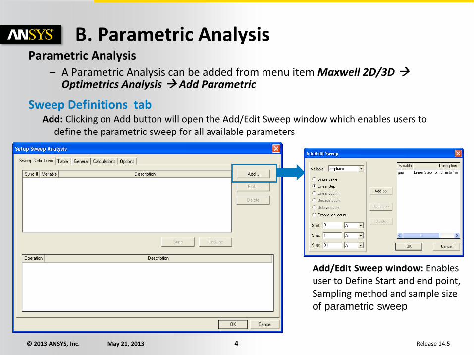
B. Parametric Analysis Parametric Analysis
– A Parametric Analysis can be added from menu item Maxwell 2D/3D Optimetrics Analysis Add Parametric
Sweep Definitions tab Add: Clicking on Add button will open the Add/Edit Sweep window which enables users to
define the parametric sweep for all available parameters
Add/Edit Sweep window: Enables user to Define Start and end point, Sampling method and sample size of parametric sweep
© 2013 ANSYS, Inc. May 21, 2013 5 Release 14.5
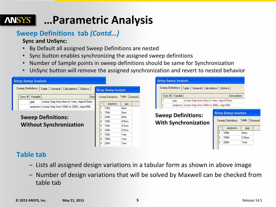
…Parametric Analysis Sweep Definitions tab (Contd…)
Sync and UnSync: • By Default all assigned Sweep Definitions are nested • Sync button enables synchronizing the assigned sweep definitions • Number of Sample points in sweep definitions should be same for Synchronization • UnSync button will remove the assigned synchronization and revert to nested behavior
Sweep Definitions: Without Synchronization
Sweep Definitions: With Synchronization
Table tab
– Lists all assigned design variations in a tabular form as shown in above image
– Number of design variations that will be solved by Maxwell can be checked from table tab
© 2013 ANSYS, Inc. May 21, 2013 6 Release 14.5
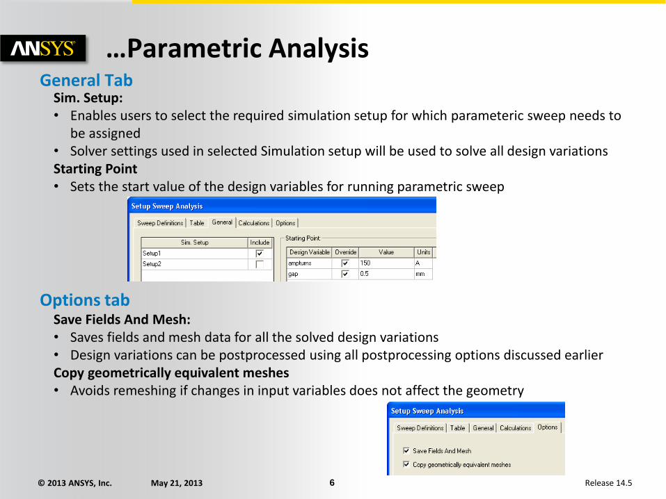
…Parametric Analysis General Tab
Sim. Setup: • Enables users to select the required simulation setup for which parameteric sweep needs to
be assigned • Solver settings used in selected Simulation setup will be used to solve all design variations Starting Point • Sets the start value of the design variables for running parametric sweep
Options tab Save Fields And Mesh: • Saves fields and mesh data for all the solved design variations • Design variations can be postprocessed using all postprocessing options discussed earlier Copy geometrically equivalent meshes • Avoids remeshing if changes in input variables does not affect the geometry
© 2013 ANSYS, Inc. May 21, 2013 7 Release 14.5
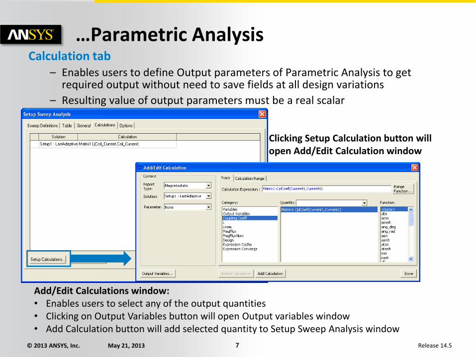
…Parametric Analysis Calculation tab
– Enables users to define Output parameters of Parametric Analysis to get required output without need to save fields at all design variations
– Resulting value of output parameters must be a real scalar
Add/Edit Calculations window: • Enables users to select any of the output quantities • Clicking on Output Variables button will open Output variables window • Add Calculation button will add selected quantity to Setup Sweep Analysis window
Clicking Setup Calculation button will open Add/Edit Calculation window

© 2013 ANSYS, Inc. May 21, 2013 8 Release 14.5
…Parametric Analysis Running Parameteric Analysis
– Right clicking on added Parametric Setup from project Manager tree under Optimetrics and selecting “Analyze”
Examine Results
– Right click on Added parameter setup from Project Manager tree and select “View Analysis Results”
Results can be seen in Tabular or plot view Profile window reports time taken for solving each design variation
© 2013 ANSYS, Inc. May 21, 2013 9 Release 14.5
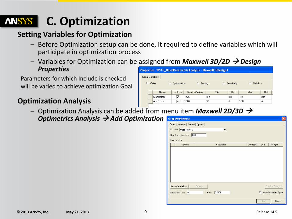
C. Optimization Setting Variables for Optimization
– Before Optimization setup can be done, it required to define variables which will participate in optimization process
– Variables for Optimization can be assigned from Maxwell 3D/2D Design Properties
Optimization Analysis – Optimization Analysis can be added from menu item Maxwell 2D/3D
Optimetrics Analysis Add Optimization
Parameters for which Include is checked will be varied to achieve optimization Goal
© 2013 ANSYS, Inc. May 21, 2013 10 Release 14.5
…Optimization Analysis Goals tab • Optimizers: Sets Optimization algorithm used for analysis
Sequential Nonlinear Programming: • Creates a response surface using a Taylor Series approximation from simulation results • Response surface is used in the optimization loop to determine the gradients and calculate
the next step direction and distance • Numerical noise is assumed to be not significant Sequential Mixed Integer NonLinear Programming: • Equivalent to Sequential Nonlinear Programming algorithm except that Optimization
variable can take only integer values • Can be used where discrete values of optimization are required (eg. Coil turns) Quasi Newton: • Works on the basis of finding a minimum or maximum of a cost function which relates
variables in the model to overall simulation goals • Can be used effectively when numerical noise is less and start values of the optimization
variables are in the vicinity of expected values • Should only be used when 1 or 2 variables are being optimized at a time Pattern Search: • Performs a grid-based simplex search, which makes use of simplices: triangles in 2D space
or tetrahedra in 3D space • Can be used effectively when numerical noise is significant • Takes more iterations to achieve assigned goal
© 2013 ANSYS, Inc. May 21, 2013 11 Release 14.5
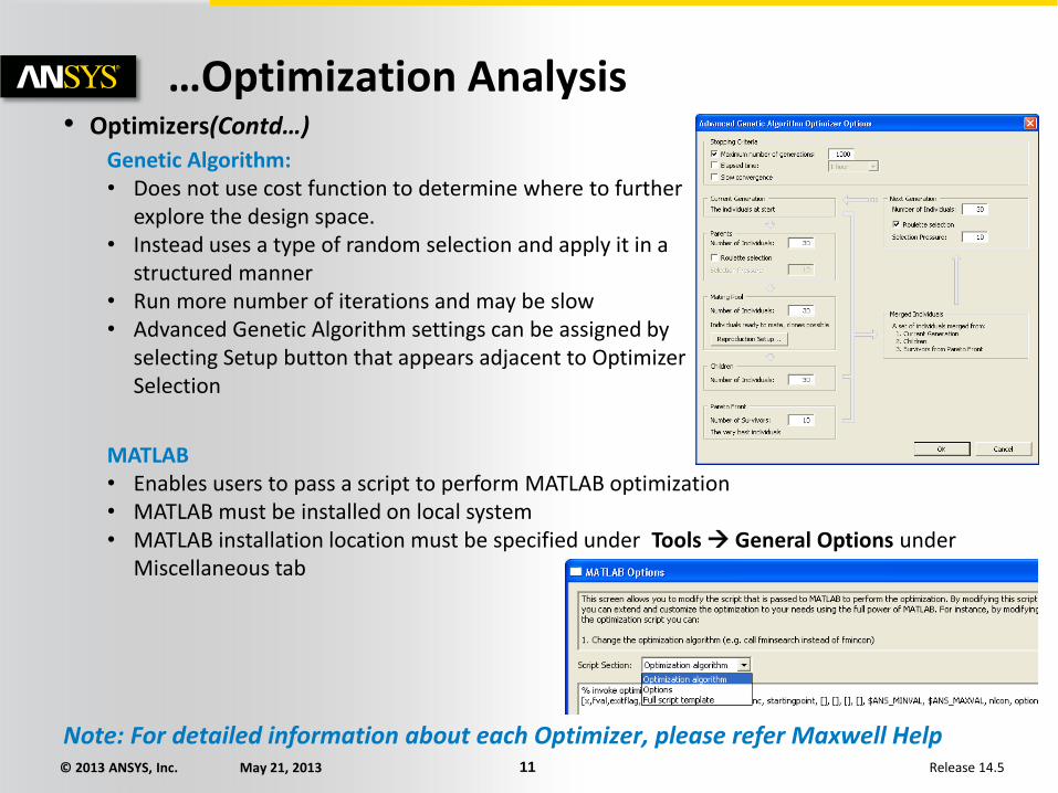
…Optimization Analysis • Optimizers(Contd…)
Genetic Algorithm: • Does not use cost function to determine where to further
explore the design space. • Instead uses a type of random selection and apply it in a
structured manner • Run more number of iterations and may be slow • Advanced Genetic Algorithm settings can be assigned by
selecting Setup button that appears adjacent to Optimizer Selection
MATLAB • Enables users to pass a script to perform MATLAB optimization • MATLAB must be installed on local system • MATLAB installation location must be specified under Tools General Options under
Miscellaneous tab
Note: For detailed information about each Optimizer, please refer Maxwell Help
© 2013 ANSYS, Inc. May 21, 2013 12 Release 14.5
…Optimization Analysis Goals tab (Contd…)
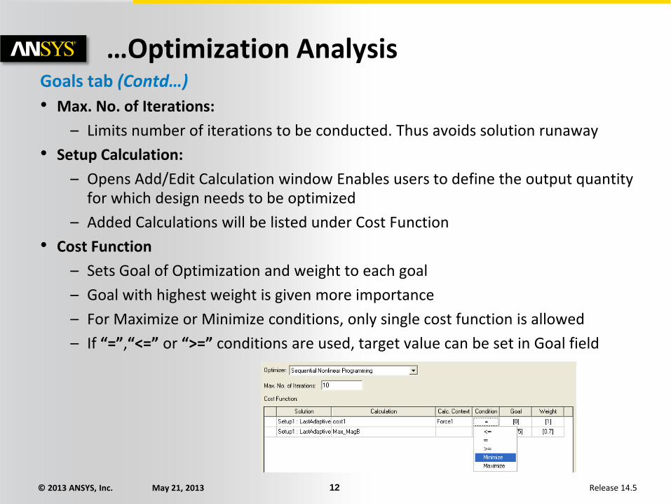
• Max. No. of Iterations:
– Limits number of iterations to be conducted. Thus avoids solution runaway
• Setup Calculation:
– Opens Add/Edit Calculation window Enables users to define the output quantity for which design needs to be optimized
– Added Calculations will be listed under Cost Function
• Cost Function
– Sets Goal of Optimization and weight to each goal
– Goal with highest weight is given more importance
– For Maximize or Minimize conditions, only single cost function is allowed
– If “=”,“<=” or “>=” conditions are used, target value can be set in Goal field
© 2013 ANSYS, Inc. May 21, 2013 13 Release 14.5
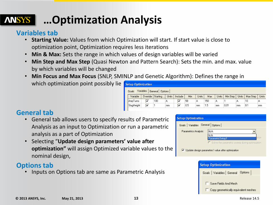
…Optimization Analysis Variables tab
• Starting Value: Values from which Optimization will start. If start value is close to optimization point, Optimization requires less iterations
• Min & Max: Sets the range in which values of design variables will be varied • Min Step and Max Step (Quasi Newton and Pattern Search): Sets the min. and max. value
by which variables will be changed • Min Focus and Max Focus (SNLP, SMINLP and Genetic Algorithm): Defines the range in
which optimization point possibly lie
General tab • General tab allows users to specify results of Parametric
Analysis as an input to Optimization or run a parametric analysis as a part of Optimization
• Selecting “Update design parameters’ value after optimization” will assign Optimized variable values to the nominal design,
Options tab • Inputs on Options tab are same as Parametric Analysis

© 2013 ANSYS, Inc. May 21, 2013 14 Release 14.5
…Optimization Running Optimization
– Right clicking on added Optimization Setup from project Manager tree under Optimetrics and selecting “Analyze”
Examine Results
– Right click on Added Optimization setup from Project Manager tree and select “View Analysis Results”
Results can be seen in Tabular or plot view Profile window reports time taken for solving each design variation

© 2013 ANSYS, Inc. May 21, 2013 15 Release 14.5
D. Sensitivity Setting Variables for Sensitivity
– Before Sensitivity setup can be done, it required to define variables for sensitivity analysis
– Variables can be assigned from Maxwell 3D/2D Design Properties
Sensitivity Analysis – Sensitivity analysis can be added from menu item Maxwell 2D/3D
Optimetrics Analysis Add Sensitivity
Parameters for which Include is checked will be used in Sensitivity analysis
© 2013 ANSYS, Inc. May 21, 2013 16 Release 14.5
…Sensitivity
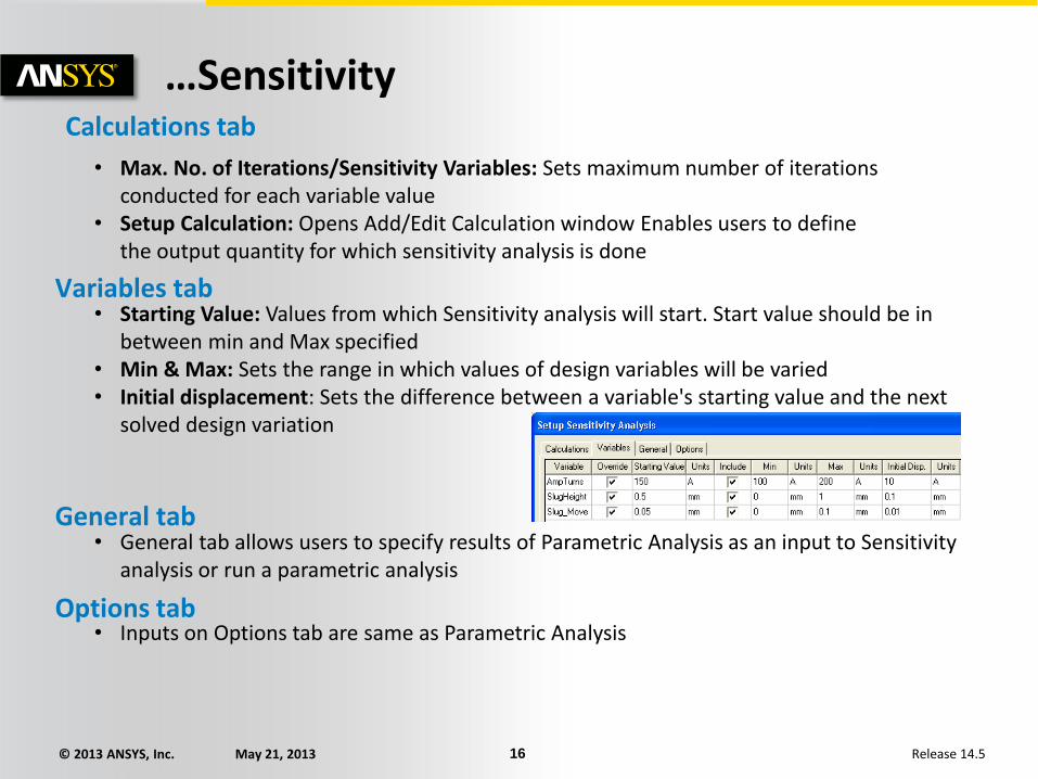
Variables tab • Starting Value: Values from which Sensitivity analysis will start. Start value should be in
between min and Max specified • Min & Max: Sets the range in which values of design variables will be varied • Initial displacement: Sets the difference between a variable's starting value and the next
solved design variation
General tab • General tab allows users to specify results of Parametric Analysis as an input to Sensitivity
analysis or run a parametric analysis
Options tab • Inputs on Options tab are same as Parametric Analysis
Calculations tab
• Max. No. of Iterations/Sensitivity Variables: Sets maximum number of iterations conducted for each variable value
• Setup Calculation: Opens Add/Edit Calculation window Enables users to define the output quantity for which sensitivity analysis is done
© 2013 ANSYS, Inc. May 21, 2013 17 Release 14.5
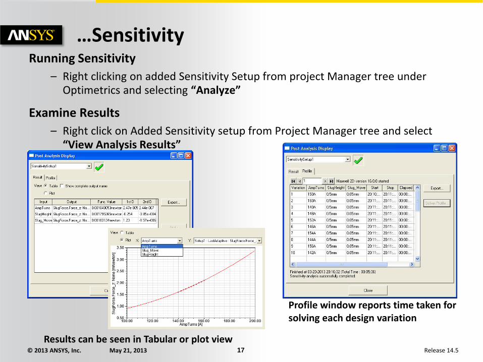
…Sensitivity Running Sensitivity
– Right clicking on added Sensitivity Setup from project Manager tree under Optimetrics and selecting “Analyze”
Examine Results
– Right click on Added Sensitivity setup from Project Manager tree and select “View Analysis Results”
Results can be seen in Tabular or plot view
Profile window reports time taken for solving each design variation

© 2013 ANSYS, Inc. May 21, 2013 18 Release 14.5
E. Statistical Analysis Setting Variables for Sensitivity
– Similar to Sensitivity, Statistical Analysis requires definition of variables for analysis
– In Addition, users can set standard deviation for each variable
– Variables can be assigned from Maxwell 3D/2D Design Properties
Statistical Analysis
– Sensitivity analysis can be added from menu item Maxwell 2D/3D Optimetrics Analysis Add Statistical

© 2013 ANSYS, Inc. May 21, 2013 19 Release 14.5
…Statistical Analysis
Variables tab • Allows users to define, Starting values, Min and Max limits of variables • In addition users can define distribution criteria using Standard deviation or tolerance value
General tab • General tab allows users to specify results of Parametric Analysis as an input to Statistical
analysis or run a parametric analysis
Options tab • Inputs on Options tab are same as Parametric Analysis
Calculations tab • Max. No. of Iterations: Limits Maximum number
of iterations carried out in statistical analysis • Setup Calculation: Opens Add/Edit Calculation
window Enables users to define the output quantity for which statistical analysis is done
© 2013 ANSYS, Inc. May 21, 2013 20 Release 14.5
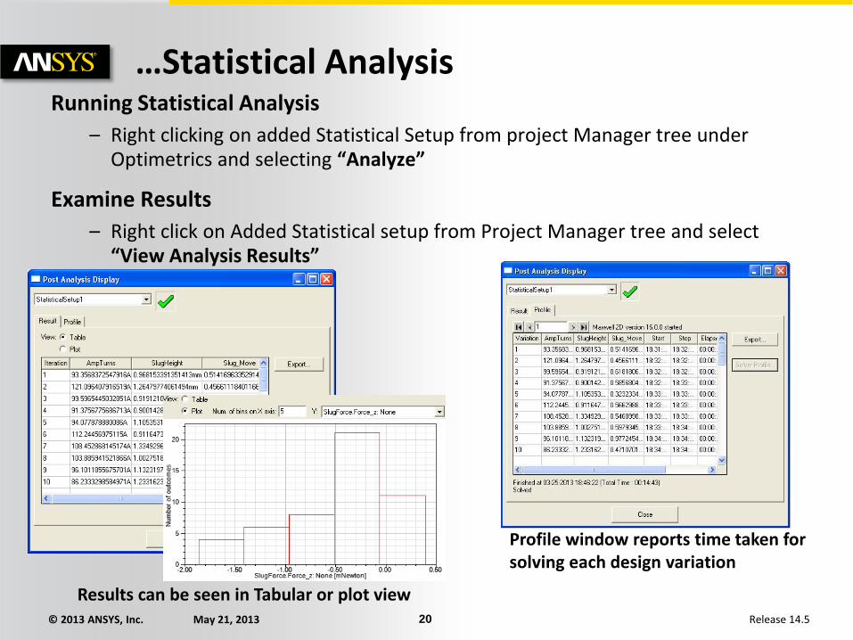
…Statistical Analysis Running Statistical Analysis
– Right clicking on added Statistical Setup from project Manager tree under Optimetrics and selecting “Analyze”
Examine Results
– Right click on Added Statistical setup from Project Manager tree and select “View Analysis Results”
Results can be seen in Tabular or plot view
Profile window reports time taken for solving each design variation
© 2013 ANSYS, Inc. May 21, 2013 21 Release 14.5
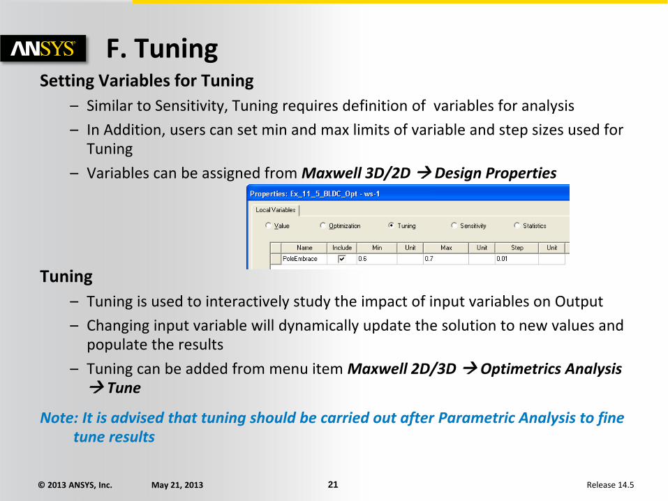
F. Tuning Setting Variables for Tuning
– Similar to Sensitivity, Tuning requires definition of variables for analysis
– In Addition, users can set min and max limits of variable and step sizes used for Tuning
– Variables can be assigned from Maxwell 3D/2D Design Properties
Tuning
– Tuning is used to interactively study the impact of input variables on Output
– Changing input variable will dynamically update the solution to new values and populate the results
– Tuning can be added from menu item Maxwell 2D/3D Optimetrics Analysis Tune
Note: It is advised that tuning should be carried out after Parametric Analysis to fine tune results

© 2013 ANSYS, Inc. May 21, 2013 22 Release 14.5
…Tuning
Browse available variations • Checking this option will make only already solved variation
available in Variations section • This option prohibits solving any new variation using Tuning
Tune • Tune button will tune the results to selected slider position • If solution does not exist for select variation value, Maxwell will compute the results for that
variation
Variations • Variation allow users to dynamically change the design
variables using a slider • Min, Max and step sizes of slider are set from values defined
in Design properties
Untuned Parametric Analysis Results Results after Tuning
© 2013 ANSYS, Inc. May 21, 2013 23 Release 14.5
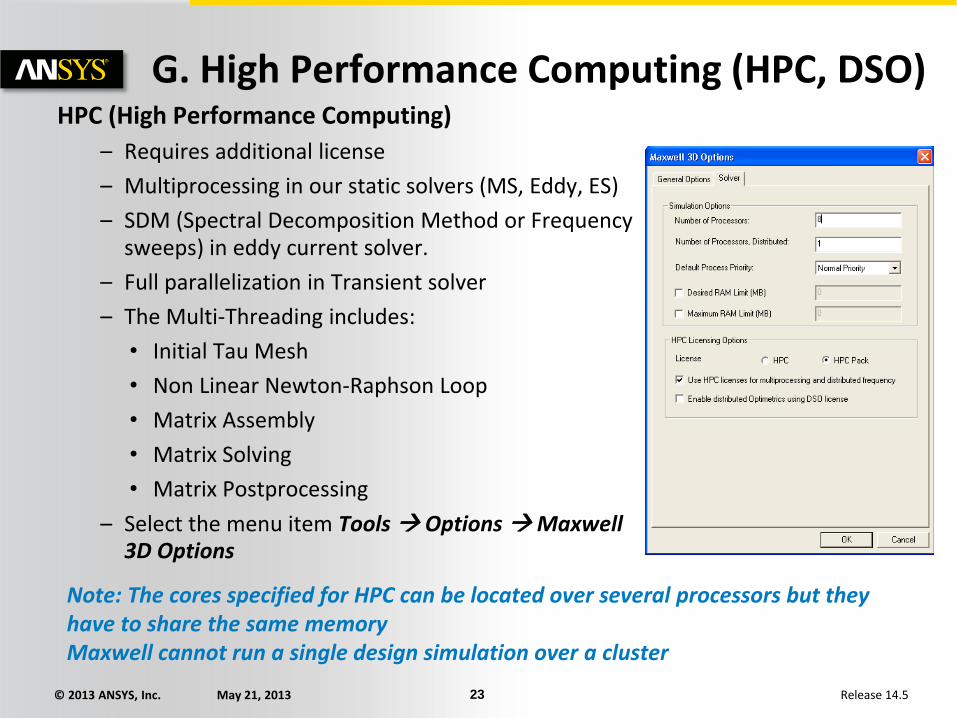
G. High Performance Computing (HPC, DSO) HPC (High Performance Computing)
– Requires additional license
– Multiprocessing in our static solvers (MS, Eddy, ES)
– SDM (Spectral Decomposition Method or Frequency sweeps) in eddy current solver.
– Full parallelization in Transient solver
– The Multi-Threading includes:
• Initial Tau Mesh
• Non Linear Newton-Raphson Loop
• Matrix Assembly
• Matrix Solving
• Matrix Postprocessing
– Select the menu item Tools Options Maxwell 3D Options
Note: The cores specified for HPC can be located over several processors but they have to share the same memory Maxwell cannot run a single design simulation over a cluster
© 2013 ANSYS, Inc. May 21, 2013 24 Release 14.5
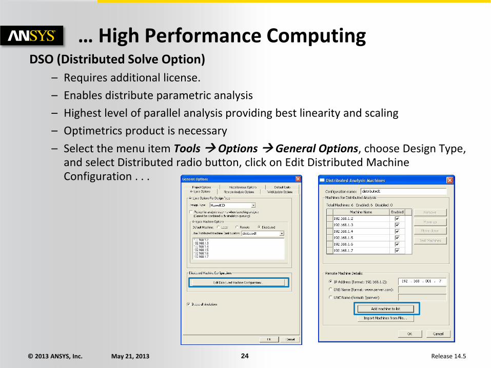
… High Performance Computing DSO (Distributed Solve Option)
– Requires additional license.
– Enables distribute parametric analysis
– Highest level of parallel analysis providing best linearity and scaling
– Optimetrics product is necessary
– Select the menu item Tools Options General Options, choose Design Type, and select Distributed radio button, click on Edit Distributed Machine Configuration . . .

© 2013 ANSYS, Inc. May 21, 2013 25 Release 14.5
APPENDIX-I Design Exploration
© 2013 ANSYS, Inc. May 21, 2013 26 Release 14.5
Using DesignXplorer with Maxwell
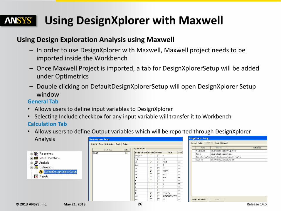
Using Design Exploration Analysis using Maxwell
– In order to use DesignXplorer with Maxwell, Maxwell project needs to be imported inside the Workbench
– Once Maxwell Project is imported, a tab for DesignXplorerSetup will be added under Optimetrics
– Double clicking on DefaultDesignXplorerSetup will open DesignXplorer Setup window
General Tab • Allows users to define input variables to DesignXplorer • Selecting Include checkbox for any input variable will transfer it to Workbench Calculation Tab • Allows users to define Output variables which will be reported through DesignXplorer
Analysis
© 2013 ANSYS, Inc. May 21, 2013 27 Release 14.5
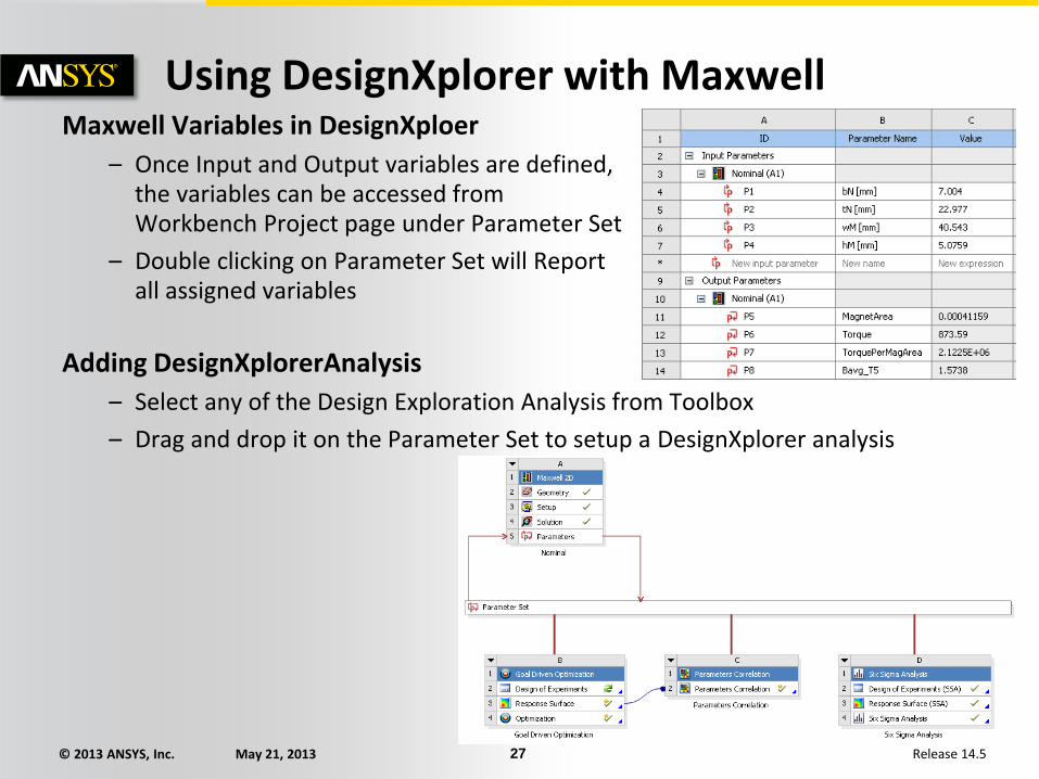
Using DesignXplorer with Maxwell Maxwell Variables in DesignXploer
– Once Input and Output variables are defined, the variables can be accessed from Workbench Project page under Parameter Set
– Double clicking on Parameter Set will Report all assigned variables
Adding DesignXplorerAnalysis
– Select any of the Design Exploration Analysis from Toolbox
– Drag and drop it on the Parameter Set to setup a DesignXplorer analysis
© 2013 ANSYS, Inc. May 21, 2013 28 Release 14.5
APPENDIX-II Introduction to Multiphysics Coupling
© 2013 ANSYS, Inc. May 21, 2013 29 Release 14.5
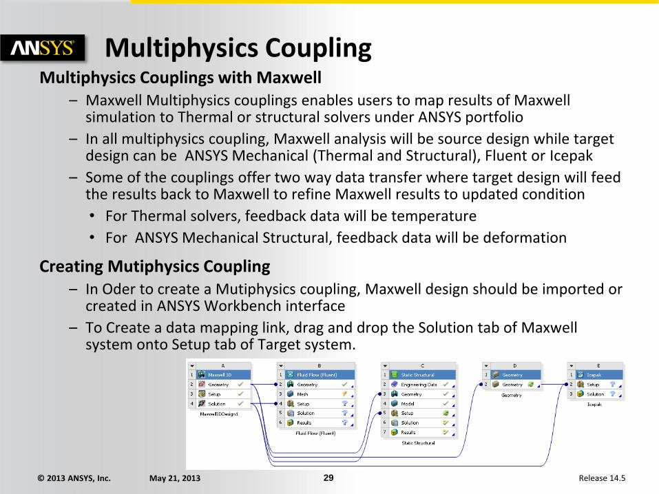
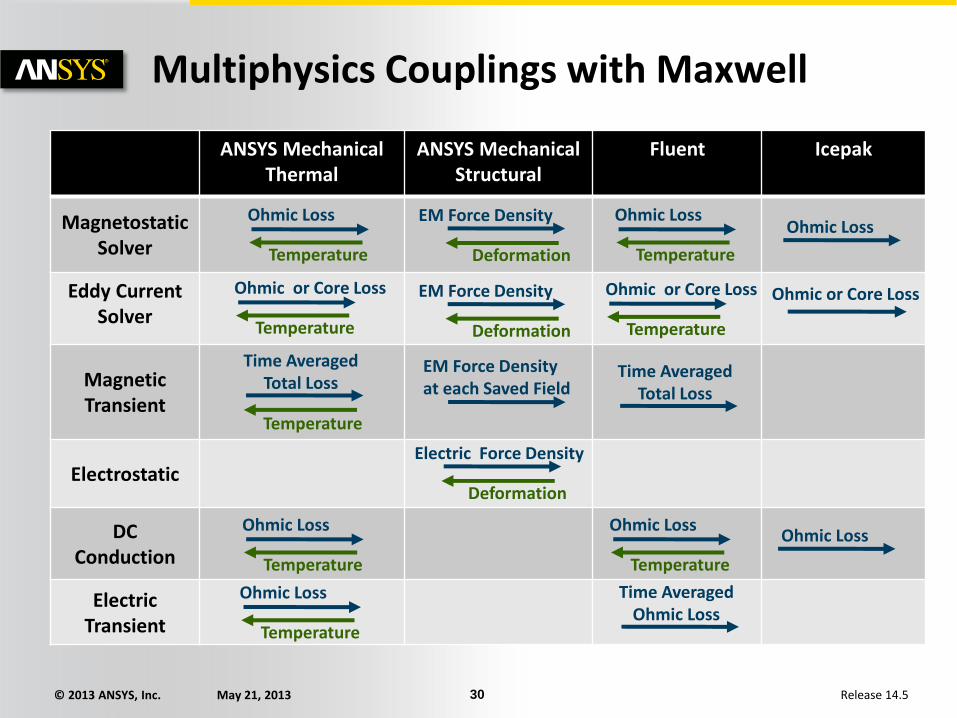
Multiphysics Coupling Multiphysics Couplings with Maxwell
– Maxwell Multiphysics couplings enables users to map results of Maxwell simulation to Thermal or structural solvers under ANSYS portfolio
– In all multiphysics coupling, Maxwell analysis will be source design while target design can be ANSYS Mechanical (Thermal and Structural), Fluent or Icepak
– Some of the couplings offer two way data transfer where target design will feed the results back to Maxwell to refine Maxwell results to updated condition
• For Thermal solvers, feedback data will be temperature
• For ANSYS Mechanical Structural, feedback data will be deformation
Creating Mutiphysics Coupling – In Oder to create a Mutiphysics coupling, Maxwell design should be imported or
created in ANSYS Workbench interface
– To Create a data mapping link, drag and drop the Solution tab of Maxwell system onto Setup tab of Target system.
© 2013 ANSYS, Inc. May 21, 2013 30 Release 14.5
Multiphysics Couplings with Maxwell
ANSYS Mechanical Thermal
ANSYS Mechanical Structural
Fluent Icepak
Magnetostatic Solver
Eddy Current Solver
Magnetic Transient
Electrostatic
DC Conduction
Electric Transient
Ohmic Loss
Temperature
EM Force Density
Deformation
Ohmic Loss
Time Averaged Total Loss
Temperature
EM Force Density at each Saved Field
Time Averaged Total Loss
EM Force Density
Deformation
Ohmic or Core Loss
Temperature
Ohmic or Core Loss
Temperature
Ohmic Loss
Temperature
Ohmic or Core Loss
Electric Force Density
Deformation
Ohmic Loss
Temperature
Ohmic Loss Ohmic Loss
Temperature
Ohmic Loss
Temperature
Time Averaged Ohmic Loss
© 2013 ANSYS, Inc. May 21, 2013 31 Release 14.5
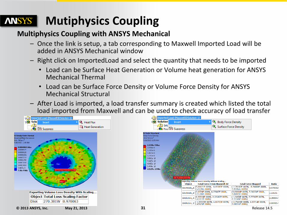
Mutiphysics Coupling Multiphysics Coupling with ANSYS Mechanical
– Once the link is setup, a tab corresponding to Maxwell Imported Load will be added in ANSYS Mechanical window
– Right click on ImportedLoad and select the quantity that needs to be imported
• Load can be Surface Heat Generation or Volume heat generation for ANSYS Mechanical Thermal
• Load can be Surface Force Density or Volume Force Density for ANSYS Mechanical Structural
– After Load is imported, a load transfer summary is created which listed the total load imported from Maxwell and can be used to check accuracy of load transfer
© 2013 ANSYS, Inc. May 21, 2013 32 Release 14.5
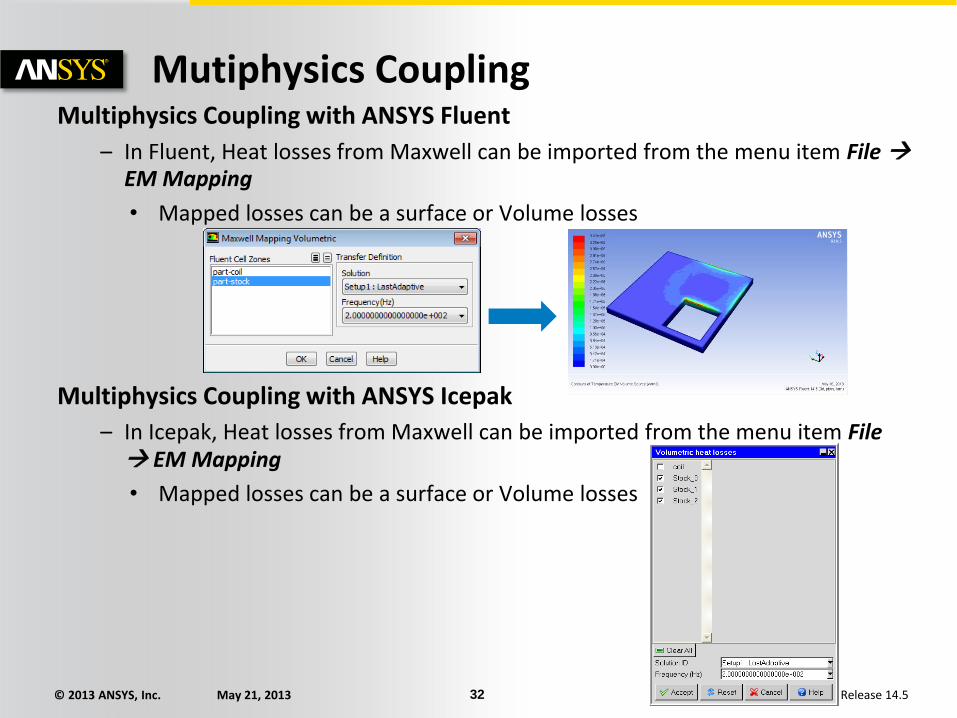
Mutiphysics Coupling Multiphysics Coupling with ANSYS Fluent
– In Fluent, Heat losses from Maxwell can be imported from the menu item File EM Mapping
• Mapped losses can be a surface or Volume losses
Multiphysics Coupling with ANSYS Icepak
– In Icepak, Heat losses from Maxwell can be imported from the menu item File EM Mapping
• Mapped losses can be a surface or Volume losses
© 2013 ANSYS, Inc. May 21, 2013 33 Release 14.5
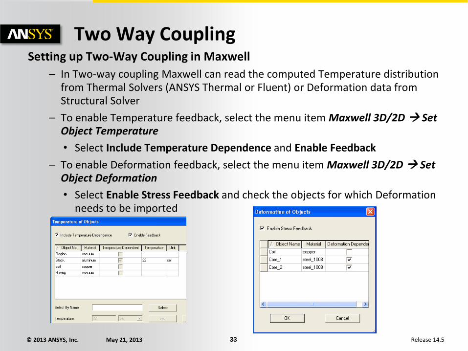
Two Way Coupling Setting up Two-Way Coupling in Maxwell
– In Two-way coupling Maxwell can read the computed Temperature distribution from Thermal Solvers (ANSYS Thermal or Fluent) or Deformation data from Structural Solver
– To enable Temperature feedback, select the menu item Maxwell 3D/2D Set Object Temperature
• Select Include Temperature Dependence and Enable Feedback
– To enable Deformation feedback, select the menu item Maxwell 3D/2D Set Object Deformation
• Select Enable Stress Feedback and check the objects for which Deformation needs to be imported
© 2013 ANSYS, Inc. May 21, 2013 34 Release 14.5
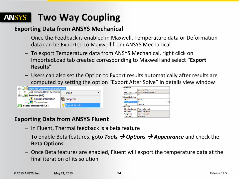
Two Way Coupling Exporting Data from ANSYS Mechanical
– Once the Feedback is enabled in Maxwell, Temperature data or Deformation data can be Exported to Maxwell from ANSYS Mechanical
– To export Temperature data from ANSYS Mechanical, right click on ImportedLoad tab created corresponding to Maxwell and select “Export Results”
– Users can also set the Option to Export results automatically after results are computed by setting the option “Export After Solve” in details view window
Exporting Data from ANSYS Fluent
– In Fluent, Thermal feedback is a beta feature
– To enable Beta features, goto Tools Options Appearance and check the Beta Options
– Once Beta features are enabled, Fluent will export the temperature data at the final iteration of its solution
© 2013 ANSYS, Inc. May 21, 2013 35 Release 14.5
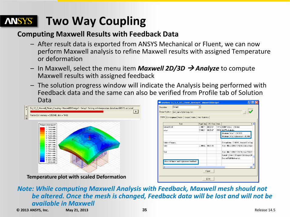
Two Way Coupling Computing Maxwell Results with Feedback Data
– After result data is exported from ANSYS Mechanical or Fluent, we can now perform Maxwell analysis to refine Maxwell results with assigned Temperature or deformation
– In Maxwell, select the menu item Maxwell 2D/3D Analyze to compute Maxwell results with assigned feedback
– The solution progress window will indicate the Analysis being performed with Feedback data and the same can also be verified from Profile tab of Solution Data
Note: While computing Maxwell Analysis with Feedback, Maxwell mesh should not be altered. Once the mesh is changed, Feedback data will be lost and will not be available in Maxwell
Temperature plot with scaled Deformation