Embed Size (px)
Citation preview
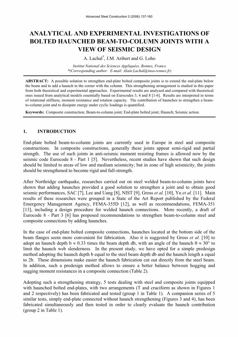
Advanced Steel Construction 2 (2006) 137-160
ANALYTICAL AND EXPERIMENTAL INVESTIGATIONS OF BOLTED HAUNCHED BEAM-TO-COLUMN JOINTS WITH A
VIEW OF SEISMIC DESIGN A. Lachal*, J.M. Aribert and G. Loho
Institut National des Sciences Appliquées, Rennes, France *(Corresponding author: E-mail: [email protected])
ABSTRACT: A possible solution to strengthen end-plate bolted composite joints is to extend the end-plate below the beam and to add a haunch in the corner with the column. This strengthening arrangement is studied in this paper from both theoretical and experimental approaches. Experimental results are analysed and compared with theoretical ones issued from analytical models essentially based on Eurocodes 3, 4 and 8 [1-6]. Results are interpreted in terms of rotational stiffness, moment resistance and rotation capacity. The contribution of haunches to strengthen a beam-to-column joint and to dissipate energy under cyclic loadings is quantified.
Keywords: Composite construction; Beam-to-column joint; End-plate bolted joint; Haunch; Seismic action.
1. INTRODUCTION
End-plate bolted beam-to-column joints are currently used in Europe in steel and composite constructions. In composite constructions, generally these joints appear semi-rigid and partial strength. The use of such joints in anti-seismic moment resisting frames is allowed now by the seismic code Eurocode 8 - Part 1 [5]. Nevertheless, recent studies have shown that such design should be limited to areas of low and medium seismicity; but in zone of high seismicity, the joints should be strengthened to become rigid and full-strength.
After Northridge earthquake, researches carried out on steel welded beam-to-column joints have shown that adding haunches provided a good solution to strengthen a joint and to obtain good seismic performances, SAC [7], Lee and Uang [8], NIST [9], Gross et al. [10], Yu et al. [11]. Main results of these researches were grouped in a State of the Art Report published by the Federal Emergency Management Agency, FEMA-355D [12], as well as recommendations, FEMA-351 [13], including a design procedure for welded haunch connections. More recently, a draft of Eurocode 8 - Part 3 [6] has proposed recommendations to strengthen beam-to-column steel and composite connections by adding haunches.
In the case of end-plate bolted composite connections, haunches located at the bottom side of the beam flanges seem more convenient for fabrication. Also it is suggested by Gross et al. [10] to adopt an haunch depth b 0.33 times the beam depth db, with an angle of the haunch 30° to limit the haunch web slenderness. In the present study, we have opted for a simple predesign method adopting the haunch depth b equal to the steel beam depth db and the haunch length a equal to 2b. These dimensions make easier the haunch fabrication cut out directly from the steel beam. In addition, such a predesign method allows to ensure a better balance between hogging and sagging moment resistances in a composite connection (Table 2).
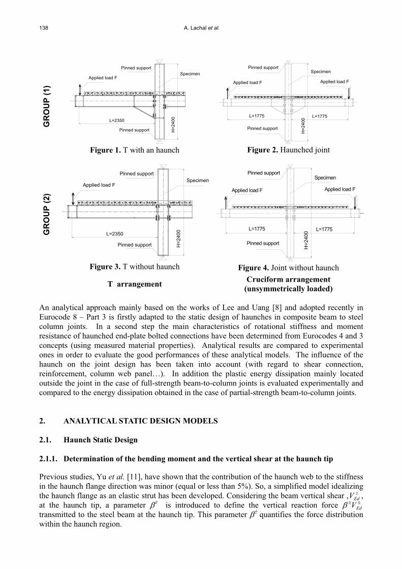
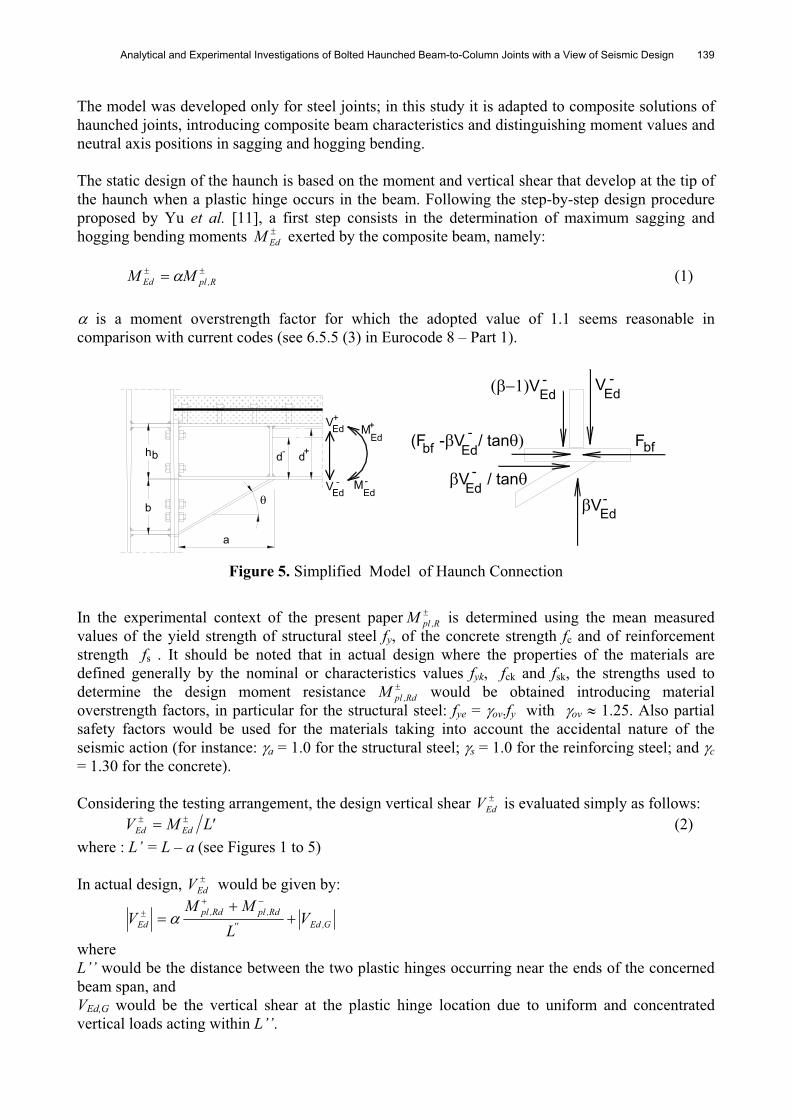
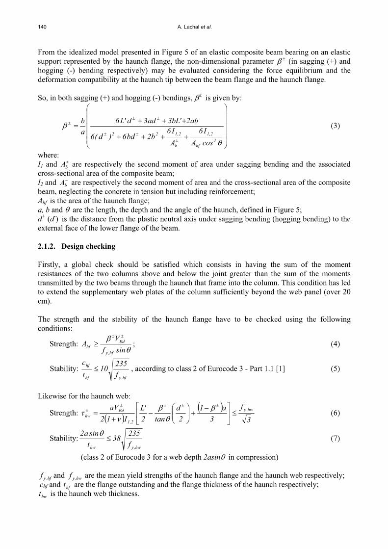
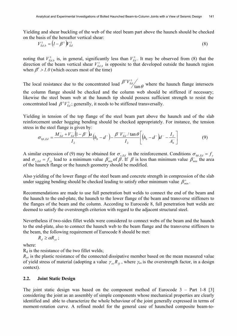
Adopting such a strengthening strategy, 5 tests dealing with steel and composite joints equipped with haunched bolted end-plates, with two arrangements (T and cruciform as shown in Figures 1 and 2 respectively) has been fabricated and tested (group 1 in Table 1). A companion series of 5 similar tests, simply end-plate connected without haunch strengthening (Figures 3 and 4), has been fabricated simultaneously and then tested in order to clearly evaluate the haunch contribution (group 2 in Table 1).
138 A. Lachal et al.
GR
OU
P (1
)
L=2350
Pinned support
Applied load F
Pinned support
H=2
400
Specimen
Figure 1. T with an haunch
L=1775L=1775
Applied load F
H=2
400
Pinned support
Pinned supportSpecimen
Applied load F
Figure 2. Haunched joint
GR
OU
P (2
)
L=2350
Pinned support
Applied load F
Pinned supportH
=240
0Specimen
Figure 3. T without haunch
L=1775L=1775
Applied load F
H=2
400
Pinned support
Pinned supportSpecimen
Applied load F
Figure 4. Joint without haunch
T arrangement Cruciform arrangement(unsymmetrically loaded)
An analytical approach mainly based on the works of Lee and Uang [8] and adopted recently in Eurocode 8 – Part 3 is firstly adapted to the static design of haunches in composite beam to steel column joints. In a second step the main characteristics of rotational stiffness and moment resistance of haunched end-plate bolted connections have been determined from Eurocodes 4 and 3 concepts (using measured material properties). Analytical results are compared to experimental ones in order to evaluate the good performances of these analytical models. The influence of the haunch on the joint design has been taken into account (with regard to shear connection, reinforcement, column web panel…). In addition the plastic energy dissipation mainly located outside the joint in the case of full-strength beam-to-column joints is evaluated experimentally and compared to the energy dissipation obtained in the case of partial-strength beam-to-column joints.
2. ANALYTICAL STATIC DESIGN MODELS
2.1. Haunch Static Design
2.1.1. Determination of the bending moment and the vertical shear at the haunch tip
Previous studies, Yu et al. [11], have shown that the contribution of the haunch web to the stiffness in the haunch flange direction was minor (equal or less than 5%). So, a simplified model idealizing the haunch flange as an elastic strut has been developed. Considering the beam vertical shear , EdV ,at the haunch tip, a parameter is introduced to define the vertical reaction force EdVtransmitted to the steel beam at the haunch tip. This parameter quantifies the force distribution within the haunch region.
Analytical and Experimental Investigations of Bolted Haunched Beam-to-Column Joints with a View of Seismic Design 139
The model was developed only for steel joints; in this study it is adapted to composite solutions of haunched joints, introducing composite beam characteristics and distinguishing moment values and neutral axis positions in sagging and hogging bending.
The static design of the haunch is based on the moment and vertical shear that develop at the tip of the haunch when a plastic hinge occurs in the beam. Following the step-by-step design procedure proposed by Yu et al. [11], a first step consists in the determination of maximum sagging and hogging bending moments EdM exerted by the composite beam, namely:
R,plEd MM (1)
is a moment overstrength factor for which the adopted value of 1.1 seems reasonable in comparison with current codes (see 6.5.5 (3) in Eurocode 8 – Part 1).
dhb
b
a
MEd+Ed
+V
-MEdVEd
-
d+-
-EdV
bfFbf(F - V / tan
-EdV
VEd -
Ed
EdV / tan -
-
Figure 5. Simplified Model of Haunch Connection
In the experimental context of the present paper R,plM is determined using the mean measured values of the yield strength of structural steel fy, of the concrete strength fc and of reinforcement strength fs . It should be noted that in actual design where the properties of the materials are defined generally by the nominal or characteristics values fyk, fck and fsk, the strengths used to determine the design moment resistance Rd,plM would be obtained introducing material overstrength factors, in particular for the structural steel: fye = ov.fy with ov 1.25. Also partial safety factors would be used for the materials taking into account the accidental nature of the seismic action (for instance: a = 1.0 for the structural steel; s = 1.0 for the reinforcing steel; and c= 1.30 for the concrete).
Considering the testing arrangement, the design vertical shear EdV is evaluated simply as follows: 'LMV EdEd (2)
where : L’ = L – a (see Figures 1 to 5)
In actual design, EdV would be given by:
G,Ed''Rd,plRd,pl
Ed VL
MMV
whereL’’ would be the distance between the two plastic hinges occurring near the ends of the concerned beam span, and VEd,G would be the vertical shear at the plastic hinge location due to uniform and concentrated vertical loads acting within L’’.
140 A. Lachal et al.
From the idealized model presented in Figure 5 of an elastic composite beam bearing on an elastic support represented by the haunch flange, the non-dimensional parameter (in sagging (+) and hogging (-) bending respectively) may be evaluated considering the force equilibrium and the deformation compatibility at the haunch tip between the beam flange and the haunch flange.
So, in both sagging (+) and hogging (-) bendings, is given by:
3hf
2,1
b
2,122
cosAI6
AI6
b2bd6)d(6
ab2'bL3ad3d'L6ab (3)
where:I1 and bA are respectively the second moment of area under sagging bending and the associated cross-sectional area of the composite beam; I2 and bA are respectively the second moment of area and the cross-sectional area of the composite beam, neglecting the concrete in tension but including reinforcement; Ahf is the area of the haunch flange; a, b and are the length, the depth and the angle of the haunch, defined in Figure 5; d+ (d-) is the distance from the plastic neutral axis under sagging bending (hogging bending) to the external face of the lower flange of the beam.
2.1.2. Design checking
Firstly, a global check should be satisfied which consists in having the sum of the moment resistances of the two columns above and below the joint greater than the sum of the moments transmitted by the two beams through the haunch that frame into the column. This condition has led to extend the supplementary web plates of the column sufficiently beyond the web panel (over 20 cm).
The strength and the stability of the haunch flange have to be checked using the following conditions:
Strength:sinfV
Ahf,y
Edhf ; (4)
Stability: hf,yhf
hf
f23510
tc
, according to class 2 of Eurocode 3 - Part 1.1 [1] (5)
Likewise for the haunch web:
Strength:3
f3
a12
dtan2
'LI12
aV hw,y
2,1
Edhw (6)
Stability:hw,yhw f
23538tsina2 (7)
(class 2 of Eurocode 3 for a web depth 2asin in compression)
hf,yf and hw,yf are the mean yield strengths of the haunch flange and the haunch web respectively; chf and hft are the flange outstanding and the flange thickness of the haunch respectively; hwt is the haunch web thickness.
Analytical and Experimental Investigations of Bolted Haunched Beam-to-Column Joints with a View of Seismic Design 141
Yielding and shear buckling of the web of the steel beam part above the haunch should be checked on the basis of the hereafter vertical shear:
Edb,Ed V1V (8)
noting that b,EdV is, in general, significantly less than EdV . It may be observed from (8) that the direction of the beam vertical shear b,EdV is opposite to that developed outside the haunch region when 1.0 (which occurs most of the time)
The local resistance due to the concentrated load tanEdV where the haunch flange intersects
the column flange should be checked and the column web should be stiffened if necessary; likewise the steel beam web at the haunch tip should possess sufficient strength to resist the concentrated load EdV ; generally, it needs to be stiffened transversally.
Yielding in tension of the top flange of the steel beam part above the haunch and of the slab reinforcement under hogging bending should be checked appropriately. For instance, the tension stress in the steel flange is given by:
bb
Edb
EdEdEdbft A
IddhI
Vdh
IaVM 2
22,
tan/1(9)
A similar expression of (9) may be obtained for Eds, in the reinforcement. Conditions yEdbft f,and ysEds f, lead to a minimum value min of -. If - is less than minimum value min the area of the haunch flange or the haunch geometry should be modified.
Also yielding of the lower flange of the steel beam and concrete strength in compression of the slab under sagging bending should be checked leading to satisfy other minimum value min .
Recommendations are made to use full penetration butt welds to connect the end of the beam and the haunch to the end-plate, the haunch to the lower flange of the beam and transverse stiffeners to the flanges of the beam and the column. According to Eurocode 8, full penetration butt welds are deemed to satisfy the overstrength criterion with regard to the adjacent structural steel.
Nevertheless if two-sides fillet welds were considered to connect webs of the beam and the haunch to the end-plate, also to connect the haunch web to the beam flange and the transverse stiffeners to the beam, the following requirement of Eurocode 8 should be met:
yed RR ;where:Rd is the resistance of the two fillet welds; Rye is the plastic resistance of the connected dissipative member based on the mean measured value of yield stress of material (adopting a value fyov R , where ov is the overstrength factor, in a design context).
2.2. Joint Static Design
The joint static design was based on the component method of Eurocode 3 – Part 1-8 [3] considering the joint as an assembly of simple components whose mechanical properties are clearly identified and able to characterize the whole behaviour of the joint generally expressed in terms of moment-rotation curve. A refined model for the general case of haunched composite beam-to-
142 A. Lachal et al.
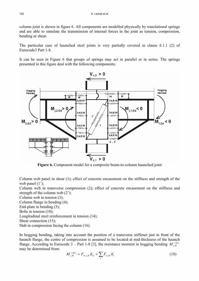
column joint is shown in figure 6. All components are modelled physically by translational springs and are able to simulate the transmission of internal forces in the joint as tension, compression, bending or shear.
The particular case of haunched steel joints is very partially covered in clause 6.1.1 (2) of Eurocode3 Part 1-8.
It can be seen in Figure 6 that groups of springs may act in parallel or in series. The springs presented in this figure deal with the following components:
Figure 6. Component model for a composite beam-to-column haunched joint
Column web panel in shear (1); effect of concrete encasement on the stiffness and strength of the web panel (1’); Column web in transverse compression (2); effect of concrete encasement on the stiffness and strength of the column web (2’); Column web in tension (3); Column flange in bending (4); End-plate in bending (5); Bolts in tension (10); Longitudinal steel reinforcement in tension (14); Shear connection (15); Slab in compression facing the column (16).
In hogging bending, taking into account the position of a transverse stiffener just in front of the haunch flange, the centre of compression is assumed to be located at mid-thickness of the haunch flange. According to Eurocode 3 – Part 1-8 [3], the resistance moment in hogging bending )th(
R,jMmay be determined from:
rrR,trsrR,s,tr
)th(R,j h.Fh.FM (10)
Analytical and Experimental Investigations of Bolted Haunched Beam-to-Column Joints with a View of Seismic Design 143
where:R,trF is the effective design tension resistance of bolt-row r;
R,s,trF is the design tension resistance of a row r of the reinforcing bars included within the effective width of the concrete flange (adopting an effective width )15.0/25.0()4/(b 0eff where 0 is the cantilever span and where 0.25/0.15 is an amplification factor for hogging bending zone in accordance with clause 5.4.1.2 in Eurocode 4.1.1 [4];
srh and rh are the distances from row r of reinforcing bars or bolts to the centre of compression, r is the number of a particular row.
The tension resistance Ftr R of bolt-row r as an individual bolt-row should be taken as the smallest value of the tension resistance for an individual bolt-row of the following basic components: the column web in tension Ft,wc,R, the column flange in bending Ft,fc,R, the end-plate in bending Ft,ep,Rand the beam web or the haunch web in tension Ft,wb,R.Dealing with the bolt-rows closest to the centre of compression, a reduction of their tension resistances may be applied in such a way that:
)V
,F,Fmin(FF R,wpR,fh,cR,wc,c
rR,tR,s,tr (11)
where:R,wc,cF and R,fh,cF are the resistance of the column web in compression and the resistance of the
haunch flange in compression (and partially the web), respectively. Rd,wpV is the plastic shear resistance of the column web panel (of appropriate slenderness) and
is a transformation parameter defined in clause 7.3.3 of Eurocode 3 Part 1-8: 2MM1 Ed,1,jEd,2,j1
2MM1 Ed,2,jEd,1,j2 (12) where:
1 is the value of the transformation parameter for the right-hand side joint ;
2 is the value of the transformation parameter for the left-hand side joint;
Ed,1,jM is the moment applied to the right joint at the load introduction cross section (figure 6);
Ed,2,jM is the moment applied to the left joint at the load introduction cross section (figure 6); In the present study, = 1 for the T joint configuration and 1.5 2.0 for the cruciform one.
Provided that the axial force NSd in the connected member does not exceed 10% of the axial cross-sectional resistance Npl,Rd of its cross-section, the initial rotational stiffness Si,ini of a joint, for a moment Mj,Sd less than the moment resistance Mj,Sd of the joint, may be obtained from:
1
eq21
2eqa
)th(ini,j k
1k1
k1)z(ES (13)
eq
rrr,eff
eq z
hkk ;
rrr,eff
2r
rr,eff
eq hk
)h(kz ;
1
i r,ir,eff k
1k (14)
where:Ea is the modulus of elasticity of steel;
eqz is the equivalent lever arm,
144 A. Lachal et al.
1k is the stiffness coefficient for the column web panel in shear,
2k is the stiffness coefficient for the column web in compression,
eqk is the equivalent stiffness coefficient related to the group of bolt-rows and longitudinal reinforcement in tension (the latter modified by the reduction factor slipk due to the slip effect of the shear connection as given by clause (A5) in Eurocode 4 Part 1-1 [4];
r,effk is the effective stiffness coefficient for layer r; and
r,ik is the stiffness coefficient representing component i relative to layer r;
rh is the distance between layer r and the centre of compression.
In sagging bending, assuming a centre of compression located at the mid-thickness of the concrete slab ( only considering the thickness above the sheeting ribs), expressions similar to the above ones may be adopted, replacing R,wc,cF and R,fb,cF by the bearing resistance R,cF between the slab and the column and introducing a specific stiffness coefficient ck for the slab in compression. More details may be found in Ciutina [14].
rrR,tr
)th(R,j h.FM (15)
1
eqc1
2eq
)th(ini,j k
1k1
k1)Z(ES (16)
Under reversal bending moment, the total force due to the compression of the slab on one side plus the tension of the reinforcement on the other side should be transferred to the column using the resistances of two mechanisms Eurocode 8 - Part 1 (Annex C) [5]:
- a direct compression on the column flange: )f85.0(dbF ceffc1R (17)
where:bc is the column flange width, deff is the thickness of the slab above the ribs of the profiled sheeting for composite slabs
(and overall depth of the slab in case of solid slab);
- a compressed concrete struds inclined to 45° on the column sides: )f85.0(dh7.0F ceffc2R (18)
where hc is the depth of the column steel section. In addition the tension strud model requires a tension-tie cross-sectional area:
sk
2RT f
F5.0A (19)
over a width hc and fully anchored. This area AT is introduced on both sides of the column to account for reversal of bending moments
The resistance offered by the two mechanisms is given by: 2R1RR,c FFF (20)
It is to point out that the presence of haunch in a beam to column connection creates an enlarged panel zone. The distribution of internal forces in a such enlarged panel zone is different from that of

Analytical and Experimental Investigations of Bolted Haunched Beam-to-Column Joints with a View of Seismic Design 145
the single panel zone (without haunch). Lee and Uang [8] for welded beam-to-column joint and on the basis of results of finite element analysis and available full-scale test results have developed an analytical procedure to model the stiffness and strength of an enlarged panel zone. In the case of haunched end-plate bolted composite joints the problem is more complex and has not been investigated yet. In the next future one of the objectives of the authors of this paper is to develop a scientific background about this topic. For want of something better, a simplified checking may be used evaluating the panel shear as follows:
3
fA9.0
2VV
ZM
ZM
V cw,yvc
1C2C
eq
Ed,1j
eq
Ed,2jEd,wp (21)
whereVC1 and VC2 are the horizontal forces exerted by the column ends (Figure 6) and Avc is the shear area of the column.
3. PRESENTATION OF THE EXPERIMENTAL INVESTIGATION
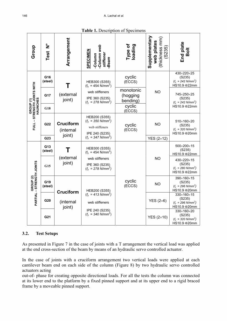
3.1. Program of tests
Completing Figures 1 to 4, Table 1 presents the main characteristics of ten full-scale beam-to-column joints (major axis connections) tested at INSA of Rennes-France. All the specimens include bolted end plate connections, with upper and lower external rows of bolts in the case of steel joints and only lower external bolt row in the case of composite joints. In Table 1, two main Groups of tests may be distinguished:
- Group 1 with full-strength joints with haunches; - Group 2 with partial strength joints without haunches.
Each group comprises steel and composite joints with T and cruciform arrangements, monotonically or cyclically loaded.
For all the tests, as shown in Figures 1 to 4, transverse stiffeners have been welded to the column flanges in the web-panel. Except for test G13, all the bolts were tightened at their nominal preload. All the welds were made by the semi-automatic inert-gas arc method with full penetration butt welds, using E MAG 136 procedure and T46 4 MM2 H5 consumables, according to European norms (EN 287 and EN 288).
For all the composite specimens (except G18), common characteristics are a full shear connection with welded headed studs = 19 mm (h = 80 mm or 100 mm) and , a composite slab (cast on a steel sheeting COFRASTRA 40) whose cross-section of dimensions 120 1000mm is reinforced by 10 longitudinal rebars 10 mm and by transverse rebars 10 mm spaced each 10 cm, with 2 additional transverse rebars near the column flanges to ensure a strut-tie action according to (19).
Although the main objective of the present research is the effect of joint strengthening on the joint seismic performances by introducing haunches, other parameters are considered as the performance of the composite solution in comparison with the steel one (for that, steel reference tests have been performed prior each series of composite tests; i.e. G13, G16 and G19 in comparison with G15, G18 and G20 respectively. The contribution of the column web panel to the global performance of the joint is also analysed.
146 A. Lachal et al.
Table 1. Description of Specimens G
roup
Test
N°
Arr
ange
men
t
SPEC
IMEN
-Col
umn
-Col
umn
web
st
iffen
er-B
eam
Type
of
load
ing
Supp
lem
enta
ryw
eb p
late
s (th
ickn
ess
mm
) (S
235)
End
plat
eB
olt
G16(steel)
cyclic(ECCS)
430 220 25(S235)
(fy = 242 N/mm2)HS10.9 22mm
G17monotonic (hoggingbending)
G18
T(external
joint)
HEB300 (S355) (fy = 454 N/mm2)
web stiffeners
IPE 360 (S235) (fy = 278 N/mm2)
cyclic(ECCS)
NO 745 250 25(S235)
(fy = 242 N/mm2)HS10.9 22mm
G22 NO
GR
OU
P (1
) FU
LL –
STR
ENG
TH J
OIN
TS W
ITH
H
AU
NC
HES
G23
Cruciform(internal
joint)
HEB200 (S355) (fy = 350 N/mm2)
web stiffeners
IPE 240 (S235) (fy = 347 N/mm2)
cyclic(ECCS)
YES (2 12)
510 160 20(S235)
(fy = 320 N/mm2)HS10.9 20mm
G13(steel)
500 200 15 (S235)
HS10.9 22mm
G15
T(external
joint)
HEB300 (S355) (fy = 454 N/mm2)
web stiffeners
IPE 360 (S235) (fy = 278 N/mm2)
NO 430 220 15(S235)
(fy = 280 N/mm2)HS10.9 22mm
G19(steel) NO
390 160 15(S235)
(fy = 296 N/mm2)HS10.9 20mm
G20 YES (2 6)330 160 15
(S235)(fy = 296 N/mm2)HS10.9 20mm
GR
OU
P (2
) PA
RTI
AL
– ST
REN
GTH
JO
INTS
G21
Cruciform
(internaljoint)
HEB200 (S355) (fy = 413 N/mm2)
web stiffeners
IPE 240 (S235) (fy = 340 N/mm2)
cyclic(ECCS)
YES (2 10) 330 160 20
(S235)(fy = 320 N/mm2)HS10.9 20mm
3.2. Test Setups
As presented in Figure 7 in the case of joints with a T arrangement the vertical load was applied at the end cross-section of the beam by means of an hydraulic servo controlled actuator.
In the case of joints with a cruciform arrangement two vertical loads were applied at each cantilever beam end on each side of the column (Figure 8) by two hydraulic servo controlled actuators actingout-of- phase for creating opposite directional loads. For all the tests the column was connected at its lower end to the platform by a fixed pinned support and at its upper end to a rigid braced frame by a moveable pinned support.
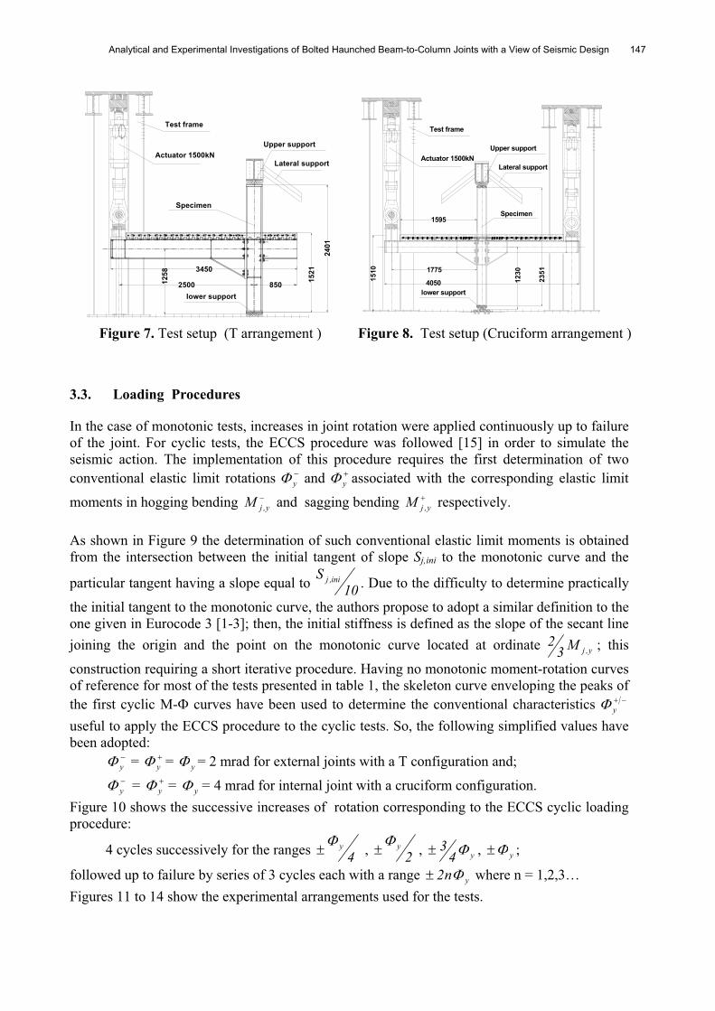
Analytical and Experimental Investigations of Bolted Haunched Beam-to-Column Joints with a View of Seismic Design 147
3450
2401
1521
Lateral support
Upper support
Test frame
Actuator 1500kN
Specimen
lower support2500 85012
58
Figure 7. Test setup (T arrangement )
1510
4050
1595
2351
1230
Upper support
lower support
Lateral support Actuator 1500kN
Test frame
Specimen
1775
Figure 8. Test setup (Cruciform arrangement )
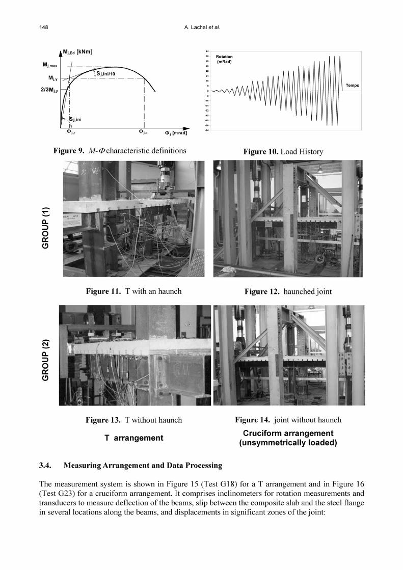
3.3. Loading Procedures
In the case of monotonic tests, increases in joint rotation were applied continuously up to failure of the joint. For cyclic tests, the ECCS procedure was followed [15] in order to simulate the seismic action. The implementation of this procedure requires the first determination of two conventional elastic limit rotations y and y associated with the corresponding elastic limit
moments in hogging bending y,jM and sagging bending y,jM respectively.
As shown in Figure 9 the determination of such conventional elastic limit moments is obtained from the intersection between the initial tangent of slope Sj,ini to the monotonic curve and the
particular tangent having a slope equal to 10S ini,j . Due to the difficulty to determine practically
the initial tangent to the monotonic curve, the authors propose to adopt a similar definition to the one given in Eurocode 3 [1-3]; then, the initial stiffness is defined as the slope of the secant line joining the origin and the point on the monotonic curve located at ordinate y,jM3
2 ; this
construction requiring a short iterative procedure. Having no monotonic moment-rotation curves of reference for most of the tests presented in table 1, the skeleton curve enveloping the peaks of the first cyclic M- curves have been used to determine the conventional characteristics y
useful to apply the ECCS procedure to the cyclic tests. So, the following simplified values have been adopted:
y = y = y = 2 mrad for external joints with a T configuration and;
y = y = y = 4 mrad for internal joint with a cruciform configuration. Figure 10 shows the successive increases of rotation corresponding to the ECCS cyclic loading procedure:
4 cycles successively for the ranges 4y , 2
y , y43 , y ;
followed up to failure by series of 3 cycles each with a range yn2 where n = 1,2,3… Figures 11 to 14 show the experimental arrangements used for the tests.
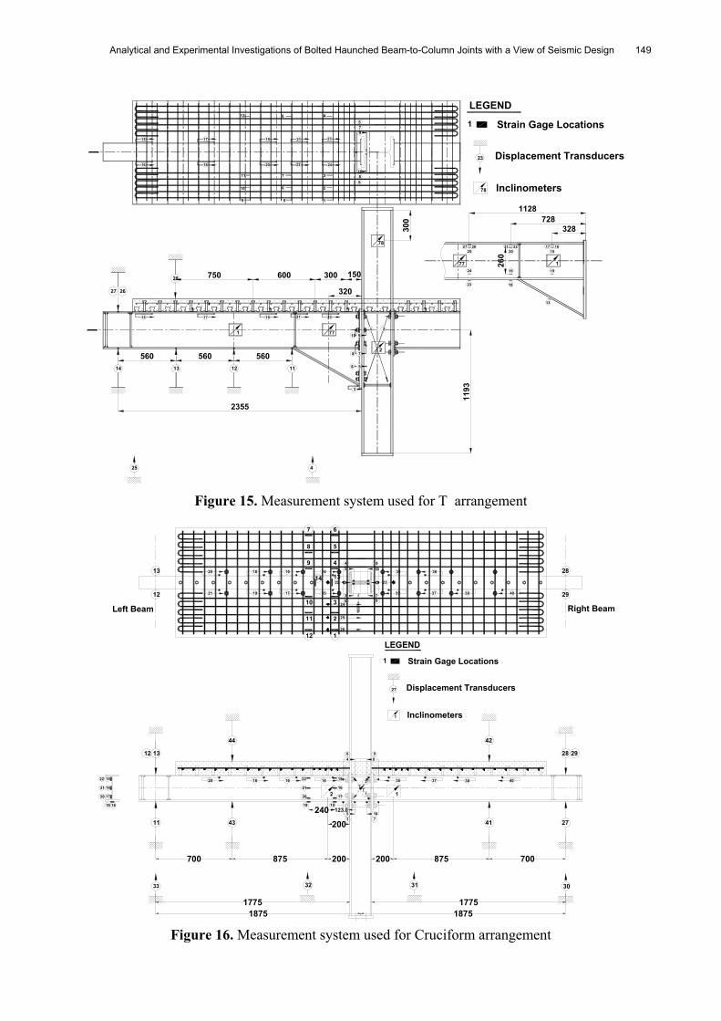
Analytical and Experimental Investigations of Bolted Haunched Beam-to-Column Joints with a View of Seismic Design 149
4
300
1193
150300600750
25
78
23
9
10
7
8
412 8
3
2
1
11
10
9
7
6
5
560 560 56014 13
1
12 11
77
320
910
6
8
5
21
72
21191715
15 17 19 21 23
16 18 20 22 24
5
6
2355
27 26
28
77
18
19
20
260
19
1
2221 17 1626271525
24
23
13
328728
1128
LEGEND
Inclinometers
Displacement Transducers
Strain Gage Locations
78
23
1
Figure 15. Measurement system used for T arrangement
33
27
7
200
123.0240
100
13
12
28
29
32
43
31 30
11 41 27
2928
4244
12 13
7
8
6
5
49
10
11
12
3
2
1
22 15
1621
20 17
19 18
22
21
20
19
15
16
17
18
53 7
10
1
214
64
98
3520 1618 37
21
20
19 17
1618
15
14
22
36
24
45
810
79
34
23
35 37
36
38 40
14 13
25
26
1
700875200
1875
875700 200
177517751875
Right BeamLeft Beam
38 40
Strain Gage Locations
Inclinometers
Displacement Transducers
1
LEGEND
1
27
Figure 16. Measurement system used for Cruciform arrangement
150 A. Lachal et al.
elongation of bolts, flexural bending of end-plates and column flanges, shear deformation of the column web panel. Strain measurements are made for some tests by means of electric gauges bonded on longitudinal and transversal rebars near the column, in several beam cross-sections near the joint or inside the haunch.
To determine the moment-rotation curves presented later on the following definitions have been considered: - the bending moment Mj applied to the joint is located at the column face, hence given by the product:
Mj = FL (kN.m) (21)
where L is the appropriate lever arm defined in Figures 1 to 4.
- the total joint rotation j, including the connection rotation and the column web panel distortion, is deduced from the difference between the two inclinometers I2 (distinguishing I2L on the left side and I2R on the right side in the case of a cruciform joint) and I1:
j = I2 - I1 (mrad) (22)
For end-plate connections (without haunches) where the beam contribution to the joint rotation is low, inclinometer I2 has been located at a short distance from the column flange, equal to about the half depth of the steel beam. On the contrary, for end-plate connections with haunches, where the joint rotation is due essentially to the beam rotation with the formation of a plastic hinge near the end of the haunch, inclinometer I2 has been located at a distance from the end of the haunch, generally greater or at least equal to the depth of the steel beam. Inclinometer I1 gives the rotation due to the flexural bending of the column. For joints with haunches, a supplementary inclinometer I3 is placed on the beam at mid-length of the haunch; allowing to distinguish the rotation due to the connection connection = (I3 –I1) and the beam rotation beam = (I2 – I3).
A global evaluation of the column web panel distortion can be deduced from the algebraic elongations 1 and 2 of the two diagonal transducers 1 and 2 as follows:
)ab2()(ba 2122 (23)
where a and b are the horizontal and vertical sizes of the web panel.
Other rotations of the connection part have been deduced from elongation measurements of bolt rows, in the longitudinal direction, located on the width of end-plates. These values have been compared to the ones directly measured.
4. EXPERIMENTAL RESULTS AND INTERPRETATION
4.1. Global Results For Rotational Stiffness, Moment Resistance And Rotational Capacity
All the experimental values collected in table 2 are defined at the load-introduction cross-section of the connection, i.e. the interface between end-plate and column flange. Elastic limit moments
(exp)y,jM in sagging bending and (exp)
y,jM in hogging bending, maximum bending moments /(exp)maxM ,
initial rotational stiffnesses /(exp)ini,jS and global ultimate rotations /(exp)
u (adding the joint and beam contributions) have been deduced from monotonic (test G17) or skeleton curves enveloping the peaks of cyclic M curves; as a reminder the exact definitions adopted for these
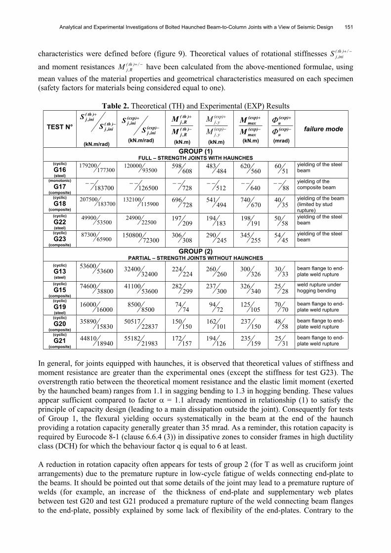
Analytical and Experimental Investigations of Bolted Haunched Beam-to-Column Joints with a View of Seismic Design 151
characteristics were defined before (figure 9). Theoretical values of rotational stiffnesses /)th(ini,jS
and moment resistances /)th(R,jM have been calculated from the above-mentioned formulae, using
mean values of the material properties and geometrical characteristics measured on each specimen (safety factors for materials being considered equal to one).
Table 2. Theoretical (TH) and Experimental (EXP) Results
TEST N° )th(ini,j
)th(ini,j
SS
(kN.m/rad)
(exp)ini,j
(exp)ini,j
SS
(kN.m/rad)
)th(R,j
)th(R,j
MM
(kN.m)
(exp)y,j
(exp)y,j
MM
(kN.m)
(exp)max
(exp)max
MM
(kN.m)
(exp)u
(exp)u
(mrad)
failure mode
GROUP (1) FULL – STRENGTH JOINTS WITH HAUNCHES
(cyclic)
G16(steel)
177300179200
93500120000
608598
484483
560620
5160 yielding of the steel
beam
(monotonic)
G17(composite)
183700 126500 728 512 640 88yielding of the composite beam
(cyclic)
G18(composite)
183700207500
115900132100
728696
494541
670740
3540 yielding of the beam
(limited by stud rupture)
(cyclic)
G22(steel)
5350049900
2250024900
209197
183194
191198
5850 yielding of the steel
beam
(cyclic)
G23(composite)
6590087300
72300150800
308306
245290
255345
4554 yielding of the steel
beam
GROUP (2) PARTIAL – STRENGTH JOINTS WITHOUT HAUNCHES
(cyclic)
G13(steel)
5360053600
3240032400
224224
260260
326300
3330 beam flange to end-
plate weld rupture
(cyclic)
G15(composite)
3880074600
5360041100
299282
300237
340326
2825 weld rupture under
hogging bending
(cyclic)
G19(steel) 16000
160008500
850074
7472
94105
12570
70 beam flange to end-plate weld rupture
(cyclic)
G20(composite) 15830
3589022837
50517150
150101
162150
23758
48 beam flange to end-plate weld rupture
(cyclic)
G21(composite) 18940
4481021983
55182157
172126
194159
23531
25 beam flange to end-plate weld rupture
In general, for joints equipped with haunches, it is observed that theoretical values of stiffness and moment resistance are greater than the experimental ones (except the stiffness for test G23). The overstrength ratio between the theoretical moment resistance and the elastic limit moment (exerted by the haunched beam) ranges from 1.1 in sagging bending to 1.3 in hogging bending. These values appear sufficient compared to factor = 1.1 already mentioned in relationship (1) to satisfy the principle of capacity design (leading to a main dissipation outside the joint). Consequently for tests of Group 1, the flexural yielding occurs systematically in the beam at the end of the haunch providing a rotation capacity generally greater than 35 mrad. As a reminder, this rotation capacity is required by Eurocode 8-1 (clause 6.6.4 (3)) in dissipative zones to consider frames in high ductility class (DCH) for which the behaviour factor q is equal to 6 at least.
A reduction in rotation capacity often appears for tests of group 2 (for T as well as cruciform joint arrangements) due to the premature rupture in low-cycle fatigue of welds connecting end-plate to the beams. It should be pointed out that some details of the joint may lead to a premature rupture of welds (for example, an increase of the thickness of end-plate and supplementary web plates between test G20 and test G21 produced a premature rupture of the weld connecting beam flanges to the end-plate, possibly explained by some lack of flexibility of the end-plates. Contrary to the
Analytical and Experimental Investigations of Bolted Haunched Beam-to-Column Joints with a View of Seismic Design 153
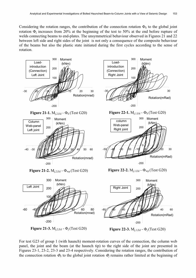
Considering the rotation ranges, the contribution of the connection rotation li to the global joint rotation j increases from 20% at the beginning of the test to 50% at the end before rupture of welds connecting beams to end-plates. The unsymmetrical behaviour observed in Figures 21 and 22 between left side and right sides of the joint is not only a consequence of the composite behaviour of the beams but also the plastic state initiated during the first cycles according to the sense of rotation.
-200
-100
0
100
200
300
-30 -20 -10 0 10 20 30Rotation(mrad)
Moment(kNm)Load-
introduction (Connection)
Left Joint
Figure 21-1. Mj,2,Ed - li (Test G20)
-200
-100
0
100
200
300
-30 -10 10 30
Rotation(mRad)
Moment(kNm)Load-
introduction (Connection)Right Joint
Figure 22-1. Mj,1,Ed - li (Test G20)
-200
-100
0
100
200
300
-40 -30 -20 -10 0 10 20 30 40 50 60
Rotation(mrad)
Moment(kNm) Column
Web-panelLeft joint
Figure 21-2. Mj,2,Ed - wp (Test G20)
-200
-100
0
100
200
300
-50 -40 -30 -20 -10 0 10 20 30
Rotation(mRad)
Moment(kNm) column
Web-panelRight joint
Figure 22-2. Mj,1,Ed - wp (Test G20)
-200
-100
0
100
200
300
-60 -40 -20 0 20 40 60 80Rotation(mrad)
Moment(kNm)
Left Joint
Figure 21-3. Mj,2,Ed - j (Test G20) -200
-100
0
100
200
300
-80 -60 -40 -20 0 20 40 60
Rotation(mRad)
Moment(kNm)
Right Joint
Figure 22-3. Mj,1,Ed - j (Test G20)
For test G23 of group 1 (with haunch) moment-rotation curves of the connection, the column web panel, the joint and the beam (at the haunch tip) to the right side of the joint are presented in Figures 23-1, 23-2, 23-3 and 23-4 respectively. Considering the rotation ranges, the contribution of the connection rotation li to the global joint rotation j remains rather limited at the beginning of
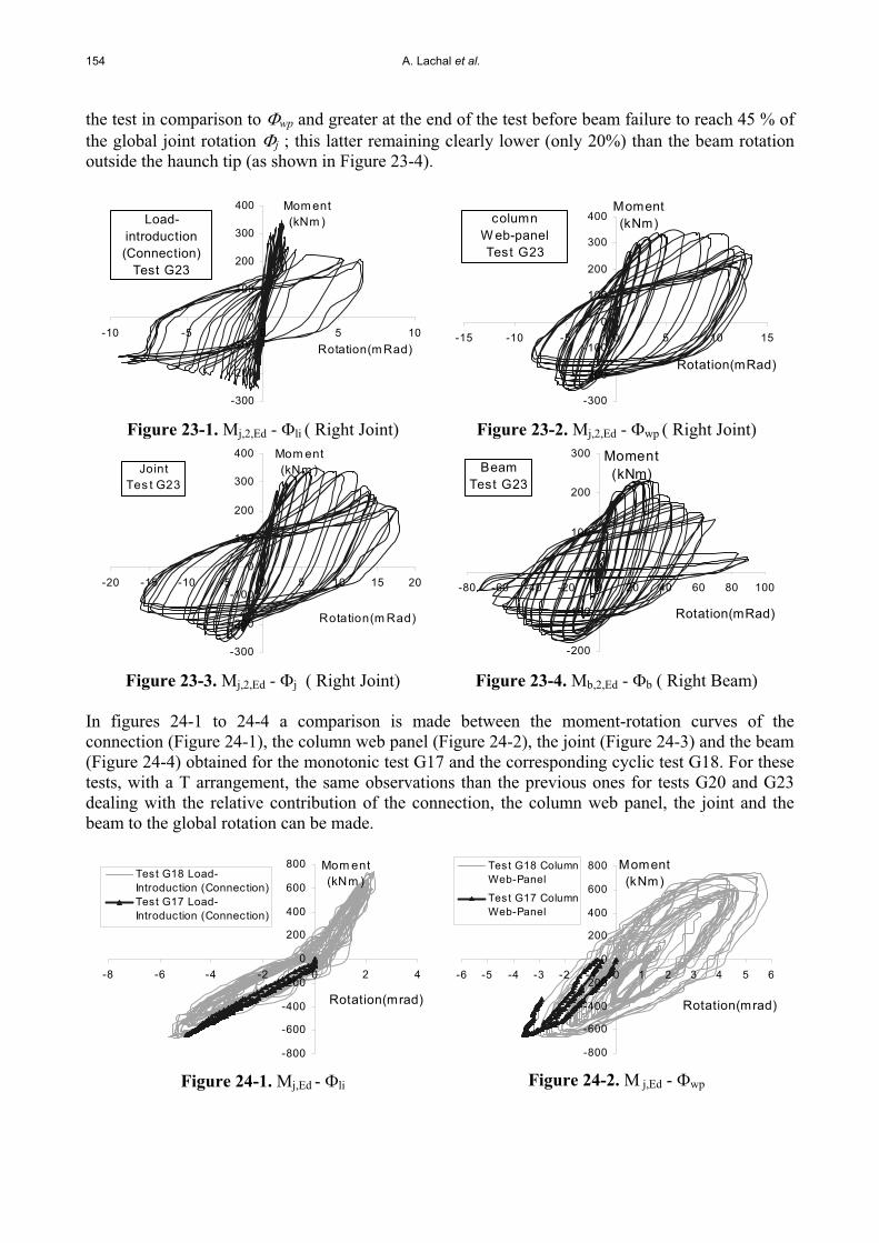
154 A. Lachal et al.
the test in comparison to wp and greater at the end of the test before beam failure to reach 45 % of the global joint rotation j ; this latter remaining clearly lower (only 20%) than the beam rotation outside the haunch tip (as shown in Figure 23-4).
-300
-200
-100
0
100
200
300
400
-10 -5 0 5 10Rotation(m Rad)
Mom ent(kNm )Load-
introduction (Connection)
Test G23
Figure 23-1. Mj,2,Ed - li ( Right Joint)
-300
-200
-100
0
100
200
300
400
-15 -10 -5 0 5 10 15
Rotation(mRad)
Moment(kNm)column
W eb-panel Test G23
Figure 23-2. Mj,2,Ed - wp ( Right Joint)
-300
-200
-100
0
100
200
300
400
-20 -15 -10 -5 0 5 10 15 20
Rotation(m Rad)
Mom ent(kNm )Joint
Tes t G23
Figure 23-3. Mj,2,Ed - j ( Right Joint)
-200
-100
0
100
200
300
-80 -60 -40 -20 0 20 40 60 80 100
Rotation(mRad)
Moment(kNm)Beam
Test G23
Figure 23-4. Mb,2,Ed - b ( Right Beam)
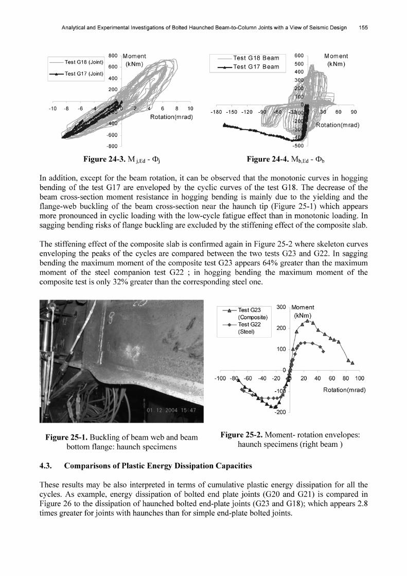
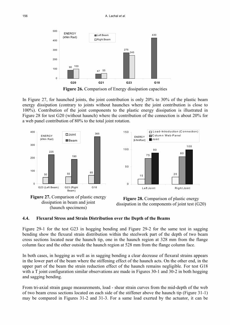
In figures 24-1 to 24-4 a comparison is made between the moment-rotation curves of the connection (Figure 24-1), the column web panel (Figure 24-2), the joint (Figure 24-3) and the beam (Figure 24-4) obtained for the monotonic test G17 and the corresponding cyclic test G18. For these tests, with a T arrangement, the same observations than the previous ones for tests G20 and G23 dealing with the relative contribution of the connection, the column web panel, the joint and the beam to the global rotation can be made.
-800
-600
-400
-200
0
200
400
600
800
-8 -6 -4 -2 0 2 4
Rotation(mrad)
Mom ent(kNm )Test G18 Load-
Introduction (Connection)Test G17 Load-Introduction (Connection)
Figure 24-1. Mj,Ed - li
-800
-600
-400
-200
0
200
400
600
800
-6 -5 -4 -3 -2 -1 0 1 2 3 4 5 6
Rotation(mrad)
Moment(kNm)
Test G18 ColumnWeb-Panel
Test G17 ColumnWeb-Panel
Figure 24-2. M j,Ed - wp
156 A. Lachal et al.
9047
275
430
100
55
245
0
100
200
300
400
500
G20 G21 G23 G18
ENERGY (kNm Rad)
Left Beam
Right Beam
Figure 26. Comparison of Energy dissipation capacities
In Figure 27, for haunched joints, the joint contribution is only 20% to 30% of the plastic beam energy dissipation (contrary to joints without haunches where the joint contribution is close to 100%). Contribution of the joint components to the plastic energy dissipation is illustrated in Figure 28 for test G20 (without haunch) where the contribution of the connection is about 20% for a web panel contribution of 80% to the total joint rotation.
50 55 65
225
190
365
0
100
200
300
400
G23 (Left Beam) G23 (RightBeam)
G18
ENERGY (kNm Rad)
Joint
Beam
Figure 27. Comparison of plastic energy dissipation in beam and joint
(haunch specimens)
1 5 2 0
7 58 0
9 01 0 0
0
5 0
1 0 0
1 5 0
L e ft Jo in t Rig h t Jo in t
ENERG Y [k NmRad]
L o a d - In tro d u ctio n (C o n n e cti o n )C olu m n We b -P a n e lJo in t
Figure 28. Comparison of plastic energy dissipation in the components of joint test (G20)
4.4. Flexural Stress and Strain Distribution over the Depth of the Beams
Figure 29-1 for the test G23 in hogging bending and Figure 29-2 for the same test in sagging bending show the flexural strain distribution within the steelwork part of the depth of two beam cross sections located near the haunch tip, one in the haunch region at 328 mm from the flange column face and the other outside the haunch region at 528 mm from the flange column face.
In both cases, in hogging as well as in sagging bending a clear decrease of flexural strains appears in the lower part of the beam where the stiffening effect of the haunch acts. On the other end, in the upper part of the beam the strain reduction effect of the haunch remains negligible. For test G18 with a T joint configuration similar observations are made in Figures 30-1 and 30-2 in both hogging and sagging bending.
From tri-axial strain gauge measurements, load - shear strain curves from the mid-depth of the web of two beam cross sections located on each side of the stiffener above the haunch tip (Figure 31-1) may be compared in Figures 31-2 and 31-3. For a same load exerted by the actuator, it can be
Analytical and Experimental Investigations of Bolted Haunched Beam-to-Column Joints with a View of Seismic Design 157
observed that the shear strain in the haunch region is in opposite direction as compared with the corresponding shear strain outside the haunch region, the range of shear strain variation being more reduced in the haunch region than outside the haunch region.
This experimental result is a direct consequence of the effect of the vertical shear reaction transmitted by the haunch flange to the beam at the haunch tip. It confirms the hypotheses adopted previously in the haunch static design.
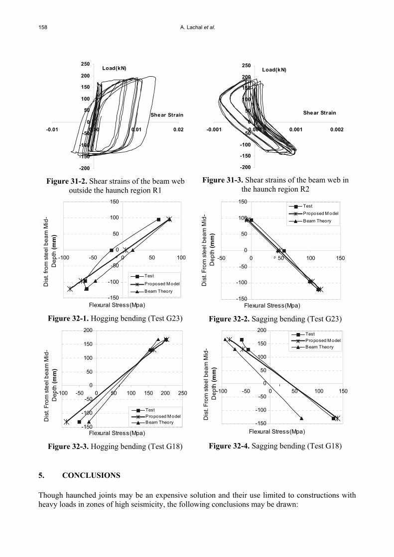
Flexural stress distributions within the depth of the steel beam in the haunch region at 328 mm from the flange column face are presented in Figures 32-1, 32-2, 32-3 and 32-4 for both tests G23 (cruciform internal joint) and G18 (T external joint). Test results are compared with two theoretical ones issued from the above proposed haunch design model on the one hand and from the simple beam theory on the other hand assuming the haunch region as a length of beam of variable cross-section. A better accordance appears between experimental results and the proposed model than the beam theory one, more particularly for test G18 where the depth beam (IPE360) is higher than for test G23 (IPE 240).
-150
-100
-50
0
50
100
150
-1000 -800 -600 -400 -200 0 200 400 600 800 1000
Flexural Strain(x10e-6)
Dis
t. fro
m s
teel
bea
m M
id-
Dep
th (m
m)
beam outside thehaunch regionbeam in thehaunch region
Figure 29-1. Hogging bending (Test G23)
-150
-100
-50
0
50
100
150
-1000 -800 -600 -400 -200 0 200 400 600 800 1000
Flexural Strain (x10e-6)
Dis
t. fro
m s
teel
bea
m M
id-
Dep
th (m
m)
beam outside thehaunch regionbeam in thehaunch region
Figure 29-2. Sagging bending (Test G23)
-150
-100
-50
0
50
100
150
200
-1500 -1000 -500 0 500 1000 1500 2000 2500
Flexural Strain (x10e-6)
Dis
t. fro
m s
teel
bea
m M
id-
Dep
th (m
m)
beam outside thehaunch regionbeam in thehaunch region
Figure 30-1. Hogging bending (Test G18)
-150
-100
-50
0
50
100
150
200
-1500 -1000 -500 0 500 1000 1500 2000 2500
Flexural Strain (x10e-6)
Dis
t. fro
m s
teel
bea
m M
id-
Dep
th (m
m)
beam outside thehaunch regionbeam in thehaunch region
Figure 30-2. Sagging bending (Test G18)
200Right BeamLeft Beam
R1R2
Figure 31-1. Location of rosette strain gauges
158 A. Lachal et al.
-200
-150
-100
-50
0
50
100
150
200
250
-0.01 0.00 0.01 0.02
Shear Strain
Load(kN)
Figure 31-2. Shear strains of the beam web outside the haunch region R1
-200
-150
-100
-50
0
50
100
150
200
250
-0.001 0.000 0.001 0.002
Shear Strain
Load(kN)
Figure 31-3. Shear strains of the beam web in the haunch region R2
-150
-100
-50
0
50
100
150
-100 -50 0 50 100
Flexural Stress(Mpa)
Dis
t. fro
m s
teel
bea
m M
id-
Dep
th (m
m)
Test
Proposed M odelBeam Theory
p
Figure 32-1. Hogging bending (Test G23)
-150
-100
-50
0
50
100
150
-50 0 50 100 150
Flexural Stress(Mpa)
Dis
t. Fr
om s
teel
bea
m M
id-
Dep
th (m
m)
TestProposed M odel
Beam Theory
p
Figure 32-2. Sagging bending (Test G23)
-150
-100
-50
0
50
100
150
200
-100 -50 0 50 100 150 200 250
Flexural Stress(Mpa)
Dis
t. Fr
om s
teel
bea
m M
id-
Dep
th (m
m)
TestProposed M odelBeam Theory
p
Figure 32-3. Hogging bending (Test G18)
-150
-100
-50
0
50
100
150
200
-100 -50 0 50 100 150
Flexural Stress(Mpa)
Dis
t. Fr
om s
teel
bea
m M
id-
Dep
th (m
m)
TestProposed M odelBeam Theory
p
Figure 32-4. Sagging bending (Test G18)
5. CONCLUSIONS
Though haunched joints may be an expensive solution and their use limited to constructions with heavy loads in zones of high seismicity, the following conclusions may be drawn:

Analytical and Experimental Investigations of Bolted Haunched Beam-to-Column Joints with a View of Seismic Design 159
Above results confirm, as well as for joints with a T arrangement than joints with a cruciform arrangement, that the use of haunch with a triangular shape cut out directly from a steel beam appears as a good solution to strengthen beam-to-column joints.
Haunch solution improved significantly joint cyclic performances. Plastic energy dissipation may be twice greater at least and the rotation capacity can exceed 35mrad without risk of low-cycle fatigue rupture in the welds connecting beam flanges on the end-plates. A significant increase of rotational stiffness, moment resistance and rotation capacity was observed in comparison with similar beam-to-column composite joints without haunches.
The stiffening effect of the composite slab prevents any risk of buckling in the upper beam flange leading under sagging cyclic bending to an increase of 60% of the maximum moment compared with a same steel joint. On the other hand, in hogging bending, the composite slab does not bring reinforcing effect on the lower beam flange and the increase of the maximal moment is only 30%.
Experimental results are rather in good agreement with the simplified model developed by the authors which appears well adapted for the haunch static design in composite beam-to-column joints.
It has been shown that Eurocodes 3 and 4 which do not give specific provisions about haunch strengthening, may offer a basic design guidance to suitably predict initial stiffnesses and moment resistances.
ACKNOWLEDGEMENTS
The authors would like to thank the “French Ministry for Infrastructure, Transport, Spatial planning, Tourisme and the sea” through the DRAST (Research management) managed by Prof. André Colson for the financial support to the experimental part of this research.
REFERENCES
[1] Eurocode 3: Design of Steel Structures Part 1-1: General rules for buildings, European Committee for Standardization, CEN, 2003.
[2] Eurocode 3: Design of Steel Structures Part 1-3: General rules – supplementary rules for cold-formed thin gauge members and sheeting, European Committee for Standardization, CEN, 2003.
[3] Eurocode 3: Design of Steel Structures Part 1-8: Design of joints, European Committee for Standardization, CEN, 2003.
[4] Eurocode 4: Design of composite steel and concrete structures Part 1-1: General rules and rules for buildings, European Committee for Standardization, CEN, 2003.
[5] Eurocode 8: Design of structures for earthquake resistance Part 1: General rules, seismic actions and rules for buildings, European Committee for Standardization, CEN, 2003.
[6] Eurocode 8: Design of structures for earthquake resistance Part 3: Strengthening and repair of buildings, European Committee for Standardization, CEN, 2003.
[7] Rep. No. SAC-96-01, SAC Joint Venture, Sacramento, Calif., 1996. [8] Lee, C.H. and Uang, C.-M., “Analytical modeling of dual panel zone in haunch repaired
SAC, ‘‘Technical report: Experimental investigations of beam-column subassemblies.’’ steel MRFs”, Journal of Structural Engineering, ASCE, 1997, 123(1), pp.20-29.
160 A. Lachal et al.
[9] NIST, Modification of existing Welded Steel Moment Frame Connections for Seismic Resistance, Draft Report, National Institute for Standards and Testing, Gaithersburg, MD,1998.
[10] Gross, J.L., Engelhardt, M.D., Uang, C.M., Kasai, K. and Iwankiw, N.R., “Modification of Existing Welded Steel Moment Frame Connections for Seismic Resistance”, AISC Design Guide Series 12, American Institute of Steel Construction, Chicago, Illinois, 1999.
[11] Yu, Q.-S., Uang, C.-M. and Gross, J., “Seismic rehabilitation design of steel moment connection with welded haunch”, Journal of Structural Engineering, ASCE, 2000, 126(1), pp.69-78.
[12] FEMA- 355D, “State of the Art Report on Connection Performance”. Ch 3, 2000. [13] FEMA- 351, “Recommended Seismic Evaluation and Upgrade Criteria for Exixting Welded
Moment-Frame Buildings”, Ch 6, 2000. [14] Ciutina, A., Aribert, J.M. and Lachal, A., “Testing and numerical modelling of steel and
composite bolted joints under seismic cyclic loads”, French Journal of Steel Construction, 2004, n 1, pp.3-33.
[15] ECCS, “Recommended Testing Procedures for Assessing the Behaviour of Structural Elements under Cyclic Loads”, TC 1, TWG 1.3 – Seismic Design, 1986, n 45.