Embed Size (px)
Citation preview

PolyGard is a registered trademark of MSR GAMGC02E01 Phone: 0049(0)8531/9004-0 Fax: 0049(0)8531/9004-54 Specification subject to change without notice. MSR-Electronic GmbH, Würdinger Str. 27, D 94060 Pocking www.msr-electronic.de Printed in Germany
PolyGard® Gas Controller MGC-02 Analog Gas Controller Serial Number - 15 User Manual June 2005

User Manual PolyGard® MGC-02
Page 2
PolyGard is a registered trademark of MSR GAMGC02E01 Phone: 0049(0)8531/9004-0 Fax: 0049(0)8531/9004-54 Specification subject to change without notice. MSR-Electronic GmbH, Würdinger Str. 27, D 94060 Pocking www.msr-electronic.de Printed in Germany
1 Description................................................................................................................................................ 4 2 Operating Instruction............................................................................................................................... 5
2.1 Describtion Keypad User Interface ..................................................................................................... 5 2.2 Setting / Change Parameter or Set points .......................................................................................... 5 2.3 Code Level .......................................................................................................................................... 6
3 Menu Overview ......................................................................................................................................... 7 3.1 Malfunction management.................................................................................................................... 8
3.1.1 Acknowledge a malfunction ......................................................................................................... 8 3.1.2 Error Memory ............................................................................................................................... 8 3.1.3 System Errors .............................................................................................................................. 9
3.2 Status Alarm...................................................................................................................................... 10 3.3 Status Relay...................................................................................................................................... 10
3.3.1 Manual operation of the relay .................................................................................................... 10 3.4 Menu Measuring Values ................................................................................................................... 11 3.5 Menu Relay Parameter ..................................................................................................................... 11
3.5.1 Relay Mode................................................................................................................................ 12 3.5.2 Relay Function Static / Flash ..................................................................................................... 12 3.5.3 Latching Mode ........................................................................................................................... 12 3.5.4 Horn Function ............................................................................................................................ 13 3.5.5 External Relay operation............................................................................................................ 14
3.6 Menu MP Parameter ......................................................................................................................... 14 3.6.1 Activate – Deactivate MP........................................................................................................... 15 3.6.2 Selection Gastype...................................................................................................................... 15 3.6.3 Measuring range ........................................................................................................................ 16 3.6.4 MP Signal................................................................................................................................... 16 3.6.5 Threshold / Hysteresis ............................................................................................................... 16 3.6.6 Delay Alarm ON or OFF............................................................................................................. 16 3.6.7 Control Mode ............................................................................................................................. 17 3.6.8 Assigned MP Fault to Alarm ...................................................................................................... 17 3.6.9 Assigned Alarm to Alarm relay .................................................................................................. 17 3.6.10 Assigned MP Signal to analog Output ....................................................................................... 17
3.7 Menu System Parameter .................................................................................................................. 18 3.7.1 Service Mode ............................................................................................................................. 19 3.7.2 Software Version........................................................................................................................ 19 3.7.3 Maintenance Concept ................................................................................................................ 20 3.7.4 Average Function....................................................................................................................... 20 3.7.5 Systemtime, Systemdate ........................................................................................................... 20 3.7.6 Customer Password (Code 1).................................................................................................... 20 3.7.7 Analog Output ............................................................................................................................ 21 3.7.8 Define the Failure Relay ............................................................................................................ 21 3.7.9 Power On Time .......................................................................................................................... 21 3.7.10 Registration of expansions modules.......................................................................................... 21

User Manual PolyGard® MGC-02
Page 3
PolyGard is a registered trademark of MSR GAMGC02E01 Phone: 0049(0)8531/9004-0 Fax: 0049(0)8531/9004-54 Specification subject to change without notice. MSR-Electronic GmbH, Würdinger Str. 27, D 94060 Pocking www.msr-electronic.de Printed in Germany
4 Mounting / Electrical Connection ......................................................................................................... 22
4.1 Electrical Connection ........................................................................................................................ 22 4.2 Connection Diagram – Power suppy ................................................................................................ 23 4.3 Connection Diagram – Gas Controller Module GC 02...................................................................... 24 4.4 Connection Diagram – EP-02 Module No. 1..................................................................................... 25 4.5 Connection Diagram – EP-02 Module No. 2..................................................................................... 26 4.6 Connection Diagram – EP-02 Module No. 3..................................................................................... 27 4.7 Connection Diagram – EP-02 Module No. 4..................................................................................... 28 4.8 Connection Diagram – EP-02 Module No. 5..................................................................................... 29
5 Start-up Operation.................................................................................................................................. 30 5.1 Start-up.............................................................................................................................................. 30 5.2 Checklist Start-up operation.............................................................................................................. 31
6 Configuration- and Parameter card. ..................................................................................................... 32 6.1 Configurationscard Systemparameter .............................................................................................. 32 6.2 Configurationscard Alarmrelay.......................................................................................................... 32 6.3 Configurationscard Measuring Parameter ........................................................................................ 33
7 Specifications ......................................................................................................................................... 34 8 Appendix module overview................................................................................................................... 35 9 Notes and General Information............................................................................................................. 36
9.1 Intended product application............................................................................................................. 36 9.2 Installers` responsibilities .................................................................................................................. 36 9.3 Maintenance...................................................................................................................................... 36 9.4 Limited warranty................................................................................................................................ 36

User Manual PolyGard® MGC-02
Page 4
PolyGard is a registered trademark of MSR GAMGC02E01 Phone: 0049(0)8531/9004-0 Fax: 0049(0)8531/9004-54 Specification subject to change without notice. MSR-Electronic GmbH, Würdinger Str. 27, D 94060 Pocking www.msr-electronic.de Printed in Germany
Analog Gas Controller System MGC-02
1 Description The PolyGard® MGC-02 Gas Controller is used for the monitoring and warning of toxic- combustible- and refrigerant- gases as well as temperature and humidity. The Gas Controller series MGC-02 can control up to 24 analog (Gas) Transmitters with 4 to 20 mA signal. For each Measuring Point (MP) are adjustable five freely alarm thresholds. Every alarm threshold can be asigned to one of the maximum 20 alarmrelays (R) with changeover, potential free contact. The Gas Controller can interface via 4 to 20 mA outputs to any compatible electronic analog control, DDC/PLC control or automation system.
The free adjustable parameters and alarm threshold make a very flexible use in the gas measuring possible. Simple and comfortable start-up is possibily with the factory adjusted parameters.
The configuration parameter settings and operation is easy to do without program knowledge.
The PolyGard® Gas Controller MGC-02 must not be used in areas showing explosive hazards.

User Manual PolyGard® MGC-02
Page 5
PolyGard is a registered trademark of MSR GAMGC02E01 Phone: 0049(0)8531/9004-0 Fax: 0049(0)8531/9004-54 Specification subject to change without notice. MSR-Electronic GmbH, Würdinger Str. 27, D 94060 Pocking www.msr-electronic.de Printed in Germany
2 Operating Instruction The complete configuration, parameterization and service is made via keypad user interface in combination with the display screen. Security is provided via two password levels.
2.1 Describtion Keypad User Interface
Exits programming and saves settings, returns to the previous menu level. Enter sub menus, stores security password.
Scrolls down & up in Main menu and Sub menus, increases or decreases a value. Moves of cursor. LED yellow Flashes when set one or more Alarm.
LED red: Flashes at System- or Sensor Failure or Maintenance needed.
2.2 Setting / Change Parameter or Set points Desired menu window open. Code window opens, if no code level approved.
After input valid code the cursor jumps on the first position segment which can be changed. Push the cursor onto the position segment, which is to be changed. Change the Parameter /Set Point. Saving the changed value.
Finish
Fault Alarm
MSR - Electronic22.01.05 20:28

User Manual PolyGard® MGC-02
Page 6
PolyGard is a registered trademark of MSR GAMGC02E01 Phone: 0049(0)8531/9004-0 Fax: 0049(0)8531/9004-54 Specification subject to change without notice. MSR-Electronic GmbH, Würdinger Str. 27, D 94060 Pocking www.msr-electronic.de Printed in Germany
2.3 Code Level
All changes of parameters and set point values are protected by four digit numeric Code (= password).
The code level 1 permits the operation of the MGC- 02. This code level is intended for the customer. The code can be individually changed over the code level 2.
With the code level 2 all parameters and set points are released, this code level are reserved for the service technician.
A third code level permits additionally an activate or deactivate of measuring points (MP) and expansions modules (EP).
The release of the code level is deleted if 15 minutes not press a push button.
All menu windows can without release code level be regarded.

User Manual PolyGard® MGC-02
Page 7
PolyGard is a registered trademark of MSR GAMGC02E01 Phone: 0049(0)8531/9004-0 Fax: 0049(0)8531/9004-54 Specification subject to change without notice. MSR-Electronic GmbH, Würdinger Str. 27, D 94060 Pocking www.msr-electronic.de Printed in Germany
3 Menu Overview The operation of the Gas Controller MGC-02 is made by a easy to learn, simply and logical menu structure. The operating menu contains the following levels:
• Starting menu with Date and Time. • Main Menu • Sub Menu 1 and 2
Starting Menu Main Menu Sub Menu
Display and Reset Erros
See from point 3.1
Display the status of actual alarms See at point 3.2
Display the status of relay Manual operation of relay Reset Function of relay See from point 3.3
Display the measuring values See at point 3.4
Display and Change the relay parameter See from point 3.5
Display and Change the Measuring point parameter Activate or Deactivate MP Assigned the alarms to the Alarmrelay See from point 3.6 Display and Change the system parameter See from point 3.7
MSR-Gas-Control 10.02.05 10:38
System Errors
Status Alarm
Status Relay
Measuring Values
Relay Parameter
MP Parameter
System Parameter

User Manual PolyGard® MGC-02
Page 8
PolyGard is a registered trademark of MSR GAMGC02E01 Phone: 0049(0)8531/9004-0 Fax: 0049(0)8531/9004-54 Specification subject to change without notice. MSR-Electronic GmbH, Würdinger Str. 27, D 94060 Pocking www.msr-electronic.de Printed in Germany
MP 01 < 3mA Ereased
Error still exists
3.1 Malfunction management The integrated malfunction management record the last 15 malfunctions with date and time stamps in the menu „System Errors“. Additionally a record of the malfunction occurs in the “Error memory”, which can be selected and cleared only by the service technician.
A malfunction is overlayed as text message in the starting menu. The failure relay which is defined in the system parameter „Failure relay“ is activating. The red LED in the front of the gas controller flashed.
During the malfunction of a measuring point (MP) additionally the alarms are activated, which are defined in the menu „MP Parameter“.
3.1.1 Acknowledge a malfunction Attention: Acknowledging of a malfunction is only possible after the removal of the cause. Select Menu “System Errors” Example: Failure MP 01 < 3 mA Malfunction Reset? Malfunction Reset or
Malfunction Ereased Cause not eliminate Acknowledgement not possible
3.1.2 Error Memory The menu „Error memory“ in the main menu „System Error„ is to be opened only by the code level 2
In the error memory the last 20 malfunction message are listed for the service technician. Even if they in the menu „System Error“ were already acknowledged. The deletion of each individual message occurs similar to the acknowledgement of a malfunction.
System Errors
MP 01 < 3mA 05.02 10.38
MP 01 < 3mA Reset ??
User Manual PolyGard® MGC-02
Page 9
PolyGard is a registered trademark of MSR GAMGC02E01 Phone: 0049(0)8531/9004-0 Fax: 0049(0)8531/9004-54 Specification subject to change without notice. MSR-Electronic GmbH, Würdinger Str. 27, D 94060 Pocking www.msr-electronic.de Printed in Germany
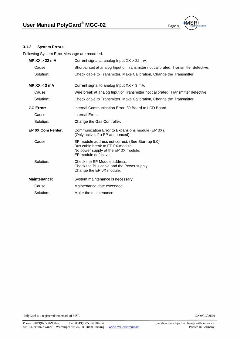
3.1.3 System Errors
Following System Error Message are recorded.
MP XX > 22 mA Current signal at analog Input XX > 22 mA.
Cause: Short-circuit at analog Input or Transmitter not calibrated, Transmitter defective.
Solution: Check cable to Transmitter, Make Calibration, Change the Transmitter.
MP XX < 3 mA Current signal to analog Input XX < 3 mA.
Cause: Wire break at analog Input or Transmitter not calibrated, Transmitter defective.
Solution: Check cable to Transmitter, Make Calibration, Change the Transmitter.
GC Error: Internal Communication Error I/O Board to LCD Board.
Cause: Internal Error.
Solution: Change the Gas Controller.
EP 0X Com Fehler: Communication Error to Expansions module (EP 0X). (Only active, if a EP announced).
Cause: EP module address not correct. (See Start-up 5.0) Bus cable break to EP 0X module. No power supply at the EP 0X module. EP module defective.
Solution: Check the EP Module address. Check the Bus cable and the Power supply.
Change the EP 0X module.
Maintenance: System maintenance is necessary.
Cause: Maintenance date exceeded.
Solution: Make the maintenance.

User Manual PolyGard® MGC-02
Page 10
PolyGard is a registered trademark of MSR GAMGC02E01 Phone: 0049(0)8531/9004-0 Fax: 0049(0)8531/9004-54 Specification subject to change without notice. MSR-Electronic GmbH, Würdinger Str. 27, D 94060 Pocking www.msr-electronic.de Printed in Germany
MP 02 A1 A2
R 01 OFF
3.2 Status Alarm Display the actual alarms in sequence of accumulating. Only the measuring points are overlayed, where an alarm is set. Changes are not possible in this menu.
Symbol Describtion Function
MP 02 Measuring (MP) Point No.
AX Status Alarm
A1 = Alarm 1 ON A2 = Alarm 2 ON A3 = Alarm 3 ON A4 = Alarm 4 ON A5 = Alarm 5 ON
3.3 Status Relay Display the actual status of the Alarm relay. Manual operation of the alarm relays.
Symbol Describtion Setting Status Function
R 01 Relay No. 01 Select Relay No.
OFF Status Relay OFF
OFF ON Manual OFF Manual ON
= Relay Off (No gas alarm) = Relay On (Gas alarm) = Relay manual Off = Relay manual On
3.3.1 Manual operation of the relay
The manual operation of the alarm relays occurs in the menu „Status Relay”. If a relay is in the manual ON or OFF status, shines the yellow alarm LED at the Gas Controller continuously.
The external operation of the alarm relay over an assigned digital input has the priority before the manual operation in the menu "Status Relay" and Gas alarm.
In the menu „Status Relay “manually operated relays are again deleted by selection of the function "Automatic".
Acknowledging the relays by Latching mode occurs also in this menu. Select Relay
Select Function Manual operation
Manual ON = Relay ON Select Function Manual OFF = Relay OFF Automatic = Manual operation delete Reset ? = Acknowledging Latching mode
Take over Function
R 01 OFF
Manual ON
Manual OFF
Manual OFF

User Manual PolyGard® MGC-02
Page 11
PolyGard is a registered trademark of MSR GAMGC02E01 Phone: 0049(0)8531/9004-0 Fax: 0049(0)8531/9004-54 Specification subject to change without notice. MSR-Electronic GmbH, Würdinger Str. 27, D 94060 Pocking www.msr-electronic.de Printed in Germany
MP 01 CO ppm 50 *AV 33 CV
3.4 Menu Measuring Values In this menu occurs the Display of the current value (CV) and average value (AV) with gas unit and gas type for each active measuring point (MP) as well as the defined mode of control (CV or AV mode).
Symbol Describtion Setting Status Function
MP 01 Measuring Point No. Select MP No
CO Gas type CO See 3.6.2 ppm Gas unit See 3.6.2 CV Current value CV Current value of Gas Concentration AV Average value Avergae value (10 measured values within the time unit) * Control mode Display, with Control mode is select. (CV or AV) Not active Status MP Not active MP not announced Error Malfunction MP Current signal < 3 mA or > 22 mA
3.5 Menu Relay Parameter Display and change the parameter for each alarm relay. (Main menu)
(Selection Relay No.)
Relay Mode See 3.5.1
Relay Function See 3.5.2
Activate Latching Mode See 3.5.3
Definition Horn Function See 3.5.4
Definition external Relay Operation
See 3.5.5
Relay Mode De- energized
Static / Flash 0 s
Relay Parameter
R 01
Latching mode No
Time Quitt. DI 0s 0 0
External mode DI: ON = 0: OFF = 0

User Manual PolyGard® MGC-02
Page 12
PolyGard is a registered trademark of MSR GAMGC02E01 Phone: 0049(0)8531/9004-0 Fax: 0049(0)8531/9004-54 Specification subject to change without notice. MSR-Electronic GmbH, Würdinger Str. 27, D 94060 Pocking www.msr-electronic.de Printed in Germany
3.5.1 Relay Mode
Definition Relay Mode:
Symbol Describtion Setting Status Function
R 01 Relay No. Selection Relay De-energized Relay Mode De-
energizedDe-energized Energized
= Alarm ON = Relay ON = Alarm ON = Relay OFF
3.5.2 Relay Function Static / Flash
Definition Relay Function
Symbol Describtion Setting Status Function
R 01 Relay No. Selection Relay
0 Function 0 0 = Relay Function static > 0 = Relay Function flashing ( = Periods time sec.) Impulse / Break = 1:1
3.5.3 Latching Mode
Definition Latching Function
Symbol Describtion Setting Status Function
R 01 Relay No. Selection Relay
No Latching Mode No No Yes
= Latching Mode non active = Latching Mode active
Acknowledging of a latching relay in the menu „Status Relay“ is possible only if the gas concentration is again smaller than the alarm threshold including hysteresis. In this condition the status Latching is overlay.
Example: Alarm relay R2 with Latching mode
Alarm 2
Display in the MenuStatus Relay
Relay 2
Reset in the Menu Status Relay
On
Off
On
Off
On
Off
R2Off
R2On
R2On
R2On
R2Latching
R2Off
Gas Concentration greater smaller as Threshold

User Manual PolyGard® MGC-02
Page 13
PolyGard is a registered trademark of MSR GAMGC02E01 Phone: 0049(0)8531/9004-0 Fax: 0049(0)8531/9004-54 Specification subject to change without notice. MSR-Electronic GmbH, Würdinger Str. 27, D 94060 Pocking www.msr-electronic.de Printed in Germany
3.5.4 Horn Function
With this parameter the alarm relay is defined as horn relay with the following acknowledging possibilities.
• By press of one the arbitrary 6 pushbutton. (Only possible in the starting menu). • Automatic acknowledging at time run off. • By an external pushbutton. (Assignment appropriate digital input).
The horn function is activated only if at least one of the two parameters (time or digital input) is set.
Special function Response
After acknowledging the relay (over Pushbutton or externally) time starts. If this time run off and if the alarm still acting, the relay is again set.
Symbol Describtion Setting Status Function
R 04 Relay No. Selection Relay
Quitt Mode 0 0 = Acknowledge the relay at time run off, or over Pushbutton 1 = Acknowledge the relay over Pushbutton, af time run off and alarm is still acting, relay is set again. (Response function).
Time 120 Time for function Automatic acknowledging or Response function 0 = non acknowledging function
DI 0 Assignment, which digital input acknowledges the relay.
Acknowledge the horn relay
Alarm 4
Relay 4
Gas Concentration greater smaller as Threshold
Acknowledgingsignal
On
Of
On
Off
On
Off
Time
Special function „Response“. (Return of the horn relay)
Alarm 4
Relay 4
Gas Concentration greater smaller as Threshold
Acknowledging-signal
On
Off
On
Off
On
Off
Time Time

User Manual PolyGard® MGC-02
Page 14
PolyGard is a registered trademark of MSR GAMGC02E01 Phone: 0049(0)8531/9004-0 Fax: 0049(0)8531/9004-54 Specification subject to change without notice. MSR-Electronic GmbH, Würdinger Str. 27, D 94060 Pocking www.msr-electronic.de Printed in Germany
3.5.5 External Relay operation.
Assigned one digital input (DI) for external set the alarm relay ON and/or OFF. This function has priority before a gas alarm and/or manual switching in the menu „Status Relay“.
Symbol Describtion Setting Status Function
R 01 Relay No. Selection Relay DI-ON External On 0 If digital input closed, relay switch ON DI-OFF External Off 0 If digital input closed, relay switch OFF
3.6 Menu MP Parameter Display and Change Parameters, Assigned Alarms to Alarmrelay and activate each Measuring Point (MP). (Main Menu)
(Selection MP)
Activate or deactivate MP See 3.6.1
Define Gastype See 3.6.2
Define Meassuring range See 3.6.3
Adjustment signal form of transmitter See 3.6.4
Define Threshold 1 See 3.6.5
Define Threshold 2 See 3.6.5
Define Threshold 3 See 3.6.5
Define Threshold 4 See 3.6.5
MP Mode active
Gastype CO
MP Parameter
MP 01 active
Measuring range 300 ppm
MP-Signal linear
Threshold 1 40 ppm
Threshold 2 80 ppm
Threshold 3 100 ppm
Threshold 4 120 ppm

User Manual PolyGard® MGC-02
Page 15
PolyGard is a registered trademark of MSR GAMGC02E01 Phone: 0049(0)8531/9004-0 Fax: 0049(0)8531/9004-54 Specification subject to change without notice. MSR-Electronic GmbH, Würdinger Str. 27, D 94060 Pocking www.msr-electronic.de Printed in Germany
Define Threshold 5 See 3.6.5
Hysteresis See 3.6.5
Set Delay ON time See 3.6.6
Set Delay OFF time See 3.6.6
Define Control Mode See 3.6.7
Assigned MP Fault to Alarm See 3.6.8
Assigned Alarm to Alarmrelay Assigned MP to analog output See 3.6.9 and 3.6.10 3.6.1 Activate – Deactivate MP
Symbol Describtion Setting Status Function
MP 01 Measuring point Selection MP No.
Active MP Status not active
active = Measuring point announced not active = Measuring point not announced
3.6.2 Selection Gastype
Assign Gastype to attached gas transmitters.
Symbol Describtion Setting Status Gastype Unit Measuring
range1 MP 01 Measuring point .
CO Gastype CO
CO Ex NO NO2 NH3 O2 CO2 R11 R123 R134 R22 Temp RH
Carbon monoxide Combusible Gase Nitric monoxide Nitric dioxide Ammonia Oxygen2
Carbon dioxide Refrigerant gase Refrigerant gase Refrigerant gase Refrigerant gase Temperature Humidity
ppm %LEL ppm ppm ppm %V/V ppm ppm ppm ppm ppm °C % RH
0 – 300 0 – 100 0 – 50 0 – 25 0 – 300 0 – 25 0 – 2000 0 –xxx 0 – xx 0 – xx 0 – xx -- 0 – 100
1 Non obligation Recommendation 2 During oxygen measurement falling signal!
Threshold 5 300 ppm
Hysteresis 15 ppm
Delay ON time 0 s
Delay OFF time 0 s
C/A Mode CV
Alarm - 1 2 3 4 5 Fault - 1 1 0 0 0
A1; A2; A3; A4; A5; AO01; 02; 03, 04; 05; 0

User Manual PolyGard® MGC-02
Page 16
PolyGard is a registered trademark of MSR GAMGC02E01 Phone: 0049(0)8531/9004-0 Fax: 0049(0)8531/9004-54 Specification subject to change without notice. MSR-Electronic GmbH, Würdinger Str. 27, D 94060 Pocking www.msr-electronic.de Printed in Germany
3.6.3 Measuring range
The measuring range can be defined within 10 to 10000 freely. The measuring range in the table gastype are non obligation recommendations.
The measuring range must agree with the signal (4 to 20 mA) attached gas transmitters. (4 mA = Display 0 (ppm), 20 mA = Display Measuring range max. point) 3.6.4 MP Signal
Gas transmitter with electro-chemical - or catalytic beat gas sensors spends in rule a linear, for gas concentration proportional 4 to 20 mA signal.
Semiconductors gas sensors spend a not linear (exponential) signal. This signal leads to a non linear 4 to 20 mA signal of the gas transmitter.
The Gas Controller MGC-02 is for both type of gas transmitters prepared. The classification of signals is defined in this menu.
Symbol Describtion Setting Status Function
MP 01 Measuring Point Selection MP No.
Linear MP Signal linear linear = Transmitter with linear Output signal Non linear = Transmitter with non linear Output signal (Only Series AT from MSR-E)
3.6.5 Threshold / Hysteresis
For each measuring point five alarm thresholds for the free definition are available. If the gas concentration greater the adjusted alarm threshold, the associated alarm is set. If the gas concentration falls below the alarm threshold inclusive hysteresis the alarm is again put back.
Not Necessary alarm thresholds to be defined on measuring range end point, in order to avoid false alarms. With O2 measurement ocurs an alarm release with falling measuring signal!
Symbol Describtion Default Status
Function
MP 01 Measuring Point Selection MP No.
40 ppm Threshold
40 80 100 120 300 15
Threshold 1 Threshold 2 Threshold 3 Threshold 4 Threshold 5 Hysteresis
Gasconcentration > Threshold 1 = Alarm 1 Gasconcentration > Threshold 2 = Alarm 2 Gasconcentration > Threshold 3 = Alarm 3 Gasconcentration > Threshold 4 = Alarm 4 Gasconcentration > Threshold 5 = Alarm 5 Gasconcentration < (Threshold X –Hysteresis) = Alarm X OFF
3.6.6 Delay Alarm ON or OFF
Definition Delay Alarm ON and/or Alarm OFF. The function applies to all alarm by this MP.
Symbol Describtion Default Status Function
MP 01 Measuring Point Selection MP No.
0 s Delay Time ON 0 Gasconcentration > Threshold: Alarm is only activated at expiration of the defined time (sec.). 0 sec. = No Delay
0 s Delay Time OFF 0 Gasconcentration < Threshold: Alarm is only deactivated at expiration of the defined time (sec.). 0 sec. = No Delay

User Manual PolyGard® MGC-02
Page 17
PolyGard is a registered trademark of MSR GAMGC02E01 Phone: 0049(0)8531/9004-0 Fax: 0049(0)8531/9004-54 Specification subject to change without notice. MSR-Electronic GmbH, Würdinger Str. 27, D 94060 Pocking www.msr-electronic.de Printed in Germany
3.6.7 Control Mode
Definition of the alarm evaluation by Current (CV) or Average value (AV).
Symbol Describtion Default Status t Function
MP 01 Measuring Point Selection MP No.
CV Evaluation CV CV = Control the Current Gas value AV = Control the Average Gas value
Current- Average Value Function See: 3.7.4
3.6.8 Assigned MP Fault to Alarm Define, which alarms are activated with a failure at the measuring point.
Symbol Describtion Default Status Function
MP 01 Measuring Point Selection MP No. Alarm - 1 2 3 4 5 Fault - 1 1 0 0 0 Failure MP 1 1 0 0 0 0 = Alarm not ON at MP Failure
1 = Alarm ON at MP Failure
3.6.9 Assigned Alarm to Alarm relay
Each of the 5 alarms can be assigned to a freely selectable alarm relay. Alarms, those not to be needed do not receive assignment.
Symbol Describtion Default Status Function
MP 01 Measuring Point Selection MP No.
1
A1 A2 A3 A4 A5
01 02 03 04 00
01 = Alarm 1 activate Alarmrelay R 01 02 = Alarm 2 activate Alarmrelay R 02 03 = Alarm 3 activate Alarmrelay R 03 04 = Alarm 4 activate Alarmrelay R 04 00 = Alarm 5 activate no any Alarmrelay
0 A 0 0 = MP Signal no assigned to any analog output 1 = MP Signal assigned to analog output 1 2 = MP Signal assigned to analog output 2
3.6.10 Assigned MP Signal to analog Output
The measuring point signal can be assigned to one of the two analog Outputs. The signal defined in the control mode (current or average value) is transmitted. The assignment occurs in the menu „assignment alarm < > alarm relay” in the right place.
Analog output see also: 3.7.2

User Manual PolyGard® MGC-02
Page 18
PolyGard is a registered trademark of MSR GAMGC02E01 Phone: 0049(0)8531/9004-0 Fax: 0049(0)8531/9004-54 Specification subject to change without notice. MSR-Electronic GmbH, Würdinger Str. 27, D 94060 Pocking www.msr-electronic.de Printed in Germany
3.7 Menu System Parameter Display and change the System Parameter for the Gas Controller (Main Menu)
See 3.7.1
See 3.7.2
See 3.7.3
See 3.7.3
See 3.7.4
See 3.7.4
See 3.7.5
See 3.7.5
See 3.7.5
See 3.7.6
See 3.7.7
Siehe See 3.7.7
Software Version GC02- XX
Next maint. Date TT.MM.JJ
System Parameter
Service Mode OFF
Service Phone +49/(0)8531/90040
AV Overlay 120 s. 120 ppm
AV Time 1800 s
Time system EU
Date TT.MM.JJ
Customers Pass Change ****
Analog Output 1 Max.
Calibration AO 1 4.0=4 mA 20 = 20.0
Time hh:mm:ss

User Manual PolyGard® MGC-02
Page 19
PolyGard is a registered trademark of MSR GAMGC02E01 Phone: 0049(0)8531/9004-0 Fax: 0049(0)8531/9004-54 Specification subject to change without notice. MSR-Electronic GmbH, Würdinger Str. 27, D 94060 Pocking www.msr-electronic.de Printed in Germany
See 3.7.7
See 3.7.7
See 3.7.8
See 3.7.9
See 3.7.10
See 3.7.10
See 3.7.10
See 3.7.10
See 3.7.10 3.7.1 Service Mode
If the Sevice mode is active (ON) then the alarms are not passed on to the alarm relays. (For Calibrate or Service work). The service mode is Reset automatically after 60 minutes or in the menu “service mode” manually.
Symbol Describtion Default Status Function
Off Service Mode Off Off = Alarms activate the associated alarm relays On = Alarms are not passed on to the alarm relays
3.7.2 Software Version
Symbol Describtion Default Status Function
GC02-XX
Software Version XX = Software Version
Analog Output 2 Max.
Calibration AO 2 4.0=4 mA 20 = 20.0
Failure Relay 05
Power On Time 30 s
EP Module 1 Not active
EP Module 2 Not active
EP Module 3 Not active
EP Module 4 Not active
EP Module 5 Not active

User Manual PolyGard® MGC-02
Page 20
PolyGard is a registered trademark of MSR GAMGC02E01 Phone: 0049(0)8531/9004-0 Fax: 0049(0)8531/9004-54 Specification subject to change without notice. MSR-Electronic GmbH, Würdinger Str. 27, D 94060 Pocking www.msr-electronic.de Printed in Germany
3.7.3 Maintenance Concept
In the MGC-02 system is a monitoring of the maintenance intervals, given by the Regulations or Customer, integrated.
With start-up and/or after maintenance the date for next due maintenance is entered. With reaching this date on the next morning at 9 o'clock the failure signal is activated and in the display the phone No. of the service technician is overlay. The failure signal (maintenance) can be acknowledged by the operator. The maintenance message (Service Phone No.) is put back after accomplished maintenance with input next maintenance date.
The service phone No. can be individually entered in the next menu.
Symbol Describtion Default Status Function
TT.MM.JJ Maintenance date TT.MM.JJ = Input date for next maintenance. 0853.... Phone No. Input the individual service phone No.
3.7.4 Average Function
The Gas Controller calculate for each active measuring point the arithmetic average value from 10 measurements within time unit defined in the menu „AV-time“. This average value is indicated in the menu “Measuring Values” near the current value. At each Measuring Point the control mode of current value or average value for the alarm evaluation is defined.
The alarm evaluation of the control mode average value is overlaid by the current value, if this exceeds alarm threshold defined in the menu „AV-Overlay“.The overlay is delay with the time factor in this menu.
Symbol Describtion Default Status Function
120 s 120 ppm AV- Overlay 120 s
120 ppm sec. = Delay time average value Overlay. 0 = No overlay Function ppm = Threshold average Overlay
1800 s AV-Time 1800 s sec. = Time for calculate average value
3.7.5 Systemtime, Systemdate
Input and correction of the time and date. Selection of the time and date format.
Symbol Describtion Default Status Function
EU Time format EU EU = Display time and date in EU format US = Display time and date in US format
hh.mm.ss Time hh.mm.ss = Input the correct time (EU format) hh.mm.ss am = Input the correct time (US format)
TT.MM.JJ Date TT.MM.JJ = Input the correct date (EU format) MM.TT.JJ = Input the correct date (US format)
3.7.6 Customer Password (Code 1)
Change the Systempassword for level 1
Symbol Describtion Default Status Function
1234 Customer- password 1234 1234 = Define the Customer Password with 4 characters

User Manual PolyGard® MGC-02
Page 21
PolyGard is a registered trademark of MSR GAMGC02E01 Phone: 0049(0)8531/9004-0 Fax: 0049(0)8531/9004-54 Specification subject to change without notice. MSR-Electronic GmbH, Würdinger Str. 27, D 94060 Pocking www.msr-electronic.de Printed in Germany
3.7.7 Analog Output
The Gas Contoller has two analog outputs (AO) with 4 to 20 mA signal. Each of the analog output can be assigned the signal of one or more measuring points. The assignment occurs in the menu „MP Parameter“ for each MP. The measuring point sends the signal, which is defined in the menu „C/A Mode“.
The Gas Controller determined from the signal of all assigned measuring points the minimum, the maximum or the average value and spends in at analog output. The definition, which value is spent effected in the menu „Analog Output X“.
The analog output can be calibrated with 4 and with 20 mA. In addition at the AO an ampere meter (measuring range 25 mA) is attached and the respective factor changed to the analog output 4 and/or 20 mA corresponds. During the calibration ocurrs no evaluation of the measuring point signals. This calibration occurs factory-set. The factors should not be changed.
Symbol Describtion Default Status Function
Max. Select Output mode Max.
Min. = Spends the minimum value of all assigned MP Max. = Spends the maximum value of all assigned MP Average = Spends the average value of all assigned MP
4.0 20.0 Calibration 4.0
20.0 4.0 = Calibration factor at 4 mA 20.0 = Calibration factor at 20 mA
3.7.8 Define the Failure Relay
Define the Failure Relay. See also malfunction managemnet (3.1)
Symbol Describtion Default Status Function
05 SSM Relay R05 R05 = Define failure relay 3.7.9 Power On Time
Gas sensors need a break-in period, until the chemical process of the sensor reaches a stable condition. During this break-in period the current signal can lead to unwanted releasing of a pseudo alarm. Therefore at the Gas Controller is started after switching on of the power supply the Power On Time. While this time runs off, the Gas Controller does not spend alarms. The power on status is overlay in the starting menu.
Symbol Describtion Default Status Function
30 s Power On Time 30 s XX = Define the Power On Time (sec.) 3.7.10 Registration of expansions modules
The gas Controller can manage, up to five expansions modules (EP-02). Each EP-02 has four analog inputs and five alarm relay. Each attached EP-02 is announced in this menu. The Controller monitors the communication to the announced EP-02 modules and spends at a communication error a fault signal. For the recognition of the position of the EP-02 modules a module address is assigned to each module with the address selector. See table.
The table shows the assignment of the MP and relay numbers to the individual modules.
Symbol Describtion Default Status Function Module
Adr. Relay No. MP No.
EP- Module No 1 Not active 1 06 to 10 05 to 08 EP- Module No 2 Not active 2 11 to 15 09 to 12 EP- Module No 3 Not active 3 16 to 20 13 to 16 EP- Module No 4 Not active 4 ---- 17 to 20
Not active
EP- Module No 5 Not active
Active = Module announced. Not active = Module not announced
5 ---- 21 to 24

User Manual PolyGard® MGC-02
Page 22
PolyGard is a registered trademark of MSR GAMGC02E01 Phone: 0049(0)8531/9004-0 Fax: 0049(0)8531/9004-54 Specification subject to change without notice. MSR-Electronic GmbH, Würdinger Str. 27, D 94060 Pocking www.msr-electronic.de Printed in Germany
4 Mounting / Electrical Connection
The Gas Controller is installed at the 4 marked mounting holes at housing back side to the wall. These mounting holes are accessible after opening the housing. See Fig. 01 The dimension XX are depend from MGC-02 type and can be read from the back of housing.
The mounting holes are covered with the enclosed caps after the end of the assembly.
As recommend to consider with the selection of the assembly place:
• Assembly hight approx. 1.6 m for the simple condition. • Cables are introduced both, from above and from downside. • On the left side to keep at least 150 mm distance to open the transparent door. • Defaults of the Customer.
Fig. 01
4.1 Electrical Connection Ah the installation must be considered the technical requirements and regulations for wiring, electrical security, as well as project specific and Environmental conditions etc.. We recommend the following cable typs:1
• Power supply NYM-J 3 x 1,5 mm2 • Alarm Relay NYM-J X x 1,5 mm2 • Gas Transmitter J-Y(St)Y 2x2 x 0,8
1 The recommendation does not consider local conditions such as fire protection etc.. The gas transmitter are connected directly at the module with the carge clamps. To consider the correct polarity.
The Alarms also connected directly at the module with the carge clamps. At the clamps of the alarm relays in each case 2 contacts are present.
The alarms are available as DPDT, potenialfree contacts. If necessary the power supply volltage is available at the clamps L1.
The exact position of the clamps for the transmitters and alarm relays is to be inferred the following connection diagram.
The connection diagram contains those maximally possible number of expansion modules. Depending upon Gas Controller type are however only individual modules equipped.
XX
XX

User Manual PolyGard® MGC-02
Page 23
PolyGard is a registered trademark of MSR GAMGC02E01 Phone: 0049(0)8531/9004-0 Fax: 0049(0)8531/9004-54 Specification subject to change without notice. MSR-Electronic GmbH, Würdinger Str. 27, D 94060 Pocking www.msr-electronic.de Printed in Germany
4.2 Connection Diagram – Power suppy
L L1 1X1L1 2
L
G
V +
V +
COM
COMN
Power unit90 to 230 VAC50/60 Hz
24 V/DCo 1,1 Ao 2,2 A
1F1 B10A PE
1N1
L N
90 to 230V / 50 HzPE Power supply
Min. Cable diameter : 1,5 mm Max. Fuse : 16 A Rated current : approx 2 A
2
1K1
Option EPS
G +
G -
N
1K1 only at Option EPSequipped
1X1 2
1,5 mm2

User Manual PolyGard® MGC-02
Page 24
PolyGard is a registered trademark of MSR GAMGC02E01 Phone: 0049(0)8531/9004-0 Fax: 0049(0)8531/9004-54 Specification subject to change without notice. MSR-Electronic GmbH, Würdinger Str. 27, D 94060 Pocking www.msr-electronic.de Printed in Germany
4.3 Connection Diagram – Gas Controller Module GC 02
Power System Bus
Gas Controller GC 02
RelayR 01
RelayR 03
RelayR 02
RelayR 04
RelayR 05
24 V
SCL
0 V
SDA
GN
D
< 4-
20 m
A
> G
ND
< 4-
20 m
A
X1 X11
1X2 71
4 4 4 4X4 X4 X4 X4
X10 137 74 104 2 82
3 3 3 3
148 810 5 115 3 93 159 96 126
D1 D2 D3 D4 D5
MP 01 MP 02 MP 03 MP 04AT-1110 AT-1110 AT-1110 AT-1110
> 4-
20 m
A4-
20m
A
4-20
mA
4-20
mA
4-20
mA
> 4-
20 m
A
> 4-
20 m
A
> 4-
20 m
A
< 24
VD
C24
VD
C
24V
DC
24V
DC
24V
DC
GN
D
GN
D
< 24
VD
C
< 24
VD
C
< 24
VD
C
1 10
G +G -
2 1112
+ A
O 0
1
+ A
O 0
2
analog input digital output digital input analogoutput
GN
DG
ND
+ D
I 02
+ D
I 01
+ D
I 03
1K1
X11 42 53 6
+ D
I 04
Maximum contact rating of relay230 V/ 5 A ohmic load!
Module designation: 2N1
11
14 12
1
1K1 only atOption EPSequipped

User Manual PolyGard® MGC-02
Page 25
PolyGard is a registered trademark of MSR GAMGC02E01 Phone: 0049(0)8531/9004-0 Fax: 0049(0)8531/9004-54 Specification subject to change without notice. MSR-Electronic GmbH, Würdinger Str. 27, D 94060 Pocking www.msr-electronic.de Printed in Germany
4.4 Connection Diagram – EP-02 Module No. 1
(Module only equips at MGC-02 type -- 08-08; 12-12; 16-16; 20-16; 24-16)
Power System Bus
Expansionsmodule EP 02
RelayR 06
RelayR 08
RelayR 07
RelayR 09
RelayR 10
24 V
SCL
0 V
SDA
GN
D
X1 X11
1X2 71
4 4 4 4X4 X4 X4 X4
X10 137 4 104 2 82
3 3 3 3
148 10 5 115 3 93 159 6 126
D1 D2 D3 D4 D5
MP 05 MP 06 MP 07 MP 08AT-1110 AT-1110 AT-1110 AT-1110
> 4-
20 m
A4-
20m
A
4-20
mA
4-20
mA
4-20
mA
> 4-
20 m
A
> 4-
20 m
A
> 4-
20 m
A
< 24
VD
C24
VDC
24VD
C
24VD
C
24VD
C
GN
D
GN
D
< 24
VD
C
< 24
VD
C
< 24
VD
C
1 10
X1/1 (2N1) X11/11 (2N1)X11/12 (2N1)
X1/2 (2N1) X11/10 (2N1)G - SCLG + SDA
GND
2 1112
analog input digital output
Module designation: 3N2
Maximum contact rating of relay230 V/ 5 A ohmic load!
0
87
6 5 4
32
19Modulel-adress
L1
L1

User Manual PolyGard® MGC-02
Page 26
PolyGard is a registered trademark of MSR GAMGC02E01 Phone: 0049(0)8531/9004-0 Fax: 0049(0)8531/9004-54 Specification subject to change without notice. MSR-Electronic GmbH, Würdinger Str. 27, D 94060 Pocking www.msr-electronic.de Printed in Germany
4.5 Connection Diagram – EP-02 Module No. 2
(Module only equips at MGC-02 type -- 12-12; 16-16; 20-16; 24-16)
Power System Bus
Expansionsmodule EP 02
RelayR 11
RelayR 13
RelayR 12
RelayR 14
RelayR 15
24 V
SCL
0 V
SDA
GN
D
X1 X11
1X2 71
4 4 4 4X4 X4 X4 X4
X10 137 4 104 2 82
3 3 3 3
148 10 5 115 3 93 159 6 126
D1 D2 D3 D4 D5
MP 09 MP 10 MP 11 MP 12AT-1110 AT-1110 AT-1110 AT-1110
> 4-
20 m
A4-
20m
A
4-20
mA
4-20
mA
4-20
mA
> 4-
20 m
A
> 4-
20 m
A
> 4-
20 m
A
< 24
VD
C24
VDC
24VD
C
24VD
C
24VD
C
GN
D
GN
D
< 24
VD
C
< 24
VD
C
< 24
VD
C
1 10
X1/1 (3N2) X11/11 (3N2)X11/12 (3N2)
X1/2 (3N2) X11/10 (3N2) SCLSDAGND
2 1112
analog input digital output
Module designation: 4N3
Maximum contact rating of relay230 V/ 5 A ohmic load!
0
87
6 5 4
32
19Module-adress
G -G +
L1
L1

User Manual PolyGard® MGC-02
Page 27
PolyGard is a registered trademark of MSR GAMGC02E01 Phone: 0049(0)8531/9004-0 Fax: 0049(0)8531/9004-54 Specification subject to change without notice. MSR-Electronic GmbH, Würdinger Str. 27, D 94060 Pocking www.msr-electronic.de Printed in Germany
4.6 Connection Diagram – EP-02 Module No. 3
(Module only equips at MGC-02 type -- 16-16; 20-16; 24-16)
Power System Bus
Expansionsmodule EP 02
RelayR 16
RelayR 18
RelayR 17
RelayR 19
RelayR 20
24 V
SCL
0 V
SDA
GN
D
X1 X11
1X2 71
4 4 4 4X4 X4 X4 X4
X10 137 4 104 2 82
3 3 3 3
148 10 5 115 3 93 159 6 126
D1 D2 D3 D4 D5
MP 13 MP 14 MP 15 MP 16AT-1110 AT-1110 AT-1110 AT-1110
> 4-
20 m
A4-
20m
A
4-20
mA
4-20
mA
4-20
mA
> 4-
20 m
A
> 4-
20 m
A
> 4-
20 m
A
< 24
VD
C24
VD
C
24V
DC
24V
DC
24V
DC
GN
D
GN
D
< 24
VD
C
< 24
VD
C
< 24
VD
C
1 10
X1/1 (4N3) X11/11 (4N3)X11/12 (4N3)
X1/2 (4N3) X11/10 (4N3) SCLSDAGND
2 1112
analog input digital output
Module designation: 5N4
Maximum contact rating of relay230 V/ 5 A ohmic load!
0
87
6 5 4
32
19Module-adress
G -G +

User Manual PolyGard® MGC-02
Page 28
PolyGard is a registered trademark of MSR GAMGC02E01 Phone: 0049(0)8531/9004-0 Fax: 0049(0)8531/9004-54 Specification subject to change without notice. MSR-Electronic GmbH, Würdinger Str. 27, D 94060 Pocking www.msr-electronic.de Printed in Germany
4.7 Connection Diagram – EP-02 Module No. 4
(Module only equips at MGC-02 type -- 20-16; 24-16)
Power System Bus
Expansionsmodule EP 02
24 V
SCL
0 V
SDA
GN
D
X1 X11
1
4 4 4 4X4 X4 X4 X4
X10 742
3 3 3 3
8 1053 96
MP 17 MP 18 MP 19 MP 20AT-1110 AT-1110 AT-1110 AT-1110
> 4-
20 m
A4-
20m
A
4-20
mA
4-20
mA
4-20
mA
> 4-
20 m
A
> 4-
20 m
A
> 4-
20 m
A
< 24
VD
C24
VDC
24VD
C
24VD
C
24VD
C
GN
D
GN
D
< 24
VD
C
< 24
VD
C
< 24
VD
C
1 10
X1/1 (5N4) X11/11 (5N4)X11/12 (5N4)
X1/2 (5N4) X11/10 (5N4) SCLSDAGND
2 1112
analog input
Module designation: 6N50
87
6 5 4
32
19Module-adress
G -G +
User Manual PolyGard® MGC-02
Page 29
PolyGard is a registered trademark of MSR GAMGC02E01 Phone: 0049(0)8531/9004-0 Fax: 0049(0)8531/9004-54 Specification subject to change without notice. MSR-Electronic GmbH, Würdinger Str. 27, D 94060 Pocking www.msr-electronic.de Printed in Germany
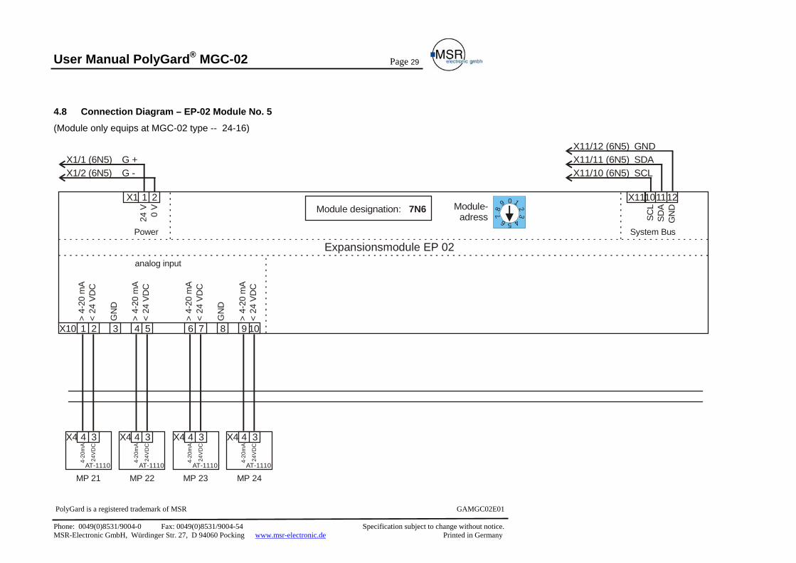
4.8 Connection Diagram – EP-02 Module No. 5
(Module only equips at MGC-02 type -- 24-16)
Power System Bus
Expansionsmodule EP 02
24 V
SCL
0 V
SDA
GN
D
X1 X11
1
4 4 4 4X4 X4 X4 X4
X10 742
3 3 3 3
8 1053 96
MP 21 MP 22 MP 23 MP 24AT-1110 AT-1110 AT-1110 AT-1110
> 4-
20 m
A4-
20m
A
4-20
mA
4-20
mA
4-20
mA
> 4-
20 m
A
> 4-
20 m
A
> 4-
20 m
A
< 24
VD
C24
VD
C
24V
DC
24V
DC
24V
DC
GN
D
GN
D
< 24
VD
C
< 24
VD
C
< 24
VD
C
1 10
X1/1 (6N5) X11/11 (6N5)X11/12 (6N5)
X1/2 (6N5) X11/10 (6N5) SCLSDAGND
2 1112
analog input
Module designation: 7N60
87
6 5 4
32
19Module-adress
G -G +

User Manual PolyGard® MGC-02
Page 30
PolyGard is a registered trademark of MSR GAMGC02E01 Phone: 0049(0)8531/9004-0 Fax: 0049(0)8531/9004-54 Specification subject to change without notice. MSR-Electronic GmbH, Würdinger Str. 27, D 94060 Pocking www.msr-electronic.de Printed in Germany
5 Start-up Operation
5.1 Start-up Before beginning of start-up the wiring of the Gas Controller including all field devices must be completely terminated!
If EP-02 modules is present, the module address must according to the following table on each module examined and if necessary corrected before switching on of supply voltage on.
The address adder for adjusting the module address is accessible after taking off the contact strip X1 (power).
Module designation (Yellow Label)
Module Address (Switch position)
MP No. Relay No.
3N2 1 5 to 8 5 to 10 4N3 2 9 to 12 11 to 15 5N4 3 13 to 16 16 to 20 6N5 4 17 to 20 ---- 7N6 5 21 to 24 ----
After switching On of the power supply and end of the Power On Time is the Gas Controller ready for use.
The Gas Controller is delivered with standard parameter and Set points. The registration the attached gas transmitter and the assignment of the alarm relays to the individual alarms must always occurs with start-up. Additional all other parameters are to be examined and adapted to the local conditions.
The standard parameter are to be taken from the following configuration and parameter card. We recommend to register the individual parameters and being into the map.
We recommending to check the parameters and set points after the following check list.

User Manual PolyGard® MGC-02
Page 31
PolyGard is a registered trademark of MSR GAMGC02E01 Phone: 0049(0)8531/9004-0 Fax: 0049(0)8531/9004-54 Specification subject to change without notice. MSR-Electronic GmbH, Würdinger Str. 27, D 94060 Pocking www.msr-electronic.de Printed in Germany
5.2 Checklist Start-up operation
Parameter Finish Announce existing EP-02 modules Time and Date Parameter Average Function Password level 1 (Customer Password) Function analog output Define failure relays Power On Time Service Phone No. Maintenance date
Parameter Finish Relay R 1 2 3 4 5 6 7 8 9 10 11 12 13 14 15 16 17 18 19 20
Relay Mode Function Static / Flash Latching Mode Horn function External Relay operation
Parameter Finish MP No. 1 2 3 4 5 6 7 8 9 10 11 12 13 14 15 16 17 8 19 20 21 22 23 24
MP Mode Gastype Measuring range MP- Signal Threshold 1 Threshold 2 Threshold 3 Threshold 4 Threshold 5 Hysteresis Delay ON time Delay OFF time C/A Mode Assigned Failure <> Alarm Assigned Alarm <> Alarm relay
System Parameter
Relay Parameter
MP Parameter

User Manual PolyGard® MGC-02
Page 32
PolyGard is a registered trademark of MSR GAMGC02E01 Phone: 0049(0)8531/9004-0 Fax: 0049(0)8531/9004-54 Specification subject to change without notice. MSR-Electronic GmbH, Würdinger Str. 27, D 94060 Pocking www.msr-electronic.de Printed in Germany
6 Configuration- and Parameter card. Commission: Project No. Customer: Service Technician Start-up - company Number MP Start-up - date:
6.1 Configurationscard Systemparameter
AV- Overlay Service Software Version
Mainten-ance date
Service Phone ppm Time AV-
Time
Time system
Costumers pass
Power On
Time
FailureRelay
Default 15 06.06.06 0853190040 120 120 1800 EU 1234 30 s 5
Analog output 1 Analog output 2 Registration Expansionsmodule EP-02 Calibration Calibration
EP-01 EP-02 EP-03 EP-04 EP-05 Mode = 4 = 20 Mode = 4 = 20Not active Not active Not active Not active Not active Max. 4.0 20.0 Max. 4.0 20.0
6.2 Configurationscard Alarmrelay
External Relay No.
Mode Static Flash
Latching mode
Horn Function ON OFF
Time Quitt DI DI DI Default Energezid 0 s No 0 0 0 0 0
R01 R02 R03 R04 R05 R06 R07 R08 R09 R10 R11 R12 R13 R14 R15 R16 R17 R18 R19 R20

User Manual PolyGard® MGC-02
Page 33
PolyGard is a registered trademark of MSR GAMGC02E01 Phone: 0049(0)8531/9004-0 Fax: 0049(0)8531/9004-54 Specification subject to change without notice. MSR-Electronic GmbH, Würdinger Str. 27, D 94060 Pocking www.msr-electronic.de Printed in Germany
6.3 Configurationscard Measuring Parameter
Thresholds Hyst Delay time (sec.)
CV/AV
Assigned MP fault < >Alarm Assigned Alarm <> Alarmrelay AO MP No.
MP Status
Gas type
Measuring range
MP-Signal
A1 A2 A3 A4 A5 ON OFF A1 A2 A3 A4 A5 A1 A2 A3 A4 A5 De
faultNot
activeCO 300 Linear 40 80 100 120 300 15 0 0 AV 1 1 0 0 0 R1 R2 R3 R4 -- 0
01 02 03 04 05 06 07 08 09 10 11 12 13 14 15 16 17 18 19 20 21 22 23 24

User Manual PolyGard® MGC-02
Page 34
PolyGard is a registered trademark of MSR GAMGC02E01 Phone: 0049(0)8531/9004-0 Fax: 0049(0)8531/9004-54 Specification subject to change without notice. MSR-Electronic GmbH, Würdinger Str. 27, D 94060 Pocking www.msr-electronic.de Printed in Germany
7 Specifications Electrical
Power supply 110/230 VAC 50/60Hz; 24 VAC/DC -10% + 20%
Power Consumption (incl. max. AT) MGC-02-04-04-XX MGC-02-08-08-XX to MGC-02-12-12-XX MGC-02-16-16-XX to MGC-02-24-16-XX
13 W, 500 mA 27 W, 1100 mA 55 W, 2200 mA
Option Emergency power supply Supply duration 60 minutes
Analog Input (max. 24) 4 to 20 mA, overload and short circuit protected, input resistor 200 Ω
Power supply for external analog Transmitter 24 VDC max. 50 mA / channel
Analog Output 4 to 20 mA, overload and short circuit protected, max. 500 Ω load
Alarm relay (max. 20) 250 VAC, 5 A, potentialfree, DPDT Failure relay 250 VAC, 5 A, potentialfree, DPDT Option Buzzer - Sound pressure 85 dB (Distance 300 mm) - Frequency 3,5 kHz Visualization Display Two lines, each 16 characters, illumination. Status LED Yellow = Status Alarm; Red = Failure Operation 6 Push button Gases 1
Gas Transmitter external CO, CO2, NO, NO2, NH3, O2, combustible and refrigerant Gases
Environmental Humidity 15 – 95 % r. F. non condensing Working temperature -5° C bis + 40° C Storage temperature 0° C bis + 40° C Physical Enclosure Plastic housing with view cover Color RAL 7035 (gray) Protection IP 65 Weight MGC-02-04-04XX MGC-02-08-08 to MGC-02-12-12 MGC-02-16-16 to MGC-02-20-16 MGC-02-24-16
2,7 kg 4,0 kg 6,0 kg 7,5 kg
Mounting Wall mounting Cable entry M 16; M 20; M 25 Wire connection: Power supply Relay Input
Screw type: 2,5 mm2 Carge clamp: min. 0,5 mm2, max. 1,5 mm2 Carge clamp: min. 0,5 mm2, max. 1,5 mm2
Dimensions: MGC-02-04-04XX MGC-02-08-08 to MGC-02-12-12 MGC-02-16-16 to MGC-02-20-16 MGC-02-24-16
(W x H x D) 298 x 260 x 140 mm (W x H x D) 298 x 420 x 140 mm (W x H x D) 298 x 570 x 140 mm (W x H x D) 410 x 655 x 140 mm
Guidelines EMV – Guidelines 89/336/EWG; CE Low voltage guideline 73/23/EWG VDI 20532
Warranty Two year material and workmanship
User Manual PolyGard® MGC-02
Page 35
PolyGard is a registered trademark of MSR GAMGC02E01 Phone: 0049(0)8531/9004-0 Fax: 0049(0)8531/9004-54 Specification subject to change without notice. MSR-Electronic GmbH, Würdinger Str. 27, D 94060 Pocking www.msr-electronic.de Printed in Germany
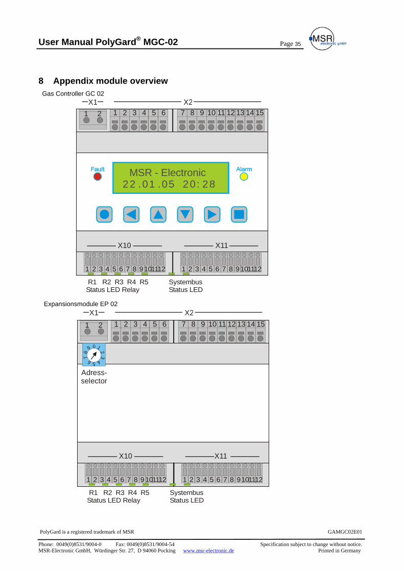
8 Appendix module overview Gas Controller GC 02 Expansionsmodule EP 02
MSR - Electronic22 .01 .05 20: 28
1
X10 X11
X22 2 3 4 5 6 7 8 9 10 11 12 13 14 151
1 2 3 4 5 6 7 8 9 101112 1 2 3 4 5 6 7 8 9 101112
X1
R1 R2 R3 R4 R5Status LED Relay
SystembusStatus LED
X10 X11
X21 2 2 3 4 5 6 7 8 9 10 11 12 13 14 151
0
87
6 5 4
32
19
X1
X10 X11
1 2 3 4 5 6 7 8 9 101112 1 2 3 4 5 6 7 8 9101112
R1 R2 R3 R4 R5Status LED Relay
SystembusStatus LED
Adress-selector

User Manual PolyGard® MGC-02
Page 36
PolyGard is a registered trademark of MSR GAMGC02E01 Phone: 0049(0)8531/9004-0 Fax: 0049(0)8531/9004-54 Specification subject to change without notice. MSR-Electronic GmbH, Würdinger Str. 27, D 94060 Pocking www.msr-electronic.de Printed in Germany
9 Notes and General Information It is important to read user manual thoroughly abd clearly understand the information and instructions. The PolyGard® - MGC-02 Gas monitoring, control and alarm system must be used within product specification capabilities. The appropriate operating and maintenance instructions and recommendations must be followed.
Due to ongoing product development, MSR reserves the right to change specifications without notice. The information contained herein is based upon data considered to be accurate. However, no guarantee is expressed or implied regarding the accuracy of this data.
9.1 Intended product application The PolyGard® MGC-02 are designed and manufactured for control applications for energy savings and OSHA air quality compliance in commercial buildings and manufacturing plants (i.e.,detection and automatic exhaust fan control for automotive maintenance facilities, enclosed parking garages, engine repair shops, warehouses with forklifts, fire stations, tunnels, etc.).
9.2 Installers` responsibilities It is the installer`s responsibility to ensure that all PolyGard® MGC-02 are installed in compliance with all national and local codes and OSHA requirements. Installation should be implemented only by individuals familiar with proper installation techniques and with codes, standards and proper safety procedures for control installations and the latest edition of the National Electrical Code (ANSI/NFPA70). It is also essential to strictly follow all instructions as provided in the user manual.
9.3 Maintenance It is recommended that the PolyGard® MGC-02 performance check is done on a routine schedule. Any performance deviations may be serviced based on needed requirements.
9.4 Limited warranty MSR warrant the PolyGard® MGC-02 for a period of two (2) years from the date of shipment against defects in material or workmanship. Should any evidence of defects in material or workmanship occur during the warranty period, MSR will repair or replace the product at their own discretion, without charge.
This warranty does not apply to units that have been altered, had repair attempted, or been subjected to abuse, accidental or otherwise. The above warranty is in lieu of all other express warranties, obligations or liabilities.
This warranty extends only to the PolyGard® MGC-02. MSR shall not be liable for any incidental or consequential damages arising out of or related to the use of the PolyGard® MGC-02.