Embed Size (px)
Citation preview

Analog Devices Welcomes Hittite Microwave Corporation
NO CONTENT ON THE ATTACHED DOCUMENT HAS CHANGED
www.analog.com www.hittite.com

THIS PAGE INTENTIONALLY LEFT BLANK

HMC987LP5E Evaluation Kit
User ManualSoftware & Hardware Installation
20 Alpha Road Chelmsford, MA 01824Phone: 978-250-3343 • Fax: 978-250-3373 • [email protected]
Order On-Line at: www.hittite.com Receive the latest product releases - click on “My Subscription”
Analog, Digital & Mixed-Signal ICs, Modules, Subsystems & Instrumentation
Part #
140-00037-00Rev. B - v01.0711ECN# CP111107

2
Rev. B - v01.0711
Order On-Line: www.hittite.com. For technical application questions: Tel: 978-250-3343 or [email protected]
HMC987LP5E Evaluation Kit User Manual
NoticeHittite Microwave Corporation has prepared this manual for use by Hittite personnel and customers as a guide for the proper instal-
lation, operation, and maintenance of Hittite equipment and computer programs. The drawings, specifications, and information con-
tained herein are the property of Hittite Microwave Corporation, and any unauthorized use or disclosure of these drawings, specifica-
tions, and information is prohibited; they shall not be reproduced, copied, or used in whole or in part as the basis for manufacture or
sale of the equipment or software programs without the prior written consent of Hittite Microwave Corporation.
Table of Contents
1. Introduction . . . . . . . . . . . . . . . . . . . . . . . . . . . . . . . . . . . . . . . . . . . . . . . . . . . . . . . . . . . . . . 32. Package Contents . . . . . . . . . . . . . . . . . . . . . . . . . . . . . . . . . . . . . . . . . . . . . . . . . . . . . . . . . 32.1 Hardware. . . . . . . . . . . . . . . . . . . . . . . . . . . . . . . . . . . . . . . . . . . . . . . . . . . . . . . . . . . . . . . . . 32.2 Software . . . . . . . . . . . . . . . . . . . . . . . . . . . . . . . . . . . . . . . . . . . . . . . . . . . . . . . . . . . . . . . . . 33. Operating Environment. . . . . . . . . . . . . . . . . . . . . . . . . . . . . . . . . . . . . . . . . . . . . . . . . . . . . 34. Setup and Installation . . . . . . . . . . . . . . . . . . . . . . . . . . . . . . . . . . . . . . . . . . . . . . . . . . . . . . 34.1 User Provided Equipment . . . . . . . . . . . . . . . . . . . . . . . . . . . . . . . . . . . . . . . . . . . . . . . . . . . 34.2 Hardware Setup . . . . . . . . . . . . . . . . . . . . . . . . . . . . . . . . . . . . . . . . . . . . . . . . . . . . . . . . . . . 44.2.1 Parallel Port Control Setup. . . . . . . . . . . . . . . . . . . . . . . . . . . . . . . . . . . . . . . . . . . . . . . . . . 44.2.2 SPI Control . . . . . . . . . . . . . . . . . . . . . . . . . . . . . . . . . . . . . . . . . . . . . . . . . . . . . . . . . . . . . . . 54.2.2.1 Software Installation . . . . . . . . . . . . . . . . . . . . . . . . . . . . . . . . . . . . . . . . . . . . . . . . . . . . . . . 64.3 Evaluation Board Configuration. . . . . . . . . . . . . . . . . . . . . . . . . . . . . . . . . . . . . . . . . . . . . . 74.3.1 Single-Ended Input Configuration. . . . . . . . . . . . . . . . . . . . . . . . . . . . . . . . . . . . . . . . . . . . 74.3.2 Single-Ended Output Configuration . . . . . . . . . . . . . . . . . . . . . . . . . . . . . . . . . . . . . . . . . . 75. Using the HMC987LP5E Evaluation Software . . . . . . . . . . . . . . . . . . . . . . . . . . . . . . . . . . 75.1 HMC987LP5E GUI . . . . . . . . . . . . . . . . . . . . . . . . . . . . . . . . . . . . . . . . . . . . . . . . . . . . . . . . . 9
3
Rev. B - v01.0711
Order On-Line: www.hittite.com. For technical application questions: Tel: 978-250-3343 or [email protected]
HMC987LP5E Evaluation Kit User Manual
1. Introduction
This document describes the functionality of the HMC987LP5E Evaluation Kit. The HMC987LP5E Evaluation board can be controlled via parallel port or SPI (Serial Port Interface). Parallel port control is implemented by simple jumper settings on the evaluation board. Serial Port interface offers more flexibility. This HMC987LP5E Evaluation Kit also includes the PC compatible software with Graphical User Interface (GUI), and software drivers necessary for Serial Port Interface, allowing the user to read from and write to all device registers, set gain levels and save & recall device configurations.
Note: For most up-to-date software download and information please visit www.hittite.com.
2. Package Contents
2.1 Hardware
Verify that all the items listed in Table 1 are included in the shipment.
Item Quantity
HMC987LP5E Evaluation Board 1
USB Interface Board 1
6’ USB A Male to USB B Male Cable 1
CD ROM (Contains User Manual and software) 1
Table 1: Packing List2.2 Software
The HMC987LP5E Evaluation Software enables users to communicate with and control HMC987LP5E Evaluation Board with their PC, and observe full functionality and performance of the HMC987LP5E.
3. Operating Environment
This evaluation kit is designed for use in a laboratory setting at ambient room temperature (25°C) and is not protected against moisture. The USB Interface Board has an ESD rating of +/-3000V, however the HMC987LP5E may have a lower rating (check the product’s datasheet for its specific ESD rating). Use appropriate ESD procedures and precautionary measures when handling all electronic hardware.
4. Setup and Installation
4.1 User Provided Equipment
In addition to the items provided in the evaluation kit, the user must provide the following equipment to communicate with the device under test.
• DC Power Supply
• DC Cables
• Signal source Generator
• Computer (PC) with Standard USB port if SPI control of the HMC987LP5E is desired.
For detail specifications regarding operating system and software requirements please visit www.hittite.com

4
Rev. B - v01.0711
Order On-Line: www.hittite.com. For technical application questions: Tel: 978-250-3343 or [email protected]
HMC987LP5E Evaluation Kit User Manual
4.2 Hardware Setup
The HMC987LP5E can be controlled via the parallel port or the SPI (Serial Port Interface). More information is available in the HMC987LP5E datasheet.
4.2.1 Parallel Port Control Setup
Setup all hardware according to Figure 1.
• Apply 4 V to 5 V to TP1 (TP2 is GND) on HMC987LP5E eval board. Supply current should be ~390 mA.
• Ensure jumper J7 is off, to enable parallel mode of the HMC987LP5E (PMODE_SEL = 1).
• Any enabled outputs that are not used should be terminated with a 50 Ω termination to ground.
• Jumpers J5 (SCLK), J6 (SDI), and J10 (SEN) are used to enable individual LVPECL outputs accord-ing to the following truth table:
Table 2. HMC987LP5E Parallel Port Output Control Truth Table
SCLK, SDI, SEN Enabled Outputs
000 OUT2
001 OUT2 + OUT7
010 OUT2 + OUT7 + OUT4
011 OUT2 + OUT7 + OUT4 + OUT6
100 OUT2 + OUT7 + OUT4 + OUT6 + OUT5 + OUT5
101 OUT2 + OUT7 + OUT4 + OUT6 + OUT5 + OUT5 + OUT3
110 OUT2 + OUT7 + OUT4 + OUT6 + OUT5 + OUT5 + OUT3 + OUT8
111 OUT2 + OUT7 + OUT4 + OUT6 + OUT5 + OUT5 + OUT3 + OUT8 + OUT1
Note that jumper ON pulls the signal to ground (0 V).
• The RF Buffer Enable is controlled from jumper J9. Installing the jumper pulls the enable to 0 - dis-abling the buffer. If the jumper is open, the buffer is enabled at maximum gain.
Note that the HMC987LP5E evaluation board includes a very low noise HMC987LP3E regulator. It is programmed (via resistors) to take in a voltage from 4.0 V to 5 V and generate the 3.3 V required for the HMC987LP5E.

5
Rev. B - v01.0711
Order On-Line: www.hittite.com. For technical application questions: Tel: 978-250-3343 or [email protected]
HMC987LP5E Evaluation Kit User Manual
Figure 1.
SLCKSDI
SEN
Parallel Control
HMC987LP5E Eval Board Parallel Port Control Test Setup
4.2.2 SPI Control
Setup all hardware according to Figure 2.
• Connect the USB board to HMC987LP5E eval board.
• Connect the USB cable to USB board.
• Apply 4 V to 5 V to TP1 (TP2 is GND) on HMC987LP5E eval board. Supply current should be ~395 mA.
• Use a jumper on J7 to disable Parallel Mode of the HMC987LP5E.
• Any enabled outputs that are not used should be terminated with a 50 Ω termination to ground.
6
Rev. B - v01.0711
Order On-Line: www.hittite.com. For technical application questions: Tel: 978-250-3343 or [email protected]
HMC987LP5E Evaluation Kit User Manual
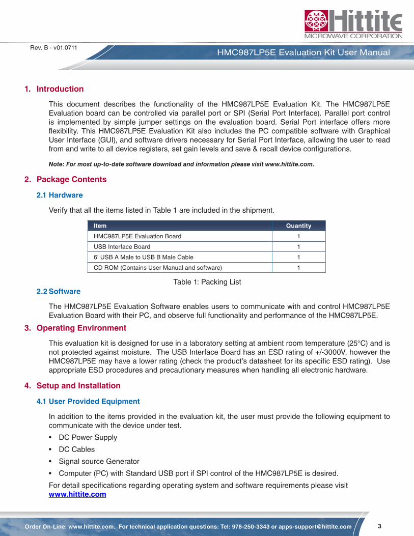
Figure 2. HMC987LP5E Eval Board SPI Control Test Setup
4.2.2.1 Software Installation
Note: Installing/Uninstalling the HMC987LP5E Evaluation Software requires administrative privileges
To install/uninstall HMC987LP5E Evaluation Software, double click on “HMC987LP5E Eval Software Installer.exe” that was downloaded from www.hittite.com, or provided with a CD, and follow the installation/uninstallation wizard.
7
Rev. B - v01.0711
Order On-Line: www.hittite.com. For technical application questions: Tel: 978-250-3343 or [email protected]
HMC987LP5E Evaluation Kit User Manual
4.3 Evaluation Board Configuration
The HMC987LP5E Evaluation Board schematic shows various input/output configurations. Default configurations are populated, and optional ones (labeled ‘depop’) are not populated. HMC987LP5E evaluation board is configured for differential drive, with AC coupling on both the input and output, by default. Components that are not populated on the HMC987LP5E evaluation board are not included in the evaluation kit.
For low frequency signals ( < 500 MHz) the 100 pF DC blocking capacitors on input and output should be increased.
Detailed information about various input/output HMC987LP5E interface configuration options are available in the HMC987LP5E datasheet.
4.3.1 Single-Ended Input Configuration
Hardware evaluation board changes are required to configure the HMC987LP5E evaluation board for single-ended input operation.
To configure HMC987LP5E evaluation board for single-ended input operation simply populate C104 with a 1 nF capacitor, and remove C12. Drive input CLKP (J1), and CLKN (J2) is AC grounded.
4.3.2 Single-Ended Output Configuration
When measuring single-ended, ensure that the other unused output is terminated with 50 Ω to ground.
5. Using the HMC987LP5E Evaluation Software
1. Ensure that the USB interface hardware is connected to the evaluation board, and that the HMC987LP5E is powered.
2. Launch HMC987LP5E Evaluation Software by selecting on “Hittite BUFFER Eval Software Vx.exe” from the Program Files menu of your computer. The main window should open. See Figure 3 below.

8
Rev. B - v01.0711
Order On-Line: www.hittite.com. For technical application questions: Tel: 978-250-3343 or [email protected]
HMC987LP5E Evaluation Kit User Manual
Figure 3. HMC FANOUT BUFFER Control Software
3. From this window select the HMC987LP5E from the drop down menu and press “Done” and the following window appears.
9
Rev. B - v01.0711
Order On-Line: www.hittite.com. For technical application questions: Tel: 978-250-3343 or [email protected]
HMC987LP5E Evaluation Kit User Manual
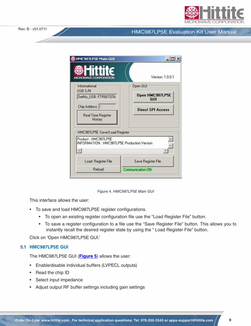
Figure 4. HMC987LP5E Main GUI
This interface allows the user:
• To save and load HMC987LP5E register configurations.
• To open an existing register configuration file use the “Load Register File” button.
• To save a register configuration to a file use the “Save Register File” button. This allows you to instantly recall the desired register state by using the “ Load Register File” button.
Click on ‘Open HMC987LP5E GUI.’
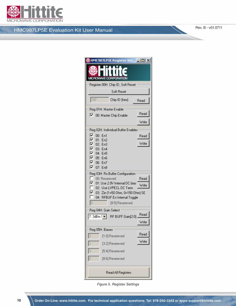
5.1 HMC987LP5E GUI
The HMC987LP5E GUI (Figure 5) allows the user:
• Enable/disable individual buffers (LVPECL outputs)
• Read the chip ID
• Select input impedance
• Adjust output RF buffer settings including gain settings
10
Rev. B - v01.0711
Order On-Line: www.hittite.com. For technical application questions: Tel: 978-250-3343 or [email protected]
HMC987LP5E Evaluation Kit User Manual
Figure 5. Register Settings

11
Rev. B - v01.0711
Order On-Line: www.hittite.com. For technical application questions: Tel: 978-250-3343 or [email protected]
HMC987LP5E Evaluation Kit User Manual
5.2 Direct Register Access
• “Direct SPI Access” button in the ‘HMC987LP5E Main GUI’ provides direct register read/write capabil-ity (Figure 6).
Figure 6. Direct SPI Access
6. Technical Support
Please contact [email protected] for any questions. Hittite Microwave provides local direct sup-port in many areas around the world. Please see the “Contact Us” page at www.hittite.com.

20 Alpha Road Chelmsford, MA 01824Phone: 978-250-3343 • Fax: 978-250-3373 • [email protected]
Order On-Line at: www.hittite.com Receive the latest product releases - click on “My Subscription”


![INDEX [link.springer.com]978-0-306-48134-5/1.pdf · 314 PHILOSOPHY, PSYCHOLOGY, AND PSYCHOLOGISM anthropological logic, 85, 86, 88 anthropomorphism, 171, 250 anti-descriptivism, 54;](https://img.pdfslide.us/doc/110x75/5c6bf20609d3f2a1458c2a2e/index-link-978-0-306-48134-51pdf-314-philosophy-psychology-and-psychologism.jpg)