Embed Size (px)
Citation preview
Int. J. Nav. Archit. Ocean Eng. (2013) 5:580~597 http://dx.doi.org/10.2478/IJNAOE-2013-0155
pISSN: 2092-6782, eISSN: 2092-6790
ⓒSNAK, 2013
Corresponding author: Yooil Kim, e-mail: [email protected] This is an Open-Access article distributed under the terms of the Creative Commons Attribution Non-Commercial License (http://creativecommons.org/licenses/by-nc/3.0) which permits unrestricted non-commercial use, distribution, and reproduction in any medium, provided the original work is properly cited.
An experimental study on fatigue performance of cryogenic metallic materials for IMO type B tank
Jin-Sung Lee1, Won-Hyo You2, Chang-Hyuk Yoo1, Kyung-Su Kim1 and Yooil Kim1
1Department of Naval Architecture and Ocean Engineering, Inha University, Incheon, Korea 2Hyundai Steel Co., Ltd., Dangjin, Korea
ABSTRACT: Three materials SUS304, 9% Ni steel and Al 5083-O alloy, which are considered possible candidate for International Maritime Organization (IMO) type B Cargo Containment System, were studied. Monotonic tensile, fatigue, fatigue crack growth rate and Crack Tip Opening Displacement tests were carried out at room, intermediate low (-100
oC) and cryogenic (-163 oC) temperatures. The initial yield and tensile strengths of all materials tended to increase with decreasing temperature, whereas the change in elastic modulus was not as remarkable. The largest and smallest im-provement ratio of the initial yield strengths due to a temperature reduction were observed in the SUS304 and Al 5083-O alloy, respectively. The fatigue strengths of the three materials increased with decreasing temperature. The largest increase in fatigue strength was observed in the Al 5083-O alloy, whereas the 9% Ni steel sample showed the smallest increase. In the fatigue crack growth rate test, SUS304 and Al 5083-O alloy showed a decrease in the crack propaga-tion rate, due to decrease in temperature, but no visible improvement in da/dN was observed in the case of 9% Ni steel. In the Crack Tip Opening Displacement (CTOD) test, CTOD values were converted to critical crack length for the comparison with different thickness specimens. The critical crack length tended to decrease in the case of SUS304 and increase for the Al 5083-O alloy with decreasing temperature. In case of 9% Ni steel, change of critical crack length was not observed due to temperature decrease. In addition, the changing material properties according to the tempe-rature of the LNG tank were analyzed according to the international code for the construction and equipment of ships carrying liquefied gases in bulk (IGC code) and the rules of classifications.
KEY WORDS: Cryogenic temperature; Liquefied natural gas (LNG); IMO type B tank; Fatigue; Crack tip opening displacement; SUS304; Al5083-O; 9% Ni.
INTRODUCTION
Recently, sloshing is deemed to be one of the most important design aspects when it comes to the reliable design of cargo containment system of the offshore LNG units, such as LNG Floating Production Storage & Offloading (FPSO) or Floating Storage and Regasification Unit (FSRU). Unlike seagoing LNG carriers where filling ratio is limited to remain above or below a certain filling level, offshore LNG units should be allowed to operate without any filling limitation. It entails a partial filling condition inside the cargo tank and the sloshing impact pressure induced by liquid cargo motion tends to increase compared to those under high or low filling conditions. The relatively large tank size and the above mentioned unlimited filling ratio require-

Int. J. Nav. Archit. Ocean Eng. (2013) 5:580~597 581
ments necessitate the cargo containment system of LNG FPSO be designed with care. Normally, sloshing excitation and resul-ting impact pressure is known to become more critical when the vessel is exposed to the beam sea condition. The roll motion of the vessel is easily excited and it is highly likely to see resonance behavior between tank motion and liquid cargo motion, eventually leading to a critical situation. Especially, with traditional tank size, the resonance period of fluid-filled tank stays within the period range where ocean wave energy is high.
IMO type B tank, which is a type of LNG cargo containment system specified by IMO rule, is deemed to be a good alter-native concept of LNG cargo containment system from the perspective of sloshing. The independent tank is arranged inside cargo hold space of the ship and the outer surface of the tank is insulated to keep the cryogenic temperature from conducting to the hull structure. Due to the strong internal members, such as web frames and large longitudinal girders, type B tank is thought to be very tolerant against the sloshing phenomenon. All those internal members work as the baffle so that the liquid motion inside cargo tank hardly can get violent.
The cryogenic metallic materials, such as stainless steel (SUS304), nickel alloy steel (9% Ni steel) and aluminum alloy (Al 5083-O alloy) are being considered as possible candidates for IMO type B CCS materials. IMO type B tank requires extensive engineering verification during the design phase, such as leak rate calculation through crack propagation analysis together with fracture analysis. To meet the target, it is very important to evaluate the material behavior under cryogenic environment. There-fore, material testing should be carried out to obtain accurate material property.
Regarding the material property test for the applicability of various metallic materials to the cryogenic environment, not so many research works have been done and published. To note some them, Mukai and Nishinura (1990) investigated the mecha-nical properties of SUS304 under cryogenic thermal cycles. They claimed that SUS304 has the potential to cause thermal fatigue failure under cryogenic environment. Jung et al. (1997) evaluated the fracture toughness in X-grooved weld Heat Af-fected Zone (HAZ) of 9% Ni steel through CTOD test. Additionally, microstructure of HAZ was observed and analyzed. The fatigue crack growth rate and CTOD tests on SUS304 and weld metal were studied by Back et al. (2001). According to test results of Back et al. (2001), the fatigue crack growth rates and the CTOD values decreased with decreasing test temperature. The fatigue crack growth rate of Al5083-O alloy was invested using nondestructive evaluation by Nam (2001). He evaluated the fatigue crack growth rate properties and life prediction of Al5083-O alloy. Zhou et al. (2006) studied the fatigue properties of friction stir welds in Al5083-O alloy. They investigated the fatigue property of Al5083-O alloy. Additionally, It was iden-tified that friction stir weld has a longer fatigue life than MIG-pulse weld. Yoo et al. (2011) carried out experiments, such as monotonic tensile test, fatigue test, crack growth rate test and CTOD test for material properties of the cryogenic metallic materials, SUS304, 9% Ni steel, Al5083-O alloy. They identified material properties of the cryogenic metallic materials and simply compared material properties. However, the comparison of CTOD values was not made because CTOD specimens of each material had different thickness, which is actually used thickness of each material, for practical study. In addition, eco-nomic perspective was not considered. This paper extended the works of Yoo et al. (2011) by adding the systematic comparison among different materials in terms of their basic mechanical properties and proposes some guidelines for the material selection for IMO type B tank.
In this paper, extensive experimental works have been carried out in order to figure out the pros and cons of different metallic materials such as SUS304, 9% Ni steel, Al5083-O alloy from the economic perspective. Monotonic tensile test, fatigue test, crack growth rate and CTOD test have been performed for the three cryogenic metallic materials and comparison was made among them to find the best candidate for the material of IMO type B tank. Specially, Critical crack lengths were calculated for the comparison of CTOD values, which is obtained from difference thickness specimens. This study provides the basic material data for the decisions making regarding the material for IMO type B tank.
EXPERIMENT
Specimen type and dimensions
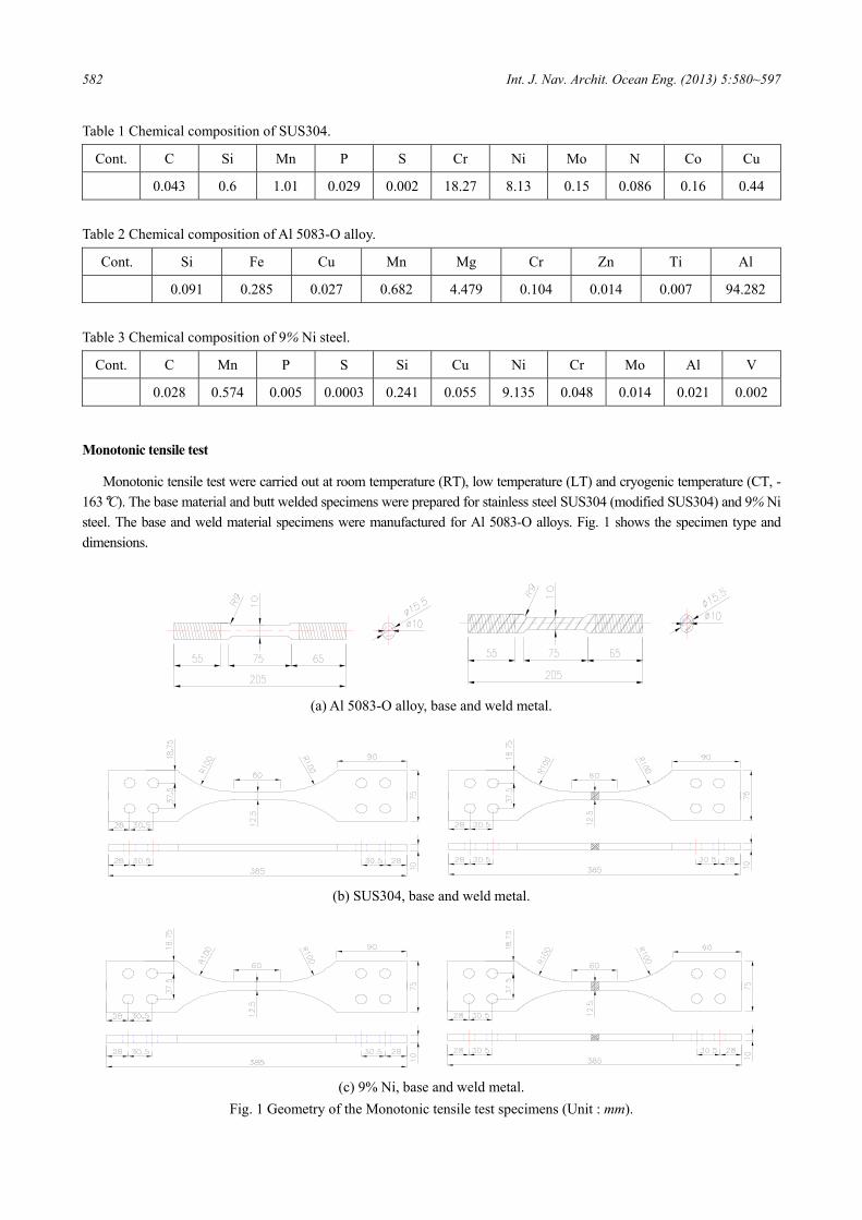
In these experiments, monotonic tensile, fatigue test specimens were prepared form three materials considered possible candidates for Type B LNG tanks. Figs. 1-5 show the specimen shapes and dimensions of each material. In addition, the wel-ding form and sample direction are described. Chemical compositions of specimens were shown in Tables 1-3.
582 Int. J. Nav. Archit. Ocean Eng. (2013) 5:580~597
Table 1 Chemical composition of SUS304.
Cont. C Si Mn P S Cr Ni Mo N Co Cu
0.043 0.6 1.01 0.029 0.002 18.27 8.13 0.15 0.086 0.16 0.44
Table 2 Chemical composition of Al 5083-O alloy.
Cont. Si Fe Cu Mn Mg Cr Zn Ti Al
0.091 0.285 0.027 0.682 4.479 0.104 0.014 0.007 94.282
Table 3 Chemical composition of 9% Ni steel.
Cont. C Mn P S Si Cu Ni Cr Mo Al V
0.028 0.574 0.005 0.0003 0.241 0.055 9.135 0.048 0.014 0.021 0.002
Monotonic tensile test
Monotonic tensile test were carried out at room temperature (RT), low temperature (LT) and cryogenic temperature (CT, -163°C). The base material and butt welded specimens were prepared for stainless steel SUS304 (modified SUS304) and 9% Ni steel. The base and weld material specimens were manufactured for Al 5083-O alloys. Fig. 1 shows the specimen type and dimensions.
(a) Al 5083-O alloy, base and weld metal.
(b) SUS304, base and weld metal.
(c) 9% Ni, base and weld metal.
Fig. 1 Geometry of the Monotonic tensile test specimens (Unit : mm).
Int. J. Nav. Archit. Ocean Eng. (2013) 5:580~597 583
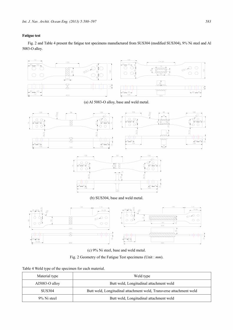
Fatigue test
Fig. 2 and Table 4 present the fatigue test specimens manufactured from SUS304 (modified SUS304), 9% Ni steel and Al 5083-O alloy.
(a) Al 5083-O alloy, base and weld metal.
(b) SUS304, base and weld metal.
(c) 9% Ni steel, base and weld metal.
Fig. 2 Geometry of the Fatigue Test specimens (Unit : mm).
Table 4 Weld type of the specimen for each material.
Material type Weld type
Al5083-O alloy Butt weld, Longitudinal attachment weld
SUS304 Butt weld, Longitudinal attachment weld, Transverse attachment weld
9% Ni steel Butt weld, Longitudinal attachment weld
584 Int. J. Nav. Archit. Ocean Eng. (2013) 5:580~597
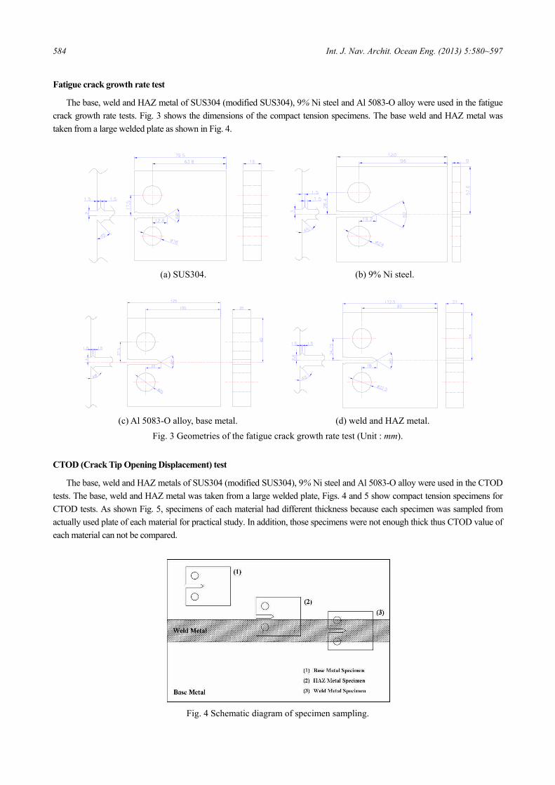
Fatigue crack growth rate test
The base, weld and HAZ metal of SUS304 (modified SUS304), 9% Ni steel and Al 5083-O alloy were used in the fatigue crack growth rate tests. Fig. 3 shows the dimensions of the compact tension specimens. The base weld and HAZ metal was taken from a large welded plate as shown in Fig. 4.
(a) SUS304. (b) 9% Ni steel.
(c) Al 5083-O alloy, base metal. (d) weld and HAZ metal.
Fig. 3 Geometries of the fatigue crack growth rate test (Unit : mm).
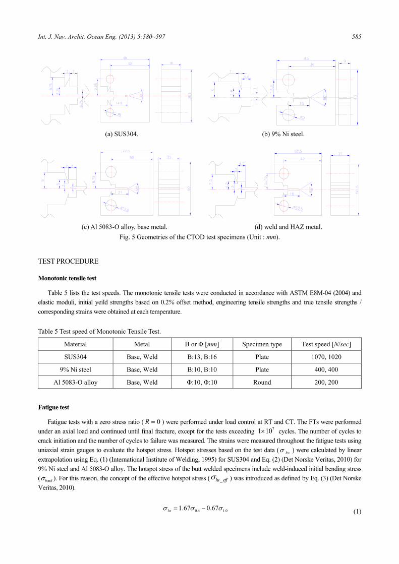
CTOD (Crack Tip Opening Displacement) test
The base, weld and HAZ metals of SUS304 (modified SUS304), 9% Ni steel and Al 5083-O alloy were used in the CTOD tests. The base, weld and HAZ metal was taken from a large welded plate, Figs. 4 and 5 show compact tension specimens for CTOD tests. As shown Fig. 5, specimens of each material had different thickness because each specimen was sampled from actually used plate of each material for practical study. In addition, those specimens were not enough thick thus CTOD value of each material can not be compared.
Fig. 4 Schematic diagram of specimen sampling.
Int. J. Nav. Archit. Ocean Eng. (2013) 5:580~597 585
(a) SUS304. (b) 9% Ni steel.
(c) Al 5083-O alloy, base metal. (d) weld and HAZ metal.
Fig. 5 Geometries of the CTOD test specimens (Unit : mm).
TEST PROCEDURE
Monotonic tensile test
Table 5 lists the test speeds. The monotonic tensile tests were conducted in accordance with ASTM E8M-04 (2004) and elastic moduli, initial yeild strengths based on 0.2% offset method, engineering tensile strengths and true tensile strengths / corresponding strains were obtained at each temperature.
Table 5 Test speed of Monotonic Tensile Test.
Material Metal B or Φ [mm] Specimen type Test speed [N/sec]
SUS304 Base, Weld B:13, B:16 Plate 1070, 1020
9% Ni steel Base, Weld B:10, B:10 Plate 400, 400
Al 5083-O alloy Base, Weld Φ:10, Φ:10 Round 200, 200
Fatigue test
Fatigue tests with a zero stress ratio ( 0R = ) were performed under load control at RT and CT. The FTs were performed under an axial load and continued until final fracture, except for the tests exceeding 71 10× cycles. The number of cycles to crack initiation and the number of cycles to failure was measured. The strains were measured throughout the fatigue tests using uniaxial strain gauges to evaluate the hotspot stress. Hotspot stresses based on the test data ( h sσ ) were calculated by linear extrapolation using Eq. (1) (International Institute of Welding, 1995) for SUS304 and Eq. (2) (Det Norske Veritas, 2010) for 9% Ni steel and Al 5083-O alloy. The hotspot stress of the butt welded specimens include weld-induced initial bending stress ( bendσ ). For this reason, the concept of the effective hotspot stress ( _hs effσ ) was introduced as defined by Eq. (3) (Det Norske Veritas, 2010).
0.4 1.01.67 0.67hsσ σ σ= − (1)

586 Int. J. Nav. Archit. Ocean Eng. (2013) 5:580~597
0.4 1.51.5 0.5hsσ σ σ= − (2)
_ 0.6hs eff mem bendσ σ σΔ =Δ − (3)
Fatigue crack growth rate test
The fatigue crack growth rate tests were carried out at RT, -100°C and -163°C. A Crack Opening Displacement (COD) gauge was installed on the front face next to the notch to measure the crack mouth opening displacement. Crack length and crack growth rate were calculated from measured crack opening displacement in real time. The distance between the load line and crack tip is a, W is specimen width. α is a devided by specimen width. The stress intensity factor range (∆K) for the com-pact specimen can be expressed as Eq. (4) (Anderson, 2005). Fatigue crack propagation is characterized by the Paris equation as shown in Eq. (5). Fatigue crack growth rate tests were performed under load control with a zero stress ratio (R=0) at RT, -100°C and -163°C. The Paris constants (C, m) were evaluated at each temperature.
( )( )2 3 4
32
(2 ) 0.886 4.64 13.32 14.72 5.61
PKB W
α α α α αα
Δ +Δ = + − + −
− (4)
( )/ mda dN C K= Δ (5)
Crack tip opening displacement test
The CTOD tests were carried out at RT(0°C), -100°C and -163°C. A COD gauge was installed on the load line to measure the Crack mouth opening displacment when specimen was fractured. The CTODs were calculated using Eqs. (6) and (7) (ASTM E1290, 2007 and BS 7448, 1997, respectively). Crack Tip Opening Displacement is related with stress intensity factor K, Poisson’s ratio υ, effective width of specimen W, elastic modulus E, mean original crack length a0 and 0.2% proof strength σYS.
( ) ( )202
0
1 0.462 0.46 0.56
p
YS
W a VK
E W a z
υδ
σ
− −= +
+ + (6)
( )( )
2 2
00
11
10.8 0.2
p
Y
K Am E zB W a
a W
υ ηδ
σ α
⎧ ⎫⎪ ⎪
−⎛ ⎞⎪ ⎪= +⎨ ⎬⎜ ⎟⎡ ⎤⎛ ⎞+⎝ ⎠⎪ ⎪− +⎢ ⎥⎜ ⎟⎪ ⎪+⎝ ⎠⎣ ⎦⎩ ⎭
(7)
TENSILE STRENGTH EVALUATION
Monotonic tensile test results and analysis
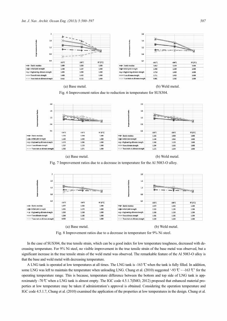
Figs. 6-8 show the improvement ratios of the elastic modulus, initial yield strength, engineering tensile strength, true tensile strength and true tensile strain due to a decrease in temperature for each material. The mechanical characteristics were nor-malized with regard to those at RT. Regardless of the type of material and metal (base or weld), a reduction in temperature gives rise to an increase in the initial yield strength, engineeirng tensile strength and true tensile strength.
Int. J. Nav. Archit. Ocean Eng. (2013) 5:580~597 587
(a) Base metal. (b) Weld metal.
Fig. 6 Improvement ratios due to reduction in temperature for SUS304.
(a) Base metal. (b) Weld metal.
Fig. 7 Improvement ratios due to a decrease in temperature for the Al 5083-O alloy.
(a) Base metal. (b) Weld metal.
Fig. 8 Improvement ratios due to a decrease in temperature for 9% Ni steel. In the case of SUS304, the true tensile strain, which can be a good index for low temperature toughness, decreased with de-
creasing temperature. For 9% Ni steel, no visible improvement in the true tensile strain of the base metal was observed, but a significant increase in the true tensile strain of the weld metal was observed. The remarkable feature of the Al 5083-O alloy is that the base and weld metal with decreasing temperature.
A LNG tank is operated at low temperatures at all times. The LNG tank is -163°C when the tank is fully filled. In addition, some LNG was left to maintain the temperature when unloading LNG. Chung et al. (2010) suggested ‘-93°C ~ -163°C’ for the operating temperature range. This is because, temperature difference between the bottom and top side of LNG tank is app-roximately -70°C when a LNG tank is almost empty. The IGC code 4.5.1.7(IMO, 2012) proposed that enhanced material pro-perties at low temperature may be taken if administration’s approval is obtained. Considering the operation temperature and IGC code 4.5.1.7, Chung et al. (2010) examined the application of the properties at low temperatures in the design. Chung et al.
588 Int. J. Nav. Archit. Ocean Eng. (2013) 5:580~597
(2010) handled only SUS304. On the other hand, three materials (SUS304, 9% Ni steel, Al 5083-O alloy) were handled in this paper.
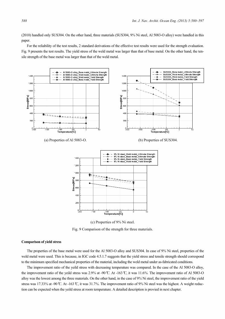
For the reliability of the test results, 2 standard derivations of the effective test results were used for the strength evaluation. Fig. 9 presents the test results. The yield stress of the weld metal was larger than that of base metal. On the other hand, the ten-sile strength of the base metal was larger than that of the weld metal.
(a) Properties of Al 5083-O. (b) Properties of SUS304.
(c) Properties of 9% Ni steel.
Fig. 9 Comparison of the strength for three materials.
Comparison of yield stress
The properties of the base metal were used for the Al 5083-O alloy and SUS304. In case of 9% Ni steel, properties of the weld metal were used. This is because, in IGC code 4.5.1.7 suggests that the yield stress and tensile strength should correspond to the minimum specified mechanical properties of the material, including the weld metal under as-fabricated conditions.
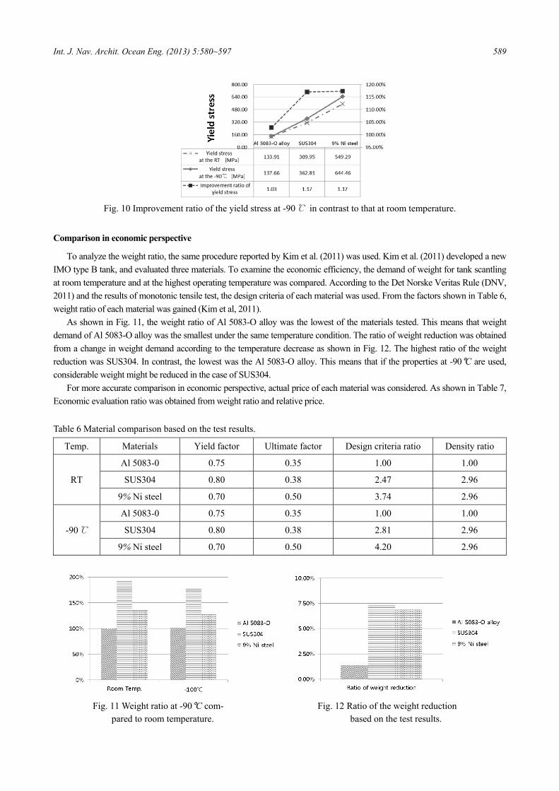
The improvement ratio of the yeild stress with decreasing temperature was compared. In the case of the Al 5083-O alloy, the improvement ratio of the yeild stress was 2.9% at -90°C. At -163°C, it was 11.6%. The improvement ratio of Al 5083-O alloy was the lowest among the three materials. On the other hand, in the case of 9% Ni steel, the improvement ratio of the yield stress was 17.33% at -90°C. At -163°C, it was 31.7%. The improvement ratio of 9% Ni steel was the highest. A weight reduc-tion can be expected when the yeild stress at room temperature. A detailed description is provied in next chapter.
Int. J. Nav. Archit. Ocean Eng. (2013) 5:580~597 589
Fig. 10 Improvement ratio of the yield stress at -90℃ in contrast to that at room temperature.
Comparison in economic perspective
To analyze the weight ratio, the same procedure reported by Kim et al. (2011) was used. Kim et al. (2011) developed a new IMO type B tank, and evaluated three materials. To examine the economic efficiency, the demand of weight for tank scantling at room temperature and at the highest operating temperature was compared. According to the Det Norske Veritas Rule (DNV, 2011) and the results of monotonic tensile test, the design criteria of each material was used. From the factors shown in Table 6, weight ratio of each material was gained (Kim et al, 2011).
As shown in Fig. 11, the weight ratio of Al 5083-O alloy was the lowest of the materials tested. This means that weight demand of Al 5083-O alloy was the smallest under the same temperature condition. The ratio of weight reduction was obtained from a change in weight demand according to the temperature decrease as shown in Fig. 12. The highest ratio of the weight reduction was SUS304. In contrast, the lowest was the Al 5083-O alloy. This means that if the properties at -90°C are used, considerable weight might be reduced in the case of SUS304.
For more accurate comparison in economic perspective, actual price of each material was considered. As shown in Table 7, Economic evaluation ratio was obtained from weight ratio and relative price.
Table 6 Material comparison based on the test results.
Temp. Materials Yield factor Ultimate factor Design criteria ratio Density ratio
RT
Al 5083-0 0.75 0.35 1.00 1.00
SUS304 0.80 0.38 2.47 2.96
9% Ni steel 0.70 0.50 3.74 2.96
-90℃
Al 5083-0 0.75 0.35 1.00 1.00
SUS304 0.80 0.38 2.81 2.96
9% Ni steel 0.70 0.50 4.20 2.96
Fig. 11 Weight ratio at -90°C com- Fig. 12 Ratio of the weight reduction
pared to room temperature. based on the test results.

590 Int. J. Nav. Archit. Ocean Eng. (2013) 5:580~597
Table 7 Economical efficiency.
Relative price Economic evaluation ratio
Al 5083-O alloy 1.00 1.00
SUS 304 0.69 1.21
9% Ni steel 0.85 1.06
FATIGUE STRENGTH EVALUATION
Fatigue test
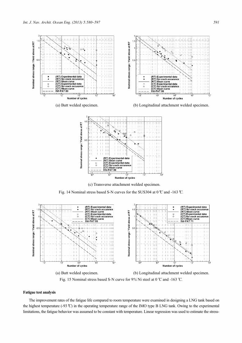
Figs. 13-15 shows the S-N curves, normalized by the yield stress at 0°C where the dashed black lines refer to IIW (IIW, 1995). The solid and dotted lines were obtained from regression analyses of the test data using Eq. (8) which used the same slope as the International Institute of Welding guidance (IIW, 1995), where the number of cycles to failure is N, ∆σ is stress range and intercept of log N-axis by S-N curves is log a . The solid and dotted lines are the regression lines of test data at 0°C and -163°C, respectively. The data points with the final fracture at more than ten million cycles were excluded from regression analyses. In Figs. 13-15, a nominal stress ( nσ ) was applid for the regression analysis.
log log 3logN a σ= − Δ (8)
Table 8 lists the improvement ratios of the fatigue strengths according to temperature reduction. The improvement ratio of both norminal stress based fatigue strength and effective hot spot stress based fatigue strength are calculated as shown in Table 8. Regardless of the materials and weld type, the temperature reduction resulted in increase in fatigue strength. The Al 5083-O alloy showed the highest increase in fatigue strength with decreasing temperature whereas 9% Ni steel showed the lowest increase.
Table 8 Improvement ratios of the fatigue strengths for three materials according to temperature reduction .
Material type Weld type nσ based hs effσ based
Al5083-O alloy Butt, Longi 1.838, 1.634 2.018, 1.875
SUS304 Butt, Longi, Trans. 1.476, 1.608, 1.684 1.4753, 1.511, 1.638
9% Ni steel Butt, Longi 1.342, 1.063 1.437, 1.089 In the case of the butt welded specimens, the Al 5083-O alloy shows the largest increase in fatigue strength, whereas smaller
increase were observed in the other two materials. Regarding the specimens with longitudinal attachments, the SUS304 and Al 5083-O alloy showed a larger increase in fatigue strength than 9% Ni steel.
(a) Butt welded specimen. (b) Longitudinal attachment welded specimen.
Fig. 13 Nominal stress based S-N curve for the Al 5083-O alloy at 0°C and -163°C.
Int. J. Nav. Archit. Ocean Eng. (2013) 5:580~597 591
(a) Butt welded specimen. (b) Longitudinal attachment welded specimen.
(c) Transverse attachment welded specimen.
Fig. 14 Nominal stress based S-N curves for the SUS304 at 0°C and -163°C.
(a) Butt welded specimen. (b) Longitudinal attachment welded specimen.
Fig. 15 Nominal stress based S-N curve for 9% Ni steel at 0°C and -163°C.
Fatigue test analysis
The improvement rates of the fatigue life compared to room temperature were examined in designing a LNG tank based on the highest temperature (-93°C) in the operating temperature range of the IMO type B LNG tank. Owing to the experimental limitations, the fatigue behavior was assumed to be constant with temperature. Linear regression was used to estimate the stress-
592 Int. J. Nav. Archit. Ocean Eng. (2013) 5:580~597
fatigue life curves at -93°C. Based on this result, the improvement ratios of the fatigue life were compared with the fatigue life at room temperature.
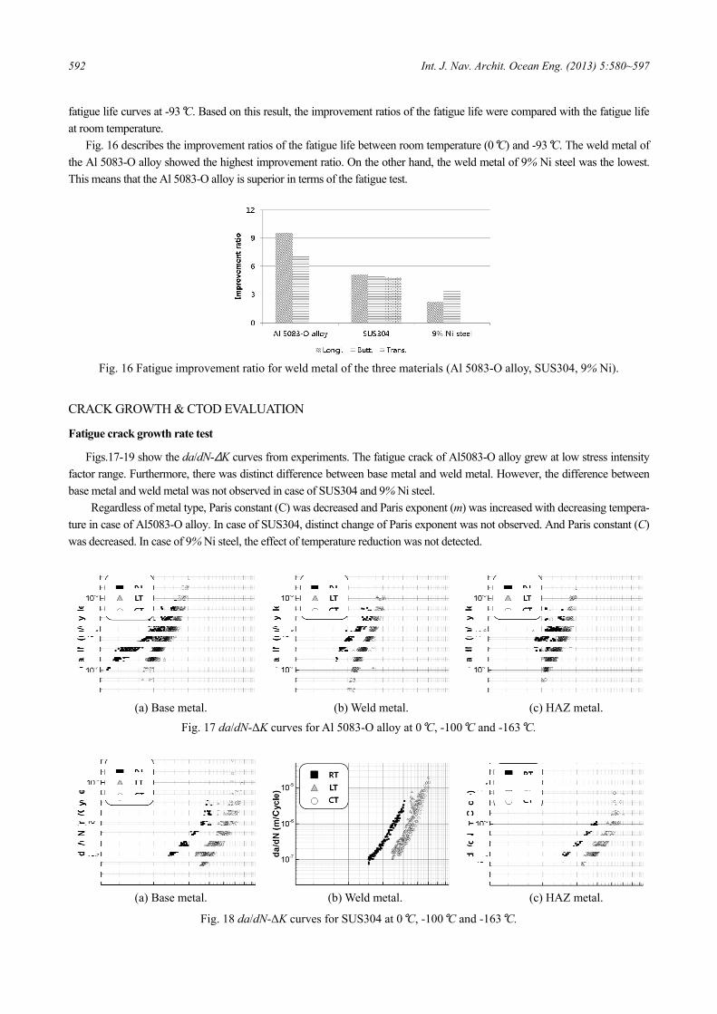
Fig. 16 describes the improvement ratios of the fatigue life between room temperature (0°C) and -93°C. The weld metal of the Al 5083-O alloy showed the highest improvement ratio. On the other hand, the weld metal of 9% Ni steel was the lowest. This means that the Al 5083-O alloy is superior in terms of the fatigue test.
Fig. 16 Fatigue improvement ratio for weld metal of the three materials (Al 5083-O alloy, SUS304, 9% Ni).
CRACK GROWTH & CTOD EVALUATION
Fatigue crack growth rate test
Figs.17-19 show the da/dN-ΔK curves from experiments. The fatigue crack of Al5083-O alloy grew at low stress intensity factor range. Furthermore, there was distinct difference between base metal and weld metal. However, the difference between base metal and weld metal was not observed in case of SUS304 and 9% Ni steel.
Regardless of metal type, Paris constant (C) was decreased and Paris exponent (m) was increased with decreasing tempera-ture in case of Al5083-O alloy. In case of SUS304, distinct change of Paris exponent was not observed. And Paris constant (C) was decreased. In case of 9% Ni steel, the effect of temperature reduction was not detected.
(a) Base metal. (b) Weld metal. (c) HAZ metal.
Fig. 17 da/dN-ΔK curves for Al 5083-O alloy at 0°C, -100°C and -163°C.
(a) Base metal. (b) Weld metal. (c) HAZ metal.
Fig. 18 da/dN-ΔK curves for SUS304 at 0°C, -100°C and -163°C.

Int. J. Nav. Archit. Ocean Eng. (2013) 5:580~597 593
(a) Base metal. (b) Weld metal. (c) HAZ metal.
Fig. 19 da/dN-ΔK curves for 9% Ni steel at 0°C, -100°C and -163°C.
The fatigue crack growth characteristics of three materials were compared, as shown in Fig. 20, using the decrease ratio of
the fatigue crack growth rates. In the case of Al 5083-O alloy and SUS304, the fatigue crack growth rates decresed sharply with decreasing temperature. In the case of 9% Ni steel, the fatigue crack growth rates showed only a small decrease. In addition, there was no distinct tendency. Therefore, the Al 5083-O alloy and SUS304 are superior in terms of the fatigue crack growth rate test.
Base metal [%] Weld metal [%] Base metal [%] Weld metal [%]
Al 5083-O alloy 5.90 0.89 Al 5083-O alloy 4.80 2.18
SUS304 14.78 9.45 SUS304 7.67 3.10
9% Ni 74.91 51.49 9% Ni 94.13 64.05
(a) Decrease ratios of FCGRT at -100°C. (b) Decrease ratios of FCGRT at -163°C.
Fig. 20 Decrease ratios of the fatigue crack growth rate based on the -100°C property.
Crack tip opening displacement test
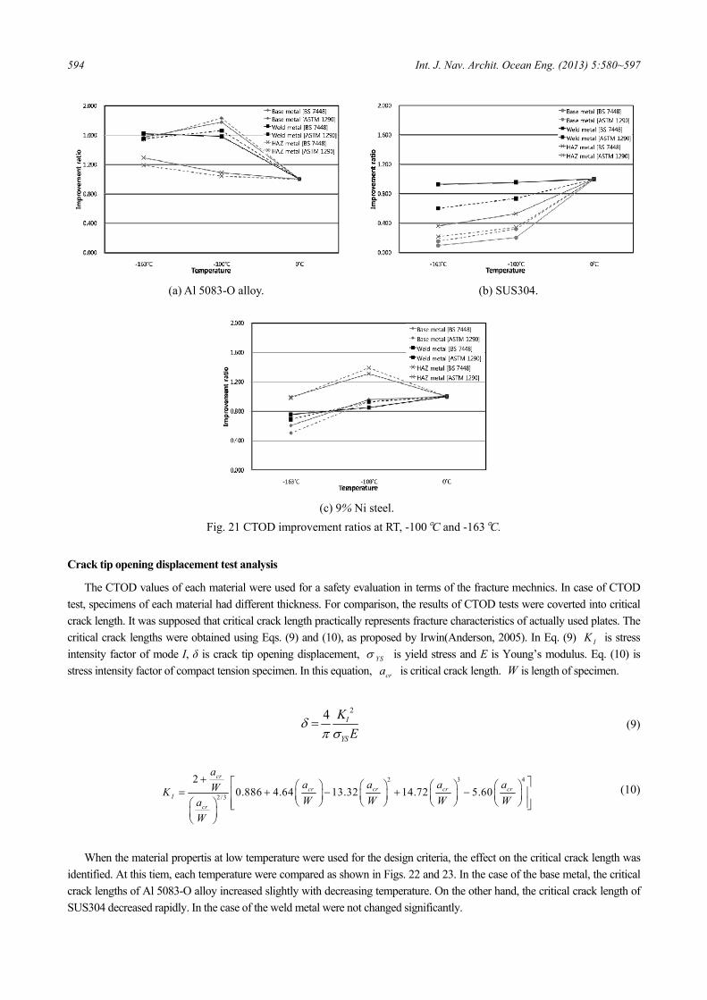
Fig. 21 shows the normalized CTODs of improvement ratios of the CTODs versus temperature. The CTODs at -100℃ and -163°C were normalized with respect to those at 0°C. For SUS304, the CTODs tended to decrease with decreasing temperature with the largest decrease in CTODs observed for the base metal. For 9% Ni steel, the base and weld metal showed a similar tendency, wheras the CTOD for the HAZ metal increased at -100°C compared with that at 0°C and -163°C. The CTODs for the Al 5083-O alloy tended to increase with decreasing temperature. The largest CTOD value was observed at -100°C for the base and weld metal, followed by a decrease at -163°C.
594 Int. J. Nav. Archit. Ocean Eng. (2013) 5:580~597
(a) Al 5083-O alloy. (b) SUS304.
(c) 9% Ni steel.
Fig. 21 CTOD improvement ratios at RT, -100°C and -163°C.
Crack tip opening displacement test analysis
The CTOD values of each material were used for a safety evaluation in terms of the fracture mechnics. In case of CTOD test, specimens of each material had different thickness. For comparison, the results of CTOD tests were coverted into critical crack length. It was supposed that critical crack length practically represents fracture characteristics of actually used plates. The critical crack lengths were obtained using Eqs. (9) and (10), as proposed by Irwin(Anderson, 2005). In Eq. (9) IK is stress intensity factor of mode I, δ is crack tip opening displacement, YSσ is yield stress and E is Young’s modulus. Eq. (10) is stress intensity factor of compact tension specimen. In this equation, cra is critical crack length. W is length of specimen.
24 I
YS
KE
δπ σ
= (9)
2 3 4
2/3
20.886 4.64 13.32 14.72 5.60
cr
cr cr cr crI
cr
aa a a aWKW W W Wa
W
+ ⎡ ⎤⎛ ⎞ ⎛ ⎞ ⎛ ⎞ ⎛ ⎞= + − + −⎢ ⎥⎜ ⎟ ⎜ ⎟ ⎜ ⎟ ⎜ ⎟⎝ ⎠ ⎝ ⎠ ⎝ ⎠ ⎝ ⎠⎛ ⎞ ⎢ ⎥⎣ ⎦
⎜ ⎟⎝ ⎠
(10)
When the material propertis at low temperature were used for the design criteria, the effect on the critical crack length was identified. At this tiem, each temperature were compared as shown in Figs. 22 and 23. In the case of the base metal, the critical crack lengths of Al 5083-O alloy increased slightly with decreasing temperature. On the other hand, the critical crack length of SUS304 decreased rapidly. In the case of the weld metal were not changed significantly.

Int. J. Nav. Archit. Ocean Eng. (2013) 5:580~597 595
(a) Critical crack length based on the (b) Critical crack length based
room temperature property. on the -100°C property.
Fig. 22 Comparisons of the critical crack length for the base metals based on the RT and -100°C properties.
(a) Critical crack length based on the (b) Critical crack length based
room temperature properties. on the -100°C properties.
Fig. 23 Comparisons of the critical crack length for the weld metal of three materials based on RT and -100°C. The CTOD test results of the three materials were compared, using the improvement ratio of the critical crack lengths, as
shown Fig. 24. Al 5083-O alloy showed, the largest improvement ratio. On the other hand, 9% Ni steel showed a small change in the improvement ratio. In the case of SUS304, the critical crack lengths of the base metal decreased and the critical crack lengths of the base metal decreased and the critical crack length of the weld metal increased slightly. Therefore, the Al 5083-O alloy and 9% Ni steel were superior in the CTOD test.
Base metal [%] Weld metal [%] Base metal [%] Weld metal [%]
Al 5083-O alloy 178.67 167.94 Al 5083-O alloy 172.96 185.86
SUS304 39.51 121.00 SUS304 20.43 129.02
9% Ni 112.38 101.23 9% Ni 78.35 99.15
(a) Critical crack length at the -100°C. (b) Critical crack length at the -163°C.
Fig. 24 Improvement ratios of the fatigue crack growth rate based on -100°C property.
596 Int. J. Nav. Archit. Ocean Eng. (2013) 5:580~597
CONCLUSIONS
The Al 5083-O alloy, 9% Ni steel and SUS304 are the potential candidates for the independent type B LNG tank. In this study, extensive experimental works have been carried out for those three materials and the comparison was made to provide basic information about which material is suitable for IMO type B LNG tank.
• According to the analysis on the monotonic tensile test results, the decrease in temperature resulted in an increase in tensile
strength and yield stress regardless of the material. In the fatigue test, the temperature reduction resulted in the increase of the fatigue strength, regardless of the material and weld type. • In the case of the Al 5083-O alloy, the material weight to meet the design was lower than that of the other two materials.
According to the test results, Al 5083-O alloy showed the highest performance at low temperatures for all test. • Regarding SUS304, the ratio of the weight reduction due to the strength increase under low temperature was higher than that
of the other two materials. Based on a crack growth and CTOD evaluation, the fatigue crack growth performance of SUS304 was comparable to the other two materials, but the critical crack length decreased sharply because of the relatively large drop of CTOD value under low temperature condition. • In the case of 9% Ni steel, the material weight to meet the design was higher than that for the Al 5083-O alloy and lower than
SUS304. According to the crack growth and CTOD evaluation, 9% Ni steel did not show any significant change in its me-chanical behavior with respect to the temperature drop unlike AL 5083-O alloy and SUS304. • In summary, the Al 5083-O alloy is considered to be the most suitable material for IMO type B LNG tank compared to
SUS304 and 9% Ni steel. This is because the material characteristics of the Al 5083-O alloy under cryogenic environment turned out to be comparable to the other materials, whereas the required weight to meet the desing is minimal leading to the minimum cost. SUS304 is also considered to be a good choice once the potential problem of relatively lower CTOD value is overcome by suitable design.
ACKNOWLEDGEMENTS
This study was supported by Daewoo Shipbuilding and Marine Engineering, Hyundae Heavy Industry, Samsung Heavy Industry, American Bureau of Shipping, Det Norske Veritas, Lloyd’s Register and POSCO Research Grants under the SNAMF project. Authors would like to thank Mokpo National University, where part of the experiments have been carried out. This work was supported also by a Special Education Program for Offshore Plant by the Ministry of Trade, Industry and Energy Af-fairs (MOTIE). The authors are grateful to Inha University for the research grant.
REFERENCES
American Society for Testing and Materials (ASTM), 2004. Standard test methods for tension testing of metallic materials: E8M-04. Philadelphia: ASTM International.
American Society for Testing and Materials (ASTM), 2007. Standard test methods for crack-tip opening displacement (CTOD) fracture toughness measurement, E1290-07. Philadelphia: ASTM International.
Anderson, T.L., 2005. Fracture mechanics: fundamentals and applications. Florida: CRC Press. Back, J.H., Kim, Y.P., Kim, W.S. and Kho, Y.T., 2001. Fracture toughness and fatigue crack growth properties of the base
metal and weld metal of a type 304 stainless steel pipeline for LNG transmission. International Journal of Pressure Ve-ssels and Piping, 78(5), pp.351-357.
British Standard (BS), 1997. Fracture mechanics toughness Test Part2 Method for determination of Critical CTOD and critical J values of welds in metallic materials, BS-7448: Part 2. London: British Standards Institution.
Chung, S.W., Kim, B.J. and Suh, Y.S., 2010. A study on the application of cryogenic design criteria to an independent type B LNG tank made of SUS304. Proceeding of Autumn Meeting, The Society of Naval Architects of Korea, Republic of Korea, 21-22 October 2010, pp.93-98.
Det Norske Veritas, 2010. Fatigue Assessment of Ship structures, Classification Notes No.30.7, Høvik: Det Norske Veritas. Det Norske Veritas, 2011. Rules for Classification of Ships Pt 5 Ch 5-Liquefied Gas Carrier, Høvik: Det Norske Veritas.

Int. J. Nav. Archit. Ocean Eng. (2013) 5:580~597 597
International Institute of Welding (IIW), 1995. Stress determination for fatigue analysis of welded components. Abington: Abington Publishing, IIS/IIW-1221-93.
International Maritime Organization (IMO), 2012. International Code for the Construction and Equipment of Ships Carrying Liquefied Gases in Bulk (IGC Code) , Ch. 4. London: International Maritime Organization
Jung, J.I, Yang, Y.C., Kim, W.S., Hong, S.H. and Kwon, D.I, 1997. Evaluation of fracture toughness of heat-affected zone in 9% ni steel for inner wall of LNG storage tank. Proceedings of Autumn Meeting, The Korean Institute of Gas, Repu-blic of Korea, September 1997, pp.45-52
Kim, K.S., Park, C.Y. and Kang, J.K., 2011. Development of new IMO type B tank based on the results of cryogenic mate-rial property tests. Proceeding of 30th International Conference on Ocean, Offshore and Arctic Engineering, 3, Rotter-dam, The Netherlands, 19-24 June 2011, pp.225-232.
Nam, K.W., 2001. Life prediction of fatigue crack propagation and nondestructive evaluation in 5083 aluminum alloy. Jo-urnal of Ocean Engineering and Technology, 15(2), pp.94-98.
Mukasi, Y. and Nishinura, A., 1990. Mechanical properties of SUS304 stainless steel under cold thermal cycles. 11th Inter-national Conference on Magnet Technology, January 1990, pp.743-748.
Yoo, C.H., Kim, K.S., Choung, J.M., Kim, S.H., and You, W.H., 2011. An experimental study on behaviors of IMO type B CCS materials at room and cryogenic temperatures. Proceedings of the ASME 2011 30th International Conference on Ocean, Offshore and Arctic Engineering, Rotterdam, The Netherlands, 19-24 June 2011.
Zhou, C., Yang, X. and Luan, G., 2006. Fatigue properties of friction stir welds in Al 5083 alloy. Scripta Materialia, 53 (10), pp.1187-1191.