Embed Size (px)
Citation preview
Abstract— Materials like Bone are considered to be very
complex ones due to their heterogeneous and anisotropic nature. Bone material also has a hierarchical structure that changes from nano-scale to macro-scale. Bone contains good amount of non linearity during deformation. This nonlinearity may be due to several toughening mechanisms and presence of water in the bone material. Many researchers used linear elastic fracture mechanics approaches such as critical stress intensity factor, critical energy released rate and crack growth-resistance curve etc. for examining toughness of bone. These approaches are inadequate to characterize fracture in presence of substantial nonlinearity preceding fracture. Crack tip opening displacement (CTOD) approach based on elastic-plastic fracture mechanics has been applied in the present work to provide an estimate of fracture toughness of buffalo cortical bone for longitudinal as well as transverse orientation of cracking. Fractured surfaces of buffalo cortical bone are also examined with the help of scanning electron microscope for both longitudinal and transverse orientation of cracking in order to classify micro-mechanics of cracking of such bones. It is noticed that this bone is having plexiform character. In this paper average CTOD toughness (δc) values are measured for buffalo cortical bone in both longitudinal and transverse orientation of cracking. The equivalent K-fracture toughness and J-toughness values are also calculated employing the corresponding δc values in the two orientations of cracking and compared with the values available in the literature. It is suggested that the CTOD (δc) and J-toughness are better parameters to predict the realistic fracture resistance of bone.
Index Terms— Bone, CTOD toughness, Elastic-plastic fracture mechanics, J-toughness, Linear-elastic fracture mechanics, SEM analysis, Micro-mechanism
I. INTRODUCTION
one is a natural composite material. It is also a very
complex material due to its anisotropic and heterogeneous nature. Fracture behavior of bone and its fracture micro-mechanism with respect to its microstructure are important to understand for the evaluation of fracture risk of bone. The fracture properties of bone are dependent on its composition and structure. Bone structure consists of
Manuscript received October 14, 2011. N.K. Sharma is with the Indian Institute of Technology Delhi, Hauz
Khas, New Delhi 110016 India (phone: +91-9310664161; fax: +91-11-26581119; e-mail: enksharma@ yahoo.com).
D. K. Sehgal is with the Indian Institute of Technology Delhi, Hauz Khas, New Delhi 110016 India (e-mail: [email protected]).
R. K. Pandey is with the Indian Institute of Technology Delhi, Hauz Khas, New Delhi 110016 India (e-mail: [email protected]).
mainly two components i.e. the organic matrix and the mineral substance. The organic matrix of bone contains type I collagen fibrils, which account for over 90% of the whole matrix while the remaining 10% is the noncollagenous proteins, proteoglycans and phospholipids [1]. The mineral substance of bone is calcium phosphate hydroxiapatite. The organization of the collagen/crystal system is responsible for many hierarchical levels of micro structural arrangement and relationship. This hierarchical structure of bone results in a wide range of mechanical properties [2]. The main cause of anisotropic nature of bone material is the non-longitudinal axial distribution of orientation of bone minerals [3].
Fracture toughness of bone may be different according to the orientation of cracks and defects. In most of the literature longitudinal and transverse orientation of specimens are employed to evaluate the toughness of bone [4-6]. In case of longitudinal specimens crack is oriented along the long axis of bone whereas for transverse specimens crack is oriented perpendicular to the long axis of the bone. There are various techniques to assess the fracture properties of bone. Many researchers have examined toughness of bone material employing the critical stress intensity factor and critical energy released rate which are based on linear-elastic fracture mechanics (LEFM) [5, 7-10]. Bonfield et al. [11] evaluated the values of critical stress intensity factor and the surface energy per unit area in the longitudinal direction of bovine cortical bone. Similarly Behiri et al. [12] derived the values of critical stress intensity factor and critical strain energy release rate in the longitudinal direction of the bovine cortical bone using compact tension method. Ritchie et al. [6] considered many techniques for evaluating toughness of bone and assessed their specific relevance and application to the mechanical testing of small animal bones. In other literatures crack growth resistance of bones is assessed using the crack growth-resistance curve approach (R-curve) for the longitudinal as well as transverse fracture and it has been observed that increment of fracture toughness may be due to micro-cracking, osteon pullout, fiber bridging, and crack deflection [7, 13-15]. These studies are also based on LEFM. However the bone material is found to contain good amount of non linearity during deformation [16, 17]. The stress intensity factor approach is therefore inadequate to characterize fracture in presence of substantial non linearity preceding fracture [18]. The non linearity in case of bone may be due to several toughening mechanisms like
Orientation Dependence of Elastic-plastic Fracture Toughness and Micro-fracture
Mechanism in Cortical Bone
N. K. Sharma, D. K. Sehgal, and R. K. Pandey
B
Engineering Letters, 19:4, EL_19_4_05
(Advance online publication: 12 November 2011)
______________________________________________________________________________________

plasticity, micro-cracking, viscoelasticity etc. Yan et al. [4] have applied elastic-plastic fracture mechanics (EPFM) to study bone’s fracture toughness. They used J integral approach to estimate the energy consumed during fracture. Recently, the elastic-plastic fracture mechanics parameters like crack opening displacement (CTOD) and J-integral were employed by Sharma et al. [19] to characterize fracture resistance in buffalo cortical bone.
In the present work the crack tip opening displacement (CTOD) approach has been applied to provide an estimate of fracture toughness of cortical bone tissue and scanning electron microscopy (SEM) analysis of fractured surfaces has been carried out to characterize the fracture micro-mechanism of such bones. SEM is a very useful tool to characterize the superficial structure of bone. The CTOD approach is based on the elastic-plastic fracture mechanics. A comparison has been further made with the findings available in the literature.
II. MATERIALS AND METHOD
In this investigation, the study has been conducted in the tibial bones obtained from young buffalo of age about 24 months. The single edge notch bending (SENB) and compact tension (CT) specimens were prepared following the British standard [20] for the CTOD testing. In all, ten specimens were cut from the mid diaphysis. Five specimens were obtained with dimensions 3 mm (thickness) x 15 mm (width) x 60 mm (length) for the SENB test to undergo transverse fracture (i.e., crack advances perpendicular to the long axis of tibia). The other 5 specimens with dimensions 3 mm (thickness) x 20 mm (width) x 19 mm (length) were obtained for CT test to undergo longitudinal fracture (i.e., crack advances parallel to the long axis of tibia). A very fine slit of appropriate length as per the British standard simulating the fine crack is induced in the sample using a diamond wheel (Isomet 4000). Fig. 1 shows the location and orientation of the CTOD specimens prepared from the tibial bone.
For the uniaxial tensile test dumbbell shape specimens were prepared from the mid diaphysis of tibia. Two strip type longitudinal specimens were prepared for conducting the tensile test in longitudinal direction (load being applied along the long axis of tibia) with gauge length 25 mm, gauge width 4 mm and total length 80 mm, whereas the other two specimens were prepared for the transverse tensile test (load being applied perpendicular to the long axis of tibia) with gauge length 8 mm, gauge width 4 mm and total length 22 mm. Poisson’s ratio in each direction was tested with the help of biaxial extensometer of gauge length 25 mm.
All specimens were stored at room temperature in a solution of 50% saline and 50% ethanol at all time until testing. In order to keep the specimens wet and to avoid heating during cutting and polishing a constant spray of water was supplied. The SENB and compact tension tests were performed on MTS 858 Table Top Machine. The crack mouth opening displacement (CMOD) was measured with the help of a clip gauge during the test. The load-CMOD (P-CMOD) diagrams were recorded and analyzed for the evaluation of CTOD. Uniaxial tensile test was performed on
Zwick 7250 Universal Testing Machine. Fig. 2 shows the stress-strain curves for longitudinal and transverse specimens in case of uniaxial tensile test. The yield strength values were obtained corresponding to 0.2% permanent set.
Fig.1. Diagram showing the tibia diaphysis from where the transverse fracture and longitudinal fracture specimens were cut for SENB and CT tests respectively.
0.0 0.5 1.0 1.5 2.0 2.50
10
20
30
40
50
60
70
80
Transverse loading Longitudinal loading
Stre
ss (M
Pa)
% Strain
Fig.2. Stress-strain curve for buffalo cortical bone specimens in case of longitudinal and transverse testing.
0.0 0.1 0.2 0.3 0.4 0.50
50
100
150
200
Longitudinal orientation Transverse orientation
Loa
d (N
)
CMOD (mm)
Fig.3. Load-CMOD curves for transverse and longitudinal fractured specimens obtained from the mid diaphysis of cortical tibia.
Mid diaphysis
Long axis of bone
Radial direction
Orientation of osteons
Transverse fractured SENB specimen
Longitudinal fractured CT specimen
Engineering Letters, 19:4, EL_19_4_05
(Advance online publication: 12 November 2011)
______________________________________________________________________________________
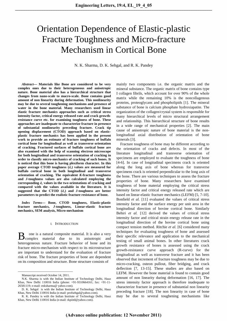
Typical P-CMOD diagrams for cortical bone are shown in Fig. 3. As per the British standard, first load maxima/pop-in point has been taken as the critical point in P-CMOD diagram [20].
In the present case no pop-in point was noticed on P-CMOD diagram and the CMOD value is found to increase steadily with load in the elastic-plastic situation. Hence, the CTOD corresponding to the maximum load point was employed for the evaluation of CTOD.
For the computation of CTOD from the CMOD value, the total CMOD corresponding to maximum load point was divided in to two parts: one is CMOD corresponding to the elastic part (ve) and other one is CMOD corresponding to the plastic part (vp) of crack opening. Fig. 4 shows the elastic and plastic parts of CMOD on the load-CMOD curve.
0.0 0.1 0.2 0.3 0.4 0.5 0.60
50
100
150
200P
max
vc
vp
ve
Loa
d (N
)
CMOD (mm)
Fig.4. Load-CMOD curve showing the elastic (ve) and plastic (vp) parts of CMOD.
The elastic (δe) and plastic (δp) parts of CTOD were
calculated using equations (1) and (2) respectively [20].
2 2(1 )
2I
e
ys
K
E
ud
s-
= (1)
where KI is the stress intensity factor corresponding to the critical load, E is the elastic modulus, σys is the yield strength and u is the Poisson’s ratio.
1( )
p
p
va
r W a
d =+
-
(2)
where vp is the plastic component of CMOD corresponding to the critical load, a is the original crack length, W is the width of the specimen and r is the rotation factor which may be taken as 0.4 as per the standard [20].
Total CTOD (δc) was calculated using equation (3) as given below;
c e pd d d= +
(3)
Stress intensity factors in case of SENB and CT tests were calculated using equation (4a) and (4b), respectively [20].
13 / 2I
PSK f
BW= and 21/ 2I
PK f
BW= (4a,b)
where 1f and 2f are the function of ( / )a Wa = and given
as:
( )( ) ( )
0.5 2
1 1.5
3 1.99 1 2.15 3.93 2.7
2 1 2 1f
a a a a a
a a
- - - +é ù é ùë ûë û=+ -
0.5 1.5 2.5 3.5 4.52 29.6 185.5 655.7 1017 639f a a a a a= - + - +
where P is the maximum load, S is the span length and B is the thickness of the specimen.
III. RESULTS
The fracture toughness value for the tibial mid diaphysis was calculated as described above for both the longitudinal and transverse orientations of fracture. Table 1 lists the elastic modulus (E), yield strength (σys) and Poisson’s ratio (u ) of buffalo tibia diaphysis determined with the help of uniaxial tensile test in both longitudinal and transverse directions. Table 2 lists the elastic part of CTOD (δe), plastic part of CTOD (δp) and the total CTOD (δc).
The equivalent fracture toughness in terms of critical stress intensity factor (Kδc) was calculated using the δc value applying the following relation [20], 2c c ysK Ed d s= (5)
and the corresponding Kδc values are also reported in Table 2.
To determine whether the specimen thickness (B) was
sufficient to meet the requirement of plane strain condition, the following equation was used [20], 25( )cB d³ (6)
TABLE 2 The elastic CTOD (δe), plastic CTOD (δp) and the total CTOD (δc), along with the equivalent fracture toughness (Kδc) of buffalo cortical tibia bone for longitudinal and transverse fracture orientations
Longitudinal orientation (n=5)
Transverse orientation (n=5)
δe (mm) 0.003±0.0005 (0.004-0.002)
0.0067±0.001 (0.008-0.006)
δp (mm) 0.036±0.0043 (0.04-0.03)
0.056±0.006 (0.06-0.05)
δc (mm)
0.039±0.0047 (0.044-0.033)
0.063±0.0068 (0.071-0.054)
Kδc (MPa.m1/2) 5.26±0.33 (5.62-4.83)
12.68±0.69 (13.47-11.74)
The results reported are the average of five values. Standard deviation are also given. The range are shown in the bracket
TABLE 1 Elastic modulus (E), yield strength (σys) and Poisson’s ratio (u ) of buffalo tibial cortical bone specimens for mid diaphysis
Longitudinal orientation
Transverse orientation
E (GPa) 19.6 11.5 σys (MPa) 65.1 31.0 u 0.38 0.35
The values listed are the average of two values.
Engineering Letters, 19:4, EL_19_4_05
(Advance online publication: 12 November 2011)
______________________________________________________________________________________
It is noticed that the maximum thickness requirement for plane strain in the present case is about 1.6 mm whereas the actual specimen thickness is 3.0 mm. Therefore, all the specimens are meeting the plane strain condition and reported δc values are the plane strain values.
After the SENB and CT testing, samples with cross-section 3 mm x 8 mm were cut from one of the bisected fractured specimens in each case to analyze the microscopic features of the fractured surfaces. These samples were cleaned in acetone and dried slowly at 60°C in a vacuum oven. Further these samples were placed in vacuum for about 4 hrs with silicate gel to remove the remaining moisture and then coated with gold for the examination under scanning electron microscope (SEM). The SEM examination was conducted on ZEISS-EV040 instrument at appropriate magnification. The SEM representative images of the fracture surfaces from the longitudinal and transversely cracked specimens are shown in Figs. 5-6 and Figs. 7-8 respectively.
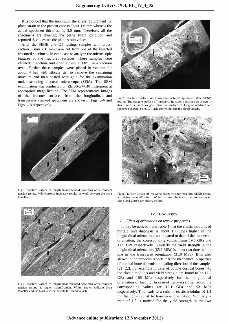
Fig.5. Fracture surface of longitudinal-fractured specimen after compact tension testing. White arrows indicate vascular network between the bone lamellae.
Fig.6. Fracture surface of longitudinal-fractured specimen after compact tension testing at higher magnification. White arrows indicate bone lamellae and the black arrows indicate the blood vessels.
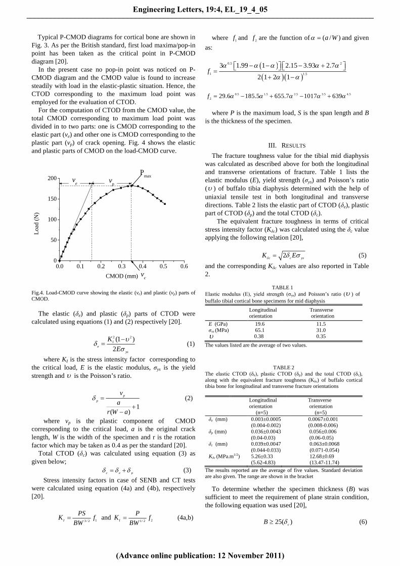
Fig.7. Fracture surface of transverse-fractured specimen after SENB testing. The fracture surface of transverse-fractured specimen as shown in this figure is much rougher than the surface of longitudinal-fractured specimen shown in Fig. 5. Black arrows indicate the blood vessels.
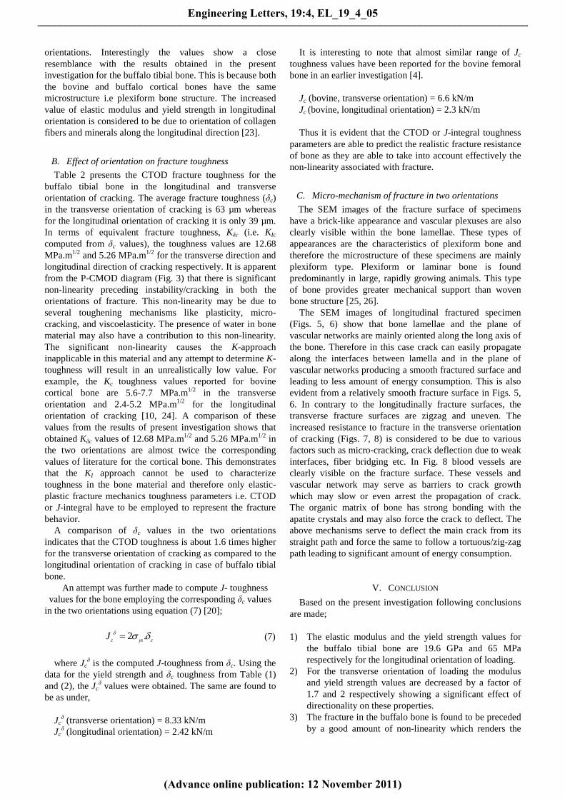
Fig.8. Fracture surface of transverse-fractured specimen after SENB testing at higher magnification. White arrows indicate the micro-cracks. The blood vessels are clearly visible.
IV. DISCUSSION
A. Effect of orientation on tensile properties
It may be noticed from Table 1 that the elastic modulus of buffalo mid diaphysis is about 1.7 times higher in the longitudinal orientation as compared to that of the transverse orientation, the corresponding values being 19.6 GPa and 11.5 GPa respectively. Similarly the yield strength in the longitudinal orientation (65.1 MPa) is about two times of the one in the transverse orientation (31.0 MPa). It is also shown in the previous reports that the mechanical properties of cortical bone depends on loading direction of the samples [21, 22]. For example in case of bovine cortical bones [4], the elastic modulus and yield strength are found to be 17.5 GPa and 166 MPa respectively for the longitudinal orientation of loading. In case of transverse orientation, the corresponding values are 12.1 GPa and 93 MPa respectively. This leads to a ratio of elastic modulus of 1.4 for the longitudinal to transverse orientation. Similarly a ratio of 1.8 is noticed for the yield strength in the two
Engineering Letters, 19:4, EL_19_4_05
(Advance online publication: 12 November 2011)
______________________________________________________________________________________
orientations. Interestingly the values show a close resemblance with the results obtained in the present investigation for the buffalo tibial bone. This is because both the bovine and buffalo cortical bones have the same microstructure i.e plexiform bone structure. The increased value of elastic modulus and yield strength in longitudinal orientation is considered to be due to orientation of collagen fibers and minerals along the longitudinal direction [23].
B. Effect of orientation on fracture toughness
Table 2 presents the CTOD fracture toughness for the buffalo tibial bone in the longitudinal and transverse orientation of cracking. The average fracture toughness (δc) in the transverse orientation of cracking is 63 µm whereas for the longitudinal orientation of cracking it is only 39 µm. In terms of equivalent fracture toughness, Kδc (i.e. KIc computed from δc values), the toughness values are 12.68 MPa.m1/2 and 5.26 MPa.m1/2 for the transverse direction and longitudinal direction of cracking respectively. It is apparent from the P-CMOD diagram (Fig. 3) that there is significant non-linearity preceding instability/cracking in both the orientations of fracture. This non-linearity may be due to several toughening mechanisms like plasticity, micro-cracking, and viscoelasticity. The presence of water in bone material may also have a contribution to this non-linearity. The significant non-linearity causes the K-approach inapplicable in this material and any attempt to determine K-toughness will result in an unrealistically low value. For example, the Kc toughness values reported for bovine cortical bone are 5.6-7.7 MPa.m1/2 in the transverse orientation and 2.4-5.2 MPa.m1/2 for the longitudinal orientation of cracking [10, 24]. A comparison of these values from the results of present investigation shows that obtained Kδc values of 12.68 MPa.m1/2 and 5.26 MPa.m1/2 in the two orientations are almost twice the corresponding values of literature for the cortical bone. This demonstrates that the KI approach cannot be used to characterize toughness in the bone material and therefore only elastic-plastic fracture mechanics toughness parameters i.e. CTOD or J-integral have to be employed to represent the fracture behavior.
A comparison of δc values in the two orientations indicates that the CTOD toughness is about 1.6 times higher for the transverse orientation of cracking as compared to the longitudinal orientation of cracking in case of buffalo tibial bone.
An attempt was further made to compute J- toughness values for the bone employing the corresponding δc values
in the two orientations using equation (7) [20];
2 .c ys cJ d s d= (7)
where Jc
δ is the computed J-toughness from δc. Using the data for the yield strength and δc toughness from Table (1) and (2), the Jc
δ values were obtained. The same are found to be as under,
Jc
δ (transverse orientation) = 8.33 kN/m Jc
δ (longitudinal orientation) = 2.42 kN/m
It is interesting to note that almost similar range of Jc toughness values have been reported for the bovine femoral bone in an earlier investigation [4].
Jc (bovine, transverse orientation) = 6.6 kN/m Jc
(bovine, longitudinal orientation) = 2.3 kN/m Thus it is evident that the CTOD or J-integral toughness
parameters are able to predict the realistic fracture resistance of bone as they are able to take into account effectively the non-linearity associated with fracture.
C. Micro-mechanism of fracture in two orientations
The SEM images of the fracture surface of specimens have a brick-like appearance and vascular plexuses are also clearly visible within the bone lamellae. These types of appearances are the characteristics of plexiform bone and therefore the microstructure of these specimens are mainly plexiform type. Plexiform or laminar bone is found predominantly in large, rapidly growing animals. This type of bone provides greater mechanical support than woven bone structure [25, 26].
The SEM images of longitudinal fractured specimen (Figs. 5, 6) show that bone lamellae and the plane of vascular networks are mainly oriented along the long axis of the bone. Therefore in this case crack can easily propagate along the interfaces between lamella and in the plane of vascular networks producing a smooth fractured surface and leading to less amount of energy consumption. This is also evident from a relatively smooth fracture surface in Figs. 5, 6. In contrary to the longitudinally fracture surfaces, the transverse fracture surfaces are zigzag and uneven. The increased resistance to fracture in the transverse orientation of cracking (Figs. 7, 8) is considered to be due to various factors such as micro-cracking, crack deflection due to weak interfaces, fiber bridging etc. In Fig. 8 blood vessels are clearly visible on the fracture surface. These vessels and vascular network may serve as barriers to crack growth which may slow or even arrest the propagation of crack. The organic matrix of bone has strong bonding with the apatite crystals and may also force the crack to deflect. The above mechanisms serve to deflect the main crack from its straight path and force the same to follow a tortuous/zig-zag path leading to significant amount of energy consumption.
V. CONCLUSION
Based on the present investigation following conclusions are made;
1) The elastic modulus and the yield strength values for
the buffalo tibial bone are 19.6 GPa and 65 MPa respectively for the longitudinal orientation of loading.
2) For the transverse orientation of loading the modulus and yield strength values are decreased by a factor of 1.7 and 2 respectively showing a significant effect of directionality on these properties.
3) The fracture in the buffalo bone is found to be preceded by a good amount of non-linearity which renders the
Engineering Letters, 19:4, EL_19_4_05
(Advance online publication: 12 November 2011)
______________________________________________________________________________________
K – approach inapplicable for evaluation of fracture toughness in the bone materials (buffalo/bovine etc.)
4) The elastic-plastic CTOD fracture toughness has been evaluated for the buffalo cortical bone in the present work and the toughness values (δc) are 39 µm and 63 µm respectively in the longitudinal and transverse orientation of cracking.
5) The equivalent K-fracture toughness (Kδc) values as obtained from the δc values are 5.26 MPa.m1/2 and 12.68 MPa.m1/2 for the longitudinal and transverse orientation of cracking which appear to be more realistic.
6) The δc values have been used to determine the equivalent J-toughness. The values of J-toughness are 8.33 kN/m for the transverse orientation and 2.42 kN/m for longitudinal orientation of cracking which shows a reasonable good agreement with the reported J-toughness in case of bovine cortical bone.
7) The orientation of vascular networks and bone lamellae are found mainly along the long axis of the bone producing a smooth fracture surface and leading to less amount of energy consumption during crack propagation along the longitudinal direction.
8) The fracture surface in case of transverse orientation of cracking is found to be much rougher and uneven as compared to the longitudinal orientation of cracking. It is considered that during crack propagation in this orientation, different mechanisms like micro-cracking, crack deflection, fiber bridging etc. serve to deflect the main crack from its straight path. All these lead to a significant amount of energy consumption during crack propagation in this orientation.
REFERENCES [1] Y. H. An and R.A. Draughn, Mechanical testing of bone and the
bone-implant interface. Florida: CRC Press, 1999, ch. 1. [2] H. D. Wager and S. Weiner, “On the relationship between the
microstructure of bone and its mechanical stiffness,” Journal of Biomechanics, vol. 25, no. 11, pp. 1311-20, Nov. 1992.
[3] N. Sasaki, N. Matsushima, T. Ikawa, H. Yamamura and A. Fukuda, “Orientation of bone minerals and its role in the anisotropic mechanical properties of bone-transverse isotropy,” Journal of Biomechanics, vol. 22, no. 2, pp. 157-164, 1989.
[4] J. Yan, J. J. Mecholsky Jr. and K. B. Clifton, “How tough is bone? Application of elastic-plastic fracture mechanics to bone,” Journal of Bone, vol. 40, no. 2, pp. 479-484, Feb. 2007.
[5] P. Lucksanasombool, W. A. J. Higgs, R. Higgs and M. V. Swain, “Effect of temperature on the fracture toughness of compact bone,” Journal of Biomaterials, vol. 22, no. 23, pp. 3127-3132, Dec. 2001.
[6] R. O. Ritchie, K. J. Koester, S. Lonova, W. Yao, N. E. Lane and J. W. Ager III, “Measurement of toughness of bone: A tutorial with special reference to small animal studies,” Journal of Bone, vol. 23, no. 5, pp. 798-815, Nov. 2008.
[7] D. Vashishth, “Rising crack-growth-resistance behavior in cortical bone: implications for toughness measurements,” Journal of Biomechanics, vol. 37, no. 6, pp. 943-946, Jun. 2004.
[8] J. Yan, K. B. Clifon, J. J. Mecholsky Jr. and L. A. Gover, “Effect of temperature on the fracture toughness of compact bone,” Journal of Biomechanics, vol. 40, no. 7, pp. 1641-1645, Jul. 2007.
[9] Y. N. Yeni, C. U. Brown and T. L. Norman, “Influence of bone composition and apparent density on fracture toughness of the human femur and tibia,” Journal of Bone, vol. 22, no. 1, pp. 79-84, Jan. 1998.
[10] Z. Feng, J. Rho, S. Han and Israel Ziv, “Orientation and loading condition dependence of fracture toughness in cortical bone,” Journal of Material Science and Engineering: C, vol. 11, no. 1, pp. 41-46, June. 2000.
[11] W. Bonfield and P. K. Dutta, “Fracture toughness of compact bone,” Journal of Biomechanics, vol. 9, no. 3, pp. 131-134, 1976.
[12] J. C. Behiri and W. Bonfield, “Fracture mechanics of bone-The effect of density, specimen thickness and crack velocity on longitudinal fracture,” Journal of Biomechanics, vol. 17, no. 1, pp. 25-34, 1984.
[13] C. L. Malik, S. M. Stover, R. B. Martin and J. C. Gibeling, “Equine cortical bone exhibits rising R-curve fracture mechanics,” Journal of Biomechanics, vol. 36, no. 2, pp. 191-198, Feb. 2003.
[14] D. Vashishth, J. C. Behiri and W. Bonfield, “Crack growth resistance in cortical bone: concept of microcrack toughening,” Journal of Biomechanics, vol. 30, no. 8, pp. 763-769, Aug. 1997.
[15] R. K. Nalla, J. J. Kruzic, J. H. Kinney and R. O. Ritchie, “Effect of aging on the toughness of human cortical bone: evaluation by R-curves,” Journal of Bone, vol. 35, no. 6, pp. 1240-1246, Dec. 2004.
[16] Q. D. Yang, B. N. Cox, R. K. Nalla and R. O. Ritchie, “Fracture length scales in human cortical bone: the necessity of non linear fracture models,” Journal of Biomaterials, vol. 27, no. 9, pp. 2095-113, Mar. 2006.
[17] Q. D. Yang, B. N. Cox, R. K. Nalla and R. O. Ritchie, “Re-evaluating the toughness of human cortical bone,” Journal of Bone, vol. 38, no. 6, pp. 878-887, Jun. 2006.
[18] A. Saxena, Nonlinear fracture mechanics. Boca Raton, Florida: CRC Press, 1998, pp. 1-13.
[19] N. K. Sharma, D. K. Sehgal and R. K. Pandey, “Effect of orientation on elastic-plastic fracture toughness of cortical bone,” Lecture Notes in Engineering and Computer Science: Proceedings of The World Congress on Engineering 2011, WCE 2011, 6-8 July, 2011, London, U. K., pp. 2298-2302
[20] Method for determination of KIc critical CTOD and critical J values of metallic materials, British Standard 7448:1, 1991.
[21] J. Y. Rho, L. Kuhn-Spearing and P. Zioupos, “Mechanical properties and the hierarchical structure of bone,” Journal of Medical Engineering and Physics, vol. 20, no. 2, pp. 92-102, Mar. 1998.
[22] R. B. Ashman, Experimental techniques in bone mechanics. Boca Raton, Florida: CRC Press, 1989, pp. 91-102.
[23] R. B. Martin and D. L. Boardman, “The effect of collagen fiber orientation, porosity, density and mineralization on bovine cortical bone bending properties,” Journal of Biomechanics, vol. 26, no. 9, pp. 1047-1054, Sep. 1993.
[24] W. Bonfield, M. D. Grynpas and R. J. Young, “Crack velocity and the fracture of bone,” Journal of Biomechanics, vol. 11, no. 10-12, pp. 473-479, 1978.
[25] X. Wang, J. D. Mabrey and C. M. Agrawal, “An interspecies comparison of bone fracture properties,” Journal of Biomedical Materials and Engg., vol. 8, no. 1, pp. 1-9, 1998.
[26] J. H. Kim, M. Niinomi, T. Akahori and H. Toda, “Fatigue properties of bovine compact bones that have different microstructure,” International Journal of Fatigue, vol. 29, pp. 1039-1050, 2007.
Engineering Letters, 19:4, EL_19_4_05
(Advance online publication: 12 November 2011)
______________________________________________________________________________________


![Effect of thermal and weld-induced residual stresses on ... · APPENDIX B. THE J-INTEGRAL AND THE CTOD AS FRACTURE PARAMETERS ... ABAQUS [12], was used for the calculations. After](https://img.pdfslide.us/doc/110x75/5abefed37f8b9ad8278ddc60/effect-of-thermal-and-weld-induced-residual-stresses-on-b-the-j-integral-and.jpg)