Embed Size (px)
Citation preview
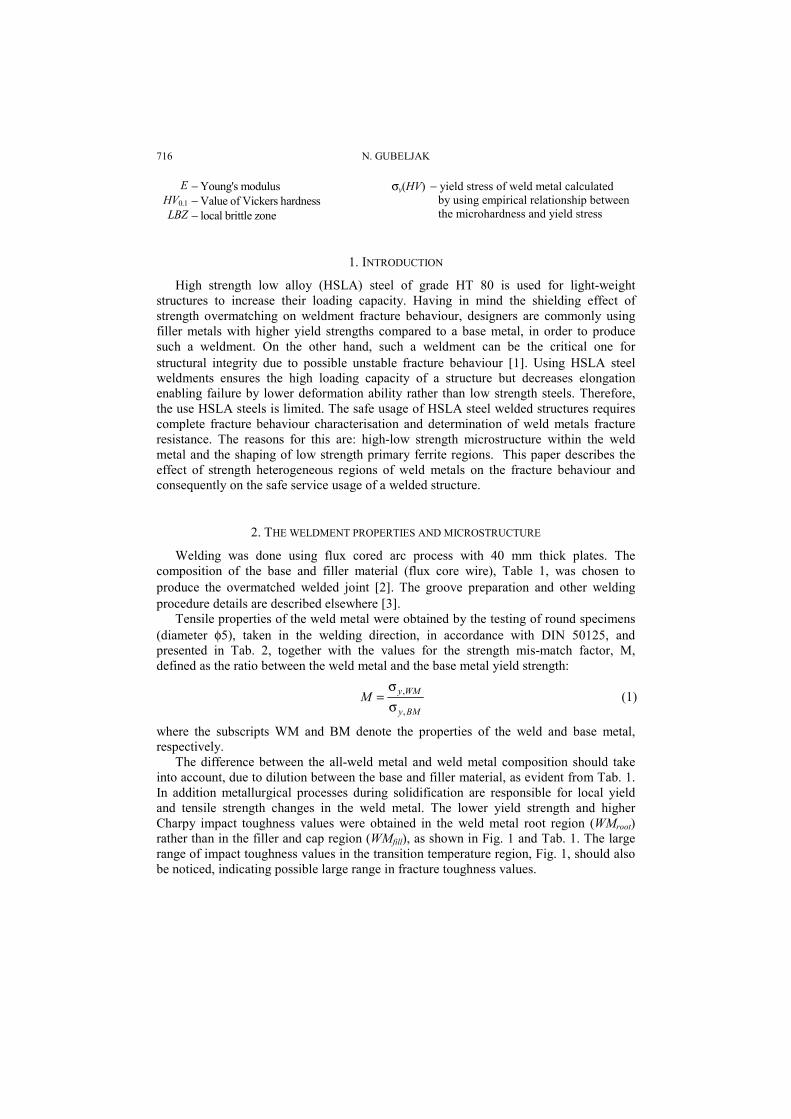
FACTA UNIVERSITATISSeries: Mechanics, Automatic Control and Robotics Vol.3, No 13, 2003, pp. 715 - 727
UNSTABLE FRACTURE BEHAVIOUR OF WELD METALAT A HIGH STRENGTH LOW ALLOY STEEL
UDC 539.388.2 669.15-194.2
Nenad Gubeljak
University of Maribor, Faculty of Mechanical EngineeringSmetanova 17, SI-2000 Maribor, Slovenia
Abstract. Local brittle zones (LBZ) cause the unstable fracture behaviour of weld metals.This threatens the safe service of welded structures and makes structural assessmentprocedures difficult. Therefore, the unstable fracture behaviour of an overmatched highstrength low alloyed steel weldment was experimentally investigated. It shows that anyinteraction between two adjacent weld metal regions with different hardness (over-to-undermatching regions) produces local brittle zones, causing local unstable fracture behaviour.The formation of a low hardness region is attributed to the multipass welding reheatingprocess between Ac1 and the self-tempering temperature. The presence of partly solidmetallic inclusions with a high content of alloying elements and pro-eutectoid ferritemicrostructure were found to be additional causes for the local unstable fracture behaviourof the weld metal. Local strength mis-match localized the yielding and strain hardening inthe undermatched region of the weld metal, contributing significantly to unstable fracturebehaviour. Thus, a significantly different scatter of experimental (fracture toughnesstesting) results can be obtained. In the cases of specimens with through-the-thickness crack,not only is the scatter significantly lower, but the toughness itself.
Key words: Fracture mechanics of welded joints, crack tip opening displacement,local brittle zones, pro-eutectoid ferrite, inclusions
NomenclatureAt − maximum tensile elongation M − mis-match factora − crack length SENB − single edge notch bend specimen
a/W − relative length of crack WDS − Wave dispersion spectrometer analysesB − thickness of specimen WM − weld metal
BM − base metal WMfill − weld metal in the filler region of weld metalCE − carbon equivalent WMroot − weld metal in the root region of weld metal
CTOD − crack tip opening displacement α − ferrite phaseCTOD − CTOD defined for a gauge length of 5mm γ − austenite phase
σyBM − average yield stress of base metalCv − impact toughness of V-notched Charpy specimen σyWM − average yield stress of weld metal
Received October 20, 2002
716 N. GUBELJAK
E − Young's modulusHV0.1 − Value of Vickers hardnessLBZ − local brittle zone
σy(HV) − yield stress of weld metal calculated by using empirical relationship between the microhardness and yield stress
1. INTRODUCTION
High strength low alloy (HSLA) steel of grade HT 80 is used for light-weightstructures to increase their loading capacity. Having in mind the shielding effect ofstrength overmatching on weldment fracture behaviour, designers are commonly usingfiller metals with higher yield strengths compared to a base metal, in order to producesuch a weldment. On the other hand, such a weldment can be the critical one forstructural integrity due to possible unstable fracture behaviour [1]. Using HSLA steelweldments ensures the high loading capacity of a structure but decreases elongationenabling failure by lower deformation ability rather than low strength steels. Therefore,the use HSLA steels is limited. The safe usage of HSLA steel welded structures requirescomplete fracture behaviour characterisation and determination of weld metals fractureresistance. The reasons for this are: high-low strength microstructure within the weldmetal and the shaping of low strength primary ferrite regions. This paper describes theeffect of strength heterogeneous regions of weld metals on the fracture behaviour andconsequently on the safe service usage of a welded structure.
2. THE WELDMENT PROPERTIES AND MICROSTRUCTURE
Welding was done using flux cored arc process with 40 mm thick plates. Thecomposition of the base and filler material (flux core wire), Table 1, was chosen toproduce the overmatched welded joint [2]. The groove preparation and other weldingprocedure details are described elsewhere [3].
Tensile properties of the weld metal were obtained by the testing of round specimens(diameter φ5), taken in the welding direction, in accordance with DIN 50125, andpresented in Tab. 2, together with the values for the strength mis-match factor, M,defined as the ratio between the weld metal and the base metal yield strength:
BMy
WMyM,
,
σσ
= (1)
where the subscripts WM and BM denote the properties of the weld and base metal,respectively.
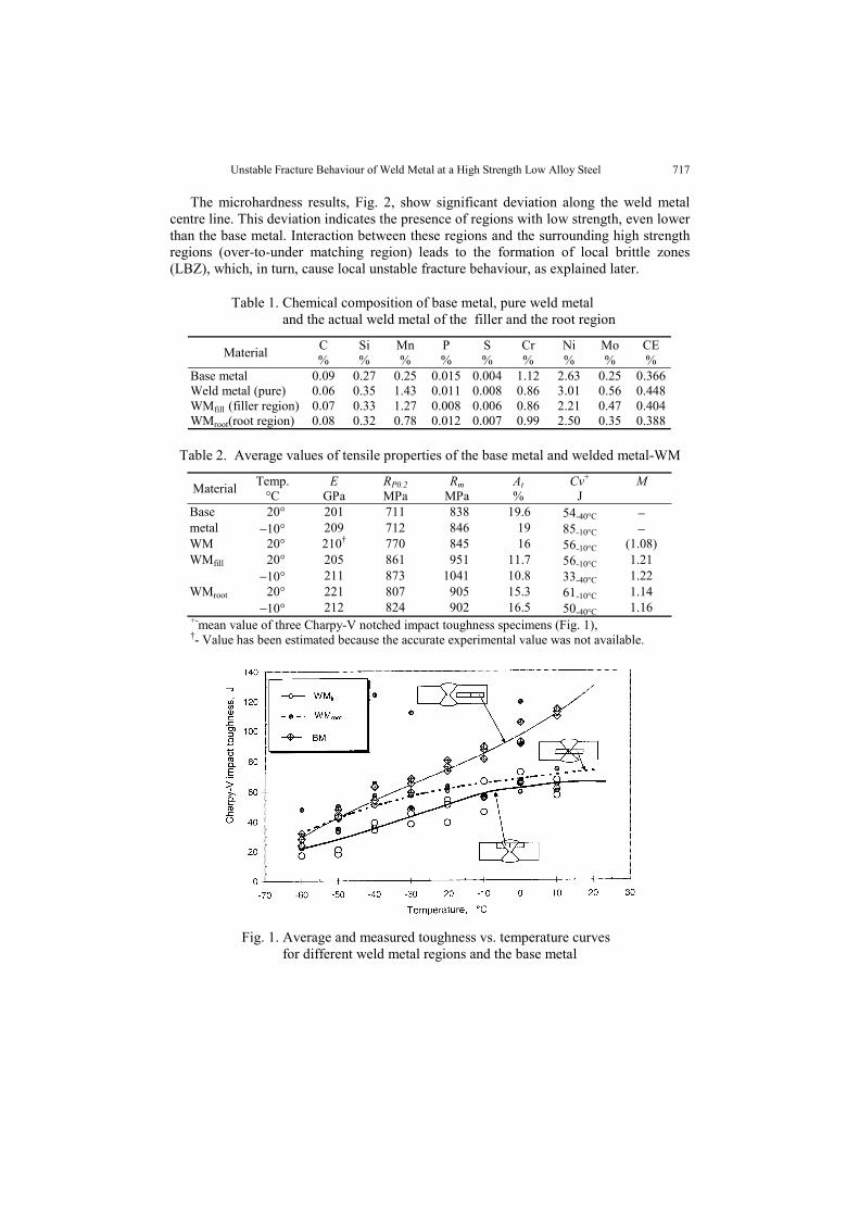
The difference between the all-weld metal and weld metal composition should takeinto account, due to dilution between the base and filler material, as evident from Tab. 1.In addition metallurgical processes during solidification are responsible for local yieldand tensile strength changes in the weld metal. The lower yield strength and higherCharpy impact toughness values were obtained in the weld metal root region (WMroot)rather than in the filler and cap region (WMfill), as shown in Fig. 1 and Tab. 1. The largerange of impact toughness values in the transition temperature region, Fig. 1, should alsobe noticed, indicating possible large range in fracture toughness values.
Unstable Fracture Behaviour of Weld Metal at a High Strength Low Alloy Steel 717
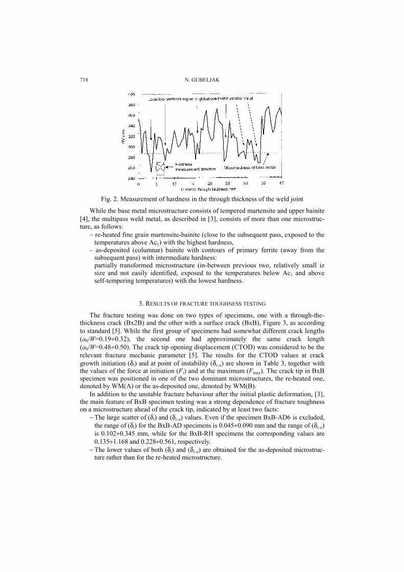
The microhardness results, Fig. 2, show significant deviation along the weld metalcentre line. This deviation indicates the presence of regions with low strength, even lowerthan the base metal. Interaction between these regions and the surrounding high strengthregions (over-to-under matching region) leads to the formation of local brittle zones(LBZ), which, in turn, cause local unstable fracture behaviour, as explained later.
Table 1. Chemical composition of base metal, pure weld metaland the actual weld metal of the filler and the root region
Material C%
Si%
Mn%
P%
S%
Cr%
Ni%
Mo%
CE%
Base metal 0.09 0.27 0.25 0.015 0.004 1.12 2.63 0.25 0.366Weld metal (pure) 0.06 0.35 1.43 0.011 0.008 0.86 3.01 0.56 0.448WMfill (filler region) 0.07 0.33 1.27 0.008 0.006 0.86 2.21 0.47 0.404WMroot(root region) 0.08 0.32 0.78 0.012 0.007 0.99 2.50 0.35 0.388
Table 2. Average values of tensile properties of the base metal and welded metal-WM
Material Temp.°C
EGPa
RP0.2MPa
RmMPa
At%
Cv+
JM
Base 20° 201 711 838 19.6 54-40°C −metal −10° 209 712 846 19 85-10°C −WM 20° 210† 770 845 16 56-10°C (1.08)WMfill 20° 205 861 951 11.7 56-10°C 1.21
−10° 211 873 1041 10.8 33-40°C 1.22WMroot 20° 221 807 905 15.3 61-10°C 1.14
−10° 212 824 902 16.5 50-40°C 1.16+-mean value of three Charpy-V notched impact toughness specimens (Fig. 1),†- Value has been estimated because the accurate experimental value was not available.
Fig. 1. Average and measured toughness vs. temperature curvesfor different weld metal regions and the base metal
718 N. GUBELJAK
Fig. 2. Measurement of hardness in the through thickness of the weld joint
While the base metal microstructure consists of tempered martensite and upper bainite[4], the multipass weld metal, as described in [3], consists of more than one microstruc-ture, as follows:
− re-heated fine grain martensite-bainite (close to the subsequent pass, exposed to thetemperatures above Ac1) with the highest hardness,
− as-deposited (columnar) bainite with contours of primary ferrite (away from thesubsequent pass) with intermediate hardness:partially transformed microstructure (in-between previous two, relatively small izsize and not easily identified, exposed to the temperatures below Ac1 and aboveself-tempering temperatures) with the lowest hardness.
3. RESULTS OF FRACTURE TOUGHNESS TESTING
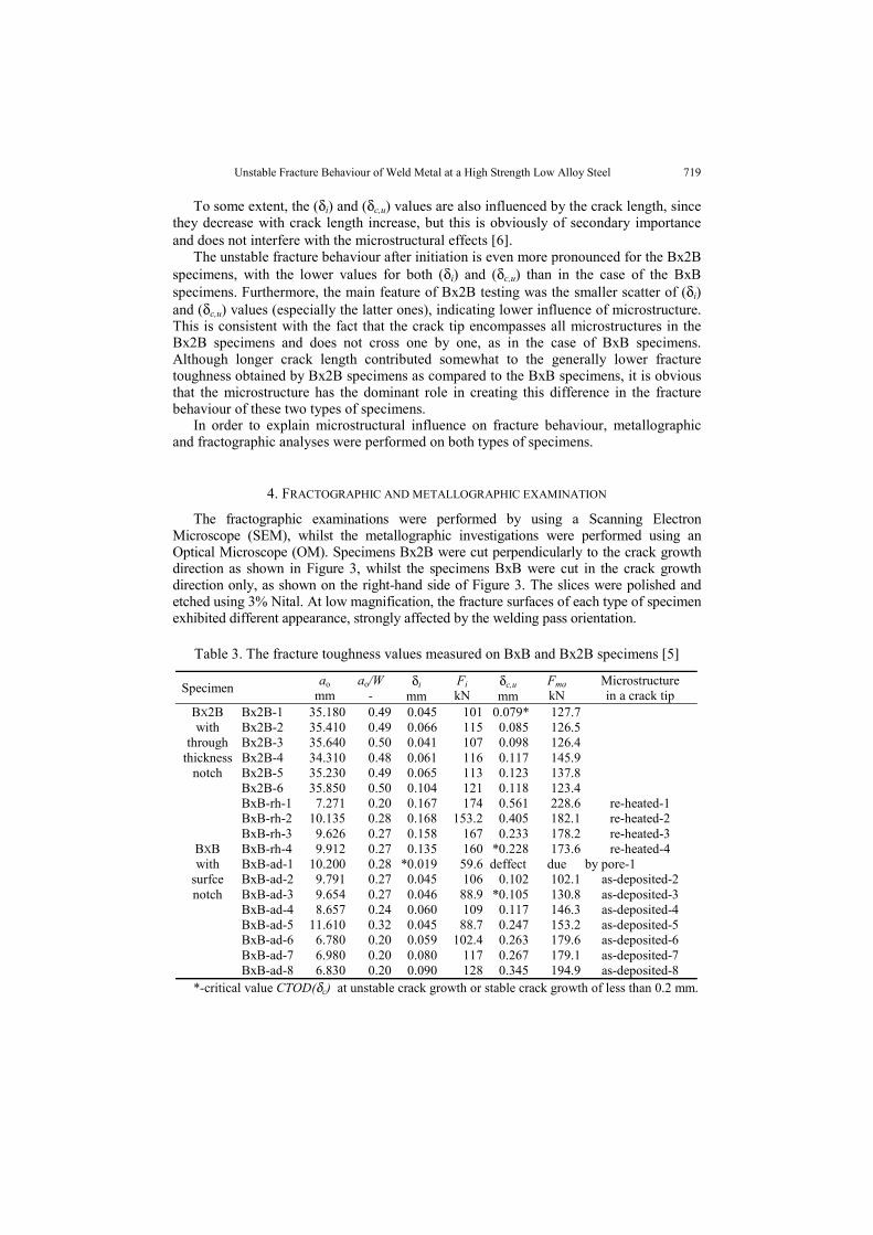
The fracture testing was done on two types of specimens, one with a through-the-thickness crack (Bx2B) and the other with a surface crack (BxB), Figure 3, as accordingto standard [5]. While the first group of specimens had somewhat different crack lengths(a0/W=0.19÷0.32), the second one had approximately the same crack length(a0/W=0.48÷0.50). The crack tip opening displacement (CTOD) was considered to be therelevant fracture mechanic parameter [5]. The results for the CTOD values at crackgrowth initiation (δi) and at point of instability (δc,u) are shown in Table 3, together withthe values of the force at initiation (Fi) and at the maximum (Fmax). The crack tip in BxBspecimen was positioned in one of the two dominant microstructures, the re-heated one,denoted by WM(A) or the as-deposited one, denoted by WM(B).
In addition to the unstable fracture behaviour after the initial plastic deformation, [3],the main feature of BxB specimen testing was a strong dependence of fracture toughnesson a microstructure ahead of the crack tip, indicated by at least two facts:
− The large scatter of (δi) and (δc,u) values. Even if the specimen BxB-AD6 is excluded,the range of (δi) for the BxB-AD specimens is 0.045÷0.090 mm and the range of (δc,u)is 0.102÷0.345 mm, while for the BxB-RH specimens the corresponding values are0.135÷1.168 and 0.228÷0.561, respectively.
− The lower values of both (δi) and (δc,u) are obtained for the as-deposited microstruc-ture rather than for the re-heated microstructure.
Unstable Fracture Behaviour of Weld Metal at a High Strength Low Alloy Steel 719
To some extent, the (δi) and (δc,u) values are also influenced by the crack length, sincethey decrease with crack length increase, but this is obviously of secondary importanceand does not interfere with the microstructural effects [6].
The unstable fracture behaviour after initiation is even more pronounced for the Bx2Bspecimens, with the lower values for both (δi) and (δc,u) than in the case of the BxBspecimens. Furthermore, the main feature of Bx2B testing was the smaller scatter of (δi)and (δc,u) values (especially the latter ones), indicating lower influence of microstructure.This is consistent with the fact that the crack tip encompasses all microstructures in theBx2B specimens and does not cross one by one, as in the case of BxB specimens.Although longer crack length contributed somewhat to the generally lower fracturetoughness obtained by Bx2B specimens as compared to the BxB specimens, it is obviousthat the microstructure has the dominant role in creating this difference in the fracturebehaviour of these two types of specimens.
In order to explain microstructural influence on fracture behaviour, metallographicand fractographic analyses were performed on both types of specimens.
4. FRACTOGRAPHIC AND METALLOGRAPHIC EXAMINATION
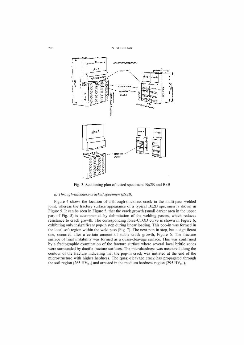
The fractographic examinations were performed by using a Scanning ElectronMicroscope (SEM), whilst the metallographic investigations were performed using anOptical Microscope (OM). Specimens Bx2B were cut perpendicularly to the crack growthdirection as shown in Figure 3, whilst the specimens BxB were cut in the crack growthdirection only, as shown on the right-hand side of Figure 3. The slices were polished andetched using 3% Nital. At low magnification, the fracture surfaces of each type of specimenexhibited different appearance, strongly affected by the welding pass orientation.
Table 3. The fracture toughness values measured on BxB and Bx2B specimens [5]
Specimen aomm
ao/W-
δimm
FikN
δc,umm
FmakN
Microstructurein a crack tip
BX2B Bx2B-1 35.180 0.49 0.045 101 0.079* 127.7with Bx2B-2 35.410 0.49 0.066 115 0.085 126.5
through Bx2B-3 35.640 0.50 0.041 107 0.098 126.4thickness Bx2B-4 34.310 0.48 0.061 116 0.117 145.9
notch Bx2B-5 35.230 0.49 0.065 113 0.123 137.8Bx2B-6 35.850 0.50 0.104 121 0.118 123.4BxB-rh-1 7.271 0.20 0.167 174 0.561 228.6 re-heated-1BxB-rh-2 10.135 0.28 0.168 153.2 0.405 182.1 re-heated-2BxB-rh-3 9.626 0.27 0.158 167 0.233 178.2 re-heated-3
BXB BxB-rh-4 9.912 0.27 0.135 160 *0.228 173.6 re-heated-4with BxB-ad-1 10.200 0.28 *0.019 59.6 deffect due by pore-1
surfce BxB-ad-2 9.791 0.27 0.045 106 0.102 102.1 as-deposited-2notch BxB-ad-3 9.654 0.27 0.046 88.9 *0.105 130.8 as-deposited-3
BxB-ad-4 8.657 0.24 0.060 109 0.117 146.3 as-deposited-4BxB-ad-5 11.610 0.32 0.045 88.7 0.247 153.2 as-deposited-5BxB-ad-6 6.780 0.20 0.059 102.4 0.263 179.6 as-deposited-6BxB-ad-7 6.980 0.20 0.080 117 0.267 179.1 as-deposited-7BxB-ad-8 6.830 0.20 0.090 128 0.345 194.9 as-deposited-8
*-critical value CTOD(δc) at unstable crack growth or stable crack growth of less than 0.2 mm.
720 N. GUBELJAK
Fig. 3. Sectioning plan of tested specimens Bx2B and BxB
a) Through-thickness-cracked specimen (Bx2B)
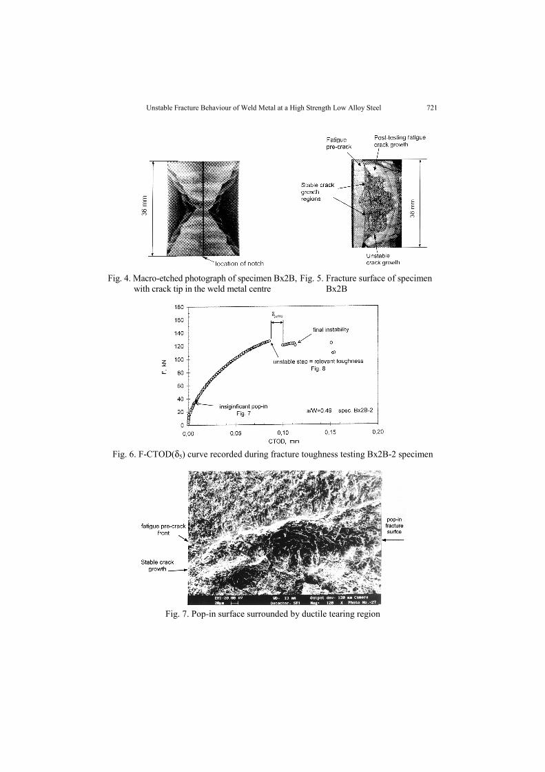
Figure 4 shows the location of a through-thickness crack in the multi-pass weldedjoint, whereas the fracture surface appearance of a typical Bx2B specimen is shown inFigure 5. It can be seen in Figure 5, that the crack growth (small darker area in the upperpart of Fig. 5) is accompanied by delimitation of the welding passes, which reducesresistance to crack growth. The corresponding force-CTOD curve is shown in Figure 6,exhibiting only insignificant pop-in step during linear loading. This pop-in was formed inthe local soft region within the weld pass (Fig. 7). The next pop-in step, but a significantone, occurred after a certain amount of stable crack growth, Figure 6. The fracturesurface of final instability was formed as a quasi-cleavage surface. This was confirmedby a fractographic examination of the fracture surface where several local brittle zoneswere surrounded by ductile fracture surfaces. The microhardness was measured along thecontour of the fracture indicating that the pop-in crack was initiated at the end of themicrostructure with higher hardness. The quasi-cleavage crack has propagated throughthe soft region (265 HV0.1) and arrested in the medium hardness region (295 HV0.1).
Unstable Fracture Behaviour of Weld Metal at a High Strength Low Alloy Steel 721
Fig. 4. Macro-etched photograph of specimen Bx2B,with crack tip in the weld metal centre
Fig. 5. Fracture surface of specimenBx2B
Fig. 6. F-CTOD(δ5) curve recorded during fracture toughness testing Bx2B-2 specimen
Fig. 7. Pop-in surface surrounded by ductile tearing region
722 N. GUBELJAK
b) Shallow-cracked specimen (BxB)
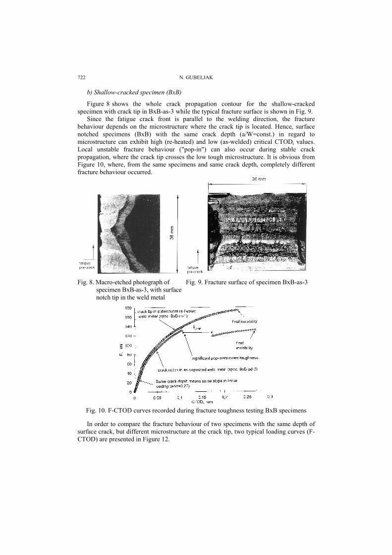
Figure 8 shows the whole crack propagation contour for the shallow-crackedspecimen with crack tip in BxB-as-3 while the typical fracture surface is shown in Fig. 9.
Since the fatigue crack front is parallel to the welding direction, the fracturebehaviour depends on the microstructure where the crack tip is located. Hence, surfacenotched specimens (BxB) with the same crack depth (a/W=const.) in regard tomicrostructure can exhibit high (re-heated) and low (as-welded) critical CTODi values.Local unstable fracture behaviour ("pop-in") can also occur during stable crackpropagation, where the crack tip crosses the low tough microstructure. It is obvious fromFigure 10, where, from the same specimens and same crack depth, completely differentfracture behaviour occurred.
Fig. 8. Macro-etched photograph ofspecimen BxB-as-3, with surfacenotch tip in the weld metal
Fig. 9. Fracture surface of specimen BxB-as-3
Fig. 10. F-CTOD curves recorded during fracture toughness testing BxB specimens
In order to compare the fracture behaviour of two specimens with the same depth ofsurface crack, but different microstructure at the crack tip, two typical loading curves (F-CTOD) are presented in Figure 12.
Unstable Fracture Behaviour of Weld Metal at a High Strength Low Alloy Steel 723
The loading curve for the specimen (BxB-10) with the crack-tip in as-welded columnarmicrostructure shows pop-in event. The significant pop-in step occurred below the linearloading when the crack tip was located in the as-deposited region. After the pop-in step anda certain amount of stable crack propagation and CTOD, final instability occurred.
The specimen (BxB-1) with the crack tip in the re-heated microstructure, exhibitedstable crack propagation without pop-ins, Figure 12. Crack tip located in fine martensitewith contours of primary ferrite (PF). The final instability was initiated by several originsalong the front of the ductile crack growth, producing a quasi-cleavage fracture.
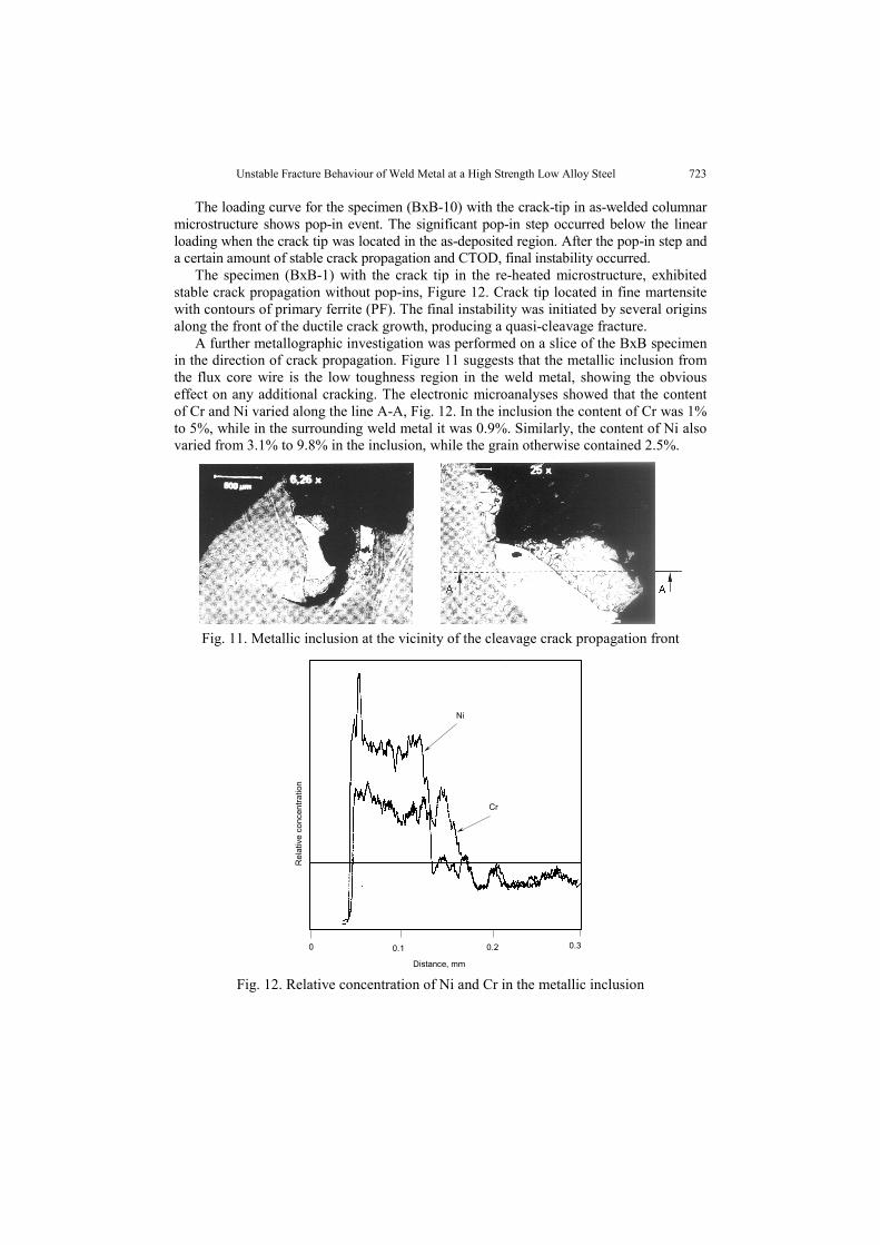
A further metallographic investigation was performed on a slice of the BxB specimenin the direction of crack propagation. Figure 11 suggests that the metallic inclusion fromthe flux core wire is the low toughness region in the weld metal, showing the obviouseffect on any additional cracking. The electronic microanalyses showed that the contentof Cr and Ni varied along the line A-A, Fig. 12. In the inclusion the content of Cr was 1%to 5%, while in the surrounding weld metal it was 0.9%. Similarly, the content of Ni alsovaried from 3.1% to 9.8% in the inclusion, while the grain otherwise contained 2.5%.
Fig. 11. Metallic inclusion at the vicinity of the cleavage crack propagation front
Cr
Ni
Distance, mm
0 0.1 0.2 0.3
Rel
ativ
e co
ncen
tratio
n
Fig. 12. Relative concentration of Ni and Cr in the metallic inclusion
724 N. GUBELJAK
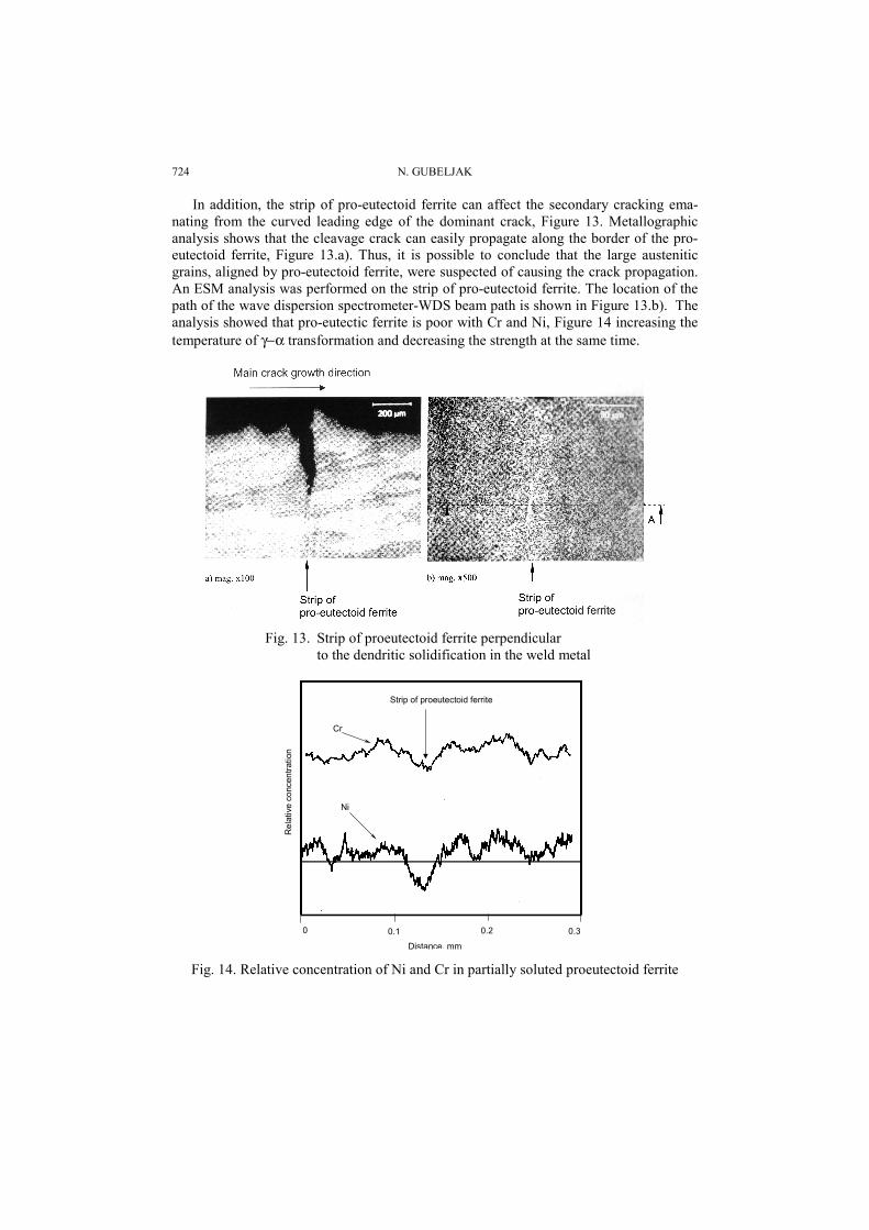
In addition, the strip of pro-eutectoid ferrite can affect the secondary cracking ema-nating from the curved leading edge of the dominant crack, Figure 13. Metallographicanalysis shows that the cleavage crack can easily propagate along the border of the pro-eutectoid ferrite, Figure 13.a). Thus, it is possible to conclude that the large austeniticgrains, aligned by pro-eutectoid ferrite, were suspected of causing the crack propagation.An ESM analysis was performed on the strip of pro-eutectoid ferrite. The location of thepath of the wave dispersion spectrometer-WDS beam path is shown in Figure 13.b). Theanalysis showed that pro-eutectic ferrite is poor with Cr and Ni, Figure 14 increasing thetemperature of γ−α transformation and decreasing the strength at the same time.
Fig. 13. Strip of proeutectoid ferrite perpendicularto the dendritic solidification in the weld metal
Strip of proeutectoid ferrite
Cr
Ni
Distance, mm
0 0.1 0.2 0.3
Rel
ativ
e co
ncen
tratio
n
Fig. 14. Relative concentration of Ni and Cr in partially soluted proeutectoid ferrite
Unstable Fracture Behaviour of Weld Metal at a High Strength Low Alloy Steel 725
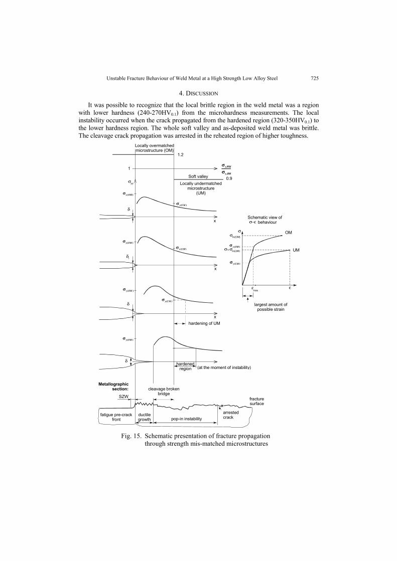
4. DISCUSSION
It was possible to recognize that the local brittle region in the weld metal was a regionwith lower hardness (240-270HV0.1) from the microhardness measurements. The localinstability occurred when the crack propagated from the hardened region (320-350HV0.1) tothe lower hardness region. The whole soft valley and as-deposited weld metal was brittle.The cleavage crack propagation was arrested in the reheated region of higher toughness.
BMy
WMy
,
,
σσ
)(OMyσ
)(UMyσ
)(UMyσ
)(UMyσ
)(OMyσ
)(OMyσ
)(OMyσ
)(OMyσ
)(UMyσ
OM
UM
ε
σ
σ−ε
σm(OM)
maxε
largest amount ofpossible strain
Schematic view of behaviour
σ σm(UM)
δ
σyy Locally undermatchedmicrostructure
(UM)
0.9
Locally overmatchedmicrostructure (OM)
1.2
1
x
fatigue pre-crackfront
SZW
ductilegrowth pop-in instability
arrestedcrack
cleavage brokenbridge
hardenedregion (at the moment of instability)
xfracturesurface
δ
δ
δ
i
hardening of UM
x
x
Metallographicsection:
Soft valleyBMy
WMy
,
,
σ
)(OMy
)(UMy
)(UMy
)(UMy
)(OMy
)(OMy
)(OMy
)(OMy
)(UMy
Fig. 15. Schematic presentation of fracture propagationthrough strength mis-matched microstructures
726 N. GUBELJAK
Figure 15 schematically illustrates fracture behaviour during crack propagation fromthe overmatched to the undermatched microstructures'. The crack tip was blunted in theovermatched region, creating a corresponding stress field. During the stable crack propa-gation the stress peak decreased slightly and shifted with the stable crack tip towards theundermatched microstructure. The overmatching stress field in the vicinity of the under-matched weld metal caused hardening of the undermatched microstructure. This hap-pened prior to the crack tip coming into contact with the undermatched microstructure.The initiation of the cleavage fracture was caused by a critical level of hardening in theundermatched weld metal. The cleavage bridge was partly formed in the overmatchedweld metal at the point of instability.
The described fracture behaviour always occurred when the stable crack propagatedto the undermatched weld metal or the microstructure with lower toughness. In this caseit is impossible to prevent pop-in step. As shown, other brittle microstructures involvemetallic inclusions and pro-eutectoid ferrite. The effect of metallic inclusion dependsstrongly on their size, shape and hardness. In the case of inclusions like the one shown inFigure 13, the dominating effect is due to increased hardness and interaction with thesurrounding weld metal, which then acts as a softer material according to the mechanismdescribed in Figure 14. Nevertheless, in this case, the effect is local and not of the sameimportance as when different microstructures interact. On the other hand, the effect ofpro-eutectoid ferrite has not involved the mechanism described in Figure 25, but ratherthe secondary cracking along the characteristic direction of microstructure, Figure 13.a)and b). The fact that pro-eutectoid ferrite has lower strength due to decreased content ofCr and Ni, does not produce the hardening effect because the primary stress field isuninvolved, i.e. this microstructure is not ahead of the crack tip.
5. CONCLUSIONS
This analysis of the unstable fracture behaviour of an overmatched weld metal hasshown that a high strength material is extremely sensitive to the presence of strength mis-matched local regions.
The overmatched weld metal exhibits an unstable crack propagation, whilst the basemetal is ductile. Unstable crack propagation of a weld metal is affected by:
a) local strength mis-matched microstructures,b) direction of crack propagation
The local strength mis-match within a weld metal is affected by the presence of:a) local soft region tempered between Ac1 and self-tempering temperature.b) partly solid metallic inclusions with higher contents of alloying elementsc) pro-eutectoid ferrite
Local strength mis-match localized the yielding and strain hardening in the under-matched region of the weld metal, contributing significantly to unstable fracture behav-iour.
The direction of crack propagation relating to the sequence of welding passes alsoaffects fracture behaviour. In the case of the shallow-cracked specimens, fracturebehaviour is affected by the position of the crack tip. If the crack tip is in the re-heatedmicrostructure then ductile crack propagation can occur with or without insignificant
Unstable Fracture Behaviour of Weld Metal at a High Strength Low Alloy Steel 727
pop-in. If the crack tip is located in the as-deposited microstructure the pop-in unstablestep or unstable fracture behaviour is commonly exhibited. Thus, a significantly differentrange of experimental results can be obtained. In the cases of specimens with through-the-thickness cracks, the range is significantly lower, but also the toughness itself. Thearrest of the unstable crack growth is not only the consequence of a load drop, but thepresence of a microstructure where the crack tip is arrested. Structural integrity ispossible to ensure not only by an appropriate structure assessment integrity procedure,but also by considering elements which threaten the sage service of the overmatchedwelded joint. Consumables for high strength overmatching welded joints (yielding above700 MPa) are subjected to local brittle zones. Therefore, such a weld joint requiresmetallographic analysis as explanation of the experimentally obtained fracture behaviour.
REFERENCES
1. Gubeljak N.: "Fracture behaviour of specimens with surface notch tip in the heat affected zone (HAZ) ofstrength mis-matched welded joints. Int. j. fract., Dec. 1999, vol. 100, issue 2, pp. 155-167.
2. Defourny J.: "Guide to Weldability and Metallurgy of Welding of Steels Processed by ThermomechanicalRolling or by Accelerated Cooling", IIW Doc. IX-1649-91 and IXA-32-91
3. Vojvodic-Tuma, J.: "Determination of Lower Bound Fracture Toughness of the Overmatched WeldMetal of High Strength Low Alloy Steel", submitted to journal Engineering Fracture Mechanics, 2002.
4. "Compendium of Weld Metal Microstructures and Properties (Submerged-arc Welds in Ferritic Steel)",Prepared for Commission IX of the International Institute of Welding by Sub-Commission IXJ, TheWelding Institute Abington Hall, Cambridge UK 1985#
5. BS 7448: Part 2: 1997: Fracture mechanics toughness test, Part 2. Method for determination of KIc, criticalCTOD and critical J values of welds in metallic materials, British standards institution, London, 1997
6. Gubeljak N., Legat, J., Koçak, M.:"Effect of Fracture Path on Toughness of Weld Metal", to submittedin International Journal of Fracture, 2002
NESTABILNO LOMNO PONAŠANJE METALA ŠAVAKOD NISKOLEGIRANOG ČELIKA POVIŠENE ČVRSTOĆE
Nenad Gubeljak
Lokalno krhka područja (LKP) uzrokuju nestabilno lomno ponašanje metala šava. LKP timeugrožavaju sigurnu eksploataciju zavarene konstrukcije, a procena integriteta konstrukcije postajezahtevnija. Zbog toga je potrebno detaljnije istražiti uzrok nestabilnom lomu metala šava kodniskolegiranog čelika povišene čvrstoće. Istraživanja su pokazala, da interakcija izmedju dvemikrostrukture metala šava s različitim ojačavanjem može prouzrokovati nastanak LKP, koje uzrokujenestabilno lomno ponašanje. Oblikovanje područja niske čvrstoće i tvrdoće u metalu šava s višeprolaza je posledica ponovnog segrevanja na temperature izmedju Ac1 i temperature samopopuštanja.Prisutnost delimično stvrdjenih metalnih uključaka s visokim postotkom legirnih elemenata i pro-eutektičkog ferita može biti dodatan uzrok za lokalno nestabilno lomno ponašanje metala šava.Spomenuta područja karakteriše bitno niža granica tečenja s različitim deformacijskim ojačavanjem umetalu šava globalno visoke čvrstoće, što može dodatno prouzrokovati nestabilno lomno ponašanjemetala šava. Istraživanja su pokazala da je to jedan od ključnih elemenata koji prouzrokuju rasipanjeeksperimentalnih rezultata kao što je kritična vrednost parametra lomne žilavosti, kad se prslina širiiz jedne zavarenog prolaza prema drugom. U slučaju lomnomehaničkih ispitivanja s prsilnom krozviše zavarenih prolaza istovremeno (prislina prolazi kroz debljinu celog spoja) je rasipanje rezultatauz opšte nisku žilavost mnogo manje.