Embed Size (px)
Citation preview
8/2/2019 An Efficient Viterbi Decoder
http://slidepdf.com/reader/full/an-efficient-viterbi-decoder 1/16
International Journal of Advanced Information Technology (IJAIT) Vol. 2, No.1, February 2012
DOI : 10.5121/ijcsea.2012.2110 101
A NEFFICIENT V ITERBIDECODER
K. S. Arunlal1
and Dr. S. A. Hariprasad2
1Research Scholar, R. V. Center for Cognitive Technologies, Bangalore, India
2Director, R. V. Center for Cognitive Technologies, Bangalore, Karnataka, India
ABSTRACT
Convolutional encoding with Viterbi decoding is a good forward error correction technique suitable for
channels affected by noise degradation. Fangled Viterbi decoders are variants of Viterbi decoder (VD)which decodes quicker and takes less memory with no error detection capability. Modified fangled takes it
a step further by gaining one bit error correction and detection capability at the cost of doubling the
computational complexity and processing time. A new efficient fangled Viterbi algorithm is proposed in this
paper with less complexity and processing time along with 2 bit error correction capabilities. For 1 bit
error correction for 14 bit input data, when compared with Modified fangled Viterbi decoder,
computational complexity has come down by 36-43% and processing delay was halved. For a 2 bit error
correction, when compared with Modified fangled decoder computational complexity decreased by 22-
36%.
K EYWORDS
Constraint length, Path metric, Trellis diagram, Code rate, Euclidean distance, hamming distance,
interleavers.
1. INTRODUCTION
Viterbi decoding was developed by Andrew J. Viterbi, is an Italian-American electrical engineer
and businessman who co-founded Qualcomm Inc. His seminar paper titled "Error Bounds forConvolutional Codes and an Asymptotically Optimum Decoding Algorithm", published in IEEE
Transactions on Information Theory, in April, 1967 [1]. Since then, other researchers haveexpanded on his work by finding good convolutional codes, exploring the performance limits of the technique, and varying decoder design parameters to optimize the implementation of the
technique in hardware and software. Design and Implementation of Viterbi Decoder with FPGAs
by M. Kivoja and et.al [6] have analyzed suitability of FPGA device architectures for
implementing complex algorithms. They choose Viterbi algorithm as a deeper case study.
Different architectural strategies for implementations are discussed and analyzed with the specialemphasis on practical FPGA implementations. Speed performance, easy routability andminimization of inter-chip communication are used as design criteria. Viterbi decoder, constraint
length seven, was designed and simulated with VHDL in Synopsys and Mentor tool environments
and further implemented on four Xilinx 4028EX devices using trace-back based architecture.Also partitioning aspects of the decoding algorithm are presented and analyzed. A Fast
Maximum-Likelihood Decoder for Convolutional Codes by Jon Feldman et.al [9], describes the
Lazy Viterbi decoder which is a maximum-likelihood decoder for block and stream convolutional
8/2/2019 An Efficient Viterbi Decoder
http://slidepdf.com/reader/full/an-efficient-viterbi-decoder 2/16
International Journal of Computer Science, Engineering and Applications (IJCSEA) Vol.2, No.1, February 2012
102
codes. For many codes of practical interest, under reasonable noise conditions, the lazy decoder is
much faster than the original Viterbi decoder. A novel design and implementation of an onlinereconfigurable Viterbi decoder is proposed based on an area-efficient ACS architecture [12], in
which the constraint length and trace back depth can be dynamically reconfigured. TheArchitecture can provide various throughput and energy trade-offs. Considering the
throughput/energy performance metric, experimental results [15] show that design achievesimprovements up to 26.1% compared with the previous designs. A novel systolic array-based
architecture [17] with time multiplexing and arithmetic pipelining for implementing the proposed
algorithm is used. The proposed algorithm can reduce by up to 70% the average number of ACScomputations over that by using the non-adaptive Viterbi algorithm, without degradation in theerror performance. Further, the total power consumption in the implementation of the proposed
algorithm can be reduced by up to 43% compared to that in the implementation of the non-adaptive Viterbi algorithm, with a negligible increase in the hardware. FPGA implementation of
Viterbi decoder by Hema S and et.al [21] describes the field-programmable gate array
implementation of Viterbi Decoder with a constraint length of 11 and a code rate of 1/3. It showsthat the larger the constraint length better will be the coding. In this paper an Efficient fangled
viterbi decoder is discussed which will decrease computational complexity and also enhanceserror correction capabilities. This algorithm is less complex and takes less memory when
compared to the existing Viterbi decoders but more than Fangled Viterbi Decoder with anadvantage of two bit error correction capability.
2. VITERBI DECODER
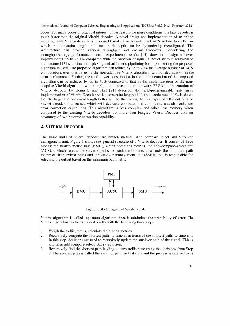
The basic units of viterbi decoder are branch metrics, Add compare select and Survivor
management unit. Figure 1 shows the general structure of a Viterbi decoder. It consist of threeblocks: the branch metric unit (BMU), which computes metrics, the add–compare–select unit
(ACSU), which selects the survivor paths for each trellis state, also finds the minimum pathmetric of the survivor paths and the survivor management unit (SMU), that is responsible for
selecting the output based on the minimum path metric.
Figure 1. Block diagram of Viterbi decoder
Viterbi algorithm is called optimum algorithm since it minimizes the probability of error. TheViterbi algorithm can be explained briefly with the following three steps.
1. Weigh the trellis; that is, calculate the branch metrics.
2. Recursively compute the shortest paths to time n, in terms of the shortest paths to time n-1.In this step, decisions are used to recursively update the survivor path of the signal. This is
known as add-compare-select (ACS) recursion.3. Recursively find the shortest path leading to each trellis state using the decisions from Step
2. The shortest path is called the survivor path for that state and the process is referred to as
Input Output
PMU
ACSU SMUBMU
8/2/2019 An Efficient Viterbi Decoder
http://slidepdf.com/reader/full/an-efficient-viterbi-decoder 3/16
International Journal of Computer Science, Engineering and Applications (IJCSEA) Vol.2, No.1, February 2012
103
survivor path decode. Finally, if all survivor paths are traced back in time, they merge into a
unique path, which is the most likely signal path.
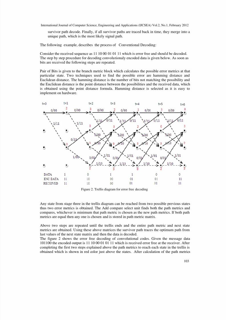
The following example, describes the process of Conventional Decoding:
Consider the received sequence as 11 10 00 01 01 11 which is error free and should be decoded.The step by step procedure for decoding convolutionaly encoded data is given below. As soon as
bits are received the following steps are repeated.
Pair of Bits is given to the branch metric block which calculates the possible error metrics at thatparticular state. Two techniques used to find the possible error are hamming distance and
Euclidean distance. The hamming distance is the number of bits not matching the possibility andthe Euclidean distance is the point distance between the possibilities and the received data, which
is obtained using the point distance formula. Hamming distance is selected as it is easy to
implement on hardware.
Figure 2. Trellis diagram for error free decoding
Any state from stage three in the trellis diagram can be reached from two possible previous states
thus two error metrics is obtained. The Add compare select unit finds both the path metrics andcompares, whichever is minimum that path metric is chosen as the new path metrics. If both pathmetrics are equal then any one is chosen and is stored in path metric matrix.
Above two steps are repeated until the trellis ends and the entire path metric and next statemetrics are obtained. Using these above matrices the survivor path traces the optimum path fromlast values of the next state matrix and then the data is decoded.
The figure 2 shows the error free decoding of convolutional codes. Given the message data101100 the encoded output is 11 10 00 01 01 11 which is received error free at the receiver. After
completing the first two steps explained above the path metrics to reach each state in the trellis is
obtained which is shown in red color just above the states. After calculation of the path metrics

8/2/2019 An Efficient Viterbi Decoder
http://slidepdf.com/reader/full/an-efficient-viterbi-decoder 4/16
International Journal of Computer Science, Engineering and Applications (IJCSEA) Vol.2, No.1, February 2012
104
the survivor unit traces back the optimum path which will always start from state zero as shown
in figure 2.
3. FANGLED VITERBI DECODER
Conventional Viterbi decoders have redundancies involved in path calculation, extra path andbranch metric computation, added processing delay and higher memory requirement. These
parameters closely depend on the constraint length of decoder i.e. K, higher the constraint lengthmore robust is the code but every parameter is increased like number of computations, processing
delay, memory requirement will increase exponentially, so will the device utilization and arearequired.
In fangled viterbi decoder , the redundancies are reduced, hence it take less processing time alongwith less memory but without any error correction capability.
The working principle of Fangled decoding technique can be explained with the following
example:
For Fangled Decoding technique, considering the transmitted data as 11 10 00 01 01 11 but due to
channel impairments the received data be 10 10 00 01 01 11 i.e. the received data is not as sameas the transmitted one and the error is in second bit.
Received Data 11 10
Selected state 0 2 1
Decoded data 1 0
Figure 3. Error free fangled second step.
The trellis decoding for the first two bits are shown in figure 3. Initially the first two bits are
given to the branch metrics unit, which replicates the encoder and compares with the possiblenext state, at beginning it can either take 002 or 102 states. Calculating the branch metrics for the
both the possible states is 1 as shown in figure 3 thus the ACSU has to choose between the two
possible states but both are having same branch metrics thus a conflicting situation will arise atthis stage.
ACSU randomly selects any of the state among the possible thus this conflicting situation is not
clearly solved in the fangled scheme resulting in erroneous decoding of the data.
The fangled scheme works well for error free data but the disadvantages of this scheme is whendata received with error at particular stage then conflicting situation will arise and the ACSU has
8/2/2019 An Efficient Viterbi Decoder
http://slidepdf.com/reader/full/an-efficient-viterbi-decoder 5/16
International Journal of Computer Science, Engineering and Applications (IJCSEA) Vol.2, No.1, February 2012
105
to decide which path to choose as both the error metrics will be equal if one bit is received in
error. Thus to avoid this, ACSU randomly chooses a path metrics which leads to incorrectdecoding of bits. In [15], interleaver is been combined with the fangled scheme to get good
results but this does not solve the above problem. As interleavers does the function of shufflingthe bits in the frames which converts burst error to random error but still error is present. Thus
decoding of erroneous data is the main disadvantage of the fangled scheme which can beovercome by slight modification of the algorithm which is explained in next section called
Modified fangled scheme.
3.1 RESULT OF CONVOLUTION ENCODING AND FANGLED DECODING
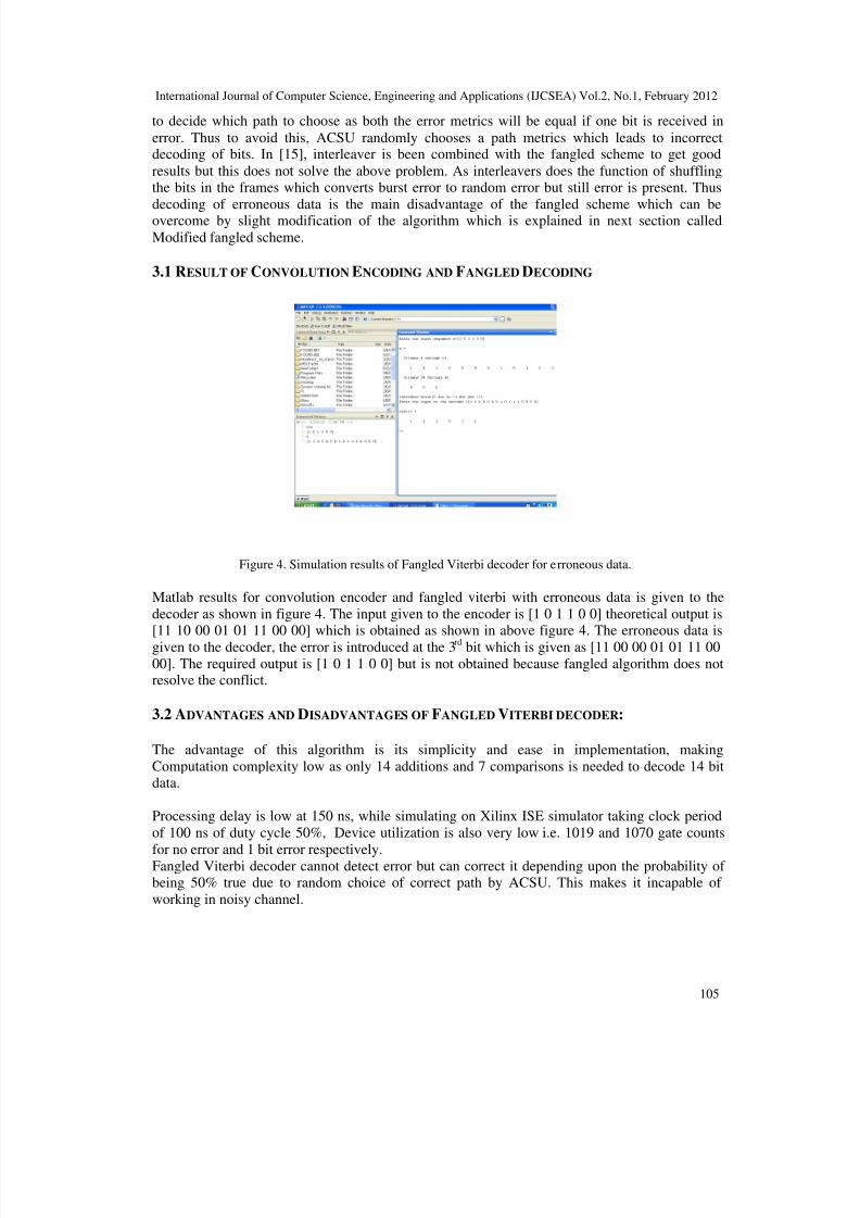
Figure 4. Simulation results of Fangled Viterbi decoder for erroneous data.
Matlab results for convolution encoder and fangled viterbi with erroneous data is given to the
decoder as shown in figure 4. The input given to the encoder is [1 0 1 1 0 0] theoretical output is[11 10 00 01 01 11 00 00] which is obtained as shown in above figure 4. The erroneous data is
given to the decoder, the error is introduced at the 3 rd bit which is given as [11 00 00 01 01 11 00
00]. The required output is [1 0 1 1 0 0] but is not obtained because fangled algorithm does notresolve the conflict.
3.2 ADVANTAGES AND DISADVANTAGES OF FANGLED VITERBI DECODER:
The advantage of this algorithm is its simplicity and ease in implementation, making
Computation complexity low as only 14 additions and 7 comparisons is needed to decode 14 bitdata.
Processing delay is low at 150 ns, while simulating on Xilinx ISE simulator taking clock period
of 100 ns of duty cycle 50%, Device utilization is also very low i.e. 1019 and 1070 gate counts
for no error and 1 bit error respectively.Fangled Viterbi decoder cannot detect error but can correct it depending upon the probability of being 50% true due to random choice of correct path by ACSU. This makes it incapable of
working in noisy channel.
8/2/2019 An Efficient Viterbi Decoder
http://slidepdf.com/reader/full/an-efficient-viterbi-decoder 6/16
International Journal of Computer Science, Engineering and Applications (IJCSEA) Vol.2, No.1, February 2012
106
4. EFFICIENT FANGLED VITERBI DECODER
The name efficient is given in the sense, when compared with Fangled viterbi decoder, our designcan correct one and two bit error along with reduction in computational complixity and memory
requirement when compare with conventional viterbi decoder.
4.1. IMPLEMENTATION OF MODIFIED FANGLED VITERBI DECODER (ONE BIT ERROR
CORRECTION)
Modified fangled Viterbi decoder deals with the drawback of fangled Viterbi decoder. That is no
reliable error detection and correction capability. Modified Viterbi algorithm takes accumulatedpath metric as the criteria to decide correct path for 1 bit error correction. Modified fangled takes
both paths in case of a conflict or error and compares them at the end for the choice of optimum
path. Thus completely fails in case of noisy channel that can introduce burst error. It gains one biterror correction capability on the cost of double computation complexity and processing delay as
shown later in subsections. This trait of Modified fangled Viterbi decoder makes it suitable towork in low noise channel applications but not for burst error.
The modified fangled decoder also has the same blocks as the fangled decoder:
• Encoder engine
• Branch metric unit (BMU)
• Add compare select unit (ACSU)
• Survivor memory unit (SMU)
Working of encoder engine, BMU, ACSU & SMU is the same as Fangled Viterbi Decoder, withminor changes. From initial stage or first symbol the ACSU will compute two paths, which tend
to coincide in case if no error is present or split and follows two branches in case of conflict
caused by erroneous data. Now two survivor paths are maintained and correct decision is basedon least path metric of the two. Trace back method is suitable for such method.
4.1.1 MODIFIED FANGLED TRELLIS DECODING
Modified algorithm is same as fangled algorithm when the received data is error free but it differswhen there is error in the received data. When error is present in the received data the branchmetrics of the two possible states are equal arising in conflict.
Considering the transmitted data as [11 10 00 01 01 11] but due to channel impairments the
received data be [10 10 00 01 01 11] i.e. the received data is not same as the transmitted one andthe error is in second bit. Modified algorithm takes two iterations when the conflict occurs.
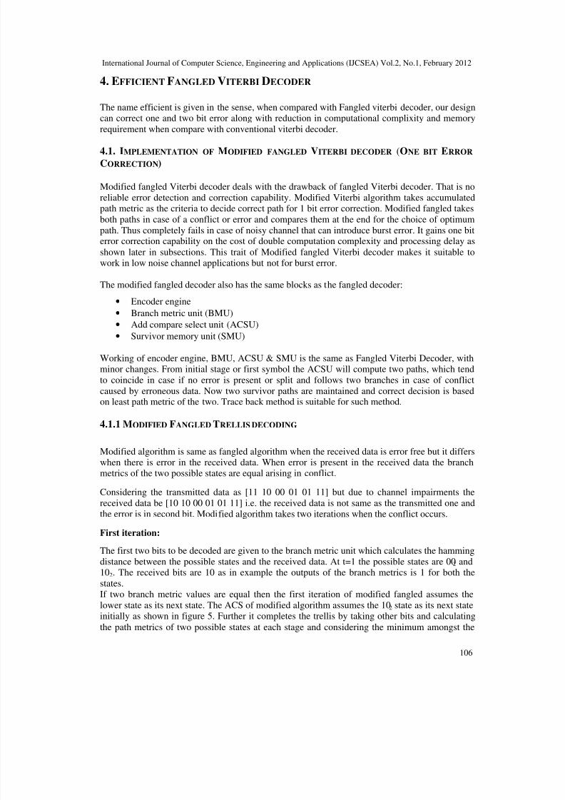
First iteration:
The first two bits to be decoded are given to the branch metric unit which calculates the hamming
distance between the possible states and the received data. At t=1 the possible states are 002 and102. The received bits are 10 as in example the outputs of the branch metrics is 1 for both the
states.If two branch metric values are equal then the first iteration of modified fangled assumes the
lower state as its next state. The ACS of modified algorithm assumes the 102 state as its next stateinitially as shown in figure 5. Further it completes the trellis by taking other bits and calculating
the path metrics of two possible states at each stage and considering the minimum amongst the
8/2/2019 An Efficient Viterbi Decoder
http://slidepdf.com/reader/full/an-efficient-viterbi-decoder 7/16
International Journal of Computer Science, Engineering and Applications (IJCSEA) Vol.2, No.1, February 2012
107
two. Finally the path metric of the first iteration is obtained and is stored. The final path metric
for the first iteration is 1 as in figure 5.
Figure 5. Modified fangled viterbi decoding first iteration.
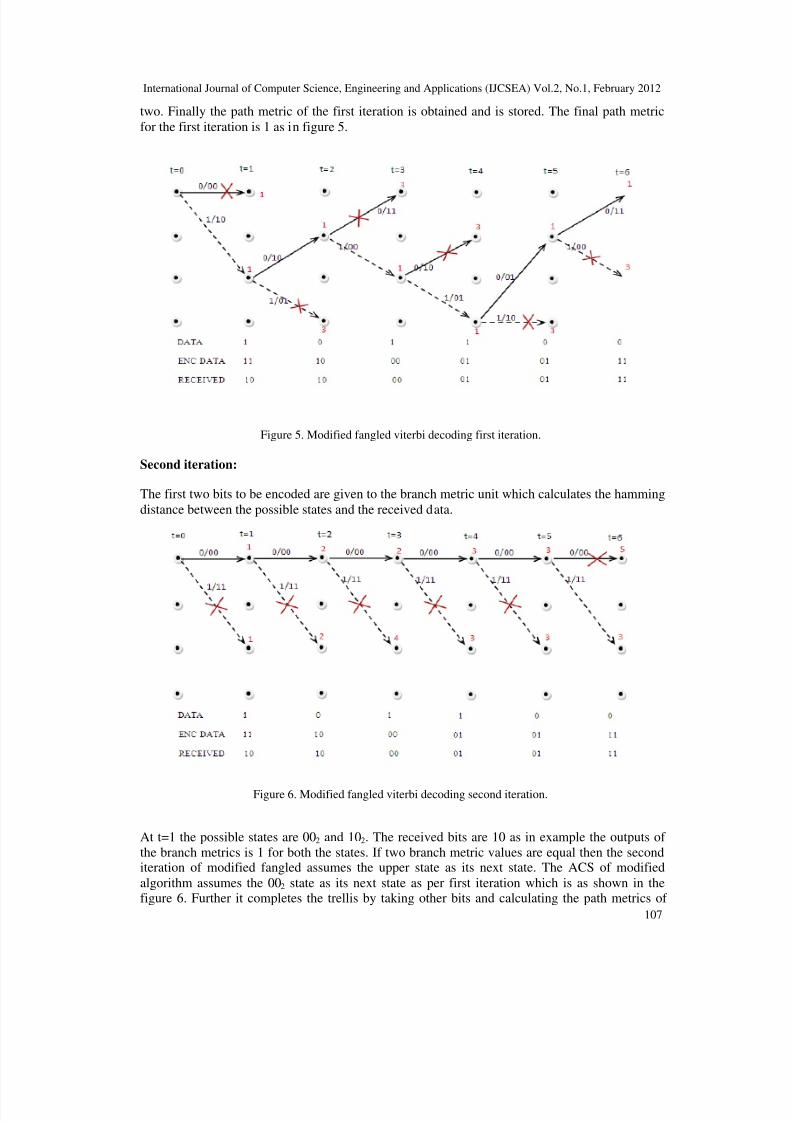
Second iteration:
The first two bits to be encoded are given to the branch metric unit which calculates the hamming
distance between the possible states and the received data.
Figure 6. Modified fangled viterbi decoding second iteration.
At t=1 the possible states are 002 and 102. The received bits are 10 as in example the outputs of
the branch metrics is 1 for both the states. If two branch metric values are equal then the seconditeration of modified fangled assumes the upper state as its next state. The ACS of modified
algorithm assumes the 002 state as its next state as per first iteration which is as shown in thefigure 6. Further it completes the trellis by taking other bits and calculating the path metrics of
8/2/2019 An Efficient Viterbi Decoder
http://slidepdf.com/reader/full/an-efficient-viterbi-decoder 8/16
International Journal of Computer Science, Engineering and Applications (IJCSEA) Vol.2, No.1, February 2012
108
two possible states at each stage and considering the minimum amongst the two. At last the path
metric of the second iteration is obtained and is stored. The final path metric for the seconditeration is 3 and is as shown in figure 6.
Finally after completion of both the iterations two path metrics are obtained which are compared
and minimum out of which is selected as our decoding path. The first path metric is 1 and thesecond path metric is 3, the minimum out of which is selected as the final decoding path. Finally
the decoded data for the above selected path is [101100] which is our encoded data thus modified
fangled scheme resolves the conflicts and gives the optimum result even if the data received is inerror.
4.1.2 RESULTS OF CONVOLUTION ENCODING AND MODIFIED FANGLED DECODING
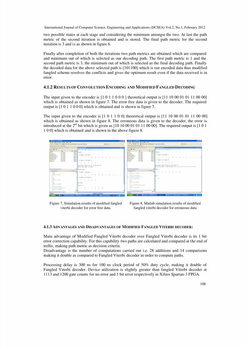
The input given to the encoder is [1 0 1 1 0 0 0 ] theoretical output is [11 10 00 01 01 11 00 00]which is obtained as shown in figure 7. The error free data is given to the decoder. The required
output is [1 0 1 1 0 0 0] which is obtained and is shown in figure 7.
The input given to the encoder is [1 0 1 1 0 0] theoretical output is [11 10 00 01 01 11 00 00]
which is obtained as shown in figure 8. The erroneous data is given to the decoder, the error isintroduced at the 2
ndbit which is given as [10 10 00 01 01 11 00 00]. The required output is [1 0 1
1 0 0] which is obtained and is shown in the above figure 8.
4.1.3 ADVANTAGES AND DISADVANTAGES OF MODIFIED FANGLED VITERBI DECODER:
Main advantage of Modified Fangled Viterbi decoder over Fangled Viterbi decoder is its 1 bit
error correction capability. For this capability two paths are calculated and compared at the end of
trellis, making path metric as decision criteria.Disadvantage is the number of computations carried out i.e. 28 additions and 14 comparisons
making it double as compared to Fangled Viterbi decoder in order to compute paths.
Processing delay is 300 ns for 100 ns clock period of 50% duty cycle, making it double of
Fangled Viterbi decoder. Device utilization is slightly greater than fangled Viterbi decoder at1113 and 1200 gate counts for no error and 1 bit error respectively in Xilinx Spartan-3 FPGA.
Figure 7. Simulation results of modified fangled
viterbi decoder for error free data.
Figure 8. Matlab simulation results of modified
fangled viterbi decoder for erroneous data
8/2/2019 An Efficient Viterbi Decoder
http://slidepdf.com/reader/full/an-efficient-viterbi-decoder 9/16
International Journal of Computer Science, Engineering and Applications (IJCSEA) Vol.2, No.1, February 2012
109
It cannot be used for more than 1 bit error correction. It cannot be used in channel with burst
error, though interleaver and de-interleaver are a solution for this.
Efficient fangled Viterbi decoder can solve most of the disadvantages mentioned above exceptdevice utilization which tends to increase slightly.
4.2 IMPLEMENTATION OF EFFICIENT FANGLED VITERBI DECODER (ONE / TWO BIT
ERROR CORRECTION)
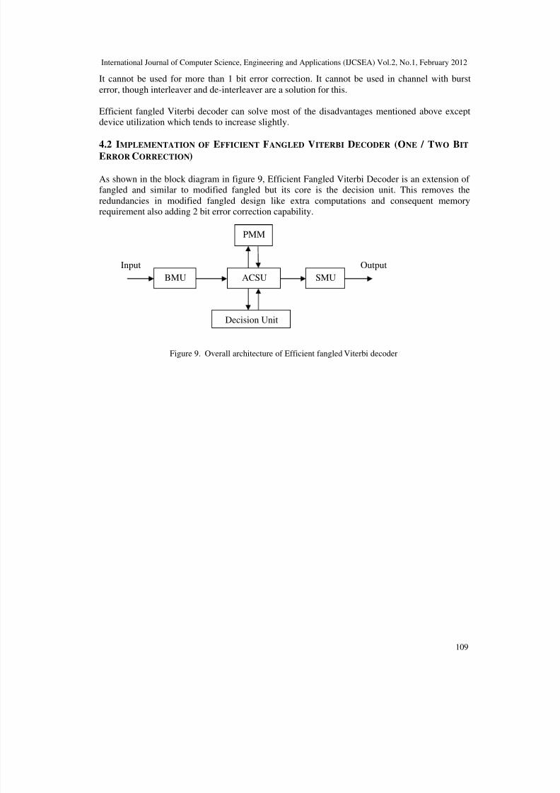
As shown in the block diagram in figure 9, Efficient Fangled Viterbi Decoder is an extension of fangled and similar to modified fangled but its core is the decision unit. This removes the
redundancies in modified fangled design like extra computations and consequent memoryrequirement also adding 2 bit error correction capability.
Figure 9. Overall architecture of Efficient fangled Viterbi decoder
Decision Unit
PMM
ACSU SMUBMU
Input Output
8/2/2019 An Efficient Viterbi Decoder
http://slidepdf.com/reader/full/an-efficient-viterbi-decoder 10/16
International Journal of Computer Science, Engineering and Applications (IJCSEA) Vol.2, No.1, February 2012
110
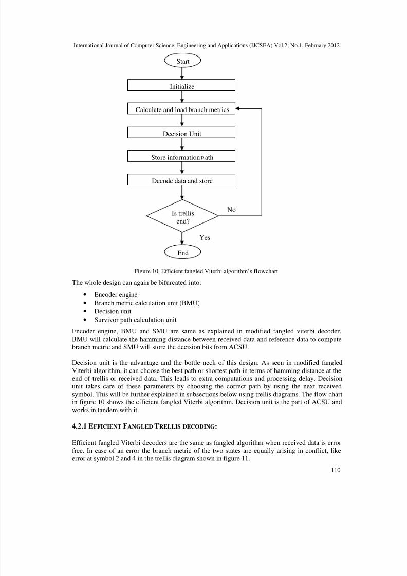
Figure 10. Efficient fangled Viterbi algorithm’s flowchart
The whole design can again be bifurcated into:
• Encoder engine
• Branch metric calculation unit (BMU)• Decision unit
• Survivor path calculation unit
Encoder engine, BMU and SMU are same as explained in modified fangled viterbi decoder.
BMU will calculate the hamming distance between received data and reference data to compute
branch metric and SMU will store the decision bits from ACSU.
Decision unit is the advantage and the bottle neck of this design. As seen in modified fangled
Viterbi algorithm, it can choose the best path or shortest path in terms of hamming distance at theend of trellis or received data. This leads to extra computations and processing delay. Decision
unit takes care of these parameters by choosing the correct path by using the next receivedsymbol. This will be further explained in subsections below using trellis diagrams. The flow chart
in figure 10 shows the efficient fangled Viterbi algorithm. Decision unit is the part of ACSU andworks in tandem with it.
4.2.1 EFFICIENT FANGLED TRELLIS DECODING:
Efficient fangled Viterbi decoders are the same as fangled algorithm when received data is errorfree. In case of an error the branch metric of the two states are equally arising in conflict, like
error at symbol 2 and 4 in the trellis diagram shown in figure 11.
Start
End
Initialize
Calculate and load branch metrics
Decision Unit
Store information ath
Decode data and store
Is trellis
end?
No
Yes
8/2/2019 An Efficient Viterbi Decoder
http://slidepdf.com/reader/full/an-efficient-viterbi-decoder 11/16
International Journal of Computer Science, Engineering and Applications (IJCSEA) Vol.2, No.1, February 2012
111
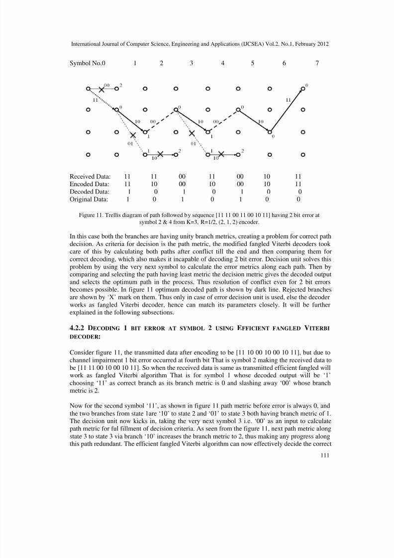
Symbol No.0 1 2 3 4 5 6 7
Received Data: 11 11 00 11 00 10 11Encoded Data: 11 10 00 10 00 10 11
Decoded Data: 1 0 1 0 1 0 0Original Data: 1 0 1 0 1 0 0
Figure 11. Trellis diagram of path followed by sequence [11 11 00 11 00 10 11] having 2 bit error at
symbol 2 & 4 from K=3, R=1/2, (2, 1, 2) encoder.
In this case both the branches are having unity branch metrics, creating a problem for correct path
decision. As criteria for decision is the path metric, the modified fangled Viterbi decoders took care of this by calculating both paths after conflict till the end and then comparing them for
correct decoding, which also makes it incapable of decoding 2 bit error. Decision unit solves this
problem by using the very next symbol to calculate the error metrics along each path. Then bycomparing and selecting the path having least metric the decision metric gives the decoded output
and selects the optimum path in the process. Thus resolution of conflict even for 2 bit errorsbecomes possible. In figure 11 optimum decoded path is shown by dark line. Rejected branches
are shown by ‘X’ mark on them. Thus only in case of error decision unit is used, else the decoder
works as fangled Viterbi decoder, hence can match its parameters closely. It will be furtherexplained in the following subsections.
4.2.2 DECODING 1 BIT ERROR AT SYMBOL 2 USING EFFICIENT FANGLED VITERBI
DECODER:
Consider figure 11, the transmitted data after encoding to be [11 10 00 10 00 10 11], but due to
channel impairment 1 bit error occurred at fourth bit That is symbol 2 making the received data to
be [11 11 00 10 00 10 11]. So when the received data is same as transmitted efficient fangled willwork as fangled Viterbi algorithm That is for symbol 1 whose decoded output will be ‘1’
choosing ‘11’ as correct branch as its branch metric is 0 and slashing away ‘00’ whose branch
metric is 2.
Now for the second symbol ‘11’, as shown in figure 11 path metric before error is always 0, and
the two branches from state 1are ‘10’ to state 2 and ‘01’ to state 3 both having branch metric of 1.The decision unit now kicks in, taking the very next symbol 3 i.e. ‘00’ as an input to calculatepath metric for ful fillment of decision criteria. As seen from the figure 11, next path metric along
state 3 to state 3 via branch ‘10’ increases the branch metric to 2, thus making any progress alongthis path redundant. The efficient fangled Viterbi algorithm can now effectively decide the correct
8/2/2019 An Efficient Viterbi Decoder
http://slidepdf.com/reader/full/an-efficient-viterbi-decoder 12/16
International Journal of Computer Science, Engineering and Applications (IJCSEA) Vol.2, No.1, February 2012
112
path which is along state 2 via branch ‘10’. The algorithm resets the decision criteria i.e. the path
metric to 0, thus making the algorithm usable for 2 bit error correction.
Practical implication of the discussion above is the algorithm’s improvement in computationalcomplexity. As we know that for decoding every symbol ACSU does 2 additions and 1
comparison which make it the bottleneck of the whole system. Use of decision unit which is onlyin the case of error takes 2 additions and 1 comparison as it will compute the two path error
metrics and compare them. And as the requirement to change path arises as in the case of error at
symbol 2, another 2 additions and 1 comparison is required for decoding the correct branch.
4.2.3 DECODING THE SECOND BIT ERROR AT SYMBOL 4 USING EFFICIENT FANGLED
VITERBI DECODER:
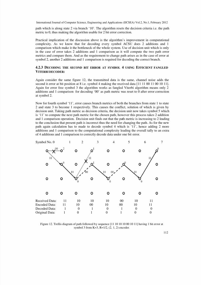
Again consider the same figure 12, the transmitted data is the same, channel noise adds the
second it error at bit position at 8 i.e. symbol 4 making the received data [11 11 00 11 00 10 11].
Again for error free symbol 3 the algorithm works as fangled Viterbi algorithm means only 2additions and 1 comparison for decoding ‘00’ as path metric was reset to 0 after error correction
at symbol 2.
Now for fourth symbol ‘11’, error causes branch metrics of both the branches from state 1 to state
2 and state 3 to become 1 respectively. This causes the conflict, solution of which is given by
decision unit. Taking path metric as decision criteria, the decision unit now takes symbol 5 whichis ‘11’ to compute the next path metric for the chosen path, however this process takes 2 addition
and 1 comparison operation. Decision unit finds out that the path metric is increasing to 2 leading
to the conclusion that present path is incorrect thus the need for changing the path. As for the newpath again calculation has to made to decode symbol 4 which is ‘11’, hence adding 2 more
additions and 1 comparison to the computational complexity leading the overall tally to an extraof 4 additions and 1 comparison to correctly decode data under one bit error.
Symbol No. 0 1 2 3 4 5 6 7
Received Data: 11 10 10 10 00 10 11Encoded Data: 11 10 00 10 00 10 11
Decoded Data: 1 0 1 0 1 0 0Original Data: 1 0 1 0 1 0 0
Figure 12. Trellis diagram of path followed by sequence [11 10 10 10 00 10 11] having 1 bit error at
symbol 3 from K=3, R=1/2, (2, 1, 2) encoder.
8/2/2019 An Efficient Viterbi Decoder
http://slidepdf.com/reader/full/an-efficient-viterbi-decoder 13/16
International Journal of Computer Science, Engineering and Applications (IJCSEA) Vol.2, No.1, February 2012
113
4.2.4 RESULTS OF CONVOLUTION ENCODING AND EFFICIENT FANGLED DECODING
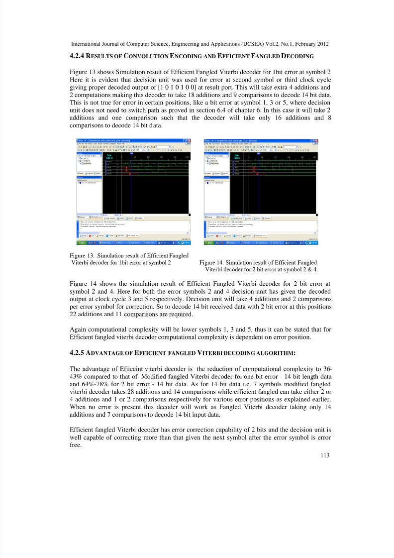
Figure 13 shows Simulation result of Efficient Fangled Viterbi decoder for 1bit error at symbol 2
Here it is evident that decision unit was used for error at second symbol or third clock cyclegiving proper decoded output of [1 0 1 0 1 0 0] at result port. This will take extra 4 additions and
2 computations making this decoder to take 18 additions and 9 comparisons to decode 14 bit data.This is not true for error in certain positions, like a bit error at symbol 1, 3 or 5, where decision
unit does not need to switch path as proved in section 6.4 of chapter 6. In this case it will take 2additions and one comparison such that the decoder will take only 16 additions and 8
comparisons to decode 14 bit data.
Figure 13. Simulation result of Efficient Fangled
Viterbi decoder for 1bit error at symbol 2 Figure 14. Simulation result of Efficient Fangled
Viterbi decoder for 2 bit error at symbol 2 & 4.
Figure 14 shows the simulation result of Efficient Fangled Viterbi decoder for 2 bit error at
symbol 2 and 4. Here for both the error symbols 2 and 4 decision unit has given the decodedoutput at clock cycle 3 and 5 respectively. Decision unit will take 4 additions and 2 comparisons
per error symbol for correction. So to decode 14 bit received data with 2 bit error at this positions22 additions and 11 comparisons are required.
Again computational complexity will be lower symbols 1, 3 and 5, thus it can be stated that for
Efficient fangled viterbi decoder computational complexity is dependent on error position.
4.2.5 ADVANTAGE OF EFFICIENT FANGLED VITERBI DECODING ALGORITHM:
The advantage of Efiiceint viterbi decoder is the reduction of computational complexity to 36-
43% compared to that of Modified fangled Viterbi decoder for one bit error - 14 bit length dataand 64%-78% for 2 bit error - 14 bit data. As for 14 bit data i.e. 7 symbols modified fangled
viterbi decoder takes 28 additions and 14 comparisons while efficient fangled can take either 2 or4 additions and 1 or 2 comparisons respectively for various error positions as explained earlier.
When no error is present this decoder will work as Fangled Viterbi decoder taking only 14
additions and 7 comparisons to decode 14 bit input data.
Efficient fangled Viterbi decoder has error correction capability of 2 bits and the decision unit is
well capable of correcting more than that given the next symbol after the error symbol is errorfree.
8/2/2019 An Efficient Viterbi Decoder
http://slidepdf.com/reader/full/an-efficient-viterbi-decoder 14/16
International Journal of Computer Science, Engineering and Applications (IJCSEA) Vol.2, No.1, February 2012
114
4.3 SHORTCOMING OF EFFICIENT FANGLED VITERBI DECODING ALGORITHM:
Main drawback of this algorithm is its dependency on the accuracy of decision unit rendering itinadequate to deal with burst error symbol data. It must be noted that 2 bit burst errors in the
symbol itself cannot be corrected by using hamming distance (hard decision) decoding. As for
error in consecutive symbols, consider figure 11 where errors in symbol 2 & 4 are corrected by
using symbol 3 and 5 in the decision unit. If by any chance the symbol 3 or 5 would have had anyerror then choice of correct path would have been impossible, as decision unit would be rendered
useless causing the whole decoding algorithm unit to fail, but this problem is only for 2 bit errorcorrection. Solution of this problem is the use of interleaver and de-interleaver only after testing
channel characteristic, or it will make normally distributed error into burst error.
Dependency on next bit leads to the algorithms incapability to correct error on the last symbol asthere is no symbol in the trellis after that. This problem was automatically tackled by padding two
zeros in the encoder, making the last two bits known as 0 prior to decoding them.
5. RESULTS AND CONCLUSSION
While designing a Viterbi decoder in any of its variant, each and every parameter cannot beimproved, hence there always be a tradeoff between them, extent of which is to be decided by the
required performance to be achieved from the decoder. The improvement of some parameters likecomputational complexity, processing time and error correction capability leads to the
degradation of other parameters like increase in device utilization and hard ware complexity.
Fangled Viterbi decoder cannot detect error but can sometimes correct it, while calculating only
one path. It can seen from table 1, that Fangled Viterbi decoder has the lowest computational
complexity and device utilization (only 1019 gate counts) amongst other designs together with
processing time of 150 ns, which is only matched by Efficient fangled Viterbi decoder.Modified Fangled Viterbi decoder was designed as a solution for above problems, by providing
one bit error correction capability. But table 1 clearly shows the tradeoffs it has to make in orderto do so. Computational complexity and processing time have doubled but device utilization
remained almost the same with a small increase of 17%. Modified Fangled Viterbi decodercannot correct 2 bit error.
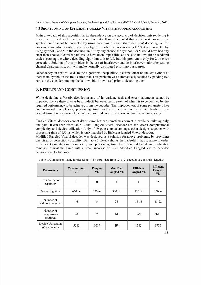
Table 1. Comparison Table for decoding 14 bit input data from (2, 1, 2) encoder of constraint length 3.
Parameters Conventional
VD Fangled
VD Modified
Fangled VD Efficient
Fangled VD Efficient
Fangled
VD Error correction
capability2 0 1 1 2
Processing time 650 ns 150 ns 300 ns 150 ns 150 ns Number of
additions required46 14 28 16-18 18-22
Number of comparisons
required
20 7 14 8-9 9-11 Device Utilization
(Gate counts)5242 1019 1194 1542 1758
8/2/2019 An Efficient Viterbi Decoder
http://slidepdf.com/reader/full/an-efficient-viterbi-decoder 15/16
International Journal of Computer Science, Engineering and Applications (IJCSEA) Vol.2, No.1, February 2012
115
Efficient fangled took these problems and improved them as shown in table 1. When compared
with Fangled Viterbi decoders every other parameter seems to degrade except error correctioncapability which increased two folds to 2 bit. For 1 bit error correction for 14 bit input data, when
compared with Modified fangled Viterbi decoder, computational complexity improved by 36-43% and processing delay was halved but device utilization substantially increased by 51% when
implemented on FPGA Spartan 3. For 2 bit error correction, when compared with modifiedfangled decoder it showed 22-36%.
For 2 bit data it can also be compared to conventional Viterbi decoder, when compared in table 1showed substantial improvements in every parameter. As shown computational complexityimproved by 50-60% for 14 bit received data. Processing time and device utilization of Viterbi
decoder for 2 error correction in 14 bit received data are 4.4 and 3 times respectively, whencompared to Efficient fangled Viterbi decoder.
REFERENCES
[1] Andrew J. Viterbi, Error Bounds for Convolutional Codes and an Asymptotically Optimum Decoding
Algorithm, IEEE Transactions on Information Theory, Volume IT-13, in April, 1967 pages 260-269.
[2] Andrew R Cohen, Jerrold A Heller and Andrew J. Viterbi, A new coding technique for asynchronousmultiple access communication, IEEE Transactions on Communication technology, vol. no. 5,
October 1971.
[3] I.M. Onyszchuk, coding gains and error rates from the Big Viterbi Decoder, TDA progress report,
August 15,1991, pages 42-106.
[4] David Yeh, Gennady Feygin and Paul Chow, RACER: A reconfigurable Constraint-Length 14 Viterbi
Decoder, IEEE 1996.
[5] H. Hayashi, H. Kobayashi, M. Umezawa, S. Hosaka, H. Hirano, Optical Disc Systems Department,
Corporate R&D Laboratories, Pioneer Electronic Corporation, DVD Players using a Viterbi decoding
circuit, IEEE Transactions on Consumer Electronics, Vol. 44, No.2, May 1998.
[6] M. Kivioja, J. Isoaho, L. Vanska, Design and Implementation of Viterbi Decoder with FPGAs,
Journal of VLSI Signal Processing 21, 5–14 (1999).
[7] K He, G Cauwenbergh, Integrated 64-state parallel analog Viterbi decoder, IEEE International
symposium on circuits and systems (ISCAS), Vol. 4, May 28-31, 2000 pages 761-764.
[8] K Chadha, J R Cavallaro, A reconfigurable Viterbi decoder architecture, Asilomar conference onsignals, systems, and computers, November 2001 pages 66-71.
[9] Jon Feldman, Ibrahim Abou-Faycal, Matteo Frigo, A Fast Maximum-Likelihood Decoder for
Convolutional Codes, 2002.
[10] Jang-Hyun Park and Yea Chul Rho, Performance test of Viterbi decoder for Wideband CDMA
system, 2002.
[11] Sriram Swaminathan, Russel Tessier, Dennis Goeckel and Wayne Burleson, A Dynamically
Reconfigurable Adaptive Viterbi Decoder, FPGA 02, Feb 2002, pages 24-26.
[12] M Benaissa, Y Zhu, A novel high-speed configurable Viterbi decoder for broadband access,
EURASIP Journal on Applied signal processing, Vol. 13, 2003, pages 1317-1327.
[13] A. R. Abdul Shakoor, V. Szwarc, and T. A. Kwasniewski, High Speed Viterbi Decoder for W-LAN
and Broadband Applications, IEEE 2004.
[14] R Henning, C Chakrabarti, An approach for adaptively approaximating the Viterbi algorithm toreduce power consumption while decoding convolutional codes, IEEE Transactions on signal
processing, 2004 pages 1-11.[15] J Ou, M K Prasanna, Time and energy efficient Viterbi decoding using FPGAs, IEEE International
conference on Acoustic Speech Processing, 2005.
[16] R Mohammad, K Dimyati, H Harun, Improving FEC performance for baseband signal processing
using a lookup table, ICICS 2005, pages 955-959.
[17] M Guo, M O Ahmad, M N S Swamy, and C Wang, FPGA Design and implementation of a low-
power systolic array-based adaptive Viterbi decoder, IEEE Transactions on circuits and systems-I:
Regular papers, Vol. 52, No. 2, February 2005, pages 350-365.
8/2/2019 An Efficient Viterbi Decoder
http://slidepdf.com/reader/full/an-efficient-viterbi-decoder 16/16
International Journal of Computer Science, Engineering and Applications (IJCSEA) Vol.2, No.1, February 2012
116
[18] S Haene, A Burg, D Perels, P Luethi, N Felber, and W Fichtner, FPGA implementation of Viterbi
decoders for MIMO-BICM, IEEE 2005, pages 734-738.
[19] Behzad Mohmad Heravi and Bahram Honary, Multi-rate Parameterized Viterbi Decoding for Partial
Reconfiguration, PGNet 2006.
[20] Rajaram Sivasubramanian and Abhaikumar Varadhan, An Efficient Implementation of IS-95A
CDMA Transceivers through FPGA, DSP Journal, Volume 6, Issue 1, September, 2006.
[21] Hema.S, Suresh babu.V, Ramesh P, FPGA Implementation of Viterbi Decoder, Proceedings of the6th WSEAS Int. Conf. on Electronics, Hardware, Wireless and Optical Communications, Corfu
Island, Greece, 16-19 February 2007, pages 162-167.
[22] F. Angarita, M. J. Canet, T. Sansaloni, J. Valls and V. Almenar, Architectures for the Implementation
of a OFDM-WLAN Viterbi Decoder, Journal of Signal Processing Systems 52, 2008, pages 35–44.
[23] T Menakadevi and M Madheshwaran, Anna University, Coimbatore, Tamilnadu, design and
implementation of high performance viterbi decoder for mobile communication data security,
Computer intelligence in security for information systems, 2009, pages 69-76.
[24] C Arun and V Rajamani of Sri Venkateswara College of Engineering, Chennai, Design and VLSI
architecture of non-polynomial based low probability of error Viterbi decoder, Journal of scientific
and industrial research, vol. 68, February 2009, pages 97-106.
[25] K He, G Cauwenbergh, “Integrated 64 state parallel analog Viterbi decoder”, IEEE international
symposium on circuit and system (ISCAS), Vol. 4, May 28-31, 2000, pages 761-764.
[26] Hema S, Suresh Babu V, Ramesh P, “FPGA implementation of Viterbi decoder”, Proceedings of the
6th WSEAS international Conference on Electronics, Hardware, Wireless and optical communication,Corfu Island, Feb-16-19, 2007, Pages 162-167.
[27] M Bennaisa, Y Zhu, “A novel high speed configurable Viterbi decoder for broadband access’,
EURASIP journal on Applied signal processing, Vol. 13, 2003 pages 1317-1327.
Authors
Arunlal. K. S received his BSc and MSc degrees in Electronics from Kannur University, Kannur
and M. G. University, Kottayam, India in 2003 and 2005 respectively also MS degree in Mobile
Communication & Internet Technologies from Mangalore University, Mangalore, India in 2010,
and pursuing his Ph.D from VTU Belgaum. He is currently with R. V. Center for Cognitive
Technologies Bangalore as Research Scholar. His current research interests include MIMO and
digital communications systems.
Dr. S. A. Hariprasad received his BE and ME degree in Electronics & Communication from
Mysore University, Mysore, and Bangalore University, Bangalore, India in 1991 and 2000
respectively. He received his Ph.D degree in Digital controllers from Avinashilingum University,
Coimbatore, India in 2011. He is currently Director of R. V. Center for Cognitive Technologies
Bangalore and Associate Professor in Department of Electronics & Communication at R. V.
College of Engineering Bangalore, India. He has published more than 26 papers in recognized
journals and conferences. His recent research concentrates on Digital Controllers, RF
Engineering.