Embed Size (px)
Citation preview
LogiCORE™ IP Viterbi Decoder v7.0
User Guide
UG745 (v1.0) October 18, 2010
Viterbi Decoder v7.0 User Guide www.xilinx.com UG745 (v1.0) October 18, 2010
Xilinx is providing this product documentation, hereinafter “Information,” to you “AS IS” with no warranty of any kind, express or implied. Xilinx makes no representation that the Information, or any particular implementation thereof, is free from any claims of infringement. You are responsible for obtaining any rights you may require for any implementation based on the Information. All specifications are subject to change without notice.
XILINX EXPRESSLY DISCLAIMS ANY WARRANTY WHATSOEVER WITH RESPECT TO THE ADEQUACY OF THE INFORMATION OR ANY IMPLEMENTATION BASED THEREON, INCLUDING BUT NOT LIMITED TO ANY WARRANTIES OR REPRESENTATIONS THAT THIS IMPLEMENTATION IS FREE FROM CLAIMS OF INFRINGEMENT AND ANY IMPLIED WARRANTIES OF MERCHANTABILITY OR FITNESS FOR A PARTICULAR PURPOSE.
Except as stated herein, none of the Information may be copied, reproduced, distributed, republished, downloaded, displayed, posted, or transmitted in any form or by any means including, but not limited to, electronic, mechanical, photocopying, recording, or otherwise, without the prior written consent of Xilinx.
© 2010 Xilinx, Inc. XILINX, the Xilinx logo, Artix, ISE, Kintex, Spartan, Virtex, and other designated brands included herein are trademarks of Xilinx in the United States and other countries. MATLAB and Simulink are registered trademarks of The MathWorks, Inc. All other trademarks are the property of their respective owners.
Revision HistoryThe following table shows the revision history for this document.
Date Version Revision
10/18/10 1.0 Initial Xilinx release.
UG745 (v1.0) October 18, 2010 www.xilinx.com Viterbi Decoder v7.0 User Guide
Table of Contents
Revision History . . . . . . . . . . . . . . . . . . . . . . . . . . . . . . . . . . . . . . . . . . . . . . . . . . . . . . . . . . . . . 2
Preface: About This GuideGuide Contents . . . . . . . . . . . . . . . . . . . . . . . . . . . . . . . . . . . . . . . . . . . . . . . . . . . . . . . . . . . . . . 5Conventions . . . . . . . . . . . . . . . . . . . . . . . . . . . . . . . . . . . . . . . . . . . . . . . . . . . . . . . . . . . . . . . . . 6
Typographical . . . . . . . . . . . . . . . . . . . . . . . . . . . . . . . . . . . . . . . . . . . . . . . . . . . . . . . . . . . . . 6Online Document . . . . . . . . . . . . . . . . . . . . . . . . . . . . . . . . . . . . . . . . . . . . . . . . . . . . . . . . . . 7
Chapter 1: IntroductionScope . . . . . . . . . . . . . . . . . . . . . . . . . . . . . . . . . . . . . . . . . . . . . . . . . . . . . . . . . . . . . . . . . . . . . . . . 9System Requirements . . . . . . . . . . . . . . . . . . . . . . . . . . . . . . . . . . . . . . . . . . . . . . . . . . . . . . . . 9About the Core . . . . . . . . . . . . . . . . . . . . . . . . . . . . . . . . . . . . . . . . . . . . . . . . . . . . . . . . . . . . . . 10Recommended Design Experience . . . . . . . . . . . . . . . . . . . . . . . . . . . . . . . . . . . . . . . . . . . 10Technical Support. . . . . . . . . . . . . . . . . . . . . . . . . . . . . . . . . . . . . . . . . . . . . . . . . . . . . . . . . . . 10Feedback. . . . . . . . . . . . . . . . . . . . . . . . . . . . . . . . . . . . . . . . . . . . . . . . . . . . . . . . . . . . . . . . . . . . 11
Chapter 2: Licensing the CoreLicense Options . . . . . . . . . . . . . . . . . . . . . . . . . . . . . . . . . . . . . . . . . . . . . . . . . . . . . . . . . . . . . 13
Full System Hardware Evaluation . . . . . . . . . . . . . . . . . . . . . . . . . . . . . . . . . . . . . . . . . . 13Full . . . . . . . . . . . . . . . . . . . . . . . . . . . . . . . . . . . . . . . . . . . . . . . . . . . . . . . . . . . . . . . . . . . . . 13
Obtaining Your License Key. . . . . . . . . . . . . . . . . . . . . . . . . . . . . . . . . . . . . . . . . . . . . . . . . 14Full System Hardware Evaluation License . . . . . . . . . . . . . . . . . . . . . . . . . . . . . . . . . . . 14Full License Key . . . . . . . . . . . . . . . . . . . . . . . . . . . . . . . . . . . . . . . . . . . . . . . . . . . . . . . . . . 14
Installing the License File . . . . . . . . . . . . . . . . . . . . . . . . . . . . . . . . . . . . . . . . . . . . . . . . . . . 14
Chapter 3: Getting StartedGenerating the IP Using Core Generator . . . . . . . . . . . . . . . . . . . . . . . . . . . . . . . . . . . . . 15
Project Navigator . . . . . . . . . . . . . . . . . . . . . . . . . . . . . . . . . . . . . . . . . . . . . . . . . . . . . . . . . 16System Generator . . . . . . . . . . . . . . . . . . . . . . . . . . . . . . . . . . . . . . . . . . . . . . . . . . . . . . . . . . . 16Viterbi Decoder Example Designs . . . . . . . . . . . . . . . . . . . . . . . . . . . . . . . . . . . . . . . . . . . 17Synthesis and Implementation . . . . . . . . . . . . . . . . . . . . . . . . . . . . . . . . . . . . . . . . . . . . . . 18
Setting Up for Simulation . . . . . . . . . . . . . . . . . . . . . . . . . . . . . . . . . . . . . . . . . . . . . . . . . . 18Functional Simulation . . . . . . . . . . . . . . . . . . . . . . . . . . . . . . . . . . . . . . . . . . . . . . . . . . . . . 18
Chapter 4: Functional DescriptionCore Overview . . . . . . . . . . . . . . . . . . . . . . . . . . . . . . . . . . . . . . . . . . . . . . . . . . . . . . . . . . . . . . 19Feature Overview . . . . . . . . . . . . . . . . . . . . . . . . . . . . . . . . . . . . . . . . . . . . . . . . . . . . . . . . . . . 20Viterbi Type . . . . . . . . . . . . . . . . . . . . . . . . . . . . . . . . . . . . . . . . . . . . . . . . . . . . . . . . . . . . . . . . 20Decoder Options . . . . . . . . . . . . . . . . . . . . . . . . . . . . . . . . . . . . . . . . . . . . . . . . . . . . . . . . . . . . 20
Constraint Length . . . . . . . . . . . . . . . . . . . . . . . . . . . . . . . . . . . . . . . . . . . . . . . . . . . . . . . . 20Traceback. . . . . . . . . . . . . . . . . . . . . . . . . . . . . . . . . . . . . . . . . . . . . . . . . . . . . . . . . . . . . . . . 21
UG745 (v1.0) October 18, 2010 www.xilinx.com Viterbi Decoder v7.0 User Guide
Latency. . . . . . . . . . . . . . . . . . . . . . . . . . . . . . . . . . . . . . . . . . . . . . . . . . . . . . . . . . . . . . . . . . 21Architecture . . . . . . . . . . . . . . . . . . . . . . . . . . . . . . . . . . . . . . . . . . . . . . . . . . . . . . . . . . . . . 21Best State . . . . . . . . . . . . . . . . . . . . . . . . . . . . . . . . . . . . . . . . . . . . . . . . . . . . . . . . . . . . . . . . 21Data Format . . . . . . . . . . . . . . . . . . . . . . . . . . . . . . . . . . . . . . . . . . . . . . . . . . . . . . . . . . . . . 21Code Rate and Convolutional Code . . . . . . . . . . . . . . . . . . . . . . . . . . . . . . . . . . . . . . . . . 22Packet Handling . . . . . . . . . . . . . . . . . . . . . . . . . . . . . . . . . . . . . . . . . . . . . . . . . . . . . . . . . . 22
Puncturing and Erasure . . . . . . . . . . . . . . . . . . . . . . . . . . . . . . . . . . . . . . . . . . . . . . . . . . . . . 22BER . . . . . . . . . . . . . . . . . . . . . . . . . . . . . . . . . . . . . . . . . . . . . . . . . . . . . . . . . . . . . . . . . . . . . . . . . 23Normalization . . . . . . . . . . . . . . . . . . . . . . . . . . . . . . . . . . . . . . . . . . . . . . . . . . . . . . . . . . . . . . 23Synchronization . . . . . . . . . . . . . . . . . . . . . . . . . . . . . . . . . . . . . . . . . . . . . . . . . . . . . . . . . . . . 23Multi-channel . . . . . . . . . . . . . . . . . . . . . . . . . . . . . . . . . . . . . . . . . . . . . . . . . . . . . . . . . . . . . . . 23Trellis Coded Modulation . . . . . . . . . . . . . . . . . . . . . . . . . . . . . . . . . . . . . . . . . . . . . . . . . . . 24Dual Decoder . . . . . . . . . . . . . . . . . . . . . . . . . . . . . . . . . . . . . . . . . . . . . . . . . . . . . . . . . . . . . . . 25Latency . . . . . . . . . . . . . . . . . . . . . . . . . . . . . . . . . . . . . . . . . . . . . . . . . . . . . . . . . . . . . . . . . . . . . 25Calculating Throughput . . . . . . . . . . . . . . . . . . . . . . . . . . . . . . . . . . . . . . . . . . . . . . . . . . . . . 25Design Guidelines . . . . . . . . . . . . . . . . . . . . . . . . . . . . . . . . . . . . . . . . . . . . . . . . . . . . . . . . . . 26
Data Format . . . . . . . . . . . . . . . . . . . . . . . . . . . . . . . . . . . . . . . . . . . . . . . . . . . . . . . . . . . . . 26Data Input . . . . . . . . . . . . . . . . . . . . . . . . . . . . . . . . . . . . . . . . . . . . . . . . . . . . . . . . . . . . . . . 26Best State . . . . . . . . . . . . . . . . . . . . . . . . . . . . . . . . . . . . . . . . . . . . . . . . . . . . . . . . . . . . . . . . 26Control Signals . . . . . . . . . . . . . . . . . . . . . . . . . . . . . . . . . . . . . . . . . . . . . . . . . . . . . . . . . . . 26RDY . . . . . . . . . . . . . . . . . . . . . . . . . . . . . . . . . . . . . . . . . . . . . . . . . . . . . . . . . . . . . . . . . . . . 27NORM Signals . . . . . . . . . . . . . . . . . . . . . . . . . . . . . . . . . . . . . . . . . . . . . . . . . . . . . . . . . . . 27BER and Normalization Thresholds . . . . . . . . . . . . . . . . . . . . . . . . . . . . . . . . . . . . . . . . . 27Keep it Registered . . . . . . . . . . . . . . . . . . . . . . . . . . . . . . . . . . . . . . . . . . . . . . . . . . . . . . . . 27
Viterbi Decoder Non-features Summary . . . . . . . . . . . . . . . . . . . . . . . . . . . . . . . . . . . . . 27Multi-channel BER . . . . . . . . . . . . . . . . . . . . . . . . . . . . . . . . . . . . . . . . . . . . . . . . . . . . . . . . 27Log Likelihood Ratio . . . . . . . . . . . . . . . . . . . . . . . . . . . . . . . . . . . . . . . . . . . . . . . . . . . . . . 27De-puncturing . . . . . . . . . . . . . . . . . . . . . . . . . . . . . . . . . . . . . . . . . . . . . . . . . . . . . . . . . . . 27Trellis Mode . . . . . . . . . . . . . . . . . . . . . . . . . . . . . . . . . . . . . . . . . . . . . . . . . . . . . . . . . . . . . 28Factors Affecting BER Performance . . . . . . . . . . . . . . . . . . . . . . . . . . . . . . . . . . . . . . . . . 28
Chapter 5: Troubleshooting Viterbi Issues
Appendix A: References
Viterbi Decoder v7.0 User Guide www.xilinx.com 5UG745 (v1.0) October 18, 2010
Preface
About This Guide
The LogiCORE™ IP Viterbi Decoder User Guide provides information about generating a Viterbi decoder core and customizing and simulating the core using provided examples. It also includes advice on designing with the core and troubleshooting tips.
There are five example designs provided with the user guide to aid in understanding the Viterbi decoder. Each example consists of an ISE project, a configuration file that instantiates the cores, a top level module for the instantiated core and the convolutional encoder, a test bench to simulate the design, and any data files if required.
The examples are provided in a zip file UG745_v01.zip
Guide ContentsThis manual contains the following chapters:
• Chapter 1, Introduction, introduces the core and provides related information about system requirements, recommended design experience, obtaining technical support, and submitting feedback to Xilinx.
• Chapter 2, Licensing the Core, describes the available license options for the core and how to obtain them.
• Chapter 3, Getting Started, explains how to generate the core either through CORE Generator™ technology or as part of an ISE® software project. Included is a summary of Viterbi decoder design examples.
• Chapter 4, Functional Description, provides detailed information about the core and includes a core overview, feature overview, and design guidelines.
• Chapter 5, Troubleshooting Viterbi Issues, recommends actions that may be taken to deal with issues associated with the core.
• Appendix A, References, lists product pages and documents cited in this user guide.
6 www.xilinx.com Viterbi Decoder v7.0 User GuideUG745 (v1.0) October 18, 2010
Preface: About This Guide
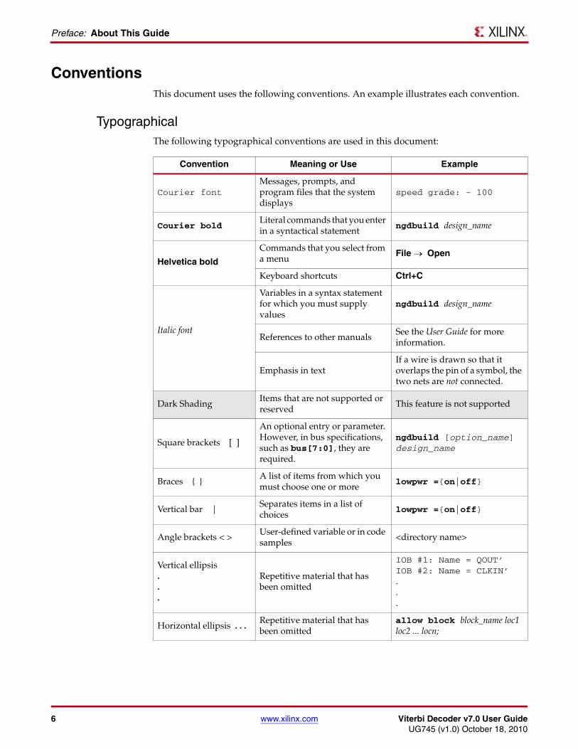
ConventionsThis document uses the following conventions. An example illustrates each convention.
TypographicalThe following typographical conventions are used in this document:
Convention Meaning or Use Example
Courier fontMessages, prompts, and program files that the system displays
speed grade: - 100
Courier boldLiteral commands that you enter in a syntactical statement
ngdbuild design_name
Helvetica bold
Commands that you select from a menu
File → Open
Keyboard shortcuts Ctrl+C
Italic font
Variables in a syntax statement for which you must supply values
ngdbuild design_name
References to other manualsSee the User Guide for more information.
Emphasis in textIf a wire is drawn so that it overlaps the pin of a symbol, the two nets are not connected.
Dark ShadingItems that are not supported or reserved
This feature is not supported
Square brackets [ ]
An optional entry or parameter. However, in bus specifications, such as bus[7:0], they are required.
ngdbuild [option_name] design_name
Braces { }A list of items from which you must choose one or more
lowpwr ={on|off}
Vertical bar | Separates items in a list of choices
lowpwr ={on|off}
Angle brackets < >User-defined variable or in code samples
<directory name>
Vertical ellipsis...
Repetitive material that has been omitted
IOB #1: Name = QOUT’ IOB #2: Name = CLKIN’...
Horizontal ellipsis . . .Repetitive material that has been omitted
allow block block_name loc1 loc2 ... locn;
Viterbi Decoder v7.0 User Guide www.xilinx.com 7UG745 (v1.0) October 18, 2010
Conventions
Online DocumentThe following conventions are used in this document:
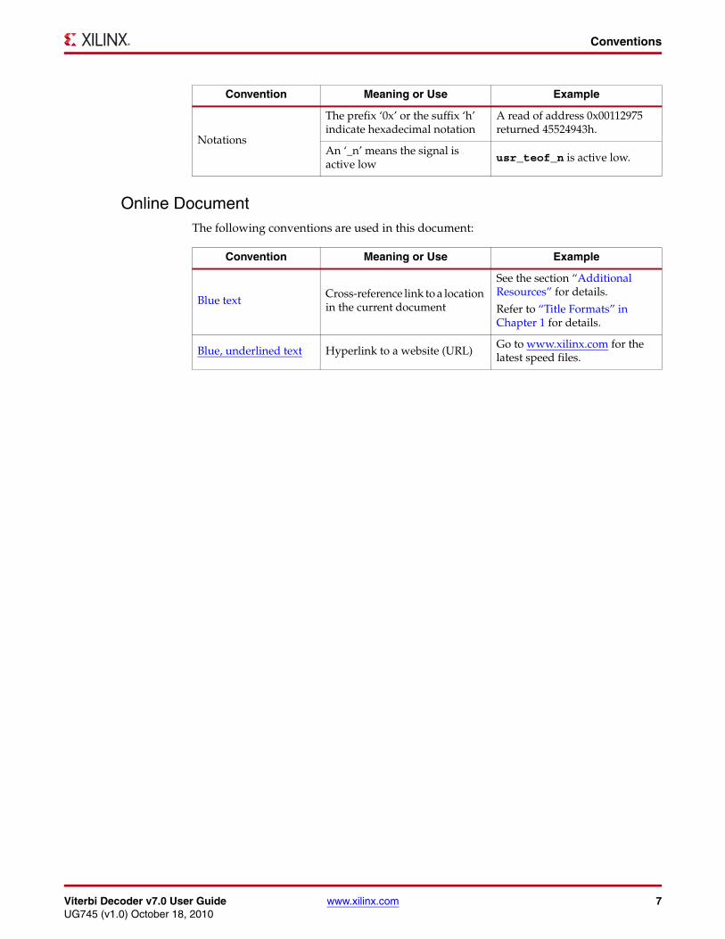
Notations
The prefix ‘0x’ or the suffix ‘h’ indicate hexadecimal notation
A read of address 0x00112975 returned 45524943h.
An ‘_n’ means the signal is active low
usr_teof_n is active low.
Convention Meaning or Use Example
Convention Meaning or Use Example
Blue textCross-reference link to a location in the current document
See the section “Additional Resources” for details.
Refer to “Title Formats” in Chapter 1 for details.
Blue, underlined text Hyperlink to a website (URL)Go to www.xilinx.com for the latest speed files.

8 www.xilinx.com Viterbi Decoder v7.0 User GuideUG745 (v1.0) October 18, 2010
Preface: About This Guide
Viterbi Decoder v7.0 User Guide www.xilinx.com 9UG745 (v1.0) October 18, 2010
Chapter 1
Introduction
ScopeIn modern communication systems, there is a requirement to transmit data and recover it, without error, in the presence of noise. This prevents having to retransmit the data, if there are errors, which would reduce the data rate in the system. One technique used is convolutional coding. A convolutional encoder [Ref 2] and Viterbi decoder [Ref 1] are used together to provide the error correction. The convolutional encoder adds redundancy to the original data, and in the presence of noise the Viterbi decoder uses maximum likelihood decoding to recover the data.
The convolutional encoder encodes the input data. A typical code rate for an encoder is 1/2, which signifies that for each input bit there are two output bits from the encoder. Similarly, for a code rate 1/3, each input bit has three output bits. Generator polynomials are used to encode each output bit from the convolutional encoder, thereby providing error protection for the input data. The encoder implementation consists of XOR gates and shift registers.
The Viterbi decoder is configured to the same parameters as the encoder – code rate, constraint length, and the generator polynomials. The format of the input data to the Viterbi decoder can be either hard or soft coding. A hard code is a binary value, whereas a soft code has a number of levels to reflect the strength, and hence confidence level, of the input data. This allows the Viterbi decoder to know how strong a “1” or “0” can be, which results in a better error protection. The output of the Viterbi decoder is the original data that was input into the encoder.
The Viterbi decoding process operates on continuous data stream, but can work with packets of data. However, this does require a different configuration of the Viterbi Decoder.
The LogiCORE™ IP Viterbi decoder [Ref 1] is a fully-verified solution that supports Verilog-HDL and VHDL. The example designs in this guide are provided in VHDL formats.
This chapter introduces the core and provides related information including recommended design experience, additional resources, technical support advice, and how to submit feedback to Xilinx.
System RequirementsTo determine the operating system support, see UG631, ISE Design Suite 12: Installation, Licensing, and Release Notes [Ref 5].
10 www.xilinx.com Viterbi Decoder v7.0 User GuideUG745 (v1.0) October 18, 2010
Chapter 1: Introduction
About the CoreThe Viterbi decoder core is an IP core available in Xilinx CORE Generator™ software. For detailed information about the core, see the Viterbi Decoder product page.
For information about licensing options, see Chapter 2, Licensing the Core.
Recommended Design ExperienceAlthough the Viterbi decoder is a fully verified solution, the challenge associated with implementing a complete communication system varies depending on the application. For best results, previous experience building high performance, pipelined FPGA designs using Xilinx implementation software and user constraints files (UCFs) is recommended. An appreciation of communication theory involving Viterbi algorithm, trellis diagrams, BER curves, and convolutional encoding is a useful prerequisite for using the core within a communications system. While not necessary to use the core, the recommended experience would help in making correct choices in selecting the most suitable implementation of the core.
Technical SupportIf technical support is required for the core, please submit a WebCase from www.xilinx.com/support/clearexpress/websupport.htm.
To facilitate a faster response, the following information should be provided when submitting a WebCase:
• Details of the issue.
• XCO File: The configuration file for the core.
• ISE® Project: The ISE project if this exists.
• User test bench: The test bench in which the core is used as well as any DO script files used for simulation.
• Original data, or data files: The data prior to it being encoded.
• Encoded data files: The data that was encoded and sent to the Viterbi decoder. This can be used with the original data to debug the issue.
• The channel model used to inject errors: Is this an AWGN core or a simple injection of errors.
• The problem: What is the issue? Is it a core issue or a systems problem, for example BER.
• System Generator
• The MDL design file
• Any data MAT files
• Simulink® software files if required
Viterbi Decoder v7.0 User Guide www.xilinx.com 11UG745 (v1.0) October 18, 2010
Feedback
FeedbackXilinx welcomes comments and suggestions about the Viterbi decoder core and the documentation supplied with the core.
For comments or suggestions about the Viterbi decoder, please submit a WebCase from www.xilinx.com/support/clearexpress/websupport.htm.
Be sure to include the following information:
• Product name
• Core version number
• Explanation of your comments
For comments or suggestions about this document, please submit a WebCase from www.xilinx.com/support/clearexpress/websupport.htm.
Be sure to include the following information:
• Document title
• Document number
• Page number(s) to which your comments refer
• Explanation of your comments

12 www.xilinx.com Viterbi Decoder v7.0 User GuideUG745 (v1.0) October 18, 2010
Chapter 1: Introduction
Viterbi Decoder v7.0 User Guide www.xilinx.com 13UG745 (v1.0) October 18, 2010
Chapter 2
Licensing the Core
This chapter provides instructions for obtaining a license for the Viterbi decoder core, which you must do before using the core in your designs. The Viterbi decoder core is provided under the terms of the Xilinx LogiCORE™ IP Site License Agreement, which conforms to the terms of the SignOnce IP License standard defined by the Common License Consortium.
License OptionsThe Viterbi decoder core provides two licensing options: Evaluation and Full. After installing the required Xilinx ISE® software and IP Service Packs, a license will be required to generate and use the Viterbi decoder. To generate a license, go to the Viterbi Decoder product page.
Full System Hardware EvaluationThe Full System Hardware Evaluation license is available at no cost and lets you fully integrate the core into an FPGA design, place and route the design, evaluate timing, and perform back-annotated gate-level simulation of the core using the demonstration test bench provided with the user guide. In addition, the license key lets you generate a bitstream from the placed and routed design, which can then be downloaded to a supported device and tested in hardware. The core can be tested in the target device for a limited time before timing out (ceasing to function). The time depends upon clock speed and is of the order of two hours, at which time if it ceases to function. The design can be reactivated by reconfiguring the device.
FullThe Full license key is available when you purchase the core and provides full access to all core functionality, both in simulation and in hardware, including:
• Functional simulation support
• Back-annotated gate-level simulation support
• Full implementation support including place-and-route and bitstream generation
• Full functionality in the programmed device with no time-outs
14 www.xilinx.com Viterbi Decoder v7.0 User GuideUG745 (v1.0) October 18, 2010
Chapter 2: Licensing the Core
Obtaining Your License KeyThis section contains information about obtaining either an evaluation or a full license key.
Full System Hardware Evaluation LicenseTo obtain a Full System Hardware Evaluation license:
1. Navigate to the Viterbi Decoder product page.
2. Click Evaluate.
3. Follow the instructions to install the required Xilinx ISE software and IP Service Packs.
Full License KeyTo obtain a Full license key, you must purchase a license for the core. After you purchase a license, a product entitlement is added to your Product Licensing Account on the Xilinx Product Download and Licensing site. The Product Licensing Account Administrator for your site will receive an email from Xilinx with instructions on how to access a Full license and a link to access the licensing site. You can obtain a full key through your account administrator, or your administrator can give you access so that you can generate your own keys. Further details can be found at www.xilinx.com/products/ipcenter/ipaccess_fee.htm.
Installing the License FileFor both the Full System Hardware Evaluation license and the Full license, an email will be sent to you containing instructions for installing your license file. Additional details about IP license key installation can be found in UG631, ISE Design Suite 12: Installation, Licensing, and Release Notes [Ref 5].
Viterbi Decoder v7.0 User Guide www.xilinx.com 15UG745 (v1.0) October 18, 2010
Chapter 3
Getting Started
This chapter provides an overview of how to generate the core. Subsequent sections describe how to simulate and implement designs using the provided design examples.
Generating the IP Using Core GeneratorTo generate a Viterbi decoder using the Xilinx CORE Generator™ software:
1. Start CORE Generator. For help, choose Help → CORE Generator Help.
2. Choose File → New Project.
3. Type a directory name.
4. Set the following project options:
• Part Options From Target Architecture: Select the desired family. For a list of supported families, see the Viterbi Decoder Data Sheet available from the Viterbi Decoder product page.
Note: If an unsupported silicon family is selected, the core will appear grayed out in the taxonomy tree.
• Generation Options For Design Entry: Select either Verilog or VHDL. For Vendor, select Other for XST.
5. After creating the project, locate the core in one of the following ways:
• Look in the taxonomy tree under one of the following:
- Communications & Network → Error Correction
- Communications & Network → Telecommunications
• Type Viterbi in the “Search IP Catalog” edit box.
6. Double-click Viterbi Decoder v7.0 to display the main Viterbi decoder screen.
7. In the Component Name field, enter a name for the core instance.
8. After selecting the desired features and parameters, click Finish. See Chapter 4, Functional Description, for more details on parameters to select.
• The core and its supporting files are generated in the project directory.
• For detailed information about the example design files and directories, see Viterbi Decoder Example Designs in this chapter.
16 www.xilinx.com Viterbi Decoder v7.0 User GuideUG745 (v1.0) October 18, 2010
Chapter 3: Getting Started
Project Navigator1. Open ISE® Project Navigator.
2. Choose File → Create a New Project.
3. Select the relevant part from the Device Properties window.
4. In the Create New Source window, select the New Source tab.
5. In the Select Source Type, select the IP (CORE Generator & Architecture Wizard). Type in a name.
6. Double-click on either of the following:
• Communications & Network → Error Correction
• Communications & Network → Telecommunications
7. Select Viterbi Decoder v7.0 and select Next.
8. Click Finish to create and open the ISE project.
System Generator System Generator for DSP is the industry's leading high-level tool for designing high-performance DSP systems using FPGAs. It provides system modeling and automatic code generation from Simulink® and MATLAB® software (The Mathworks, Inc.) into hardware components of a DSP system. See www.xilinx.com/tools/sysgen.htm.
System Generator provides Xilinx Blockset that contains building blocks for constructing DSP and other digital systems in FPGAs using Simulink. The blocks are grouped into libraries according to their function, and some blocks with broad applicability (for example, the Gateway I/O blocks) are linked into multiple libraries. Viterbi Decoder 7.0 block is listed in the Communications and Index Xilinx Blockset libraries. The parameters described in this user guide also apply to the System Generator Viterbi decoder. However, the examples referred to in this document apply only to the CORE Generator Library.
Viterbi Decoder v7.0 User Guide www.xilinx.com 17UG745 (v1.0) October 18, 2010
Viterbi Decoder Example Designs
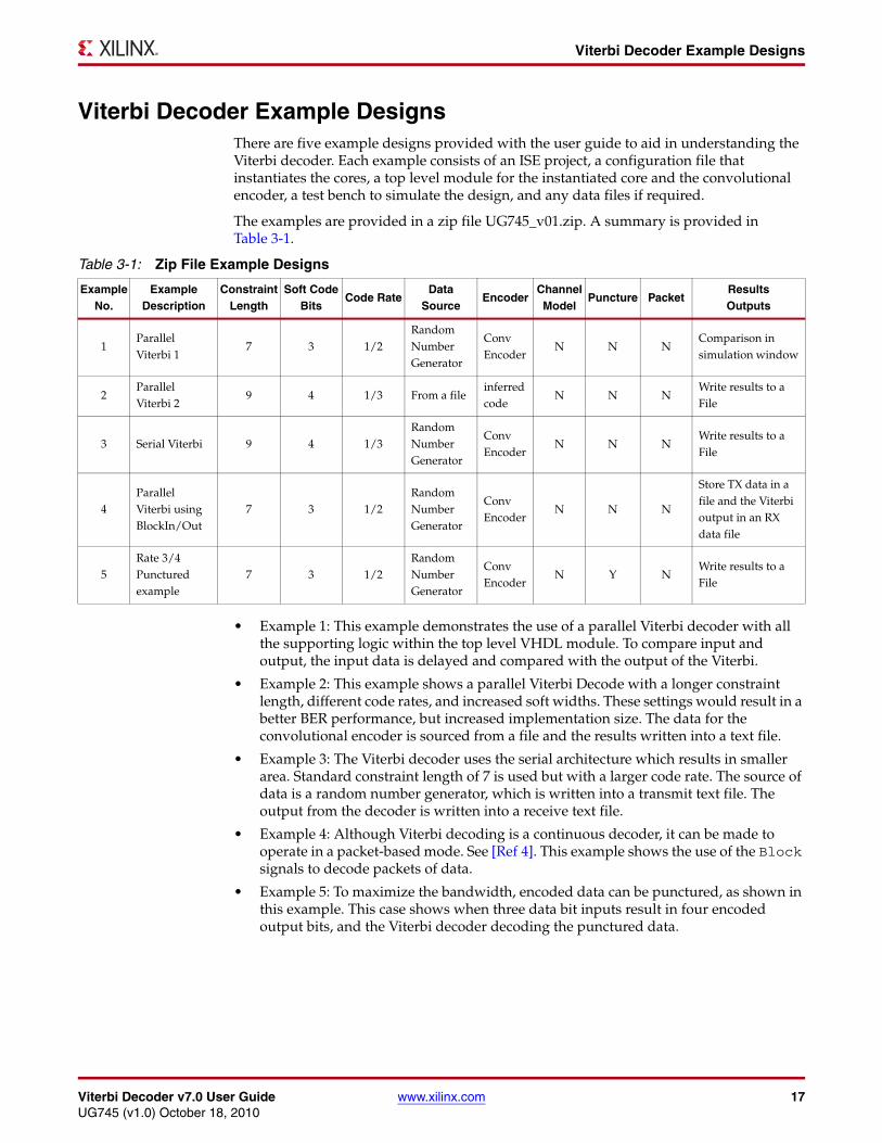
Viterbi Decoder Example DesignsThere are five example designs provided with the user guide to aid in understanding the Viterbi decoder. Each example consists of an ISE project, a configuration file that instantiates the cores, a top level module for the instantiated core and the convolutional encoder, a test bench to simulate the design, and any data files if required.
The examples are provided in a zip file UG745_v01.zip. A summary is provided in Table 3-1.
• Example 1: This example demonstrates the use of a parallel Viterbi decoder with all the supporting logic within the top level VHDL module. To compare input and output, the input data is delayed and compared with the output of the Viterbi.
• Example 2: This example shows a parallel Viterbi Decode with a longer constraint length, different code rates, and increased soft widths. These settings would result in a better BER performance, but increased implementation size. The data for the convolutional encoder is sourced from a file and the results written into a text file.
• Example 3: The Viterbi decoder uses the serial architecture which results in smaller area. Standard constraint length of 7 is used but with a larger code rate. The source of data is a random number generator, which is written into a transmit text file. The output from the decoder is written into a receive text file.
• Example 4: Although Viterbi decoding is a continuous decoder, it can be made to operate in a packet-based mode. See [Ref 4]. This example shows the use of the Block signals to decode packets of data.
• Example 5: To maximize the bandwidth, encoded data can be punctured, as shown in this example. This case shows when three data bit inputs result in four encoded output bits, and the Viterbi decoder decoding the punctured data.
Table 3-1: Zip File Example Designs
ExampleNo.
ExampleDescription
ConstraintLength
Soft CodeBits
Code RateData
SourceEncoder
ChannelModel
Puncture PacketResultsOutputs
1Parallel Viterbi 1
7 3 1/2Random Number Generator
Conv Encoder
N N NComparison in simulation window
2Parallel Viterbi 2
9 4 1/3 From a fileinferred code
N N NWrite results to a File
3 Serial Viterbi 9 4 1/3Random Number Generator
Conv Encoder
N N NWrite results to a File
4Parallel Viterbi using BlockIn/Out
7 3 1/2Random Number Generator
Conv Encoder
N N N
Store TX data in a file and the Viterbi output in an RX data file
5Rate 3/4 Punctured example
7 3 1/2Random Number Generator
Conv Encoder
N Y NWrite results to a File
18 www.xilinx.com Viterbi Decoder v7.0 User GuideUG745 (v1.0) October 18, 2010
Chapter 3: Getting Started
Synthesis and ImplementationThe ISE project is used to process the example design through the Xilinx tool flow. Generally the examples have a data source, convolutional encoder, Viterbi decoder, and compare logic.
The ISE project includes the following files within the project:
1. XCO file for the Viterbi decoder
2. XCO file for the Convolutional Encoder
3. HDL files for the core
4. HDL test bench
The ISE project is used as follows:
1. A UniSim model is created from the XCO files.
2. HDL example design files are synthesized using XST.
3. Ngdbuild is run to consolidate the core netlist and the example design netlist into the NGD file containing the entire design.
4. Design is mapped to the target technology.
5. Design is placed-and-routed on the target device.
6. Static timing analysis is performed on the routed design using trce.
7. A bitstream is generated.
8. A simulation can be run from the ISE project using the files created.
The Xilinx tool flow generates several output and report files that are saved in the directories.
Setting Up for SimulationThe ISE project is set up for simulation using the ISim simulator. See the Functional Simulation section for more information.
Functional SimulationTo run a VHDL functional simulation of the example designs, select the behavioral simulation option in the ISE project. In the Process window, double-click on Simulate Behavioral Model. This selection results in ISim opening, running the scripts, and opening a wave window to indicate the various signals in the design and the test bench.
Viterbi Decoder v7.0 User Guide www.xilinx.com 19UG745 (v1.0) October 18, 2010
Chapter 4
Functional Description
The Viterbi decoder is used in many Forward Error Correction (FEC) applications and in systems where data are transmitted and subject to errors before reception. The Viterbi decoder is compatible with many common standards, such as DVB, 3GPP2, 3GPP LTE, IEEE 802.16, Hiperlan, and Intelsat IESS-308/309.
The following sections provide a summary of the core. For further details, see the Viterbi Decoder Data Sheet available from the Viterbi Decoder product page.
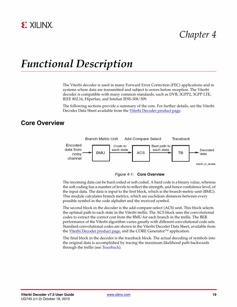
Core Overview
The incoming data can be hard coded or soft coded. A hard code is a binary value, whereas the soft coding has a number of levels to reflect the strength, and hence confidence level, of the input data. The data is input to the first block, which is the branch-metric-unit (BMU). This module calculates branch metrics, which are euclidean distances between every possible symbol in the code alphabet and the received symbol.
The second block in the decoder is the add-compare-select (ACS) unit. This block selects the optimal path to each state in the Viterbi trellis. The ACS block uses the convolutional codes to extract the correct cost from the BMU for each branch in the trellis. The BER performance of the Viterbi algorithm varies greatly with different convolutional code sets. Standard convolutional codes are shown in the Viterbi Decoder Data Sheet, available from the Viterbi Decoder product page, and the CORE Generator™ application.
The final block in the decoder is the traceback block. The actual decoding of symbols into the original data is accomplished by tracing the maximum likelihood path backwards through the trellis (see Traceback).
X-Ref Target - Figure 4-1
Figure 4-1: Core Overview
20 www.xilinx.com Viterbi Decoder v7.0 User GuideUG745 (v1.0) October 18, 2010
Chapter 4: Functional Description
Feature OverviewThe summary features for the Viterbi decoder are as follows:
• Parameterizable decoder rates, constraint length, convolution codes and traceback lengths
• Choice of either parallel architecture for high data throughput, or serial for smaller area footprint
• Very low latency option
• Soft decision with parameterizable soft width
• Other architectural options such as multi-channel decoding, dual rate decoder or trellis mode
• Erasure for external puncturing
• Synchronization via the BER monitor and Normalization
• Packet handling
The following sections correspond to the flow of the Viterbi Decoder graphical user interface and provide a summary of the parameters. More detail can be found in the Viterbi Decoder Data Sheet available from the Viterbi Decoder product page.
Viterbi TypeThere are four options available for the type of Viterbi used:
• Standard: This is a straightforward usage of the IP and is the one generally used.
• Multi-channel: If there are a number of interlaced channels, they can be decoded simultaneously using the same decoder and therefore save area.
• Trellis mode: This is used with Trellis Coded Modulation (TCM), or Pragmatic Trellis Coded Modulation (PTCM). See the Trellis Coded Modulation section.
• Dual decoder: This is the solution if there is a requirement for two decoders that have the same constraint length and traceback, but different convolution codes or rates, and the need to save area. See the Dual Decoder section.
Decoder Options
Constraint LengthThe constraint length is specified here. This can be obtained from the communication standard being implemented. The most common length is 7. For an increase of 1 in constraint length, the ACS requirements double. The higher the constraint length, the better the error correcting performance; however, this results in an increase in the size of the Viterbi decoder. Therefore the maximum length tends to be 9.
The examples with the User Guide use these two common constraint lengths.
Viterbi Decoder v7.0 User Guide www.xilinx.com 21UG745 (v1.0) October 18, 2010
Decoder Options
TracebackThe traceback length determines the length of the training sequence for the Viterbi decoder. A few things to note:
• The length of the traceback is parameterizable and can be set to any value between 12 and 128.
• If the Reduced Latency option is selected, the value must be between 12 and 126 and divisible by 6.
• The recommended value for non-punctured decoding is at least six times the constraint length.
• For punctured data, the length should be at least twelve times the constraint length. This is twice the traceback length of a non-punctured core because so much information has been lost, and hence a longer training sequence is required to find the correct path through the trellis.
• While increasing the traceback length improves the error correcting capability of the Viterbi decoder, it also results in an increase in RAM requirements.
LatencyAs a rough guide, the latency of the Viterbi tends to be approximately four times the traceback length.
If latency is an issue, use the Reduced Latency option to reduce the latency on the core by approximately half.
ArchitectureFor the “standard” and “dual decoder” type, there are two main architectures choices:
• Parallel: Larger but with a higher performance. Hence used for high data rates.
• Serial: Serial processing of the input data resulting in a smaller architecture. Used with lower data rates.
For the parallel architecture, see Example 1 or Example 2; for the serial architecture, Example 3 shows the operation of the core.
For the multi-channel and trellis mode, only the parallel architecture is available.
Best StateAs part of the traceback process, to recover the data sent by the encoder the Viterbi decoder can select the starting position in the trellis. This can be either state zero, a state with the best path metric, or, if using packet data, a fixed user input state.
Data FormatThere are two data-coding formats for the incoming data: Hard coding and Soft coding. A hard code is equivalent to a binary value – high or low. Soft coding is used to give a confidence level of the input data to the Viterbi.
Soft-coded data gives a significantly better BER performance compared with hard-coded data. Soft-decision offers approximately a 3 dB increase in coding gain over hard-decision decoding and so should be the preferred choice.
22 www.xilinx.com Viterbi Decoder v7.0 User GuideUG745 (v1.0) October 18, 2010
Chapter 4: Functional Description
For soft coding, the usual bit width is 3 bits. There is a small improvement, ~0.25 dB, from 3 to 4 bits, but any increase in soft width can have an impact in size and speed of the decoder. However, above four bits there is very little BER improvement. There are two data formats for soft coding:
• Signed Magnitude: The signed magnitude data format uses the MSB as a sign bit. The lower bits are used to represent the strength of probability of being a 0 or 1. A higher number in the lower bits will represent a stronger 1/0 than a lower number.
• Offset Binary: With offset binary, all the bits are used to represent a number where a low number represents the strongest 0 and a high number represent the strongest 1. The values in between represent the strength of the 0 or 1.
In both cases, the soft width can be extended to provide more bits as well as more resolution in defining the strengths of 0s or 1s.
Code Rate and Convolutional CodeThe most used code rates are 1/2 and 1/3. Other code rates up to 1/7 can also be selected. The Viterbi decoder does not have any internal puncturing capability, but can decode punctured data by use of the erase inputs. See Puncturing and Erasure and Example 5 in Table 3-1.
Packet HandlingViterbi decoding is a continuous operation, but the input to the Viterbi can be packet-based rather than continuous streams. A simple way of telling the Viterbi to use blocks of data as opposed to using a continuous stream is to use the BlockIn/Out signals. These signals are marker signals and do not change the way the Viterbi operates. See Example 4 in Table 3-1 for how to use the various control signals. For standards like IEEE 802.16 and LTE, the use of packets is more complicated, for example tail biting. In this case, the packets have to be terminated correctly. The termination techniques the Viterbi can use are:
• Trellis truncation
• Trellis termination
• Tail biting
When implementing a packet-based decoder, this is an important area to consider. Therefore, for a full description of the Viterbi decoder and trellis termination and tail-biting, see Xilinx application note XAPP551, Viterbi Decoder Block Decoding - Trellis Termination and Tail Biting [Ref 4].
Puncturing and ErasureIf the data has been punctured prior to transmission, de-puncturing is carried out externally to the Viterbi decoder. The bit positions where the punctured data was are now filled with null symbols, which are indicated using the erasure input.
In punctured mode, the decoder functions exactly as a non-punctured Viterbi decoder. Some points to note:
• There is an erasure input for each data input. For example, for a code rate 1/2, there are two data inputs, and for the Viterbi to deal with punctured data there would be two erasure inputs to indicate the position of the null symbols.
• Erasure can be used with the standard, multi-channel and dual decoder.
Viterbi Decoder v7.0 User Guide www.xilinx.com 23UG745 (v1.0) October 18, 2010
BER
• Erasure is not an option for the trellis mode decoder.
The recommendation is that the puncturing/de-puncturing be done externally so as to be able to select any puncture rate. For an example of puncturing, see Example 5 in Table 3-1.
BERThe bit-error-rate (BER) option on the decoder monitors the error rate on the transmission channel.
• The number of input symbols, over which the number of errors are counted, can be set. For punctured data, the NULL symbols positions are not included in the error count.
• The BER output always has a width of 16; therefore the maximum number of errors that can be counted is 65535 symbols. For errors above this value, the BER output saturates to all 1s.
NormalizationIf there are errors in the channel, the metrics within the ACS will increase, and a point will be reached when there is a chance of overflow. To avoid this, a fixed value is subtracted from all the metrics, and so the metrics are normalized. To monitor this normalization, the NORM signal, which is an optional output, indicates the frequency of the normalization. A high normalization rate (exceeding a certain threshold) indicates loss of synchronization. A low normalization rate (less than a certain threshold) indicates Viterbi synchronization has been achieved.
SynchronizationTo monitor the synchronization status of the core, the Viterbi decoder uses the normalization rate and the BER value. Either of these parameters exceeding a predetermined threshold can indicate a loss of synchronization. The reason to use both parameters is to achieve a synchronization independent of Eb/No. There are example determined thresholds in the Viterbi Decoder Data Sheet available from the Viterbi Decoder product page, but if unique values are to be used, a full simulation with AWGN channel would be required.
To monitor the two main thresholds, there are three out-of-synchronization (OOS) flags provided:
• To indicate the BER threshold has been exceeded
• To indicate the normalization threshold has been exceeded
• To indicate the core is in a low noise state.
Multi-channelThe multi-channel decoder decodes many interlaced channels using a single Viterbi decoder. The mode is useful when dealing with a number of lower data rate channels, and it has the advantage that is saves FPGA resources.
• The multi-channel decoder can decode from 2 to 32 channels.
• The input data to the multi-channel decoder should be interlaced encoded data on each data input.
24 www.xilinx.com Viterbi Decoder v7.0 User GuideUG745 (v1.0) October 18, 2010
Chapter 4: Functional Description
• The output is interlaced decoded data on the DATA_OUT pin with channel 1 first followed by channel 2.
• The larger the number of channels, the greater the block RAM requirements, as each channel requires its own traceback.
• The BER from the multi-channel decoder, if selected, gives the average number of errors present over all the input channels.
• The output rate of the decoder is equal to the speed divided by the number of channels.
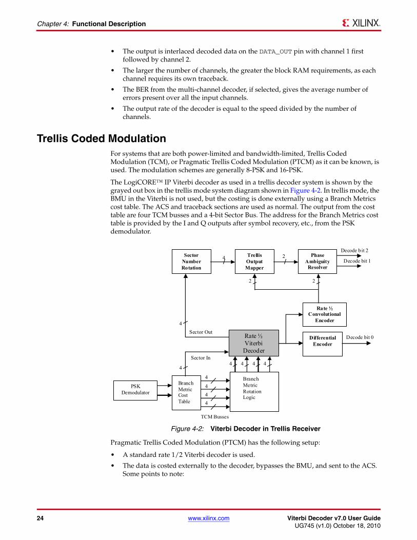
Trellis Coded ModulationFor systems that are both power-limited and bandwidth-limited, Trellis Coded Modulation (TCM), or Pragmatic Trellis Coded Modulation (PTCM) as it can be known, is used. The modulation schemes are generally 8-PSK and 16-PSK.
The LogiCORE™ IP Viterbi decoder as used in a trellis decoder system is shown by the grayed out box in the trellis mode system diagram shown in Figure 4-2. In trellis mode, the BMU in the Viterbi is not used, but the costing is done externally using a Branch Metrics cost table. The ACS and traceback sections are used as normal. The output from the cost table are four TCM busses and a 4-bit Sector Bus. The address for the Branch Metrics cost table is provided by the I and Q outputs after symbol recovery, etc., from the PSK demodulator.
Pragmatic Trellis Coded Modulation (PTCM) has the following setup:
• A standard rate 1/2 Viterbi decoder is used.
• The data is costed externally to the decoder, bypasses the BMU, and sent to the ACS. Some points to note:
X-Ref Target - Figure 4-2
Figure 4-2: Viterbi Decoder in Trellis Receiver
Sector
Number Rotation
Rate ½ Viterbi
Decoder
TrellisOutput Mapper
Phase Ambiguity
Resolver
Rate ½ Convolutional
Encoder
PSK
Demodulator
Differential Encoder
4
4 4 4
4 4 4
2
Branch Metric Cost Table
Branch Metric Rotation Logic
TCM Busses
Sector In
4
Sector Out 4
2
Decode bit 2
Decode bit 1
Decode bit 0
4
4 2
Viterbi Decoder v7.0 User Guide www.xilinx.com 25UG745 (v1.0) October 18, 2010
Dual Decoder
• Each TCM bus can be 4 to 9 bits wide depending upon the TCM bus width selected on the Viterbi decoder.
• The 4 to 9 bits are unsigned cost values that are applied to the ACS module in the Viterbi decoder. If the width of the generated costs is less than the (soft width+1), then the data should be tied to the lower bits and the remaining TCM input bits tied to zero.
• The received symbol or phase angle is converted to four branch metrics and a sector number externally to the decoder using an external lookup table.
• The sector number identifies the part of the I-Q plane where the symbol was received. The branch metrics are then processed by the trellis mode decoder. The sector number is delayed by the Viterbi latency in the trellis mode decoder.
Dual DecoderFor the same constraint length and traceback length, the core can function as a dual decoder.
• This allows two different internal sets of convolutional codes and two different output rates to be specified.
• The dual decoder offers significant area savings as only one core is used.
• The dual decoder can be implemented as either parallel or serial architecture, and erasure pins can be present on the input.
• The selection of the decoder rate and codes is through a SEL pin.
LatencyThe latency of the core depends primarily on the traceback and constraint lengths. The latency is given by the number of symbol inputs between DATA_IN, validated by CE, or ND in the serial case, and the decoded data result output on DATA_OUT validated by RDY. The general equation is as follows:
Latency = n*traceback_length+constraint_length
where n = 2 for reduced latency and 4 for all other cases.
The total latency figure is dependent on many other factors such as Best State, for example, and to get the total latency the Viterbi decoder should be simulated.
Calculating Throughput For parallel non-punctured mode and external punctured mode, the data rate equals clock rate. For example, if the clock is 250 MHz, the symbol rate is 250 Msymbols/second.
For serial architecture the data rate is:
Data rate = (clock rate / (soft bit + output rate + 6))
Therefore, if the clock is 200 MHz, the soft width = 3 and the output rate is 2.
Symbol rate = 220 MHz (clock rate) /(3(soft width)+2 (output rate)+6) = 220/ 11 = 20 Mbps
26 www.xilinx.com Viterbi Decoder v7.0 User GuideUG745 (v1.0) October 18, 2010
Chapter 4: Functional Description
Design GuidelinesThe following section provide guidelines on the best design practices for inclusion of the LogiCORE IP Viterbi decoder within a system.
Data FormatUse soft coding, as this will give a better BER performance. For the soft coding width, 3 or 4 bits should be sufficient. If the width is any larger, it will increase the size of the ACS but not give a large improvement in BER performance.
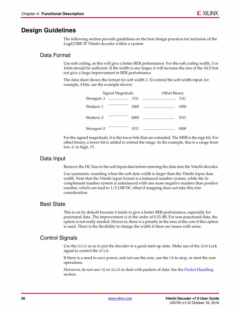
The data sheet shows the format for soft width 3. To extend the soft width input, for example, 4 bits, see the example shown:
For the signed magnitude, it is the lower bits that are extended. The MSB is the sign bit. For offset binary, a lower bit is added to extend the range. In the example, this is a range from low, 0, to high, 15.
Data InputRemove the DC bias in the soft input data before entering the data into the Viterbi decoder.
Use symmetric rounding when the soft data width is larger than the Viterbi input data width. Note that the Viterbi input format is a balanced number system, while the 2s complement number system is unbalanced with one more negative number than positive number, which can lead to 1/2 LSB DC offset if mapping does not take this into consideration.
Best StateThis is on by default because it tends to give a better BER performance, especially for punctured data. The improvement is in the order of 0.25 dB. For non-punctured data, the option is not really needed. However, there is a penalty in the area of the core if this option is used. There is the flexibility to change the width if there are issues with noise.
Control SignalsUse the SCLR so as to put the decoder in a good start-up state. Make use of the DCM Lock signal to control the SCLR.
If there is a need to save power, and not use the core, use the CE to stop, or start the core operations.
However, do not use CE or SLCR to deal with packets of data. See the Packet Handling section.
Signed Magnitude Offset BinaryStrongest..1 ..................... 1111 ................................... 1111
Weakest..1.....................
1000 .................................. 1000
Weakest..0.....................
0000 .................................. 0111
Strongest..0.....................
0111 .................................. 0000
Viterbi Decoder v7.0 User Guide www.xilinx.com 27UG745 (v1.0) October 18, 2010
Viterbi Decoder Non-features Summary
If dealing with blocks of data, use the BlockIn/Out signals. To qualify the output data AND the RDY and BlockOut signals together.
RDY Use the ready signal (RDY) to validate the data. This signal could be used as a clock enable to store the output from the Viterbi decoder, for example, in a FIFO or memory.
NORM SignalsUse the NORM signal to get an idea of the errors in the Viterbi and how it is dealing with the internal path metrics. If it is a noisy system, there will be normalizing of the metrics and a NORM pulse will appear.
BER and Normalization ThresholdsThe BER and Normalization thresholds are needed to achieve synchronization. The Viterbi Decoder Data Sheet available from the Viterbi Decoder product page gives some example thresholds. If there is a requirement to have flexibility in the system dynamic, BER and Normalization thresholds can be used. These threshold ports can be selected and exposed via the Viterbi decoder GUI. To have maximum flexibility, the threshold values could be set via a register under microprocessor control.
Keep it RegisteredTo simplify timing and increase system performance in an FPGA design, keep everything registered, that is, all inputs and outputs from the user application should come from, or connect to, a flip-flop. While registering signals may not be possible for all paths, it simplifies timing analysis.
Viterbi Decoder Non-features SummaryThis section outlines the features that may be external to the core, depending upon the system being implemented.
Multi-channel BERIf there is a requirement for individual BER circuits, these would have to be done externally to the core.
Log Likelihood RatioThe LLR values that create the soft code inputs have to be generated externally to the core. See resources on the internet for information on how to do this.
De-puncturingThe Viterbi decoder does not do any kind of internal de-puncturing. Any de-puncturing will have to be external. See Example 5 in Table 3-1.
28 www.xilinx.com Viterbi Decoder v7.0 User GuideUG745 (v1.0) October 18, 2010
Chapter 4: Functional Description
Trellis Mode In this mode, the external costing table will have to created.
Factors Affecting BER PerformanceWhen viewing the Viterbi decoder as part of a whole communication system, there are a few parameters that could affect BER performance. For the core, parameters such as data format, constraint length, and traceback length, use of best state will have an affect. However, these will generally be determined by the standard being implemented. Once these have been taken care of, then outside factors need to be taken into consideration, for example modulation type, the channel model used, Eb/No value, convolutional codes, and DC bias. For factors that affect packets of data, see Xilinx application note XAPP551, Viterbi Decoder Block Decoding - Trellis Termination and Tail Biting [Ref 4].
Viterbi Decoder v7.0 User Guide www.xilinx.com 29UG745 (v1.0) October 18, 2010
Chapter 5
Troubleshooting Viterbi Issues
If a Viterbi decoder is not functioning as expected, here are some tips to consider. Xilinx Technical Support may also be contacted.
1. Refer to examples provided to see if they match your configuration.
2. If not, create a simple design based on parameters using just an encoder and the Viterbi decoder.
3. Check that parameters of the encoder and Viterbi agree for code rate and convolutional codes. Confirm that the codes are not the wrong way around.
4. Check that the soft width data format is set up correctly, that is, signed or offset, and that the data format for the data input to the decoder is correct, for example, the MSB on the data input is the sign bit for signed magnitude.
5. Add BER and NORM ports to monitor errors. Monitor the OOS signals and see which threshold is being exceeded.
6. Run the decoder in both functional simulation and post-PAR simulation.
7. To speed testing, consider the use of a ChipScope™ analyzer or HW Cosim to find the errors.
If a ChipScope analyzer is used, monitor the following signals:
• Data Inputs
• SCLR
• RDY
• NORM
• BER and BER DONE signal
• OOS signals
For punctured code, ensure:
• Erase input is used
For packet data:
• Block In
• Block Out
• All other signals used with packets as outlined in Xilinx application note XAPP551, Viterbi Decoder Block Decoding - Trellis Termination and Tail Biting [Ref 4]
8. Check the simulation.
If only functional is working correctly, then check timing simulation. See UG626, Synthesis and Simulation Design Guide [Ref 6].

30 www.xilinx.com Viterbi Decoder v7.0 User GuideUG745 (v1.0) October 18, 2010
Chapter 5: Troubleshooting Viterbi Issues
Viterbi Decoder v7.0 User Guide www.xilinx.com 31UG745 (v1.0) October 18, 2010
Appendix A
References
The following product pages and documents are referred to in this user guide:
1. Viterbi Decoder product page
2. Convolutional Encoder product page
3. UG628, Command Line Tools User Guide
4. XAPP551, Viterbi Decoder Block Decoding - Trellis Termination and Tail Biting
5. UG631, ISE Design Suite 11: Installation, Licensing, and Release Notes
6. UG626, Synthesis and Simulation Design Guide