Embed Size (px)
Citation preview

Addendum toUSM2.5 Status Monitor Technical Manual
Effective: July, 2002
®
ActernaEmbedded Transponder
ActernaEmbedded Transponder
Alpha Technologies

PowerAlpha Technologies. Protecting The Power in Communications.

3018-041-C0-002 Rev. B
Acterna Embedded TransponderInstallation Manual
018-041-C0-002, Rev B
Effective Date: July, 2002
© 2002 by Alpha Technologies
NOTE: Photographs contained in this manual are for illustrative purposesonly. These photographs may not exactly match your installation.
NOTE: Review the drawings and illustrations contained in this manual beforeproceeding. If there are questions regarding the safe operation ofthis powering system, please contact Alpha Technologies or yournearest Alpha representative.
Contacting Alpha Technologies:
For general product information and customer service
1-800-863-3930(7:00 AM to 5:00 PM Pacific Time )
For complete technical support
1-800-863-3364 (7:00 AM to 5:00 PM Pacific Time, or 24/7 emergency support)
™
018-041-C0-002 Rev. B4
Table of Contents1. Installation .................................................................................................................5
1.1 Installation in an XM Series 2 Power Supply ......................................... 51.2 Transponder Inputs and Outputs ............................................................ 71.3 Battery Monitor Connections ................................................................. 81.4 Generator Connection ......................................................................... 151.5 Generator Ignition Battery Connection ................................................. 161.6 COMM and RF Connections................................................................ 17
2. Specifications ........................................................................................................... 182.1 Channel Parameters ............................................................................ 18
3. Troubleshooting ........................................................................................................ 193.1 Troubleshooting ................................................................................... 19
4. Part Numbers ........................................................................................................... 204.1 Cable Kit Options ................................................................................ 20
Figure 1-1 Transponder Installation .........................................................................................6Figure 1-2 Input / Output Connections ....................................................................................7Figure 1-3 Battery Monitor Connections for three 48Vdc battery packs ..................................8Figure 1-4 Battery Monitor Connections for two 48Vdc battery packs ....................................9Figure 1-5 Battery Monitor Connections for one 48Vdc battery pack .................................... 10Figure 1-6 Battery Monitor Connections for one 36Vdc battery pack .................................... 11Figure 1-7 Battery Monitor Connections for two 36Vdc battery packs .................................. 12Figure 1-8 Battery Monitor Connections for three 36Vdc battery packs ................................ 13Figure 1-9 Battery Monitor Connections for four 36Vdc battery packs .................................. 14Figure 1-10 Generator Monitor Connections ........................................................................... 15Figure 1-11 Generator Ignition Battery Connection ................................................................. 16Figure 1-12 COMM / RF Connections .................................................................................... 17Table 2-1 Channel Parameters ............................................................................................ 18Table 4-1 Cable kit part numbers ........................................................................................ 20
List of Tables and Figures
5018-041-C0-002 Rev. B
1. Installation
1.1 Installation in an XM Series 2 Power Supply
1. Record the transponder address.
2. Open the power supply enclosure.
NOTE: Backup power will not beavailable while batteriesare disconnected.
3. Set the battery breaker on the front of the powersupply to the OFF position.
4. Unplug all connectors on the front of the powersupply inverter module.
5. Loosen the thumb screws holding the invertermodule into the power supply.
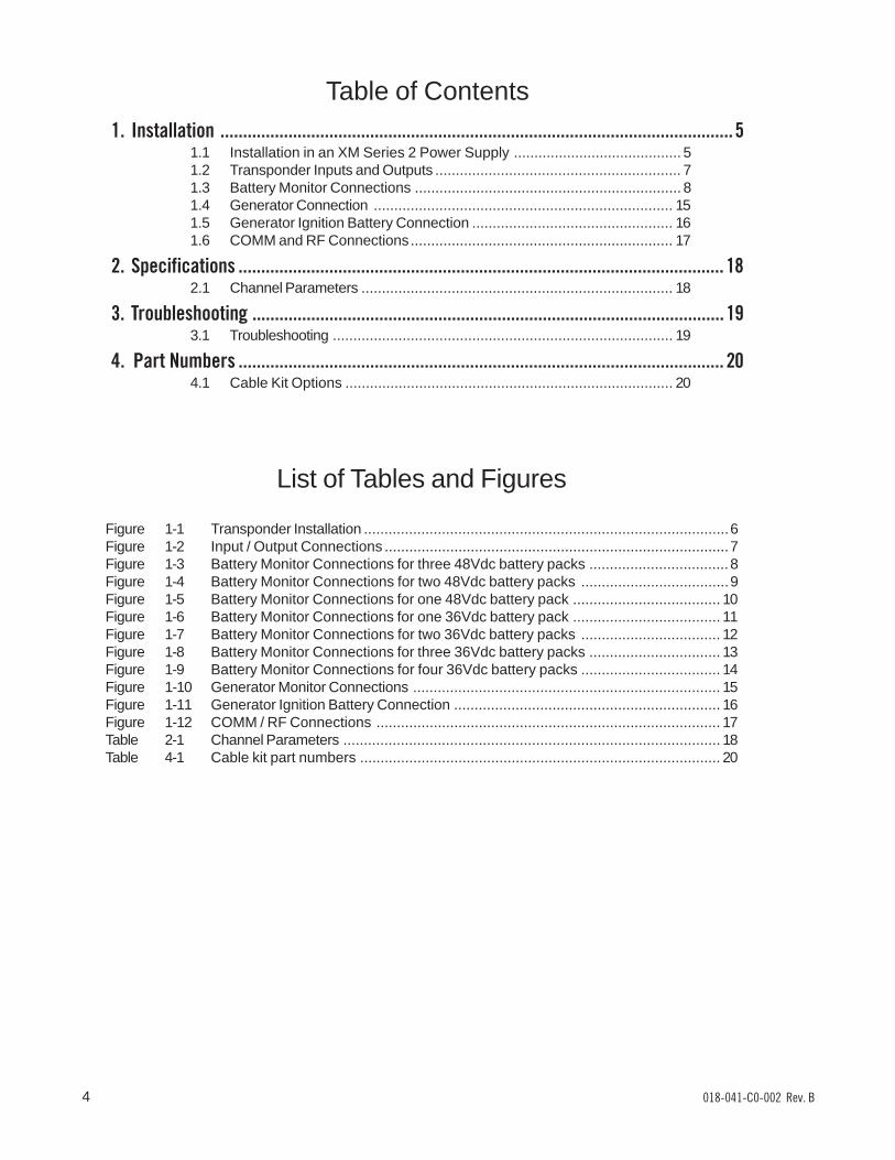
6. Slide the inverter module out far enough to unplugthe ribbon cable at the back of the inverter module(fig A). Disengage the two latches holding the pluginto the socket (fig. B), and remove the plug.
7. Slide the inverter module all of the way out of thepower supply.
8. Remove the blanking plate and USM2 (if installed)from the inverter module.
9. Install the USM2.5 (refer to USM2.5 installationmanual)
10. On the USM2.5, unplug the ribbon cable from J3,near the DIP Switch (fig. C).
11. Connect the other end of the ribbon cable to theconnector (JP2) at the top of the transponder(fig. C).
Disconnect here
Unlatch
J3
JP2
������
������
������
018-041-C0-002 Rev. B6
1. Installation
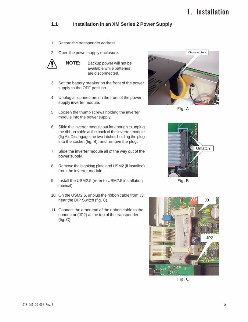
12. Using the two captive screws just behind the face plate, secure the transponderto the inverter module.
13. Verify that the 10 position jumper on the transponder is set to the correctbattery pack voltage.
14. Verify that the 8 position DIP Switch on the USM2.5 is set correctly. Refer to the USM2.5operators manual (Alpha p/n 704-683-B0).
15. Set the inverter module onto the guides, and side it 1 or 2 inches into the power supply.
16. Reconnect the ribbon cable to the inverter module, and latch the two retainingclips over the ribbon cable plug.
17. Slide the inverter module fully into the power supply, and tighten the thumbscrews. Set the BATTERY BREAKER to the ON position.
18. Verify after 10-30 seconds, the Smart Display on the power supply reads'OPERATION NORMAL'.
19. Download Alarm Profile from NetMentor to initiate appropriate mode of operation.
20. Verify that, after approx. 1 minute, the 'CPU' LED on the front of the transponderis blinking, if not, press the RESET button behind the hole next to the LEDs(see Fig. 1-2).
1.1 Installation in an XM Series 2 Power Supply, continued
Figure 1-1 Transponder Installation
8 Position DIPSwitch
10 PositionJumper
Captivescrew
Captivescrew
7018-041-C0-002 Rev. B
1. Installation
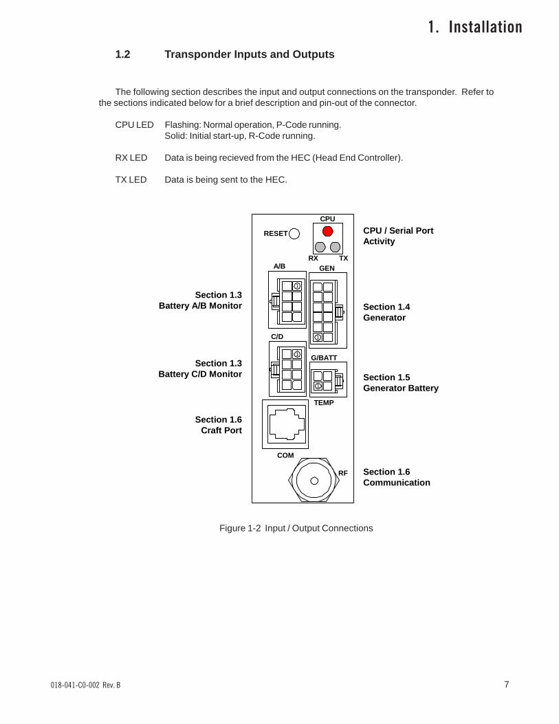
1.2 Transponder Inputs and Outputs
The following section describes the input and output connections on the transponder. Refer tothe sections indicated below for a brief description and pin-out of the connector.
CPU LED Flashing: Normal operation, P-Code running.Solid: Initial start-up, R-Code running.
RX LED Data is being recieved from the HEC (Head End Controller).
TX LED Data is being sent to the HEC.
RX TXGENA/B
C/D
G/BATT
TEMP
COM
RF
1
1
1
1
CPU
RESET
Section 1.3Battery A/B Monitor
Section 1.3Battery C/D Monitor
Section 1.6Craft Port
Section 1.4Generator
Section 1.5Generator Battery
Section 1.6Communication
CPU / Serial PortActivity
Figure 1-2 Input / Output Connections
018-041-C0-002 Rev. B8
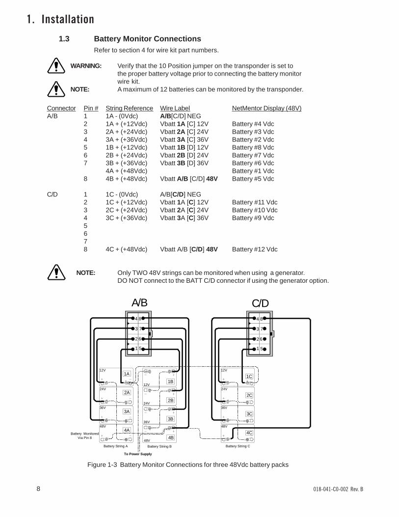
1.3 Battery Monitor Connections
1. Installation
Connector Pin # String Reference Wire Label NetMentor Display (48V)A/B 1 1A - (0Vdc) A/B[C/D] NEG
2 1A + (+12Vdc) Vbatt 1A [C] 12V Battery #4 Vdc3 2A + (+24Vdc) Vbatt 2A [C] 24V Battery #3 Vdc4 3A + (+36Vdc) Vbatt 3A [C] 36V Battery #2 Vdc5 1B + (+12Vdc) Vbatt 1B [D] 12V Battery #8 Vdc6 2B + (+24Vdc) Vbatt 2B [D] 24V Battery #7 Vdc7 3B + (+36Vdc) Vbatt 3B [D] 36V Battery #6 Vdc
4A + (+48Vdc) Battery #1 Vdc8 4B + (+48Vdc) Vbatt A/B [C/D] 48V Battery #5 Vdc
C/D 1 1C - (0Vdc) A/B[C/D] NEG2 1C + (+12Vdc) Vbatt 1A [C] 12V Battery #11 Vdc3 2C + (+24Vdc) Vbatt 2A [C] 24V Battery #10 Vdc4 3C + (+36Vdc) Vbatt 3A [C] 36V Battery #9 Vdc5678 4C + (+48Vdc) Vbatt A/B [C/D] 48V Battery #12 Vdc
NOTE: Only TWO 48V strings can be monitored when using a generator.DO NOT connect to the BATT C/D connector if using the generator option.
Figure 1-3 Battery Monitor Connections for three 48Vdc battery packs
A/B C/D
Refer to section 4 for wire kit part numbers.
WARNING: Verify that the 10 Position jumper on the transponder is set tothe proper battery voltage prior to connecting the battery monitorwire kit.
NOTE: A maximum of 12 batteries can be monitored by the transponder.
12V
24V
36V
48V
Battery String A Battery String B
12V
24V
36V
48V
Battery String C
12V
24V
36V
48V
1
2
3
4
5
6
7
8
1
2
3
4
5
6
7
8
Battery MonitoredVia Pin 8
1A
2A
3A
4A
1B
2B
3B
4B
1C
2C
3C
4C
To Power Supply
9018-041-C0-002 Rev. B
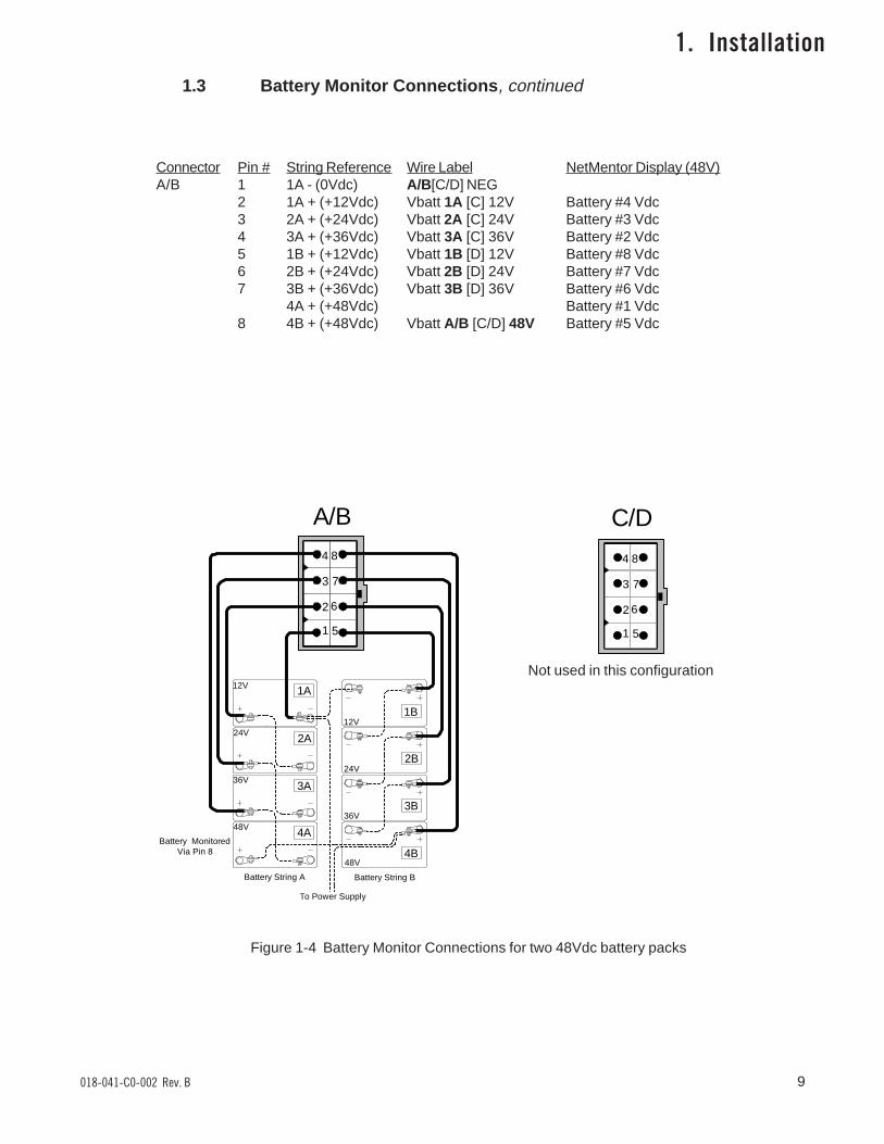
Connector Pin # String Reference Wire Label NetMentor Display (48V)A/B 1 1A - (0Vdc) A/B[C/D] NEG
2 1A + (+12Vdc) Vbatt 1A [C] 12V Battery #4 Vdc3 2A + (+24Vdc) Vbatt 2A [C] 24V Battery #3 Vdc4 3A + (+36Vdc) Vbatt 3A [C] 36V Battery #2 Vdc5 1B + (+12Vdc) Vbatt 1B [D] 12V Battery #8 Vdc6 2B + (+24Vdc) Vbatt 2B [D] 24V Battery #7 Vdc7 3B + (+36Vdc) Vbatt 3B [D] 36V Battery #6 Vdc
4A + (+48Vdc) Battery #1 Vdc8 4B + (+48Vdc) Vbatt A/B [C/D] 48V Battery #5 Vdc
1
2
3
4
5
6
7
8
1.3 Battery Monitor Connections, continued
Figure 1-4 Battery Monitor Connections for two 48Vdc battery packs
A/B C/D
1. Installation
Not used in this configuration
12V
24V
36V
48V
Battery String A Battery String B
12V
24V
36V
48V
1
2
3
4
5
6
7
8
Battery MonitoredVia Pin 8
1A
2A
3A
4A
1B
2B
3B
4B
To Power Supply
018-041-C0-002 Rev. B10
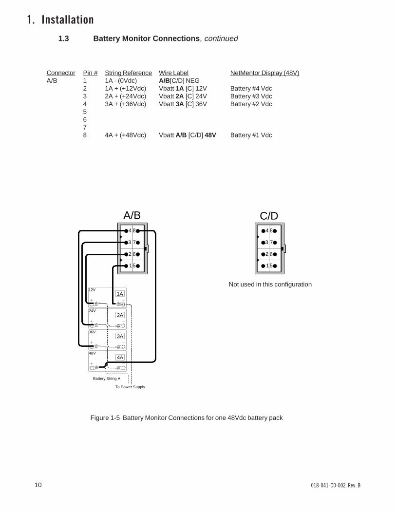
Connector Pin # String Reference Wire Label NetMentor Display (48V)A/B 1 1A - (0Vdc) A/B[C/D] NEG
2 1A + (+12Vdc) Vbatt 1A [C] 12V Battery #4 Vdc3 2A + (+24Vdc) Vbatt 2A [C] 24V Battery #3 Vdc4 3A + (+36Vdc) Vbatt 3A [C] 36V Battery #2 Vdc5678 4A + (+48Vdc) Vbatt A/B [C/D] 48V Battery #1 Vdc
1. Installation1.3 Battery Monitor Connections, continued
1
2
3
4 8
7
6
5
Battery String A
12V
24V
36V
48V
1
2
3
4 8
7
6
5
1A
2A
3A
4A
To Power Supply
A/B C/D
Figure 1-5 Battery Monitor Connections for one 48Vdc battery pack
Not used in this configuration
11018-041-C0-002 Rev. B
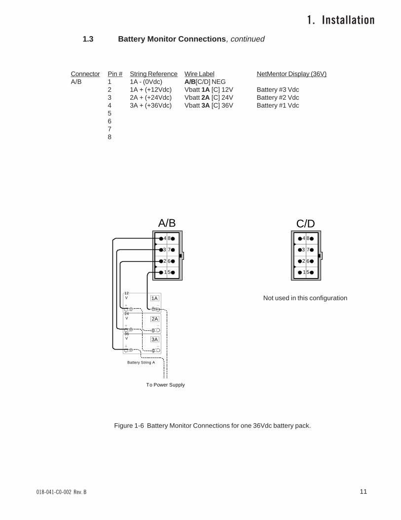
Connector Pin # String Reference Wire Label NetMentor Display (36V)A/B 1 1A - (0Vdc) A/B[C/D] NEG
2 1A + (+12Vdc) Vbatt 1A [C] 12V Battery #3 Vdc3 2A + (+24Vdc) Vbatt 2A [C] 24V Battery #2 Vdc4 3A + (+36Vdc) Vbatt 3A [C] 36V Battery #1 Vdc5678
1. Installation1.3 Battery Monitor Connections, continued
Figure 1-6 Battery Monitor Connections for one 36Vdc battery pack.
A/B C/D
1
2
3
4 8
7
6
5
Battery String A
12V
24V
36V
1
2
3
4 8
7
6
5
1A
2A
3A
To Power Supply
Not used in this configuration
018-041-C0-002 Rev. B12
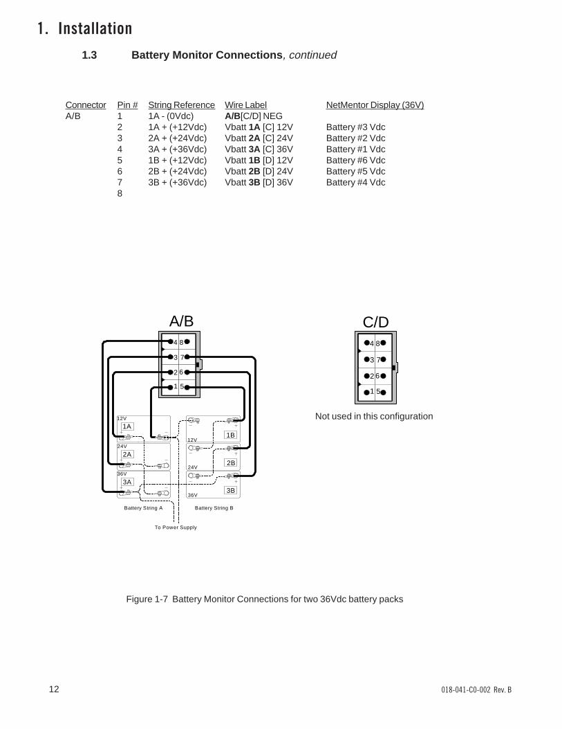
Connector Pin # String Reference Wire Label NetMentor Display (36V)A/B 1 1A - (0Vdc) A/B[C/D] NEG
2 1A + (+12Vdc) Vbatt 1A [C] 12V Battery #3 Vdc3 2A + (+24Vdc) Vbatt 2A [C] 24V Battery #2 Vdc4 3A + (+36Vdc) Vbatt 3A [C] 36V Battery #1 Vdc5 1B + (+12Vdc) Vbatt 1B [D] 12V Battery #6 Vdc6 2B + (+24Vdc) Vbatt 2B [D] 24V Battery #5 Vdc7 3B + (+36Vdc) Vbatt 3B [D] 36V Battery #4 Vdc8
1. Installation1.3 Battery Monitor Connections, continued
12V
24V
36V
12V
24V
36V
1
2
3
4
5
6
7
8
Battery String A Battery String B
1A
2A
3A
1B
2B
3B
To Power Supply
A/B C/D
1
2
3
4
5
6
7
8
Figure 1-7 Battery Monitor Connections for two 36Vdc battery packs
Not used in this configuration
13018-041-C0-002 Rev. B
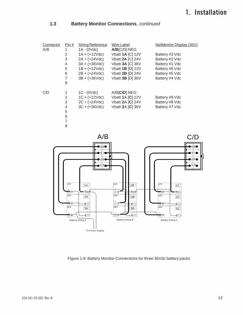
Connector Pin # String Reference Wire Label NetMentor Display (36V)A/B 1 1A - (0Vdc) A/B[C/D] NEG
2 1A + (+12Vdc) Vbatt 1A [C] 12V Battery #3 Vdc3 2A + (+24Vdc) Vbatt 2A [C] 24V Battery #2 Vdc4 3A + (+36Vdc) Vbatt 3A [C] 36V Battery #1 Vdc5 1B + (+12Vdc) Vbatt 1B [D] 12V Battery #6 Vdc6 2B + (+24Vdc) Vbatt 2B [D] 24V Battery #5 Vdc7 3B + (+36Vdc) Vbatt 3B [D] 36V Battery #4 Vdc8
C/D 1 1C - (0Vdc) A/B[C/D] NEG2 1C + (+12Vdc) Vbatt 1A [C] 12V Battery #9 Vdc3 2C + (+24Vdc) Vbatt 2A [C] 24V Battery #8 Vdc4 3C + (+36Vdc) Vbatt 3A [C] 36V Battery #7 Vdc5678
1. Installation1.3 Battery Monitor Connections, continued
Battery String A Battery String B
12V
24V
36V
12V
24V
36V
12V
24V
36V
Battery String C
1
2
3
4
5
6
7
8
1
2
3
4
5
6
7
8
1A
2A
3A
1B
2B
3B
1C
2C
3C
To Power Supply
Figure 1-8 Battery Monitor Connections for three 36Vdc battery packs
A/B C/D
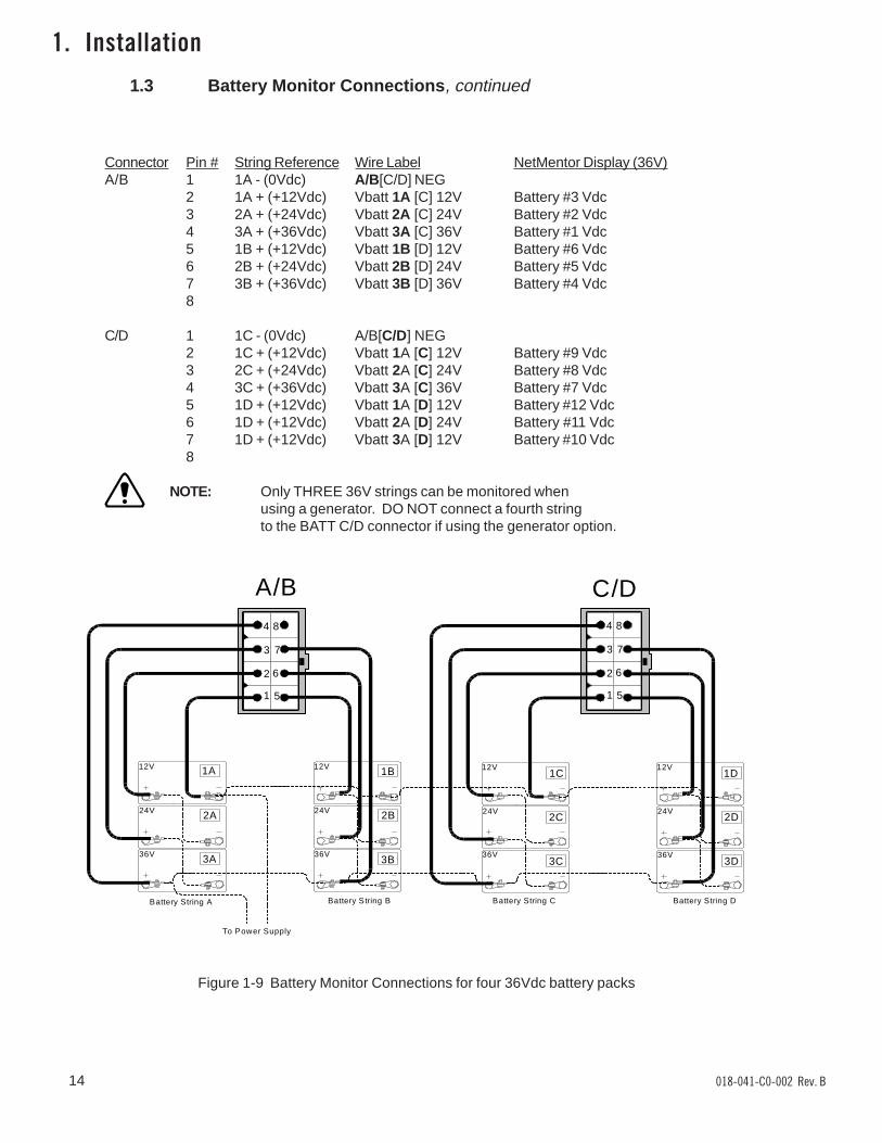
Connector Pin # String Reference Wire Label NetMentor Display (36V)A/B 1 1A - (0Vdc) A/B[C/D] NEG
2 1A + (+12Vdc) Vbatt 1A [C] 12V Battery #3 Vdc3 2A + (+24Vdc) Vbatt 2A [C] 24V Battery #2 Vdc4 3A + (+36Vdc) Vbatt 3A [C] 36V Battery #1 Vdc5 1B + (+12Vdc) Vbatt 1B [D] 12V Battery #6 Vdc6 2B + (+24Vdc) Vbatt 2B [D] 24V Battery #5 Vdc7 3B + (+36Vdc) Vbatt 3B [D] 36V Battery #4 Vdc8
C/D 1 1C - (0Vdc) A/B[C/D] NEG2 1C + (+12Vdc) Vbatt 1A [C] 12V Battery #9 Vdc3 2C + (+24Vdc) Vbatt 2A [C] 24V Battery #8 Vdc4 3C + (+36Vdc) Vbatt 3A [C] 36V Battery #7 Vdc5 1D + (+12Vdc) Vbatt 1A [D] 12V Battery #12 Vdc6 1D + (+12Vdc) Vbatt 2A [D] 24V Battery #11 Vdc7 1D + (+12Vdc) Vbatt 3A [D] 12V Battery #10 Vdc8
NOTE: Only THREE 36V strings can be monitored whenusing a generator. DO NOT connect a fourth stringto the BATT C/D connector if using the generator option.
Battery String A Battery String B
12V
24V
36V
12V
24V
36V
12V
24V
36V
12V
24V
36V
Battery String C Battery String D
1
2
3
4
5
6
7
8
1
2
3
4
5
6
7
8
1A
2A
3A
1B
2B
3B
1C
2C
3C
1D
2D
3D
To Power Supply
1.3 Battery Monitor Connections, continued
Figure 1-9 Battery Monitor Connections for four 36Vdc battery packs
A/B C/D
1. Installation
14 018-041-C0-002 Rev. B
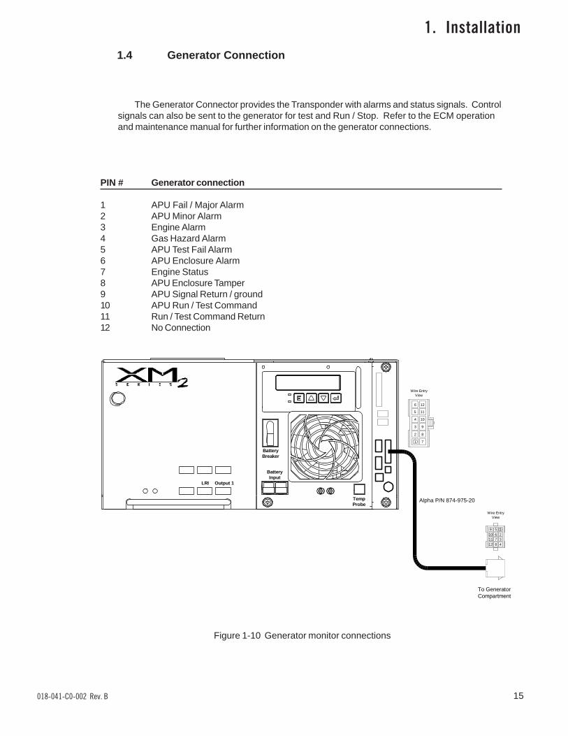
1.4 Generator Connection
The Generator Connector provides the Transponder with alarms and status signals. Controlsignals can also be sent to the generator for test and Run / Stop. Refer to the ECM operationand maintenance manual for further information on the generator connections.
PIN # Generator connection
1 APU Fail / Major Alarm2 APU Minor Alarm3 Engine Alarm4 Gas Hazard Alarm5 APU Test Fail Alarm6 APU Enclosure Alarm7 Engine Status8 APU Enclosure Tamper9 APU Signal Return / ground10 APU Run / Test Command11 Run / Test Command Return12 No Connection
1. Installation
Figure 1-10 Generator monitor connections
Alpha P/N 874-975-20
Output 1LRI
BatteryInput
TempProbe
BatteryBreaker
To GeneratorCompartment
159261037114812
Wire EntryView
6 12
5 11
4 10
3 9
2 8
1 7
Wire EntryView
15018-041-C0-002 Rev. B
018-041-C0-002 Rev. B16
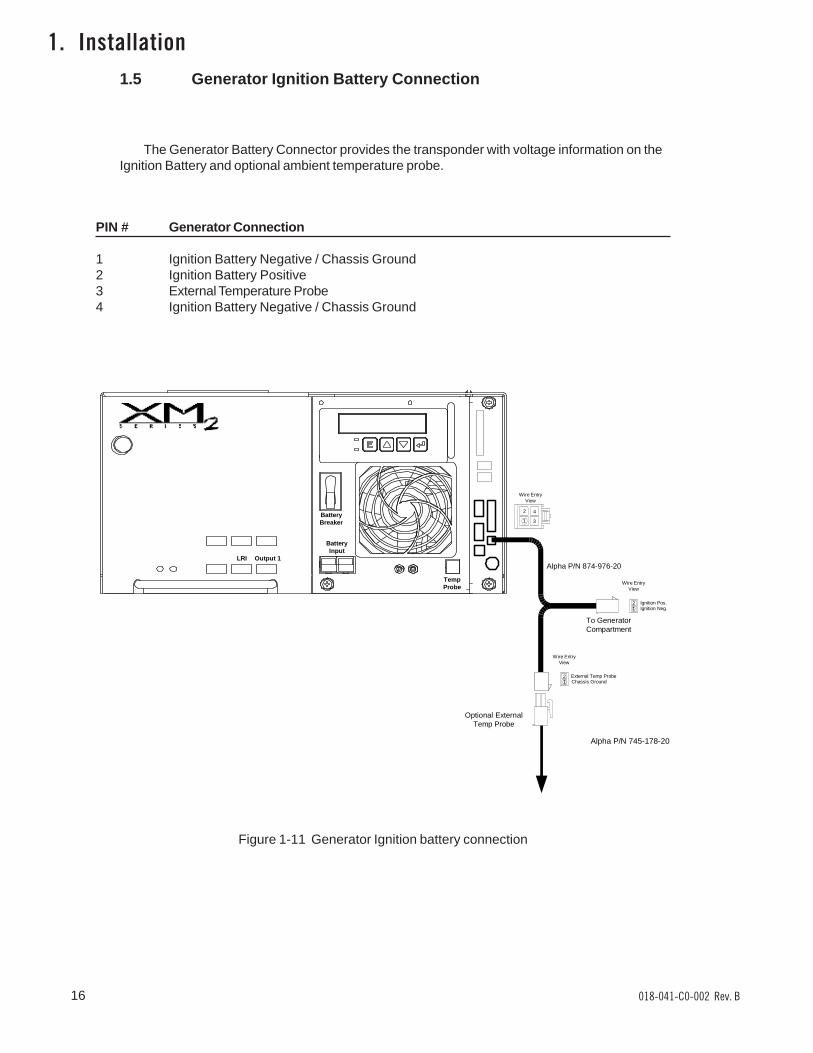
1. Installation1.5 Generator Ignition Battery Connection
The Generator Battery Connector provides the transponder with voltage information on theIgnition Battery and optional ambient temperature probe.
PIN # Generator Connection
1 Ignition Battery Negative / Chassis Ground2 Ignition Battery Positive3 External Temperature Probe4 Ignition Battery Negative / Chassis Ground
Figure 1-11 Generator Ignition battery connection
Alpha P/N 745-178-20
Output 1LRI
BatteryInput
TempProbe
BatteryBreaker
To GeneratorCompartment
12 Ignition Pos.
Ignition Neg.
Wire EntryView
1
2
3
4
Wire EntryView
External Temp ProbeChassis Ground
Wire EntryView
Optional ExternalTemp Probe
Alpha P/N 874-976-20
12
17018-041-C0-002 Rev. B
1. Installation
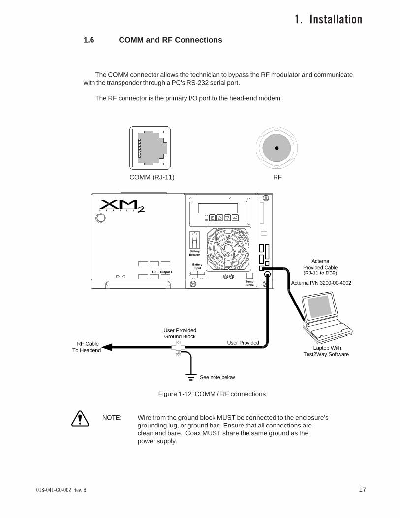
1.6 COMM and RF Connections
The COMM connector allows the technician to bypass the RF modulator and communicatewith the transponder through a PC's RS-232 serial port.
The RF connector is the primary I/O port to the head-end modem.
COMM (RJ-11) RF
Figure 1-12 COMM / RF connections
NOTE: Wire from the ground block MUST be connected to the enclosure'sgrounding lug, or ground bar. Ensure that all connections areclean and bare. Coax MUST share the same ground as thepower supply.
Output 1LRI
BatteryInput
TempProbe
BatteryBreaker
Laptop WithTest2Way Software
RF CableTo Headend
ActernaProvided Cable
User Provided
User ProvidedGround Block
See note below
(RJ-11 to DB9)
Acterna P/N 3200-00-4002
018-041-C0-002 Rev. B18
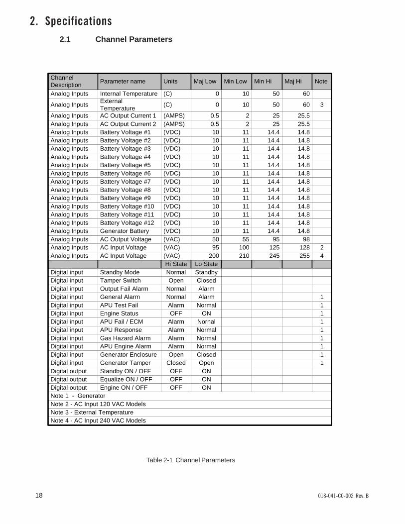
2. Specifications2.1 Channel Parameters
Table 2-1 Channel Parameters
Hi State Lo State
ChannelDescription
Parameter name Units Maj Low Min Low Min Hi Maj Hi Note
Analog Inputs Internal Temperature (C) 0 10 50 60
Analog InputsExternalTemperature
(C) 0 10 50 60 3
Analog Inputs AC Output Current 1 (AMPS) 0.5 2 25 25.5Analog Inputs AC Output Current 2 (AMPS) 0.5 2 25 25.5Analog Inputs Battery Voltage #1 (VDC) 10 11 14.4 14.8Analog Inputs Battery Voltage #2 (VDC) 10 11 14.4 14.8Analog Inputs Battery Voltage #3 (VDC) 10 11 14.4 14.8Analog Inputs Battery Voltage #4 (VDC) 10 11 14.4 14.8Analog Inputs Battery Voltage #5 (VDC) 10 11 14.4 14.8Analog Inputs Battery Voltage #6 (VDC) 10 11 14.4 14.8Analog Inputs Battery Voltage #7 (VDC) 10 11 14.4 14.8Analog Inputs Battery Voltage #8 (VDC) 10 11 14.4 14.8Analog Inputs Battery Voltage #9 (VDC) 10 11 14.4 14.8Analog Inputs Battery Voltage #10 (VDC) 10 11 14.4 14.8Analog Inputs Battery Voltage #11 (VDC) 10 11 14.4 14.8Analog Inputs Battery Voltage #12 (VDC) 10 11 14.4 14.8
Analog Inputs AC Output Voltage (VAC) 50 55 95 98Analog Inputs AC Input Voltage (VAC) 95 100 125 128 2
Digital input Standby Mode Normal StandbyDigital input Tamper Switch Open ClosedDigital input Output Fail Alarm Normal AlarmDigital input General Alarm Normal Alarm 1Digital input APU Test Fail Alarm Normal 1Digital input Engine Status OFF ON 1Digital input APU Fail / ECM Alarm Nornal 1Digital input APU Response Alarm Normal 1Digital input Gas Hazard Alarm Alarm Normal 1Digital input APU Engine Alarm Alarm Normal 1Digital input Generator Enclosure Open Closed 1Digital input Generator Tamper Closed Open 1Digital output Standby ON / OFF OFF ONDigital output Equalize ON / OFF OFF ONDigital output Engine ON / OFF OFF ONNote 1 - GeneratorNote 2 - AC Input 120 VAC ModelsNote 3 - External Temperature
Analog Inputs AC Input Voltage (VAC) 200 210 245 255 4
Analog Inputs Generator Battery (VDC) 10 11 14.4 14.8
Note 4 - AC Input 240 VAC Models
19018-041-C0-002 Rev. B
3.1 Testing and Troubleshooting
3. Troubleshooting
Testing
All testing shall be performed via Acterna's NetMentor and Test2way software. Refer tosoftware manufacturer's instructions.
Troubleshooting
Problem: Missing parts or shipping damage.Solution: Contact Alpha Technologies at:
Alpha Technologies, Inc.3767 Alpha WayBellingham, WA. 98226360-647-2360
Problem: Unable to communicate with transponder.Solution: Check port assignments, cables, and RPS name / port.
Problem: Incorrect device type selected when adding unit.Solution: Check the device type in the Device Configuration screen (NetMentor).
Problem: Incorrect address.Solution: Verify address in the Devive Configuration screen (NetMentor).
Problem: Incorrect controller frequencies.Solution Verify frequencies on the HEC port configuration screen.
Problem: Incorrect signal level.Solution: Verify forward and return signals are within Acterna specifications.
Padding may have to be added or removed.
Problem: Unable to communicate with NetMentor.Solution: Verify that the transponder is not in 'R' mode. Use laptop computer
running 'Test2Way' to verify what code is running.
If the CPU LED is on steady, unit is in 'R-code', if the LED is flashing, unitis in 'P-code' (normal operation).
018-041-C0-002 Rev. B20
�������������
��� ����� ��������������������� �������� ������!�"���� ��#$%& �%'���������( �������� ������!�"���� ��#$%& �%'���������� �������� ������!�"���� ��#$%& �)'���������� �������� ������!�"���� ��#$%& �)'���������� �������� ������!�"���� ��#��& �%'���������( �������� ������!�"���� ��#��& �%'���������* �������� ������!�"���� ��#��& �)'���������� �������� ������!�"���� ��#��& �)'���������$ +#���������������� ������!�"���� �%'���������� +#���������������� ������!�"���� �$*'����)�*��( +����,������-���.��������/����0���������������)�%��( +����,������-���/�������������!���������
������������������������������������ ��
��� ����� ���������������))���( ��������! �1��������2� ���� �/��3+#� �4"5��*��*�(�*��( ��������! �1��������2� ���� �$�"6� �/��3+#� �4"5��*
����������������������������������
��� ����� �������������*��$���( ��� ��7��-� ��8��"�2! �/�������� �75"�
4. Part Numbers
4.1 Cable Kit Options
Table 4-1 Cable kit part numbers
��������������
��� ����� �������������*������( ����������"�������� ��#$%& �83�.���/����0����*��)���$ ����������"�������� ��#$%& �83�$*'�+#����*��)���� ����������"�������� �$#$%& �83��#$*'�+#����*��)���� ����������"�������� �$#$%& ���9�%' ���9�)'��*���(��( ����������"�������� ��#$%& �83��#$*'�+#����*������( ����������"�������� ��#$%& ���9�%' ���9�)'��*���%��( ����������"�������� ��#��& �83�.���/����0����*��)���( ����������"�������� ��#��& �83�$*'�+#����*��)���� ����������"�������� �$#��& �83��#$*'�+#����*��)���( ����������"�������� �$#��& ���9�%' ���9�)'��*���*��( ������.��������7�-����������


Due to continuing product improvements, Alpha reserves the right to change specifications without notice.Copyright © 2002 by Alpha Technologies, Inc. All rights reserved. Alpha is a registered trademark of Alpha Technologies. 018-041-C0-002 Rev. B.
CorporateAlpha Technologies3767 Alpha WayBellingham, WA 98226USATel: (360) 647-2360Fax: (360) 671-4936Web: www.alpha.com
Alpha Technologies Ltd.4084 McConnell CourtBurnaby, BC, V5A 3N7CANADATel: (604) 430-1476Fax: (604) 430-8908
Alpha TechnologiesEurope Ltd.Cartel Business EstateEdinburgh WayHarlow, Essex CM20 2TTUNITED KINGDOMTel: +44-1279-422110Fax: +44-1279-423355
Alpha TechnologiesHansastrasse 8D-91126 SchwabachGERMANYTel: +49-9122-79889-0Fax: +49-9122-79889-21
Alphatec339 St. Andrews StreetSuite 101Andrea ChambersLimassol, CyprusCYPRUSTel: +357-25-375675Fax: +357-25-359595
Alpha TechnologiesUnit R5-R7 Regents Park EstateCorner Park Rd and Prince’s Rd EastRegents Park, NSW 2143AUSTRALIATel: +61-2-9722-3320Fax: +61-2-9722-3321
Powerwww.alpha.com Protecting The Power in Communications.


![SDH Pocket Guide - Acterna[1]](https://img.pdfslide.us/doc/110x75/5529110d5503464d2e8b45f8/sdh-pocket-guide-acterna1.jpg)