Embed Size (px)
Citation preview
DETECTING HARDWARE-ASSISTED HYPERVISOR ROOTKITS WITHIN NESTED VIRTUALIZED ENVIRONMENTS
THESIS
Daniel B. Morabito, Captain, USAF
AFIT/GCO/ENG/12-20
DEPARTMENT OF THE AIR FORCE AIR UNIVERSITY
AIR FORCE INSTITUTE OF TECHNOLOGY
Wright-Patterson Air Force Base, Ohio
APPROVED FOR PUBLIC RELEASE; DISTRIBUTION UNLIMITED

The views expressed in this thesis are those of the author and do not reflect the official policy or position of the United States Air Force, Department of Defense, or the United States Government. This material is declared a work of the U.S. Government and is not subject to copyright protection in the United States.
AFIT/GCO/ENG/12-20
DETECTING HARDWARE-ASSISTED HYPERVISOR ROOTKITS WITHIN NESTED VIRTUALIZED ENVIRONMENTS
THESIS
Presented to the Faculty
Department of Electrical and Computer Engineering
Graduate School of Engineering and Management
Air Force Institute of Technology
Air University
Air Education and Training Command
In Partial Fulfillment of the Requirements for the
Degree of Master of Science
Daniel B. Morabito, M.S. Leadership, B.S. Computer Science
Captain, USAF
June 2012
APPROVED FOR PUBLIC RELEASE; DISTRIBUTION UNLIMITED.
AFIT/GCO/ENG/12-20
DETECTING HARDWARE-ASSISTED HYPERVISOR ROOTKITS WITHIN NESTED VIRTUALIZED ENVIRONMENTS
Daniel B. Morabito, M.S. Leadership, B.S. Computer Science
Captain, USAF
iv
AFIT/GCO/ENG/12-20
Abstract
Virtual machine introspection (VMI) is intended to provide a secure and trusted
platform from which forensic information is gathered about the true behavior of malware
within a guest. However, it is possible for malware to escape a guest into the host and for
hypervisor rootkits, such as BluePill, to stealthily transition a native OS into a virtualized
environment. This suggests that VMI scenarios provide an environment where it is
possible for malware to escape the guest, obtain privileged access to the processor, insert
a thin hypervisor rootkit beneath the host, and gain near-perfect visibility into the guest
and host by transitioning them into a nested virtualized environment. This research
examines the effectiveness of selected detection mechanisms against hardware-assisted
virtualization rootkits (HAV-R) within a nested virtualized environment. It presents the
design, implementation, analysis, and evaluation of a hypervisor rootkit detection system
which exploits both processor and translation lookaside buffer-based mechanisms to
detect hypervisor rootkits within a variety of nested virtualized systems. It evaluates the
effects of different types of virtualization on hypervisor rootkit detection and explores the
effectiveness of a likely countermeasure which is tested for its ability to obfuscate the
existence of a hardware-assisted hypervisor rootkit.
Experiments are performed in a laboratory environment consisting of a notional
VMI system which is implemented using four different hypervisor configurations
representing three different virtualization types. Detection measurements are taken on a
non-subverted VMI system and compared to those taken after one of two notional
v
HAV-Rs (BluePill and ESXi) is installed on the VMI system resulting in a subverted
VMI (SVMI) system. A third set of readings are taken on the SVMI system after an
obfuscation agent is installed within the guest. When analyzed using the Wilcoxon rank
sum test for non-parametric data, a p-value of < 2.2e-16 is obtained for all VMI to SVMI
comparisons. This rejects the null hypothesis that the population distributions are
identical and provides convincing evidence that the HAV-Rs are detectable in all SVMI
scenarios, regardless of hypervisor type. Furthermore, it indicates that the selected
detection techniques are effective at detection of HAV-R and that the type of
virtualization implemented in a VMI system has minimal to no effect on HAV-R
detection. Finally, the results indicate that in-guest obfuscation does not significantly
obfuscate the existence of HAV-R.
vi
Acknowledgments
My sincerest thanks and appreciation go to my wife whose patience, support, and
love were a constant source of inspiration and energy during this research. You are an
amazing woman, wife, and mother to our children. Next, my advisor Dr. Barry E.
Mullins who never unduly constrained my work and let me see just how far the
virtualization rabbit hole really goes. Also, Professor Cynthia C. Fry of Baylor
University. All students have those teachers who leave a particularly lasting impression;
thank you for your faith and guidance. Finally, special thanks go to Herr Hagen Fritsch
who contributed the original driver framework which was used to develop HyperScan.
Ich bin Ihnen sehr dankbar. I am very grateful for your help.
Daniel B. Morabito
vii
Table of Contents
Page
Abstract .............................................................................................................................. iv
Acknowledgments.............................................................................................................. vi
Table of Contents .............................................................................................................. vii
List of Figures .................................................................................................................... xi
List of Tables .................................................................................................................... xx
I. Introduction .................................................................................................................... 1
1.1. Goals ....................................................................................................................... 3
1.2. Assumptions and Limitations .................................................................................. 3
1.3. Research Contributions ........................................................................................... 5
1.4. Thesis Organization ................................................................................................ 5
II. Background .................................................................................................................... 7
2.1. General Virtualization Concepts ............................................................................. 7
2.1.1. The Roots of Virtualization ........................................................................... 7
2.1.2. Virtualization Definition & Theory ............................................................. 10
2.1.3. Types of Virtualization ................................................................................ 15
2.1.4. Nested Virtualization ................................................................................... 24
2.1.5. Virtual Machine Introspection ..................................................................... 25
2.1.6. Benefits of Virtualization ............................................................................ 27
2.2. Hypervisors (Virtual Machine Managers) ............................................................ 30
2.2.1. QEMU 0.9.0 ................................................................................................ 30
2.2.2. VirtualBox 4.1.10 ........................................................................................ 30
2.2.3. VMware Workstation 8 ............................................................................... 31
2.2.4. VMware ESXi 5.0 ....................................................................................... 31
2.3. Subverting the Hypervisor: Detect, Evade, and Escape ........................................ 32
2.3.1. VM Detection .............................................................................................. 33
2.3.2. Hypervisor Evasion ..................................................................................... 43
2.3.3. Escaping a VM ............................................................................................ 46
2.4. Subverting the Host: Hardware-assisted Virtualization Rootkits ......................... 47
2.4.1. BluePill ........................................................................................................ 48
viii
2.4.2. SubVirt ......................................................................................................... 50
2.4.3. Characteristics of HAV-R ........................................................................... 51
2.5. HAV-R Detection.................................................................................................. 51
2.5.1. Execution Profiling ...................................................................................... 52
2.5.2. Translation Lookaside Buffer Profiling ....................................................... 56
2.6. Conclusion ............................................................................................................ 58
III. Methodology ............................................................................................................... 60
3.1. Problem Definition ................................................................................................ 60
3.1.1. Goals and Hypothesis .................................................................................. 61
3.1.2. Approach ..................................................................................................... 61
3.2. HyperScan Software Development ....................................................................... 63
3.3. Cloaker Software Development ............................................................................ 65
3.4. System Boundaries ................................................................................................ 66
3.5. System Services .................................................................................................... 66
3.6. Workload ............................................................................................................... 67
3.7. Performance Metrics ............................................................................................. 68
3.8. System Parameters ................................................................................................ 68
3.8.1. Hardware ..................................................................................................... 68
3.8.2. Trusted (Native) OS ..................................................................................... 69
3.8.3. Guest OS ...................................................................................................... 69
3.8.4. CPU HAV Setting ....................................................................................... 69
3.9. Factors ................................................................................................................... 69
3.9.1. Hypervisor ................................................................................................... 70
3.9.2. HAV-R ......................................................................................................... 70
3.9.3. Guest Obfuscation Agent ............................................................................. 71
3.10. Evaluation Technique.......................................................................................... 71
3.11. Experimental Design ........................................................................................... 74
3.12. Methodology Summary ....................................................................................... 75
IV. Analysis ...................................................................................................................... 76
4.1. Exploratory Data Analysis .................................................................................... 77
4.2. Detection of HAV-R within Nested Virtualized Environments ........................... 84
4.3. Effects of Obfuscation (Cloaker) .......................................................................... 87
ix
4.4. The Effect of Different Virtualization Types on HAV-R Detection..................... 94
4.5. Summary ............................................................................................................... 96
V. Conclusions ................................................................................................................. 98
5.1. Results ................................................................................................................... 98
5.2. Future Work ........................................................................................................ 100
5.3. Concluding Remarks ........................................................................................... 101
Appendix A. Experimentation ....................................................................................... 103
A-1. Setup the Non-Subverted VMI Scenario and Install the HyperScan Files ........ 103
A-2. Create Test Certificates and Sign Drivers within the Host and Guest OS ......... 104
A-3. Non-Subverted VMI Scenario Experiments ...................................................... 106
A-4. Subverted VMI Scenario Experiments .............................................................. 110
A-5. Subverted VMI Scenario with Guest Obfuscation Experiments ....................... 111
Appendix B. Windows Driver Kit Installation & Configuration .................................... 113
B-1. Install Windows Driver Kit (WDK) ................................................................... 113
B-2. Enable Test-signing and Disable Integrity Checks ............................................ 114
Appendix C. VMware Workstation 8 and Windows 7 Setup ........................................ 115
C-1. Download and Install VMware Workstation 8 .................................................. 115
C-2. Create and Configure the Windows 7 Installation ............................................. 115
Appendix D. VirtualBox Installation and Windows 7 Setup ......................................... 127
D-1. Download and Install VirtualBox ...................................................................... 127
D-2. Create and Configure the Virtual Machine ........................................................ 128
Appendix E. QEMU Setup and Windows 7 Installation ............................................... 136
E-1. Setup QEMU ...................................................................................................... 136
E-2. Create Blank Disk Image and Install Windows 7 .............................................. 136
Appendix F. BluePill Installation on Windows Vista 64 ............................................... 141
F-1. Enable Test-Signing, Disable Integrity Checks, and Install WinDK ................. 141
F-2. Build the BluePill Driver .................................................................................... 141
F-3. Create a Test Certificate ..................................................................................... 142
F-4. Install the Test Certificate in the Trusted Root Certification Store .................... 144
F-5. Embedded Sign the BluePill newbp.sys Driver ................................................. 146
F-6. Start the BluePill Driver ..................................................................................... 148
x
Appendix G. ESX Installation ....................................................................................... 150
G-1. Download VMware ESXi 5.0.0 on Host Machine ............................................ 150
G-2. Configure the ESXi Host ................................................................................... 150
G-3. Create the Virtual Machine ................................................................................ 155
G-4. Append the OS.vmx File to Enable Nested Virtualization ................................ 170
G-5. Install the Guest OS (64-bit Windows Vista Business) ..................................... 172
Appendix H. Statistical Analysis ................................................................................... 174
xi
List of Figures
Figure Page
1. IBM System/370 Model 138 [IBM11]. .................................................................. 9
2. Virtualization Architecture ................................................................................... 12
3. The x86 Protection Ring Architecture .................................................................. 13
4. Multiple VMs Sharing a Single Host Machine Adapted from [Dod10] ............... 16
5. Multiple VMs Sharing Two Host Machines ......................................................... 16
6. OS Virtualization Adapted from [Dod10]. ........................................................... 18
7. Emulation .............................................................................................................. 19
8. Paravirtualization Adapted from [Dod10] ............................................................ 20
9. Full Virtualization and Hardware-assisted Virtualization .................................... 22
10. Intel VT-x Virtualization State Diagram .............................................................. 24
11. ESXi Hypervisor with vSphere Client ................................................................. 32
12. Fingerprinting Windows XP Using msinfo32 ...................................................... 34
13. Fingerprinting Unix Using dmidecode –t system ................................................. 35
14. Checking the OUI of a Unix machine................................................................... 36
15. The OUI Search Results........................................................................................ 37
16. Machine Code for Comm Channel Detection Adapted from [Fer08] .................. 38
17. BluePill Installation and Operation Adapted from [RuT07] ................................ 49
18. VMI Scenario Transitioned to Subverted VMI Scenario ..................................... 62
19. HyperScan Data Collection Process ..................................................................... 64
20. HyperScan Operation with Default and Manual Settings ..................................... 64
21. Cloaker Operation ................................................................................................. 65
xii
22. The System Under Test (SUT) ............................................................................. 66
23. HAV-R DS Possible Outcomes ............................................................................ 67
24. Chart of Factor Combinations (Virtualization Scenarios) .................................... 74
25. Untransformed SMPCOUNT Data ....................................................................... 80
26. Log Transformed SMPCOUNT Data ................................................................... 80
27. Untransformed TIMING Data .............................................................................. 81
28. Log Transformed TIMING Data .......................................................................... 81
29. Untransformed TLBHIT Data............................................................................... 82
30. Log Transformed TLBHIT Data ........................................................................... 82
31. Comparison of Median SMPCOUNT Data with 95% CI ..................................... 86
32. Comparison of Median TIMING Data with 95% CI ............................................ 86
33. Comparison of Median TLBHIT Data with 95% CI ............................................ 87
34. Comparison of SMPCOUNT VMI vs. SVMI with GO Medians with 95% CI ... 89
35. Comparison of TIMING VMI vs. SVMI with GO Medians with 95% CI ........... 89
36. Comparison of TIMING VMI vs. SVMI with GO Medians with 95% CI ........... 90
37. Comparison of BluePill Median SVMI to SVMI with GO SMPCOUNT Data ... 92
38. Comparison of BluePill Median SVMI to SVMI with GO TIMING Data .......... 92
39. Comparison of BluePill Median SVMI to SVMI with GO TLBHIT Data........... 92
40. Comparison of ESXi Median SVMI to SVMI with GO SMPCOUNT Data ....... 93
41. Comparison of ESXi Median SVMI to SVMI with GO TIMING Data ............... 93
42. Comparison of ESXi Median SVMI to SVMI with GO TLBHIT Data ............... 94
43. Difference Between Medians (SVMI-VMI), SMPCOUNT with 95% CI ............ 95
44. Difference Between Medians (SVMI-VMI), TIMING with 95% CI ................... 95
xiii
45. Difference Between Medians (SVMI-VMI), TLBHIT with 95% CI ................... 96
46. Configuring the Host and Guest Machine: File Placement ................................ 104
47. Execution of create_test_cert.bat ........................................................................ 105
48. Execution of sign_drivers.bat ............................................................................. 105
49. Using InstDrv to Install detector.sys ................................................................... 106
50. SVM Detectors Loaded Message........................................................................ 107
51. HyperScan Example............................................................................................ 108
52. Performance Manger ........................................................................................... 108
53. Using InstDrv to Install dbgclient.sys ................................................................. 110
54. Using InstDrv to Install newbp.sys ..................................................................... 110
55. Cloaker Execution ............................................................................................... 111
56. Performance Manager ......................................................................................... 112
57. WinDK Installation Settings ............................................................................... 113
58. Enabling Test-Signing and Disabling Integrity Checks ...................................... 114
59. Select “Create a New Virtual Machine” ............................................................. 115
60. Select “Custom” and Click “Next” ..................................................................... 116
61. Select “Workstation 8.0” and Click “Next” ........................................................ 116
62. Check Install From Location and Click “Next” .................................................. 117
63. Fill In and Click “Next” ...................................................................................... 117
64. Name the Virtual Machine .................................................................................. 118
65. Processor Configuration...................................................................................... 119
66. Memory Configuration ....................................................................................... 119
67. Network Configuration ....................................................................................... 120
xiv
68. I/O Controller Configuration .............................................................................. 120
69. Create a New Virtual Disk .................................................................................. 121
70. Select a Disk Type .............................................................................................. 121
71. Specify Disk Capacity......................................................................................... 122
72. Specify the Disk File ........................................................................................... 122
73. Select “Customize Hardware” ............................................................................ 123
74. Full Virtualization using Binary Translation Configuration ............................... 124
75. Hardware-assisted Full Virtualization Configuarion .......................................... 125
76. Select “Finish” to Complete the Virtual Machine .............................................. 126
77. Custom Setup ...................................................................................................... 127
78. Create a New Virtual Machine ........................................................................... 128
79. Memory Allocation ............................................................................................. 129
80. Virtual Hard Disk ................................................................................................ 129
81. Select File Type .................................................................................................. 130
82. Select Drive Allocation Type .............................................................................. 130
83. Allocate Virtual Disk Location and Size ............................................................ 131
84. Virtual Disk Summary Window ......................................................................... 132
85. Double Click Win7 to Start the Virtual Machine ............................................... 133
86. Welcome to First Run Wizard ............................................................................ 133
87. Windows Boot Manager Unexpected Error ........................................................ 134
88. Hardware Acceleration Error Message ............................................................... 134
89. Enable PAE/NX .................................................................................................. 135
90. Create the Blank Disk Image .............................................................................. 137
xv
91. Boot the Virtual Machine for Installation of Windows 7 ................................... 137
92. Clone Hard Disk ................................................................................................. 139
93. Boot the Windows 7 Virtual Machine ................................................................ 140
94. BluePill Build Example ...................................................................................... 142
95. Test Certificate Creation, makecert Command ................................................... 143
96. Certificate Manager ............................................................................................ 144
97. Add Test Certificate to Trusted Root Store ........................................................ 145
98. Certificate Manager ............................................................................................ 145
99. Trusted Root Certification Authority Folder ...................................................... 146
100. Sign the BluePill Driver ...................................................................................... 147
101. Signtool Verification ........................................................................................... 147
102. Installing the BluePill dbgclient.sys Driver ........................................................ 148
103. Installing the BluePill newbp.sys Driver ............................................................ 148
104. bpknock.exe Before and After Installation of BluePill ....................................... 149
105. DebugView Showing Successful BluePill Installation ....................................... 149
106. Log Into the vSphere Client ................................................................................ 151
107. Enter the vSphere License Key ........................................................................... 152
108. Enable SSH on the host machine ........................................................................ 153
109. SSH into the Host Machine................................................................................. 153
110. Open the /etc/vmware/config File for Editing .................................................... 154
111. Add vhv.allow = “TRUE” to the config file ....................................................... 154
112. Select Custom Configuration .............................................................................. 155
113. Enter the Name of the VM .................................................................................. 156
xvi
114. Storage Settings .................................................................................................. 157
115. Select Virtual Machine Version .......................................................................... 158
116. Select Guest Operating System ........................................................................... 159
117. CPU Settings ....................................................................................................... 160
118. Memory Settings ................................................................................................. 161
119. Network Settings ................................................................................................. 162
120. SCSI Controller Settings ..................................................................................... 163
121. Create a New Virtual Disk .................................................................................. 164
122. Disk Configuration Settings ................................................................................ 165
123. Advanced Options Left at Default Settings ........................................................ 166
124. Select the Edit Virtual Machine Settings Before Completion Option ................ 167
125. Edit the Hardware Tab ........................................................................................ 168
126. Edit the CPU/MMU Virtualization Tab .............................................................. 169
127. Locating the Data Store ...................................................................................... 170
128. Download the OS.vmx Folder ............................................................................ 171
129. Append the .vmx Folder ..................................................................................... 171
130. Power on the Virtual Machine ............................................................................ 172
131. Select the Console Tab to View the Installation ................................................. 173
132. Windows Installation Screen .............................................................................. 173
133. QQ Plot and Density Plot: QEMU_VMI_SMPCOUNT .................................... 174
134. QQ Plot and Density Plot: QEMU_SVMI_BP_SMPCOUNT .......................... 174
135. QQ Plot and Density Plot: QEMU_SVMI_BP_SMPCOUNT ........................... 175
136. QQ Plot and Density Plot: QEMU_SVMI_BP_SMPCOUNT ........................... 175
xvii
137. QQ Plot and Density Plot: VBOXHAV_VMI_SMPCOUNT ............................ 175
138. QQ Plot and Density Plot: VBOXHAV_SVMI_BP_SMPCOUNT ................... 176
139. QQ Plot and Density Plot: VBOX_SVMI_ESX_SMPCOUNT ......................... 176
140. QQ Plot and Density Plot: VBOXHAV_SVMI_ESX_GO_SMPCOUNT ........ 176
141. QQ Plot and Density Plot: VMWAREBT_VMI_SMPCOUNT ......................... 177
142. QQ Plot and Density Plot: VMWARE_SVMI_BP_SMPCOUNT ..................... 177
143. QQ Plot and Density Plot: VMWAREBT_SVMI_BP_GO_SMPCOUNT ........ 177
144. QQ Plot and Density Plot: VMWAREBT_SVMI_ESX_SMPCOUNT ............. 178
145. QQ Plot and Density Plot: VMWAREHAV_VMI_SMPCOUNT ..................... 178
146. QQ Plot and Density Plot: VMWAREHAV_SVMI_BP_SMPCOUNT ............ 178
147. QQ Plot and Density Plot: VMWAREHAV_SVMI_ESX_SMPCOUNT ......... 179
148. QQ Plot and Density Plot: VMWAREHAV_SVMI_ESX_GO_SMPCOUNT.. 179
149. QQ Plot and Density Plot: VMWAREBT_SVMI_ESX_GO_SMPCOUNT ..... 179
150. QQ Plot and Density Plot: QEMU_VMI_TIMING............................................ 180
151. QQ Plot and Density Plot: QEMU_SVMI_BP_TIMING .................................. 180
152. QQ Plot and Density Plot: QEMU_SVMI_BP_GO_TIMING ........................... 180
153. QQ Plot and Density Plot: QEMU_SVMI_ESX_TIMING ................................ 181
154. QQ Plot and Density Plot: VBOX_VMI_TIMING ............................................ 181
155. QQ Plot and Density Plot: VBOXHAV_SVMI_BP_TIMING .......................... 181
156. QQ Plot and Density Plot: VBOX_SVMI_ESX_TIMING ................................ 182
157. QQ Plot and Density Plot: VBOXHAV_SVMI_ESX_GO_TIMING ................ 182
158. QQ Plot and Density Plot: VMWAREBT_VMI_TIMING ................................ 182
xviii
159. QQ Plot and Density Plot: VMWAREBT_SVMI_BP_TIMING ....................... 183
160. QQ Plot and Density Plot: VMWAREBT_SVMI_BP_TIMING ....................... 183
161. QQ Plot and Density Plot: VMWAREBT_SVMI_ESX_TIMING .................... 183
162. QQ Plot and Density Plot: VMWAREBT_SVMI_ESX_GO_TIMING ............ 184
163. QQ Plot and Density Plot: VMWAREBT_SVMI_ESX_GO_TIMING ............ 184
164. QQ Plot and Density Plot:VMWAREBT_SVMI_ESX_GO_TIMING ............. 184
165. QQ Plot and Density Plot: VMWAREHAV_SVMI_ESX_TIMING ................. 185
166. QQ Plot and Density Plot: VMWAREHAV_SVMI_ESX_TIMING ................. 185
167. QQ Plot and Density Plot: QEMU_VMI_TLBHIT ............................................ 185
168. QQ Plot and Density Plot: QEMU_SVMI_BP_TLBHIT ................................... 186
169. QQ Plot and Density Plot: QEMU_SVMI_BP_GO_TLBHIT ........................... 186
170. QQ Plot and Density Plot: QEMU_SVMI_ESX_TLBHIT ............................... 186
171. QQ Plot and Density Plot: VBOXHAV_VMI_TLBHIT .................................... 187
172. QQ Plot and Density Plot: VBOXHAV_SVMI_BP_TLBHIT .......................... 187
173. QQ Plot and Density Plot: VBOXHAV_SVMI_ESX_TLBHIT ........................ 187
174. QQ Plot and Density Plot: VBOXHAV_SVMI_ESX_GO_TLBHIT ................ 188
175. QQ Plot and Density Plot: VMWAREBT_VMI_TLBHIT ................................ 188
176. QQ Plot and Density Plot: VMWAREBT_SVMI_BP_TLBHIT ....................... 188
177. QQ Plot and Density Plot: VMWAREBT_SVMI_BP_GO_TLBHIT ............... 189
178. QQ Plot and Density Plot: VMWAREBT_SVMI_ESX_TLBHIT .................... 189
179. QQ Plot and Density Plot: VMWAREBT_SVMI_ESX_GO_TLBHIT ............. 189
180. QQ Plot and Density Plot: VMWAREHAV_VMI_TLBHIT ............................. 190

xix
181. QQ Plot and Density Plot: VMWAREHAV_SVMI_BP_TLBHIT.................... 190
182. QQ Plot and Density Plot: VMWAREHAV_SVMI_ESX_TLBHIT ................. 190
183. QQ Plot and Density Plot: VMWAREHAV_SVMI_ESX_GO_TLBHIT ......... 191
xx
List of Tables
Table Page
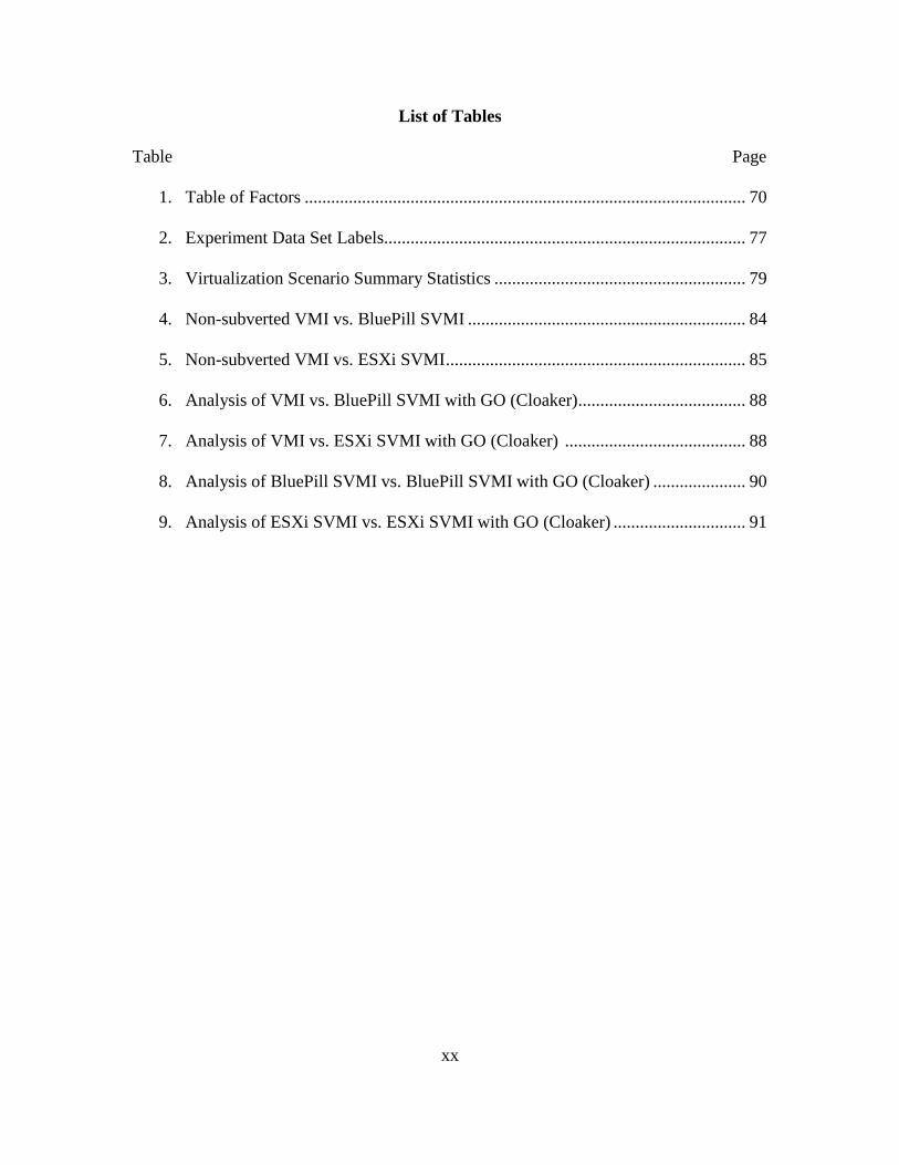
1. Table of Factors .................................................................................................... 70
2. Experiment Data Set Labels.................................................................................. 77
3. Virtualization Scenario Summary Statistics ......................................................... 79
4. Non-subverted VMI vs. BluePill SVMI ............................................................... 84
5. Non-subverted VMI vs. ESXi SVMI .................................................................... 85
6. Analysis of VMI vs. BluePill SVMI with GO (Cloaker) ...................................... 88
7. Analysis of VMI vs. ESXi SVMI with GO (Cloaker) ......................................... 88
8. Analysis of BluePill SVMI vs. BluePill SVMI with GO (Cloaker) ..................... 90
9. Analysis of ESXi SVMI vs. ESXi SVMI with GO (Cloaker) .............................. 91
1
DETECTING HARDWARE-ASSISTED HYPERVISOR ROOTKITS WITHIN
NESTED VIRTUALIZED ENVIRONMENTS
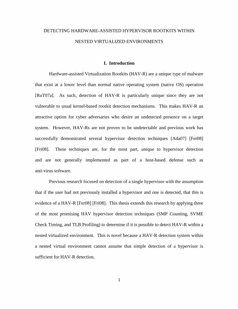
I. Introduction
Hardware-assisted Virtualization Rootkits (HAV-R) are a unique type of malware
that exist at a lower level than normal native operating system (native OS) operation
[RuT07a]. As such, detection of HAV-R is particularly unique since they are not
vulnerable to usual kernel-based rootkit detection mechanisms. This makes HAV-R an
attractive option for cyber adversaries who desire an undetected presence on a target
system. However, HAV-Rs are not proven to be undetectable and previous work has
successfully demonstrated several hypervisor detection techniques [Ada07] [Fer08]
[Fri08]. These techniques are, for the most part, unique to hypervisor detection
and are not generally implemented as part of a host-based defense such as
anti-virus software.
Previous research focused on detection of a single hypervisor with the assumption
that if the user had not previously installed a hypervisor and one is detected, that this is
evidence of a HAV-R [Fer08] [Fri08]. This thesis extends this research by applying three
of the most promising HAV hypervisor detection techniques (SMP Counting, SVME
Check Timing, and TLB Profiling) to determine if it is possible to detect HAV-R within a
nested virtualized environment. This is novel because a HAV-R detection system within
a nested virtual environment cannot assume that simple detection of a hypervisor is
sufficient for HAV-R detection.
2
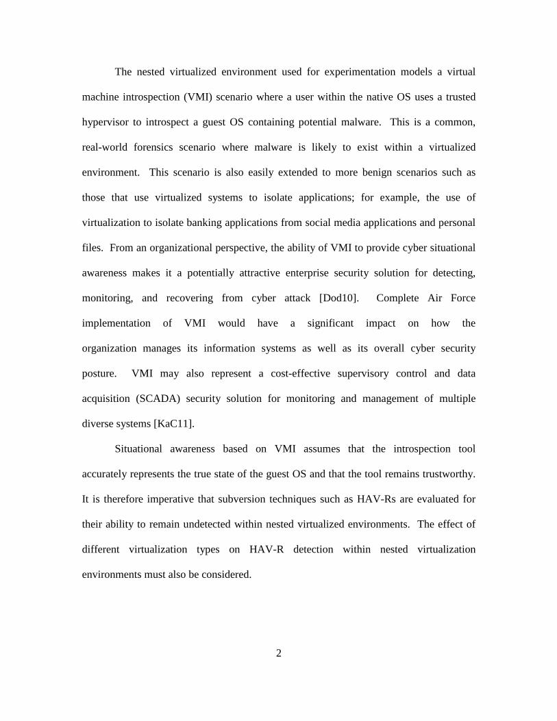
The nested virtualized environment used for experimentation models a virtual
machine introspection (VMI) scenario where a user within the native OS uses a trusted
hypervisor to introspect a guest OS containing potential malware. This is a common,
real-world forensics scenario where malware is likely to exist within a virtualized
environment. This scenario is also easily extended to more benign scenarios such as
those that use virtualized systems to isolate applications; for example, the use of
virtualization to isolate banking applications from social media applications and personal
files. From an organizational perspective, the ability of VMI to provide cyber situational
awareness makes it a potentially attractive enterprise security solution for detecting,
monitoring, and recovering from cyber attack [Dod10]. Complete Air Force
implementation of VMI would have a significant impact on how the
organization manages its information systems as well as its overall cyber security
posture. VMI may also represent a cost-effective supervisory control and data
acquisition (SCADA) security solution for monitoring and management of multiple
diverse systems [KaC11].
Situational awareness based on VMI assumes that the introspection tool
accurately represents the true state of the guest OS and that the tool remains trustworthy.
It is therefore imperative that subversion techniques such as HAV-Rs are evaluated for
their ability to remain undetected within nested virtualized environments. The effect of
different virtualization types on HAV-R detection within nested virtualization
environments must also be considered.
3
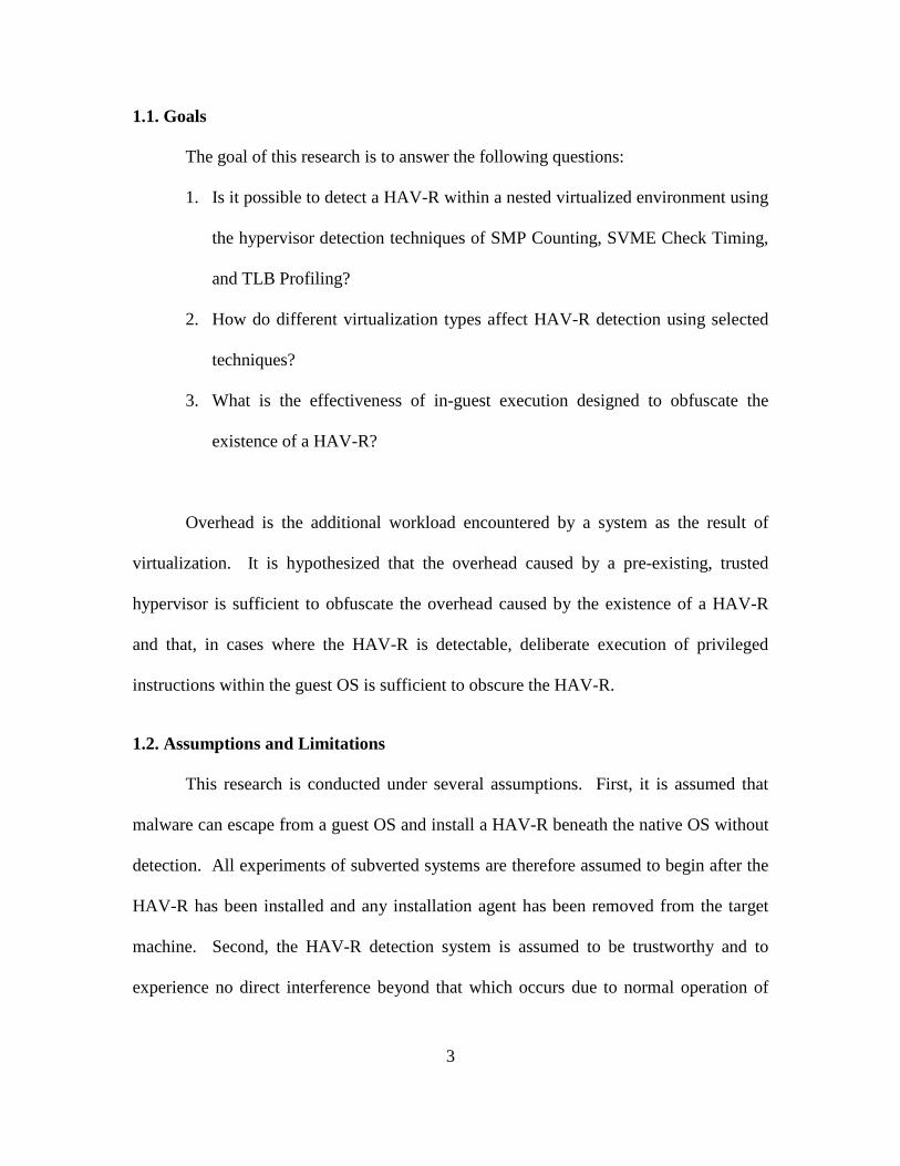
1.1. Goals
The goal of this research is to answer the following questions:
1. Is it possible to detect a HAV-R within a nested virtualized environment using
the hypervisor detection techniques of SMP Counting, SVME Check Timing,
and TLB Profiling?
2. How do different virtualization types affect HAV-R detection using selected
techniques?
3. What is the effectiveness of in-guest execution designed to obfuscate the
existence of a HAV-R?
Overhead is the additional workload encountered by a system as the result of
virtualization. It is hypothesized that the overhead caused by a pre-existing, trusted
hypervisor is sufficient to obfuscate the overhead caused by the existence of a HAV-R
and that, in cases where the HAV-R is detectable, deliberate execution of privileged
instructions within the guest OS is sufficient to obscure the HAV-R.
1.2. Assumptions and Limitations
This research is conducted under several assumptions. First, it is assumed that
malware can escape from a guest OS and install a HAV-R beneath the native OS without
detection. All experiments of subverted systems are therefore assumed to begin after the
HAV-R has been installed and any installation agent has been removed from the target
machine. Second, the HAV-R detection system is assumed to be trustworthy and to
experience no direct interference beyond that which occurs due to normal operation of
4
the native OS. Third, the detection system is assumed to provide the statistical analysis
required for HAV-R detection. As part of the research effort, detection software is
developed to collect detection-oriented data however, the statistical analysis is performed
manually. It is left to future work to integrate the statistical analysis tools into the
detection software.
Research evaluation is limited to 64-bit Windows Vista Business as the native OS
and 64-bit Windows 7 Professional as the guest OS. BluePill, one of the two HAV-Rs
used for experimentation, is designed for exclusive use with 64-bit Windows Vista which
constrains the native OS to this platform. For the guest OS, 64-bit Windows 7
Professional is selected since it represents a current and commonly used OS.
This research is also limited in terms of the breadth of HAV-Rs examined. Of the
two examples used for this research, BluePill is a true but purely academic example of a
HAV-R that was created in 2006 and therefore may not be considered a state-of-the-art
implementation of HAV-R. The second example, ESXi, is not a true HAV-R but is
chosen as a simulated HAV-R - a thin hypervisor with HAV-R-like characteristics. While
it is likely that other real-world implementations of HAV-R exist, they are difficult to
locate, likely since this area of virtualization-based attack is relatively new and is
seemingly not yet widely exploited. The two HAV-Rs selected are a best-effort
representation of likely real-world HAV-Rs.
Finally, this research is limited to the AMD-V architecture as implemented by the
Athlon 64 X2 7750 Black Edition Dual Core 2.70 GHz processor used during testing.
While it is likely that the detection techniques work just as well for other architectures,
this cannot be assumed.
5
1.3. Research Contributions
This research evaluates selected HAV-R detection techniques and compares the
effects of different virtualization types on the detection of HAV-R within nested
virtualized environments. This is an unexplored area of virtualization research which is
particularly applicable to VMI environments used for forensics research. Additionally,
existing hypervisor detection techniques are extended and consolidated into two software
tools, HyperScan and Cloaker, which perform HAV-R detection and obfuscation
respectively. These detection techniques, applied in the novel form of HyperScan, are
used to perform the requisite data collection and analysis for this thesis and establish a
previously non-existent foundation for automated detection of HAV-Rs.
1.4. Thesis Organization
This chapter presents an introduction to the research effort including thesis goals,
assumptions, limitations, and research contributions.
Chapter II provides background information on general virtualization concepts, a
description of the particular hypervisors used for this thesis, an examination of hypervisor
and host subversion techniques as they specifically relate to virtualization, and discussion
of the HAV-R detection techniques with special emphasis on those used for this research.
Chapter III presents the methodology used in this research to include system
inputs, outputs, parameters, and a description of the factors and their levels. It also
provides information on the software developed for this research effort.
Chapter IV presents an analysis of the results gathered by the HAV-R detection
system. These are interpreted using statistical analysis and reveal the effectiveness of the
6
detection techniques, the effectiveness of the obfuscation tool, and the effect of different
virtualization types on HAV-R detection.
Chapter V presents a summary of the conclusions drawn from the analysis
performed in Chapter IV and recommends future work.
Various appendices are included that detail how to reproduce the virtualized
environments and experimentation conducted as part of this research effort.
Additionally, statistical figures which are not included in Chapter IV due to size
constraints are included in Appendix H for reference.
7
II. Background
This chapter provides a survey of virtualization concepts as well as offensive and
defensive virtualization paradigms. The particular hypervisors, hypervisor rootkits, and
detection techniques used for this research are discussed as well as general techniques for
hypervisor and host subversion.
2.1. General Virtualization Concepts
2.1.1. The Roots of Virtualization
Virtualization’s resurgence over the past decade as an attractive option for
efficient use of server and computer resources may create the impression that
virtualization is a new technology [Gol08]. In fact, virtualization concepts and
applications have existed for at least fifty years [Cre81] and can be traced back to a desire
that is as old as computing itself; to do more with less and to most efficiently use the
tools that are available.
The initial concepts of virtualization originated in the early 1960s from the
requirement to more efficiently use scarce and expensive computational resources
[Cre81]. Computers during this time existed almost exclusively within the realms of
military and academic research and were in such high demand that using them efficiently
was a primary and constant concern [Cor63] [Cre81]. This led to intense interest in
devices that could execute more than just a single program at a time and the
corresponding development of machines which were capable of handling the execution of
multiple programs simultaneously through the use of time-sharing and process
scheduling. Time-sharing is the rapid time-division multiplexing of a central processor
8
unit among the jobs of several simultaneous users [CoV65]. The result was a
transformation from computers which could handle only a single process from beginning
to end, to machines capable of handling multiple simultaneous processes from multiple
simultaneous users.
One of the earliest examples of this transformation was the result of efforts by
Massachusetts Institute of Technology (MIT) and International Business Machines (IBM)
in the early 1970s and was called the Virtual Machine/370 Time-Sharing System
(VM/370), originally called the pseudo-machine time-sharing system. This VM
consisted of three separate systems; a Control Program, a Remote Spooling and
Communications Subsystem, and a Conversational Monitor System. The Control
Program and Remote Spooling and Communications Subsystem served as what is now
referred to as a hypervisor, or virtual machine monitor (VMM). These systems were
responsible for managing time-sharing and process scheduling while abstracting the
underlying physical system in such a way that each user was presented with what
appeared to be their own singularly dedicated system; their own VM. The
Conversational Monitor System served as the guest operating system (guest OS) through
which multiple users were able to simultaneously interact with the system [Cre81].
These basic concepts of a hypervisor and one or more guest OS’s which share a physical
architecture form the basic model for modern virtual machines.
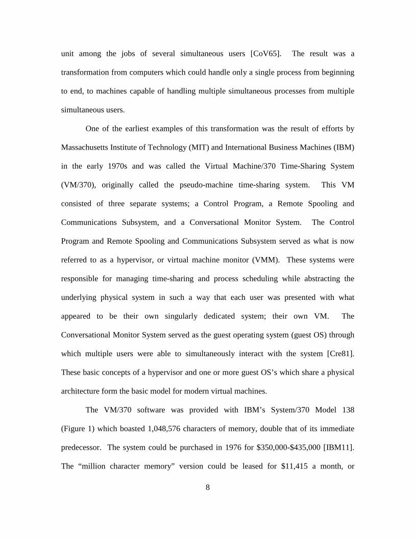
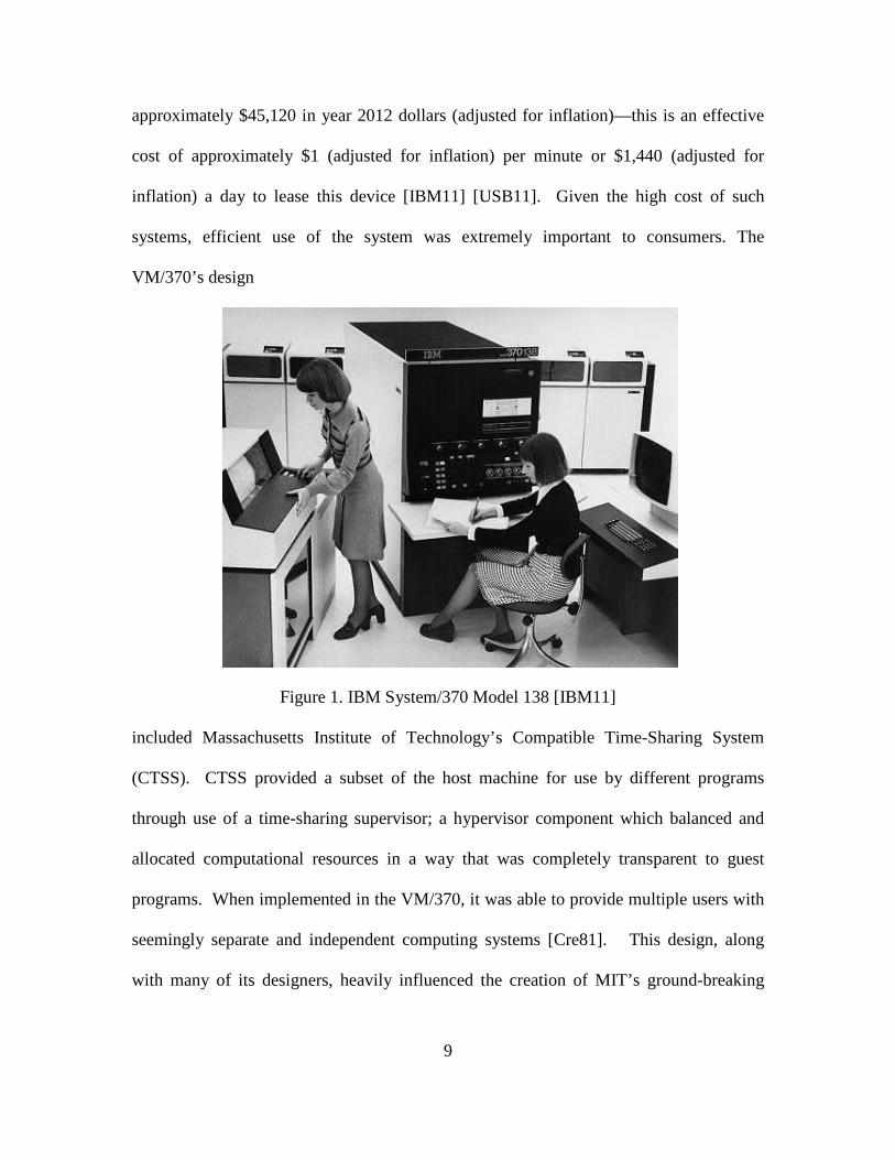
The VM/370 software was provided with IBM’s System/370 Model 138
(Figure 1) which boasted 1,048,576 characters of memory, double that of its immediate
predecessor. The system could be purchased in 1976 for $350,000-$435,000 [IBM11].
The “million character memory” version could be leased for $11,415 a month, or
9
approximately $45,120 in year 2012 dollars (adjusted for inflation)—this is an effective
cost of approximately $1 (adjusted for inflation) per minute or $1,440 (adjusted for
inflation) a day to lease this device [IBM11] [USB11]. Given the high cost of such
systems, efficient use of the system was extremely important to consumers. The
VM/370’s design
Figure 1. IBM System/370 Model 138 [IBM11] included Massachusetts Institute of Technology’s Compatible Time-Sharing System
(CTSS). CTSS provided a subset of the host machine for use by different programs
through use of a time-sharing supervisor; a hypervisor component which balanced and
allocated computational resources in a way that was completely transparent to guest
programs. When implemented in the VM/370, it was able to provide multiple users with
seemingly separate and independent computing systems [Cre81]. This design, along
with many of its designers, heavily influenced the creation of MIT’s ground-breaking
10
time-sharing operating system called “Multiplexed Information and Computing Service”
or MULTICS [Cre81]. MULTICS’ use of time sharing and ring-based access control,
built upon the ideas expressed in the VM/370 design, went on to influence UNIX and, in
turn, much of the modern computer functionality experienced today [Bis02].
Throughout the 1980s, computer technology advanced rapidly and the cost of
hardware declined, consequently reducing interest in the efficiencies offered by
virtualization. Then, in the 1990s, researchers at Stanford University took a renewed
interest in virtualization as a tool to implement massively parallel processing machines
with the goal of building increasingly powerful computers through the use of distributed
computing [RoG05]. Ironically, the proliferation of computing machines caused by the
lower hardware costs of the 1980s and early 1990s sparked renewed interest in finding
ways to more efficiently use the combined resources of these disparate systems and
instigated a resurgence of virtualization over the last decade [RoG05].
2.1.2. Virtualization Definition & Theory
Virtualization can be considered an abstraction of computer resources [JML10]
and described as “an efficient, isolated duplicate of [a] real machine” [PoG74]. A more
precise definition, as it specifically relates to virtual machines, describes virtualization as
a technique by which the physical resources of one or more host machines are abstracted,
managed, and shared to one or more guest OS’s in such a way that the guest OS’s
perform as if they are interacting directly and independently with those physical
resources [Bis02]. In this sense, “virtual” is different from “reality” only within the
formal world [JML10]; within the computer world, which itself exists as a mathematical
model and an abstraction of the “real” world, a virtual environment is perceived exactly
11
the same as that of a real environment, regardless of any formal differences in the
underlying mechanisms.
One of the first attempts to formerly model the concept of virtualization identified
the following three essential characteristics for virtualized architectures [PoG74]:
• Equivalency – The effect of virtualization must be such that the guest OS
is provided an environment essentially equivalent to the environment experienced
when the guest OS is running directly on the hardware.
• Efficiency – Virtualization must achieve the performance of the
virtualized hardware with minimal efficiency loss.
• Resource Control – Access to “real” resources must be managed by an
arbitration agent (the hypervisor) which ensures that (1) it is impossible for a
guest OS program to access any resource that is not explicitly allocated to it, and
(2) the hypervisor can interrupt and regain control of resources which it has
previously allocated to the guest OS.
Practically, these characteristics are achieved through use of an architecture consisting of
“real” underlying hardware (the host machine), a virtual environment consisting of
virtualized hardware (the VM), a management/arbitration agent (hypervisor) responsible
for resource control, and a hosted guest OS (Figure 2).
12
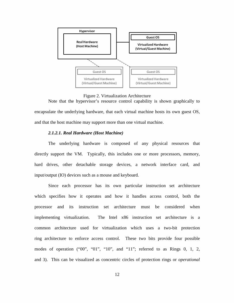
Figure 2. Virtualization Architecture Note that the hypervisor’s resource control capability is shown graphically to
encapsulate the underlying hardware, that each virtual machine hosts its own guest OS,
and that the host machine may support more than one virtual machine.
2.1.2.1. Real Hardware (Host Machine)
The underlying hardware is composed of any physical resources that
directly support the VM. Typically, this includes one or more processors, memory,
hard drives, other detachable storage devices, a network interface card, and
input/output (IO) devices such as a mouse and keyboard.
Since each processor has its own particular instruction set architecture
which specifies how it operates and how it handles access control, both the
processor and its instruction set architecture must be considered when
implementing virtualization. The Intel x86 instruction set architecture is a
common architecture used for virtualization which uses a two-bit protection
ring architecture to enforce access control. These two bits provide four possible
modes of operation (“00”, “01”, “10”, and “11”; referred to as Rings 0, 1, 2,
and 3). This can be visualized as concentric circles of protection rings or operational

13
modes where the innermost ring, Ring 0, has the most privileges, and the
outermost ring, Ring 3, has the least (Figure 3).
Figure 3. The x86 Protection Ring Architecture
This model enforces security by delineating modes of operation which limit operations
performed at lower privilege levels from performing actions reserved for operations
performing at higher privilege levels. This serves to isolate higher privilege processes,
such as kernel-level processes (Ring 0) from interference from lower privilege processes.
This separation is critical since the kernel is responsible for process management, file
access, security, and memory management within the OS [HoB05]. In practical use,
only Ring 0 (Kernel-mode) and Ring 3 (User-mode) are used by most OS’s.
Since the innermost ring, Ring 0, belongs to the kernel, exceptions must be made
for virtualization where the hypervisor must have the highest privilege level. This results
in a situation where the hypervisor is considered to operate at Ring -1 (minus one), the
kernel at Ring 0, and the user at Ring 3. The notional existence of a Ring -1 is referred to
as Ring Compression.
14
Some hardware is specifically designed to support virtualization, although
software-only virtualization is also common. Examples of hardware designed to support
virtualization include AMD Virtualization (AMD-V) and Intel’s Virtualization
Technology for the IA-32 architecture (VT-x), which both provide x86 instruction
extensions that can be used by the hypervisor for improved efficiency and security
[AdA07]. This is further discussed in Section 2.1.3.4.
2.1.2.2. Hypervisor
The hypervisor, also referred to as a “virtual machine manager” (VMM),
abstracts, manages, and shares the underlying physical architecture with one or more
guest OSs by presenting them with a set of virtual interfaces which constitute a virtual
machine [NSL06]. Since the resources of the underlying physical layer are abstracted by
the hypervisor, the hypervisor has complete control over how those resources are
allocated to the guest OSs. It can allocate as many or as few of the resources as its
configuration settings and the physical limitations of the system allow. It is even possible
to share the physical resources of different physical machines in such a way as to have
them provided to a VM as a virtual, single, and unified physical layer [TrH09].
The hypervisor’s functionality is similar to how an OS manages the state of each
of its processes. Control is maintained by trapping (pausing execution and passing
control to the hypervisor) whenever a privileged instruction is executed by the guest OS.
This transfer of control within the processor is called a context switch. The hypervisor
services the privileged instruction, providing the illusion that the instruction is executed
directly on the hardware, and passes control back to the guest OS [Bis02]. There are
configurations which, due to the hypervisor’s ability to intercept all interesting events
15
before they reach actual hardware, make the hypervisor more privileged then the host OS.
In such configurations, the hypervisor is considered an enhanced privileged host and may
be described as running at Ring -1 [RoG05] [Fer08]. The hypervisor uses various
techniques to manage and present resources to the guest OS. Several of these techniques
are covered in Section 2.1.3.
2.1.2.3. Virtual Machine
The virtual machine consists of the set of interfaces which simulate hardware and
are supplied by the hypervisor to the guest OS.
2.1.2.4. Guest Operating Systems
Guest OSs run independently of each other and interact only with allocated parts
of the underlying physical layer which comprise the virtual machine. Since the
hypervisor provides these parts as simulated hardware interfaces, the guest OSs usually
execute as if they are on their own stand-alone hardware, unaware that they exist as a VM
and are sharing resources with other guest OSs.
2.1.3. Types of Virtualization
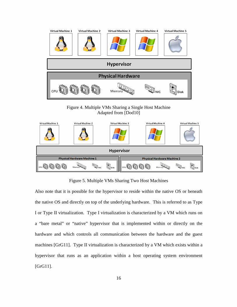
Two notional virtualization configurations are shown in Figures 4 and 5. Figure 4
depicts multiple VMs supporting a variety of OSs and running on a single host. Figure 5
also depicts multiple VMs supporting a variety of OSs but in this case, the hypervisor
utilizes the resources of a distributed physical architecture consisting of multiple physical
machines. Note that the abstraction of the physical layer presented by the hypervisor to
the guest OSs makes it seem as though each VM is running directly on its own dedicated
physical hardware.
16
Figure 4. Multiple VMs Sharing a Single Host Machine Adapted from [Dod10]
Figure 5. Multiple VMs Sharing Two Host Machines Also note that it is possible for the hypervisor to reside within the native OS or beneath
the native OS and directly on top of the underlying hardware. This is referred to as Type
I or Type II virtualization. Type I virtualization is characterized by a VM which runs on
a “bare metal” or “native” hypervisor that is implemented within or directly on the
hardware and which controls all communication between the hardware and the guest
machines [GrG11]. Type II virtualization is characterized by a VM which exists within a
hypervisor that runs as an application within a host operating system environment
[GrG11].
17
Virtualization methods can be differentiated based on three characteristics: the
location of the hypervisor (Type I or Type II), the degree of modification required for the
guest OS to operate, and the performance impact of virtualization on the system. From
these characteristics, five distinct categories of virtualization are commonly identified:
OS Virtualization, Emulation, Paravirtualization, Full Virtualization using Binary
Translation, and Hardware-assisted Full Virtualization.
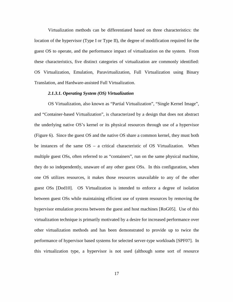
2.1.3.1. Operating System (OS) Virtualization
OS Virtualization, also known as “Partial Virtualization”, “Single Kernel Image”,
and “Container-based Virtualization”, is characterized by a design that does not abstract
the underlying native OS’s kernel or its physical resources through use of a hypervisor
(Figure 6). Since the guest OS and the native OS share a common kernel, they must both
be instances of the same OS – a critical characteristic of OS Virtualization. When
multiple guest OSs, often referred to as “containers”, run on the same physical machine,
they do so independently, unaware of any other guest OSs. In this configuration, when
one OS utilizes resources, it makes those resources unavailable to any of the other
guest OSs [Dod10]. OS Virtualization is intended to enforce a degree of isolation
between guest OSs while maintaining efficient use of system resources by removing the
hypervisor emulation process between the guest and host machines [RoG05]. Use of this
virtualization technique is primarily motivated by a desire for increased performance over
other virtualization methods and has been demonstrated to provide up to twice the
performance of hypervisor based systems for selected server-type workloads [SPF07]. In
this virtualization type, a hypervisor is not used (although some sort of resource
18
arbitration may occur within the kernel), the guest OSs do not require modification, and
the performance impact of virtualization on the system is minimized.
Figure 6. OS Virtualization Adapted from [Dod10]
Examples of OS Virtualization include the Unix chroot operation, Linux-VServer, Open
VZ, and the FreeBSD Jail mechanism (SPF07).
2.1.3.2. Emulation
Emulation, also called CPU simulation, is characterized by a Type II pure
software hypervisor which runs as an application within the host OS and translates
instructions received from the guest OS into instructions compatible with the underlying

19
Figure 7. Emulation Architecture (Figure 7). When a guest OS makes system calls to the virtualized
hardware, the hypervisor translates those calls into instructions which are compatible
with the underlying hardware using a process called dynamic binary translation. These
translated instructions are passed to host OS which relays them to the underlying
architecture. This process completely abstracts the physical layer, making it possible for
the hypervisor to emulate physical features that do not actually exist, to include emulation
of a CPU that does not match the underlying CPU [Fer08]. The chief benefit of
emulation is the flexibility to run guest OSs that require physical hardware which may or
may not physically exist within the system [Gol08]. This flexibility comes at a
significant performance cost due to the overhead caused by the burden of dynamic
translation and the added constraint that the emulator cannot directly access the hardware
[DFL11]. A limited benefit of hardware emulation is its usefulness in providing
backwards compatibility for older, obsolete technologies. This is helpful for retaining
20
access to preserved data on legacy systems [HHK09]. Emulator examples include Bochs,
Hydra, and QEMU [Bel05] [Fer08].
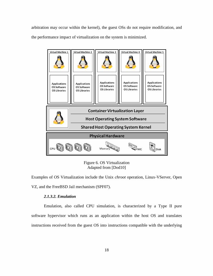
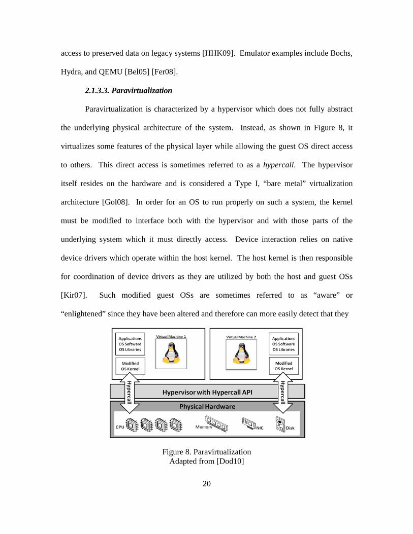
2.1.3.3. Paravirtualization
Paravirtualization is characterized by a hypervisor which does not fully abstract
the underlying physical architecture of the system. Instead, as shown in Figure 8, it
virtualizes some features of the physical layer while allowing the guest OS direct access
to others. This direct access is sometimes referred to as a hypercall. The hypervisor
itself resides on the hardware and is considered a Type I, “bare metal” virtualization
architecture [Gol08]. In order for an OS to run properly on such a system, the kernel
must be modified to interface both with the hypervisor and with those parts of the
underlying system which it must directly access. Device interaction relies on native
device drivers which operate within the host kernel. The host kernel is then responsible
for coordination of device drivers as they are utilized by both the host and guest OSs
[Kir07]. Such modified guest OSs are sometimes referred to as “aware” or
“enlightened” since they have been altered and therefore can more easily detect that they
Figure 8. Paravirtualization Adapted from [Dod10]
21
are running as a VM. Since the guest OS kernel must be modified in order to make direct
calls to the physical hardware, only those OSs which can be modified can be
implemented on a paravirtualized system. Closed source OSs, such as Microsoft
Windows, cannot be paravirtualized since they are proprietary and their kernel cannot be
modified. Hyper-V, a Microsoft-created, hypervisor-based virtualization system, has
features that attempt to implement paravirtualization however, due to the inability to
modify the OS kernel, Microsoft systems still cannot be paravirtualized in the strictest
sense of the term. Open source OSs, such as Linux, often come with paravirtualization
APIs which support paravirtualization. Paravirtualization provides increased system
performance over dynamic binary translation techniques used by emulation and full
virtualization through use of hypercalls. Hypercalls allow direct access to underlying
hardware while avoiding the costs associated with trapping and interpreting every
individual instruction. Additionally, through use of built-in paravirtualization APIs
within the guest OS, such systems are particularly unique in their ability to share data
between guest OSs [Kir07] [Dod10]. Examples of paravirtualization include some
versions of VMware, ESX, and Xen.
2.1.3.4. Full Virtualization
Full virtualization simulates all aspects of a physical computer such that guest
OSs are able to run unmodified directly on the simulated physical architecture of the host
machine (Figure 9) [Dod10]. Full virtualization is similar to emulation in that it uses
binary translation and requires no modifications to the guest OS; however, it is different
in that full virtualization hypervisors are Type I while emulation hypervisors are
22
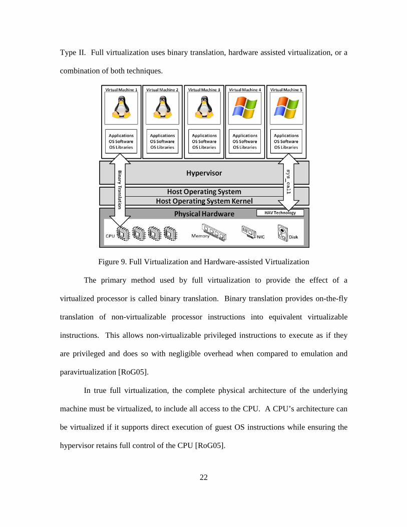
Type II. Full virtualization uses binary translation, hardware assisted virtualization, or a
combination of both techniques.
Figure 9. Full Virtualization and Hardware-assisted Virtualization
The primary method used by full virtualization to provide the effect of a
virtualized processor is called binary translation. Binary translation provides on-the-fly
translation of non-virtualizable processor instructions into equivalent virtualizable
instructions. This allows non-virtualizable privileged instructions to execute as if they
are privileged and does so with negligible overhead when compared to emulation and
paravirtualization [RoG05].
In true full virtualization, the complete physical architecture of the underlying
machine must be virtualized, to include all access to the CPU. A CPU’s architecture can
be virtualized if it supports direct execution of guest OS instructions while ensuring the
hypervisor retains full control of the CPU [RoG05].
23
Up until recently, this practice was impractical for x86 processors since they were
not designed with virtualization functionality built into the processor. Technologies such
as Hardware-assisted Virtualization (HAV) address this constraint by extending the
processor to support virtualization by direct execution.
To enable direct execution, the processor instruction set architecture is extended
to provide extra instructions which directly support virtualization [Kir07] [Fer08]. The
ability to support simultaneous states for both the hypervisor and the guest OS within the
processor is critical to HAV and requires additional processor capabilities. Two
examples of HAV are Intel’s VT-x technology and AMD Virtualization (AMD-V). Both
extend hypervisor operation into the CPU, allowing faster execution of guest OS code
directly on the processor while maintaining the equivalency, efficiency, and control
constraints required for virtualization [HeA11] [PoG74].
AMD-V offers Secure Virtual Machine (SVM) extensions which create and
manage the virtualized and non-virtualized states (contexts) within the processor. Also
included is a Virtual Machine Control Block (VMCB), a memory structure which stores
both native and virtual machine context data. This enables two mutually exclusive modes
of CPU access and execution for the hypervisor and guest OS. See [MyY07] for an
excellent discussion of AMD-V functionality specifically as it relates to HAV-R.
Intel’s VT-x also provides two mutually exclusive modes of CPU access and
execution: VMX root operation (host mode) and VMX non-root operation (guest mode).
An in-memory Virtual Machine Control Structure (VMCS), similar to AMD-V’s VMCB,
controls transitions between the two modes via two instructions: VM-Entry (transition
from VMX root mode to non-root mode) and VM-Exit (transition from VMX non-root
24
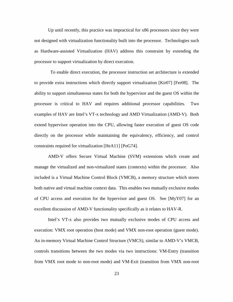
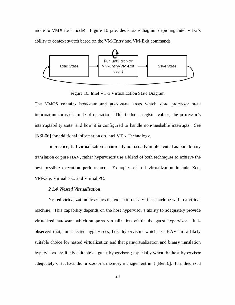
mode to VMX root mode). Figure 10 provides a state diagram depicting Intel VT-x’s
ability to context switch based on the VM-Entry and VM-Exit commands.
Figure 10. Intel VT-x Virtualization State Diagram The VMCS contains host-state and guest-state areas which store processor state
information for each mode of operation. This includes register values, the processor’s
interruptability state, and how it is configured to handle non-maskable interrupts. See
[NSL06] for additional information on Intel VT-x Technology.
In practice, full virtualization is currently not usually implemented as pure binary
translation or pure HAV, rather hypervisors use a blend of both techniques to achieve the
best possible execution performance. Examples of full virtualization include Xen,
VMware, VirtualBox, and Virtual PC.
2.1.4. Nested Virtualization
Nested virtualization describes the execution of a virtual machine within a virtual
machine. This capability depends on the host hypervisor’s ability to adequately provide
virtualized hardware which supports virtualization within the guest hypervisor. It is
observed that, for selected hypervisors, host hypervisors which use HAV are a likely
suitable choice for nested virtualization and that paravirtualization and binary translation
hypervisors are likely suitable as guest hypervisors; especially when the host hypervisor
adequately virtualizes the processor’s memory management unit [Ber10]. It is theorized
25
that once a HAV hypervisor has been activated, no other HAV hypervisor installed later
can gain complete control of the system. The first hypervisor is thought to retain ultimate
control and therefore may have a prophylactic effect against hypervisor subversion
[Fer08]. The extent of this potential prophylactic effect is unknown. Additionally, recent
nested virtualization research concludes that efficient nested virtualization is feasible but
notes that nesting hypervisors may have a multiplicative effect on the execution time of
selected instructions. Most recent nested hypervisor developments have extended nested
virtualization functionality from supporting only 32-bit innermost virtual machines to
successfully nesting 64-bit virtual machines [BDD10].
2.1.5. Virtual Machine Introspection
Virtual Machine Introspection (VMI) is the practice of using the hypervisor to
observe the internal state of a guest OS. This is used to analyze activity within the guest
OS through use of a priori knowledge of the system [GaR03]. The VMI agent may
reside within the hypervisor or outside the hypervisor and within the host OS. When the
VMI agent exists outside the hypervisor, it uses an application programming interface
provided by the hypervisor to gather data about the guest OS. VMI tools are classified as
monitoring or intervening. Monitoring VMI reports on targeted behaviors of the guest
OS while intervening VMI automatically intervenes in response to a targeted behavior.
This distinction between monitoring and intervention parallels and is related to the
security concepts of detection and response. To appropriately intervene, the VMI tool
must have some pre-programmed way to interpret the behavior of the guest OS. This
link, between behavior and meaning, is referred to as semantic awareness [NBH08].
26
2.1.5.1. Semantic Awareness
Semantic awareness is the ability to interpret an event or behavior based on
context and knowledge [NBH08]. As discussed earlier, the computer can be considered a
mathematical model and an abstraction of reality. As such, meaning is imparted solely
by the programmer. From the hypervisor perspective, register values, memory pages,
disk blocks and low-level events occurring within the emulated hardware are observed
but not easily interpreted into particular OS-specific behaviors, much less categorized as
malicious or benign activity. This uncertainty between the raw data which is observed by
the hypervisor and the OS-specific contextual meaning of that data is referred to as the
semantic gap [Dod10]. Techniques for bridging the semantic gap generally rely on
identifying pre-defined, OS-specific data structures and using them as templates to
dynamically interpret the internal state of the guest machine [BJW10]. This ability to
introspect the internal state of the machine provides enhanced situational awareness over
other external-to-the-guest machine monitoring techniques because the guest OS has little
to no control over the ability of the hypervisor to observe the guest OS’s actions. As
such, hypervisors are assumed to provide a trusted platform for VMI and enhanced
situational awareness of the guest OS.
2.1.5.3. Forensics and Malware Analysis
Non-virtualized forensic tools suffer from incomplete and inaccurate information
due to two common scenarios. The first occurs when the target machine is compromised
and taken offline for forensics examination. The act of taking it offline disturbs the
internal state of the machine and obscures evidence of the attack. The second occurs
when forensics tools are applied to a target machine while it is experiencing a malicious
27
attack. In this case, placing forensics tools on the target machine disturbs the state of the
machine, also obscuring evidence of the attack and possibly notifying the attacker or
malicious program that it is being monitored [NHB09].
VMI has particular value in the field of computer forensics where it provides
security researchers with a presumed-to-be isolated laboratory which possesses an
intimate introspective vantage point from which to observe malicious code as it acts on a
target machine. As a forensic tool, VMI offers a unique opportunity to observe the
internal state of the machine, both during and after a malicious event, without disturbing
the malicious program or altering data [NHB09]. In this sense, it can be considered a
covert forensics tool [Nen08]. Virtualization-based forensics provides the added benefit
that once malware has been executed within a virtual machine, it can almost instantly be
reverted back to a pre-infected state without the time-consuming manual reinstallation
which would be required to restore a native OS. This reduces the overall time and cost of
malware analysis and makes VMI an efficient tool for forensic examination [VPM11].
The forensic effectiveness of VM introspection has made VM-based malware analysis
the primary research methodology for detection and infiltration of botnets and other
malicious code [Fer08] [San09] [VuA11] [VPM11].
2.1.6. Benefits of Virtualization
The benefits of virtualization can be categorized in regard to efficiency and cost
effectiveness, flexibility, disaster recovery, and security.
2.1.6.1. Efficiency and Cost Effectiveness
As discussed in Section 2.1, one of the earliest motivations behind the
development of virtualization was a desire to more efficiently utilize computational
28
resources [Cre81]. According to one source, many data centers have servers running at
only 10% to 15% of total processing capacity [Gol08]. The ability of virtualization to
dynamically share system resources among multiple guest OS’s results in greater average
usage of the overall system since idle resources, such as unused CPU cycles, can be used
by whichever guest OS needs them [JML10]. Through virtualization techniques,
hardware utilization rates can be raised as high as 70% to 80% [Gol08]. Virtualization is
also cost efficient due to reduced downtime caused by the ability to migrate live
machines from one physical system to another without interrupting service as well as the
ability to upgrade portions of the physical system without taking the entire system offline
[JML10]. Finally, the need for many small servers can be mitigated by installing virtual
servers on fewer physical systems, resulting in fewer physical machines, lower overall
purchase cost, and reductions in required manpower, floor space, utility costs, and
cooling requirements.
2.1.6.2. Flexibility
The ability of the hypervisor to control the state of the guest OSs makes it
possible to pause, restart, shutdown, and revert VMs to a previous state [JML10].
Additionally, in implementations where the hypervisor translates messages between the
guest OS and underlying physical architecture, the machine itself can be easily replicated
and transferred to any number of differently configured underlying architectures all
without losing the ability to execute the VM [CPW09]. This makes VMs likely to stay
compatible with future architectures as well as able to use older technologies that can be
translated for execution on modern systems [HHK09]. Finally, virtualization enables the
use of a wide variety of operating systems and applications on a single architecture,
29
making it much easier and quicker to implement new OSs and applications when
compared to non-virtualized architectures [Gol08].
2.1.6.3. Disaster Recovery
The ability to restore a virtual machine to a previous state with little to no
availability loss in many ways captures the essence of disaster recovery. Since the
physical architecture is fully abstracted by the hypervisor, a virtual machine can be
dynamically saved and then rapidly restored even if the original physical architecture has
been completely destroyed (this assumes the VM state was copied prior to the disaster).
Virtualization monitoring software can be configured such that, if a virtual system
catastrophically fails, it can be automatically instantiated at another geographic location
with minimal service interruption [Gol08].
2.1.6.4. Security
With full virtualization and emulation, the guest OSs run within their own kernel.
Since they do not directly interact with the host kernel, if a guest OS becomes infected
with malware, it will likely stay contained within that guest OS’s virtual environment
[RoG05]. This is because the abstraction of the underlying physical architecture by the
hypervisor effectively isolates each guest from the host machine and all other guests. To
further leverage this benefit beyond simply protecting a single guest, critical applications
and process are split among guests so that if one is compromised, other systems can
continue to function correctly and provide a needed service [JML10]. The hypervisor
itself provides a unique security capability through its ability to completely mediate
interactions between the host software and the underlying hardware [GaR03].
30
2.2. Hypervisors (Virtual Machine Managers)
The following describes the particular hypervisors used in this thesis. They are
QEMU, VirtualBox, VMware Workstation, and VMware ESXi. BluePill, a true
hypervisor rootkit, is discussed in Section 2.4, Subverting the Host: HAV Rootkits.
2.2.1. QEMU 0.9.0
QEMU 0.9.0, The Quick EMUlator is an open source, software-based processor
emulator which uses a read-decode-execute loop to translate instructions from those
offered by the virtual machine to the guest OS into an instruction set compatible with the
underlying hardware. QEMU does not support communication between the host and
guest machine since it is designed to emulate a stand-alone system [Fer08]. It has two
modes of operation: user-mode and full system emulation. User-mode emulation allows
cross-compiled executables to run while full system emulation mode emulates a full
system to include the corresponding hard disk image and all peripherals. Because it runs
as an application within a host operating system environment, it is considered a Type II
hypervisor. An extension for QEMU called KVM (Kernel-based Virtual Machine) exists
which uses HAV to improve QEMU performance [KVM12]. QEMU detection
techniques are documented in [Fer08].
2.2.2. VirtualBox 4.1.10
Oracle’s VirtualBox was originally designed as a pure-software full virtualization
hypervisor however, as of release 2.0, it also provides hardware-assisted full
virtualization. It supports Windows, Mac OS X, Linux, and Solaris hosts. Because it
uses binary translation, it can run both 32-bit systems on 64-bit machines and 64-bit
systems on 32-bit machines, though at the risk of exceptionally high overhead for 64-bit
31
systems on 32-bit machines. As of the time of this writing, VirtualBox required use of
HAV for execution of 64-bit systems [Ora12].
2.2.3. VMware Workstation 8
VMware Workstation 8 is a hosted, Type II hypervisor which supports
simultaneous execution of multiple virtual machine environments and their
corresponding guest OSs. It is primarily designed to virtualize desktop OSs and is
configurable for both binary translation and HAV full virtualization. Trivial VMware
Workstation detection mechanisms are documented by [Fer08]. VMware Workstation 8
is able to virtualize the functionality of the underlying HAV processor and supports
nested virtualization of 32-bit and 64-bit systems.
2.2.4. VMware ESXi 5.0
Whereas VMware Workstation is intended for desktop virtualization, ESXi 5.0 is
a bare-metal Type I hypervisor intended for server use. In comparison with other
hypervisors, it is relatively thin, with a code-base footprint of less than 150 MB compared
to 1 GB for Citrix Xen Server 5.6, 2 GB for ESX and 3 GB for Microsoft’s Hyper-V
[VMW12]. ESXi achieves its small size by implementing its graphical user interface in a
separate application, the vSphere client, which is used to remotely manage the hypervisor
over a network connection (see Figure 11). It supports virtualization of the underlying
Intel VT-x or AMD-V HAV-enabled processor which allows it to nest HAV VMs. It
provides this functionality for both 32-bit and 64-bit guest OSs. It is observed that, for
purposes of this research, ESXi exhibits characteristics which are desirable in a notional
HAV-R.
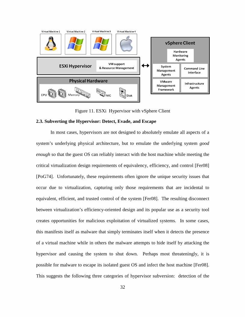
32
Figure 11. ESXi Hypervisor with vSphere Client
2.3. Subverting the Hypervisor: Detect, Evade, and Escape
In most cases, hypervisors are not designed to absolutely emulate all aspects of a
system’s underlying physical architecture, but to emulate the underlying system good
enough so that the guest OS can reliably interact with the host machine while meeting the
critical virtualization design requirements of equivalency, efficiency, and control [Fer08]
[PoG74]. Unfortunately, these requirements often ignore the unique security issues that
occur due to virtualization, capturing only those requirements that are incidental to
equivalent, efficient, and trusted control of the system [Fer08]. The resulting disconnect
between virtualization’s efficiency-oriented design and its popular use as a security tool
creates opportunities for malicious exploitation of virtualized systems. In some cases,
this manifests itself as malware that simply terminates itself when it detects the presence
of a virtual machine while in others the malware attempts to hide itself by attacking the
hypervisor and causing the system to shut down. Perhaps most threateningly, it is
possible for malware to escape its isolated guest OS and infect the host machine [Fer08].
This suggests the following three categories of hypervisor subversion: detection of the
33
virtual environment, evasion of detection and VM introspection, and escape of malicious
code out of the guest machine and into the host.
2.3.1. VM Detection
The smallest failure of a hypervisor to perfectly simulate “native” machinery in
support of a VM creates disparities which suggest a non-native environment. Attackers
that detect such disparities can alter their malware to evade and attack VMI or the VM
environment [ZhC07]. This section addresses detection techniques used by attackers to
detect a virtualized environment prior to compromise of the guest OS. As such, it
focuses on those techniques that can be performed from within Ring 3 of the guest.
Detection techniques used by a possibly compromised host to detect the presence of a
HAV-R are addressed in Section 2.5.
Indicators that suggest a virtual environment are referred to as virtualization
markers. Several are discussed in this section, organized into the following taxonomy
suggested by [CAM08]: Hardware, Execution Environment, Application, and Behavioral
Virtualization Markers.
2.3.1.1. Hardware Virtualization Markers
Hardware virtualization markers are unique device or driver characteristics which
can be used to differentiate virtualized from native hardware. This information is often
non-privileged and is usually trivially detected by gathering information directly from a
particular system’s hardware during a process referred to as hardware fingerprinting.
Hardware fingerprinting uses built-in, user-level components of the standard
operating system to query hardware settings. This data is checked for indications of the
existence of virtualization [LeM08]. Two trivial methods of hardware fingerprinting
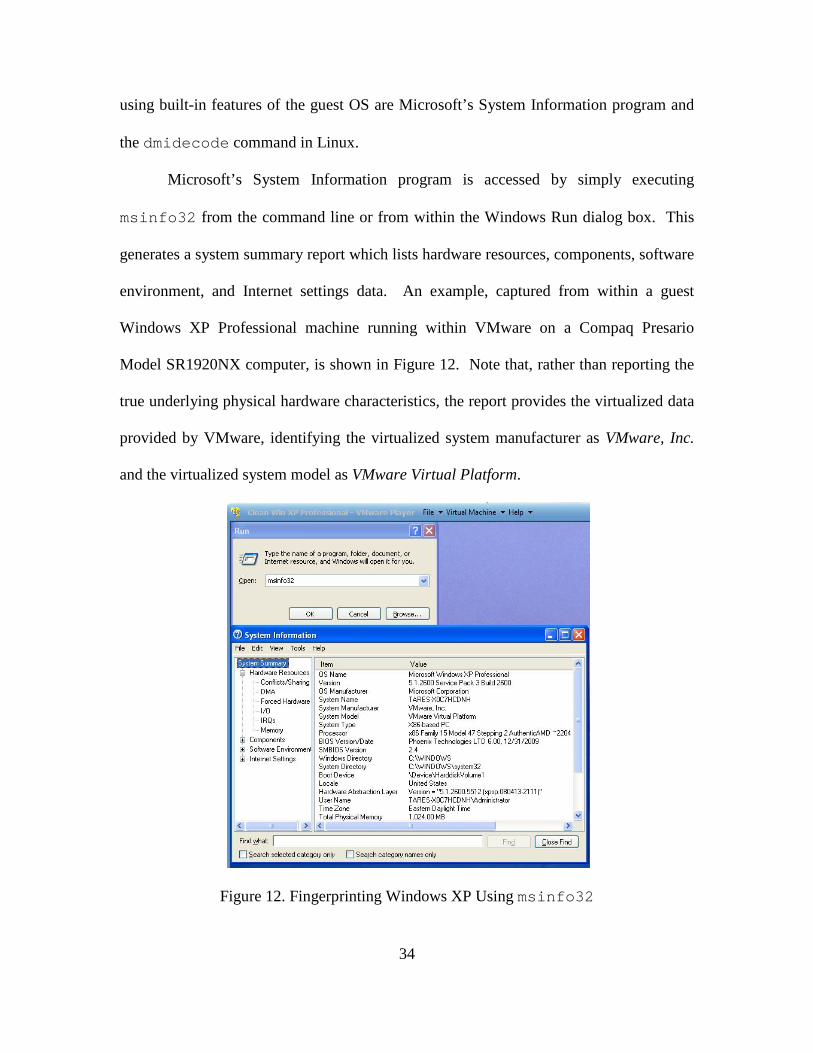
34
using built-in features of the guest OS are Microsoft’s System Information program and
the dmidecode command in Linux.
Microsoft’s System Information program is accessed by simply executing
msinfo32 from the command line or from within the Windows Run dialog box. This
generates a system summary report which lists hardware resources, components, software
environment, and Internet settings data. An example, captured from within a guest
Windows XP Professional machine running within VMware on a Compaq Presario
Model SR1920NX computer, is shown in Figure 12. Note that, rather than reporting the
true underlying physical hardware characteristics, the report provides the virtualized data
provided by VMware, identifying the virtualized system manufacturer as VMware, Inc.
and the virtualized system model as VMware Virtual Platform.
Figure 12. Fingerprinting Windows XP Using msinfo32
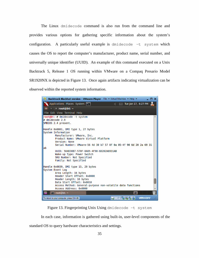
35
The Linux dmidecode command is also run from the command line and
provides various options for gathering specific information about the system’s
configuration. A particularly useful example is dmidecode -t system which
causes the OS to report the computer’s manufacturer, product name, serial number, and
universally unique identifier (UUID). An example of this command executed on a Unix
Backtrack 5, Release 1 OS running within VMware on a Compaq Presario Model
SR1920NX is depicted in Figure 13. Once again artifacts indicating virtualization can be
observed within the reported system information.
Figure 13. Fingerprinting Unix Using dmidecode –t system
In each case, information is gathered using built-in, user-level components of the
standard OS to query hardware characteristics and settings.
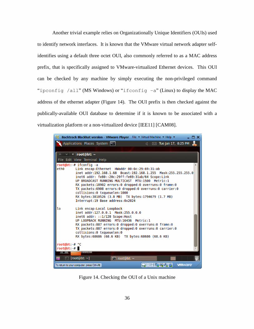
36
Another trivial example relies on Organizationally Unique Identifiers (OUIs) used
to identify network interfaces. It is known that the VMware virtual network adapter self-
identifies using a default three octet OUI, also commonly referred to as a MAC address
prefix, that is specifically assigned to VMware-virtualized Ethernet devices. This OUI
can be checked by any machine by simply executing the non-privileged command
“ipconfig /all” (MS Windows) or “ifconfig –a” (Linux) to display the MAC
address of the ethernet adapter (Figure 14). The OUI prefix is then checked against the
publically-available OUI database to determine if it is known to be associated with a
virtualization platform or a non-virtualized device [IEE11] [CAM08].
Figure 14. Checking the OUI of a Unix machine
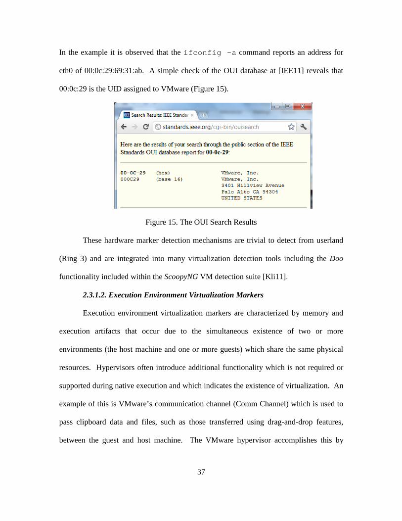
37
In the example it is observed that the ifconfig -a command reports an address for
eth0 of 00:0c:29:69:31:ab. A simple check of the OUI database at [IEE11] reveals that
00:0c:29 is the UID assigned to VMware (Figure 15).
Figure 15. The OUI Search Results
These hardware marker detection mechanisms are trivial to detect from userland
(Ring 3) and are integrated into many virtualization detection tools including the Doo
functionality included within the ScoopyNG VM detection suite [Kli11].
2.3.1.2. Execution Environment Virtualization Markers
Execution environment virtualization markers are characterized by memory and
execution artifacts that occur due to the simultaneous existence of two or more
environments (the host machine and one or more guests) which share the same physical
resources. Hypervisors often introduce additional functionality which is not required or
supported during native execution and which indicates the existence of virtualization. An
example of this is VMware’s communication channel (Comm Channel) which is used to
pass clipboard data and files, such as those transferred using drag-and-drop features,
between the guest and host machine. The VMware hypervisor accomplishes this by
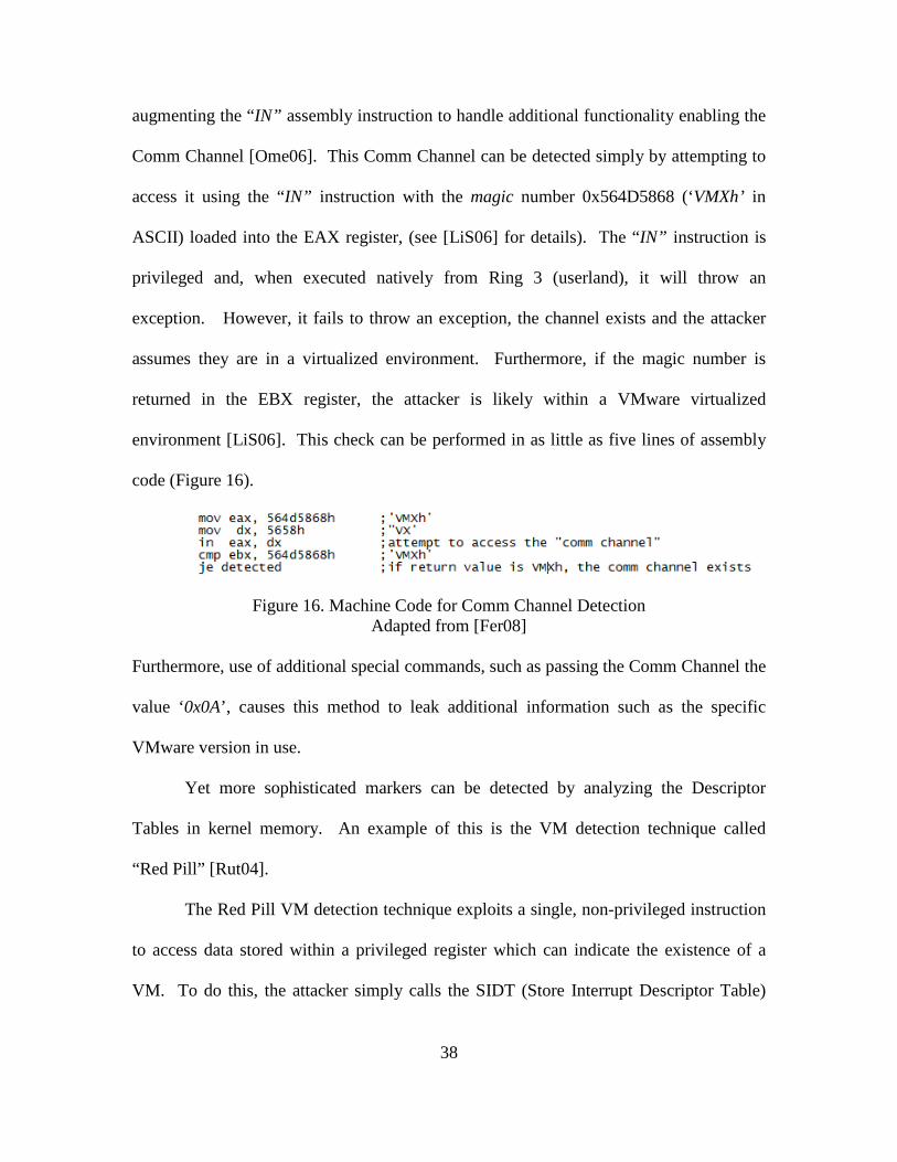
38
augmenting the “IN” assembly instruction to handle additional functionality enabling the
Comm Channel [Ome06]. This Comm Channel can be detected simply by attempting to
access it using the “IN” instruction with the magic number 0x564D5868 (‘VMXh’ in
ASCII) loaded into the EAX register, (see [LiS06] for details). The “IN” instruction is
privileged and, when executed natively from Ring 3 (userland), it will throw an
exception. However, it fails to throw an exception, the channel exists and the attacker
assumes they are in a virtualized environment. Furthermore, if the magic number is
returned in the EBX register, the attacker is likely within a VMware virtualized
environment [LiS06]. This check can be performed in as little as five lines of assembly
code (Figure 16).
Figure 16. Machine Code for Comm Channel Detection Adapted from [Fer08]
Furthermore, use of additional special commands, such as passing the Comm Channel the
value ‘0x0A’, causes this method to leak additional information such as the specific
VMware version in use.
Yet more sophisticated markers can be detected by analyzing the Descriptor
Tables in kernel memory. An example of this is the VM detection technique called
“Red Pill” [Rut04].
The Red Pill VM detection technique exploits a single, non-privileged instruction
to access data stored within a privileged register which can indicate the existence of a
VM. To do this, the attacker simply calls the SIDT (Store Interrupt Descriptor Table)
39
instruction from within the guest OS and examines the return value. The SIDT
instruction is designed to return the stored address of the system’s Interrupt Descriptor
Table (IDT). Since most x86 processors do not support true full virtualization and
therefore do not provide a second IDT register (IDTR) for use by the guest OS, the
hypervisor is forced to virtualize the guest OS’s IDTR somewhere other than the real
IDTR which is reserved for the host OS. If the SIDT instruction is invoked from within a
virtual machine, it will receive the address of its virtualized IDT. When this address
matches commonly used relocation addresses, typically higher in memory than when the
OS is run natively, it is assumed to be operating within a virtualized environment
[Rut04]. It was observed that on VMware VMs, the IDT is typically located at
0xffXXXXXX, and on Virtual PC VMs, it is typically located at 0xe8XXXXXX.
Implementations of the Red Pill technique usually conclude the existence of
virtualization if the IDTR is greater than 0xd0000000 [CLS07]. This test is effective for
both Windows and Linux implementations and is not vendor specific. The technique is
considered reliable for VMs running within a host machine with a single core processor
however, if a multi-core processor or multiple processors are used, it is less conclusive.
This is because within a single processor environment, the IDTR value is constant
whereas with multiple processors (or cores) each will have its own IDT [QuS05]. There
exist other methods, such as NoPill, and ScoopyNG that implement variations of the Red
Pill method to detect virtualization [Ome06] [ZhC07]. Notably, NoPill relies on a similar
algorithm but also examines the Local Descriptor Table (LDT) instead of just the IDT
[QuS05]. ScoopyNG implements both the IDT and LDT check techniques but then goes
40
a step further by checking the memory location of the Global Descriptor Table (GDT)
[LiS06] [ZhC07].
Virtualization markers within the execution environment can also manifest
themselves as disparities between how illegal opcodes are handled within a virtual versus
a native machine. A good example was already discussed using a magic value to detect
VMware’s Comm Channel. Another example of this is the “Illegal Opcode Exception
Trick” which is used to detect the existence of Virtual PC. Rather than using the “IN”
instruction, as VMware does, Virtual PC alters how specific illegal opcodes are handled
and uses them to pass information between the host and guest machine (another
communication channel). When these illegal opcodes are executed natively, they
generate an exception because they are undefined. However, when executed within a
Virtual PC guest, no exception is generated since the hypervisor processes them as
legitimate opcodes. An attacker needs only to execute one of Virtual PC’s special
opcodes and detect whether or not an exception is thrown to determine if the attacker is
within a Virtual PC guest [Fer08].
Disparities between how illegal opcodes are handled by virtual rather than native
machines are not limited to intentional differences such as in the Virtual PC example.
They also manifest as unintentional implementation differences or anomalies. Virtual PC
provides yet another example in that the hypervisor does not seem to limit the length of
instructions that are handed to it. Usually, instructions over 15 bytes generate a general
protection fault when run natively however, Virtual PC accepts such instructions without
generating the fault, indicating that the attacker is not within a native machine [Fer08].
Whether such implementation inconsistencies are accidental or intentional,
41
the altered execution behavior provides sufficient evidence of a non-native execution
environment [CAM08].
Tools used to detect execution environment virtualization markers include
VMDetect, Jerry, and checkVM [BaK10].
2.3.1.3. Application Virtualization Markers
Application virtualization markers include programs or executables that are
installed within the guest OS to facilitate virtualization.
Registry entries and services that reference an underlying hypervisor, such as
references to VMware or VMtools, are examples of application markers that can be used
to detect virtualization [Ome06] [CAM08]. While detection of VM-related registry
entries and services it trivial, it should be noted that it is also relatively simple to rename
processes and registry entries in an attempt to thwart detection [CAM08].
2.3.1.4. Behavioral Virtualization Markers
Behavioral virtualization markers rely on anomalies caused by the hypervisor and
hardware which alter some behavior within the system. Hypervisors, which abstract,
manage, and share the underlying physical architecture, add workload (overhead) to the
system. This overhead is a fundamental property of hypervisors which cannot be avoided
since it is inherent to their function as a management agent within a system.
Simultaneously, the system’s processor(s) have a finite capacity for processing data.
When the overhead caused by the hypervisor is added to the workload already
experienced by the processor, it has the potential of causing a delay, a behavioral
anomaly within the system.
42
Timing-based detection uses this delay to detect virtualization [Fer08]. It does
this by noting the time that it takes to execute a certain set of instructions a specific
number of times on a native machine and then comparing the time it takes to execute the
same instructions on a suspect OS with the same hardware profile. This method relies on
foreknowledge of how long these instructions take to execute on a native machine. The
execution time is then compared to the execution time on a trusted system and, given a
large enough disparity, it can be assumed to be running within a virtualized environment
[Fer08]. The easiest way to do this is through use of a local time source such as the Time
Stamp Counter (TSC) register. Local time sources within the processor present their own
challenges since the hypervisor has complete control over their access and can
intentionally misreport execution times to counter timing-based detection. This and other
behavioral detection techniques are further addressed in Section 2.5, HAV-R Detection.
They are not further addressed in this section as they require privileged access not likely
to be available to a malicious actor in the initial detection stage of hypervisor subversion
and are more likely to be used by the victim to detect HAV-R after subversion.
2.3.1.5. Detection Observations
For the attacker, software is usually more easily changed than hardware, therefore
markers that occur due to a particular hypervisor’s software implementation are generally
more easily eliminated or hidden then those that are a result of a particular hardware
implementation. Additionally, since hypervisor detection can be considered an attack on
a virtualized system, hypervisor designers are likely to make their hypervisor software
increasingly transparent to the guest OS as security risks to hypervisors become more
well known. Those that wish to consistently detect virtualization should focus on
43
detection of those markers which are the most difficult to eliminate from a virtualized
system. Based on the survey of detection techniques discussed in this section, behavioral
virtualization markers that occur due to hardware anomalies are the least susceptible to
change and therefore comprise the most likely successful detection techniques.
2.3.2. Hypervisor Evasion
As discussed earlier, virtualization-based malware analysis has emerged as the
primary research methodology for detection and infiltration of botnets and other
malicious code [San09] [Dod10] [VuA11]. In response, attackers have crafted malware
to behave differently when running within a virtual machine in order to evade detection
and analysis [CAM08]. Malware which behaves differently when executed within a
virtual environment is referred to as “analysis aware malware”, or “split personality
malware” [VPM11]. In a 2008 study, more than forty percent of 6,900 malware samples
examined altered or reduced their malicious behavior when executed within a virtual
machine versus native execution [CAM08].
If an attacker detects the presence of a VM and reduces the malware’s malicious
behavior, the attacker may also attempt to subvert any possible VMI. Such techniques
have already been identified to hide from VMI; one example is Direct Kernel Structure
Manipulation.
2.3.2.1. Direct Kernel Structure Manipulation
Subversion of VMI can be accomplished through compromising the kernel of the
guest OS and manipulating the kernel’s internal data structures through a technique called
Direct Kernel Structure Manipulation (DKSM). This attack was successfully
demonstrated against an Ubuntu guest machine that was introspected by the XenAccess
44
hypervisor. Most VMI tools assume that the guest OS will use its internal kernel data
structures in well-defined, OS-specific and predictable ways. As discussed previously,
these OS-specific definitions are relied upon to provide contextual meaning in order to
bridge the semantic gap. By attacking the assumption that the guest OS adheres to these
definitions, an attacker can successfully obscure the true state of the machine to include
running processes, loaded modules, and active network connections [BJW10].
This attack is divided into three approaches: syntax-based manipulation,
semantics-based manipulation, and a hybrid of both approaches termed “multifaceted
combo manipulation.” Syntax based manipulation involves adding or removing fields
within the internal data structures to cause them to be misidentified by the VMI tool.
This causes the VMI tool to use the wrong template when evaluating the data structure
producing inadvertently garbled data. Semantics based manipulation involves
modification of the underlying semantics of the kernel data structures so that, while the
VMI tool identifies a given data structure, in reality, the data within that structure is being
used differently than how it was defined and therefore will not be detected as suspicious
by the VMI tool. Multifaceted combo manipulation mixes the two techniques to utilize
the best approach to a given situation [BJW10].
2.3.2.2. Detecting VM Evasion
Evasion by malware within the guest machine is detected through use of two
primary strategies.
The first strategy relies on what is already known about evasive and subversive
malware to build a list of behaviors and binary signatures which are indicative of
avoidance behavior. The detection mechanism then logs all sensitive instructions found
45
within or generated by the suspicious binary and reports when they match the behavior
signatures previously identified. This is performed statically or dynamically and is
similar to commonly used signature-based malware detection methods. Unfortunately, its
effectiveness is limited by what is known a priori about avoidance behavior rendering
this method ineffective at detecting unknown virtualization and VMI evasion techniques.
The second strategy relies on the assumption that in order to change behavior
based on detected VMI, the malware must, at some point, make a conditional jump. To
exploit this, the second strategy logs all return values encountered by the potential
malware and then reports if they affect a conditional jump later in the execution. While
this method suffers from a higher rate of false positives, it may reveal novel VM
detection methods [ZhC07].
Both strategies are implemented in Malaware, an academic proof-of-concept
application has been shown to be effective in detection of real-world, VM-evasive
malware [ZhC07].
Once evasive malware is detected, it can be analyzed on a native machine or
analyzed through use of techniques which attempt to trick the malware into concluding
that it is running natively when it is, in fact, running within a VM. The tool
VMDetectGuard uses this technique to detect evasive malware [VPM11].
2.3.2.3. Virtualization as a Deterrent
It is suggested that the propensity of malware to evade virtual environments could
be used as a malware deterrent by signaling that a native environment is virtualized even
when it is not [CAM08]. Such signals are trivial to implement and are as simple as
adding one or more of the detection markers discussed in Section 2.3.1 to a system. Such
46
deception is intended to repel malware attacks and could also be used to funnel attacks
towards intentionally vulnerable systems (honeypots) that are used for malware detection
and research. It is also observed [CAM08] that as potential targets increasingly use
virtualization, the motivation to create malware that can subvert virtualization also
increases thus, as virtualization-oriented malware increases, the benefits of such a
defensive strategy are reduced.
2.3.3. Escaping a VM
One of the unique characteristics of VMs is their ability to isolate the guest OS
from the host and other guests. If that isolation is compromised, it destroys the
assumption that many users have about the security of their virtualized environments.
Because the physical resources of the underlying hardware are shared between the host
and one or more guest OSs, covert channels are possible [Bis02]. The following are two
examples.
In December 2005, it was discovered that VMware contained a vulnerability
within vmnat.exe whereby the hypervisor fails to handle specially crafted “EPRT” and
“PORT” FTP requests, enabling an attacker to overwrite the heap to create a buffer
overflow within the host environment which could allow execution of arbitrary code
[She05]. Additionally, in 2009 it was discovered that there were implementation bugs in
certain SVGA 3D GPU device emulation applications which allowed memory to leak
from the host machine to the guest via a shared buffer. Since the guest OS can also write
to this buffer, it was demonstrated that data written to the frame buffer could be captured
and executed within the host machine [Kor09].
47
There is also a possibility that virtual machines which are allowed to interact
directly with third party devices, such as network and graphics cards, could escape their
host environment by compromising those devices and using them to monitor the system
[Fer08]. A notional example of this would be compromise of a system’s off-board GPU
and then using it to execute malicious code.
In conclusion, it is critically important to note that virtualization is a product of
human programming and is therefore subject to imperfections which can enable
unexpected execution and compromise by a malicious actor. From an attacker’s
perspective, bugs are backdoors.
2.4. Subverting the Host: Hardware-assisted Virtualization Rootkits
Rootkits, in their purest form, are concerned with stealth, avoiding detection by
the target system. They generally achieve their stealth objective by existing at the highest
level of privilege possible or by loading their code and hiding themselves before the
system can detect them [Blu09]. HAV-Rs take the first approach, existing at the highest
level of privilege possible, and use their fully trusted status to hide themselves from
detection by the virtualized system. Such a rootkit is difficult if not impossible to find
using traditional malware approaches since it does not exist within the user space or the
kernel space; rather it exists beneath them, as a bare-metal hypervisor. As a result,
rootkit techniques which look for kernel and user rootkit artifacts (hooking the Interrupt
Descriptor Table or System Service Dispatch Table, patching the master boot record,
Direct Kernel Object Manipulation, among others) are ineffective against HAV-R
detection.
48
HAV-Rs are constrained to HAV-enabled processors such as those which provide
AMD-V and Intel’s VT-x virtualization technologies. This means that each HAV-R must
be tailored to a specific HAV implementation within particular processor class.
Additionally, HAV-Rs effectively invert the forensics, cyber situational
awareness, and VMI paradigm, giving the attacker the ability to introspect and modify
execution within the target machine and making the host OS the introspected target.
Few HAV-Rs are publically known to exist today, two of which are the academic
HAV-Rs BluePill and SubVirt.
2.4.1. BluePill
BluePill implements a novel approach to on-the-fly virtualization where the native
machine is transitioned to a virtual machine through installation of a HAV hypervisor
without rebooting or otherwise altering the formerly native OS. Installation is performed
by loading BluePill using a kernel-mode driver. This can be problematic since current
OSs use driver signing to avoid execution of malicious kernel drivers and bypassing these
constraints is left to the attacker. In practice, bypassing driver signing is possible using
techniques which include memory injection and exploitation of a kernel security flaws,
among others [DFL11]. The kernel driver serves only to load BluePill, not as a container
for BluePill [MyY07]. As such, it needs only exist within the native OS long enough for
the BluePill installation to occur. BluePill’s significance is that it demonstrates the
potential for a malicious hypervisor to transition the native OS into a virtualized state and
to monitor the target OS. Figure 17 graphically represents the following steps which are
used to install the BluePill hypervisor [Fri08] [DFL11].
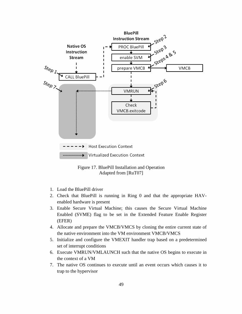
49
Figure 17. BluePill Installation and Operation Adapted from [RuT07]
1. Load the BluePill driver 2. Check that BluePill is running in Ring 0 and that the appropriate HAV-
enabled hardware is present 3. Enable Secure Virtual Machine; this causes the Secure Virtual Machine
Enabled (SVME) flag to be set in the Extended Feature Enable Register (EFER)
4. Allocate and prepare the VMCB/VMCS by cloning the entire current state of the native environment into the VM environment VMCB/VMCS
5. Initialize and configure the VMEXIT handler trap based on a predetermined set of interrupt conditions
6. Execute VMRUN/VMLAUNCH such that the native OS begins to execute in the context of a VM
7. The native OS continues to execute until an event occurs which causes it to trap to the hypervisor
50
When a trap occurs, information about the event that caused the trap is placed into the
VCMB/VMCS so that the hypervisor has access to it. Traps are caused by exceptions,
interrupts, or instruction intercepts. When the hypervisor is ready, it returns execution to
the formerly-native OS using the VMENTRY instruction. The formerly-native OS
proceeds with the next instruction in its instruction stream, oblivious that its context has
changed [MyY07] [RuT07] [DFL11].
Because BluePill exists only within memory on the processor, it cannot survive a
system reboot without being reinstalled from the kernel. As an academic rootkit, it
performs very few secondary functions, the most significant of which is trapping calls the
EFER and flipping the SVME flag to indicate that a hypervisor is not present. BluePill
functionality is currently limited to 64-bit Windows Vista.
2.4.2. SubVirt
Whereas BluePill virtualizes the host machine on the fly, the academic HAV-R
SubVirt installs itself by manipulating the boot sequence such that it loads itself prior to
loading the target OS. To do this, it must be installed within persistent storage on the
target machine prior to a reboot of the system. This is implemented by storing the
SubVirt code in the beginning of the first active partition. The master boot record is then
edited to initiate SubVirt before the target OS. On boot, SubVirt is initiated prior to the
target OS which enables it to create the VM structures necessary to place the target OS
within a virtualized environment. It does this in a similar manner to BluePill in that the
result is that the target OS executes in a virtualized context on the processor. SubVirt
functionality is limited to Windows XP and Linux [KCW06] [Fer08].
51
2.4.3. Characteristics of HAV-R
The HAV-R must be stealthy and therefore must not only flawlessly virtualize the
underlying hardware, it must also avoid any number of potential detection mechanisms.
At a minimum, the following functionality should be implemented to provide a minimum
of detection avoidance:
• Emulation of all processor feature extensions
• Interception of access to off-CPU local timers such as timers contained in
the GPU
• Time Stamp Counter (TSC) manipulation
• Shadow paging implementation to avoid Translation Lookaside Buffer
(TLB) profiling
Additionally, the HAV-R should survive reboot, include covert communication
functionality, and use minimal system resources [MyY07].
2.5. HAV-R Detection
Since HAV relies on specific, iteratively-evolving, and well-defined virtualization
technologies embedded within processor hardware (such as AMD-V and Intel VT-x),
detection techniques which exploit processor behavior are among the most promising
methods for consistent HAV-R detection. By definition, HAV-Rs intercept and arbitrate
communication with underlying processors and memory. Detection techniques that rely
on direct processor and memory access must account for ways that the HAV-R might
misreport the state of the machine. This makes side-channel techniques, which exploit
52
physical and logical constraints of the system and are difficult to subvert, the most
promising method for consistent HAV-R detection.
2.5.1. Execution Profiling
Execution profiling relies on detecting additional processor execution (overhead)
caused by a hypervisor’s trapping of privileged instructions. This is measured
temporally, usually in milliseconds or clock cycles.
While it is possible that software exists that virtualizes the host OS but never traps
on any instruction, such software fails to meet the basic hypervisor requirement of
resource control and arbitration as identified by [PoG74] and cannot be considered a true
hypervisor. Furthermore, such software is likely useless since it would simply permit
uninterrupted data flow between the guest machine and hardware. Hypervisors, by
definition and practical application, must trap some instructions and thereby add
execution overhead to the system.
Timing-based execution profiling using direct access to internal processor
features such as the time stamp counter (TSC) is mentioned in Section 2.3.1. Other
internal processor time sources include the high precision event timer, programmable
interrupt timer, and advanced programmable interrupt timer. While detection using such
timers is possible, it is also possible for the hypervisor to alter the data reported when
attempting to read such counters. Both AMD-V and Intel’s VT-x offer a TSC Offset
feature designed to obscure the impact of virtualization on the TSC by subtracting an
offset from the TSC value before reporting it to the guest OS [MyY07]. This underscores
the importance of using side-channel detection techniques rather than direct techniques
that rely on information that can be arbitrated by the HAV-R. Since the HAV-R is
53
designed specifically for arbitration, identification of side-channel detection techniques
that are unlikely to be compromised is a particularly challenging and important problem.
2.5.1.1. Timing Secure Virtual Machine Enabled Flag Checks
The Secure Virtual Machine Enabled (SVME) flag is a parameter within the
Extended Feature Enable Register (EFER) that is set when a HAV hypervisor is installed
on a machine. A quick way to check if a HAV hypervisor is installed on a system is to
read the EFER to check if the SVME flag is set or clear. If this flag is set and the user is
not explicitly using HAV, a HAV-R is likely present. Unfortunately, calls to the EFER
are privileged and are trivially intercepted and falsified by a HAV-R. While directly
reading the SVME value from the EFER is not a reliable way to detect HAV-R, an
alternative technique is to detect the delay caused by a hypervisor trapping the read EFER
instruction. [Rut07b] and [Fri08] demonstrate that execution of the Read from Model
Specific Register (RDMSR) EFER instruction takes approximately 10 clock cycles on a
particular non-virtualized system, but takes approximately 2,000 to 10,000 clock cycles
respectively after installation of a HAV-R - a significant discrepancy which makes side-
channel detection of EFER trapping a promising detection strategy. Of course, if the
timer used exists within the processor, it is possible for the hypervisor to misrepresent the
returned value. For example, if the TSC is used the HAV-R could simply trap all calls to
the TSC and return a fake value, likely through use of the TSC Offset feature which
subtracts a static value from the TSC. This is unlikely to provide consistently successful
results since the HAV-R would need to generate an offset that, when subtracted from the
value returned by the TSC (which could be in the range of 2,000 to 10,000 clock cycles)
would be non-negative and relatively close to 10. Furthermore, it would need to do so
54
without inducing additional delay to the system which would provide additional evidence
of the HAV-R. This is unlikely and makes checking the Secure Virtual Machine Enabled
Flag a promising detection technique [Fri08].
2.5.1.2. SMP Counting
Since it is possible to successfully cheat internal clocks, external timers and side-
channel timing mechanisms are also used for detection. SMP Counting measures relative
time through use of dual simultaneous processes. In this technique, proposed by [Bar07],
two processes are created within a symmetric multiprocessing (SMP) environment as
close to simultaneously as possible and such that each process executes on its own
dedicated CPU or core. The first process serves as a counter and simply increments a
counter until the second process completes. The second process simultaneously executes
one or more privileged instructions in order to force any existing hypervisor to trap.
Once the second process completes, it notifies the first process which returns the count
value. If the count value is above a certain threshold, it is assumed that the process
experienced one or more traps to a hypervisor. This technique requires previous
measurements of a known non-virtualized system to establish the threshold and is shown
to be effective at detection of non-nested hypervisors [Fri08].
2.5.1.3. Other Execution Profiling Methods
External timing-based detection uses timing sources which are not arbitrated by
the HAV-R to detect processing delays. A potential source for this is the GPU of a
graphics card which could be used to indirectly time execution of privileged instructions
within the CPU. One way to implement such a scheme would be to take several
benchmark readings immediately after the initial setup of the system, when it is assumed
55
to be non-subverted. Further readings would be taken periodically and continually
afterward to assess if the execution time has increased beyond a statistically significant
range. If at any time this range is exceeded, the detection mechanism would report the
possibility of overhead caused by a HAV-R. It is still possible that instructions to the
GPU could be intercepted by the HAV-R however, it is also likely that, in an effort to
make the HAV-R as small as possible, arbitration of extraneous devices such as the
graphics card, might be avoided [MyY07]. Another example of external timing entails
accessing a PCI device register which, on physical hardware, might normally take
hundreds of cycles to read but, when virtualized and maintained within a processor cache,
returns a value in a fraction of the time. Such an anomaly in performance speed, in this
case faster than normal, can also be used for detection [GAW07].
An additional concern is the fidelity of measurements taken outside the processor,
such as measurements in units of whole seconds, which require significantly more
execution of privileged instructions within the suspect processor in order for a
statistically significant reading to be obtained. The uncharacteristic repetition of specific
instructions could make such detection techniques detectable by the HAV-R which could
counter this method by temporarily suspending its trapping operations. This strategy, of
uninstalling or suspending hypervisor trapping when a sustained series of privileged
instructions are executed, is suggested by [Rut07] and is referred to as “BlueChicken”.
The BlueChicken strategy is not without its vulnerabilities since, in order to uninstall and
then reinstall BluePill, it must move itself from Ring -1 to at least the kernel (Ring 0)
where it would behave as a typical rootkit and could be detected using common kernel-
level rootkit detection mechanisms. For the detector, it is less significant whether a
56
HAV-R is detected within the kernel or below the kernel, detection itself is what is most
important therefore, timing-based detection remains a viable detection technique.
2.5.2. Translation Lookaside Buffer Profiling
Another detection mechanism relies on the behavior of hypervisor relative to the
Translation Lookaside Buffer (TLB). The TLB is a fixed-size cache within the CPU that
quickly maps (translates) virtual addresses to physical addresses. When a CPU attempts
to access virtual memory for the first time, it will check its TLB to see if the memory
location is already cached. If it is not, a situation referred to as a TLB miss, it performs
extra work to translate the virtual address to its physical address and stores a copy of the
pairing in the TLB. This process of translating the virtual address to a physical address
requires a page-table walk, which costs three physical memory accesses, the memory is
then accessed, incurring a fourth physical memory access. In contrast, if the memory was
previously accessed and a TLB entry for it exists, the CPU can look up the physical
address within the processor by referencing the TLB and access the location in just a
single physical memory access, incurring only the cost of the TLB check and a single
physical memory access. This is referred to as a TLB hit and makes accessing virtual
locations stored in the TLB roughly four times faster than accessing the same memory
without a pre-existing TLB entry. However, the TLB size is limited and as new locations
are accessed, older pairings are copied over with the latest access pairings according to a
TLB replacement policy [MoE02]. Virtualization adds complexity to the process because
the hypervisor must provide a TLB for both the host and guest OS. Since usually only
one TLB cache is available on the processor, the TLB is usually flushed during context
switches between the guest and host mode. Even if it not flushed, it is likely that one or
57
more TLB entries will be overwritten while the machine is operating in the alternate
context.
To use the TLB to detect virtualization, the detection mechanism uses the TSC to
calculate the time it takes to fill the TLB with new entries. Once the TLB is full, the
detection mechanism executes a privileged instruction that is likely to be trapped but that
minimally alters the TLB, such as the CPUID instruction. Upon interception by a
hypervisor using Intel VT-x HAV, the TLB is completely flushed prior to returning the
context back to the guest OS. The detection mechanism simply checks for this by
accessing the same memory as it did before. If the time it takes to re-access the same
memory locations is significantly less than the time it took to initially populate the TLB,
it is likely that the TLB was not flushed when the CPUID instruction was executed and
therefore the user is within a native OS. However, if the time is similar to the time it
initially took to fill the TLB, the TLB was likely flushed and there is evidence of
virtualization [Fer08].
Not all hypervisors flush the TLB during a context switch. AMD-V in particular
uses an application specific identifier (ASID) to tag TLB entries and preserve them
during a context switch. This leads to an alternate from of TLB detection, TLB Hit
Counting, which also happens to be effective for Intel VT-x systems.
To perform TLB Hit Counting, the TLB is filled by deliberately accessing
specific areas of memory. Once the TLB is full, the page table entries (PTEs) for each
location likely to be cached by the TLB are redirected without altering the TLB to point
to a page with known “magic” values. Next, an instruction that is likely to be trapped by
the hypervisor is executed. In the case of Intel VT-x, the entire TLB is flushed. In other
58
cases, such a with AMD-V systems, at least one entry is likely to change since any
existing hypervisor must read the VMCB’s exit code during the context switch which
will alter at least one TLB entry. Next, the same memory locations that were accessed
during the initial filling of the TLB are accessed a second time. Since the PTEs were
modified to point to a “magic” value, if the TLB experiences a miss, the modified PTEs
are accessed and return a “Hit” on the “magic” values, indicating that a TLB miss has
occurred. The relative change in TLB hits or misses indicate the existence of a
hypervisor [Ada07].
These TLB detection techniques are reliable for hypervisors that flush or
otherwise alter the TLB during context switches. Improvements in how HAV handles the
TLB (such as including a second TLB for virtualization within the processor, supporting
tagged TLBs, or altering how the VMCB is accessed) could make the TLB persistent and
would invalidate these methods [Ber10].
2.6. Conclusion
While not a new concept, the resurgence of virtual machines over the last decade
has altered how we use computers in ways that must be carefully considered. The
efficiency, cost effectiveness, flexibility, disaster recovery, and security benefits provided
by virtualization will likely continue to propel virtualization techniques into mainstream
computing. While these benefits are certainly worth exploiting, it is important to
consider the potential unintended consequences that arise due to their widespread use.
Assumptions, particularly with regard to security, have already proved to be less than
59
completely valid. It is therefore imperative that virtualization and virtual machine
introspection are thoroughly analyzed in order to harden virtualization’s defensive
posture before it is exploited to the detriment of the user.
60
III. Methodology
This chapter discusses the methodology used for this research effort. Section 3.1
describes the problem, goals, and hypothesis of this thesis. Sections 3.2 and 3.3 discuss
the development of the HAV-R detection tool and obfuscation agent which are created to
assist with the experimentation. Sections 3.4 through 3.11 explain the system boundaries,
system services, workload, performance metrics, system parameters, factors, evaluation
technique, and experimental design. Finally, Section 3.12 provides a summary of the
methodology.
3.1. Problem Definition
Virtual machine introspection (VMI) is assumed to provide a trusted platform for
forensic inspection and behavior analysis of malware within a guest OS. However,
previous research demonstrates that it is possible for malware to escape from the guest
into the host and for hardware-assisted hypervisor rootkits (HAV-R) to stealthily
transition the native OS into a virtualized environment [Kor09] [RuT07a]. This suggests
that hypervisor-based VMI scenarios provide an environment where it is possible for
malware to escape the guest into the host, obtain privileged access to the processor, insert
a thin hypervisor rootkit beneath the host, and achieve near-perfect visibility into host and
guest. Within such a scenario, it is not sufficient for a potential victim to simply detect
the presence of a hypervisor, since a trusted hypervisor already exists within the system.
Rather, the potential victim must detect the presence of a second hypervisor, in addition
to the trusted one used for VMI. It is therefore imperative to determine if HAV-R can be
61
detected within a nested virtualized environment, such as that potentially encountered by
a VMI system subverted by a HAV-R.
3.1.1. Goals and Hypothesis
This research effort presents the implementation, analysis, and evaluation of a
rootkit hypervisor detection system which exploits processor and translation lookaside
buffer-based mechanisms to detect HAV-R within nested virtualized systems. It answers
the questions (1) is it possible to detect HAV-R within a nested virtualized environment
using selected detection techniques and (2) how do different virtualization types affect
HAV-R detection using selected techniques? Finally, based on the selected detection
mechanisms, likely countermeasures are implemented and evaluated for effectiveness at
obfuscating the existence of a HAV-R.
The detection techniques used in this research rely on detecting the overhead
(additional workload) encountered by a system as a result of virtualization. It is
hypothesized that the overhead caused by a pre-existing, trusted hypervisor is sufficient
to obfuscate the existence of a HAV-R and that, in cases where the HAV-R is detectable,
deliberate execution of privileged instructions within the guest OS is sufficient to obscure
the HAV-R.
3.1.2. Approach
The experimental approach models a VMI scenario where a user within the native
OS uses a trusted hypervisor to introspect a guest OS containing potential malware. This
is a common, real-world forensics scenario where malware is likely to exist within a
virtualized environment (Section 2.1.5.3). It is assumed that malware within the guest
OS has the ability to install a HAV- R beneath the native OS, causing the native OS to
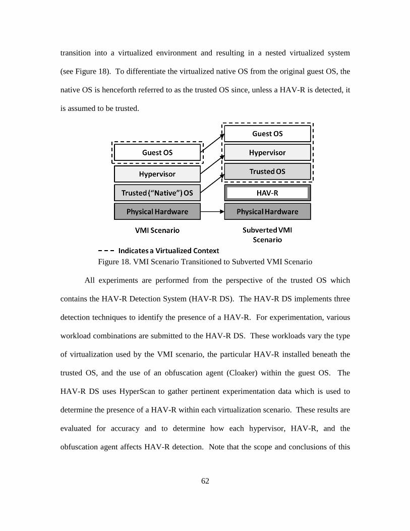
62
transition into a virtualized environment and resulting in a nested virtualized system
(see Figure 18). To differentiate the virtualized native OS from the original guest OS, the
native OS is henceforth referred to as the trusted OS since, unless a HAV-R is detected, it
is assumed to be trusted.
Figure 18. VMI Scenario Transitioned to Subverted VMI Scenario
All experiments are performed from the perspective of the trusted OS which
contains the HAV-R Detection System (HAV-R DS). The HAV-R DS implements three
detection techniques to identify the presence of a HAV-R. For experimentation, various
workload combinations are submitted to the HAV-R DS. These workloads vary the type
of virtualization used by the VMI scenario, the particular HAV-R installed beneath the
trusted OS, and the use of an obfuscation agent (Cloaker) within the guest OS. The
HAV-R DS uses HyperScan to gather pertinent experimentation data which is used to
determine the presence of a HAV-R within each virtualization scenario. These results are
evaluated for accuracy and to determine how each hypervisor, HAV-R, and the
obfuscation agent affects HAV-R detection. Note that the scope and conclusions of this
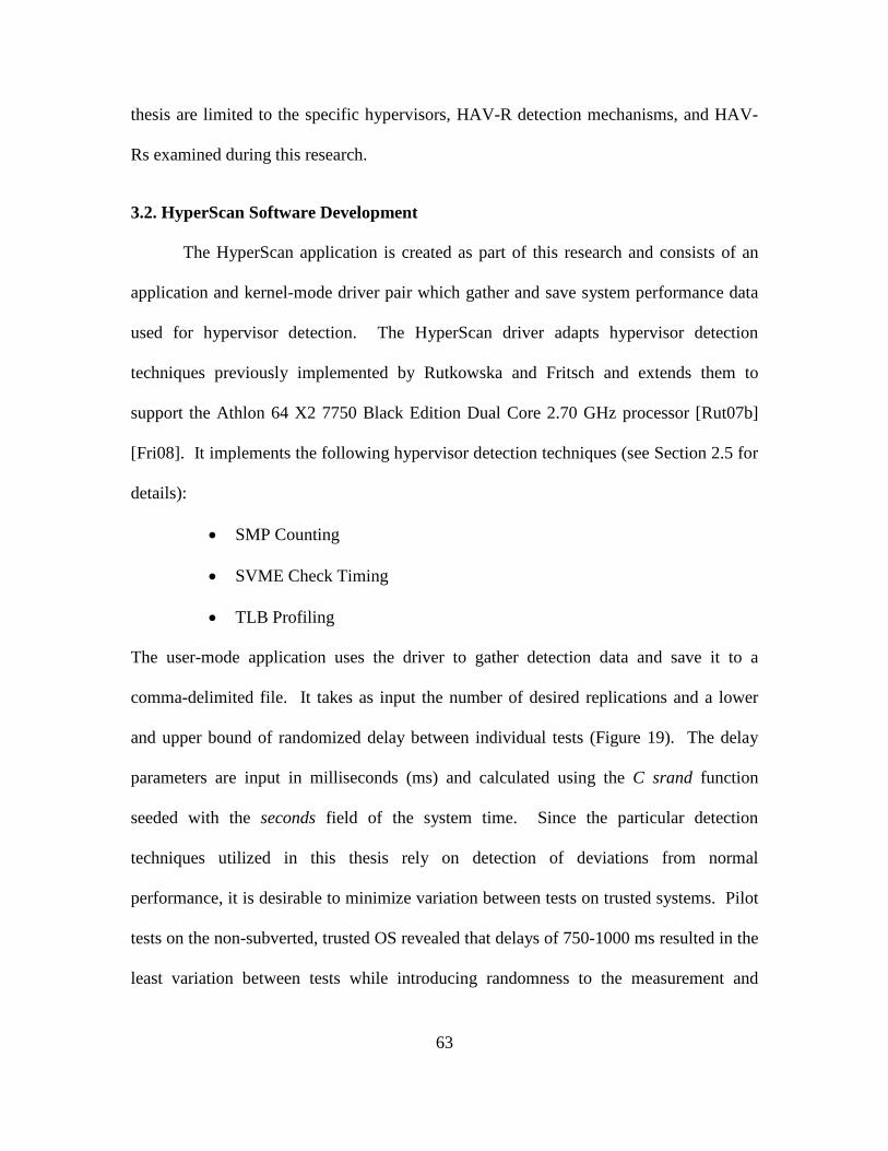
63
thesis are limited to the specific hypervisors, HAV-R detection mechanisms, and HAV-
Rs examined during this research.
3.2. HyperScan Software Development
The HyperScan application is created as part of this research and consists of an
application and kernel-mode driver pair which gather and save system performance data
used for hypervisor detection. The HyperScan driver adapts hypervisor detection
techniques previously implemented by Rutkowska and Fritsch and extends them to
support the Athlon 64 X2 7750 Black Edition Dual Core 2.70 GHz processor [Rut07b]
[Fri08]. It implements the following hypervisor detection techniques (see Section 2.5 for
details):
• SMP Counting
• SVME Check Timing
• TLB Profiling
The user-mode application uses the driver to gather detection data and save it to a
comma-delimited file. It takes as input the number of desired replications and a lower
and upper bound of randomized delay between individual tests (Figure 19). The delay
parameters are input in milliseconds (ms) and calculated using the C srand function
seeded with the seconds field of the system time. Since the particular detection
techniques utilized in this thesis rely on detection of deviations from normal
performance, it is desirable to minimize variation between tests on trusted systems. Pilot
tests on the non-subverted, trusted OS revealed that delays of 750-1000 ms resulted in the
least variation between tests while introducing randomness to the measurement and
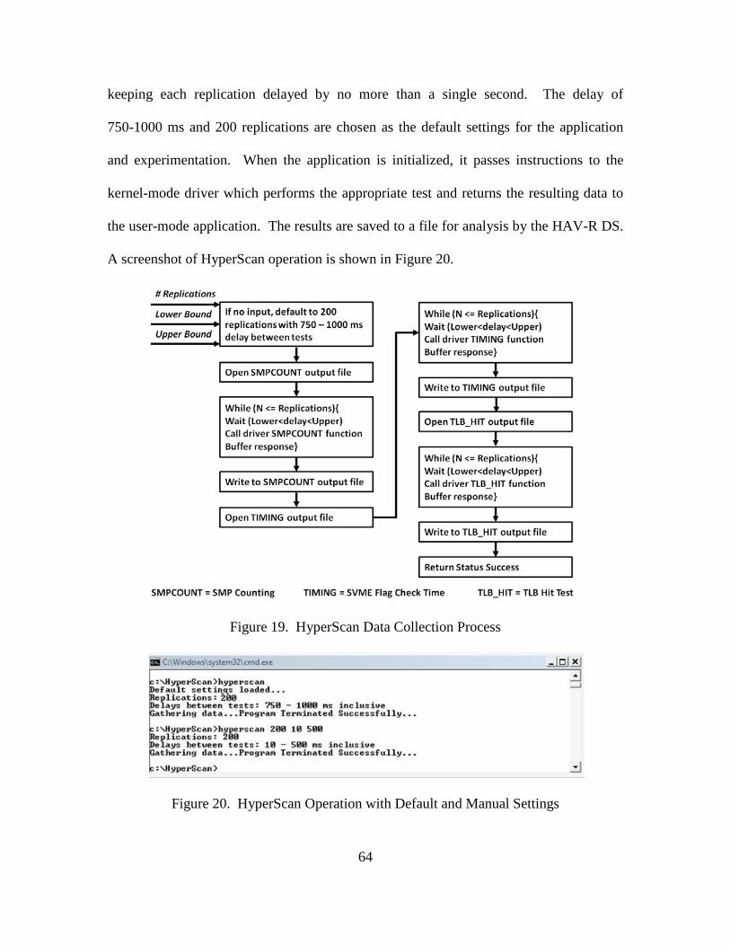
64
keeping each replication delayed by no more than a single second. The delay of
750-1000 ms and 200 replications are chosen as the default settings for the application
and experimentation. When the application is initialized, it passes instructions to the
kernel-mode driver which performs the appropriate test and returns the resulting data to
the user-mode application. The results are saved to a file for analysis by the HAV-R DS.
A screenshot of HyperScan operation is shown in Figure 20.
Figure 19. HyperScan Data Collection Process
Figure 20. HyperScan Operation with Default and Manual Settings
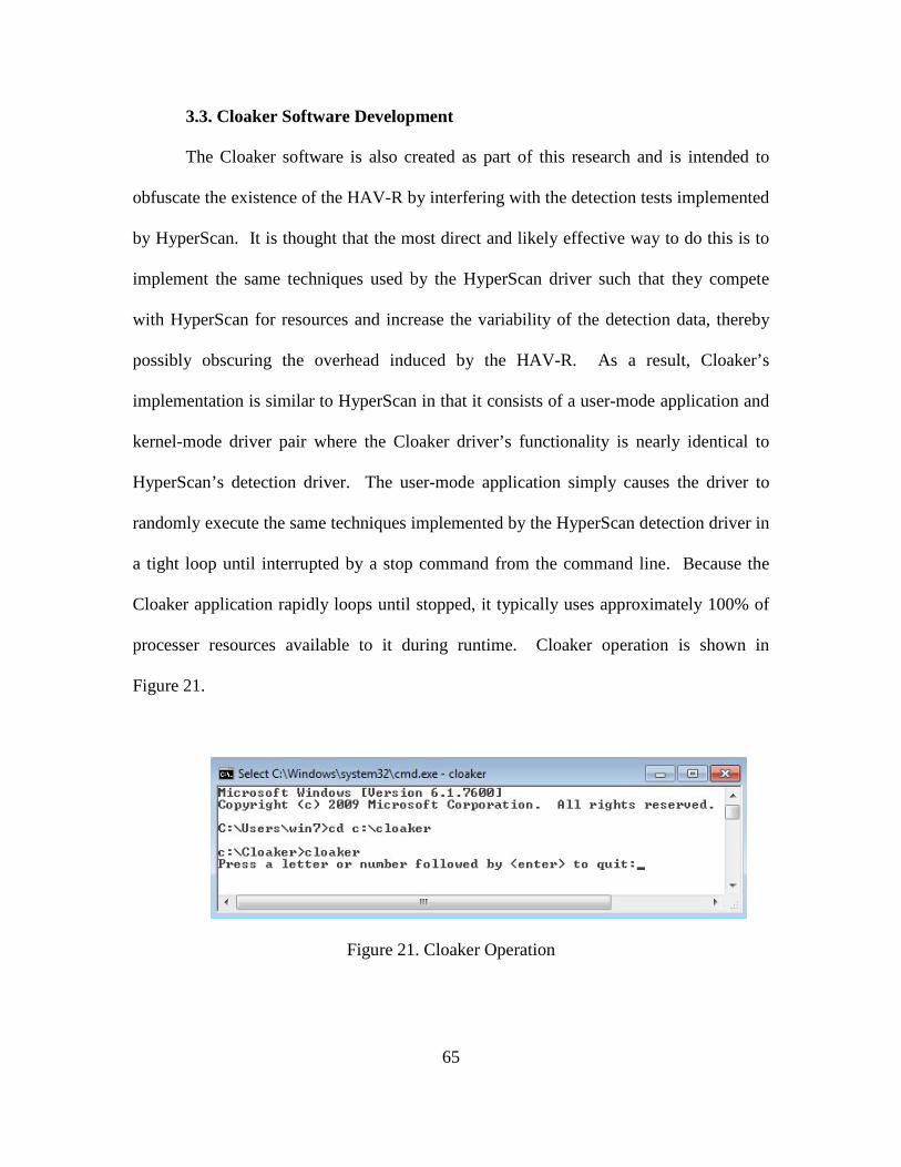
65
3.3. Cloaker Software Development
The Cloaker software is also created as part of this research and is intended to
obfuscate the existence of the HAV-R by interfering with the detection tests implemented
by HyperScan. It is thought that the most direct and likely effective way to do this is to
implement the same techniques used by the HyperScan driver such that they compete
with HyperScan for resources and increase the variability of the detection data, thereby
possibly obscuring the overhead induced by the HAV-R. As a result, Cloaker’s
implementation is similar to HyperScan in that it consists of a user-mode application and
kernel-mode driver pair where the Cloaker driver’s functionality is nearly identical to
HyperScan’s detection driver. The user-mode application simply causes the driver to
randomly execute the same techniques implemented by the HyperScan detection driver in
a tight loop until interrupted by a stop command from the command line. Because the
Cloaker application rapidly loops until stopped, it typically uses approximately 100% of
processer resources available to it during runtime. Cloaker operation is shown in
Figure 21.
Figure 21. Cloaker Operation
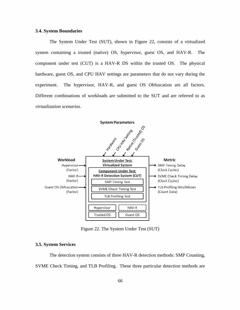
66
3.4. System Boundaries
The System Under Test (SUT), shown in Figure 22, consists of a virtualized
system containing a trusted (native) OS, hypervisor, guest OS, and HAV-R. The
component under test (CUT) is a HAV-R DS within the trusted OS. The physical
hardware, guest OS, and CPU HAV settings are parameters that do not vary during the
experiment. The hypervisor, HAV-R, and guest OS Obfuscation are all factors.
Different combinations of workloads are submitted to the SUT and are referred to as
virtualization scenarios.
Figure 22. The System Under Test (SUT)
3.5. System Services
The detection system consists of three HAV-R detection methods: SMP Counting,
SVME Check Timing, and TLB Profiling. These three particular detection methods are
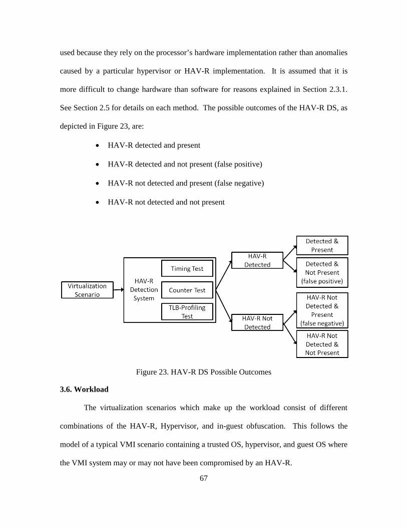
67
used because they rely on the processor’s hardware implementation rather than anomalies
caused by a particular hypervisor or HAV-R implementation. It is assumed that it is
more difficult to change hardware than software for reasons explained in Section 2.3.1.
See Section 2.5 for details on each method. The possible outcomes of the HAV-R DS, as
depicted in Figure 23, are:
• HAV-R detected and present
• HAV-R detected and not present (false positive)
• HAV-R not detected and present (false negative)
• HAV-R not detected and not present
Figure 23. HAV-R DS Possible Outcomes
3.6. Workload
The virtualization scenarios which make up the workload consist of different
combinations of the HAV-R, Hypervisor, and in-guest obfuscation. This follows the
model of a typical VMI scenario containing a trusted OS, hypervisor, and guest OS where
the VMI system may or may not have been compromised by an HAV-R.
68
3.7. Performance Metrics
Detection of HAV-R is based on the HAV-R’s impact on the performance of the
system. This performance is measured using clock cycles and by counting the number of
TLB hits and misses. The individual experiments are evaluated based on a binary metric,
the ability of the HAV-R DS to successfully detect the HAV-R. False positive and false
negative results are considered failures while accurate detection, both detected and not
detected, is considered success.
3.8. System Parameters
The system parameters include the hardware, trusted OS, guest OS, CPU HAV
Setting, hypervisor, HAV-R, and in-guest obfuscation agent (guest obfuscation - GO).
Factors which are also parameters are discussed in Section 3.9.
3.8.1. Hardware
The hardware used for experimentation consists of a HP Compaq DC5850
Microtower with the following specifications:
• AMD Athlon 64 X2 7750 Dual Core 2.70 GHz Processor, Black Edition
• 786F6 BIOS version 01.09
• 4 x 1 GB PC2-6400 RAM
• 232 GB hard drive
The processor includes AMD Virtualization Technology which provides Hardware
Assisted Virtualization (HAV) operation. The overall system is designed to meet the
minimum requirements for simultaneous support of the selected trusted OS, hypervisors,
guest OSs, and HAV-R’s considered for this research.
69
3.8.2. Trusted (Native) OS
The trusted OS is the lowest level OS within the nested virtualized system. The
trusted OS used in this research is 64-bit Microsoft Windows Vista Business version
6.0.6000 Build 6000 (no service pack). Vista is chosen for its compatibility with BluePill.
All virtualization scenarios use Vista as the trusted OS. Note that the trusted OS could
also be called the host OS or native OS however, since it becomes virtualized during
many of the experiments, it is referred to as the trusted OS to avoid confusion between it
and the original guest OS within the original virtualized system.
3.8.3. Guest OS
Windows 7 Professional, 64-bit, Service Pack 1 is the guest OS for all
experiments as it represents a current, widely-used commercial OS and a likely target for
attackers.
3.8.4. CPU HAV Setting
The CPU HAV setting is enabled for all experiments, regardless of hypervisor
requirements. This is because HAV must be enabled for installation of the HAV-R.
3.9. Factors
Factors are parameters that are varied between levels and submitted to the SUT.
The results of varying these factors are measured by the performance metrics. A
summary of factors and corresponding levels used in this study is provided in Table 1.
The factors are the hypervisor, HAV-R, and in-guest obfuscation agent. Types within the
hypervisor and HAV-R factor categories are mutually exclusive, e.g. BluePill or ESXi
can be on, but not both simultaneously.
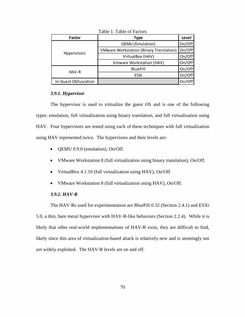
70
Table 1. Table of Factors
3.9.1. Hypervisor
The hypervisor is used to virtualize the guest OS and is one of the following
types: emulation, full virtualization using binary translation, and full virtualization using
HAV. Four hypervisors are tested using each of these techniques with full virtualization
using HAV represented twice. The hypervisors and their levels are:
• QEMU 0.9.0 (emulation), On/Off.
• VMware Workstation 8 (full virtualization using binary translation), On/Off.
• VirtualBox 4.1.10 (full virtualization using HAV), On/Off.
• VMware Workstation 8 (full virtualization using HAV), On/Off.
3.9.2. HAV-R
The HAV-Rs used for experimentation are BluePill 0.32 (Section 2.4.1) and ESXi
5.0, a thin, bare metal hypervisor with HAV-R-like behaviors (Section 2.2.4). While it is
likely that other real-world implementations of HAV-R exist, they are difficult to find,
likely since this area of virtualization-based attack is relatively new and is seemingly not
yet widely exploited. The HAV-R levels are on and off.
Type LevelQEMU (Emulation) On/Off
VMware Workstation (Binary Translation) On/OffVirtualBox (HAV) On/Off
Vmware Workstation (HAV) On/OffBluePill On/Off
ESXi On/OffOn/Off
Hypervisors
HAV-R
Factor
In-Guest Obfuscation
71
3.9.3. Guest Obfuscation Agent
A guest OS that is capable of installing an HAV-R beneath the trusted OS may
also attempt to hide the HAV-R by anticipating detection techniques and performing in-
guest execution of privileged instructions in order to counter HAV-R detection. This is
modeled through the inclusion of an in-guest obfuscation agent, Cloaker, which sends
randomized privileged instructions to the processor and actively changes fields in the
TLB. The guest obfuscation levels are on and off.
3.10. Evaluation Technique
The evaluation method is empirical measurement of a real system. Due to the
complexity of nested virtualized systems, this is the most practical and meaningful test
for detection of HAV-R since it provides results derived from execution within a real
system.
To evaluate the ability of the HAV-R DS to detect the presence of a HAV-R,
virtualization scenarios consisting of different combinations of factors are submitted to
the HAV-R DS and direct measurements are obtained using HyperScan. This data is
used to infer the existence of a HAV-R based on changes encountered during subsequent
measurements of the system after an initial baseline measurement is performed on a
trusted system which does not contain a HAV-R. Experiments are performed
sequentially with sufficient delay between replications such that the non-subverted
trusted system is assumed to reach a steady state with minimal variance between
experiments. For this research, 750-1000 ms is considered sufficient delay between
replications based on preliminary analysis accomplished during pilot testing
72
(see Section 3.2). There is also a delay of 10 minutes prior to execution of HyperScan for
each virtualization scenario. Pilot testing using the Windows Task Manager Performance
Monitor revealed that a delay of 5 minutes is sufficient for the system to reach a steady
state after a reboot of the system and once all required applications are running. This is
doubled to a delay of 10 minutes as a precautionary measure. Variance is expected to be
low due to the mechanical nature of the tests and the data is expected to be normally
distributed. The resulting data is analyzed using statistical analysis of variance
(ANOVA) techniques to determine if the data gathered before and after subversion are
statistically different.
To perform the experiments, the following steps are taken for each virtualization
scenario:
1. Gather performance metrics from a non-subverted VMI system
a. Configure the host machine with the trusted OS, hypervisor, and guest OS;
the guest OS will remain running and is not paused or stopped during
experimentation.
b. Install the data collection tool, HyperScan, within the trusted OS.
c. Reboot the machine and, after a wait of 10 minutes during which the
system is assumed to reach a steady state, execute HyperScan to gather
non-subverted VMI baseline data for the non-subverted VMI system.
Save the data for later analysis.
2. Gather performance metrics from the subverted VMI (SVMI) system
a. Configure the SVMI system by adding a HAV-R to the non-subverted
system resulting in a nested virtualized environment.
73
b. After a wait of 10 minutes, during which the system is assumed to reach a
steady state, execute the HyperScan to gather SVMI benchmark data for
the SVMI system. Save the data for later analysis.
3. Gather performance metrics from SVMI system with GO
a. Install and execute the GO program, Cloaker, within the guest OS; note
that the guest OS will remain running and should not be paused or stopped
during experimentation.
b. After a wait of 10 minutes, during which the system is assumed to reach a
steady state, execute HyperScan to gather SVMI with Guest Obfuscation
benchmark data for the SVMI with Guest Obfuscation system. Save the
data for later analysis.
4. Repeat steps 1-3 for each hypervisor configuration to be tested.
5. Repeat steps 1-4 for each HAV-R to be tested.
6. Upon completion, analyze the data to determine if detectable and statistically
significant delays are caused by the existence of a HAV-R. Analyze the
impact of each hypervisor and GO on HAV-R detection.
The results obtained from experimentation are validated through prior knowledge of
hypervisor and x86 architecture interaction, statistical analysis of the data, and direct
observation of the system.
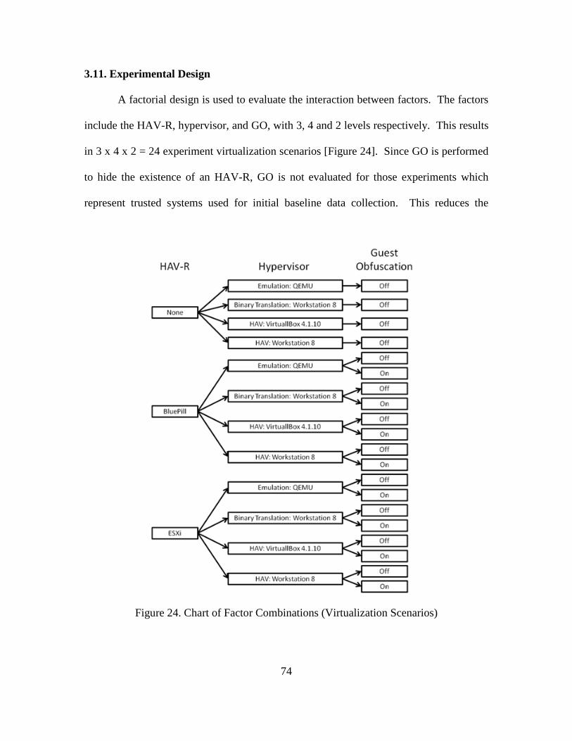
74
3.11. Experimental Design
A factorial design is used to evaluate the interaction between factors. The factors
include the HAV-R, hypervisor, and GO, with 3, 4 and 2 levels respectively. This results
in 3 x 4 x 2 = 24 experiment virtualization scenarios [Figure 24]. Since GO is performed
to hide the existence of an HAV-R, GO is not evaluated for those experiments which
represent trusted systems used for initial baseline data collection. This reduces the
Figure 24. Chart of Factor Combinations (Virtualization Scenarios)
75
number of scenarios by 4 resulting in 20 virtualization scenarios. Each of the 20
virtualization scenarios is tested using three detection techniques, and these tests are
repeated 200 times. This results in 20 * 3 * 200 = 12,000 total experiments. Consecutive
tests are performed at semi-random intervals bounded between 0.75
and 1 second inclusive. Based on pilot studies, low variance and normality are assumed
and the analysis is performed using a 95% confidence interval. Even if the data is non-
normal, the central limit theorem states that the sampling distribution is approximately
normal for large sample sizes (where the number of samples > 30). Since the average
time between tests is a fraction of a second, 200 tests are performed which provide a
relatively large number of measurements within a small amount of time.
3.12. Methodology Summary
This research effort is designed to accomplish the following goals:
• Determine if it is possible to detect HAV-Rs within a nested virtualized
environment using selected detection techniques.
• Explore how different virtualization techniques affect HAV-R detection within a
nested virtualized environment.
• Determine if in-guest obfuscation affects HAV-R detection.
To do this end, twenty virtualization scenarios are developed using three virtualization
types, two HAV-Rs, and two levels of GO. Each scenario is evaluated using three
detection techniques with 200 repetitions each. The results are statistically analyzed
using ANOVA techniques to determine if HAV-Rs are detectable within a nested
virtualized environment as well as how each factor affects HAV-R detection.
76
IV. Analysis
Twenty virtualization scenarios are tested using the three detection techniques of
SMP Counting, SVME Check Timing, and TLB Profiling (referred to as SMPCOUNT,
TIMING, and TLBHIT respectively; see Section 2.5 for a description of these detection
techniques).
During testing, it is discovered that the guest obfuscation (GO) tool, Cloaker,
causes deadlock and stop errors (the “blue screen of death”) within the trusted OS during
three of the twenty virtualization scenarios. It is observed that the failures are not
consistent with any particular factor, occurring during scenarios using both BluePill and
ESXi HAV-Rs as well as configurations using emulation and HAV hypervisors. The
failures are investigated by modifying the Cloaker software however, no solution is
identified and the cause remains undetermined. It is possible that each failure occurs due
to a unique reason and it is noted that such failures could originate within the
guest OS, trusted OS, or within the HAV-R. While data is unavailable for these three
failed virtualization scenarios, the challenges encountered underscore the complexity of
developing software designed to exploit nested virtualization.
Of sixty virtualization environment/detection technique pairs consisting of twenty
virtualization scenarios with three detection techniques each, only fifty-one experiments
are successfully performed since three scenarios using three tests each are not completed
due to Cloaker problems. The resulting data is referenced using the following naming
convention: <Hypervisor>_<VMI or SVMI>_<HAV-R (if present)>_<GO (if
present)>_<Detection Technique>. A complete list of data set names is shown in Table 2.
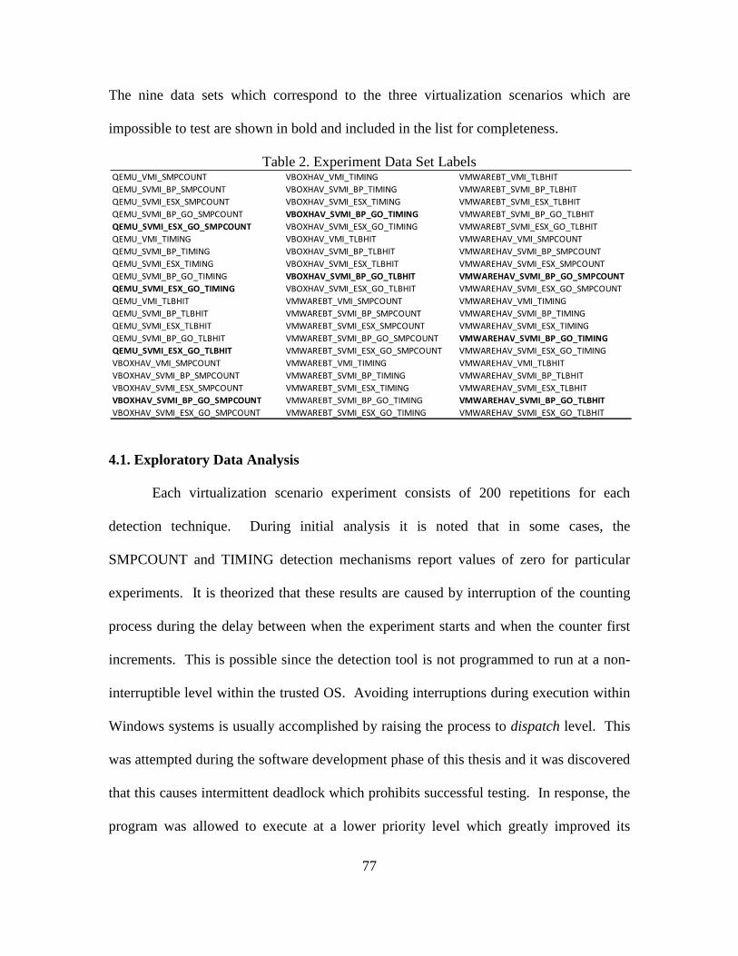
77
The nine data sets which correspond to the three virtualization scenarios which are
impossible to test are shown in bold and included in the list for completeness.
Table 2. Experiment Data Set Labels
4.1. Exploratory Data Analysis
Each virtualization scenario experiment consists of 200 repetitions for each
detection technique. During initial analysis it is noted that in some cases, the
SMPCOUNT and TIMING detection mechanisms report values of zero for particular
experiments. It is theorized that these results are caused by interruption of the counting
process during the delay between when the experiment starts and when the counter first
increments. This is possible since the detection tool is not programmed to run at a non-
interruptible level within the trusted OS. Avoiding interruptions during execution within
Windows systems is usually accomplished by raising the process to dispatch level. This
was attempted during the software development phase of this thesis and it was discovered
that this causes intermittent deadlock which prohibits successful testing. In response, the
program was allowed to execute at a lower priority level which greatly improved its
QEMU_VMI_SMPCOUNT VBOXHAV_VMI_TIMING VMWAREBT_VMI_TLBHITQEMU_SVMI_BP_SMPCOUNT VBOXHAV_SVMI_BP_TIMING VMWAREBT_SVMI_BP_TLBHITQEMU_SVMI_ESX_SMPCOUNT VBOXHAV_SVMI_ESX_TIMING VMWAREBT_SVMI_ESX_TLBHITQEMU_SVMI_BP_GO_SMPCOUNT VBOXHAV_SVMI_BP_GO_TIMING VMWAREBT_SVMI_BP_GO_TLBHITQEMU_SVMI_ESX_GO_SMPCOUNT VBOXHAV_SVMI_ESX_GO_TIMING VMWAREBT_SVMI_ESX_GO_TLBHITQEMU_VMI_TIMING VBOXHAV_VMI_TLBHIT VMWAREHAV_VMI_SMPCOUNTQEMU_SVMI_BP_TIMING VBOXHAV_SVMI_BP_TLBHIT VMWAREHAV_SVMI_BP_SMPCOUNTQEMU_SVMI_ESX_TIMING VBOXHAV_SVMI_ESX_TLBHIT VMWAREHAV_SVMI_ESX_SMPCOUNTQEMU_SVMI_BP_GO_TIMING VBOXHAV_SVMI_BP_GO_TLBHIT VMWAREHAV_SVMI_BP_GO_SMPCOUNTQEMU_SVMI_ESX_GO_TIMING VBOXHAV_SVMI_ESX_GO_TLBHIT VMWAREHAV_SVMI_ESX_GO_SMPCOUNTQEMU_VMI_TLBHIT VMWAREBT_VMI_SMPCOUNT VMWAREHAV_VMI_TIMINGQEMU_SVMI_BP_TLBHIT VMWAREBT_SVMI_BP_SMPCOUNT VMWAREHAV_SVMI_BP_TIMINGQEMU_SVMI_ESX_TLBHIT VMWAREBT_SVMI_ESX_SMPCOUNT VMWAREHAV_SVMI_ESX_TIMINGQEMU_SVMI_BP_GO_TLBHIT VMWAREBT_SVMI_BP_GO_SMPCOUNT VMWAREHAV_SVMI_BP_GO_TIMINGQEMU_SVMI_ESX_GO_TLBHIT VMWAREBT_SVMI_ESX_GO_SMPCOUNT VMWAREHAV_SVMI_ESX_GO_TIMINGVBOXHAV_VMI_SMPCOUNT VMWAREBT_VMI_TIMING VMWAREHAV_VMI_TLBHITVBOXHAV_SVMI_BP_SMPCOUNT VMWAREBT_SVMI_BP_TIMING VMWAREHAV_SVMI_BP_TLBHITVBOXHAV_SVMI_ESX_SMPCOUNT VMWAREBT_SVMI_ESX_TIMING VMWAREHAV_SVMI_ESX_TLBHITVBOXHAV_SVMI_BP_GO_SMPCOUNT VMWAREBT_SVMI_BP_GO_TIMING VMWAREHAV_SVMI_BP_GO_TLBHITVBOXHAV_SVMI_ESX_GO_SMPCOUNT VMWAREBT_SVMI_ESX_GO_TIMING VMWAREHAV_SVMI_ESX_GO_TLBHIT
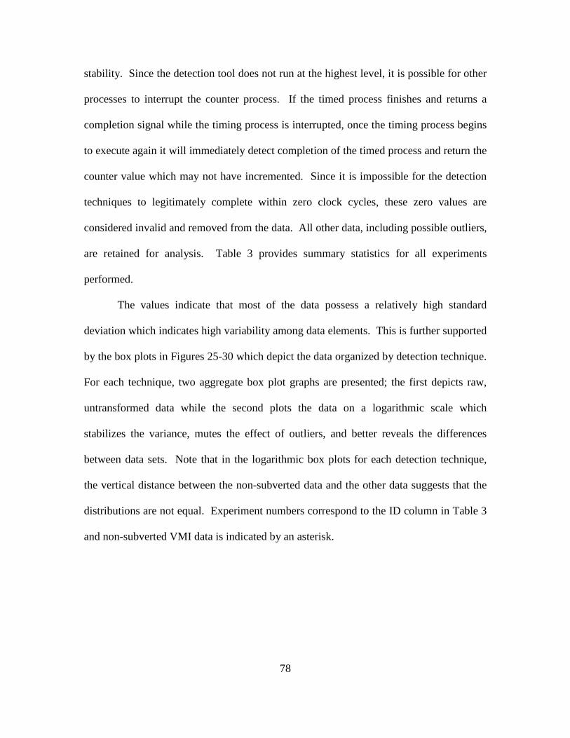
78
stability. Since the detection tool does not run at the highest level, it is possible for other
processes to interrupt the counter process. If the timed process finishes and returns a
completion signal while the timing process is interrupted, once the timing process begins
to execute again it will immediately detect completion of the timed process and return the
counter value which may not have incremented. Since it is impossible for the detection
techniques to legitimately complete within zero clock cycles, these zero values are
considered invalid and removed from the data. All other data, including possible outliers,
are retained for analysis. Table 3 provides summary statistics for all experiments
performed.
The values indicate that most of the data possess a relatively high standard
deviation which indicates high variability among data elements. This is further supported
by the box plots in Figures 25-30 which depict the data organized by detection technique.
For each technique, two aggregate box plot graphs are presented; the first depicts raw,
untransformed data while the second plots the data on a logarithmic scale which
stabilizes the variance, mutes the effect of outliers, and better reveals the differences
between data sets. Note that in the logarithmic box plots for each detection technique,
the vertical distance between the non-subverted data and the other data suggests that the
distributions are not equal. Experiment numbers correspond to the ID column in Table 3
and non-subverted VMI data is indicated by an asterisk.
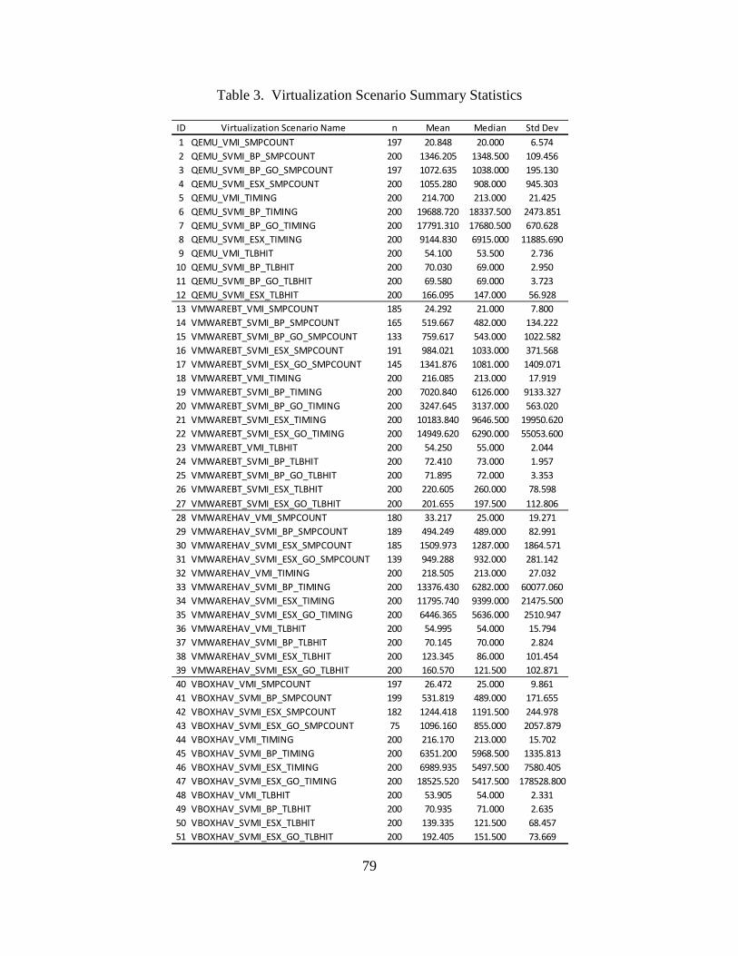
79
Table 3. Virtualization Scenario Summary Statistics
ID Virtualization Scenario Name n Mean Median Std Dev1 QEMU_VMI_SMPCOUNT 197 20.848 20.000 6.5742 QEMU_SVMI_BP_SMPCOUNT 200 1346.205 1348.500 109.4563 QEMU_SVMI_BP_GO_SMPCOUNT 197 1072.635 1038.000 195.1304 QEMU_SVMI_ESX_SMPCOUNT 200 1055.280 908.000 945.3035 QEMU_VMI_TIMING 200 214.700 213.000 21.4256 QEMU_SVMI_BP_TIMING 200 19688.720 18337.500 2473.8517 QEMU_SVMI_BP_GO_TIMING 200 17791.310 17680.500 670.6288 QEMU_SVMI_ESX_TIMING 200 9144.830 6915.000 11885.6909 QEMU_VMI_TLBHIT 200 54.100 53.500 2.736
10 QEMU_SVMI_BP_TLBHIT 200 70.030 69.000 2.95011 QEMU_SVMI_BP_GO_TLBHIT 200 69.580 69.000 3.72312 QEMU_SVMI_ESX_TLBHIT 200 166.095 147.000 56.92813 VMWAREBT_VMI_SMPCOUNT 185 24.292 21.000 7.80014 VMWAREBT_SVMI_BP_SMPCOUNT 165 519.667 482.000 134.22215 VMWAREBT_SVMI_BP_GO_SMPCOUNT 133 759.617 543.000 1022.58216 VMWAREBT_SVMI_ESX_SMPCOUNT 191 984.021 1033.000 371.56817 VMWAREBT_SVMI_ESX_GO_SMPCOUNT 145 1341.876 1081.000 1409.07118 VMWAREBT_VMI_TIMING 200 216.085 213.000 17.91919 VMWAREBT_SVMI_BP_TIMING 200 7020.840 6126.000 9133.32720 VMWAREBT_SVMI_BP_GO_TIMING 200 3247.645 3137.000 563.02021 VMWAREBT_SVMI_ESX_TIMING 200 10183.840 9646.500 19950.62022 VMWAREBT_SVMI_ESX_GO_TIMING 200 14949.620 6290.000 55053.60023 VMWAREBT_VMI_TLBHIT 200 54.250 55.000 2.04424 VMWAREBT_SVMI_BP_TLBHIT 200 72.410 73.000 1.95725 VMWAREBT_SVMI_BP_GO_TLBHIT 200 71.895 72.000 3.35326 VMWAREBT_SVMI_ESX_TLBHIT 200 220.605 260.000 78.59827 VMWAREBT_SVMI_ESX_GO_TLBHIT 200 201.655 197.500 112.80628 VMWAREHAV_VMI_SMPCOUNT 180 33.217 25.000 19.27129 VMWAREHAV_SVMI_BP_SMPCOUNT 189 494.249 489.000 82.99130 VMWAREHAV_SVMI_ESX_SMPCOUNT 185 1509.973 1287.000 1864.57131 VMWAREHAV_SVMI_ESX_GO_SMPCOUNT 139 949.288 932.000 281.14232 VMWAREHAV_VMI_TIMING 200 218.505 213.000 27.03233 VMWAREHAV_SVMI_BP_TIMING 200 13376.430 6282.000 60077.06034 VMWAREHAV_SVMI_ESX_TIMING 200 11795.740 9399.000 21475.50035 VMWAREHAV_SVMI_ESX_GO_TIMING 200 6446.365 5636.000 2510.94736 VMWAREHAV_VMI_TLBHIT 200 54.995 54.000 15.79437 VMWAREHAV_SVMI_BP_TLBHIT 200 70.145 70.000 2.82438 VMWAREHAV_SVMI_ESX_TLBHIT 200 123.345 86.000 101.45439 VMWAREHAV_SVMI_ESX_GO_TLBHIT 200 160.570 121.500 102.87140 VBOXHAV_VMI_SMPCOUNT 197 26.472 25.000 9.86141 VBOXHAV_SVMI_BP_SMPCOUNT 199 531.819 489.000 171.65542 VBOXHAV_SVMI_ESX_SMPCOUNT 182 1244.418 1191.500 244.97843 VBOXHAV_SVMI_ESX_GO_SMPCOUNT 75 1096.160 855.000 2057.87944 VBOXHAV_VMI_TIMING 200 216.170 213.000 15.70245 VBOXHAV_SVMI_BP_TIMING 200 6351.200 5968.500 1335.81346 VBOXHAV_SVMI_ESX_TIMING 200 6989.935 5497.500 7580.40547 VBOXHAV_SVMI_ESX_GO_TIMING 200 18525.520 5417.500 178528.80048 VBOXHAV_VMI_TLBHIT 200 53.905 54.000 2.33149 VBOXHAV_SVMI_BP_TLBHIT 200 70.935 71.000 2.63550 VBOXHAV_SVMI_ESX_TLBHIT 200 139.335 121.500 68.45751 VBOXHAV_SVMI_ESX_GO_TLBHIT 200 192.405 151.500 73.669
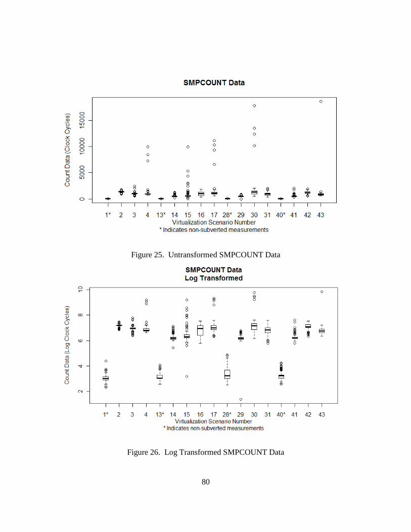
80
Figure 25. Untransformed SMPCOUNT Data
Figure 26. Log Transformed SMPCOUNT Data
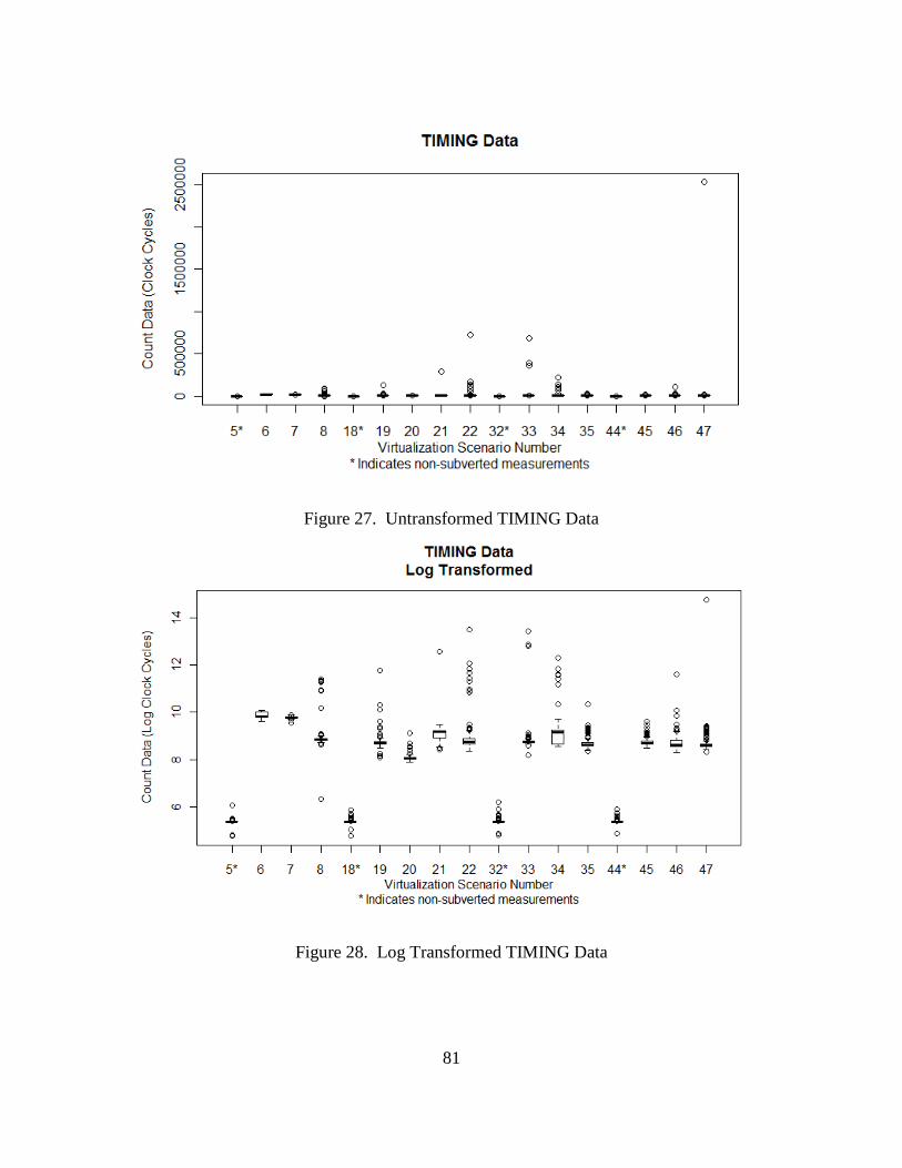
81
Figure 27. Untransformed TIMING Data
Figure 28. Log Transformed TIMING Data
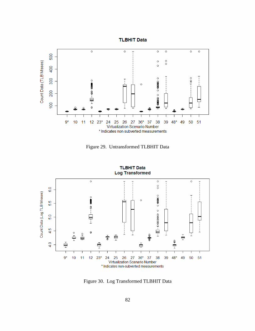
82
Figure 29. Untransformed TLBHIT Data
Figure 30. Log Transformed TLBHIT Data
83
Box plots, along with quantile quantile plots and density plots of each data set
further indicate that much of the data is highly skewed with several outliers (See
Appendix H for quantile quantile and density plots not included here). Overall, the
results appear to consist of non-normal, skewed, and occasionally long tailed data with
outliers. Such data is considered non-parametric since it cannot be assumed to be
normally distributed [GiC11]. This is surprising and invalidates earlier assumptions of
normality expressed in Chapter III. As a result, non-parametric statistical tools are
employed.
To determine if two non-parametric populations are statistically different, the null
hypothesis that they are identical is tested using the Wilcoxon rank sum test. This test is
equivalent to the Mann-Whitney U test, assumes independent ordinal observations, and is
particularly powerful for non-parametric data. It is considered by many statisticians to be
the best non-parametric test for location. In instances where the two populations are
normal, the asymptotic relative efficiency (a measure of the closeness of the selected
procedure to a notional “best possible” procedure) is 0.9550, making it robust for both
normal and non-parametric data [GiC11] [SaS05]. This is significant since some of the
experimental data used in this thesis may exhibit normality though most samples are non-
parametric. Relative to the two-sample Student’s t test, a commonly used parametric tool
mathematically equivalent to the one-way analysis of variance test for comparison of two
populations, the Wilcoxon rank-sum test has an asymptotic relative efficiency of, at
minimum, 0.864 and performs better than the t test for some non-normal distributions.
Since the t test is questionable for non-parametric data (due to its reliance on normality
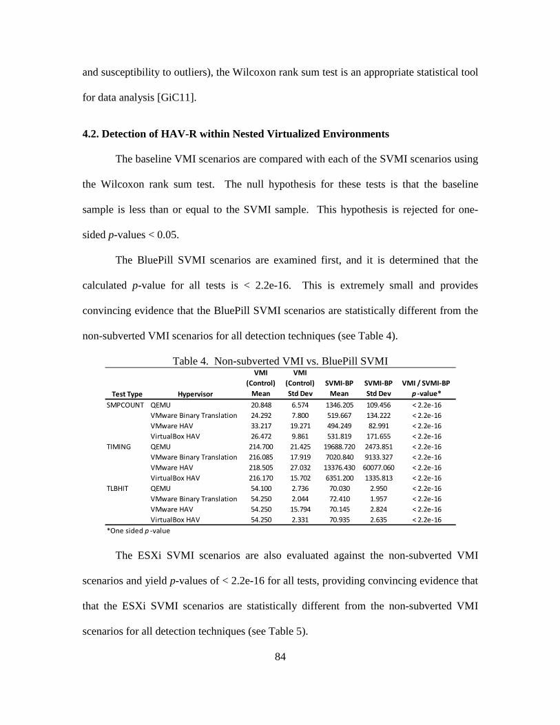
84
and susceptibility to outliers), the Wilcoxon rank sum test is an appropriate statistical tool
for data analysis [GiC11].
4.2. Detection of HAV-R within Nested Virtualized Environments
The baseline VMI scenarios are compared with each of the SVMI scenarios using
the Wilcoxon rank sum test. The null hypothesis for these tests is that the baseline
sample is less than or equal to the SVMI sample. This hypothesis is rejected for one-
sided p-values < 0.05.
The BluePill SVMI scenarios are examined first, and it is determined that the
calculated p-value for all tests is < 2.2e-16. This is extremely small and provides
convincing evidence that the BluePill SVMI scenarios are statistically different from the
non-subverted VMI scenarios for all detection techniques (see Table 4).
Table 4. Non-subverted VMI vs. BluePill SVMI
The ESXi SVMI scenarios are also evaluated against the non-subverted VMI
scenarios and yield p-values of < 2.2e-16 for all tests, providing convincing evidence that
that the ESXi SVMI scenarios are statistically different from the non-subverted VMI
scenarios for all detection techniques (see Table 5).
Test Type Hypervisor
VMI (Control)
Mean
VMI (Control)Std Dev
SVMI-BP Mean
SVMI-BP Std Dev
VMI / SVMI-BP p -value*
SMPCOUNT QEMU 20.848 6.574 1346.205 109.456 < 2.2e-16VMware Binary Translation 24.292 7.800 519.667 134.222 < 2.2e-16VMware HAV 33.217 19.271 494.249 82.991 < 2.2e-16VirtualBox HAV 26.472 9.861 531.819 171.655 < 2.2e-16
TIMING QEMU 214.700 21.425 19688.720 2473.851 < 2.2e-16VMware Binary Translation 216.085 17.919 7020.840 9133.327 < 2.2e-16VMware HAV 218.505 27.032 13376.430 60077.060 < 2.2e-16VirtualBox HAV 216.170 15.702 6351.200 1335.813 < 2.2e-16
TLBHIT QEMU 54.100 2.736 70.030 2.950 < 2.2e-16VMware Binary Translation 54.250 2.044 72.410 1.957 < 2.2e-16VMware HAV 54.250 15.794 70.145 2.824 < 2.2e-16VirtualBox HAV 54.250 2.331 70.935 2.635 < 2.2e-16
*One sided p -value
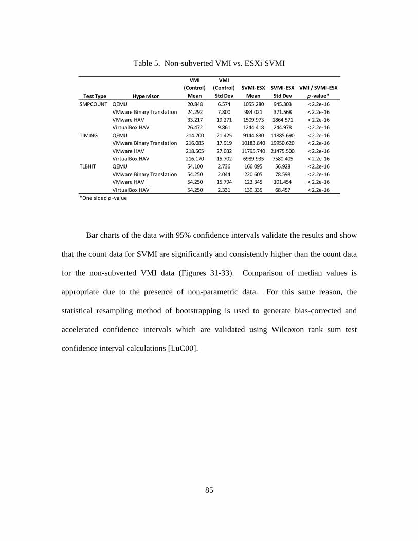
85
Table 5. Non-subverted VMI vs. ESXi SVMI
Bar charts of the data with 95% confidence intervals validate the results and show
that the count data for SVMI are significantly and consistently higher than the count data
for the non-subverted VMI data (Figures 31-33). Comparison of median values is
appropriate due to the presence of non-parametric data. For this same reason, the
statistical resampling method of bootstrapping is used to generate bias-corrected and
accelerated confidence intervals which are validated using Wilcoxon rank sum test
confidence interval calculations [LuC00].
Test Type Hypervisor
VMI (Control)
Mean
VMI (Control)Std Dev
SVMI-ESX Mean
SVMI-ESX Std Dev
VMI / SVMI-ESXp -value*
SMPCOUNT QEMU 20.848 6.574 1055.280 945.303 < 2.2e-16VMware Binary Translation 24.292 7.800 984.021 371.568 < 2.2e-16VMware HAV 33.217 19.271 1509.973 1864.571 < 2.2e-16VirtualBox HAV 26.472 9.861 1244.418 244.978 < 2.2e-16
TIMING QEMU 214.700 21.425 9144.830 11885.690 < 2.2e-16VMware Binary Translation 216.085 17.919 10183.840 19950.620 < 2.2e-16VMware HAV 218.505 27.032 11795.740 21475.500 < 2.2e-16VirtualBox HAV 216.170 15.702 6989.935 7580.405 < 2.2e-16
TLBHIT QEMU 54.100 2.736 166.095 56.928 < 2.2e-16VMware Binary Translation 54.250 2.044 220.605 78.598 < 2.2e-16VMware HAV 54.250 15.794 123.345 101.454 < 2.2e-16VirtualBox HAV 54.250 2.331 139.335 68.457 < 2.2e-16
*One sided p -value
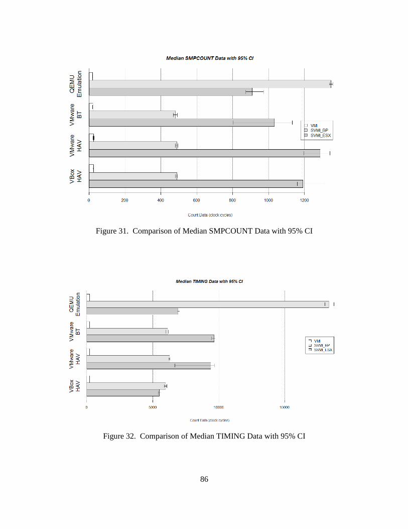
86
Figure 31. Comparison of Median SMPCOUNT Data with 95% CI
Figure 32. Comparison of Median TIMING Data with 95% CI
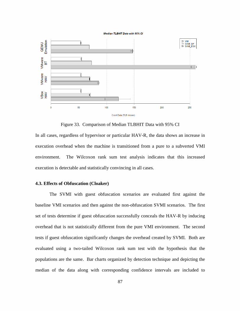
87
Figure 33. Comparison of Median TLBHIT Data with 95% CI
In all cases, regardless of hypervisor or particular HAV-R, the data shows an increase in
execution overhead when the machine is transitioned from a pure to a subverted VMI
environment. The Wilcoxon rank sum test analysis indicates that this increased
execution is detectable and statistically convincing in all cases.
4.3. Effects of Obfuscation (Cloaker)
The SVMI with guest obfuscation scenarios are evaluated first against the
baseline VMI scenarios and then against the non-obfuscation SVMI scenarios. The first
set of tests determine if guest obfuscation successfully conceals the HAV-R by inducing
overhead that is not statistically different from the pure VMI environment. The second
tests if guest obfuscation significantly changes the overhead created by SVMI. Both are
evaluated using a two-tailed Wilcoxon rank sum test with the hypothesis that the
populations are the same. Bar charts organized by detection technique and depicting the
median of the data along with corresponding confidence intervals are included to
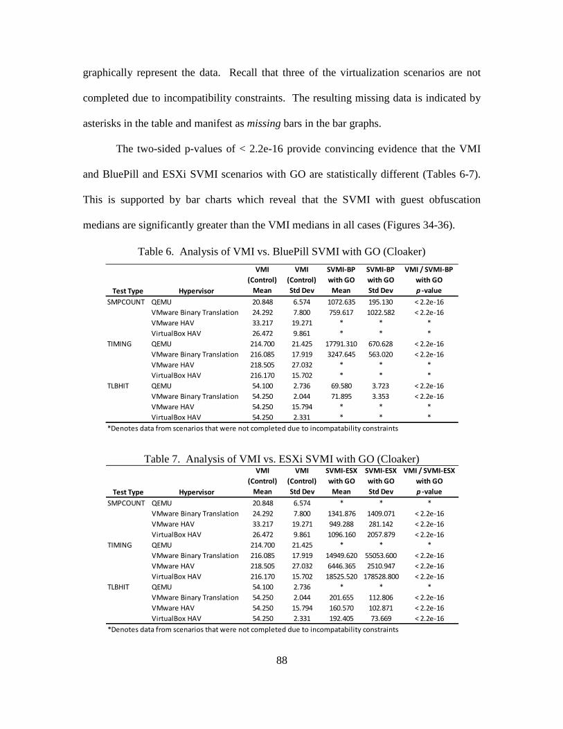
88
graphically represent the data. Recall that three of the virtualization scenarios are not
completed due to incompatibility constraints. The resulting missing data is indicated by
asterisks in the table and manifest as missing bars in the bar graphs.
The two-sided p-values of < 2.2e-16 provide convincing evidence that the VMI
and BluePill and ESXi SVMI scenarios with GO are statistically different (Tables 6-7).
This is supported by bar charts which reveal that the SVMI with guest obfuscation
medians are significantly greater than the VMI medians in all cases (Figures 34-36).
Table 6. Analysis of VMI vs. BluePill SVMI with GO (Cloaker)
Table 7. Analysis of VMI vs. ESXi SVMI with GO (Cloaker)
Test Type Hypervisor
VMI (Control)
Mean
VMI (Control)Std Dev
SVMI-BP with GO
Mean
SVMI-BPwith GO Std Dev
VMI / SVMI-BPwith GOp -value
SMPCOUNT QEMU 20.848 6.574 1072.635 195.130 < 2.2e-16VMware Binary Translation 24.292 7.800 759.617 1022.582 < 2.2e-16VMware HAV 33.217 19.271 * * *VirtualBox HAV 26.472 9.861 * * *
TIMING QEMU 214.700 21.425 17791.310 670.628 < 2.2e-16VMware Binary Translation 216.085 17.919 3247.645 563.020 < 2.2e-16VMware HAV 218.505 27.032 * * *VirtualBox HAV 216.170 15.702 * * *
TLBHIT QEMU 54.100 2.736 69.580 3.723 < 2.2e-16VMware Binary Translation 54.250 2.044 71.895 3.353 < 2.2e-16VMware HAV 54.250 15.794 * * *VirtualBox HAV 54.250 2.331 * * *
*Denotes data from scenarios that were not completed due to incompatability constraints
Test Type Hypervisor
VMI (Control)
Mean
VMI (Control)Std Dev
SVMI-ESX with GO
Mean
SVMI-ESXwith GO Std Dev
VMI / SVMI-ESXwith GOp -value
SMPCOUNT QEMU 20.848 6.574 * * *VMware Binary Translation 24.292 7.800 1341.876 1409.071 < 2.2e-16VMware HAV 33.217 19.271 949.288 281.142 < 2.2e-16VirtualBox HAV 26.472 9.861 1096.160 2057.879 < 2.2e-16
TIMING QEMU 214.700 21.425 * * *VMware Binary Translation 216.085 17.919 14949.620 55053.600 < 2.2e-16VMware HAV 218.505 27.032 6446.365 2510.947 < 2.2e-16VirtualBox HAV 216.170 15.702 18525.520 178528.800 < 2.2e-16
TLBHIT QEMU 54.100 2.736 * * *VMware Binary Translation 54.250 2.044 201.655 112.806 < 2.2e-16VMware HAV 54.250 15.794 160.570 102.871 < 2.2e-16VirtualBox HAV 54.250 2.331 192.405 73.669 < 2.2e-16
*Denotes data from scenarios that were not completed due to incompatability constraints
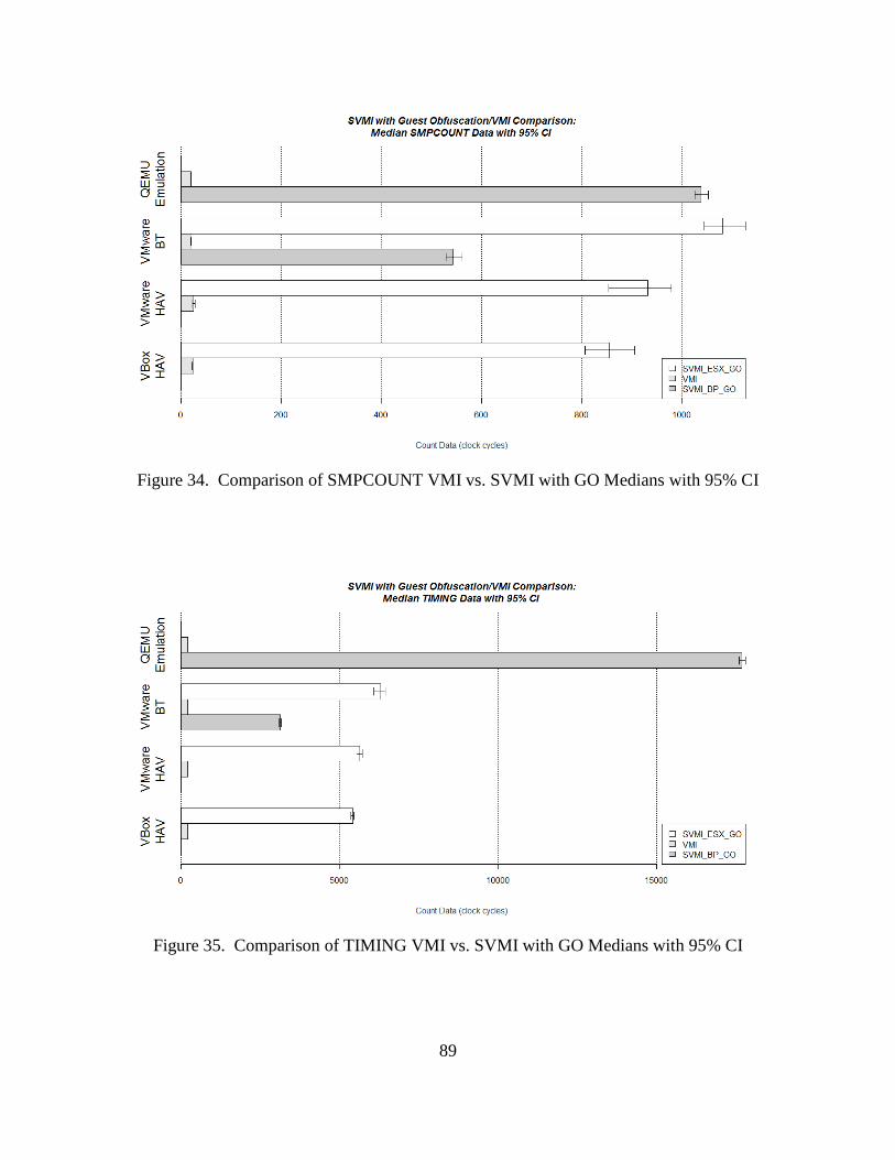
89
Figure 34. Comparison of SMPCOUNT VMI vs. SVMI with GO Medians with 95% CI
Figure 35. Comparison of TIMING VMI vs. SVMI with GO Medians with 95% CI
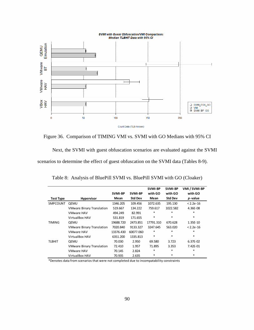
90
Figure 36. Comparison of TIMING VMI vs. SVMI with GO Medians with 95% CI
Next, the SVMI with guest obfuscation scenarios are evaluated against the SVMI
scenarios to determine the effect of guest obfuscation on the SVMI data (Tables 8-9).
Table 8: Analysis of BluePill SVMI vs. BluePill SVMI with GO (Cloaker)
Test Type HypervisorSVMI-BP
MeanSVMI-BP Std Dev
SVMI-BP with GO
Mean
SVMI-BPwith GO Std Dev
VMI / SVMI-BPwith GOp -value
SMPCOUNT QEMU 1346.205 109.456 1072.635 195.130 < 2.2e-16VMware Binary Translation 519.667 134.222 759.617 1022.582 4.36E-08VMware HAV 494.249 82.991 * * *VirtualBox HAV 531.819 171.655 * * *
TIMING QEMU 19688.720 2473.851 17791.310 670.628 1.35E-10VMware Binary Translation 7020.840 9133.327 3247.645 563.020 < 2.2e-16VMware HAV 13376.430 60077.060 * * *VirtualBox HAV 6351.200 1335.813 * * *
TLBHIT QEMU 70.030 2.950 69.580 3.723 6.37E-02VMware Binary Translation 72.410 1.957 71.895 3.353 7.42E-01VMware HAV 70.145 2.824 * * *VirtualBox HAV 70.935 2.635 * * *
*Denotes data from scenarios that were not completed due to incompatability constraints
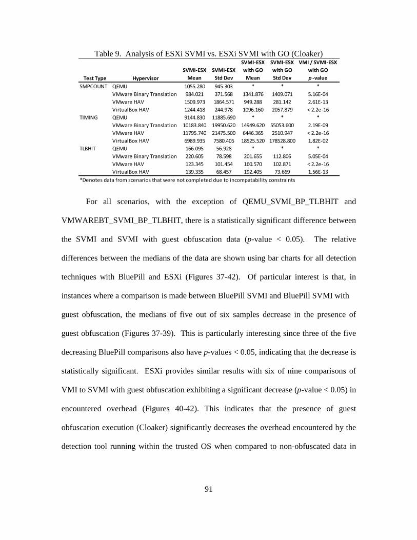
91
Table 9. Analysis of ESXi SVMI vs. ESXi SVMI with GO (Cloaker)
For all scenarios, with the exception of QEMU_SVMI_BP_TLBHIT and
VMWAREBT_SVMI_BP_TLBHIT, there is a statistically significant difference between
the SVMI and SVMI with guest obfuscation data (p-value < 0.05). The relative
differences between the medians of the data are shown using bar charts for all detection
techniques with BluePill and ESXi (Figures 37-42). Of particular interest is that, in
instances where a comparison is made between BluePill SVMI and BluePill SVMI with
guest obfuscation, the medians of five out of six samples decrease in the presence of
guest obfuscation (Figures 37-39). This is particularly interesting since three of the five
decreasing BluePill comparisons also have p-values < 0.05, indicating that the decrease is
statistically significant. ESXi provides similar results with six of nine comparisons of
VMI to SVMI with guest obfuscation exhibiting a significant decrease (p-value < 0.05) in
encountered overhead (Figures 40-42). This indicates that the presence of guest
obfuscation execution (Cloaker) significantly decreases the overhead encountered by the
detection tool running within the trusted OS when compared to non-obfuscated data in
Test Type HypervisorSVMI-ESX
MeanSVMI-ESX
Std Dev
SVMI-ESX with GO
Mean
SVMI-ESXwith GO Std Dev
VMI / SVMI-ESXwith GOp -value
SMPCOUNT QEMU 1055.280 945.303 * * *VMware Binary Translation 984.021 371.568 1341.876 1409.071 5.16E-04VMware HAV 1509.973 1864.571 949.288 281.142 2.61E-13VirtualBox HAV 1244.418 244.978 1096.160 2057.879 < 2.2e-16
TIMING QEMU 9144.830 11885.690 * * *VMware Binary Translation 10183.840 19950.620 14949.620 55053.600 2.19E-09VMware HAV 11795.740 21475.500 6446.365 2510.947 < 2.2e-16VirtualBox HAV 6989.935 7580.405 18525.520 178528.800 1.82E-02
TLBHIT QEMU 166.095 56.928 * * *VMware Binary Translation 220.605 78.598 201.655 112.806 5.05E-04VMware HAV 123.345 101.454 160.570 102.871 < 2.2e-16VirtualBox HAV 139.335 68.457 192.405 73.669 1.56E-13
*Denotes data from scenarios that were not completed due to incompatability constraints
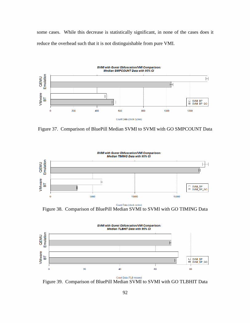
92
some cases. While this decrease is statistically significant, in none of the cases does it
reduce the overhead such that it is not distinguishable from pure VMI.
Figure 37. Comparison of BluePill Median SVMI to SVMI with GO SMPCOUNT Data
Figure 38. Comparison of BluePill Median SVMI to SVMI with GO TIMING Data
Figure 39. Comparison of BluePill Median SVMI to SVMI with GO TLBHIT Data
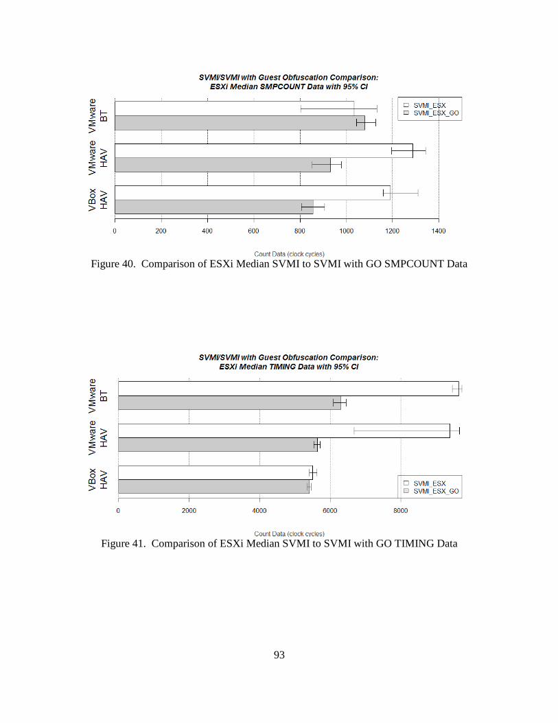
93
Figure 40. Comparison of ESXi Median SVMI to SVMI with GO SMPCOUNT Data
Figure 41. Comparison of ESXi Median SVMI to SVMI with GO TIMING Data
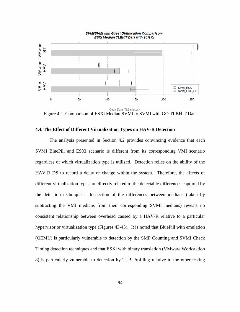
94
Figure 42. Comparison of ESXi Median SVMI to SVMI with GO TLBHIT Data
4.4. The Effect of Different Virtualization Types on HAV-R Detection
The analysis presented in Section 4.2 provides convincing evidence that each
SVMI BluePill and ESXi scenario is different from its corresponding VMI scenario
regardless of which virtualization type is utilized. Detection relies on the ability of the
HAV-R DS to record a delay or change within the system. Therefore, the effects of
different virtualization types are directly related to the detectable differences captured by
the detection techniques. Inspection of the differences between medians (taken by
subtracting the VMI medians from their corresponding SVMI medians) reveals no
consistent relationship between overhead caused by a HAV-R relative to a particular
hypervisor or virtualization type (Figures 43-45). It is noted that BluePill with emulation
(QEMU) is particularly vulnerable to detection by the SMP Counting and SVMI Check
Timing detection techniques and that ESXi with binary translation (VMware Workstation
8) is particularly vulnerable to detection by TLB Profiling relative to the other testing
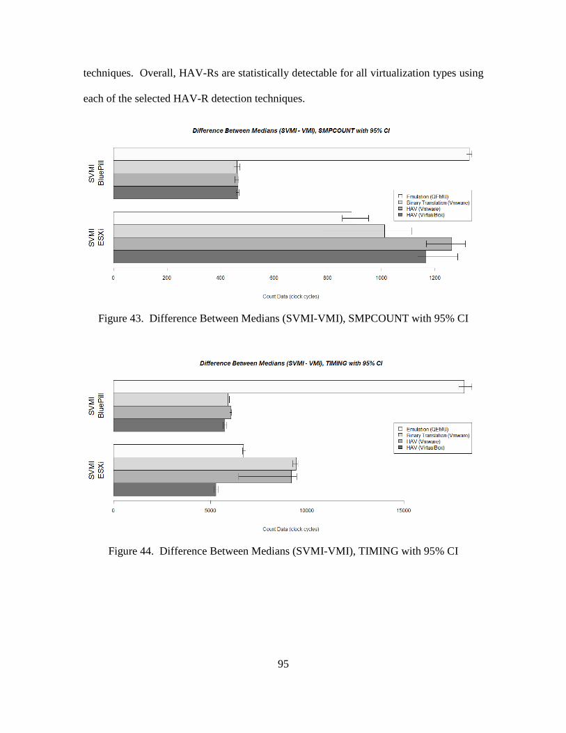
95
techniques. Overall, HAV-Rs are statistically detectable for all virtualization types using
each of the selected HAV-R detection techniques.
Figure 43. Difference Between Medians (SVMI-VMI), SMPCOUNT with 95% CI
Figure 44. Difference Between Medians (SVMI-VMI), TIMING with 95% CI
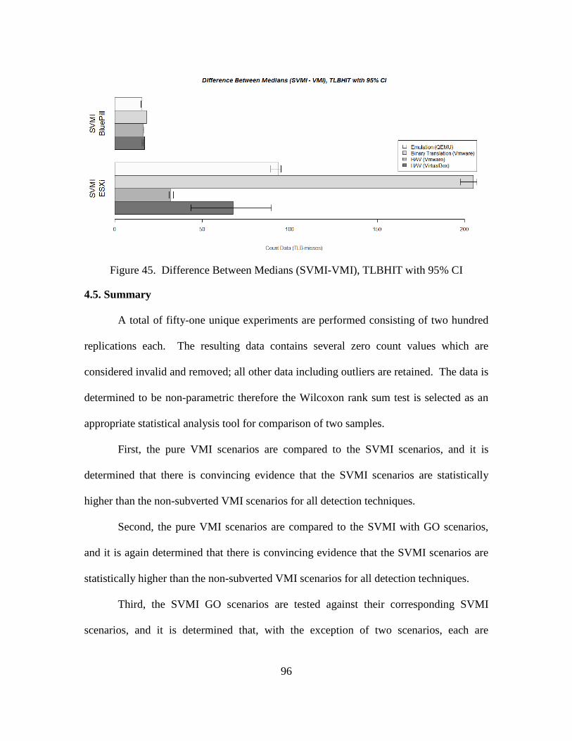
96
Figure 45. Difference Between Medians (SVMI-VMI), TLBHIT with 95% CI
4.5. Summary
A total of fifty-one unique experiments are performed consisting of two hundred
replications each. The resulting data contains several zero count values which are
considered invalid and removed; all other data including outliers are retained. The data is
determined to be non-parametric therefore the Wilcoxon rank sum test is selected as an
appropriate statistical analysis tool for comparison of two samples.
First, the pure VMI scenarios are compared to the SVMI scenarios, and it is
determined that there is convincing evidence that the SVMI scenarios are statistically
higher than the non-subverted VMI scenarios for all detection techniques.
Second, the pure VMI scenarios are compared to the SVMI with GO scenarios,
and it is again determined that there is convincing evidence that the SVMI scenarios are
statistically higher than the non-subverted VMI scenarios for all detection techniques.
Third, the SVMI GO scenarios are tested against their corresponding SVMI
scenarios, and it is determined that, with the exception of two scenarios, each are
97
statistically significantly different. It is noted that for many of the scenarios, the impact
of SVMI with guest obfuscation is a statistically significant decrease in encountered
overhead. This indicates that the presence of in-guest obfuscation significantly decreases
the overhead encountered by the detection tool running within the trusted OS when
compared to non-obfuscated data in some cases. In no cases does this obfuscate the
existence of HAV-R.
Fourth, the effect of different virtualization types on HAV-R detection is
evaluated, and it is observed that no virtualization type significantly impacted the ability
of the detection techniques to determine the existence of HAV-Rs.
Finally, it is noted that BluePill within a nested virtualized environment using
emulation is particularly susceptible to detection by the SMP Counting and SVME Check
Timing detection techniques, and that ESXi within a nested virtualized environment
using binary translation is particularly susceptible to detection by TLB Profiling.
98
V. Conclusions
This chapter provides a summary of key findings and recommendations for future
work. Section 5.1 contains an executive summary of the results, Section 5.2 gives
recommendations for future research, and Section 5.3 provides concluding remarks.
5.1. Results
This research examines the detection of hardware-assisted hypervisor rootkits
(HAV-R) within nested virtual environments. It specifically examines the effectiveness
of the three detection techniques of SMP Counting, SVME Check Timing, and TLB
Profiling against detection of two notional HAV-Rs within environments using three
types of virtualization: emulation, binary translation full virtualization, and hardware-
assisted full virtualization. The nested virtual environments use 64-bit Windows Vista
Business as the native OS and 64-bit Windows 7 Professional as the guest OS. The
hypervisors are QEMU, VMware, and VirtualBox.
It was originally hypothesized that the overhead caused by a pre-existing, trusted
hypervisor is sufficient to obfuscate the existence of a HAV-R and that, in cases where
the HAV-R is detectable, deliberate execution of privileged instructions within the guest
OS is sufficient to obscure the HAV-R. The research goals specifically addressed by this
research and their corresponding findings are as follows:
1. Is it possible to detect HAV-R within a nested virtualized environment
using selected detection techniques? Yes, for all nested virtualized
environments examined, a difference in overhead is experienced during
99
execution of the HAV-Rs which is statistically significant and greater than the
overhead experienced within the non-subverted virtualized environments.
2. Do different virtualization types significantly affect HAV-R detection
using the selected detection techniques? No, of the three virtualization types
evaluated (emulation, full virtualization using binary translation, and full
virtualization using HAV) no significant difference in detectability is
observed. In all cases, the difference in overhead experienced during
execution of the HAV-R is statistically significant and provided convincing
evidence of the presence of a HAV-R. It is observed that within nested
virtualized environments using emulation, the HAV-R BluePill seems
particularly susceptible to detection by the SMP Counting and SVME Check
Timing detection techniques. Furthermore, within a nested virtualized
environment using binary translation full virtualization, the HAV-R ESXi
seems particularly susceptible to detection by TLB Profiling. These are
relative increases in detectability defined as the difference in overhead before
and after execution of the HAV-R and do not change the fact that the HAV-Rs
are detected in all cases.
3. What is the effectiveness of in-guest execution designed to obfuscate the
existence of a HAV-R? The chosen obfuscation technique, a variant of the
detection tool which is intended to compete for processor resources, fails to
successfully obfuscate the overhead caused by the HAV-R in all cases. In
100
nine of fifteen cases the overhead experienced during execution of a HAV-R
is statistically lowered during obfuscation execution. At no time is this
significant enough to obfuscate the HAV-R for the cases examined however,
these results indicate that obfuscation efforts within the guest can have a
dampening effect on the overall overhead experienced when a HAV-R is
present.
The findings disprove the original hypothesis that overhead caused by a pre-existing,
trusted hypervisor is sufficient to obfuscate the existence of a HAV-R and that, in cases
where the HAV-R is detectable, deliberate execution of privileged instructions within the
guest OS is sufficient to obscure the HAV-R. To the contrary, the results indicate that in
cases when emulation, full virtualization using binary translation, or full virtualization
using HAV are used as the hypervisor, the presence of BluePill and ESXi are statistically
detectable and that in-guest obfuscation does not successfully obfuscate the existence of
the HAV-R.
5.2. Future Work
The following items remain unresolved and are suggested for future work:
• Explore the effect of guest obfuscation to determine why, in some scenarios, it
causes a statistically significant reduction in overhead encountered by the
detection tool. Determine if there are situations where this significant
reduction in overhead could result in successful HAV-R obfuscation.
101
• Evaluate the HAV-R detection system against HAV-R detection within nested
virtualized environments using a paravirtualization hypervisor, such as Xen.
This was not accomplished during this research due to incompatibility
between BluePill, which is designed for Windows systems, and open-source
systems required for paravirtualization.
• Explore the functionality of registers which are poorly documented but
included as extended functionality in HAV-enabled processors. Identify ways
to exploit these registers in the form of new or modified hypervisor and
HAV-R detection techniques.
• Integrate the statistical tests used for detection directly into the HyperScan
application such that it provides data collection, statistical analysis, and a
probable indication of the likeliness of HAV-R presence.
• Extend the HyperScan detection driver to support a Unix/Linux OS.
• Improve HyperScan such that it runs all tests at dispatch level. It is expected
that this will remove the preponderance of zero counts thought to result from
interruption of the counting process and will eliminate outliers thought to
result from interruption of the timed process.
• Perform analysis on current malware samples to determine if they possess a
HAV-R component.
5.3. Concluding Remarks
Hardware-assisted hypervisor rootkits are particularly interesting precisely
because they are not known to be in widespread use. It is unknown if this is because they
102
lack utility or if it is the result of a shortfall in detection mechanisms. It is also likely that
less sophisticated rootkit techniques are already overwhelmingly successful for the
majority of attacks and therefore sufficient for the requirements of most attackers. When
the Sony copy protection rootkit scandal occurred in 2005, security analyst Bruce
Schneier chastised computer security companies for failing to detect and report the
infection, noting that the malware had existed for over a year and infected more than half
a million computers without any detection, action, or comment from major security
companies. Ominously he described a deafening silence from the computer security
industry, not before, but after the malware was publically reported [Sch08].
Similarly, when Joanna Rutkowska introduced the BluePill hypervisor rootkit in
2006, there was incredible interest and controversy within the computer security
community as to its effectiveness as a potentially undetectable malware [RuT07a]. It was
soon demonstrated to be detectable and, over the past several years, academic interest in
this and similar HAV-Rs has waned. Today there is a deafening silence regarding
HAV-R research. It is unknown to what extent the HAV-R detection mechanisms
mentioned in this research are already implemented by existing anti-malware software
but it is clear that traditional techniques that detect rootkit malware within the OS kernel
are not sufficient to detect malware at the HAV hypervisor level. Word-playing off an
American colloquialism, it is said that you miss 100% of the malware that you fail to
look for. It is hoped that this thesis serves as a stepping stone towards increasingly robust
hypervisor rootkit prevention and detection techniques.
103
Appendix A. Experimentation
The following provides step-by-step instructions which explain how to set up and
configure the non-subverted VMI scenarios, subverted VMI scenarios, and subverted
VMI scenarios with in-guest obfuscation used for this research effort.
A-1. Setup the Non-Subverted VMI Scenario and Install the HyperScan Files
1. Install the host operating system, 64-bit Microsoft Windows Vista Business
version 6.0.6000 Build 6000 (no service pack).
2. Install the Hypervisor; for demonstration, VMware Workstation 8 version 8.0.0
build 471780 is used.
3. Install the Guest OS, 64-bit Windows 7 Professional, Service Pack 1.
4. Prepare both the host and the guest for test kernel-mode drivers by enabling test
signing, disabling integrity checks, and installing WinDK as explained in
Appendix B. Complete this step for both the host and guest OS. Reboot both
OSs prior to proceeding to step 5.
5. Copy the “HyperScan” and “BluePill” folders to the C:\ location of the host
machine and “tools” folder to the host machine’s desktop.
6. Copy the “Cloaker” folder to the C:\ location of the guest machine, and copy the
“Tools” folder to the guest machine’s desktop (See Figure 46).
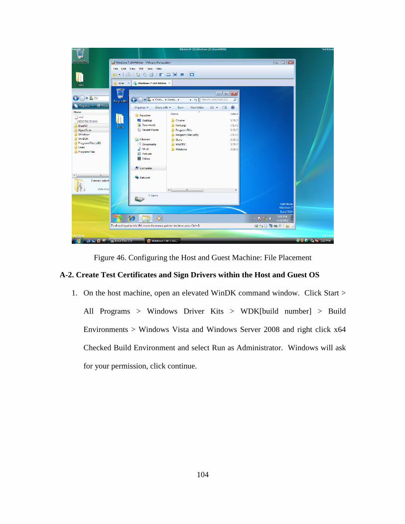
104
Figure 46. Configuring the Host and Guest Machine: File Placement
A-2. Create Test Certificates and Sign Drivers within the Host and Guest OS
1. On the host machine, open an elevated WinDK command window. Click Start >
All Programs > Windows Driver Kits > WDK[build number] > Build
Environments > Windows Vista and Windows Server 2008 and right click x64
Checked Build Environment and select Run as Administrator. Windows will ask
for your permission, click continue.
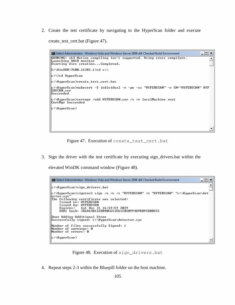
105
2. Create the test certificate by navigating to the HyperScan folder and execute
create_test_cert.bat (Figure 47).
Figure 47. Execution of create_test_cert.bat
3. Sign the driver with the test certificate by executing sign_drivers.bat within the
elevated WinDK command window (Figure 48).
Figure 48. Execution of sign_drivers.bat
4. Repeat steps 2-3 within the Bluepill folder on the host machine.
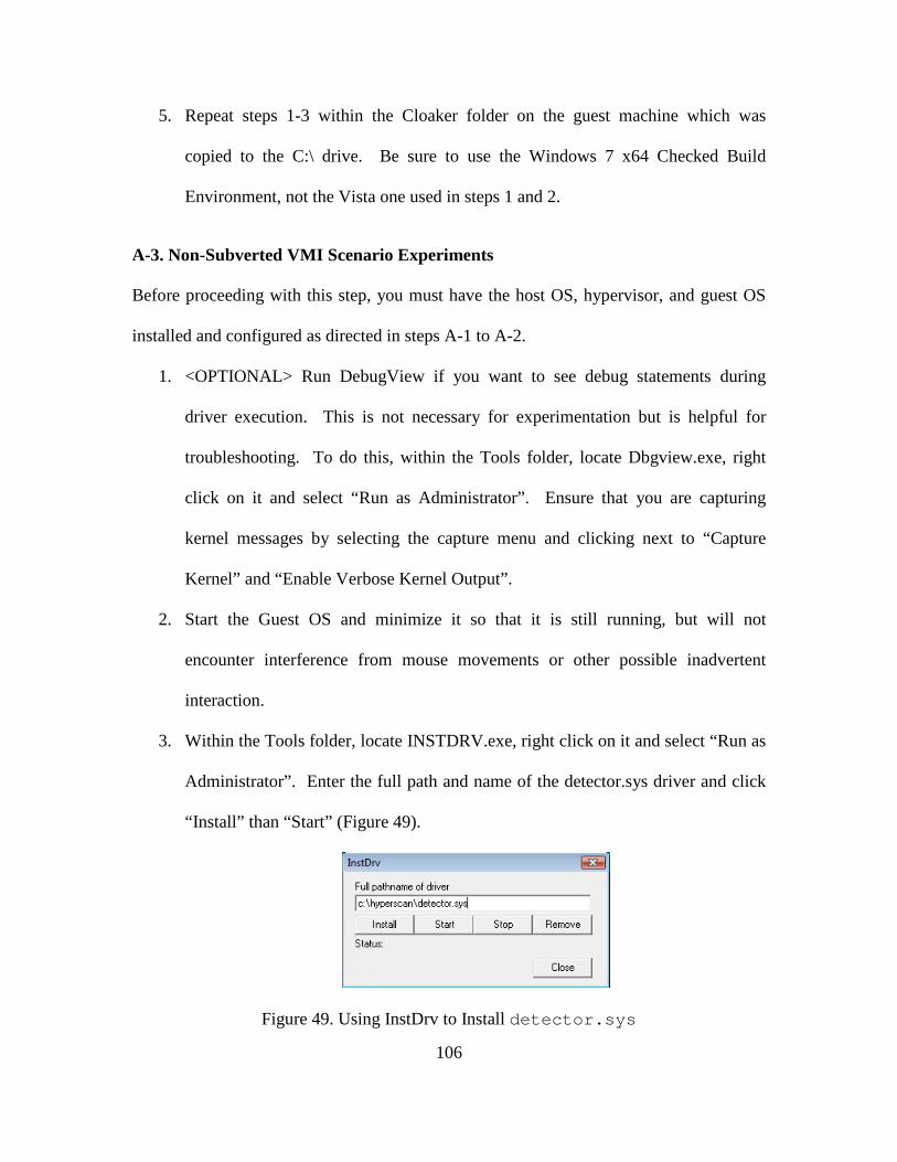
106
5. Repeat steps 1-3 within the Cloaker folder on the guest machine which was
copied to the C:\ drive. Be sure to use the Windows 7 x64 Checked Build
Environment, not the Vista one used in steps 1 and 2.
A-3. Non-Subverted VMI Scenario Experiments
Before proceeding with this step, you must have the host OS, hypervisor, and guest OS
installed and configured as directed in steps A-1 to A-2.
1. <OPTIONAL> Run DebugView if you want to see debug statements during
driver execution. This is not necessary for experimentation but is helpful for
troubleshooting. To do this, within the Tools folder, locate Dbgview.exe, right
click on it and select “Run as Administrator”. Ensure that you are capturing
kernel messages by selecting the capture menu and clicking next to “Capture
Kernel” and “Enable Verbose Kernel Output”.
2. Start the Guest OS and minimize it so that it is still running, but will not
encounter interference from mouse movements or other possible inadvertent
interaction.
3. Within the Tools folder, locate INSTDRV.exe, right click on it and select “Run as
Administrator”. Enter the full path and name of the detector.sys driver and click
“Install” than “Start” (Figure 49).
Figure 49. Using InstDrv to Install detector.sys
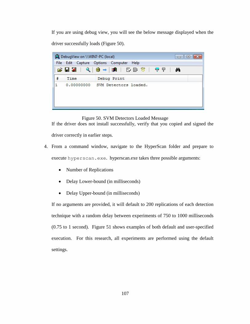
107
If you are using debug view, you will see the below message displayed when the
driver successfully loads (Figure 50).
Figure 50. SVM Detectors Loaded Message If the driver does not install successfully, verify that you copied and signed the
driver correctly in earlier steps.
4. From a command window, navigate to the HyperScan folder and prepare to
execute hyperscan.exe. hyperscan.exe takes three possible arguments:
• Number of Replications
• Delay Lower-bound (in milliseconds)
• Delay Upper-bound (in milliseconds)
If no arguments are provided, it will default to 200 replications of each detection
technique with a random delay between experiments of 750 to 1000 milliseconds
(0.75 to 1 second). Figure 51 shows examples of both default and user-specified
execution. For this research, all experiments are performed using the default
settings.
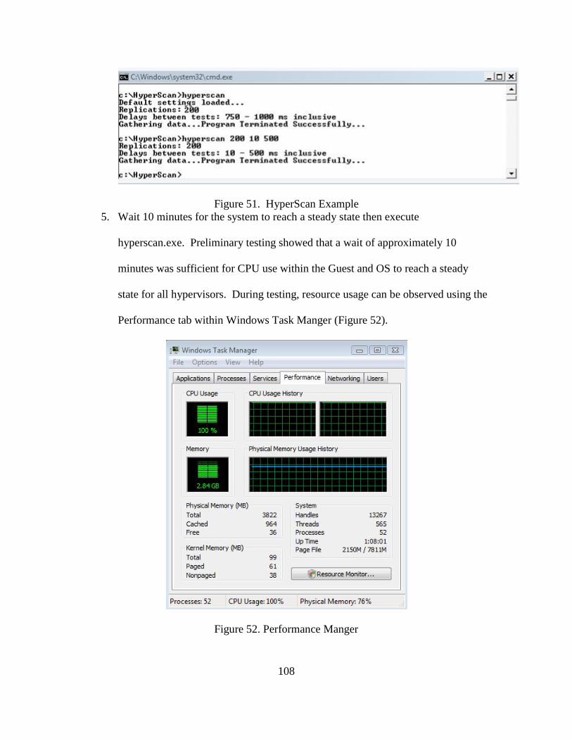
108
Figure 51. HyperScan Example 5. Wait 10 minutes for the system to reach a steady state then execute
hyperscan.exe. Preliminary testing showed that a wait of approximately 10
minutes was sufficient for CPU use within the Guest and OS to reach a steady
state for all hypervisors. During testing, resource usage can be observed using the
Performance tab within Windows Task Manger (Figure 52).
Figure 52. Performance Manger
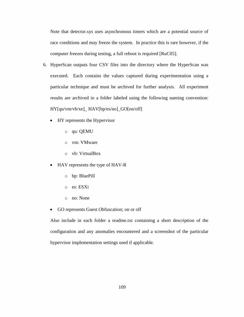
109
Note that detector.sys uses asynchronous timers which are a potential source of
race conditions and may freeze the system. In practice this is rare however, if the
computer freezes during testing, a full reboot is required [RuC05].
6. HyperScan outputs four CSV files into the directory where the HyperScan was
executed. Each contains the values captured during experimentation using a
particular technique and must be archived for further analysis. All experiment
results are archived in a folder labeled using the following naming convention:
HY[qu/vm/vb/xe]_ HAV[bp/es/no]_GO[on/off]
• HY represents the Hypervisor
o qu: QEMU
o vm: VMware
o vb: VirtualBox
• HAV represents the type of HAV-R
o bp: BluePill
o es: ESXi
o no: None
• GO represents Guest Obfuscation; on or off
Also include in each folder a readme.txt containing a short description of the
configuration and any anomalies encountered and a screenshot of the particular
hypervisor implementation settings used if applicable.
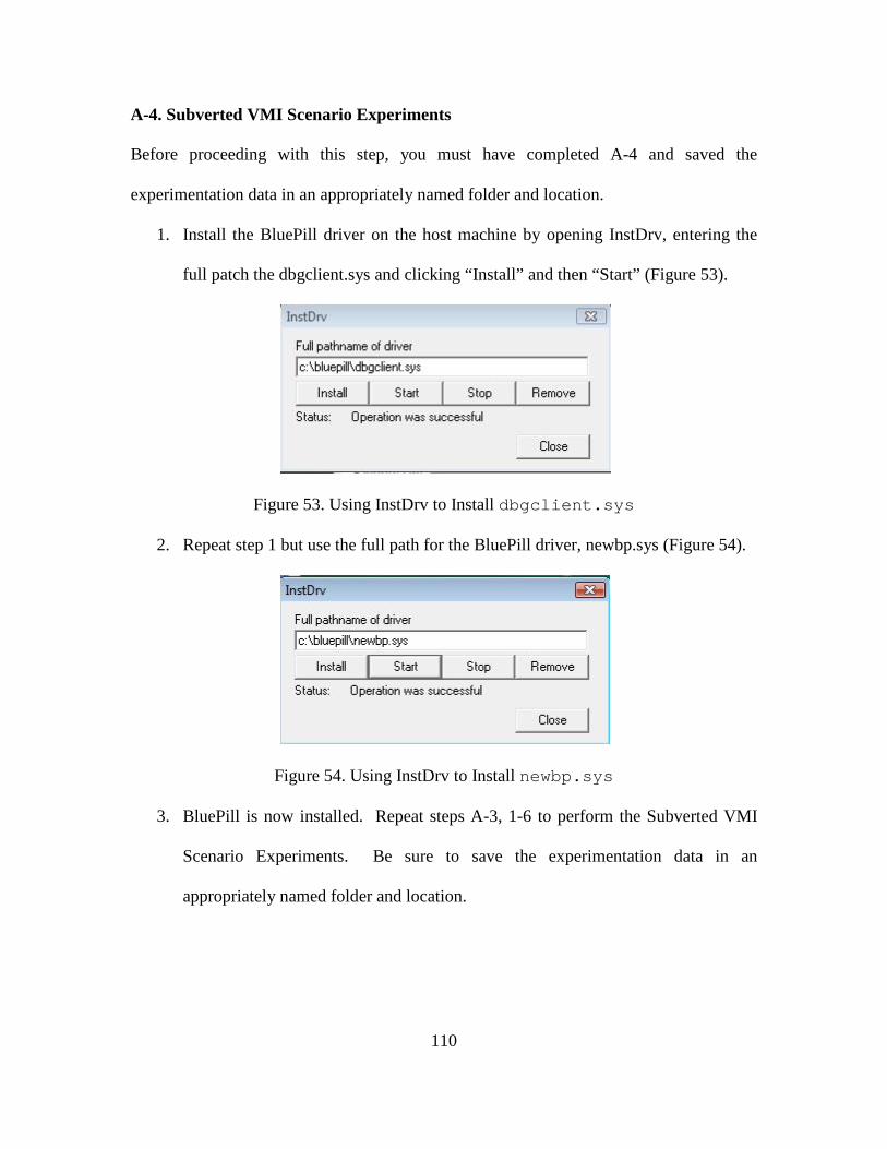
110
A-4. Subverted VMI Scenario Experiments
Before proceeding with this step, you must have completed A-4 and saved the
experimentation data in an appropriately named folder and location.
1. Install the BluePill driver on the host machine by opening InstDrv, entering the
full patch the dbgclient.sys and clicking “Install” and then “Start” (Figure 53).
Figure 53. Using InstDrv to Install dbgclient.sys
2. Repeat step 1 but use the full path for the BluePill driver, newbp.sys (Figure 54).
Figure 54. Using InstDrv to Install newbp.sys
3. BluePill is now installed. Repeat steps A-3, 1-6 to perform the Subverted VMI
Scenario Experiments. Be sure to save the experimentation data in an
appropriately named folder and location.
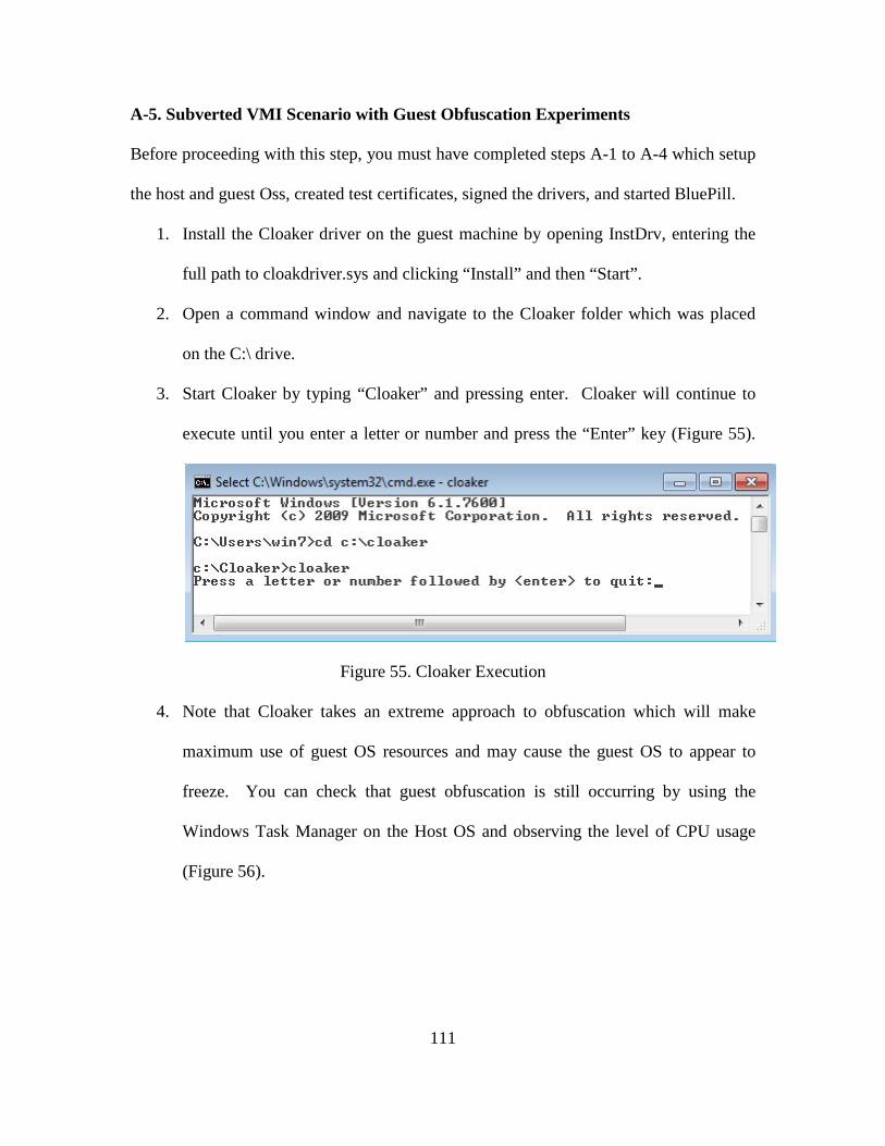
111
A-5. Subverted VMI Scenario with Guest Obfuscation Experiments
Before proceeding with this step, you must have completed steps A-1 to A-4 which setup
the host and guest Oss, created test certificates, signed the drivers, and started BluePill.
1. Install the Cloaker driver on the guest machine by opening InstDrv, entering the
full path to cloakdriver.sys and clicking “Install” and then “Start”.
2. Open a command window and navigate to the Cloaker folder which was placed
on the C:\ drive.
3. Start Cloaker by typing “Cloaker” and pressing enter. Cloaker will continue to
execute until you enter a letter or number and press the “Enter” key (Figure 55).
Figure 55. Cloaker Execution
4. Note that Cloaker takes an extreme approach to obfuscation which will make
maximum use of guest OS resources and may cause the guest OS to appear to
freeze. You can check that guest obfuscation is still occurring by using the
Windows Task Manager on the Host OS and observing the level of CPU usage
(Figure 56).
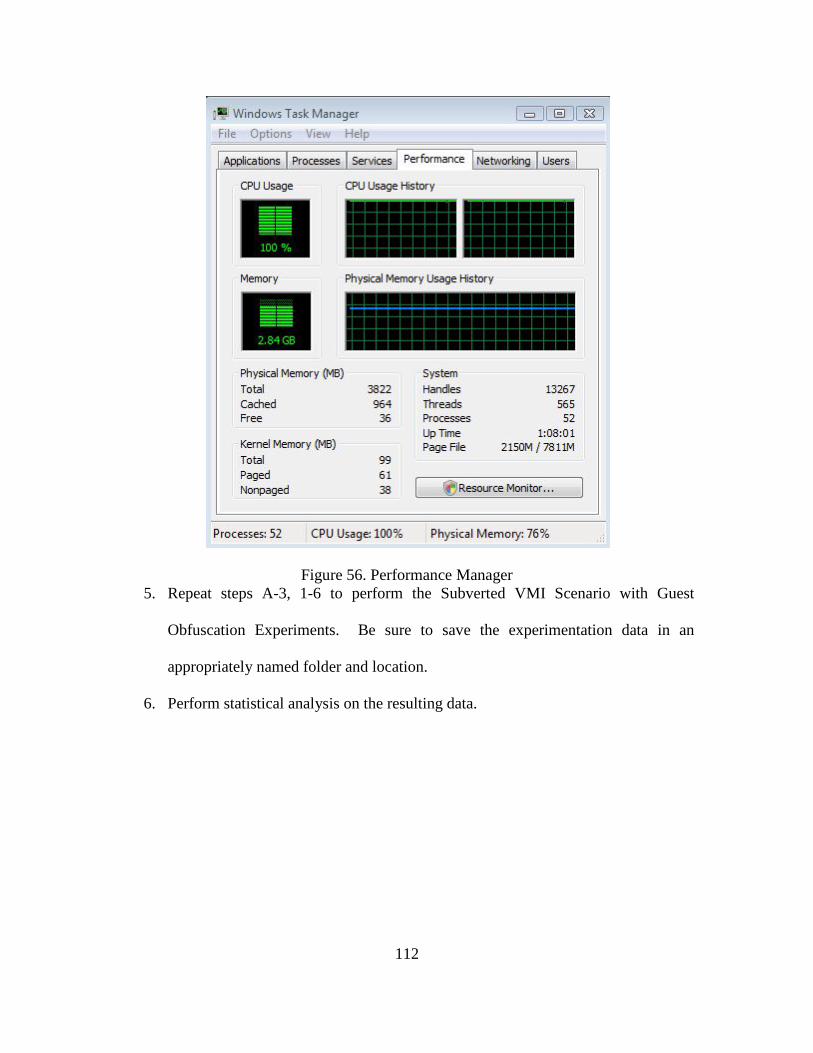
112
Figure 56. Performance Manager 5. Repeat steps A-3, 1-6 to perform the Subverted VMI Scenario with Guest
Obfuscation Experiments. Be sure to save the experimentation data in an
appropriately named folder and location.
6. Perform statistical analysis on the resulting data.
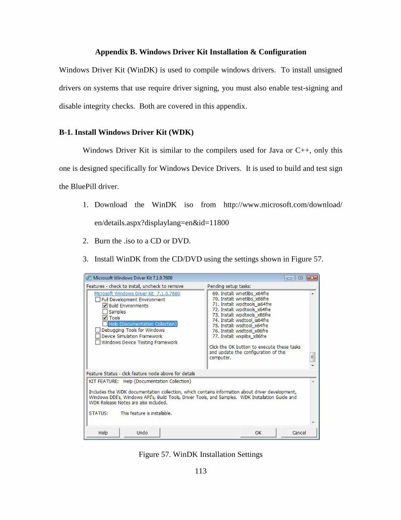
113
Appendix B. Windows Driver Kit Installation & Configuration
Windows Driver Kit (WinDK) is used to compile windows drivers. To install unsigned
drivers on systems that use require driver signing, you must also enable test-signing and
disable integrity checks. Both are covered in this appendix.
B-1. Install Windows Driver Kit (WDK)
Windows Driver Kit is similar to the compilers used for Java or C++, only this
one is designed specifically for Windows Device Drivers. It is used to build and test sign
the BluePill driver.
1. Download the WinDK iso from http://www.microsoft.com/download/
en/details.aspx?displaylang=en&id=11800
2. Burn the .iso to a CD or DVD.
3. Install WinDK from the CD/DVD using the settings shown in Figure 57.
Figure 57. WinDK Installation Settings
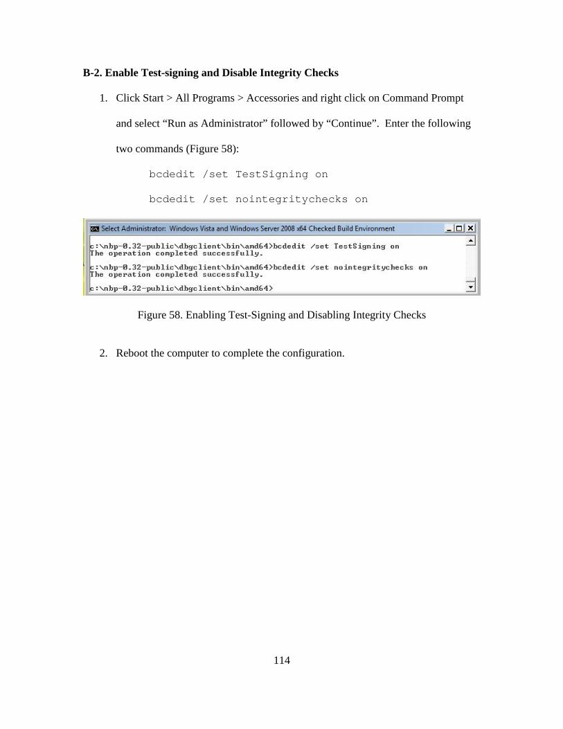
114
B-2. Enable Test-signing and Disable Integrity Checks
1. Click Start > All Programs > Accessories and right click on Command Prompt
and select “Run as Administrator” followed by “Continue”. Enter the following
two commands (Figure 58):
bcdedit /set TestSigning on
bcdedit /set nointegritychecks on
Figure 58. Enabling Test-Signing and Disabling Integrity Checks
2. Reboot the computer to complete the configuration.
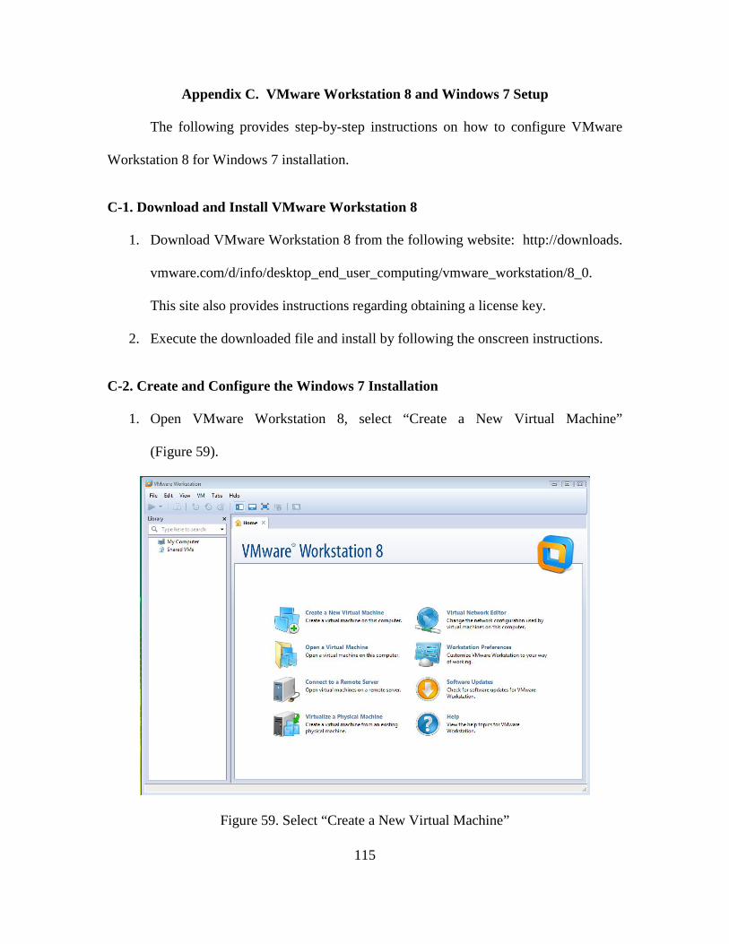
115
Appendix C. VMware Workstation 8 and Windows 7 Setup
The following provides step-by-step instructions on how to configure VMware
Workstation 8 for Windows 7 installation.
C-1. Download and Install VMware Workstation 8
1. Download VMware Workstation 8 from the following website: http://downloads.
vmware.com/d/info/desktop_end_user_computing/vmware_workstation/8_0.
This site also provides instructions regarding obtaining a license key.
2. Execute the downloaded file and install by following the onscreen instructions.
C-2. Create and Configure the Windows 7 Installation
1. Open VMware Workstation 8, select “Create a New Virtual Machine”
(Figure 59).
Figure 59. Select “Create a New Virtual Machine”
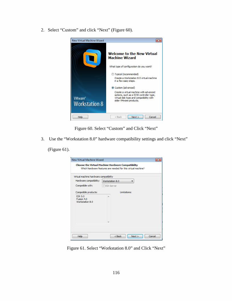
116
2. Select “Custom” and click “Next” (Figure 60).
Figure 60. Select “Custom” and Click “Next”
3. Use the “Workstation 8.0” hardware compatibility settings and click “Next”
(Figure 61).
Figure 61. Select “Workstation 8.0” and Click “Next”
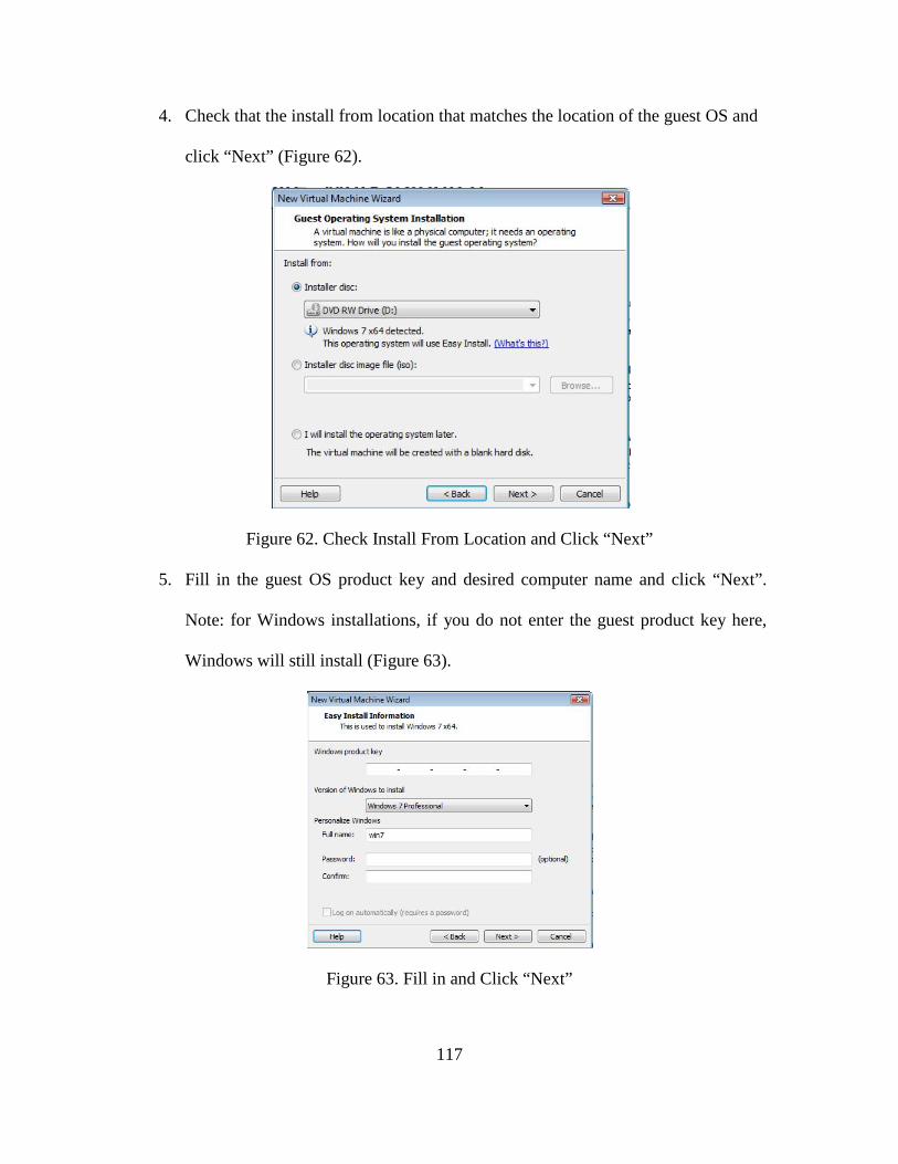
117
4. Check that the install from location that matches the location of the guest OS and
click “Next” (Figure 62).
Figure 62. Check Install From Location and Click “Next”
5. Fill in the guest OS product key and desired computer name and click “Next”.
Note: for Windows installations, if you do not enter the guest product key here,
Windows will still install (Figure 63).
Figure 63. Fill in and Click “Next”
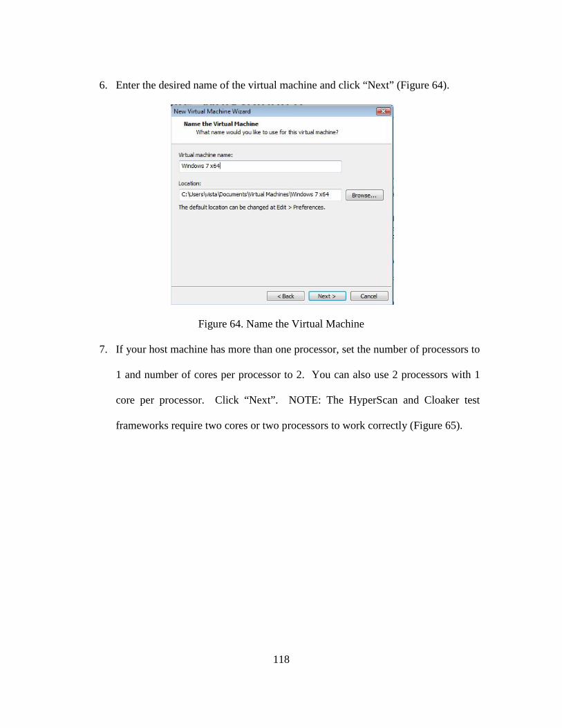
118
6. Enter the desired name of the virtual machine and click “Next” (Figure 64).
Figure 64. Name the Virtual Machine
7. If your host machine has more than one processor, set the number of processors to
1 and number of cores per processor to 2. You can also use 2 processors with 1
core per processor. Click “Next”. NOTE: The HyperScan and Cloaker test
frameworks require two cores or two processors to work correctly (Figure 65).
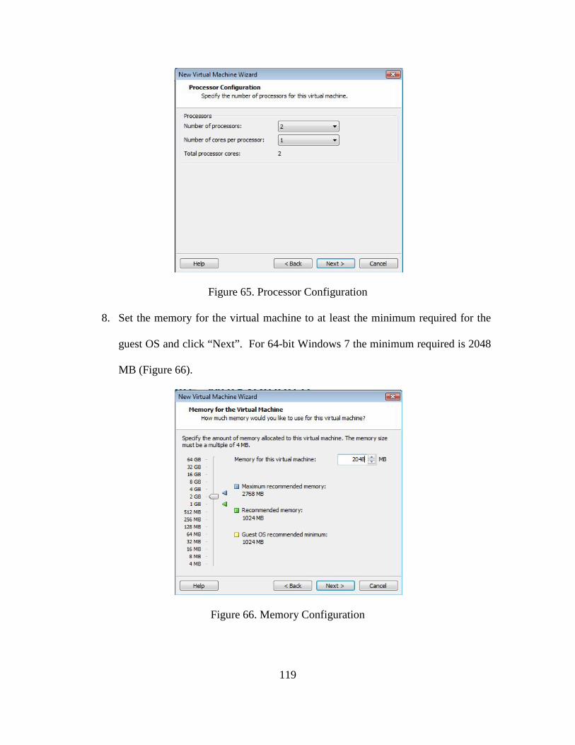
119
Figure 65. Processor Configuration
8. Set the memory for the virtual machine to at least the minimum required for the
guest OS and click “Next”. For 64-bit Windows 7 the minimum required is 2048
MB (Figure 66).
Figure 66. Memory Configuration
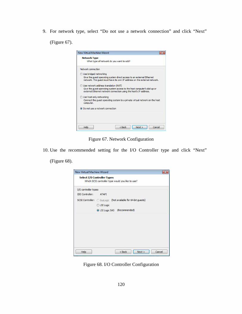
120
9. For network type, select “Do not use a network connection” and click “Next”
(Figure 67).
Figure 67. Network Configuration
10. Use the recommended setting for the I/O Controller type and click “Next”
(Figure 68).
Figure 68. I/O Controller Configuration
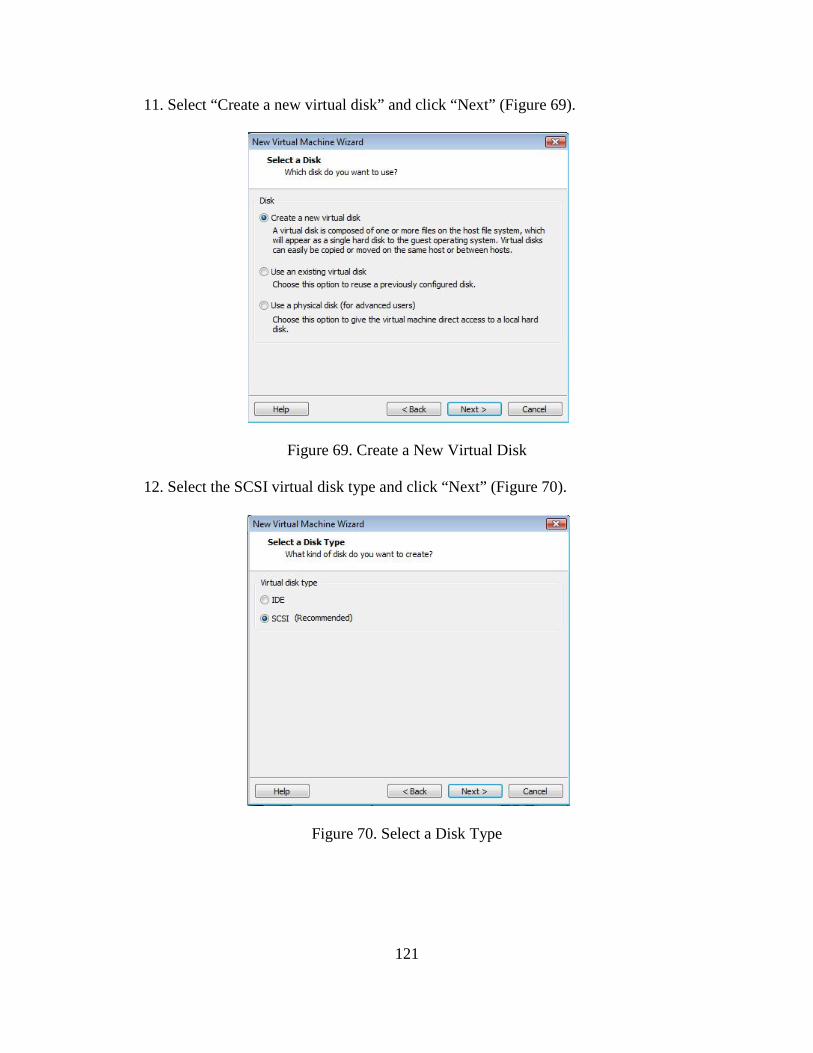
121
11. Select “Create a new virtual disk” and click “Next” (Figure 69).
Figure 69. Create a New Virtual Disk
12. Select the SCSI virtual disk type and click “Next” (Figure 70).
Figure 70. Select a Disk Type
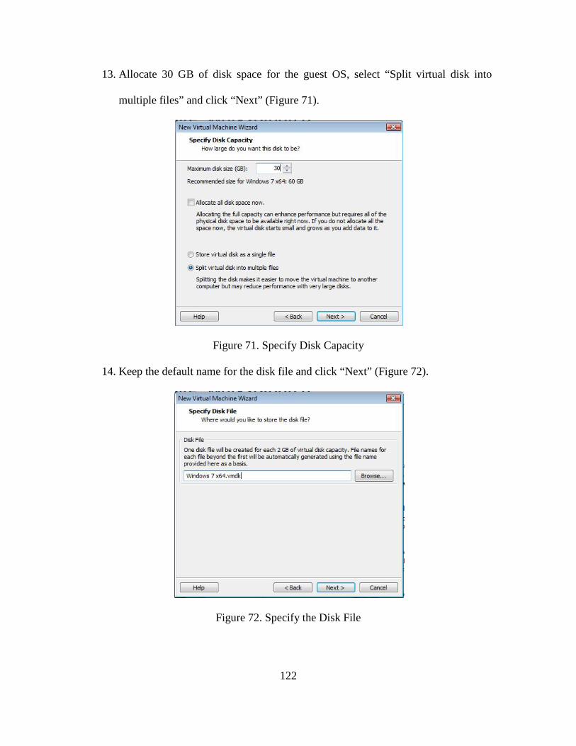
122
13. Allocate 30 GB of disk space for the guest OS, select “Split virtual disk into
multiple files” and click “Next” (Figure 71).
Figure 71. Specify Disk Capacity
14. Keep the default name for the disk file and click “Next” (Figure 72).
Figure 72. Specify the Disk File
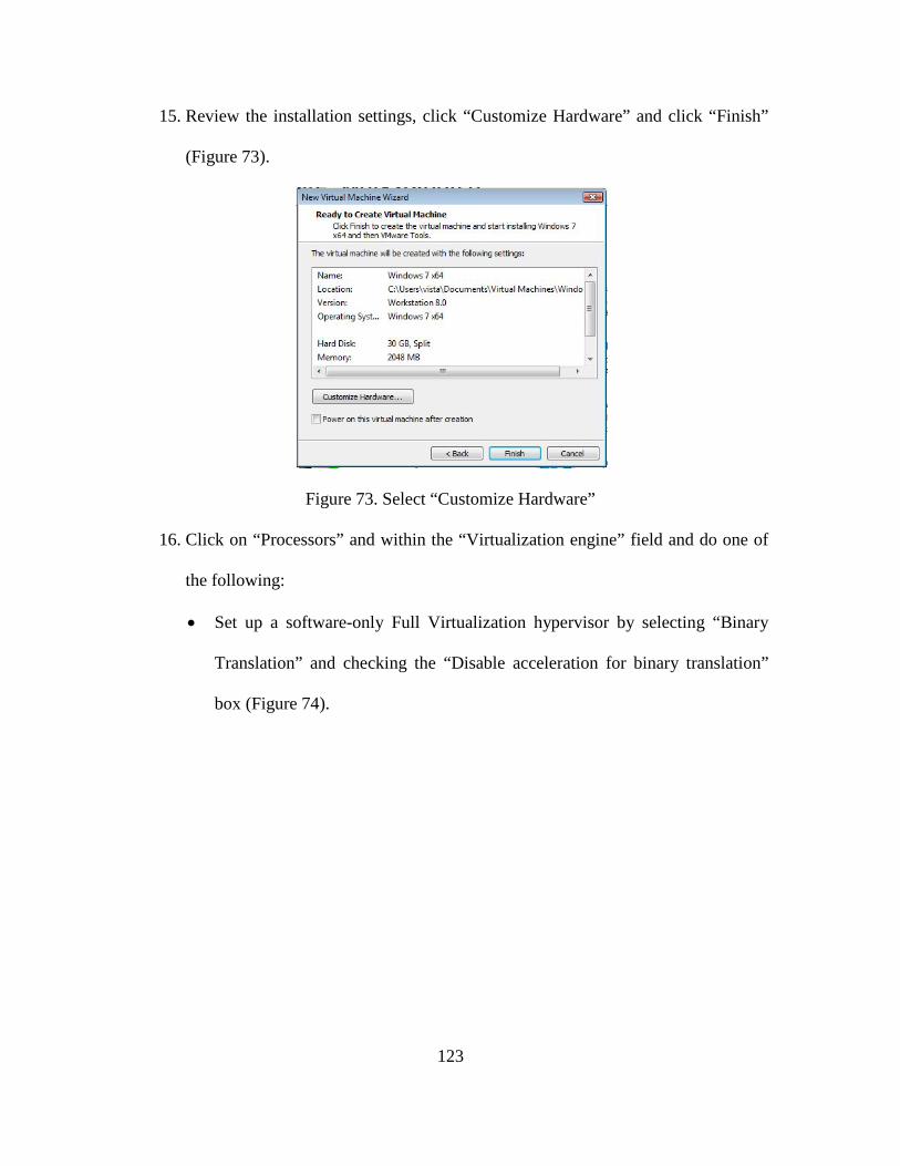
123
15. Review the installation settings, click “Customize Hardware” and click “Finish”
(Figure 73).
Figure 73. Select “Customize Hardware”
16. Click on “Processors” and within the “Virtualization engine” field and do one of
the following:
• Set up a software-only Full Virtualization hypervisor by selecting “Binary
Translation” and checking the “Disable acceleration for binary translation”
box (Figure 74).
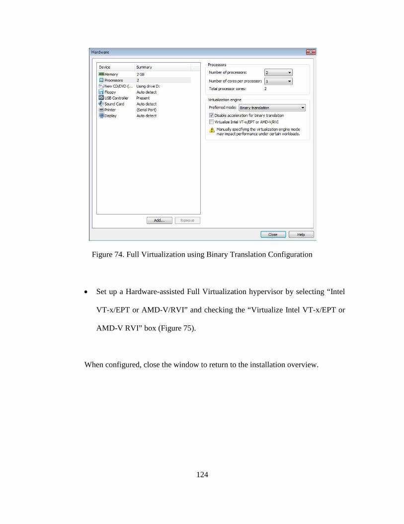
124
Figure 74. Full Virtualization using Binary Translation Configuration
• Set up a Hardware-assisted Full Virtualization hypervisor by selecting “Intel
VT-x/EPT or AMD-V/RVI” and checking the “Virtualize Intel VT-x/EPT or
AMD-V RVI” box (Figure 75).
When configured, close the window to return to the installation overview.
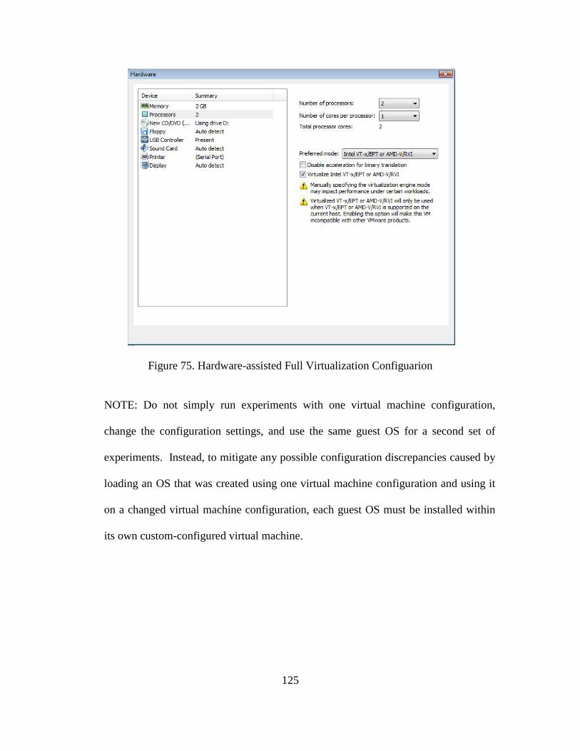
125
Figure 75. Hardware-assisted Full Virtualization Configuarion
NOTE: Do not simply run experiments with one virtual machine configuration,
change the configuration settings, and use the same guest OS for a second set of
experiments. Instead, to mitigate any possible configuration discrepancies caused by
loading an OS that was created using one virtual machine configuration and using it
on a changed virtual machine configuration, each guest OS must be installed within
its own custom-configured virtual machine.
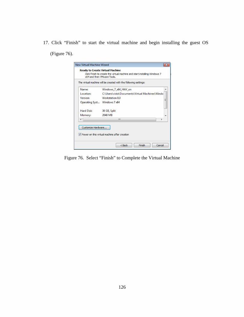
126
17. Click “Finish” to start the virtual machine and begin installing the guest OS
(Figure 76).
Figure 76. Select “Finish” to Complete the Virtual Machine
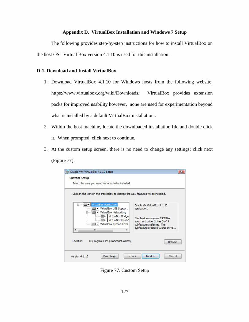
127
Appendix D. VirtualBox Installation and Windows 7 Setup
The following provides step-by-step instructions for how to install VirtualBox on
the host OS. Virtual Box version 4.1.10 is used for this installation.
D-1. Download and Install VirtualBox
1. Download VirtualBox 4.1.10 for Windows hosts from the following website:
https://www.virtualbox.org/wiki/Downloads. VirtualBox provides extension
packs for improved usability however, none are used for experimentation beyond
what is installed by a default VirtualBox installation..
2. Within the host machine, locate the downloaded installation file and double click
it. When prompted, click next to continue.
3. At the custom setup screen, there is no need to change any settings; click next
(Figure 77).
Figure 77. Custom Setup
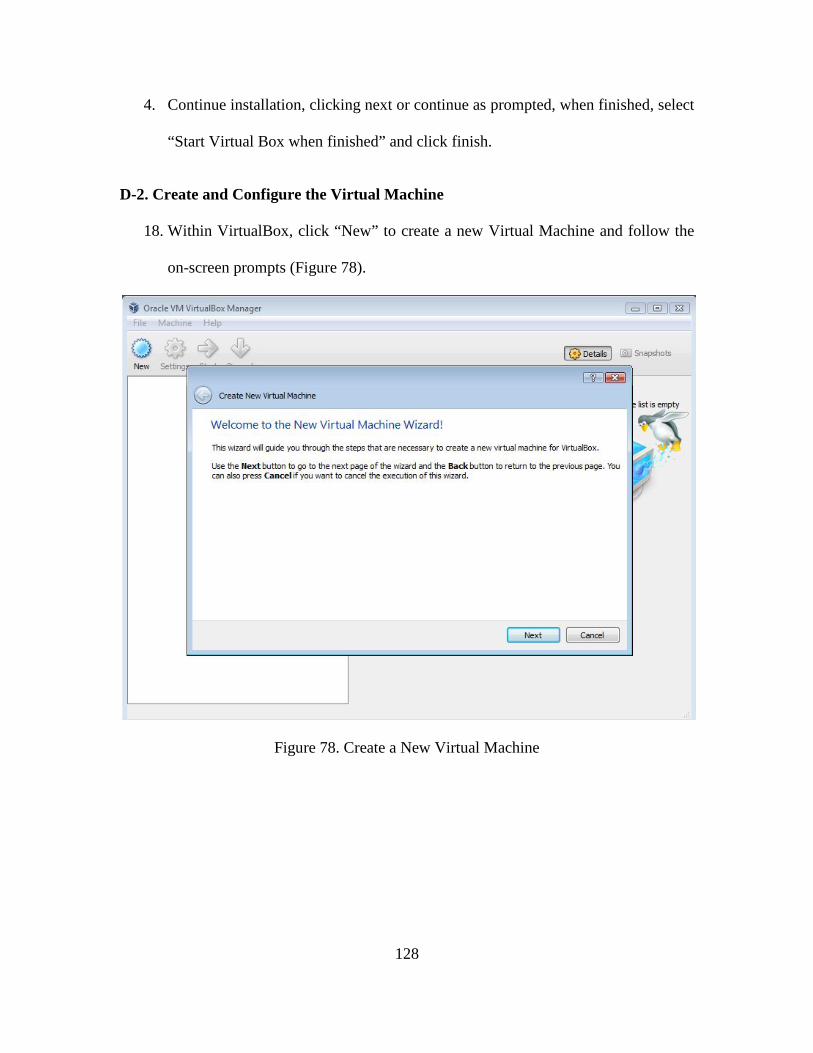
128
4. Continue installation, clicking next or continue as prompted, when finished, select
“Start Virtual Box when finished” and click finish.
D-2. Create and Configure the Virtual Machine
18. Within VirtualBox, click “New” to create a new Virtual Machine and follow the
on-screen prompts (Figure 78).
Figure 78. Create a New Virtual Machine
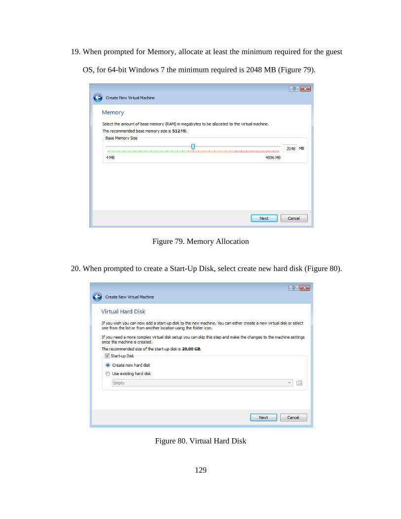
129
19. When prompted for Memory, allocate at least the minimum required for the guest
OS, for 64-bit Windows 7 the minimum required is 2048 MB (Figure 79).
Figure 79. Memory Allocation
20. When prompted to create a Start-Up Disk, select create new hard disk (Figure 80).
Figure 80. Virtual Hard Disk
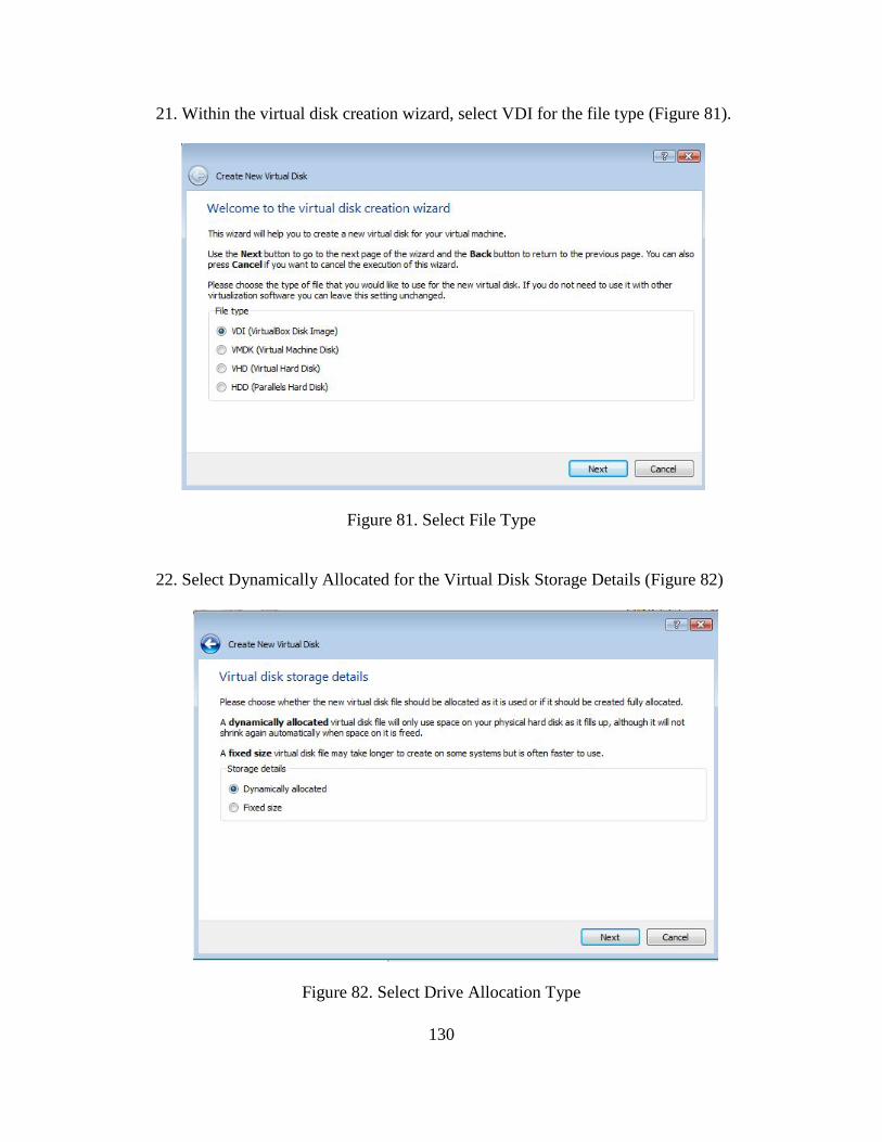
130
21. Within the virtual disk creation wizard, select VDI for the file type (Figure 81).
Figure 81. Select File Type
22. Select Dynamically Allocated for the Virtual Disk Storage Details (Figure 82)
Figure 82. Select Drive Allocation Type
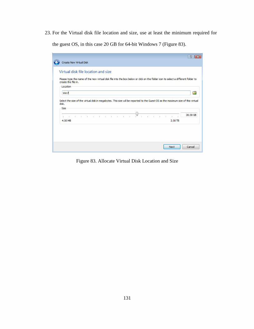
131
23. For the Virtual disk file location and size, use at least the minimum required for
the guest OS, in this case 20 GB for 64-bit Windows 7 (Figure 83).
Figure 83. Allocate Virtual Disk Location and Size
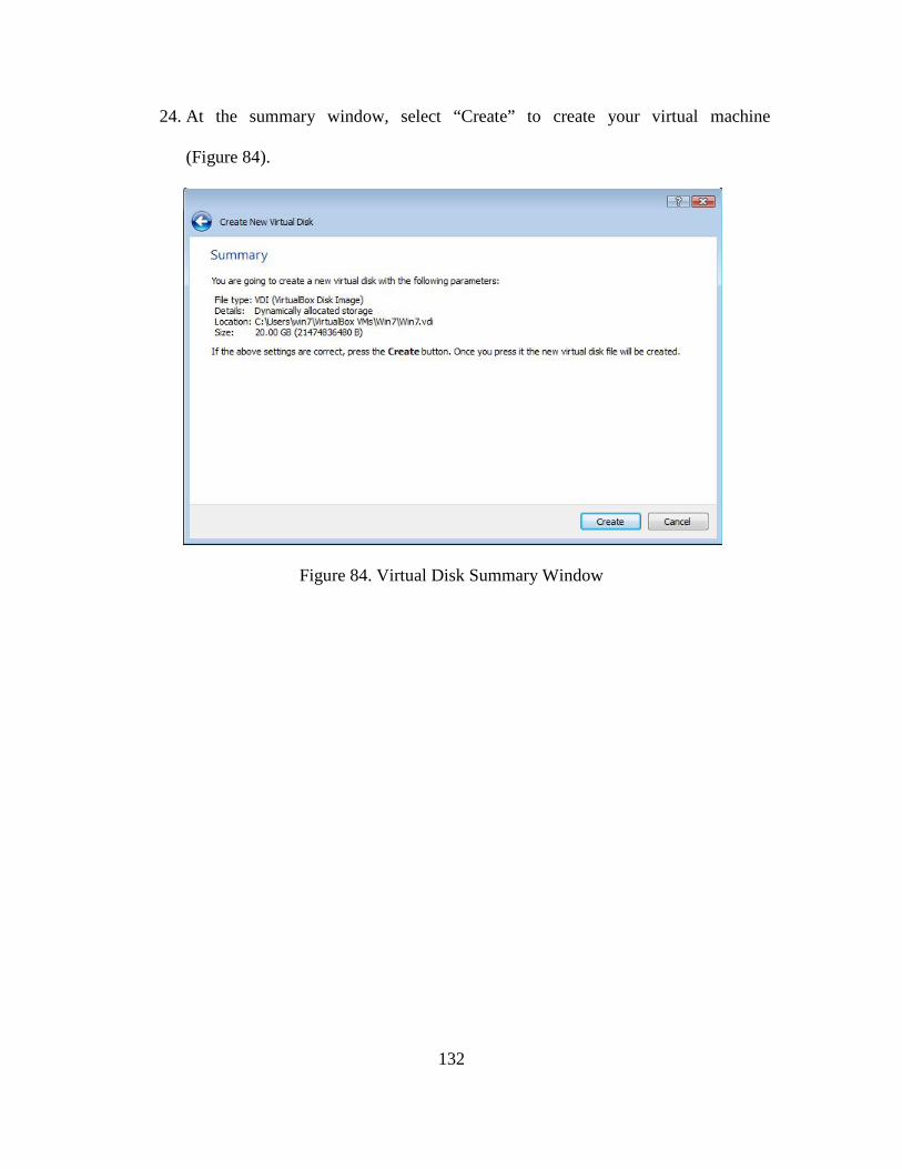
132
24. At the summary window, select “Create” to create your virtual machine
(Figure 84).
Figure 84. Virtual Disk Summary Window
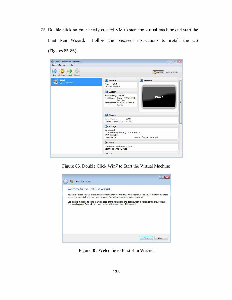
133
25. Double click on your newly created VM to start the virtual machine and start the
First Run Wizard. Follow the onscreen instructions to install the OS
(Figures 85-86).
Figure 85. Double Click Win7 to Start the Virtual Machine
Figure 86. Welcome to First Run Wizard
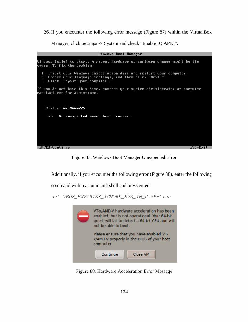
134
26. If you encounter the following error message (Figure 87) within the VirtualBox
Manager, click Settings -> System and check “Enable IO APIC”.
Figure 87. Windows Boot Manager Unexpected Error
Additionally, if you encounter the following error (Figure 88), enter the following
command within a command shell and press enter:
set VBOX_HWVIRTEX_IGNORE_SVM_IN_U SE=true
Figure 88. Hardware Acceleration Error Message
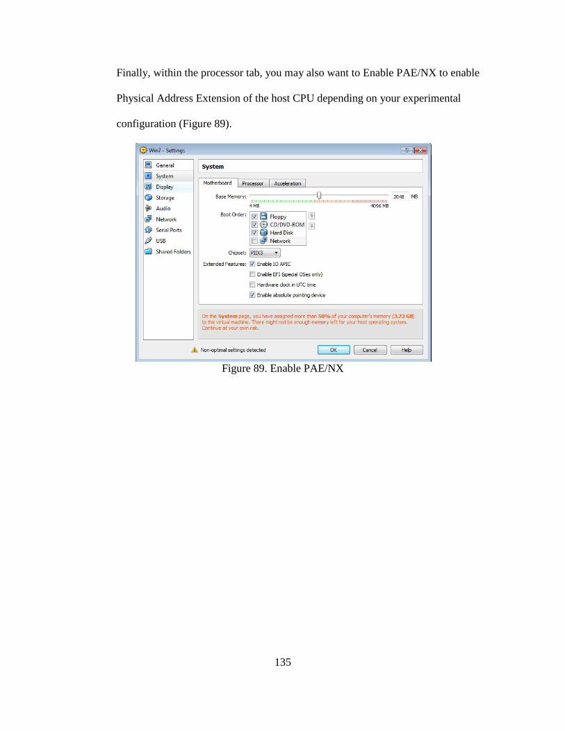
135
Finally, within the processor tab, you may also want to Enable PAE/NX to enable
Physical Address Extension of the host CPU depending on your experimental
configuration (Figure 89).
Figure 89. Enable PAE/NX
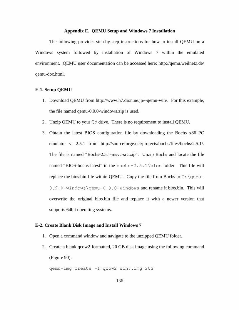
136
Appendix E. QEMU Setup and Windows 7 Installation
The following provides step-by-step instructions for how to install QEMU on a
Windows system followed by installation of Windows 7 within the emulated
environment. QEMU user documentation can be accessed here: http://qemu.weilnetz.de/
qemu-doc.html.
E-1. Setup QEMU
1. Download QEMU from http://www.h7.dion.ne.jp/~qemu-win/. For this example,
the file named qemu-0.9.0-windows.zip is used.
2. Unzip QEMU to your C:\ drive. There is no requirement to install QEMU.
3. Obtain the latest BIOS configuration file by downloading the Bochs x86 PC
emulator v. 2.5.1 from http://sourceforge.net/projects/bochs/files/bochs/2.5.1/.
The file is named “Bochs-2.5.1-msvc-src.zip”. Unzip Bochs and locate the file
named “BIOS-bochs-latest” in the bochs-2.5.1\bios folder. This file will
replace the bios.bin file within QEMU. Copy the file from Bochs to C:\qemu-
0.9.0-windows\qemu-0.9.0-windows and rename it bios.bin. This will
overwrite the original bios.bin file and replace it with a newer version that
supports 64bit operating systems.
E-2. Create Blank Disk Image and Install Windows 7
1. Open a command window and navigate to the unzipped QEMU folder.
2. Create a blank qcow2-formatted, 20 GB disk image using the following command
(Figure 90):
qemu-img create –f qcow2 win7.img 20G
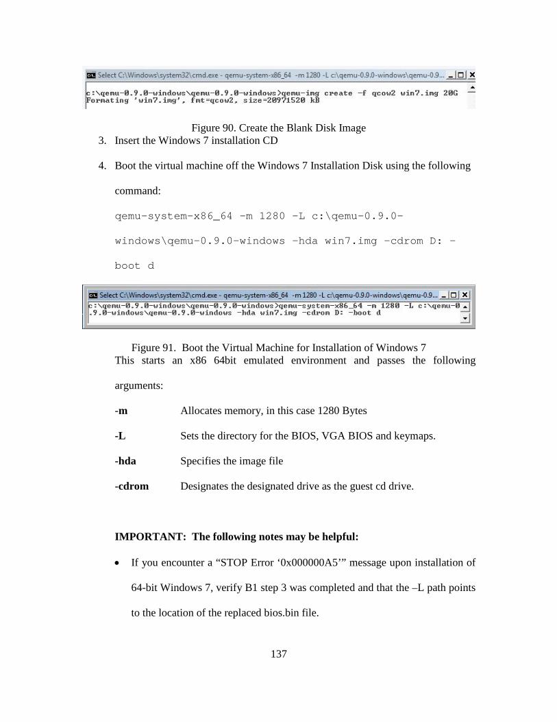
137
Figure 90. Create the Blank Disk Image 3. Insert the Windows 7 installation CD
4. Boot the virtual machine off the Windows 7 Installation Disk using the following
command:
qemu-system-x86_64 –m 1280 –L c:\qemu-0.9.0-
windows\qemu-0.9.0-windows –hda win7.img –cdrom D: -
boot d
Figure 91. Boot the Virtual Machine for Installation of Windows 7 This starts an x86 64bit emulated environment and passes the following
arguments:
-m Allocates memory, in this case 1280 Bytes
-L Sets the directory for the BIOS, VGA BIOS and keymaps.
-hda Specifies the image file
-cdrom Designates the designated drive as the guest cd drive.
IMPORTANT: The following notes may be helpful:
• If you encounter a “STOP Error ‘0x000000A5’” message upon installation of
64-bit Windows 7, verify B1 step 3 was completed and that the –L path points
to the location of the replaced bios.bin file.
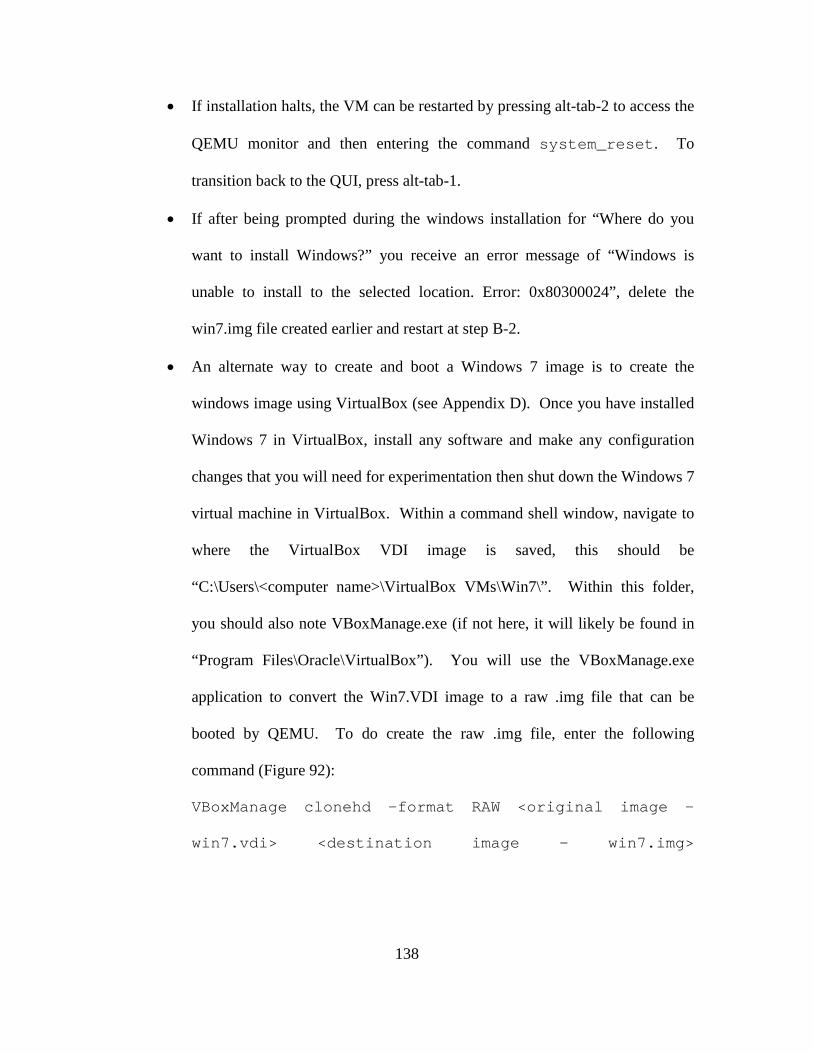
138
• If installation halts, the VM can be restarted by pressing alt-tab-2 to access the
QEMU monitor and then entering the command system_reset. To
transition back to the QUI, press alt-tab-1.
• If after being prompted during the windows installation for “Where do you
want to install Windows?” you receive an error message of “Windows is
unable to install to the selected location. Error: 0x80300024”, delete the
win7.img file created earlier and restart at step B-2.
• An alternate way to create and boot a Windows 7 image is to create the
windows image using VirtualBox (see Appendix D). Once you have installed
Windows 7 in VirtualBox, install any software and make any configuration
changes that you will need for experimentation then shut down the Windows 7
virtual machine in VirtualBox. Within a command shell window, navigate to
where the VirtualBox VDI image is saved, this should be
“C:\Users\<computer name>\VirtualBox VMs\Win7\”. Within this folder,
you should also note VBoxManage.exe (if not here, it will likely be found in
“Program Files\Oracle\VirtualBox”). You will use the VBoxManage.exe
application to convert the Win7.VDI image to a raw .img file that can be
booted by QEMU. To do create the raw .img file, enter the following
command (Figure 92):
VBoxManage clonehd –format RAW <original image -
win7.vdi> <destination image - win7.img>
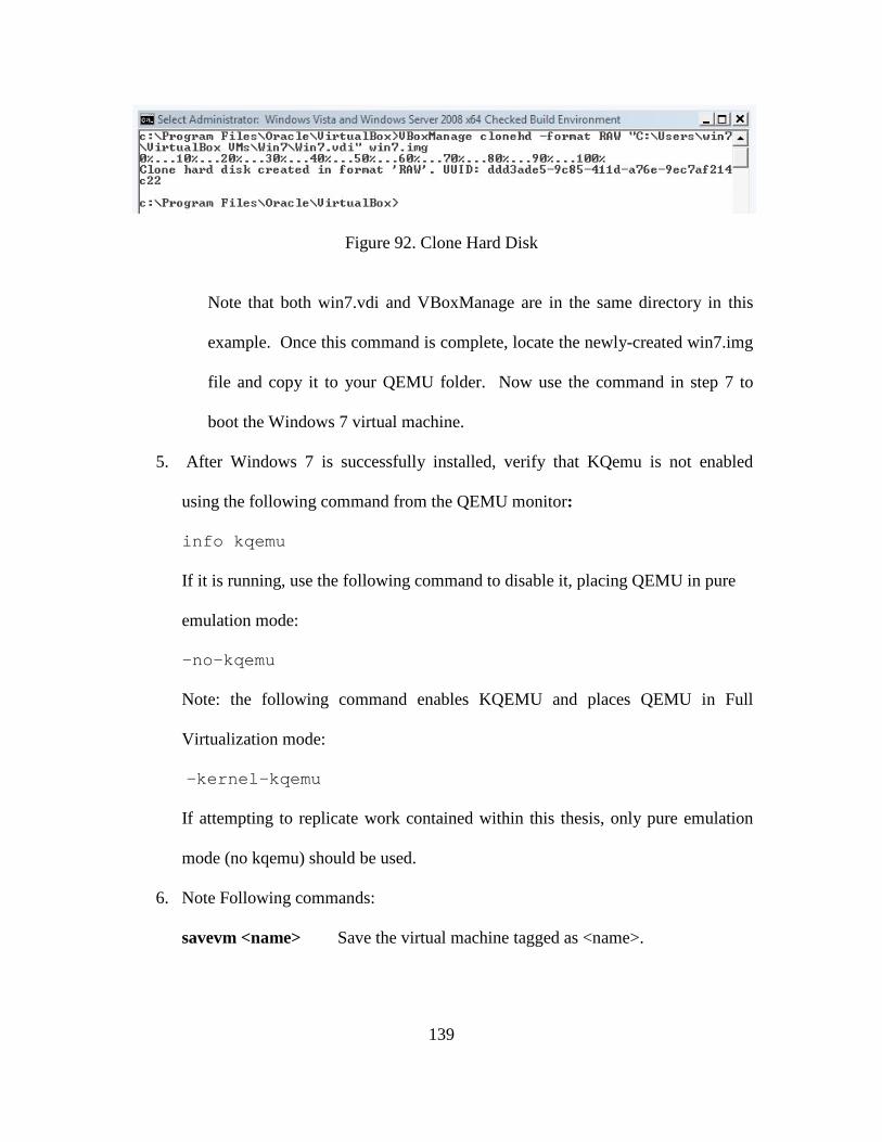
139
Figure 92. Clone Hard Disk
Note that both win7.vdi and VBoxManage are in the same directory in this
example. Once this command is complete, locate the newly-created win7.img
file and copy it to your QEMU folder. Now use the command in step 7 to
boot the Windows 7 virtual machine.
5. After Windows 7 is successfully installed, verify that KQemu is not enabled
using the following command from the QEMU monitor:
info kqemu
If it is running, use the following command to disable it, placing QEMU in pure
emulation mode:
-no-kqemu
Note: the following command enables KQEMU and places QEMU in Full
Virtualization mode:
-kernel-kqemu
If attempting to replicate work contained within this thesis, only pure emulation
mode (no kqemu) should be used.
6. Note Following commands:
savevm <name> Save the virtual machine tagged as <name>.
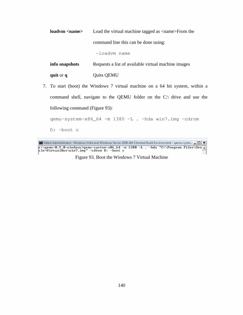
140
loadvm <name> Load the virtual machine tagged as <name>From the
command line this can be done using:
-loadvm name
info snapshots Requests a list of available virtual machine images
quit or q Quits QEMU
7. To start (boot) the Windows 7 virtual machine on a 64 bit system, within a
command shell, navigate to the QEMU folder on the C:\ drive and use the
following command (Figure 93):
qemu-system-x86_64 –m 1380 –L . –hda win7.img –cdrom
D: -boot c
Figure 93. Boot the Windows 7 Virtual Machine
141
Appendix F. BluePill Installation on Windows Vista 64
The following provides step-by-step instructions for how to install BluePill v.0.32
as released by Invisible Things Lab. For installation, you must be running Windows
Vista 64 on a processor that supports either Intel VT-x or AMD-V. Additionally, you
must enable virtualization within the BIOS.
To install BluePill, the driver signing constraints of Windows Vista must be
addressed. Windows Vista 64 requires that all drivers are digitally signed before they are
allowed to execute. Within a real-world HAV-R attack scenario, this is one of the
challenges which must be overcome for installation within a targeted system. Within an
academic or development environment, it is possible to circumvent this requirement
through use of test signing. Test-signing uses a test certificate to allow developers to
fully test their code to ensure intended operation before obtaining a real certificate
[MSN12].
F-1. Enable Test-Signing, Disable Integrity Checks, and Install WinDK
1. Enable Test-Signing, Disable Integrity Checks, and install WinDK as detailed in
Appendix B.
F-2. Build the BluePill Driver
1. Copy nbp-0.32-public.zip to your computer and unzip the files. It may be easiest
to copy the unzipped files directly onto the c:\ drive. Note that this release
provides three components:
• nbp-0.32-public which contains newbp.sys, the BluePill driver.
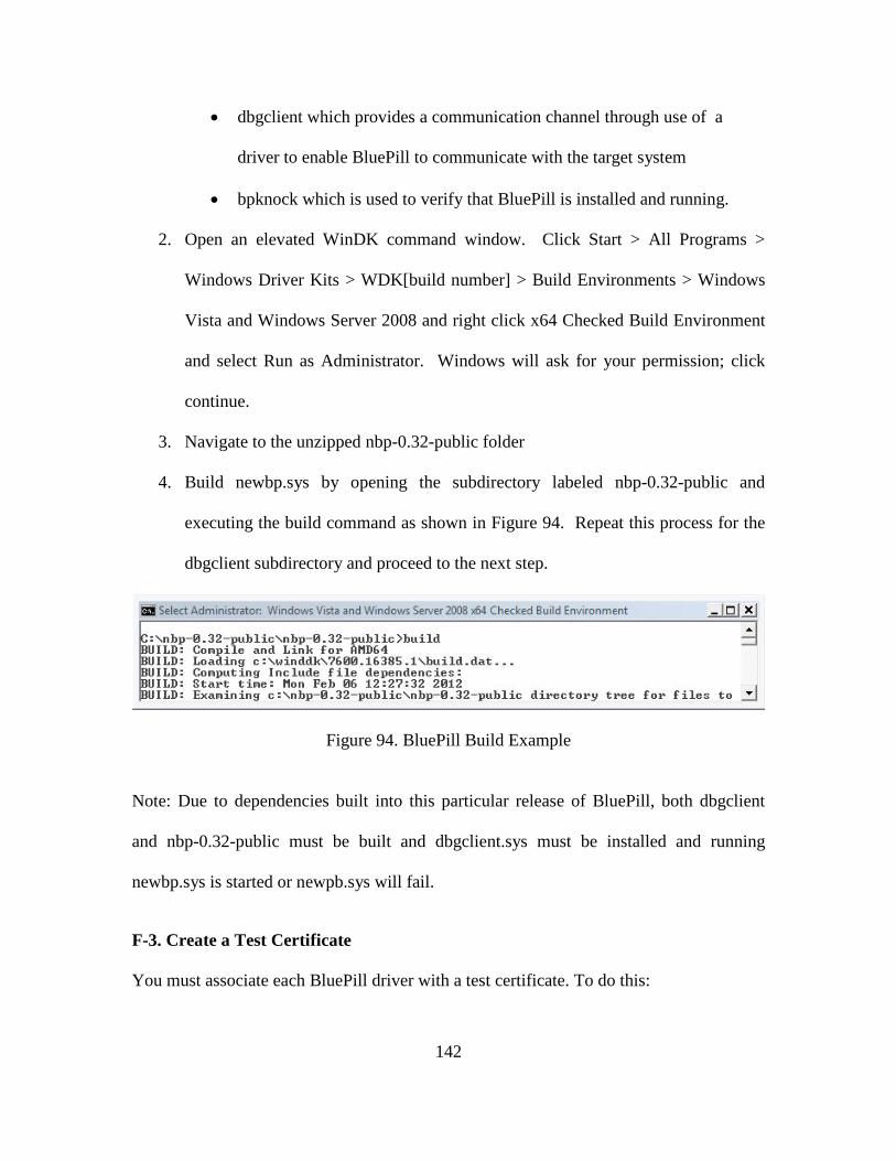
142
• dbgclient which provides a communication channel through use of a
driver to enable BluePill to communicate with the target system
• bpknock which is used to verify that BluePill is installed and running.
2. Open an elevated WinDK command window. Click Start > All Programs >
Windows Driver Kits > WDK[build number] > Build Environments > Windows
Vista and Windows Server 2008 and right click x64 Checked Build Environment
and select Run as Administrator. Windows will ask for your permission; click
continue.
3. Navigate to the unzipped nbp-0.32-public folder
4. Build newbp.sys by opening the subdirectory labeled nbp-0.32-public and
executing the build command as shown in Figure 94. Repeat this process for the
dbgclient subdirectory and proceed to the next step.
Figure 94. BluePill Build Example
Note: Due to dependencies built into this particular release of BluePill, both dbgclient
and nbp-0.32-public must be built and dbgclient.sys must be installed and running
newbp.sys is started or newpb.sys will fail.
F-3. Create a Test Certificate
You must associate each BluePill driver with a test certificate. To do this:
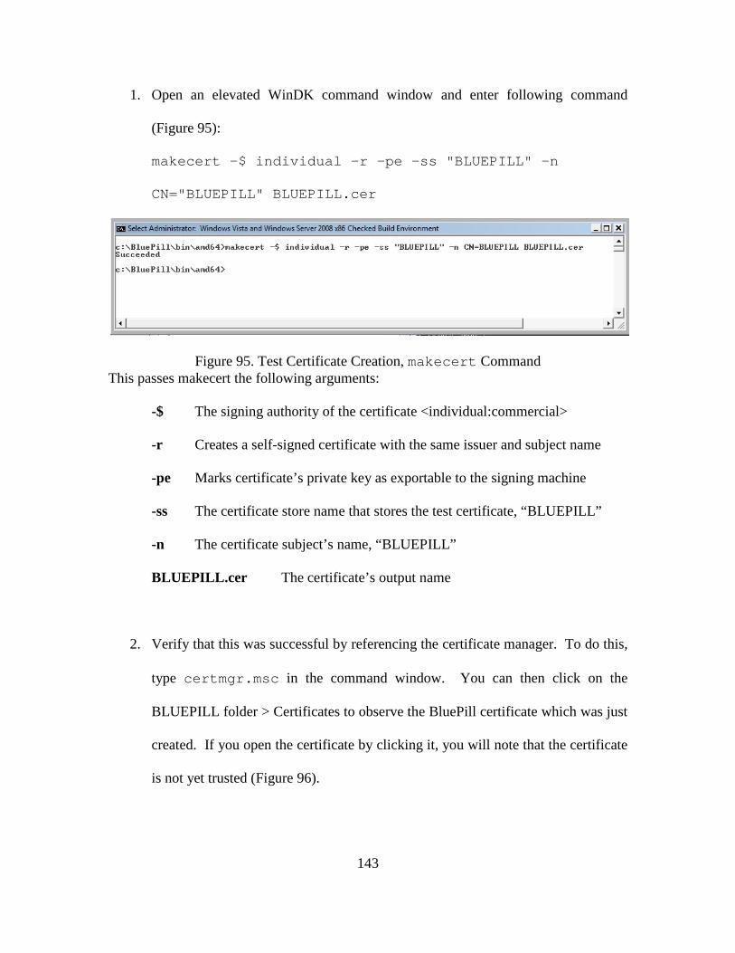
143
1. Open an elevated WinDK command window and enter following command
(Figure 95):
makecert -$ individual -r -pe -ss "BLUEPILL" -n
CN="BLUEPILL" BLUEPILL.cer
Figure 95. Test Certificate Creation, makecert Command This passes makecert the following arguments:
-$ The signing authority of the certificate <individual:commercial>
-r Creates a self-signed certificate with the same issuer and subject name
-pe Marks certificate’s private key as exportable to the signing machine
-ss The certificate store name that stores the test certificate, “BLUEPILL”
-n The certificate subject’s name, “BLUEPILL”
BLUEPILL.cer The certificate’s output name
2. Verify that this was successful by referencing the certificate manager. To do this,
type certmgr.msc in the command window. You can then click on the
BLUEPILL folder > Certificates to observe the BluePill certificate which was just
created. If you open the certificate by clicking it, you will note that the certificate
is not yet trusted (Figure 96).
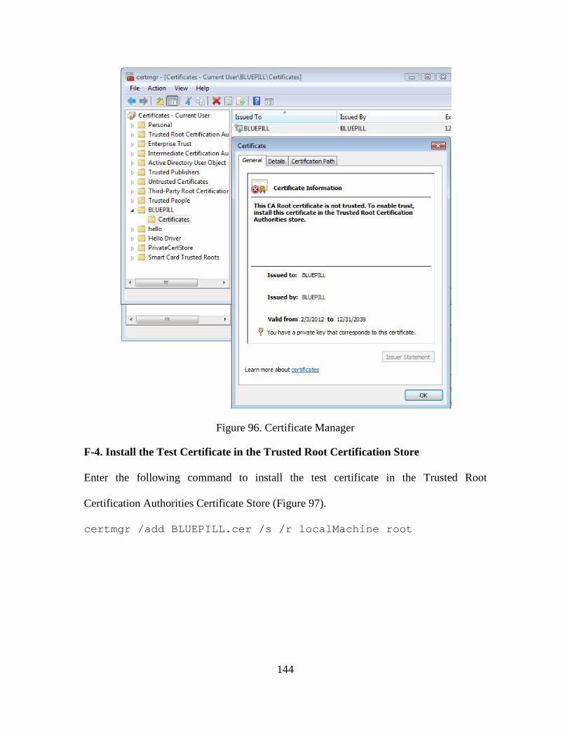
144
Figure 96. Certificate Manager
F-4. Install the Test Certificate in the Trusted Root Certification Store
Enter the following command to install the test certificate in the Trusted Root
Certification Authorities Certificate Store (Figure 97).
certmgr /add BLUEPILL.cer /s /r localMachine root
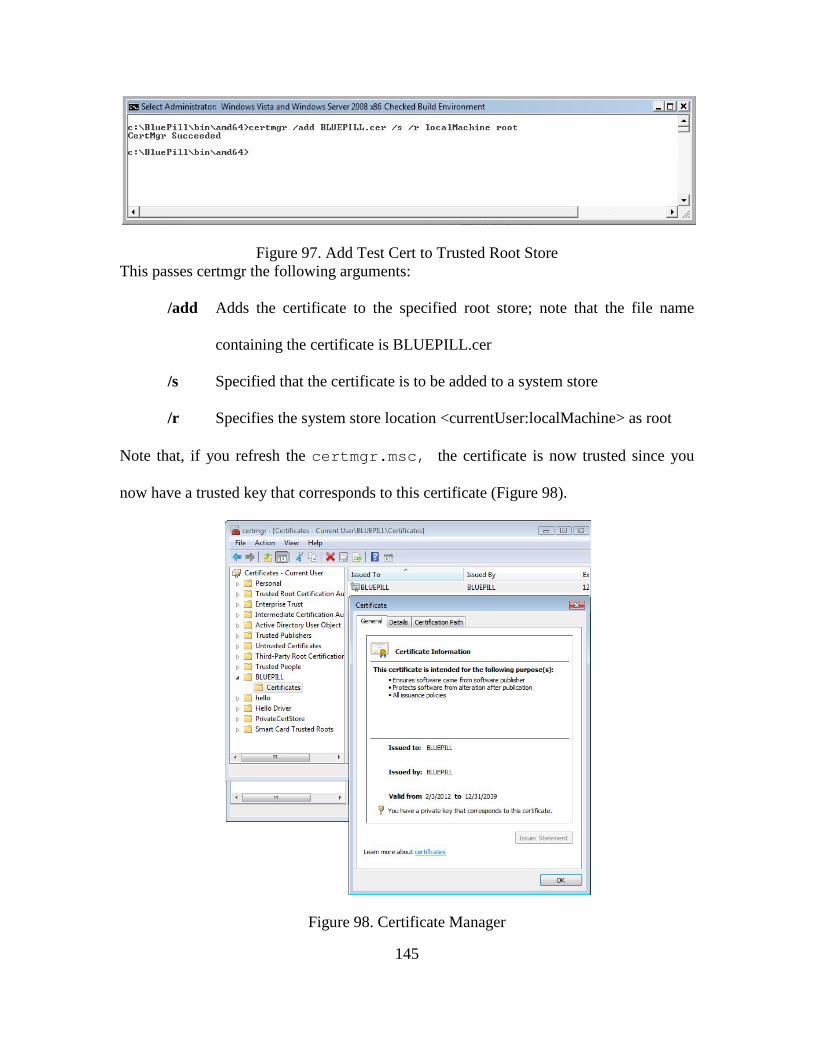
145
Figure 97. Add Test Cert to Trusted Root Store This passes certmgr the following arguments:
/add Adds the certificate to the specified root store; note that the file name
containing the certificate is BLUEPILL.cer
/s Specified that the certificate is to be added to a system store
/r Specifies the system store location <currentUser:localMachine> as root
Note that, if you refresh the certmgr.msc, the certificate is now trusted since you
now have a trusted key that corresponds to this certificate (Figure 98).
Figure 98. Certificate Manager
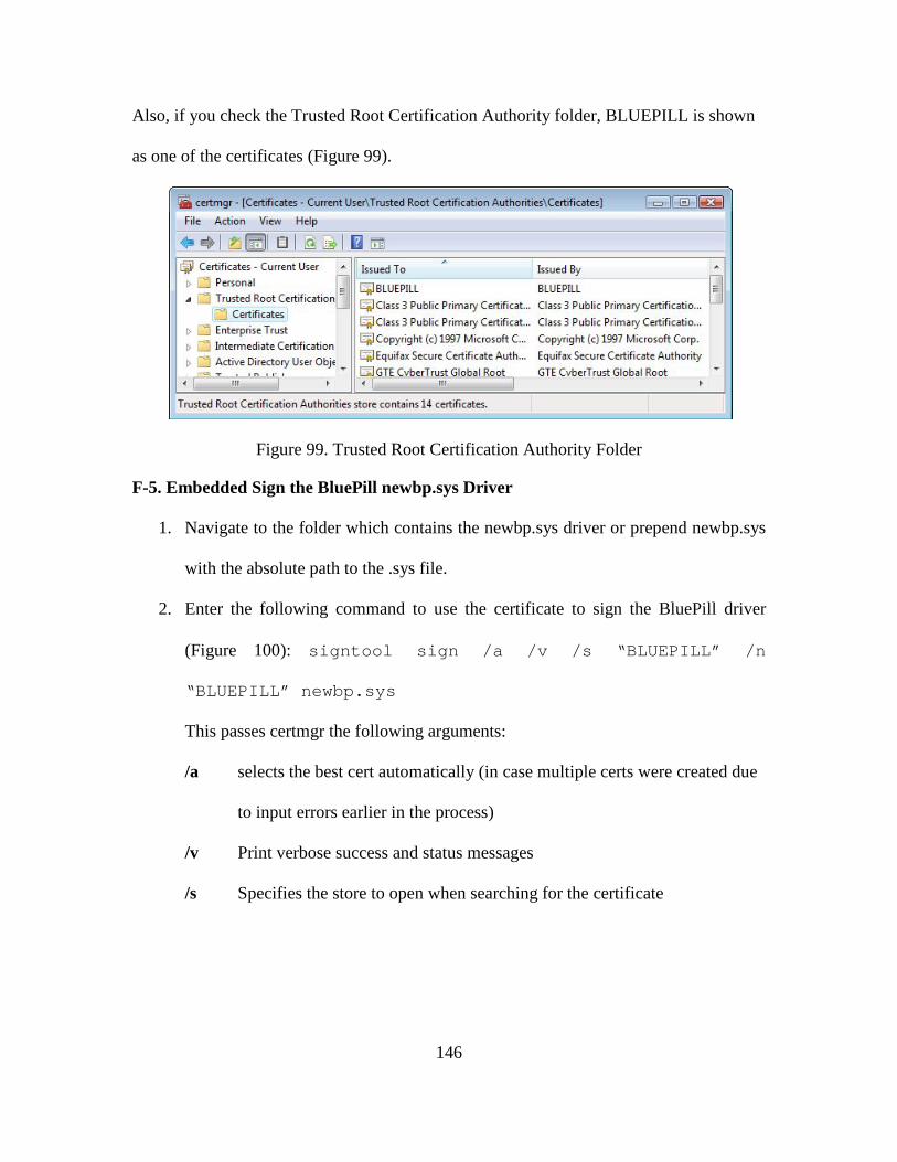
146
Also, if you check the Trusted Root Certification Authority folder, BLUEPILL is shown
as one of the certificates (Figure 99).
Figure 99. Trusted Root Certification Authority Folder
F-5. Embedded Sign the BluePill newbp.sys Driver
1. Navigate to the folder which contains the newbp.sys driver or prepend newbp.sys
with the absolute path to the .sys file.
2. Enter the following command to use the certificate to sign the BluePill driver
(Figure 100): signtool sign /a /v /s “BLUEPILL” /n
“BLUEPILL” newbp.sys
This passes certmgr the following arguments:
/a selects the best cert automatically (in case multiple certs were created due
to input errors earlier in the process)
/v Print verbose success and status messages
/s Specifies the store to open when searching for the certificate
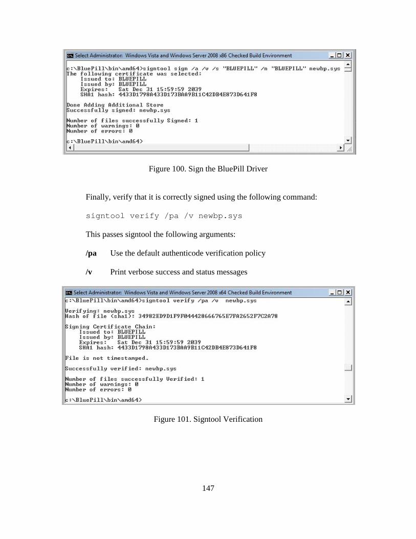
147
Figure 100. Sign the BluePill Driver
Finally, verify that it is correctly signed using the following command:
signtool verify /pa /v newbp.sys
This passes signtool the following arguments:
/pa Use the default authenticode verification policy
/v Print verbose success and status messages
Figure 101. Signtool Verification
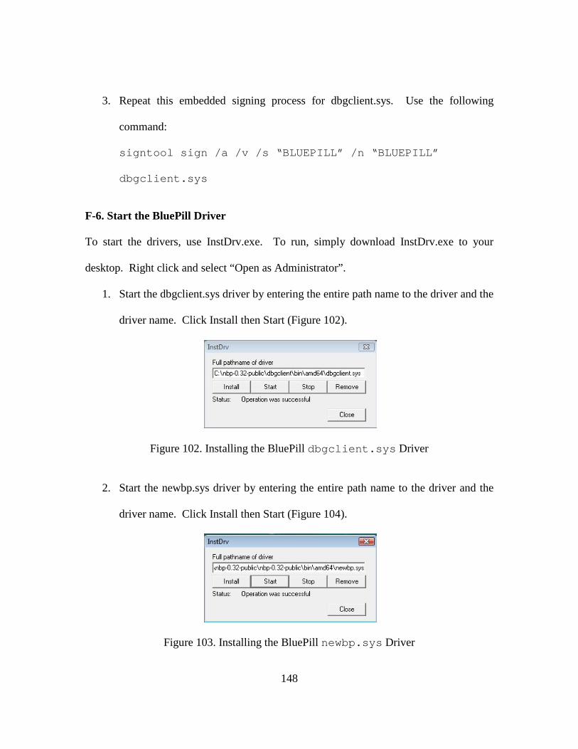
148
3. Repeat this embedded signing process for dbgclient.sys. Use the following
command:
signtool sign /a /v /s “BLUEPILL” /n “BLUEPILL”
dbgclient.sys
F-6. Start the BluePill Driver
To start the drivers, use InstDrv.exe. To run, simply download InstDrv.exe to your
desktop. Right click and select “Open as Administrator”.
1. Start the dbgclient.sys driver by entering the entire path name to the driver and the
driver name. Click Install then Start (Figure 102).
Figure 102. Installing the BluePill dbgclient.sys Driver
2. Start the newbp.sys driver by entering the entire path name to the driver and the
driver name. Click Install then Start (Figure 104).
Figure 103. Installing the BluePill newbp.sys Driver
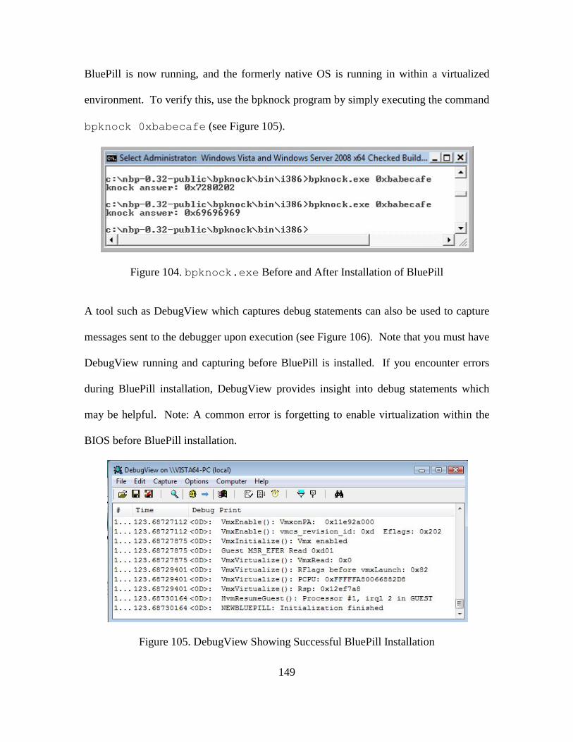
149
BluePill is now running, and the formerly native OS is running in within a virtualized
environment. To verify this, use the bpknock program by simply executing the command
bpknock 0xbabecafe (see Figure 105).
Figure 104. bpknock.exe Before and After Installation of BluePill
A tool such as DebugView which captures debug statements can also be used to capture
messages sent to the debugger upon execution (see Figure 106). Note that you must have
DebugView running and capturing before BluePill is installed. If you encounter errors
during BluePill installation, DebugView provides insight into debug statements which
may be helpful. Note: A common error is forgetting to enable virtualization within the
BIOS before BluePill installation.
Figure 105. DebugView Showing Successful BluePill Installation
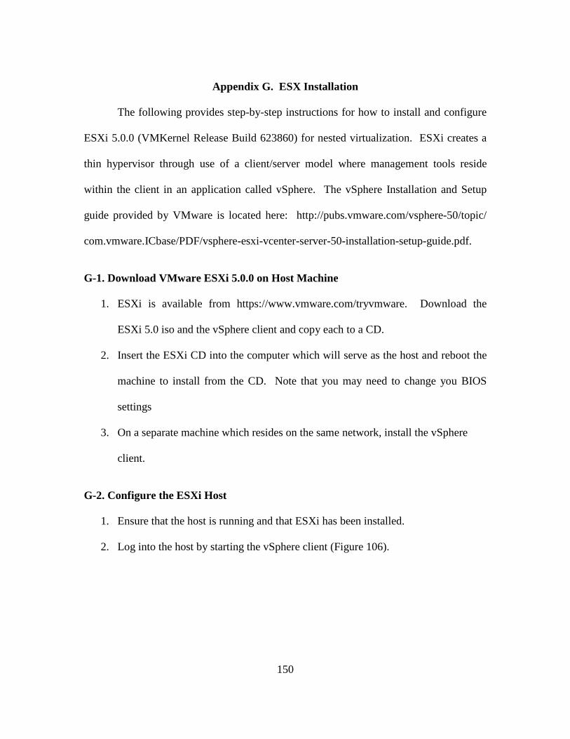
150
Appendix G. ESX Installation
The following provides step-by-step instructions for how to install and configure
ESXi 5.0.0 (VMKernel Release Build 623860) for nested virtualization. ESXi creates a
thin hypervisor through use of a client/server model where management tools reside
within the client in an application called vSphere. The vSphere Installation and Setup
guide provided by VMware is located here: http://pubs.vmware.com/vsphere-50/topic/
com.vmware.ICbase/PDF/vsphere-esxi-vcenter-server-50-installation-setup-guide.pdf.
G-1. Download VMware ESXi 5.0.0 on Host Machine
1. ESXi is available from https://www.vmware.com/tryvmware. Download the
ESXi 5.0 iso and the vSphere client and copy each to a CD.
2. Insert the ESXi CD into the computer which will serve as the host and reboot the
machine to install from the CD. Note that you may need to change you BIOS
settings
3. On a separate machine which resides on the same network, install the vSphere
client.
G-2. Configure the ESXi Host
1. Ensure that the host is running and that ESXi has been installed.
2. Log into the host by starting the vSphere client (Figure 106).
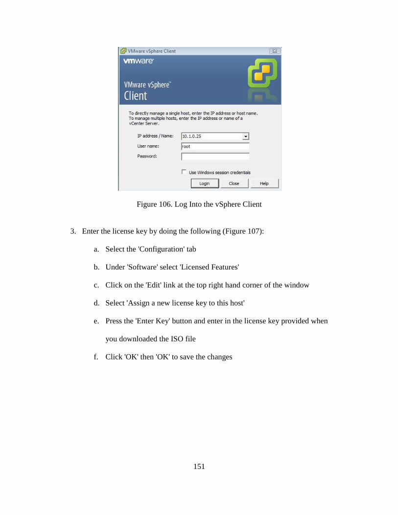
151
Figure 106. Log Into the vSphere Client
3. Enter the license key by doing the following (Figure 107):
a. Select the 'Configuration' tab
b. Under 'Software' select 'Licensed Features'
c. Click on the 'Edit' link at the top right hand corner of the window
d. Select 'Assign a new license key to this host'
e. Press the 'Enter Key' button and enter in the license key provided when
you downloaded the ISO file
f. Click 'OK' then 'OK' to save the changes
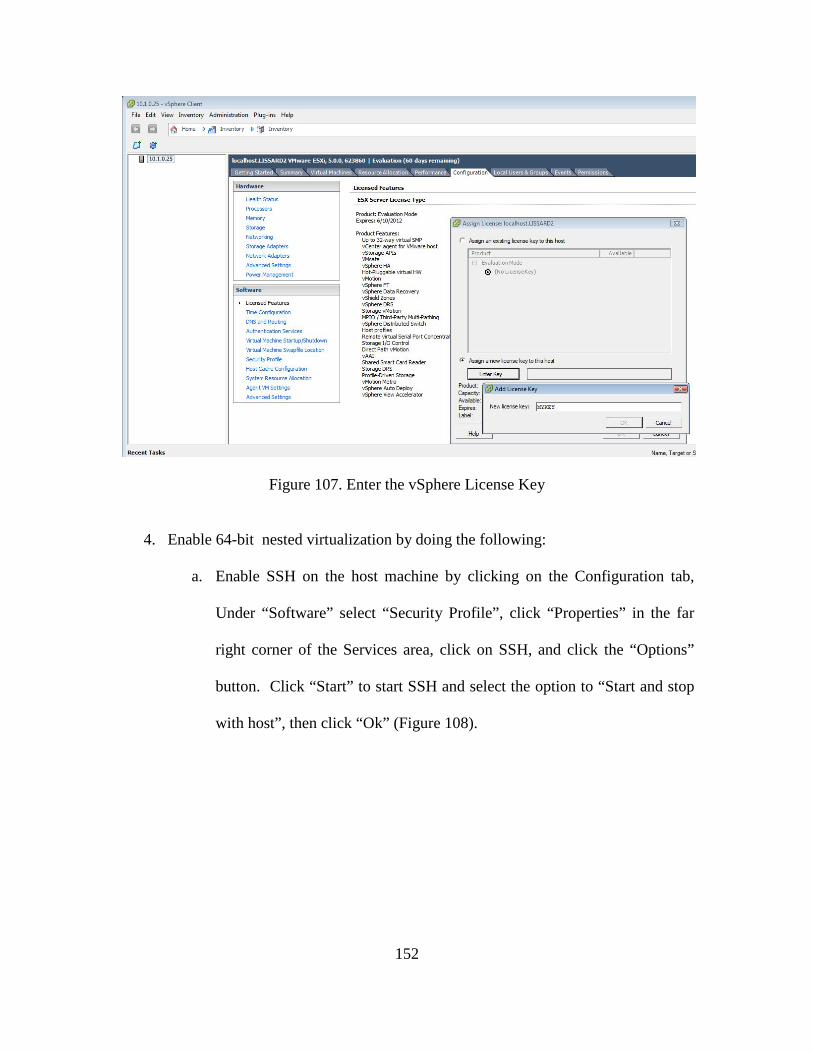
152
Figure 107. Enter the vSphere License Key
4. Enable 64-bit nested virtualization by doing the following:
a. Enable SSH on the host machine by clicking on the Configuration tab,
Under “Software” select “Security Profile”, click “Properties” in the far
right corner of the Services area, click on SSH, and click the “Options”
button. Click “Start” to start SSH and select the option to “Start and stop
with host”, then click “Ok” (Figure 108).
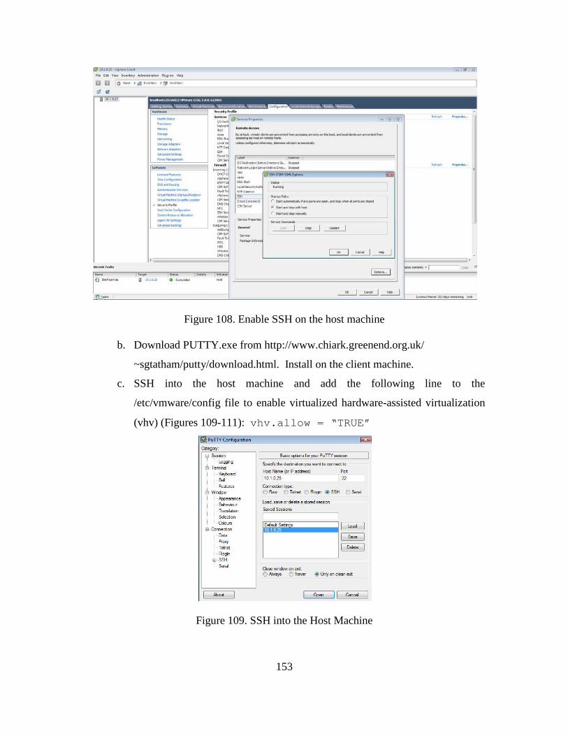
153
Figure 108. Enable SSH on the host machine
b. Download PUTTY.exe from http://www.chiark.greenend.org.uk/
~sgtatham/putty/download.html. Install on the client machine.
c. SSH into the host machine and add the following line to the
/etc/vmware/config file to enable virtualized hardware-assisted virtualization
(vhv) (Figures 109-111): vhv.allow = “TRUE”
Figure 109. SSH into the Host Machine
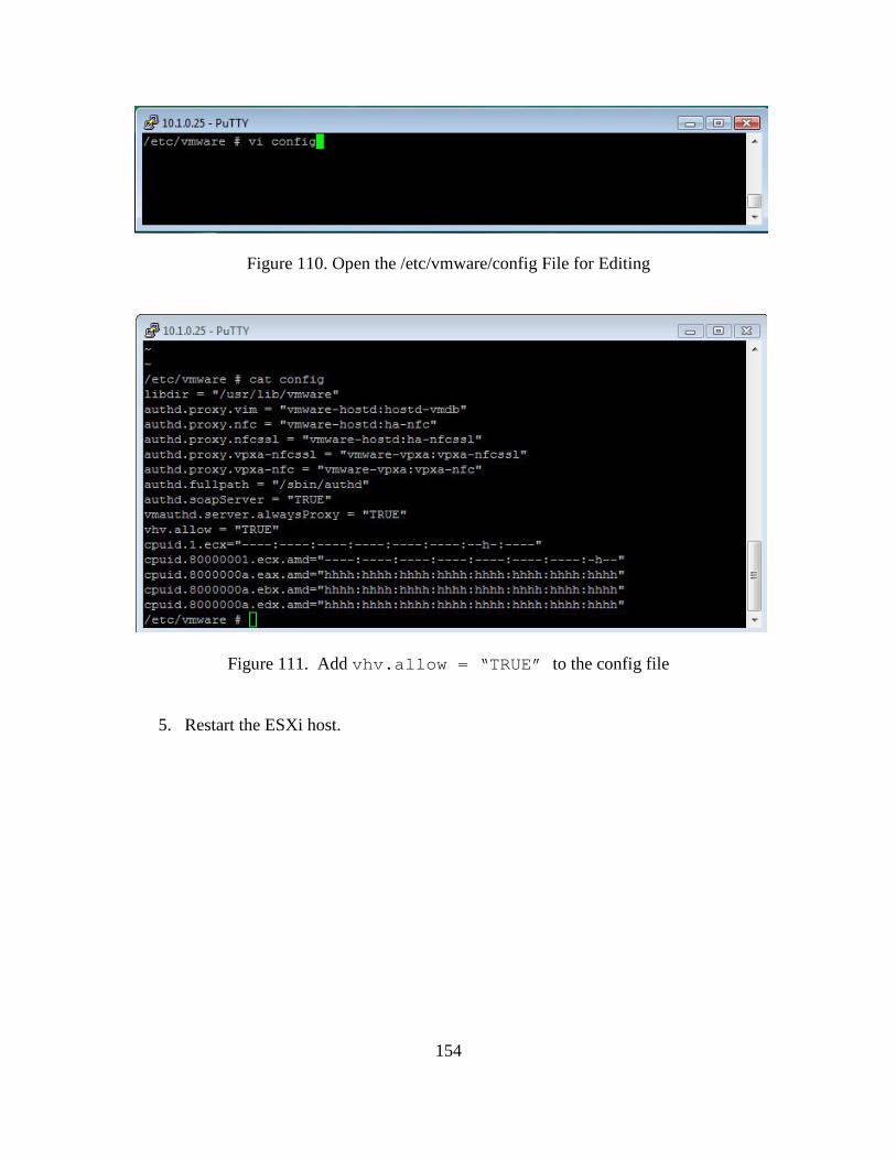
154
Figure 110. Open the /etc/vmware/config File for Editing
Figure 111. Add vhv.allow = “TRUE” to the config file
5. Restart the ESXi host.
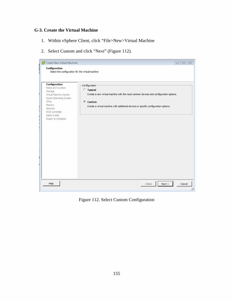
155
G-3. Create the Virtual Machine
1. Within vSphere Client, click “File>New>Virtual Machine
2. Select Custom and click “Next” (Figure 112).
Figure 112. Select Custom Configuration
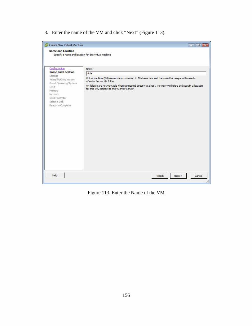
156
3. Enter the name of the VM and click “Next” (Figure 113).
Figure 113. Enter the Name of the VM
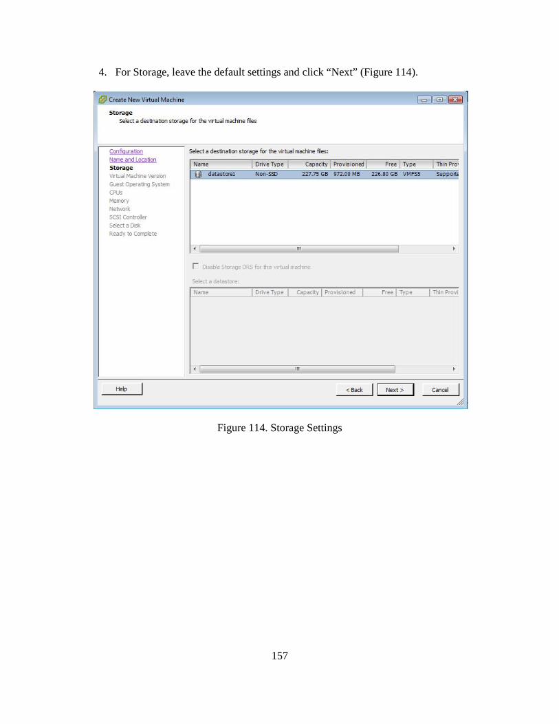
157
4. For Storage, leave the default settings and click “Next” (Figure 114).
Figure 114. Storage Settings
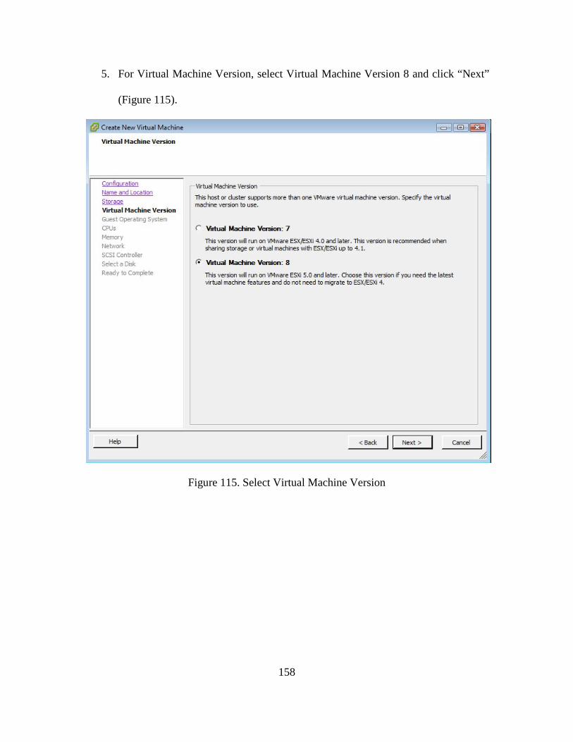
158
5. For Virtual Machine Version, select Virtual Machine Version 8 and click “Next”
(Figure 115).
Figure 115. Select Virtual Machine Version
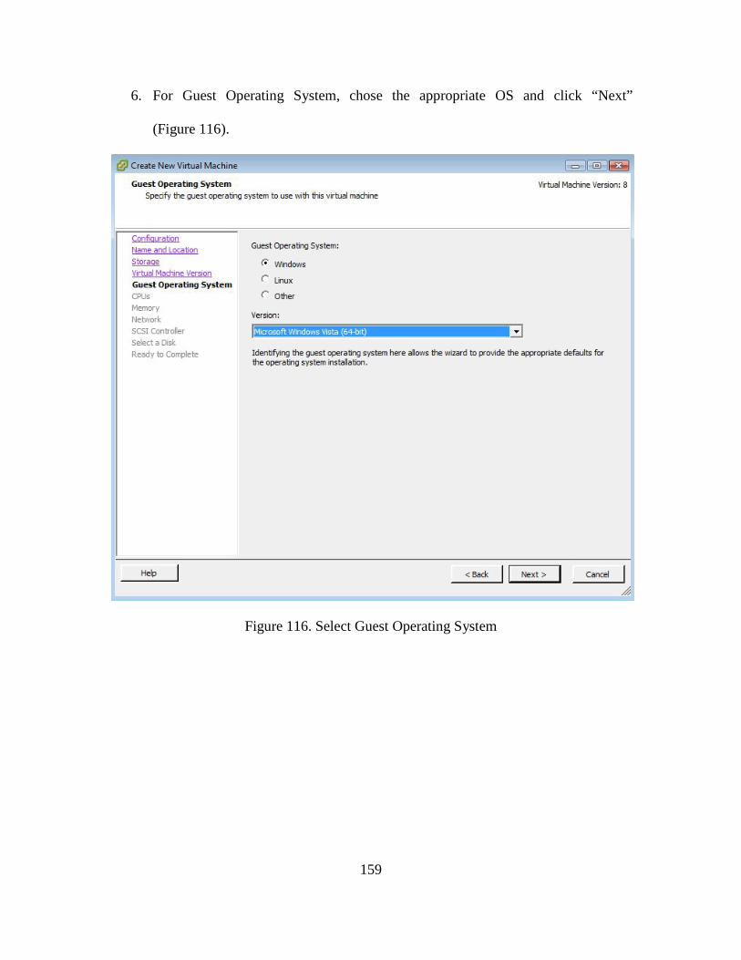
159
6. For Guest Operating System, chose the appropriate OS and click “Next”
(Figure 116).
Figure 116. Select Guest Operating System
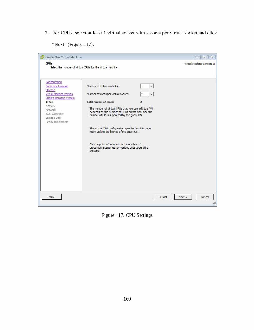
160
7. For CPUs, select at least 1 virtual socket with 2 cores per virtual socket and click
“Next” (Figure 117).
Figure 117. CPU Settings
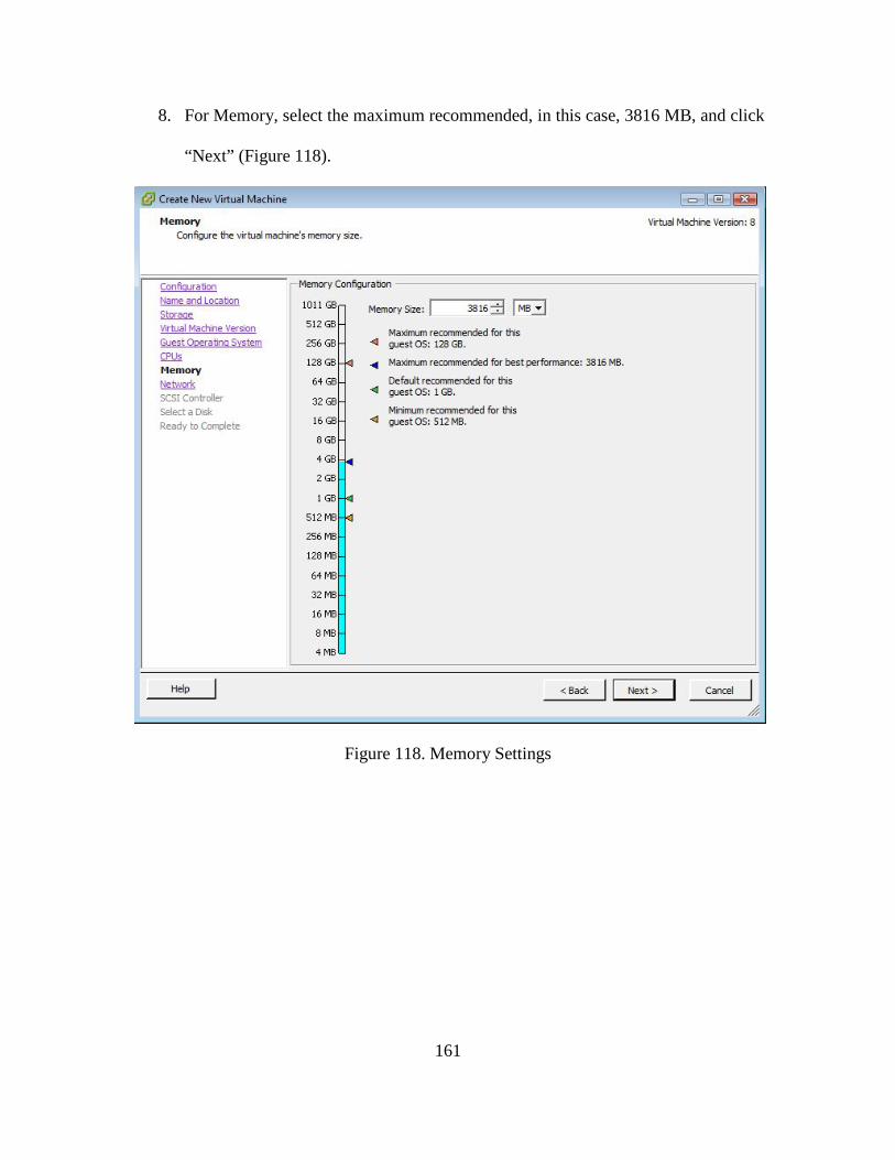
161
8. For Memory, select the maximum recommended, in this case, 3816 MB, and click
“Next” (Figure 118).
Figure 118. Memory Settings
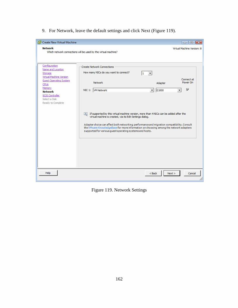
162
9. For Network, leave the default settings and click Next (Figure 119).
Figure 119. Network Settings
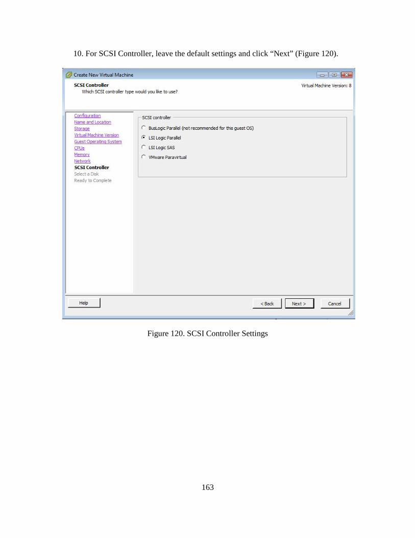
163
10. For SCSI Controller, leave the default settings and click “Next” (Figure 120).
Figure 120. SCSI Controller Settings
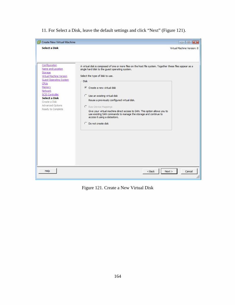
164
11. For Select a Disk, leave the default settings and click “Next” (Figure 121).
Figure 121. Create a New Virtual Disk
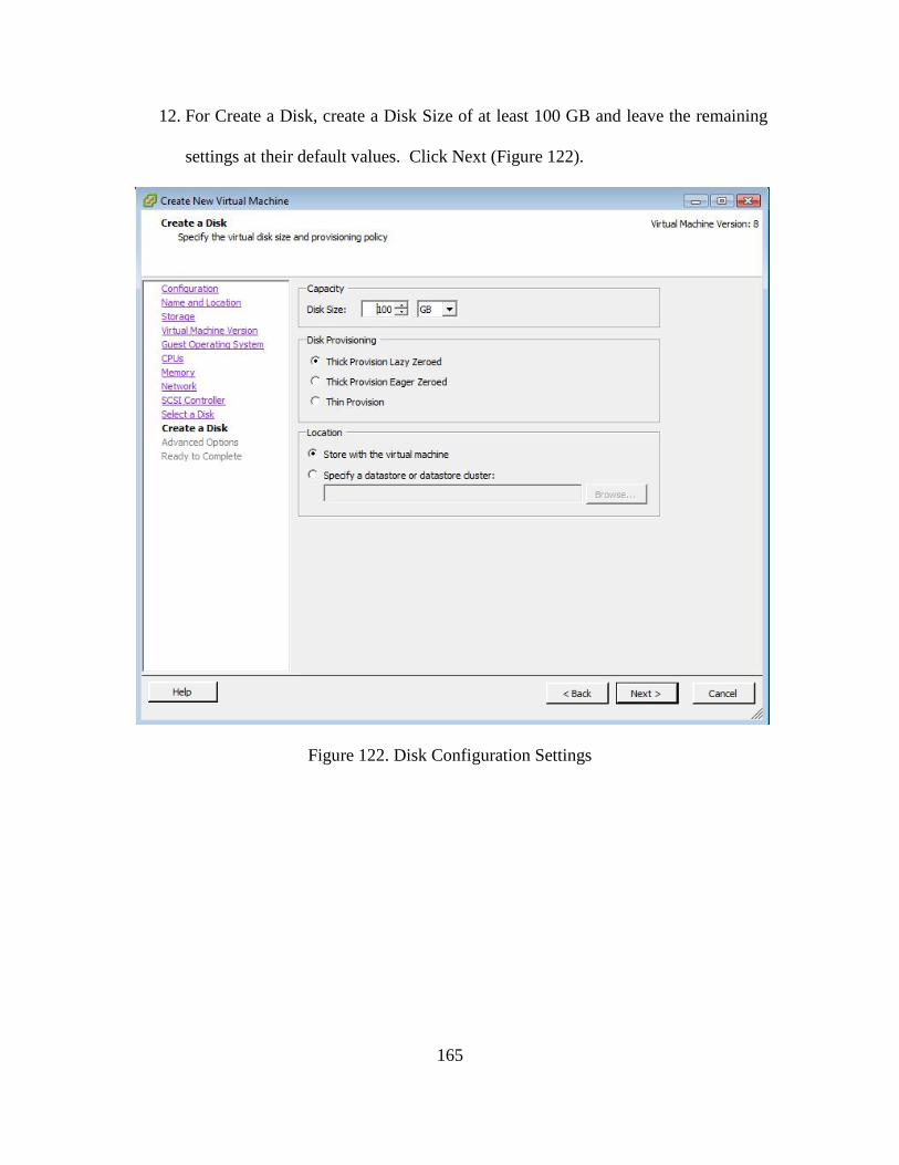
165
12. For Create a Disk, create a Disk Size of at least 100 GB and leave the remaining
settings at their default values. Click Next (Figure 122).
Figure 122. Disk Configuration Settings
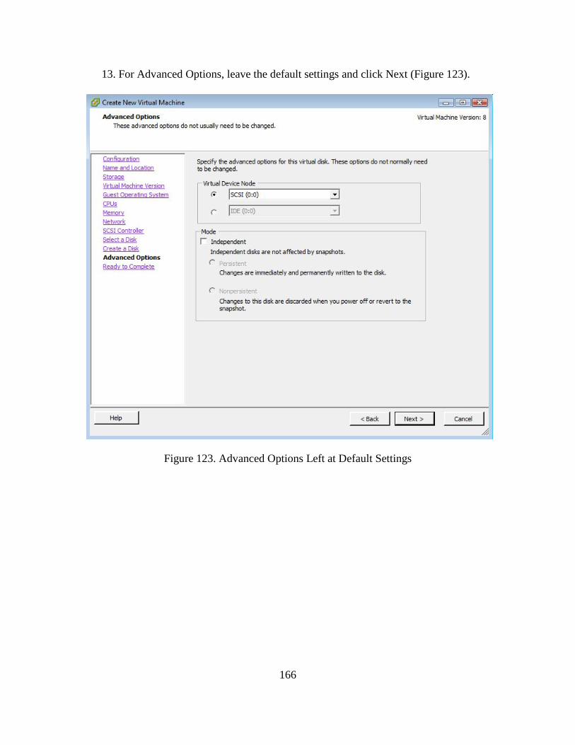
166
13. For Advanced Options, leave the default settings and click Next (Figure 123).
Figure 123. Advanced Options Left at Default Settings
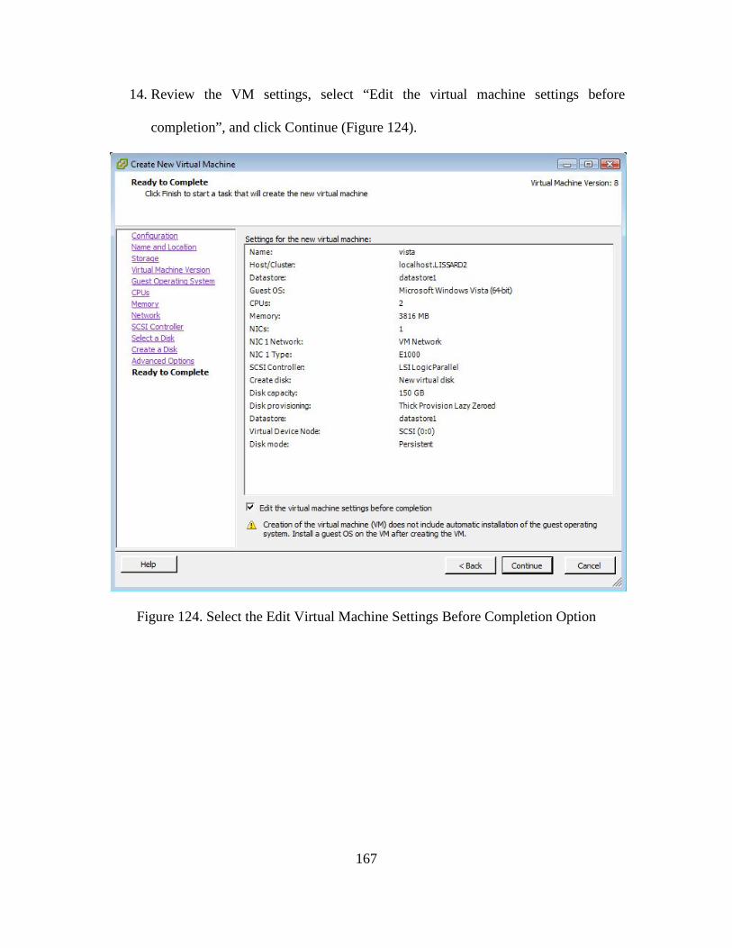
167
14. Review the VM settings, select “Edit the virtual machine settings before
completion”, and click Continue (Figure 124).
Figure 124. Select the Edit Virtual Machine Settings Before Completion Option
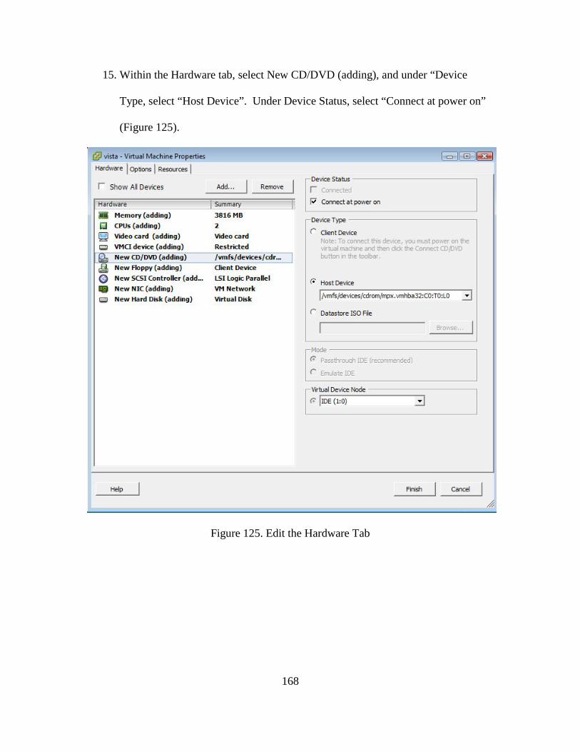
168
15. Within the Hardware tab, select New CD/DVD (adding), and under “Device
Type, select “Host Device”. Under Device Status, select “Connect at power on”
(Figure 125).
Figure 125. Edit the Hardware Tab
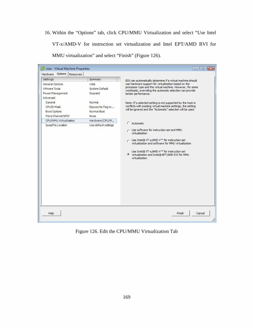
169
16. Within the “Options” tab, click CPU/MMU Virtualization and select “Use Intel
VT-x/AMD-V for instruction set virtualization and Intel EPT/AMD RVI for
MMU virtualization” and select “Finish” (Figure 126).
Figure 126. Edit the CPU/MMU Virtualization Tab
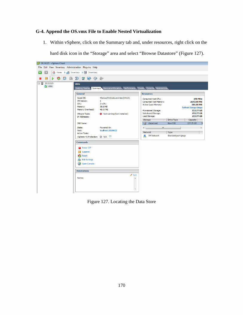
170
G-4. Append the OS.vmx File to Enable Nested Virtualization
1. Within vSphere, click on the Summary tab and, under resources, right click on the
hard disk icon in the “Storage” area and select “Browse Datastore” (Figure 127).
Figure 127. Locating the Data Store
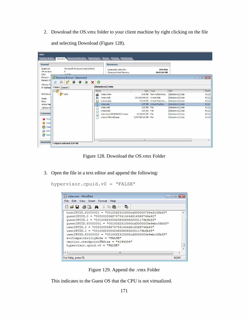
171
2. Download the OS.vmx folder to your client machine by right clicking on the file
and selecting Download (Figure 128).
Figure 128. Download the OS.vmx Folder
3. Open the file in a text editor and append the following:
hypervisor.cpuid.v0 = “FALSE”
Figure 129. Append the .vmx Folder
This indicates to the Guest OS that the CPU is not virtualized.
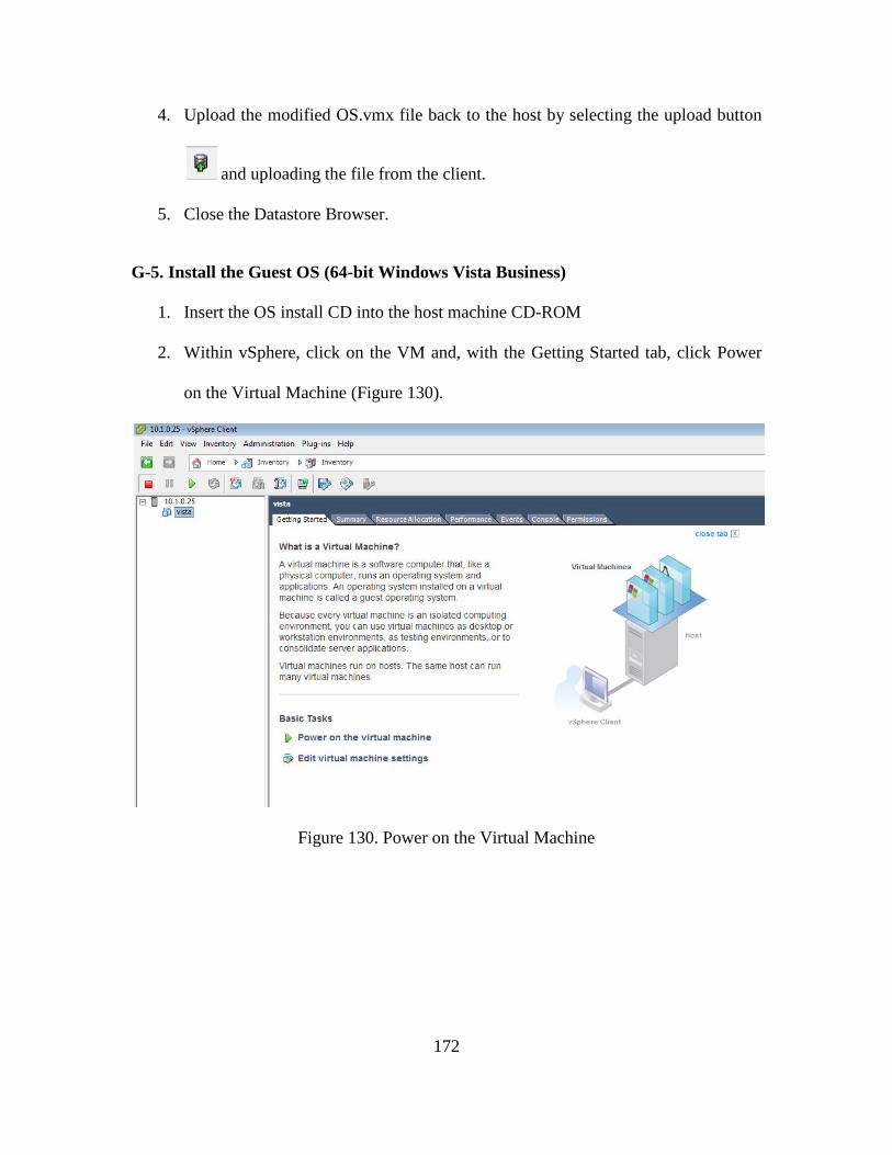
172
4. Upload the modified OS.vmx file back to the host by selecting the upload button
and uploading the file from the client.
5. Close the Datastore Browser.
G-5. Install the Guest OS (64-bit Windows Vista Business)
1. Insert the OS install CD into the host machine CD-ROM
2. Within vSphere, click on the VM and, with the Getting Started tab, click Power
on the Virtual Machine (Figure 130).
Figure 130. Power on the Virtual Machine
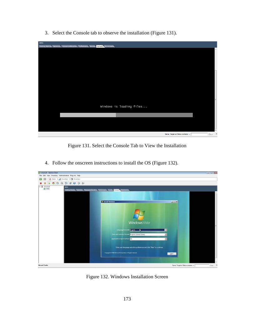
173
3. Select the Console tab to observe the installation (Figure 131).
Figure 131. Select the Console Tab to View the Installation
4. Follow the onscreen instructions to install the OS (Figure 132).
Figure 132. Windows Installation Screen
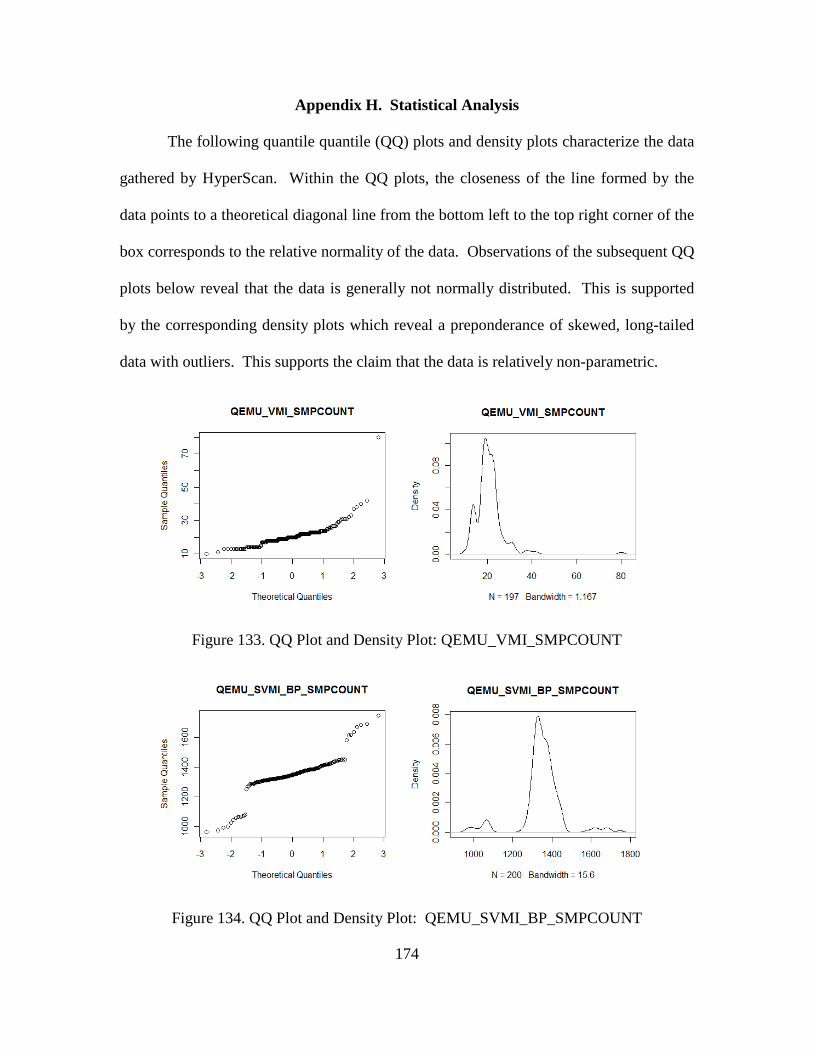
174
Appendix H. Statistical Analysis
The following quantile quantile (QQ) plots and density plots characterize the data
gathered by HyperScan. Within the QQ plots, the closeness of the line formed by the
data points to a theoretical diagonal line from the bottom left to the top right corner of the
box corresponds to the relative normality of the data. Observations of the subsequent QQ
plots below reveal that the data is generally not normally distributed. This is supported
by the corresponding density plots which reveal a preponderance of skewed, long-tailed
data with outliers. This supports the claim that the data is relatively non-parametric.
Figure 133. QQ Plot and Density Plot: QEMU_VMI_SMPCOUNT
Figure 134. QQ Plot and Density Plot: QEMU_SVMI_BP_SMPCOUNT
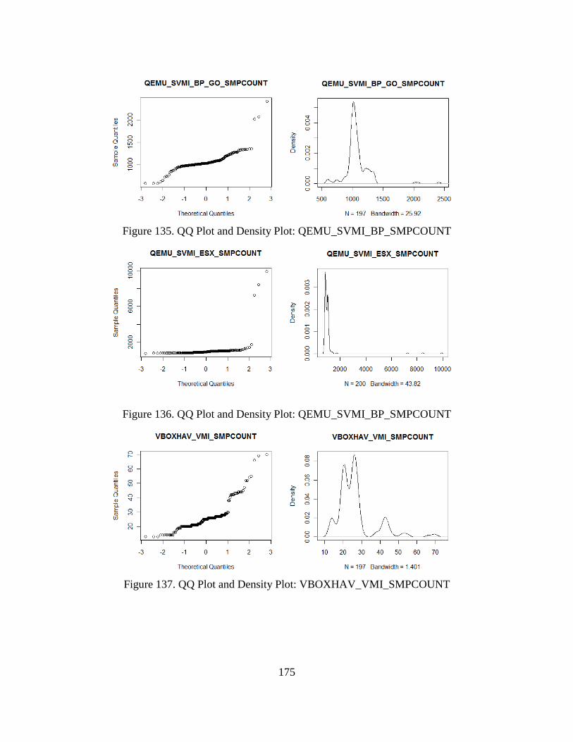
175
Figure 135. QQ Plot and Density Plot: QEMU_SVMI_BP_SMPCOUNT
Figure 136. QQ Plot and Density Plot: QEMU_SVMI_BP_SMPCOUNT
Figure 137. QQ Plot and Density Plot: VBOXHAV_VMI_SMPCOUNT
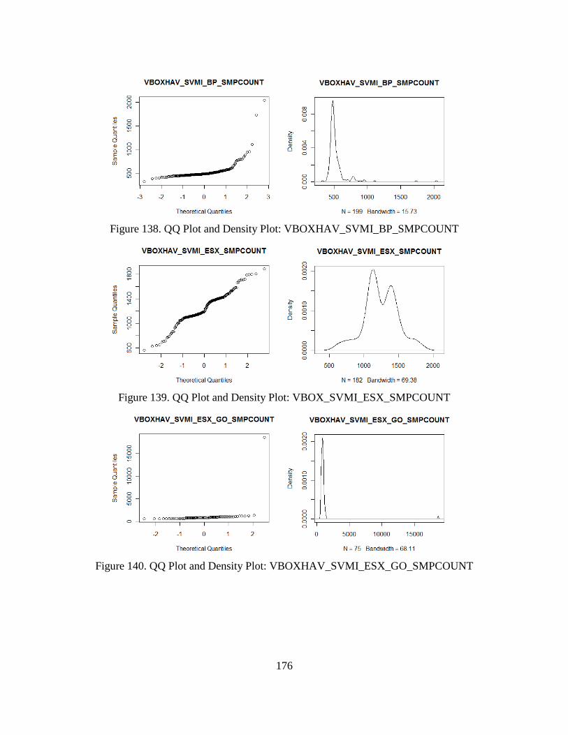
176
Figure 138. QQ Plot and Density Plot: VBOXHAV_SVMI_BP_SMPCOUNT
Figure 139. QQ Plot and Density Plot: VBOX_SVMI_ESX_SMPCOUNT
Figure 140. QQ Plot and Density Plot: VBOXHAV_SVMI_ESX_GO_SMPCOUNT
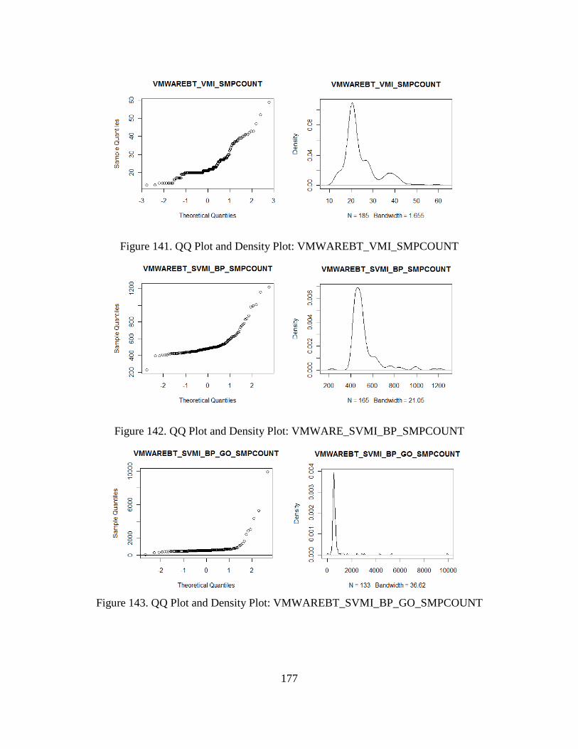
177
Figure 141. QQ Plot and Density Plot: VMWAREBT_VMI_SMPCOUNT
Figure 142. QQ Plot and Density Plot: VMWARE_SVMI_BP_SMPCOUNT
Figure 143. QQ Plot and Density Plot: VMWAREBT_SVMI_BP_GO_SMPCOUNT
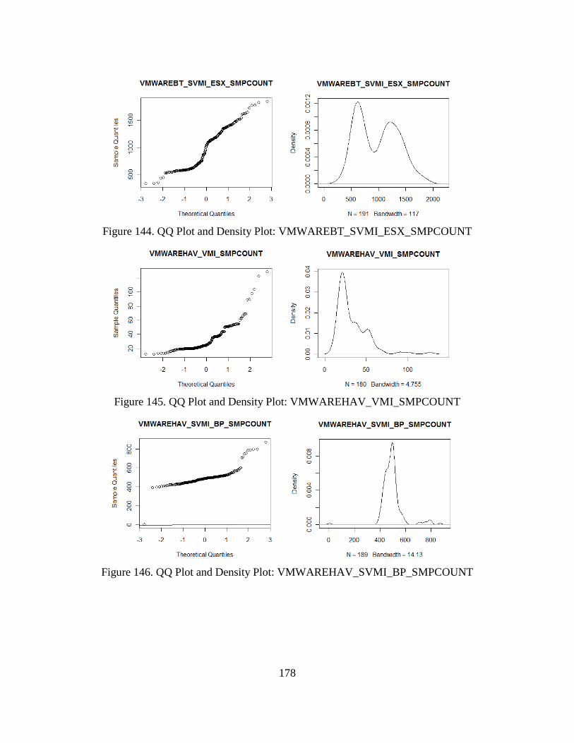
178
Figure 144. QQ Plot and Density Plot: VMWAREBT_SVMI_ESX_SMPCOUNT
Figure 145. QQ Plot and Density Plot: VMWAREHAV_VMI_SMPCOUNT
Figure 146. QQ Plot and Density Plot: VMWAREHAV_SVMI_BP_SMPCOUNT
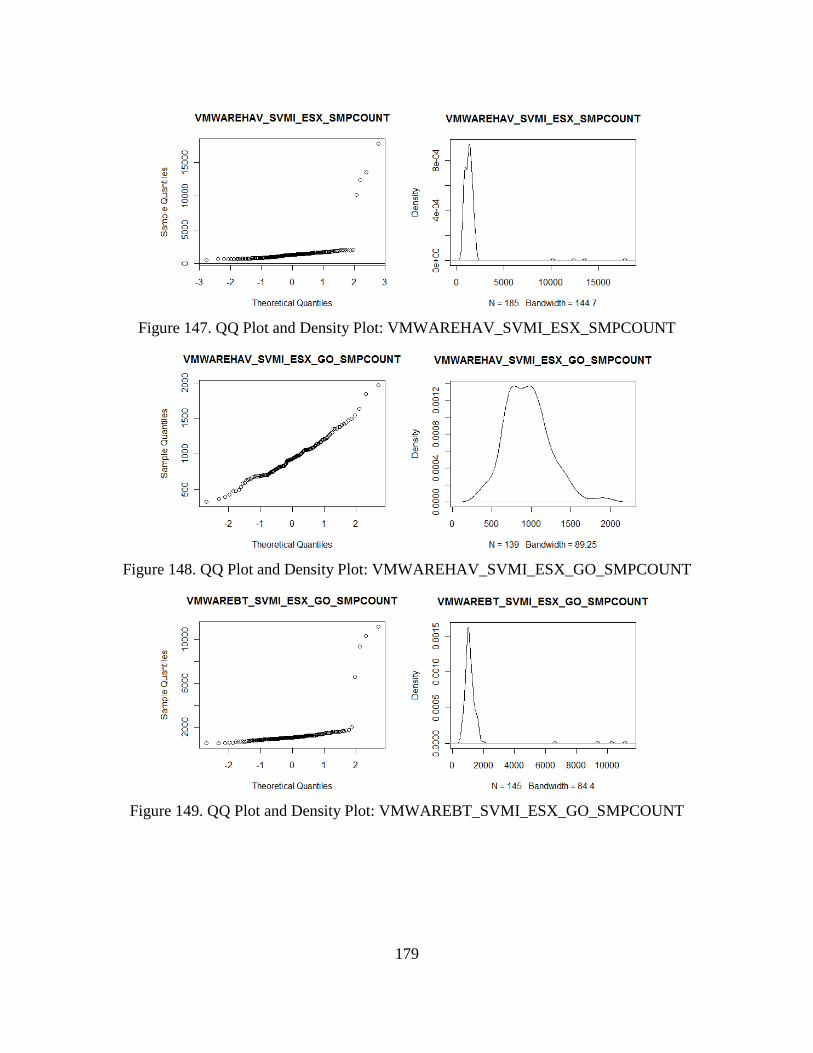
179
Figure 147. QQ Plot and Density Plot: VMWAREHAV_SVMI_ESX_SMPCOUNT
Figure 148. QQ Plot and Density Plot: VMWAREHAV_SVMI_ESX_GO_SMPCOUNT
Figure 149. QQ Plot and Density Plot: VMWAREBT_SVMI_ESX_GO_SMPCOUNT
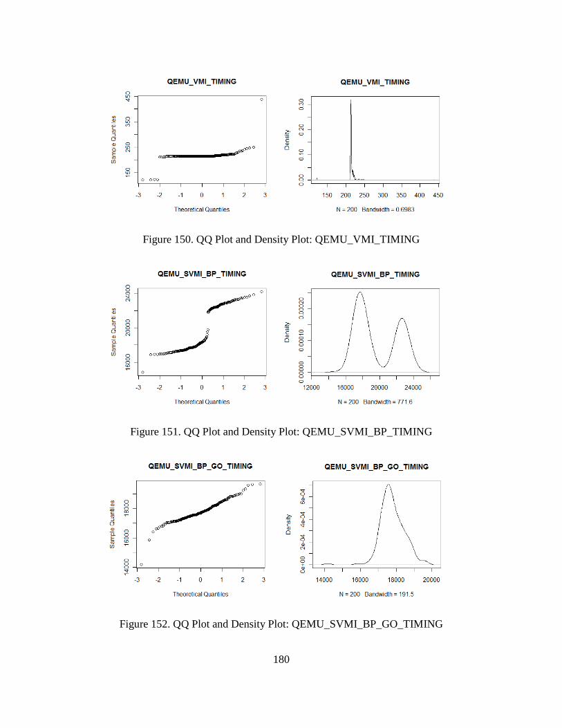
180
Figure 150. QQ Plot and Density Plot: QEMU_VMI_TIMING
Figure 151. QQ Plot and Density Plot: QEMU_SVMI_BP_TIMING
Figure 152. QQ Plot and Density Plot: QEMU_SVMI_BP_GO_TIMING
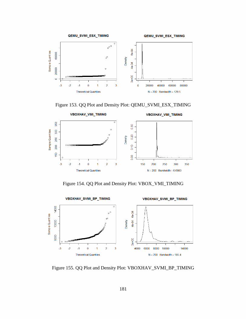
181
Figure 153. QQ Plot and Density Plot: QEMU_SVMI_ESX_TIMING
Figure 154. QQ Plot and Density Plot: VBOX_VMI_TIMING
Figure 155. QQ Plot and Density Plot: VBOXHAV_SVMI_BP_TIMING
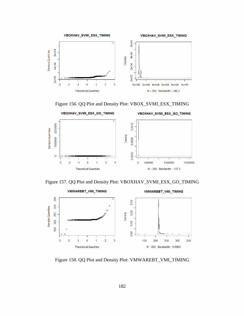
182
Figure 156. QQ Plot and Density Plot: VBOX_SVMI_ESX_TIMING
Figure 157. QQ Plot and Density Plot: VBOXHAV_SVMI_ESX_GO_TIMING
Figure 158. QQ Plot and Density Plot: VMWAREBT_VMI_TIMING
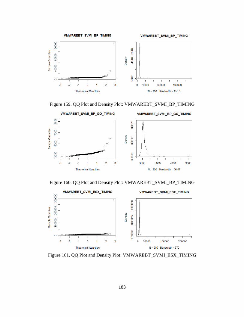
183
Figure 159. QQ Plot and Density Plot: VMWAREBT_SVMI_BP_TIMING
Figure 160. QQ Plot and Density Plot: VMWAREBT_SVMI_BP_TIMING
Figure 161. QQ Plot and Density Plot: VMWAREBT_SVMI_ESX_TIMING
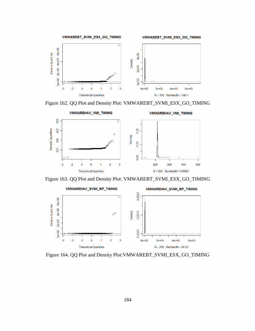
184
Figure 162. QQ Plot and Density Plot: VMWAREBT_SVMI_ESX_GO_TIMING
Figure 163. QQ Plot and Density Plot: VMWAREBT_SVMI_ESX_GO_TIMING
Figure 164. QQ Plot and Density Plot:VMWAREBT_SVMI_ESX_GO_TIMING
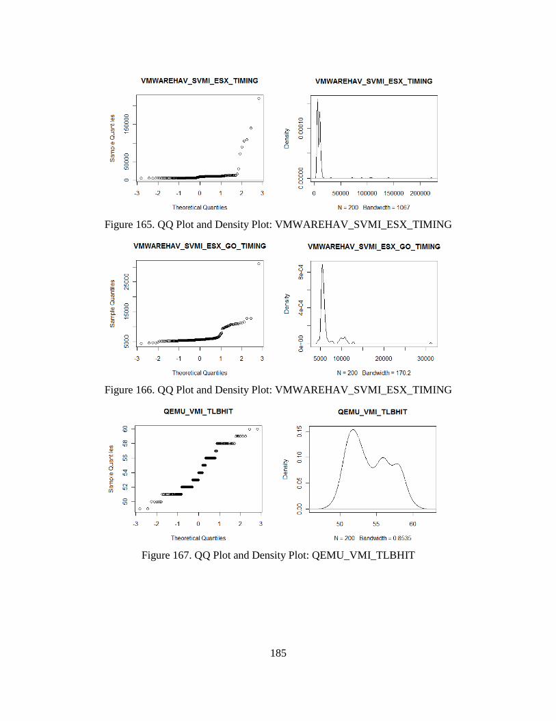
185
Figure 165. QQ Plot and Density Plot: VMWAREHAV_SVMI_ESX_TIMING
Figure 166. QQ Plot and Density Plot: VMWAREHAV_SVMI_ESX_TIMING
Figure 167. QQ Plot and Density Plot: QEMU_VMI_TLBHIT
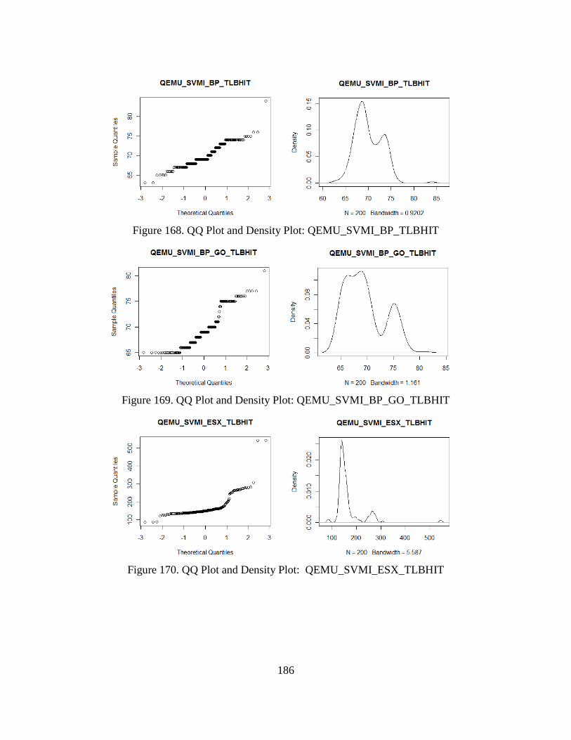
186
Figure 168. QQ Plot and Density Plot: QEMU_SVMI_BP_TLBHIT
Figure 169. QQ Plot and Density Plot: QEMU_SVMI_BP_GO_TLBHIT
Figure 170. QQ Plot and Density Plot: QEMU_SVMI_ESX_TLBHIT
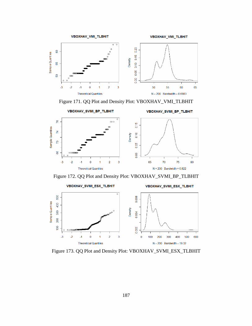
187
Figure 171. QQ Plot and Density Plot: VBOXHAV_VMI_TLBHIT
Figure 172. QQ Plot and Density Plot: VBOXHAV_SVMI_BP_TLBHIT
Figure 173. QQ Plot and Density Plot: VBOXHAV_SVMI_ESX_TLBHIT
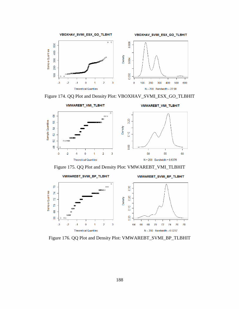
188
Figure 174. QQ Plot and Density Plot: VBOXHAV_SVMI_ESX_GO_TLBHIT
Figure 175. QQ Plot and Density Plot: VMWAREBT_VMI_TLBHIT
Figure 176. QQ Plot and Density Plot: VMWAREBT_SVMI_BP_TLBHIT
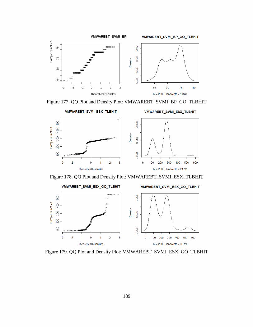
189
Figure 177. QQ Plot and Density Plot: VMWAREBT_SVMI_BP_GO_TLBHIT
Figure 178. QQ Plot and Density Plot: VMWAREBT_SVMI_ESX_TLBHIT
Figure 179. QQ Plot and Density Plot: VMWAREBT_SVMI_ESX_GO_TLBHIT
-3 -2 -1 0 1 2 3
6468
7276
VMWAREBT_SVMI_BP_
Theoretical Quantiles
Sam
ple
Qua
ntile
s
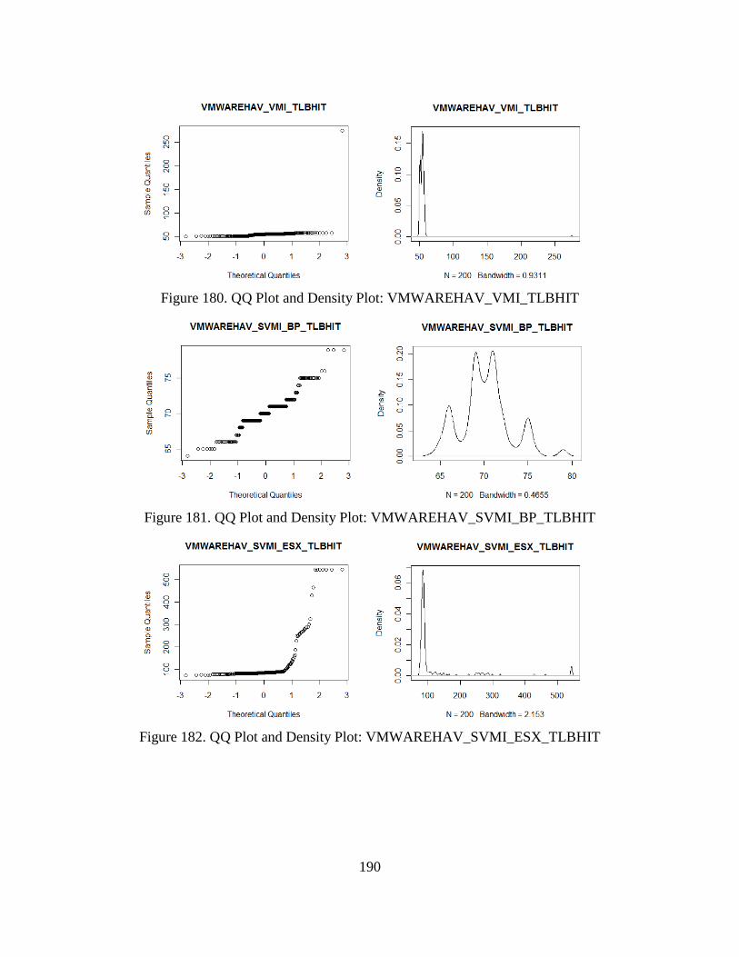
190
Figure 180. QQ Plot and Density Plot: VMWAREHAV_VMI_TLBHIT
Figure 181. QQ Plot and Density Plot: VMWAREHAV_SVMI_BP_TLBHIT
Figure 182. QQ Plot and Density Plot: VMWAREHAV_SVMI_ESX_TLBHIT
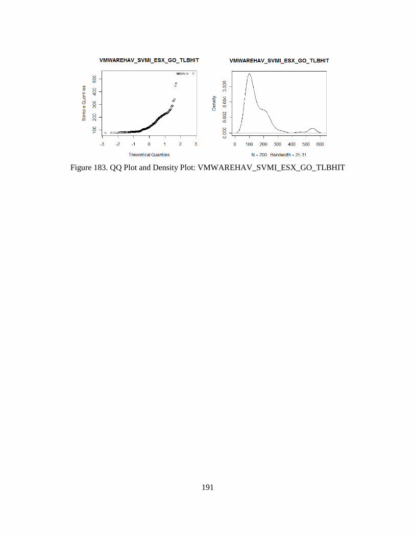
191
Figure 183. QQ Plot and Density Plot: VMWAREHAV_SVMI_ESX_GO_TLBHIT
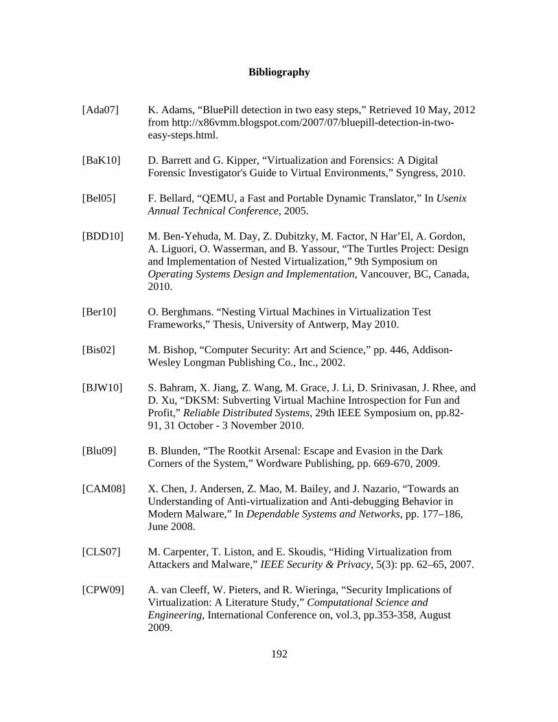
192
Bibliography
[Ada07] K. Adams, “BluePill detection in two easy steps,” Retrieved 10 May, 2012 from http://x86vmm.blogspot.com/2007/07/bluepill-detection-in-two-easy-steps.html.
[BaK10] D. Barrett and G. Kipper, “Virtualization and Forensics: A Digital Forensic Investigator's Guide to Virtual Environments,” Syngress, 2010.
[Bel05] F. Bellard, “QEMU, a Fast and Portable Dynamic Translator,” In Usenix Annual Technical Conference, 2005.
[BDD10] M. Ben-Yehuda, M. Day, Z. Dubitzky, M. Factor, N Har’El, A. Gordon, A. Liguori, O. Wasserman, and B. Yassour, “The Turtles Project: Design and Implementation of Nested Virtualization,” 9th Symposium on Operating Systems Design and Implementation, Vancouver, BC, Canada, 2010.
[Ber10] O. Berghmans. “Nesting Virtual Machines in Virtualization Test Frameworks,” Thesis, University of Antwerp, May 2010.
[Bis02] M. Bishop, “Computer Security: Art and Science,” pp. 446, Addison-Wesley Longman Publishing Co., Inc., 2002.
[BJW10] S. Bahram, X. Jiang, Z. Wang, M. Grace, J. Li, D. Srinivasan, J. Rhee, and D. Xu, “DKSM: Subverting Virtual Machine Introspection for Fun and Profit,” Reliable Distributed Systems, 29th IEEE Symposium on, pp.82-91, 31 October - 3 November 2010.
[Blu09] B. Blunden, “The Rootkit Arsenal: Escape and Evasion in the Dark Corners of the System,” Wordware Publishing, pp. 669-670, 2009.
[CAM08] X. Chen, J. Andersen, Z. Mao, M. Bailey, and J. Nazario, “Towards an Understanding of Anti-virtualization and Anti-debugging Behavior in Modern Malware,” In Dependable Systems and Networks, pp. 177–186, June 2008.
[CLS07] M. Carpenter, T. Liston, and E. Skoudis, “Hiding Virtualization from Attackers and Malware,” IEEE Security & Privacy, 5(3): pp. 62–65, 2007.
[CPW09] A. van Cleeff, W. Pieters, and R. Wieringa, “Security Implications of Virtualization: A Literature Study,” Computational Science and Engineering, International Conference on, vol.3, pp.353-358, August 2009.
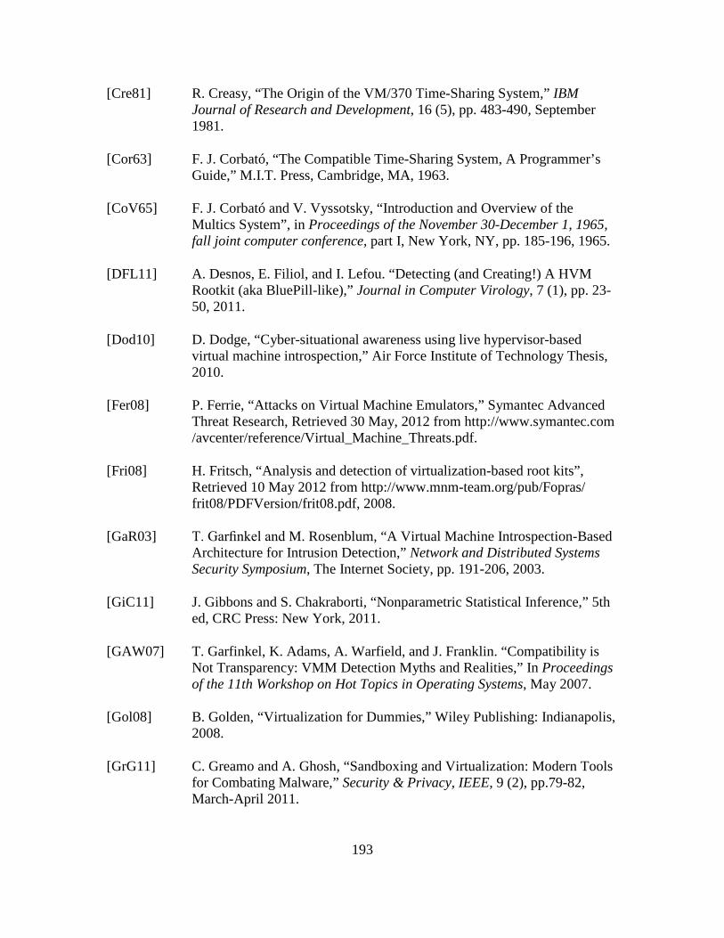
193
[Cre81] R. Creasy, “The Origin of the VM/370 Time-Sharing System,” IBM Journal of Research and Development, 16 (5), pp. 483-490, September 1981.
[Cor63] F. J. Corbató, “The Compatible Time-Sharing System, A Programmer’s Guide,” M.I.T. Press, Cambridge, MA, 1963.
[CoV65] F. J. Corbató and V. Vyssotsky, “Introduction and Overview of the Multics System”, in Proceedings of the November 30-December 1, 1965, fall joint computer conference, part I, New York, NY, pp. 185-196, 1965.
[DFL11] A. Desnos, E. Filiol, and I. Lefou. “Detecting (and Creating!) A HVM Rootkit (aka BluePill-like),” Journal in Computer Virology, 7 (1), pp. 23-50, 2011.
[Dod10] D. Dodge, “Cyber-situational awareness using live hypervisor-based virtual machine introspection,” Air Force Institute of Technology Thesis, 2010.
[Fer08] P. Ferrie, “Attacks on Virtual Machine Emulators,” Symantec Advanced Threat Research, Retrieved 30 May, 2012 from http://www.symantec.com /avcenter/reference/Virtual_Machine_Threats.pdf.
[Fri08] H. Fritsch, “Analysis and detection of virtualization-based root kits”, Retrieved 10 May 2012 from http://www.mnm-team.org/pub/Fopras/ frit08/PDFVersion/frit08.pdf, 2008.
[GaR03] T. Garfinkel and M. Rosenblum, “A Virtual Machine Introspection-Based Architecture for Intrusion Detection,” Network and Distributed Systems Security Symposium, The Internet Society, pp. 191-206, 2003.
[GiC11] J. Gibbons and S. Chakraborti, “Nonparametric Statistical Inference,” 5th ed, CRC Press: New York, 2011.
[GAW07] T. Garfinkel, K. Adams, A. Warfield, and J. Franklin. “Compatibility is Not Transparency: VMM Detection Myths and Realities,” In Proceedings of the 11th Workshop on Hot Topics in Operating Systems, May 2007.
[Gol08] B. Golden, “Virtualization for Dummies,” Wiley Publishing: Indianapolis, 2008.
[GrG11] C. Greamo and A. Ghosh, “Sandboxing and Virtualization: Modern Tools for Combating Malware,” Security & Privacy, IEEE, 9 (2), pp.79-82, March-April 2011.
194
[HeA11] X. He and J. Alves-Foss, “A lightweight virtual machine monitor for security analysis on Intel64 architecture,” Journal of Computing Sciences in Colleges. 27 (1), pp. 155-162, October 2011.
[HoB05] G. Hoglund, and J. Butler, Rootkits: Subverting the Windows Kernel. Addison-Wesley, 2005.
[HHK09] L. Holmqvist, T. Halbach, and T Kristoffersen, "Virtualization as a strategy for maintaining future access to multimedia content," Advances in Multimedia, First International Conference on, pp.29-32, 20-25 July 2009.
[IBM11] Mainframe Product Profiles: System/370 Model 138, Retrieved 10 May 2012 from http://www-03.ibm.com/ibm/history/exhibits/mainframe/ mainframe_PP3138.html.
[IEE11] OUI Public Listing, Retrieved 2 November 2011 from http://standards. ieee.org/develop/regauth/oui/index.html.
[JML10] S. Jyotiprakash, S. Mohapatra and R. Lath, "Virtualization: A Survey on Concepts, Taxonomy and Associated Security Issues," Second International Conference on Computer and Network Technology, pp. 222-226, 2010.
[KaS11] S. Karnouskos and A. Colombo, “Architecting the next generation of service-based SCADA/DCS system of systems,” in 37th Annual Conference of the IEEE Industrial Electronics Society, Melbourne, Australia., 7-10 November 2011.
[KCW06] S. King, M. Chen, Y. Wang, C. Verbowski, H.Wang, and J. Lorch, “SubVirt: Implementing Malware with Virtual Machines,” In Proceedings of the 2006 IEEE Symposium on Security and Privacy, May 2006.
[Kir07] J. Kirch, “Virtual machine security guidelines,” Retrieved 10 May 2012 from http://www.cisecurity.org/tools2/vm/CIS_VM_Benchmark_v1.0.pdf.
[Kli11] T. Klein. “Scoopyng - the vmware detection tool,” Retrieved 10 May 2012 from http://www.trapkit.de/research/vmm/scoopyng/index.html.
[Kor09] K. Kortchinsky. “Cloudburst—a VMware Guest to host escape story,” Retrieved 10 May 2012 from http://www.blackhat.com/presentations/bh-usa-09/KORTCHINSKY/BHUSA09-Kortchinsky-Cloudburst-SLIDES.pdf.
[KVM12] “Kernel-based Virtual Machine,” Retrieved 10 May 2012 from http://www.linux-kvm.org/page/Main_Page.
195
[LeM08] M. Lessing, “Live forensic acquisition as alternative to traditional forensic processes,” IMF Conference, September 2008.
[LiS06] T. Liston and E. Skoudis, “On the Cutting Edge: Thwarting Virtual MachineDetection,” Retrieved 10 May 2012 from http://handlers.sans.org/ tliston/ThwartingVMDetection_Liston Skoudis.pdf
[LuC00] C. Lunneborg, Data analysis by resampling: concepts and applications, pp 261-271, Pacific Grove: Duxbury Press, 2000.
[MoE02] D. Mosberger and S. Eranian, IA-64 Linux Kernel: Design and Implementation, Prentice Hall, 2002.
[MSN12] Kernel-Mode Code Signing Walkthrough, Retrieved 1 February 2012 from http://msdn.microsoft.com/en-us/windows/hardware/gg487328.
[MyY07] M. Myers and S. Youndt, “An Introduction to Hardware-Assisted Virtual Machine (HVM) Rootkits,” Technical Report, Retrieved 10 May 2012 from http://www.megasecurity.org/papers/hvmrootkits.pdf.
[NBH08] K. Nance, M. Bishop, and B. Hay, “Virtual Machine Introspection: Observation or Interference?” Security & Privacy, IEEE, 6 (5), pp.32-37, Sept.-Oct. 2008.
[NHB09] K. Nance, B. Hay, and M. Bishop, "Investigating the Implications of Virtual Machine Introspection for Digital Forensics," Availability, Reliability and Security, International Conference on , pp.1024-1029, 16-19 March 2009.
[NSL06] G. Neiger, A Santoni, F. Leung, D. Rodgers, and R Uhlig, “Intel virtualization technology: Hardware support for efficient processor virtualization,” Intel Technology Journal, 10 (3), 2006.
[Ome06] A. Omella, “Methods for virtual machine detection,” Retrieved 1 June 2011 from www.s21sec.com/descargas/vmware-eng.pdf.
[Ora12] Oracle Corporation, “Oracle VM VirtualBox User Manual,” Retrieved 10 May 2012 from http://www.virtualbox.org/manual/.
[QuS05] D. Quist and V. Smith. “Detecting the presence of virtual machines using the local data table,” Retrieved 10 May 2012 from http://www. offensivecomputing.net/dc14/vm.pdf.
196
[PoG74] G. J. Popek and R. P. Goldberg, “Formal Requirements for Virtualizable Third Generation Architectures,” Communications of the ACM, 17 (7), pp 412 – 421, July 1974.
[RoG05] M. Rosenblum and T. Garfinkel, "Virtual machine monitors: current technology and future trends," Computer, 38 (5), pp. 39 - 47, May 2005.
[RuC05] A. Rubini and J. Corbet, “Linux Device Drivers,” third ed. O’Reilly, 2005.
[Rut04] J. Rutkowska, “Red pill...or how to detect vmm using one cpu instruction,” Retrieved 10 May 2012 from http://invisiblethings.org/ papers/redpill.html.
[RuT07a] J. Rutkowska and A. Tereshkin, “IsGameOver() Anyone?” Retrieved 10 May 2012 from http://invisiblethingslab.com/resources/bh07/IsGame Over.pdf, 17 February 2012.
[Rut07b] J. Rutkowska, Resources, Retrieved 13 December 2011 from http://invisiblethingslab.com/resources/bh07/.
[San09] Sandia Labs, “Sandia computer scientists successfully boot one million Linux kernels as virtual machines,” Retrieved 10 May 2012 from https://share.sandia.gov/news/resources/news_releases/sandia-computer-scientists-successfully-boot-one-million-linux-kernels-as-virtual-machines.
[SaS05] S. Sawilowsky, “Misconceptions leading to choosing the t test over the Wilcoxon Mann-Whitney Test for Shift in Location Parameter,” Journal of Modern Applied Statistical Methods 4 (2), pp 598-600, 2005.
[Sch08] B. Schneier, “Schneier on Security,” Wiley Computer Publishing, 2008.
[She05] T. Shelton, “VMware NAT Networking Buffer Overflow Vulnerability,” Retrieved 19 January 2012 from http://lists.grok.org.uk/pipermail/full-disclosure/2005-december/040442.html.
[SPF07] S. Soltesz, H. Potzl, M. Fiuczynski, A. Bavier, and L. Peterson, “Container-based operating system virtualization: A scalable, high-performance alternative to hypervisors,” In Proc. EuroSys, pp 275–287, 2007.
[TrH09] R. Troy and M. Helmke, “VMware cookbook,” Sebastopol, California: O’Reilly Media Inc, 2009.
197
[USB11] U.S. Bureau of Labor Statistics, CPI Inflation Calculator, Retrieved 10 May 2012 from http://www.bls.gov/data/inflation_calculator.html.
[VuA11] S. Vuong and M. Alam, “Advanced Methods for Botnet Intrusion Detection Systems,” Intrusion Detection Systems, Retrieved 10 May 2012 from http://www.intechopen.com/articles/show/title/advanced-methods-for-botnet-intrusion-detection-systems.
[VPM11] K. Vishnani, A. Pais, and R. Mohandas, “Detecting and Defeating Split Personality Malware,” The Fifth International Conference on Emerging Security Information, Systems and Technologies, Nice/Saint Laurent du Var, France, 21 August, 2011.
[VMW12] VMware, “ESXi and ESX Architectures Compared”, Retrieved 10 May 2012 from http://www.vmware.com/products/vsphere/esxi-and-esx/compare.html.
[ZhC07] D. Zhu and E. Chin, “Detection of VM-Aware Malware,” Retrieved 10 May 2012 from http://radlab.cs.berkeley.edu/w/uploads/3/3d/Detecting_ VM_Aware_Malware.pdf.
198
REPORT DOCUMENTATION PAGE Form Approved OMB No. 074-0188
The public reporting burden for this collection of information is estimated to average 1 hour per response, including the time for reviewing instructions, searching existing data sources, gathering and maintaining the data needed, and completing and reviewing the collection of information. Send comments regarding this burden estimate or any other aspect of the collection of information, including suggestions for reducing this burden to Department of Defense, Washington Headquarters Services, Directorate for Information Operations and Reports (0704-0188), 1215 Jefferson Davis Highway, Suite 1204, Arlington, VA 22202-4302. Respondents should be aware that notwithstanding any other provision of law, no person shall be subject to an penalty for failing to comply with a collection of information if it does not display a currently valid OMB control number. PLEASE DO NOT RETURN YOUR FORM TO THE ABOVE ADDRESS. 1. REPORT DATE (DD-MM-YYYY)
14-06-2012 2. REPORT TYPE
Master’s Thesis 3. DATES COVERED (From – To)
August 2010 – June 2012
TITLE AND SUBTITLE Detecting Hardware-assisted Hypervisor Rootkits within Nested Virtualized Environments
5a. CONTRACT NUMBER
5b. GRANT NUMBER 5c. PROGRAM ELEMENT NUMBER
6. AUTHOR(S) Morabito, Daniel B., Captain
5d. PROJECT NUMBER
5e. TASK NUMBER
5f. WORK UNIT NUMBER
7. PERFORMING ORGANIZATION NAMES(S) AND ADDRESS(S) Air Force Institute of Technology Graduate School of Engineering and Management (AFIT/ENY) 2950 Hobson Way, Building 640 WPAFB OH 45433-8865
8. PERFORMING ORGANIZATION REPORT NUMBER AFIT/GCO/ENG/12-20
9. SPONSORING/MONITORING AGENCY NAME(S) AND ADDRESS(ES) Air Force Research Laboratory, Information Grid Division/ Cyber Science Branch Attn: Joe Carozzoni 26 Electronic Parkway Rome, NY 13441-4514 (315) 330-3459 (DSN:587-7796)
10. SPONSOR/MONITOR’S ACRONYM(S) AFRL/RIGG 11. SPONSOR/MONITOR’S REPORT NUMBER(S)
12. DISTRIBUTION/AVAILABILITY STATEMENT APPROVED FOR PUBLIC RELEASE; DISTRIBUTION UNLIMITED. 13. SUPPLEMENTARY NOTES This material is declared a work of the U.S. Government and is not subject to copyright protection in the United States. 14. ABSTRACT Virtual machine introspection (VMI) is intended to provide a secure and trusted platform from which forensic information can be gathered about the true behavior of malware within a guest. However, it is possible for malware to escape a guest into the host and for hypervisor rootkits, such as BluePill, to stealthily transition a native OS into a virtualized environment. This research examines the effectiveness of selected detection mechanisms against hardware-assisted virtualization rootkits (HAV-R) within a nested virtualized environment. It presents the design, implementation, analysis, and evaluation of a hypervisor rootkit detection system which exploits both processor and translation lookaside buffer-based mechanisms to detect hypervisor rootkits within a variety of nested virtualized systems. It evaluates the effects of different types of virtualization on hypervisor rootkit detection and explores the effectiveness in-guest HAV-R obfuscation efforts. The results provide convincing evidence that the HAV-Rs are detectable in all SVMI scenarios examined, regardless of HAV-R or virtualization type. Also, that the selected detection techniques are effective at detection of HAV-R within nested virtualized environments, and that the type of virtualization implemented in a VMI system has minimal to no effect on HAV-R detection. Finally, it is determined that in-guest obfuscation does not successfully obfuscate the existence of HAV-R. 15. SUBJECT TERMS Hypervisor, Rootkit, Nested Virtualization, Detection, Evasion, Subversion, Virtual Machine Introspection, BluePill 16. SECURITY CLASSIFICATION OF:
17. LIMITATION OF ABSTRACT
UU
18. NUMBER OF PAGES
219
19a. NAME OF RESPONSIBLE PERSON Dr. Barry E. Mullins
a. REPORT
U
b. ABSTRACT
U
c. THIS PAGE
U
19b. TELEPHONE NUMBER (Include area code) (937) 255-3636, ext 7979 ([email protected])
Standard Form 298 (Rev. 8-98) Prescribed by ANSI Std. Z39-18