Embed Size (px)
Citation preview
i
Aerial Ice Dam Control & Removal
Major Qualifying Project Report
Project: JMS-1604
Submitted to the Faculty
of the
WORCESTER POLYTECHNIC INSTITUTE
in partial fulfillment of the requirements for the
Degree of Bachelor of Science in Mechanical Engineering
By:
Stephen Arata
Riley Shoneck
Mitchell Weeks
Advisor: Professor John M. Sullivan Jr.
25 March 2015
ii
Abstract
Ice dams can cause serious damage to homes during the wintertime. A multirotor
mounted solution was sought to drop salt on these ice dams, allowing backed-up water to flow
through and prevent water damage. Two mechanisms were developed and prototyped. The
prototypes had rapid interchangeability and a unified static multirotor mount. They were created
with rapid prototyping technology for quick assembly and repair, with the majority of parts
composed of lightweight laser-cut acrylic and 3D-printed PLA. One mechanism carries and
deploys 0.7 kg of standard calcium chloride throw-able ice pucks, while the other carries drops
1.239 kg of granular pet-safe ice melt. They are both controlled manually by the same
transmitter/receiver system (tested to a line-of-sight range of over 450m), which is independent
of the multirotor flight control system. Both mechanisms perform as intended, and jams are
clearable using the transmitter.
iii
Acknowledgements
Firstly, we would like to thank our advisor, Professor Sullivan. He kept us on-task and
always cognizant of the practical considerations we may have otherwise overlooked.
Secondly, Joseph St Germain in the Robotics Engineering department proved
instrumental in helping with the multirotor aspect of the project. The feasibility of many
multirotors and the workings of our electronics (specifically, the transmitter and receiver) went
through him first. He also assisted in the procurement of motors and miscellaneous other
hardware that we incorporated into the final designs.
Finally, Gregory Tighe, an undergraduate in the Robotics Engineering department, kindly
allowed us to survey the S1000+ multirotor that his MQP used as a vehicle. We were able to
obtain measurements and a working components list with his assistance.

iv
Authorship
All sections were written and edited jointly by all members.
v
Contents
Abstract....................................................................................................................................... ii
Acknowledgements .................................................................................................................... iii
Authorship .................................................................................................................................. iv
Contents ..................................................................................................................................... v
Table of Figures ....................................................................................................................... viii
Table of Tables .......................................................................................................................... ix
Executive Summary .................................................................................................................... x
Terminology ............................................................................................................................... xi
1.0 Introduction .......................................................................................................................... 1
2.0 Identification of Need ........................................................................................................... 4
3.0 Background Research .......................................................................................................... 5
3.1 Ice Dams and Their Effects............................................................................................... 5
3.2 Ice Dam Prevention, Control, and Removal ...................................................................... 6
3.2.1 Ice Dam Prevention .................................................................................................... 6
3.2.2 Ice Dam Mitigation ....................................................................................................10
3.2.3 Ice Dam Removal ......................................................................................................13
3.3 Multirotors ........................................................................................................................15
3.3.1 DJI Phantom 3 ..........................................................................................................16
3.3.2 3D Robotics X8+ .......................................................................................................17
3.3.3 DJI S900 ...................................................................................................................18
3.3.4 DJI S1000+ ...............................................................................................................19
3.3.5 Feasibility of Select Multirotor Modifications ..............................................................20
3.3.6 Legality of Multirotor Use ...........................................................................................21
4.0 Goal Statement ...................................................................................................................23
5.0 Task Specifications .............................................................................................................23
6.0 Development of Preliminary Designs...................................................................................24
6.1 Preliminary Designs .........................................................................................................24
6.1.1 Design 1 - Vertical Tube with Shelves .......................................................................24
6.2.2 Design 2 - Swivel Arm ...............................................................................................26
6.2.3 Design 3 - Crank-Slider .............................................................................................27
6.2.4 Design 4 - Rack and Pinion .......................................................................................28
vi
6.2.5 Design 5 - Turntable ..................................................................................................29
6.2.6 Design 6 - Turbo Puck Release .................................................................................30
6.2.7 Design 7 - CD Changer .............................................................................................31
6.2.8 Design 8 - Granular Funnel .......................................................................................33
6.2 Weighted Design Matrix ...................................................................................................34
7.0 Selection of Final Designs ...................................................................................................37
7.1 Constraints ......................................................................................................................37
7.2 Selection of Materials and Fasteners ...............................................................................41
7.2.1 Material Selection ......................................................................................................41
7.2.2 Rapid Prototyping ......................................................................................................42
7.2.3 Fastener Selection ....................................................................................................42
7.3 Inclusion of Motors and Electronic Components ..............................................................42
7.4 Mounting Mechanisms to the Multirotor ...........................................................................43
7.4.1 Design of the Multirotor Mounting Units .....................................................................43
7.4.2 Design of the Generic Rectangular Mounting Plate ...................................................44
7.4.3 Finite Element Analysis of the Mounting Units ...........................................................45
7.5 Development of the Puck Mechanism Final Design .........................................................48
7.5.1 General Description of Purpose ................................................................................48
7.5.2 Determining a Mass Limit for the Mechanism ............................................................48
7.5.3 Design Development/Construction ............................................................................49
7.5.4 How the Puck Mechanism Works ..............................................................................55
7.5.5 Customization of the Mounting Plate .........................................................................58
7.5.6 Description of the Motor ............................................................................................59
7.5.7 Ensuring an Optimal Center of Mass .........................................................................59
7.5.8 Overall Mass and Height Check of the Final Design ..................................................63
7.6 Final Design of the Granular Mechanism .........................................................................65
7.6.1 General Description of Purpose ................................................................................65
7.6.2 Determining a Mass Limit for the Mechanism ............................................................65
7.6.3 Design Development/Construction ............................................................................65
7.6.4 How the Granular Mechanism Works ........................................................................71
7.6.5 Customization of the Mounting Plate .........................................................................74
7.6.6 Finite Element Analysis of the Rectangular Mounting Plate .......................................74
7.6.7 Description of the Motor and Servo ...........................................................................77
vii
7.6.8 Ensuring an Optimal Center of Mass .........................................................................77
7.6.9 Overall Mass and Height Check of the Final Design ..................................................82
7.7 Electronics and Control ....................................................................................................85
7.7.1 Electronics Overview .................................................................................................85
7.7.2 Masses and Dimensions of the Electronics ...............................................................86
7.7.3 Power ........................................................................................................................87
7.7.4 Description of VEX Motors ........................................................................................88
7.7.5 Transmitter Function Mapping ...................................................................................88
7.7.6 Transmitter Programming ..........................................................................................90
8.0 Testing ................................................................................................................................92
8.1 Load and Drop Test .........................................................................................................93
Puck Mechanism ................................................................................................................93
Granular Mechanism ..........................................................................................................94
8.2 Range Test ......................................................................................................................95
9.0 Results ................................................................................................................................96
9.1 Load and Drop Test Results ............................................................................................96
Puck Mechanism ................................................................................................................96
Granular Mechanism ..........................................................................................................97
9.2 Range Test Results .........................................................................................................98
10.0 Conclusions .................................................................................................................... 101
10.1 Recommendations ....................................................................................................... 102
10.2 Business Plan .............................................................................................................. 103
11.0 Works Cited .................................................................................................................... 104
Appendix A - Multirotor Components List for S1000+ .............................................................. 109
Appendix B - Interview notes, Joseph St. Germain, 02 Nov 2015 ........................................... 115
Appendix C - Roofmelt Ice Puck Friction Calculations ............................................................. 117

viii
Table of Figures
Figure 1. A typical ice dam. [5] ................................................................................................... 1
Figure 2. Heat cables installed along the edge of a roof. [9] ....................................................... 8
Figure 3. A roof rake device. [10] ............................................................................................... 9
Figure 4. Ice melt pucks placed along an ice dam. [13] .............................................................11
Figure 5. The Phantom 3 Quadcopter, sold by DJI. [28] ............................................................16
Figure 6. The X8+ Octorotor, sold by 3D Robotics. [30] ............................................................17
Figure 7. The DJI S900 hexarotor, sold by DJI. [34] ..................................................................18
Figure 8. The DJI S1000+ octorotor, sold by DJI. [36] ...............................................................19
Figure 9. Design 1. ....................................................................................................................24
Figure 10. Design 2. ..................................................................................................................26
Figure 11. Design 4. ..................................................................................................................28
Figure 12. Design 5. ..................................................................................................................29
Figure 13. Design 6. ..................................................................................................................30
Figure 14. Design 7. ..................................................................................................................31
Figure 15. Design 8. ..................................................................................................................33
Figure 16. DJI S900 Dimensions. [48] .......................................................................................37
Figure 17. Roll (FWD/BACK), Pitch (LEFT/RIGHT), and Yaw (UP/DOWN) axes. [49] ...............38
Figure 18. DJI S1000+ bottom view. .........................................................................................39
Figure 19. One mounting bracket on the bottom of the DJI S1000+. .........................................39
Figure 20. DJI S1000+ Dimensions. [50] ...................................................................................40
Figure 21. One of the four mounting tabs. .................................................................................43
Figure 22. Uncustomized rectangular mounting plate template, used by both mechanisms. .....44
Figure 23. Rectangular mount plate, as it interfaces with the mounting tabs and S1000+ gimbal
mounting brackets. ....................................................................................................................45
Figure 24. Mounting tab Finite Element Analysis. ......................................................................46
Figure 25. Mounting tab von Mises stress analysis. ..................................................................47
Figure 26. Mounting tab deformation analysis. ..........................................................................47
Figure 27. First-layer plate, with drop hole leading out of the mechanism. ................................50
Figure 28. Second-layer plate, with drop hole leading to the first layer of the mechanism. ........50
Figure 29. A spinner, with four puck acceptor holes. .................................................................51
Figure 30. Puck mechanism exploded view. .............................................................................53
Figure 31. Puck mechanism main body assembly. ....................................................................54
Figure 32. Puck mechanism inner workings. .............................................................................55
Figure 33. Fully-reloaded puck mechanism. ..............................................................................56
Figure 34. Securing the customized mount plate to the puck mechanism. ................................58
Figure 35. Puck mechanism center of mass and origin. ............................................................60
Figure 36. Puck mechanism center of mass, as seen from the right, front, bottom, and isometric
perspectives. .............................................................................................................................61
Figure 37. Empty puck mechanism prototype, with electronics plate attached, on test stand. ...64
Figure 38. Fully-reloaded puck mechanism prototype on test stand. .........................................64
Figure 39. Granular mechanism "gutter funnel" body. ...............................................................66
Figure 40. Funnel outlet diameter reducer. ................................................................................67
ix
Figure 41. Granular mechanism exploded view. ........................................................................69
Figure 42. Empty granular mechanism. .....................................................................................72
Figure 43. Granular mechanism swivel door. ............................................................................72
Figure 44. Granular mechanism agitator and swivel release door rotation. ...............................73
Figure 45. Granular mechanism Finite Element Analysis fixtures. .............................................75
Figure 46. Granular mechanism Finite Element Analysis forces. ...............................................75
Figure 47. Granular mechanism deformation analysis. ..............................................................76
Figure 48. Granular mechanism von Mises stress analysis. ......................................................76
Figure 49. Granular mechanism salt volume. ............................................................................78
Figure 50. Granular mechanism center of mass and origin. ......................................................79
Figure 51. Granular mechanism center of mass, as seen from the right, front, bottom, and
isometric perspectives. ..............................................................................................................80
Figure 52. Fully-loaded granular mechanism prototype. ............................................................83
Figure 53. Empty granular mechanism prototype, with electronics plate attached, on the test
stand. ........................................................................................................................................84
Figure 54. Granular mechanism prototype motor mounting. ......................................................84
Figure 55. FlySky FS-iA6 transmitter and electronics plate. ......................................................86
Figure 56. Receiver, with label attached. Vertically: Power connector, Ch6, Ch5, Ch4, Ch3, Ch2,
Ch1. ..........................................................................................................................................87
Figure 57. Transmitter buttons and knobs, with labels attached. Left to right: Switch A, Switch B,
Knob A, Knob B, Switch C, Switch D. ........................................................................................89
Figure 58. Puck and granular mechanisms mounted to test stand. ...........................................92
Figure 59. Granular mechanism funnel outlet diameter reducer, bottom view. ..........................98
Figure 60. Range test, with operator standing 100m away at the red arrow. .............................99
Figure 61. Overhead view of range test distances and locations around the WPI campus. ..... 100
Table of Tables
Table 1. Weighted Design Matrix for the Preliminary Designs. ..................................................36
Table 2. Material Properties. .....................................................................................................41
Table 3. Roofmelt salt puck mass and dimension measurements. ............................................48
Table 4. Puck mechanism center of mass with respect to time. ................................................62
Table 5. Puck mechanism mass breakdown. ............................................................................63
Table 6. Granular mechanis center of mass with respect to time...............................................81
Table 7. Granular mechanism mass breakdown. ......................................................................82
Table 8. Puck mechanism load/drop test results. ......................................................................96
Table 9. Granular mechanism load/drop test results. ................................................................97
Table 10. Robotics Engineering department MQP S1000+ components list. ........................... 109
Table 11. Modified S1000+ components list. ........................................................................... 113
Table 12. Ice puck friction experiment data. ............................................................................ 119
x
Executive Summary
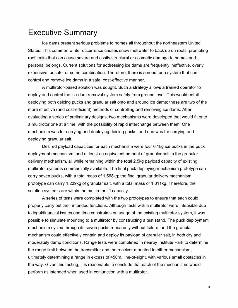
Ice dams present serious problems to homes all throughout the northeastern United
States. This common winter occurrence causes snow meltwater to back up on roofs, promoting
roof leaks that can cause severe and costly structural or cosmetic damage to homes and
personal belongs. Current solutions for addressing ice dams are frequently ineffective, overly
expensive, unsafe, or some combination. Therefore, there is a need for a system that can
control and remove ice dams in a safe, cost-effective manner.
A multirotor-based solution was sought. Such a strategy allows a trained operator to
deploy and control the ice-dam removal system safely from ground level. This would entail
deploying both deicing pucks and granular salt onto and around ice dams; these are two of the
more effective (and cost-efficient) methods of controlling and removing ice dams. After
evaluating a series of preliminary designs, two mechanisms were developed that would fit onto
a multirotor one at a time, with the possibility of rapid interchange between them. One
mechanism was for carrying and deploying deicing pucks, and one was for carrying and
deploying granular salt.
Desired payload capacities for each mechanism were four 0.1kg ice pucks in the puck
deployment mechanism, and at least an equivalent amount of granular salt in the granular
delivery mechanism, all while remaining within the total 2.5kg payload capacity of existing
multirotor systems commercially available. The final puck deploying mechanism prototype can
carry seven pucks, with a total mass of 1.568kg; the final granular delivery mechanism
prototype can carry 1.239kg of granular salt, with a total mass of 1.811kg. Therefore, the
solution systems are within the multirotor lift capacity.
A series of tests were completed with the two prototypes to ensure that each could
properly carry out their intended functions. Although tests with a multirotor were infeasible due
to legal/financial issues and time constraints on usage of the existing multirotor system, it was
possible to simulate mounting to a multirotor by constructing a test stand. The puck deployment
mechanism cycled through its seven pucks repeatedly without failure, and the granular
mechanism could effectively contain and deploy its payload of granular salt, in both dry and
moderately damp conditions. Range tests were completed in nearby Institute Park to determine
the range limit between the transmitter and the receiver mounted to either mechanism,
ultimately determining a range in excess of 450m, line-of-sight, with various small obstacles in
the way. Given this testing, it is reasonable to conclude that each of the mechanisms would
perform as intended when used in conjunction with a multirotor.
xi
Terminology
UAV - Unmanned Aerial Vehicle. A vehicle that is meant to be re-used and has no pilot on
board, is controlled via radio, and can carry payloads [1]. May also be autonomous.
UAS - Unmanned Aircraft System. Essentially identical to the term “UAV.” The word “system”
refers to the fact that besides the aerial vehicle itself, ground stations or other components may
also be present. Term adopted by the FAA [2].
Drone - General term for UAVs or UASs.
FAA - Federal Aviation Administration. United States government agency that regulates the use
of private and commercial aerial systems.
Propeller (Prop) - A revolving shaft with two or more airfoils attached that generates thrust.
Typically oriented with the shaft along the direction of travel, as in a conventional prop-driven
plane [3].
Rotor - A revolving shaft with two or more airfoils attached that generates thrust. Typically
oriented with the shaft along the line of increasing altitude above Earth’s surface, as in a
helicopter [61]. Often used interchangeably with the terms “propeller” or “prop.”
Helicopter - Aerial vehicle consisting of two rotors, one of which provides lift and direction
control, and the other which counters the rotation produced.
Multirotor - General term that refers to any aerial vehicle with more than two rotors.
Quadcopter (Quadrotor) - Aerial vehicle that consists of four rotors.
Hexacopter (Hexarotor) - Aerial vehicle that consists of six rotors.
Octocopter (Octorotor) - Aerial vehicle that consists of eight rotors.
Gimbal - Stabilization device that keeps an object at a fixed orientation. When applied to
multirotors, gimbals often take the form of vibration-reducing, camera-pointing mechanisms.

xii
FPV - First Person View. In the world of multirotors, refers to the paired setup of camera and
goggles that allow the operator to see a live camera feed, essentially providing the operator with
the view that the multirotor has.
1
1.0 Introduction
Heavy snowfall plagues states across the Northern United States every year. States in
the Northeast are generally hit particularly hard with snow. Worcester, MA alone received a total
snowfall of 119.7 inches, or 10 feet, in the 2014-15 season. This made Worcester the second
snowiest location in the United States for the season, coming behind Lowell, MA by less than an
inch [4].
Removing snow from winter roads is only part of the battle. In addition to accumulating
on roads, snow also accumulates on the roofs of houses, businesses, and a variety of other
structures. When neglected, this accumulated snow is often prone to melting and refreezing
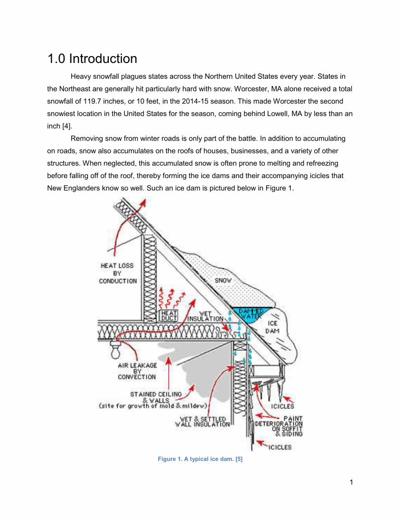
before falling off of the roof, thereby forming the ice dams and their accompanying icicles that
New Englanders know so well. Such an ice dam is pictured below in Figure 1.
Figure 1. A typical ice dam. [5]
2
Ice dams are accumulations of ice on roof edges that dam newly-melted snow from
further up the roof, preventing it from draining properly. The weight of these ice dams and the
dangerous falling-icicle hazards that they promote can pose threats of physical harm to people
and animals. These ice dams also pose an array of pernicious financial effects. When meltwater
is hindered from draining off the roof, it finds the path of least resistance, and being pushed
downward by gravity, leaks through damaged or imperfect sections of roof and into the
underlying structure. The resulting water damage to insulation, wood framing, drywall, and
various other components, can cost thousands of dollars to rectify, not including the damage
done to personal property.
Means of addressing ice dams and the corresponding meltwater already exist in the
form of various preventative, control, and removal measures. The focus of the project is on
addressing ice dams that already do exist, and when it comes to control or removal measures,
there are few viable options. One option is to purchase deicing pucks, which essentially operate
by melting channels in the ice dam through which the trapped meltwater can then drain. At
present, this method’s effectiveness is determined by one’s throwing arm and aim, or by the
height of the ladder used to more precisely position the pucks, often making this method
inaccurate and/or dangerous to the operator. The alternatives are to spend hundreds or
thousands of dollars to have a professional service remove the ice, or to risk life, limb, and roof
by doing it oneself. And once the next Nor’easter passes through, those ice dams will soon be
back in full force and in need of removal once again.
An unlikely technology that is currently gaining worldwide prominence may help to solve
the problems and expenses associated with ice dam control and removal. Unmanned Aerial
Vehicles (UAVs), also referred to as Unmanned Aircraft Systems (UASs) are most prominently
featured in the public eye as war machines that deliver drone strikes. Commercially in the
United States, small UASs also make popular remote-controlled toys. These usually take the
form of small helicopters, quadrotors, or more generally as multirotors (with any number of
props). Businesses and organizations use slightly bigger UASs with great success. Tune in to
an NFL game, and you will likely see a UAS with a camera attached flying over the field and
delivering close video coverage of the game.
Granted, the main purpose and attraction of these UASs has frequently been to carry
smaller built-in cameras for taking pictures and video. However, in relevance to this project, a
promising fact about UASs is that, provided a large and powerful enough UAS, the aircraft can
carry payloads of varying sizes. Many sport gimbal mounts allow for the mounting of larger
cameras and other equipment to UASs, which control the orientation and stabilization of the

3
mounted equipment. Hobbyists all over the world have tailored multirotors to carry non-camera
payloads and perform various tasks, using gimbal mounts and/or custom-made apparatuses.
As the popularity of multirotors has increased over the past few years, commercial use
and liability issues have become thorny subjects in the United States, and various regulations
are already being passed here and in other countries. The use of multirotors will only increase
as time passes, with new practical uses being discovered and regulations being fine-tuned and
more manageable to work with.
Given the increasing practical capabilities of multirotors, and the unrelenting issues
posed by ice dams, this project aims to design and construct a payload for a multirotor that will
address the aforementioned problems associated with ice dams. The specific purposes of the
payload shall be to first promote and improve the ability of meltwater to drain from behind the
dams, and secondly, to gradually melt the ice dam as a whole. These efforts are part of a two-
step process to clear winter roofs, using a conventional “roof rake” to remove the snow, and this
“aerial roof rake” system to remove the ice dam once it has already formed.
A standard design process was implemented by the project. This process is briefly
outlined below.
● Identify Need
● Background Research
● Goal Statement
● Task Specifications
● Ideation/Invention
● Modeling and Analysis
● Solution Selection
● Detailed Design
● Prototype
● Test

4
2.0 Identification of Need
This project aims to enable the draining of meltwater trapped behind roof-top ice dams,
and to gradually eliminate ice dams in their entirety.
5
3.0 Background Research
3.1 Ice Dams and Their Effects
For centuries, ice dams have presented problems to homes and homeowners,
predominantly in areas where frequent seasonal snowfall and below-freezing temperatures
occur. Although the ice formations themselves usually do not directly compromise homes, the
melted snow (meltwater) that builds up behind them can. When prevented from draining, this
meltwater leaks through roofs, causing water damage. This damage requires costly repairs and
often recurs when measures are not taken to abate and prevent the ice dams. Ice dams and
their icicles may look pretty, but they demand serious attention from homeowners.
Refer back to Figure 1 in Section 1 for an illustration of a typical ice dam. Ice dams form
when the upper portions of a roof have above-freezing surface temperatures, and the lower
portions have below-freezing surface temperatures. Given a poorly insulated and air-sealed
roof, and several days of subfreezing ambient temperatures, only one or two inches of
accumulated snow are needed for ice dams to form [6]. The root cause of ice dam formation is
heat that escapes from the interior of the home, conducting through drywall, wood, and ceiling
insulation, before reaching the attic where it then convects toward the roof. If the roof is poorly
insulated, this heat conducts through it to the outside air.
When this heat transfer raises the roof’s surface temperature above 32o F, snow that is
lying on these portions of the roof melts and flows toward the eaves. These eaves are typically a
foot away from the house, and therefore do not receive significant amounts of stray heat from
the attic and heat duct areas. Therefore, the roof edges generally remain below 32o F, causing
the meltwater to refreeze when it reaches these portions of the roof. Over time, meltwater
originating from heated portions of the roof continues to run onto and refreeze on the eaves,
thereby forming ice dams.
As the ice dam grows, it eventually covers the entire eave. At this point, the remaining
portions of the roof are the heated portions from which meltwater is originating; this meltwater
begins to collect behind the dam, and the heat conducting through the roof from the attic and
heat duct areas keeps this meltwater water from re-freezing. Since the ice dam prohibits water
from dripping off the edge of the roof, the meltwater inevitably finds the path of least resistance
and begins leaking through the roof, ultimately coming in contact with interior wood, insulation,
drywall, and personal items. This leakage causes wood rot, damage to insulation and drywall,
and mold and mildew growth [5].
6
As insulation becomes soaked with meltwater, it thins or compresses, resulting in lower
effective R-values and a diminished capacity to retain heat. Conversely, as snow continues to
accumulate on the roof, it serves as insulation and its capacity to retain heat increases, causing
heat directly beneath the snowy roof to become trapped. With diminished insulation between the
house interior and attic, and increased insulation between the attic and roof exterior, more heat
builds up in the attic, thereby promoting further meltwater formation, and ultimately, greater
resulting home damages [6].
3.2 Ice Dam Prevention, Control, and Removal
In order to temporarily halt or even prevent meltwater leaks and the severe resulting
damages that they are capable of causing, homeowners can take a variety of different
measures, ranging from preventing ice dam formation in the first place, to controlling and/or all-
out removing ice dams. For the sake of clarity in the following section of the report, these
measures are divided into three categories: 1) Ice Dam Prevention, 2) Ice Dam Control, and 3)
Ice Dam Removal.
3.2.1 Ice Dam Prevention
This first category presents measures taken by homeowners to prevent ice dam
formation, or at least largely diminish their potential impact, well before snow and ice hit (with
the exception of the last method). Research yielded six common measures taken to prevent the
formation of ice dams.
Ensuring Adequate Attic Insulation
Adequate attic insulation is essential to keeping heat in the living areas of the house, out
of the attic, and consequently, away from the roof. To ensure that the insulation used is
sufficient for preventing heat loss, homes in the northern United States should have ceiling
insulation with an R-value of 38 (R-38) or greater. Additionally, this ceiling insulation should be
continuous and consistently deep about the entire ceiling area [6]. The less heat that escapes
from the house and into the roof, the less likely that different portions of the roof will be above
and below freezing, and the less likely that ice dams will form. In addition to preventing ice dam
formation, adequate insulation can help homeowners to save significantly on home heating
costs [7].
7
Ensuring Optimal Roof Ventilation
In some cases, including cases where seemingly adequate insulation has been installed,
heat still escapes from the house and into the attic. To diminish the amount of heat that builds
up in attics and ultimately promotes meltwater leaks, proper roof ventilation should be ensured.
An adequately-designed roof ventilation system allows air to move through the attic and rafter
spaces, preventing warm air from building up in the attic. To ensure an effective ventilation
system, the total free intake area venting to the attic must be greater than or equal to the total
free exhaust area venting from the attic. Additionally, half of the venting area should be placed
high in the attic (for exhaust), and the other half should be placed low in the attic (for intake).
This placement allows for a continuous flow of air that moves from the bottom to the top of the
attic [8].
Sealing and Insulating All Ceiling Penetrations
Common household fixtures such as bathroom fans, plumbing vents, and recessed
ceiling lighting can allow large amounts of warm air to escape from living areas and into the attic
when improperly sealed. By taking time to properly seal these fixtures, the amount of warm air
escaping to the attic will be reduced, thereby lowering the risk of ice dam formation. On this
note, recessed lighting, also known as lighting cans, should be used sparingly, or avoided if
possible. Lighting cans generate an excessive amount of heat, and when improperly sealed,
can release significant heat directly into the attic, ultimately promoting meltwater and ice dam
formation.
8
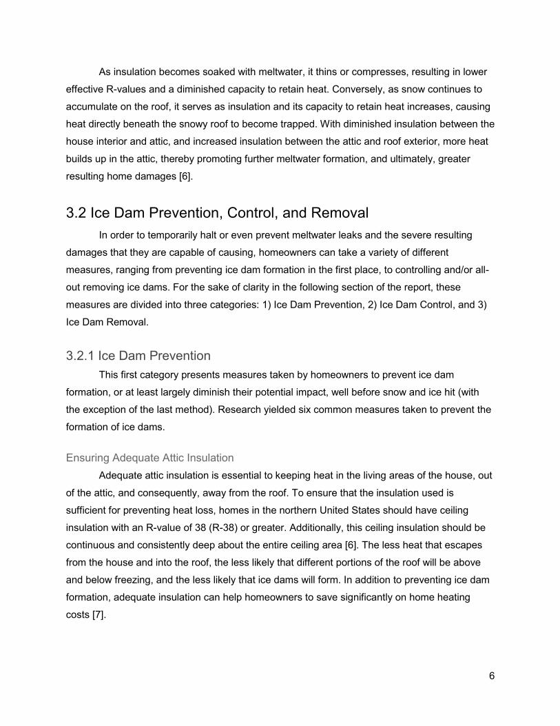
Installing Heat Tape and Heat Cables
Figure 2. Heat cables installed along the edge of a roof. [9]
The installation of heat tape or heat cables along the lower portions of the roof (along the
edge) can help to reduce ice dam formation. A typical installation is shown in Figure 2. It should
be noted that when such cables are improperly installed and/or used, they can present fire
hazards and create a backflow of meltwater that worsens roof leaks. Additionally, heat cables
are essentially useless if the structure on which they are installed has severe insulation and
ventilation problems. When these insulation and ventilation problems exist, it is likely that
meltwater leaks will occur well above the edge of the roof, or in the area where the heat tape
itself lies, where ice dams would otherwise form [7].
Maintaining Clean Gutters
Contrary to common belief, gutters do not directly cause ice dams. In fact, they can help
to prevent ice dams when properly maintained. The function of gutters is to collect water from
the roof and channel it to the ground. When filled with leaves, twigs, and other forms of clutter,
gutters cannot effectively channel meltwater that does reach them. Thus, in the winter, any
meltwater that does reach a clogged gutter will not be able effectively channel off of the roof and
will be prone to freezing in the gutter. Once gutters are completely clogged with clutter and
frozen water, they can no longer drain water and ice dam formation is thereby propagated [6].
9
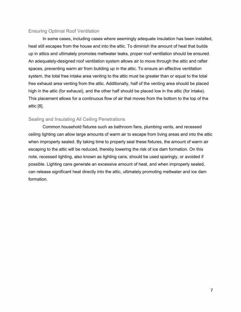
Removing Snow from the Roof
Figure 3. A roof rake device. [10]
Recall from earlier that ice dams and the meltwater that collects behind them are the
result of roof-top snow being heated, and thereby melted. With this being said, if there is no
snow on the roof, there can be no meltwater. Therefore, homeowners or snow removal services
can use roof rakes and shovels to remove snow from roof tops. Roof rakes are typically safer
and more effective, as they can be operated from ground level and are designed specifically for
the task of roof-top snow removal. These devices are simple, typically comprised of a long pole
attached to a horizontal sheet, as pictures in Figure 3. Pushing the device’s head under the
snow and advancing up the roof, the snow gets forced over the sheet, and subsequently slides
down it and off the roof.
If snow is removed before an ice dam forms, then the ice dam and meltwater will be
avoided altogether. Even if an ice dam has already formed, when snow is removed, the problem
of further meltwater generation will be eliminated and only the dam will remain. Either way,
using a roof rake to remove snow from a roof is an effective way of preventing ice dams and the
meltwater that first causes, and then gathers behind them.
10
3.2.2 Ice Dam Mitigation
In many cases, even the best preventative measures cannot guarantee total ice dam
prevention, and in many cases, homeowners do not have the time, money, and/or desire to take
preventative measures in the first place. When ice dams do form, they must first be controlled,
and all-out removed if possible or deemed necessary. Controlling an ice dam entails enabling
the built-up meltwater to drain from behind the dam, in order to keep it from leaking into the
house. Common and effective measures for draining meltwater are described here.
Placing Deicing Pucks
This method entails placing deicing pucks both behind and on top of the ice dam.
Deicing pucks are small, cylindrical units of compacted salt, that salt most commonly being
calcium chloride (CaCl2). Pucks are typically two or three inches in diameter and one inch in
height, and are available in prepackaged quantities at local hardware and home improvement
stores. A common brand found either online or in the Worcester area is Roofmelt Ice Melt
pucks, which is available in 60-puck containers at Home Depot and Lowe’s [11].
The puck product is intended to be tossed onto a roof, ideally landing directly behind the
ice dam. Composed of calcium chloride, these pucks react exothermically with water, helping to
melt the ice it lands on. This ultimately allows the puck to sink down to the roof, where it comes
in contact with dammed meltwater. The puck mixes with the meltwater, forming a brine solution
that comes directly in contact with the wall of the ice dam. This brine solution has a lower
freezing point than the ice in front of it, preventing it from freezing as well. Coupled with the
exothermic reaction that calcium chloride undergoes in contact with water, the mixture increases
the rate at which the ice dam melts, ultimately eliminating the dam and allowing the meltwater to
drain off of the roof [12]. The more pucks thrown behind the dam and the more area covered,
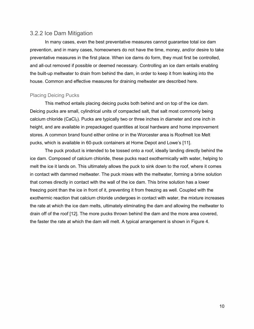
the faster the rate at which the dam will melt. A typical arrangement is shown in Figure 4.
11
Figure 4. Ice melt pucks placed along an ice dam. [13]
The method previously described, while increasing the melting rate of the ice dam as a
whole, does not address the immediate need of allowing meltwater to drain from behind the
dam. In order to sufficiently drain meltwater and stop roof leaks, channels must be formed in the
ice dam. To achieve this, a ladder must typically be used to manually place pucks on top of the
dam. Pucks should be placed collinearly, parallel to the slope of the roof, spaced approximately
two to three inches apart, and in quantity to cover the entire width of the ice dam (the dimension
parallel to the slope of the roof). These individual lines of pucks should be spaced approximately
four to five inches apart along the entire length of the ice dam.
As each of the pucks melt the ice below and around them, they sink through the dam
and ultimately reach the roof. Upon reaching the roof, gravity causes the pucks to begin
progressing downward along the slope of the roof, melting the ice in front of them and ultimately
reaching the edge of the roof. As the pucks reach the edge of the roof, channels through the ice
have been formed behind them; collected meltwater can then flow through these channels,
thereby draining from behind the dam and stopping leaks into the house [13].
At present, both of the methods described above require the user to either toss the
pucks onto the roof from ground level, or to access the roof via ladder or other means to
manually place the salt pucks. Tossing pucks onto the roof does not guarantee accurate or
optimal placement, and manually placing pucks on a roof presents substantial falling hazards
that can lead to serious injury or death [14]. Given the effectiveness of these methods, a means
to exercise them in a safer, more effective way would be ideal.
12
It should be noted that calcium chloride can pose some health threats to both vegetation
and pets alike. While less toxic to plants than sodium chloride (also known as rock salt), calcium
chloride can be extremely harmful to pets if contacted or consumed in large quantities [15][16].
Calcium chloride is a common salt puck composition, so the owners of pets should exercise
caution.
Placing Permeable Deicing Units (AKA Trough-makers)
This method works similar to the deicing puck method in that it involves creating
channels through which meltwater can flow. This method involves placing a permeable filter,
containing a salt core (either calcium chloride or magnesium chloride) in the meltwater on top of
the ice dam. Unlike deicing pucks, these filters are not commercially available, but can be made
easily by filling a pantyhose with granular salt. The pantyhose serves as the permeable layer.
When placed on top of the dam, the filter functions much like a deicing puck, releasing
heat on contact with the ice and melting it, thereby creating meltwater that penetrates through
the permeable layer and into the salt core. This creates a brine solution with a lower melting
temperature than the ice, remaining as a liquid and helping to melt the ice dam. As the filter
sinks into the ice dam, a channel forms and gradually increases in depth until the filter reaches
the roof. These channels allow meltwater to drain from behind the dam. To improve
effectiveness, multiple filters, spaced four to five inches apart, should be placed parallel to the
slope of the roof over the entire width of the ice dam. In order to accelerate the formation of a
brine solution, water should be poured over the filters after they are placed over the ice dam.
In an experiment conducted by a home inspector, one week after placement of several
trough-makers, none of them had made even a dent in the ice dam. This was likely due to the
fact that the temperatures were near-zero for the entire week, making it difficult for the salt to
sufficiently release the requisite heat to melt the ice and form a brine. Therefore, while this may
be an effective method in theory, it is potentially very temperature-sensitive and overall not
nearly as effective as deicing pucks [13].
13
3.2.3 Ice Dam Removal
After first controlling ice dams (providing a means for the collected meltwater to drain),
many homeowners wish to completely eliminate ice dams. A variety of measures can be
employed to achieve this. Most commonly, these measures include steam blasting and manual
removal. Granular deicing agent may also be used (as it is used widely on roads and
sidewalks), but this results in a much slower melting process.
Removal by Steam Blasting
Commercially, steam blasting is the most common method for removing ice dams. This
method involves using a steam blaster to spray steam onto the ice dam. As pressurized steam
lands on the ice dam, it quickly melts the ice, ultimately eliminating the entire dam in a matter of
hours, depending on the size of the dam [17]. When maintained and used properly, steam
blasters can generally remove 10 to 15 feet of ice dam per hour [18]. This method does not
structurally compromise the roof, whereas manual removal by hammer and ice pick can cause
significant roof damage [19]. Many companies offer steam blasting service but it can be very
expensive; some estimates range between $425 and $825 per hour [20]. Two customers in
Massachusetts report paying $475/hr [21]. Prices are typically determined on a case-by-case
basis. Several steam-blaster ice dam removal services cater to the Worcester area, including
Lavallee Home and Property Services, Perfect Power Wash LLC, and Quality Cleaning and
Restoration [22][23][24].
Manual Removal
In contrast to the steam blasting method, this method entails using hammers, ice picks,
shovels, and other manually operated tools to remove ice dams. This method is more prone to
causing roof damage (particularly to shingles) and is the most dangerous and time-consuming
method for removing an ice dam [19]. Given the dangers associated with this method,
homeowners are encouraged to hire professionals to remove ice dams in this manner. One ice
dam removal service in the Worcester MA area that performs manual removal is Nor’easter
Roofing Inc. [25].
14
Removal by Continuous Deicing Agent Application
Another possible method for removing an ice dam is to continuously coat the ice dam,
both on top of and behind the dam, with a granular deicing agent. Similar to deicing pucks, this
deicing agent melts the ice and forms brine with a decreased melting temperature from the ice
that it contacts. Whereas deicing pucks are more effective at forming channels for meltwater to
drain through, granular deicing agent can be more easily spread over large areas, quickly
covering more dam surface area and promoting ice melting over the entire structure. In order to
ensure continual melting of the dam, several coats of granular deicing agent may need to be
applied over time.
Given that granular deicing agents are more easily spread, they are more prone to
contaminating large areas than deicing pucks. Additionally, whereas deicing pucks are designed
for use on roof surfaces, many granular agents are designed for use on steps and walkways.
Therefore, it is important to ensure that the granular agent used is safe for pets, vegetation, and
building materials. Granular deicing agents labeled as “pet-safe” should be used, as they do not
harm pets or vegetation, and do not compromise common building materials. These pet-safe
agents are most commonly composed of a substance known as Urea (also known as Carbonyl
Diamide or Carbamide Resin) [26] or Magnesium Chloride. Pet-safe granular deicing agents are
available for order online or at local hardware stores.
Despite its potential for effectiveness, this is the slowest method for directly removing an
ice dam. Whereas the previous two removal methods can be completed between several hours
and a day’s worth of time, and will immediately relieve any dammed meltwater, this method will
take significantly longer and will not immediately relieve meltwater. Therefore, when this method
is exercised, channels should first be formed in the dam via deicing pucks or trough-makers.
This ensures that meltwater is drained from the dam as quickly as possible, thereby eliminating
roof leaks. It is important to remember that rather than the ice dam itself, the dammed meltwater
and corresponding roof leaks present the largest threats to the roof and underlying structure.
15
3.3 Multirotors
Ice dams may be prevented, mitigated, or outright removed via a host of time-consuming
or expensive measures. Once an ice dam has already formed, mitigation is the primary goal.
Mitigation is the least-developed option of the three, relying on salt to form troughs. The only
alternative (once a dam has already formed) is removal, which puts one at risk of falling off
ladders or damaging the roof, or requires paying others to professionally remove them.
As a more rapid, safe, and cost-efficient way of ferrying de-icing salt to the roof,
multirotors were explored as a deployment vehicle. Multirotors are a type of UAV (or “drone”),
most commonly operated using a transmitter within line-of-sight. The use of a multirotor allows
operation from ground level, with no risk of slipping off of a roof or being hit by falling ice. An
emphasis on the process being fast and cheap could allow a business to be formed around this
strategy.
While choosing an adequate multirotor platform, emphasis was placed on ease of use,
flight readiness (out of the box), payload capacity, and number/type of potential payload
mounting points. The presence and location of landing gear, as well as prop guards to prevent
damage when flying close to a roof, were also taken into consideration.
Preliminary research into multirotors showed that “heavy payload” usually only entails
about 1kg of payload. Most readily-available multirotors are not made to handle high payloads.
In theory, the selection and assembly of individual components allows for higher payloads (as
demonstrated by HobbyKing’s annual Beer Lift competition [27]).
Efforts were directed at the development of a multirotor payload and not at the
development of a multirotor itself, so this method was not considered. For purposes of
redundancy and cost effectiveness, it was decided to design for the multirotor that another MQP
team on campus had previously obtained. The decision-making process before this conclusion
was reached is shown in Sections 3.3.1 through 3.3.4.
16
3.3.1 DJI Phantom 3
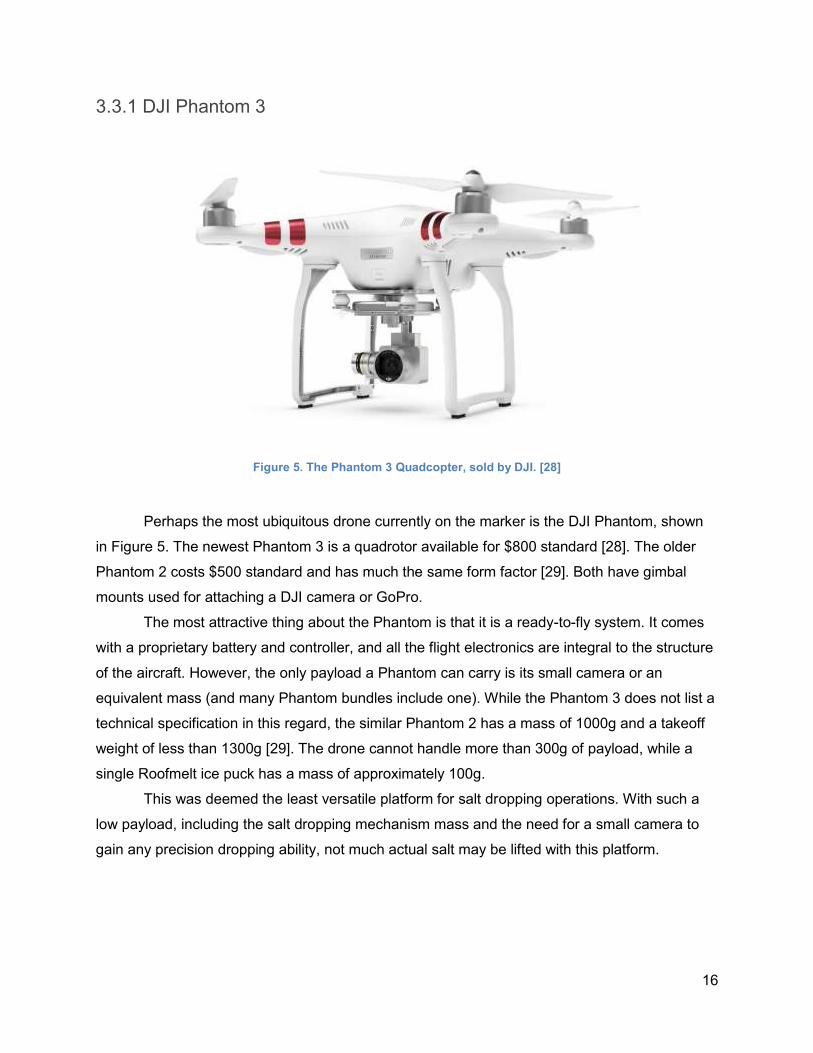
Figure 5. The Phantom 3 Quadcopter, sold by DJI. [28]
Perhaps the most ubiquitous drone currently on the marker is the DJI Phantom, shown
in Figure 5. The newest Phantom 3 is a quadrotor available for $800 standard [28]. The older
Phantom 2 costs $500 standard and has much the same form factor [29]. Both have gimbal
mounts used for attaching a DJI camera or GoPro.
The most attractive thing about the Phantom is that it is a ready-to-fly system. It comes
with a proprietary battery and controller, and all the flight electronics are integral to the structure
of the aircraft. However, the only payload a Phantom can carry is its small camera or an
equivalent mass (and many Phantom bundles include one). While the Phantom 3 does not list a
technical specification in this regard, the similar Phantom 2 has a mass of 1000g and a takeoff
weight of less than 1300g [29]. The drone cannot handle more than 300g of payload, while a
single Roofmelt ice puck has a mass of approximately 100g.
This was deemed the least versatile platform for salt dropping operations. With such a
low payload, including the salt dropping mechanism mass and the need for a small camera to
gain any precision dropping ability, not much actual salt may be lifted with this platform.
17
3.3.2 3D Robotics X8+
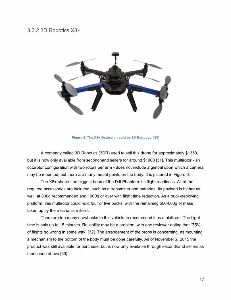
Figure 6. The X8+ Octorotor, sold by 3D Robotics. [30]
A company called 3D Robotics (3DR) used to sell this drone for approximately $1350,
but it is now only available from secondhand sellers for around $1000 [31]. This multirotor - an
octorotor configuration with two rotors per arm - does not include a gimbal upon which a camera
may be mounted, but there are many mount points on the body. It is pictured in Figure 6.
The X8+ shares the biggest boon of the DJI Phantom: Its flight readiness. All of the
required accessories are included, such as a transmitter and batteries. Its payload is higher as
well, at 800g recommended and 1000g or over with flight time reduction. As a puck-deploying
platform, this multirotor could hold four or five pucks, with the remaining 500-600g of mass
taken up by the mechanism itself.
There are too many drawbacks to this vehicle to recommend it as a platform. The flight
time is only up to 15 minutes. Reliability may be a problem, with one reviewer noting that “75%
of flights go wrong in some way” [32]. The arrangement of the props is concerning, as mounting
a mechanism to the bottom of the body must be done carefully. As of November 2, 2015 the
product was still available for purchase, but is now only available through secondhand sellers as
mentioned above [33].
18
3.3.3 DJI S900
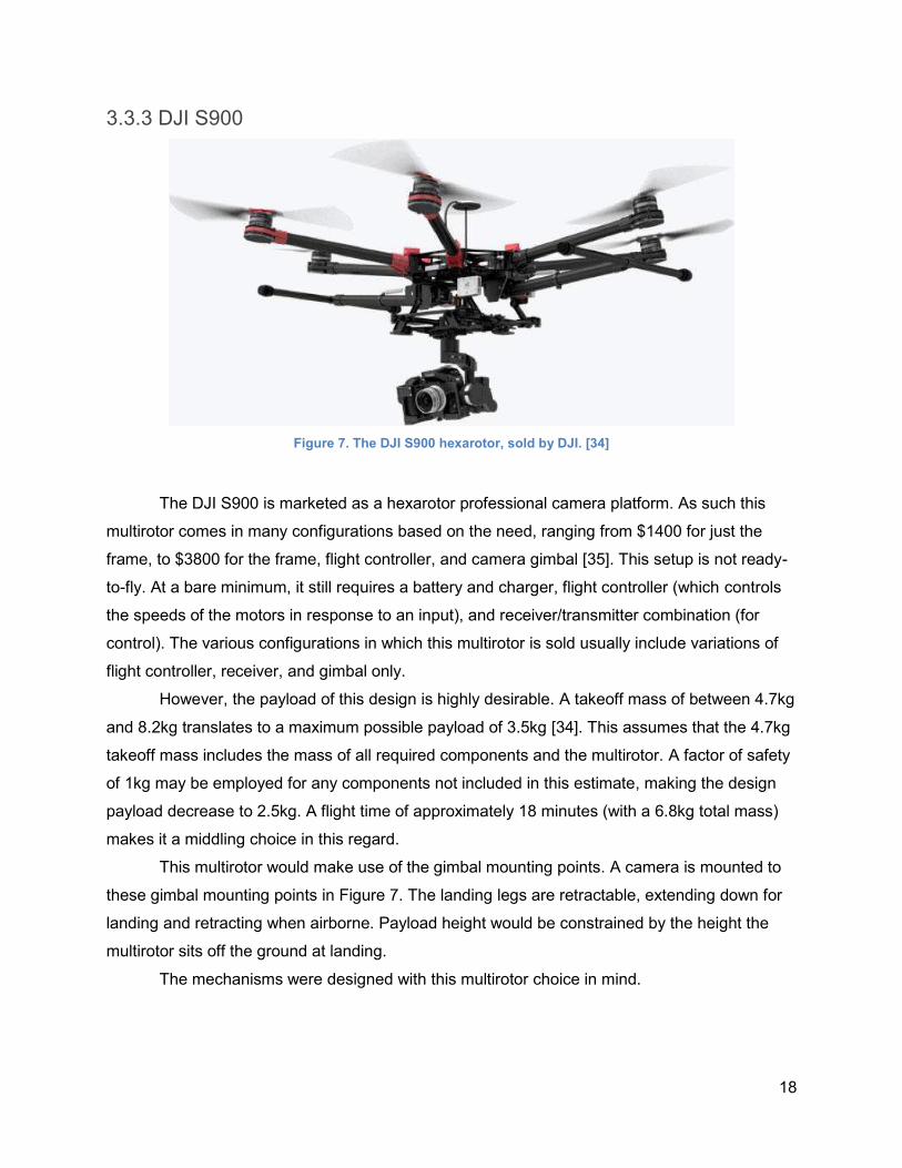
Figure 7. The DJI S900 hexarotor, sold by DJI. [34]
The DJI S900 is marketed as a hexarotor professional camera platform. As such this
multirotor comes in many configurations based on the need, ranging from $1400 for just the
frame, to $3800 for the frame, flight controller, and camera gimbal [35]. This setup is not ready-
to-fly. At a bare minimum, it still requires a battery and charger, flight controller (which controls
the speeds of the motors in response to an input), and receiver/transmitter combination (for
control). The various configurations in which this multirotor is sold usually include variations of
flight controller, receiver, and gimbal only.
However, the payload of this design is highly desirable. A takeoff mass of between 4.7kg
and 8.2kg translates to a maximum possible payload of 3.5kg [34]. This assumes that the 4.7kg
takeoff mass includes the mass of all required components and the multirotor. A factor of safety
of 1kg may be employed for any components not included in this estimate, making the design
payload decrease to 2.5kg. A flight time of approximately 18 minutes (with a 6.8kg total mass)
makes it a middling choice in this regard.
This multirotor would make use of the gimbal mounting points. A camera is mounted to
these gimbal mounting points in Figure 7. The landing legs are retractable, extending down for
landing and retracting when airborne. Payload height would be constrained by the height the
multirotor sits off the ground at landing.
The mechanisms were designed with this multirotor choice in mind.
19
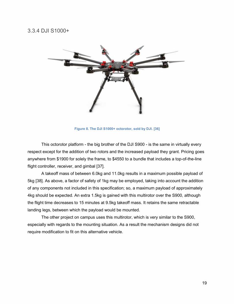
3.3.4 DJI S1000+
Figure 8. The DJI S1000+ octorotor, sold by DJI. [36]
This octorotor platform - the big brother of the DJI S900 - is the same in virtually every
respect except for the addition of two rotors and the increased payload they grant. Pricing goes
anywhere from $1900 for solely the frame, to $4550 to a bundle that includes a top-of-the-line
flight controller, receiver, and gimbal [37].
A takeoff mass of between 6.0kg and 11.0kg results in a maximum possible payload of
5kg [38]. As above, a factor of safety of 1kg may be employed, taking into account the addition
of any components not included in this specification; so, a maximum payload of approximately
4kg should be expected. An extra 1.5kg is gained with this multirotor over the S900, although
the flight time decreases to 15 minutes at 9.5kg takeoff mass. It retains the same retractable
landing legs, between which the payload would be mounted.
The other project on campus uses this multirotor, which is very similar to the S900,
especially with regards to the mounting situation. As a result the mechanism designs did not
require modification to fit on this alternative vehicle.
20
3.3.5 Feasibility of Select Multirotor Modifications
While researching multirotors, a few modifications extending the abilities of the system
were proposed. Their feasibilities are discussed briefly here.
Powered Tether
The S900 has six 40A ESCs (Electronic Speed Controllers) that interface with the six
motors. At absolute full power, the current load is therefore 240A. The multirotor’s
recommended 6S LiPo battery (six-celled lithium-polymer battery, at 3.7V per cell) will output
22.2V. A powered tether would have to output 22.2V 240A power, with the capability to rapidly
fluctuate as the demands of the motors change. Use of the S1000+ would only increase this
demand.
Most power supplies cannot handle this (interview with Joseph St. Germain, 02 Nov
2015, Appendix B). In order to make this feasible, the power supply should instead power a
ground-based battery which provides the flow of current through the tether. Larger current
results in a larger diameter wire required. For this application, a 000 or 3/0 AWG (American
Wire Gauge) wire would be required, with a diameter of 0.41in [39]. The weight of such a wire
would be prohibitive to the payload capacity of the multirotor, which can fly for a solid 15
minutes untethered (using the recommended 6S 15000mAh LiPo battery) anyways.
Prop Guards
Adding prop guards adds weight to the design. The S900 has six rotors to protect, while
the S1000+ adds two more. Changing or loading of mechanisms will be done with the quadrotor
fully powered off. We do not expect much time on the ground, given that the action of reloading
requires either sliding out the mechanism and loading four pucks (puck mechanism), or sliding
out the mechanism and pouring in salt (granular mechanism). So, such guards may be
unnecessary.
However, a minimalistic guard (like a stiff wire surrounding the vehicle) may add minimal
weight and still prevent a close call, should one occur. This option was not developed due to the
project’s lack of multirotor availability.
21
3.3.6 Legality of Multirotor Use
The legality of multirotor use in the US changes between recreational, commercial, and
public use. Public use requires a Certificate of Waiver or Authorization (COA), and may only be
granted to public entities such as publically-funded universities (while WPI is privately funded).
However, a COA may be required for private operations as well [40]. As it is unlikely that use at
WPI constitutes either of these, the remaining two categories will be discussed.
MQPs constitute multirotor use for education. It is unclear whether this falls under private
or recreational use, so a COA may be necessary. If it is simply recreational use, there are safety
guidelines that must be followed in the operation of the multirotor. For example, a maximum
altitude of 400ft is allowed, flight within 2 nautical miles of a heliport is disallowed, and flight
within 5mi of an airport must be approved by the local control tower [41]. As of 21 Dec 2015, the
FAA also requires the registration of any “model aircraft” between 0.55lb and 55lb. Above 55lb
is not allowed [42] unless the aircraft is certified by a community-based organization [43].
Commercial use refers to the use of a UAS for any business purpose - professional,
contract, or for compensation in general [44]. The regulations regarding use here are rather
vague; to be safe, a Section 333 exemption should be filed. These are granted on a case-by-
case basis by the FAA and allow commercial use [45], but take some time to process.
The regulations in the US for multirotor use are not very clearly defined, and are in fact
rather restrictive for anyone not using their multirotor as simply a toy. Most people by now know
of the excitement that Amazon Prime Air multirotor package delivery has caused, yet Amazon is
still subject to the restrictive and vague regulations by the FAA. The industry is being hamstrung
by the current state of the law.
Around the world, multirotor use is increasing in response to more clearly defined or un-
restrictive regulations, and the promise that UAVs hold as a technology. For example, Special
Flight Operations Certificates (SFOCs) were required to operate multirotors in Canada (similar
to Section 333 exemptions in the US), until a 27 Nov 2014 law granted blanket exemptions for
“...’very small’ 2kg (4 lb., 6.55 oz.) UAVs and ‘small’ 2 to 25kg (55 lb., 1.8oz.) UAVs that would
eliminate the need for an SFOC if certain conditions are met” [46]. Regulations are not as
advanced in Russia, and yet experiments such as a company using drones to fly banners for a
restaurant at lunch time have met great success. Similarly, a company in Brazil took advantage
of the technology in the holiday season of 2014, advertising its clothing with flying mannequins
wearing it [46].
It is clear that if a business plan were to be pursued as a result of the project, a Section
333 exemption would be required. Solely education-related use is less clear. Ultimately, the
22
issue may be one of liability. An individual (e.g. a faculty member) could purchase and register a
UAS for their personal recreational use and “allow” students to use it; or the university could buy
it, in which case a Section 333 exemption and/or a COA may be required. Either way, the
purchasing party is the one liable for any damages that result from the use of the multirotor.
23
4.0 Goal Statement
The goal of this project is to develop a multirotor-mounted system which drops Roofmelt
salt pucks and granular pet-safe ice melt.
5.0 Task Specifications
1. The system carries both standard Roofmelt Ice Melter Tablets (i.e. deicing pucks) [11]
and pet-safe granular ice melt [47]
2. The system carries a minimum of 4 deicing pucks per-run
3. The system carries a minimum quantity of granular salt equivalent to the mass of 4
deicing pucks
4. All components of the system are be corrosion-resistant to water, Calcium Chloride,
Magnesium Chloride, and Urea
5. If the system is composed of multiple mechanisms, they must be rapidly interchangeable
6. The system is manually-controlled from a ground controller
7. The system uses line-of-sight operation
8. When mounted on the multirotor, the system (one mechanism and its corresponding full
load of salt) does not exceed a mass of 2.5kg
9. The center of mass of a mounted mechanism remains within 0.5in of the center of mass
of the multirotor, to the left or right of the forward-pointing pitch axis
10. The system is powered and controlled independently of the multirotor
11. The Transmitter/Receiver combination avoids the 5.8GHz frequency, to avoid
interference with the multirotor’s pre-existing control system
12. The Transmitter/Receiver combination has at least two programmable channels
13. Each mechanism comprising the system uses a maximum of two actuators
14. The system mounts to the multirotor using the multirotor’s gimbal mounts
15. The system may be mounted/dismounted from the multirotor without the use of tools
(hands only)
16. The system may be reloaded without the use of tools
24
6.0 Development of Preliminary Designs
6.1 Preliminary Designs
Many design concepts were developed over the course of the project. Specific emphasis
was placed on ease of reloading, ease of removal from the multirotor, manufacturability, and
payload capacity. Many were given internal names if they bore similarity to common objects.
6.1.1 Design 1 - Vertical Tube with Shelves
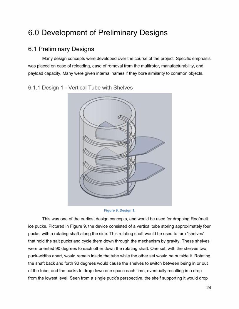
Figure 9. Design 1.
This was one of the earliest design concepts, and would be used for dropping Roofmelt
ice pucks. Pictured in Figure 9, the device consisted of a vertical tube storing approximately four
pucks, with a rotating shaft along the side. This rotating shaft would be used to turn “shelves”
that hold the salt pucks and cycle them down through the mechanism by gravity. These shelves
were oriented 90 degrees to each other down the rotating shaft. One set, with the shelves two
puck-widths apart, would remain inside the tube while the other set would be outside it. Rotating
the shaft back and forth 90 degrees would cause the shelves to switch between being in or out
of the tube, and the pucks to drop down one space each time, eventually resulting in a drop
from the lowest level. Seen from a single puck’s perspective, the shelf supporting it would drop
25
out from under it just as another shelf rotated in its way, one puck-height below (unless that
puck was on the last layer of the device, in which case it would fall completely out the bottom
aperture).
An inherent problem of this design is the reliance on the timing being “just right” so that
one falling puck would not be accompanied by another above it due to its supporting shelf not
rotating underneath it in time. To rectify this, the shelves were offset by less than 90 degrees to
each other, and their shape was changed from a straight blade to a curved one. In this way, as
one puck’s shelf rotated out from underneath it, the shelf above it would already by supporting
the next puck, preventing a premature drop.
However, the shelves had to be shaped as “blades” so that consecutive pucks could be
wedged apart as the shaft rotated between them. Standard roof-melt ice pucks are irregularly-
shaped disks, but are largely flat on their horizontal surfaces. An inability to separate
consecutive pucks could result in a stalled motor or a broken mechanism. This design was
deemed infeasible.
26
6.2.2 Design 2 - Swivel Arm
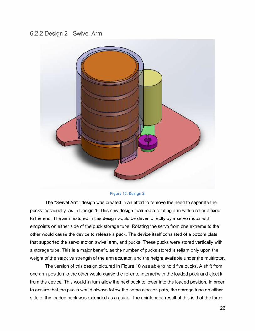
Figure 10. Design 2.
The “Swivel Arm” design was created in an effort to remove the need to separate the
pucks individually, as in Design 1. This new design featured a rotating arm with a roller affixed
to the end. The arm featured in this design would be driven directly by a servo motor with
endpoints on either side of the puck storage tube. Rotating the servo from one extreme to the
other would cause the device to release a puck. The device itself consisted of a bottom plate
that supported the servo motor, swivel arm, and pucks. These pucks were stored vertically with
a storage tube. This is a major benefit, as the number of pucks stored is reliant only upon the
weight of the stack vs strength of the arm actuator, and the height available under the multirotor.
The version of this design pictured in Figure 10 was able to hold five pucks. A shift from
one arm position to the other would cause the roller to interact with the loaded puck and eject it
from the device. This would in turn allow the next puck to lower into the loaded position. In order
to ensure that the pucks would always follow the same ejection path, the storage tube on either
side of the loaded puck was extended as a guide. The unintended result of this is that the force
27
exerted by the swivel arm perpendicular to the release direction would cause the puck to collide
with the walls. This effectively limited the pressure angle of the puck-roller interaction and
therefore the length of the swivel arm itself.
Because it had to have a reduced length, the swivel arm would not be able to properly
eject pucks unless material was removed from below the loaded puck, but by removing this
material, the risk of pucks falling out of the “ready” position prematurely was introduced. The
swiveling arm would be subject to the weight of all the pucks above it while cycling as well,
potentially resulting in jams. While the design itself was simple, it would need further
modification to become feasible.
6.2.3 Design 3 - Crank-Slider
Also incorporating a vertical tube used to hold pucks, this design looked and functioned
similar to the previous, pictured in Figure 10. The key difference was the use of a crank-slider
linkage instead of a single small arm, pushing each puck off individually. The slider itself acted
as the shelf upon which the second puck would rest as the first was dropped, preventing
multiple-drops or jams.
This design was largely feasible, but did have a major drawback. With the puck-to-be-
dropped resting upon the bottom horizontal plate, there was still nothing to stop it from falling
prematurely due to movement of the entire mechanism (the plate would be parallel to the
Earth’s surface, mounted on the bottom of an ostensibly multi-axis-mobile multirotor). Ideas
such as doors held shut by springs or servos were also devised. All of these extras requiring
space at the bottom of an approximately 3in-wide tube did not bode well for the
manufacturability of the mechanism.
28
6.2.4 Design 4 - Rack and Pinion
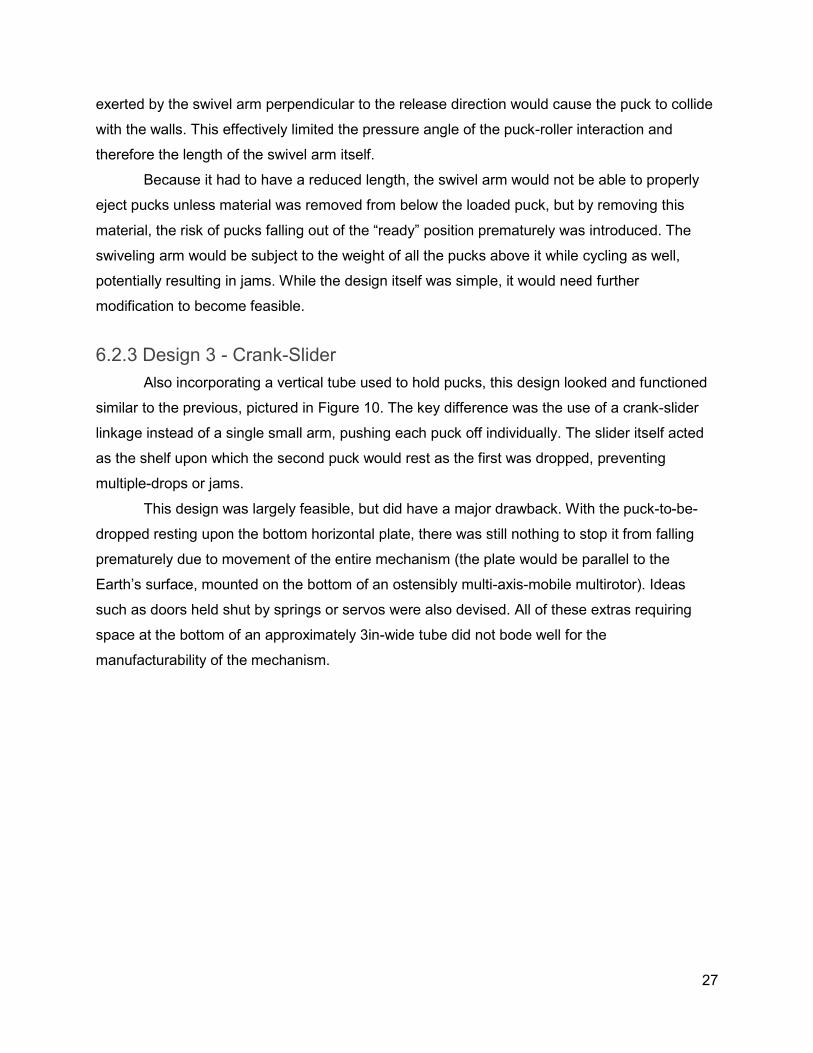
Figure 11. Design 4.
This design was an evolution of the previous one, aiming to solve its premature drop
issues. It made use of a similar storage tube for holding roughly four or five roof melt pucks, but
rather than using a crank-slider to cycle the pucks, it used a rack and pinion system. This
design, shown in Figure 11 and aptly designated the “Rack and Pinion,” would use the rack as
an indexing shelf. Along the side of the mechanism would reside a gear train and a motor or
servo, used to slide the rack back and forth within a guide as the motor turned.
In its extended position, the rack would act as a base for the stored pucks to rest on.
When retracted, a puck would fall into position in front of the rack, ready to be ejected. By
returning to the extended position, the rack would both eject the puck and support the rest of the
pucks above it once again. This design makes use of the weight of the stored pucks to ensure
that the puck in the ejection position wouldn’t be released prematurely.
However, the sliding action of the rack created concerns that a buildup of residual salt
from the Roofmelt ice pucks could cause problems with the mechanism. This could result in
jams and a broken motor. The number of moving parts introduced by the need for a gear train
was also deemed to be a potential problem for consistent operation.
29
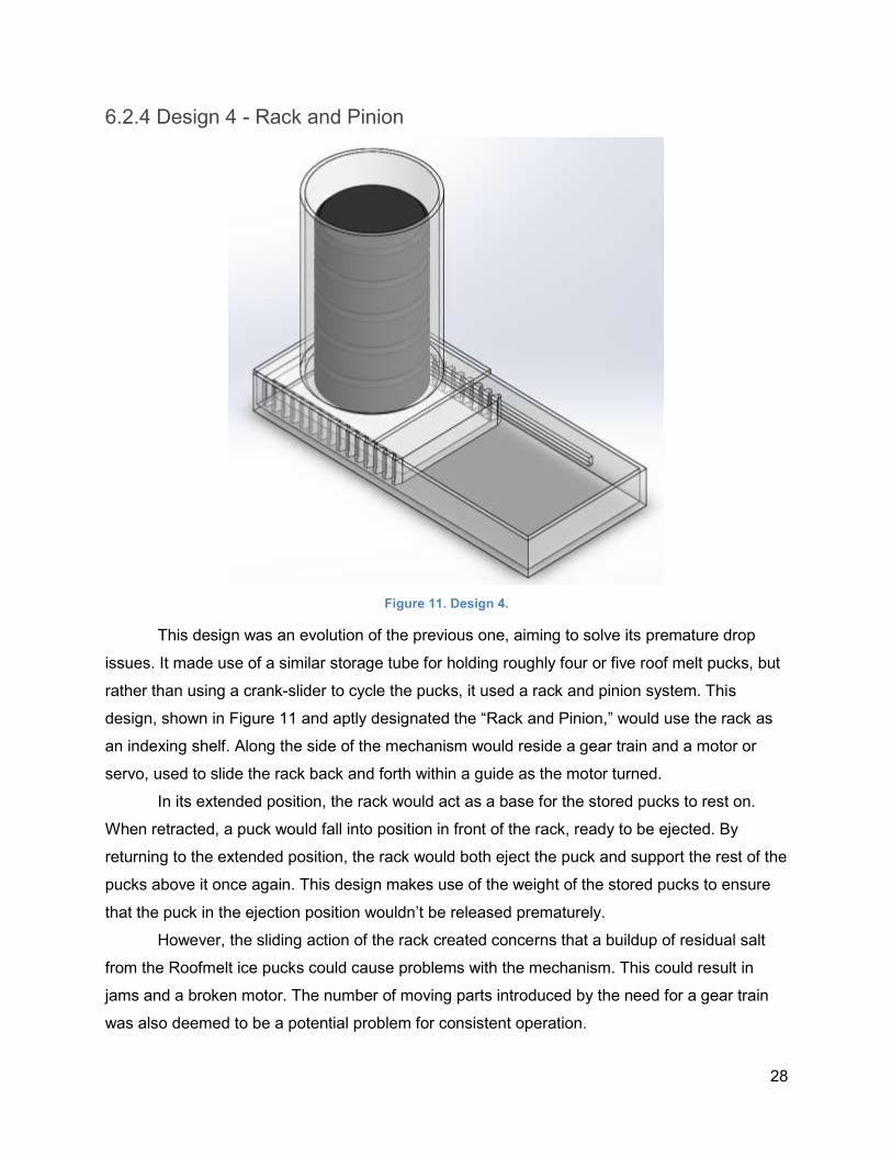
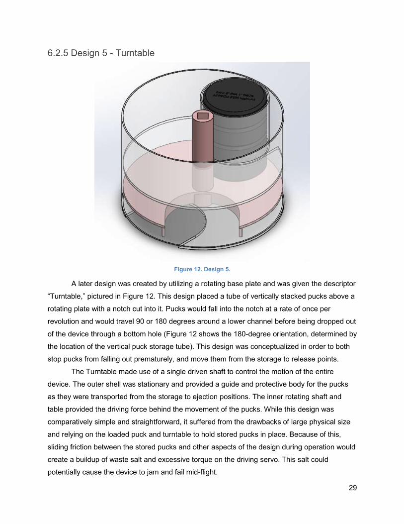
6.2.5 Design 5 - Turntable
Figure 12. Design 5.
A later design was created by utilizing a rotating base plate and was given the descriptor
“Turntable,” pictured in Figure 12. This design placed a tube of vertically stacked pucks above a
rotating plate with a notch cut into it. Pucks would fall into the notch at a rate of once per
revolution and would travel 90 or 180 degrees around a lower channel before being dropped out
of the device through a bottom hole (Figure 12 shows the 180-degree orientation, determined by
the location of the vertical puck storage tube). This design was conceptualized in order to both
stop pucks from falling out prematurely, and move them from the storage to release points.
The Turntable made use of a single driven shaft to control the motion of the entire
device. The outer shell was stationary and provided a guide and protective body for the pucks
as they were transported from the storage to ejection positions. The inner rotating shaft and
table provided the driving force behind the movement of the pucks. While this design was
comparatively simple and straightforward, it suffered from the drawbacks of large physical size
and relying on the loaded puck and turntable to hold stored pucks in place. Because of this,
sliding friction between the stored pucks and other aspects of the design during operation would
create a buildup of waste salt and excessive torque on the driving servo. This salt could
potentially cause the device to jam and fail mid-flight.
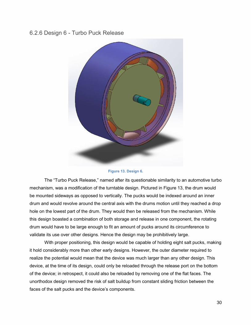
30
6.2.6 Design 6 - Turbo Puck Release
Figure 13. Design 6.
The “Turbo Puck Release,” named after its questionable similarity to an automotive turbo
mechanism, was a modification of the turntable design. Pictured in Figure 13, the drum would
be mounted sideways as opposed to vertically. The pucks would be indexed around an inner
drum and would revolve around the central axis with the drums motion until they reached a drop
hole on the lowest part of the drum. They would then be released from the mechanism. While
this design boasted a combination of both storage and release in one component, the rotating
drum would have to be large enough to fit an amount of pucks around its circumference to
validate its use over other designs. Hence the design may be prohibitively large.
With proper positioning, this design would be capable of holding eight salt pucks, making
it hold considerably more than other early designs. However, the outer diameter required to
realize the potential would mean that the device was much larger than any other design. This
device, at the time of its design, could only be reloaded through the release port on the bottom
of the device; in retrospect, it could also be reloaded by removing one of the flat faces. The
unorthodox design removed the risk of salt buildup from constant sliding friction between the
faces of the salt pucks and the device’s components.
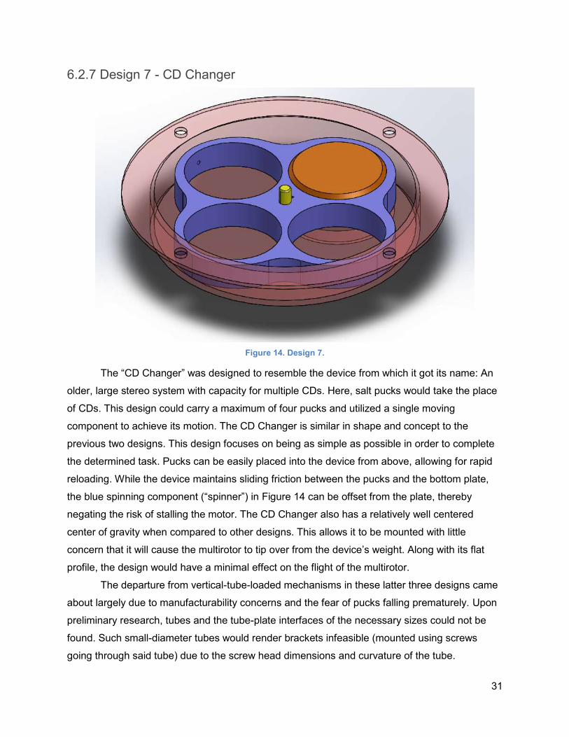
31
6.2.7 Design 7 - CD Changer
Figure 14. Design 7.
The “CD Changer” was designed to resemble the device from which it got its name: An
older, large stereo system with capacity for multiple CDs. Here, salt pucks would take the place
of CDs. This design could carry a maximum of four pucks and utilized a single moving
component to achieve its motion. The CD Changer is similar in shape and concept to the
previous two designs. This design focuses on being as simple as possible in order to complete
the determined task. Pucks can be easily placed into the device from above, allowing for rapid
reloading. While the device maintains sliding friction between the pucks and the bottom plate,
the blue spinning component (“spinner”) in Figure 14 can be offset from the plate, thereby
negating the risk of stalling the motor. The CD Changer also has a relatively well centered
center of gravity when compared to other designs. This allows it to be mounted with little
concern that it will cause the multirotor to tip over from the device’s weight. Along with its flat
profile, the design would have a minimal effect on the flight of the multirotor.
The departure from vertical-tube-loaded mechanisms in these latter three designs came
about largely due to manufacturability concerns and the fear of pucks falling prematurely. Upon
preliminary research, tubes and the tube-plate interfaces of the necessary sizes could not be
found. Such small-diameter tubes would render brackets infeasible (mounted using screws
going through said tube) due to the screw head dimensions and curvature of the tube.
32
Pucks slipping out of the pre-drop position would be nearly impossible with this design,
due to the presence of the tubular body and relatively small diameter of the drop hole (which
pucks are often adjacent to). This design also retains the ability for a high capacity. In theory,
the pucks could be stacked in layers, with a plate separating each layer. The limiting factors
here would be the precision with which the spinners can be moved and the design of those
separating plates, which are crucial to allowing second-layer pucks to fall down into the main
first layer.
A derivative of this design ended up being the final prototype. This final design had two
layers (and one separating plate) for a total capacity of seven pucks, in a more compact form-
factor than the Turbo design.
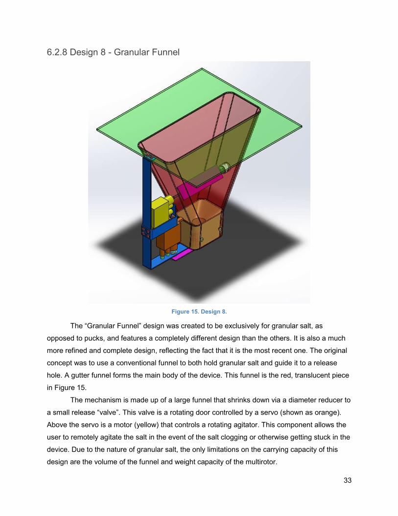
33
6.2.8 Design 8 - Granular Funnel
Figure 15. Design 8.
The “Granular Funnel” design was created to be exclusively for granular salt, as
opposed to pucks, and features a completely different design than the others. It is also a much
more refined and complete design, reflecting the fact that it is the most recent one. The original
concept was to use a conventional funnel to both hold granular salt and guide it to a release
hole. A gutter funnel forms the main body of the device. This funnel is the red, translucent piece
in Figure 15.
The mechanism is made up of a large funnel that shrinks down via a diameter reducer to
a small release “valve”. This valve is a rotating door controlled by a servo (shown as orange).
Above the servo is a motor (yellow) that controls a rotating agitator. This component allows the
user to remotely agitate the salt in the event of the salt clogging or otherwise getting stuck in the
device. Due to the nature of granular salt, the only limitations on the carrying capacity of this
design are the volume of the funnel and weight capacity of the multirotor.
34
The servo only needs to open and close a door, and the motor will only be used on the
rare occasion that the granular salt gets clogged. As a result, power draw is low. This design is
almost completely resistant to the effects of salt buildup as it is designed to pour out salt through
the assistance of gravity. Any considerable salt buildup will be flushed out of the release valve
along with the granular salt. Given its simplicity, this design is highly desirable as a means to
drop granular salt, and no further iteration took place on this front.
Originally, one design that incorporated the ability to drop both forms of salt (pucks and
granular) was sought. It was determined that more salt could be carried while still meeting the
functional specifications by making this separate mechanism. The separate mechanisms would
be rapidly interchangeable instead.
6.2 Weighted Design Matrix
The designs were compared using a set of five weighted criteria. These criteria are as
follows:
● Mass: Weight 0.30
○ Mass is critical in determining whether or not the design can be feasibly carried
by a multirotor and as such, is the most restrictive element on the table.
○ Scoring:
■ 1: Design has a mass of over approx. 2kg
■ 2: Design has a mass between approx. 1.0kg and 2kg
■ 3: Design has mass below approx. 1kg
● Payload: Weight 0.25
○ Payload refers to the amount of pucks or granular salt that can be carried by the
design before needing to land and reload.
○ Scoring:
■ 1: Design can carry 3 or fewer pucks / equivalent granular salt
■ 2: Design can carry 3 to 5 pucks / equivalent granular salt
■ 3: Design can carry 6 or more pucks / equivalent granular salt
● Manufacturability: Weighting 0.20
○ Manufacturability refers to the ease with which the design can be manufactured.
Overly complex designs may function better or be more optimized, but they may
not be able to be repaired quickly and easily should the multirotor crash.
○ Scoring:
35
■ 1: Many components must be manufactured elsewhere, take a long time
to do so, or are difficult to assemble
■ 2: Some components must be manufactured elsewhere, take a moderate
amount of time to do so, or are moderately difficult to assemble
■ 3: Most components can be manufactured without outside aid, take a low
amount of time to do so, or are easy to assemble
● Modularity: Weighting 0.10
○ Modularity is a term used to describe the ease with which the devices can be
broken down or slightly modified to accommodate different salt payloads (puck
form versus granular form), in order to be repaired or to provide flexibility. An
emphasis is placed on the ability of the device to be broken down for repair, as
the plan is to make two separate mechanisms for different salt formats.
○ Scoring:
■ 1: Design cannot be modified for different types of salt / cannot be broken
down
■ 2: Design may be able to accommodate different types of salt with some
difficulty / can be broken down with some difficulty
■ 3: Design requires no refitting to accommodate different types of salt / can
be broken down easily
● Simplicity: Weighting 0.15
○ Simplicity categorizes designs with fewer moving parts as simpler. Fewer moving
parts results in fewer potential failure points, and fewer locations at which salt
may jam the mechanism.
○ Scoring:
■ 1: Design has 4 or more moving parts
■ 2: Design has 2 to 3 moving parts
■ 3: Design has 1 moving parts
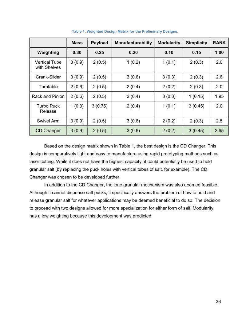
36
Table 1. Weighted Design Matrix for the Preliminary Designs.
Mass Payload Manufacturability Modularity Simplicity RANK
Weighting 0.30 0.25 0.20 0.10 0.15 1.00
Vertical Tube with Shelves
3 (0.9) 2 (0.5) 1 (0.2) 1 (0.1) 2 (0.3) 2.0
Crank-Slider 3 (0.9) 2 (0.5) 3 (0.6) 3 (0.3) 2 (0.3) 2.6
Turntable 2 (0.6) 2 (0.5) 2 (0.4) 2 (0.2) 2 (0.3) 2.0
Rack and Pinion 2 (0.6) 2 (0.5) 2 (0.4) 3 (0.3) 1 (0.15) 1.95
Turbo Puck Release
1 (0.3) 3 (0.75) 2 (0.4) 1 (0.1) 3 (0.45) 2.0
Swivel Arm 3 (0.9) 2 (0.5) 3 (0.6) 2 (0.2) 2 (0.3) 2.5
CD Changer 3 (0.9) 2 (0.5) 3 (0.6) 2 (0.2) 3 (0.45) 2.65
Based on the design matrix shown in Table 1, the best design is the CD Changer. This
design is comparatively light and easy to manufacture using rapid prototyping methods such as
laser cutting. While it does not have the highest capacity, it could potentially be used to hold
granular salt (by replacing the puck holes with vertical tubes of salt, for example). The CD
Changer was chosen to be developed further.
In addition to the CD Changer, the lone granular mechanism was also deemed feasible.
Although it cannot dispense salt pucks, it specifically answers the problem of how to hold and
release granular salt for whatever applications may be deemed beneficial to do so. The decision
to proceed with two designs allowed for more specialization for either form of salt. Modularity
has a low weighting because this development was predicted.
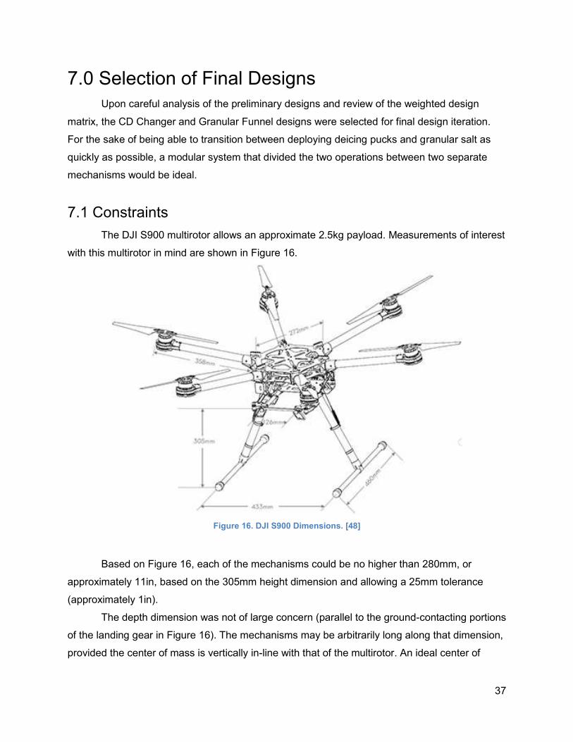
37
7.0 Selection of Final Designs
Upon careful analysis of the preliminary designs and review of the weighted design
matrix, the CD Changer and Granular Funnel designs were selected for final design iteration.
For the sake of being able to transition between deploying deicing pucks and granular salt as
quickly as possible, a modular system that divided the two operations between two separate
mechanisms would be ideal.
7.1 Constraints
The DJI S900 multirotor allows an approximate 2.5kg payload. Measurements of interest
with this multirotor in mind are shown in Figure 16.
Figure 16. DJI S900 Dimensions. [48]
Based on Figure 16, each of the mechanisms could be no higher than 280mm, or
approximately 11in, based on the 305mm height dimension and allowing a 25mm tolerance
(approximately 1in).
The depth dimension was not of large concern (parallel to the ground-contacting portions
of the landing gear in Figure 16). The mechanisms may be arbitrarily long along that dimension,
provided the center of mass is vertically in-line with that of the multirotor. An ideal center of
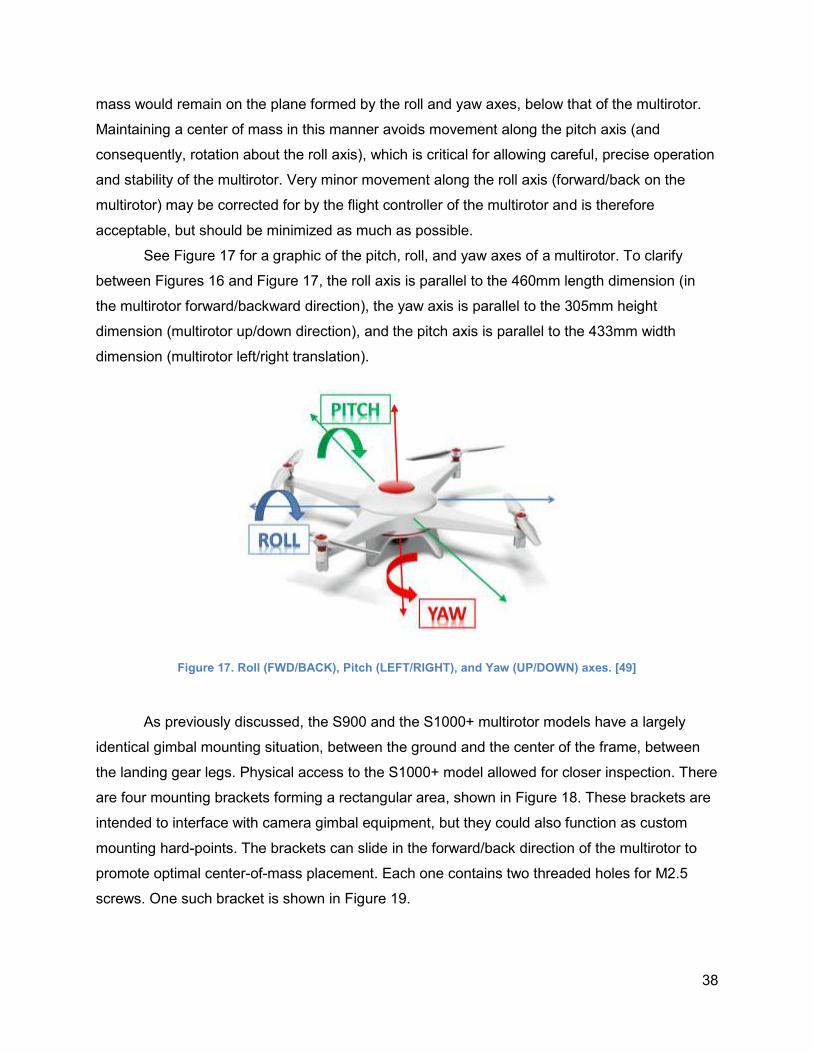
38
mass would remain on the plane formed by the roll and yaw axes, below that of the multirotor.
Maintaining a center of mass in this manner avoids movement along the pitch axis (and
consequently, rotation about the roll axis), which is critical for allowing careful, precise operation
and stability of the multirotor. Very minor movement along the roll axis (forward/back on the
multirotor) may be corrected for by the flight controller of the multirotor and is therefore
acceptable, but should be minimized as much as possible.
See Figure 17 for a graphic of the pitch, roll, and yaw axes of a multirotor. To clarify
between Figures 16 and Figure 17, the roll axis is parallel to the 460mm length dimension (in
the multirotor forward/backward direction), the yaw axis is parallel to the 305mm height
dimension (multirotor up/down direction), and the pitch axis is parallel to the 433mm width
dimension (multirotor left/right translation).
Figure 17. Roll (FWD/BACK), Pitch (LEFT/RIGHT), and Yaw (UP/DOWN) axes. [49]
As previously discussed, the S900 and the S1000+ multirotor models have a largely
identical gimbal mounting situation, between the ground and the center of the frame, between
the landing gear legs. Physical access to the S1000+ model allowed for closer inspection. There
are four mounting brackets forming a rectangular area, shown in Figure 18. These brackets are
intended to interface with camera gimbal equipment, but they could also function as custom
mounting hard-points. The brackets can slide in the forward/back direction of the multirotor to
promote optimal center-of-mass placement. Each one contains two threaded holes for M2.5
screws. One such bracket is shown in Figure 19.
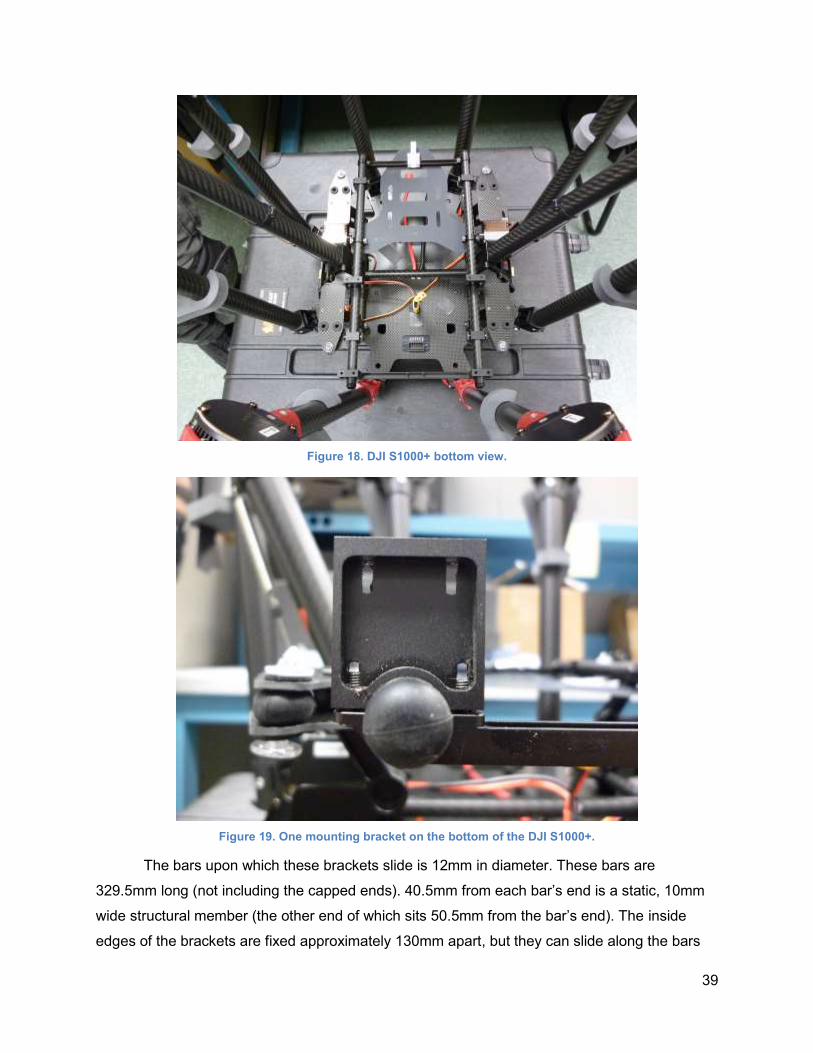
39
Figure 18. DJI S1000+ bottom view.
Figure 19. One mounting bracket on the bottom of the DJI S1000+.
The bars upon which these brackets slide is 12mm in diameter. These bars are
329.5mm long (not including the capped ends). 40.5mm from each bar’s end is a static, 10mm
wide structural member (the other end of which sits 50.5mm from the bar’s end). The inside
edges of the brackets are fixed approximately 130mm apart, but they can slide along the bars
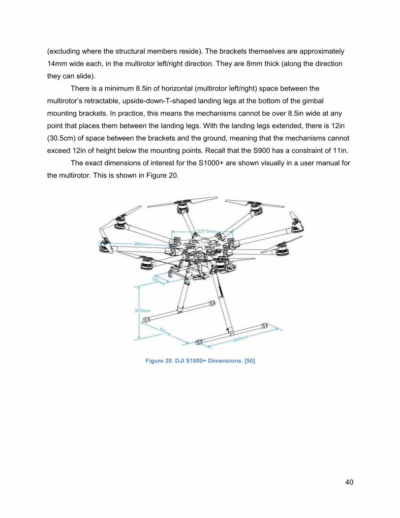
40
(excluding where the structural members reside). The brackets themselves are approximately
14mm wide each, in the multirotor left/right direction. They are 8mm thick (along the direction
they can slide).
There is a minimum 8.5in of horizontal (multirotor left/right) space between the
multirotor’s retractable, upside-down-T-shaped landing legs at the bottom of the gimbal
mounting brackets. In practice, this means the mechanisms cannot be over 8.5in wide at any
point that places them between the landing legs. With the landing legs extended, there is 12in
(30.5cm) of space between the brackets and the ground, meaning that the mechanisms cannot
exceed 12in of height below the mounting points. Recall that the S900 has a constraint of 11in.
The exact dimensions of interest for the S1000+ are shown visually in a user manual for
the multirotor. This is shown in Figure 20.
Figure 20. DJI S1000+ Dimensions. [50]
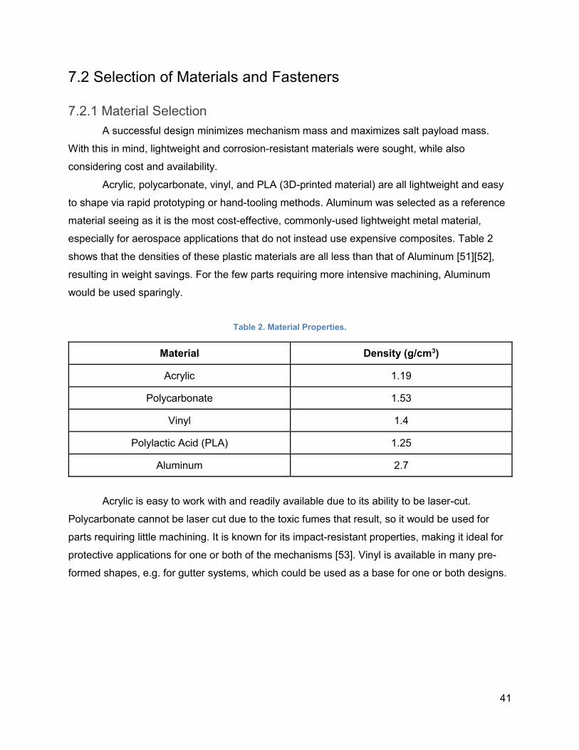
41
7.2 Selection of Materials and Fasteners
7.2.1 Material Selection
A successful design minimizes mechanism mass and maximizes salt payload mass.
With this in mind, lightweight and corrosion-resistant materials were sought, while also
considering cost and availability.
Acrylic, polycarbonate, vinyl, and PLA (3D-printed material) are all lightweight and easy
to shape via rapid prototyping or hand-tooling methods. Aluminum was selected as a reference
material seeing as it is the most cost-effective, commonly-used lightweight metal material,
especially for aerospace applications that do not instead use expensive composites. Table 2
shows that the densities of these plastic materials are all less than that of Aluminum [51][52],
resulting in weight savings. For the few parts requiring more intensive machining, Aluminum
would be used sparingly.
Table 2. Material Properties.
Material Density (g/cm3)
Acrylic 1.19
Polycarbonate 1.53
Vinyl 1.4
Polylactic Acid (PLA) 1.25
Aluminum 2.7
Acrylic is easy to work with and readily available due to its ability to be laser-cut.
Polycarbonate cannot be laser cut due to the toxic fumes that result, so it would be used for
parts requiring little machining. It is known for its impact-resistant properties, making it ideal for
protective applications for one or both of the mechanisms [53]. Vinyl is available in many pre-
formed shapes, e.g. for gutter systems, which could be used as a base for one or both designs.
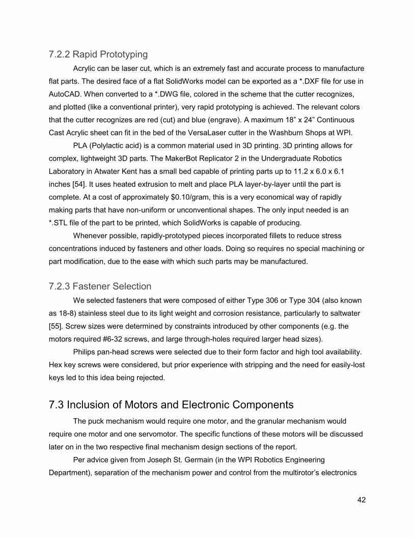
42
7.2.2 Rapid Prototyping
Acrylic can be laser cut, which is an extremely fast and accurate process to manufacture
flat parts. The desired face of a flat SolidWorks model can be exported as a *.DXF file for use in
AutoCAD. When converted to a *.DWG file, colored in the scheme that the cutter recognizes,
and plotted (like a conventional printer), very rapid prototyping is achieved. The relevant colors
that the cutter recognizes are red (cut) and blue (engrave). A maximum 18” x 24” Continuous
Cast Acrylic sheet can fit in the bed of the VersaLaser cutter in the Washburn Shops at WPI.
PLA (Polylactic acid) is a common material used in 3D printing. 3D printing allows for
complex, lightweight 3D parts. The MakerBot Replicator 2 in the Undergraduate Robotics
Laboratory in Atwater Kent has a small bed capable of printing parts up to 11.2 x 6.0 x 6.1
inches [54]. It uses heated extrusion to melt and place PLA layer-by-layer until the part is
complete. At a cost of approximately $0.10/gram, this is a very economical way of rapidly
making parts that have non-uniform or unconventional shapes. The only input needed is an
*.STL file of the part to be printed, which SolidWorks is capable of producing.
Whenever possible, rapidly-prototyped pieces incorporated fillets to reduce stress
concentrations induced by fasteners and other loads. Doing so requires no special machining or
part modification, due to the ease with which such parts may be manufactured.
7.2.3 Fastener Selection
We selected fasteners that were composed of either Type 306 or Type 304 (also known
as 18-8) stainless steel due to its light weight and corrosion resistance, particularly to saltwater
[55]. Screw sizes were determined by constraints introduced by other components (e.g. the
motors required #6-32 screws, and large through-holes required larger head sizes).
Philips pan-head screws were selected due to their form factor and high tool availability.
Hex key screws were considered, but prior experience with stripping and the need for easily-lost
keys led to this idea being rejected.
7.3 Inclusion of Motors and Electronic Components
The puck mechanism would require one motor, and the granular mechanism would
require one motor and one servomotor. The specific functions of these motors will be discussed
later on in the two respective final mechanism design sections of the report.
Per advice given from Joseph St. Germain (in the WPI Robotics Engineering
Department), separation of the mechanism power and control from the multirotor’s electronics
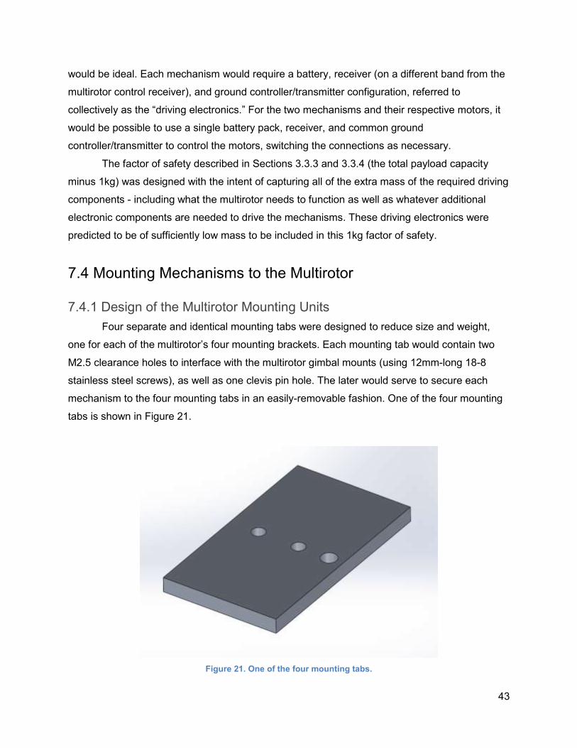
43
would be ideal. Each mechanism would require a battery, receiver (on a different band from the
multirotor control receiver), and ground controller/transmitter configuration, referred to
collectively as the “driving electronics.” For the two mechanisms and their respective motors, it
would be possible to use a single battery pack, receiver, and common ground
controller/transmitter to control the motors, switching the connections as necessary.
The factor of safety described in Sections 3.3.3 and 3.3.4 (the total payload capacity
minus 1kg) was designed with the intent of capturing all of the extra mass of the required driving
components - including what the multirotor needs to function as well as whatever additional
electronic components are needed to drive the mechanisms. These driving electronics were
predicted to be of sufficiently low mass to be included in this 1kg factor of safety.
7.4 Mounting Mechanisms to the Multirotor
7.4.1 Design of the Multirotor Mounting Units
Four separate and identical mounting tabs were designed to reduce size and weight,
one for each of the multirotor’s four mounting brackets. Each mounting tab would contain two
M2.5 clearance holes to interface with the multirotor gimbal mounts (using 12mm-long 18-8
stainless steel screws), as well as one clevis pin hole. The later would serve to secure each
mechanism to the four mounting tabs in an easily-removable fashion. One of the four mounting
tabs is shown in Figure 21.
Figure 21. One of the four mounting tabs.
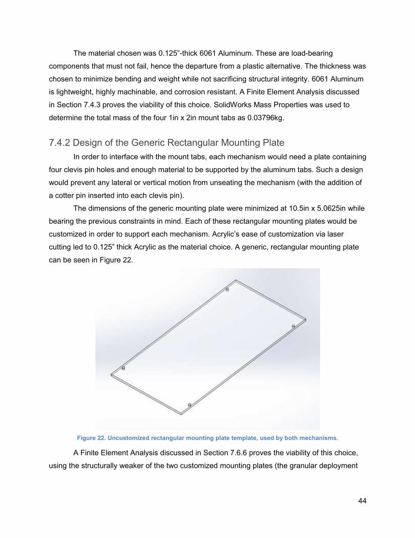
44
The material chosen was 0.125”-thick 6061 Aluminum. These are load-bearing
components that must not fail, hence the departure from a plastic alternative. The thickness was
chosen to minimize bending and weight while not sacrificing structural integrity. 6061 Aluminum
is lightweight, highly machinable, and corrosion resistant. A Finite Element Analysis discussed
in Section 7.4.3 proves the viability of this choice. SolidWorks Mass Properties was used to
determine the total mass of the four 1in x 2in mount tabs as 0.03796kg.
7.4.2 Design of the Generic Rectangular Mounting Plate
In order to interface with the mount tabs, each mechanism would need a plate containing
four clevis pin holes and enough material to be supported by the aluminum tabs. Such a design
would prevent any lateral or vertical motion from unseating the mechanism (with the addition of
a cotter pin inserted into each clevis pin).
The dimensions of the generic mounting plate were minimized at 10.5in x 5.0625in while
bearing the previous constraints in mind. Each of these rectangular mounting plates would be
customized in order to support each mechanism. Acrylic’s ease of customization via laser
cutting led to 0.125” thick Acrylic as the material choice. A generic, rectangular mounting plate
can be seen in Figure 22.
Figure 22. Uncustomized rectangular mounting plate template, used by both mechanisms.
A Finite Element Analysis discussed in Section 7.6.6 proves the viability of this choice,
using the structurally weaker of the two customized mounting plates (the granular deployment
45
mechanism plate). SolidWorks Mass Properties was used to determine the mass of one generic
mount plate as 0.13052kg.
Figure 23 shows how the multirotor mounting tabs and plate interact, and how the
mounting tabs connect to the multirotor brackets. The blue portion of the assembly is a model of
the multirotor gimbal mounting apparatus, to which the mounting tabs attach via the M2.5
screws.
Figure 23. Rectangular mount plate, as it interfaces with the mounting tabs and S1000+ gimbal mounting brackets.
7.4.3 Finite Element Analysis of the Mounting Units
To ensure the integrity of the aluminum mount tabs, a Finite Element Analysis was run
using SolidWorks SimulationXpress. A maximum payload of 2.5kg results in 0.625kg of
supported mass per mounting tab. A factor of safety of three was employed, for a conservative
total of 1.875kg supported mass per mounting tab.
In the SolidWorks simulation, the mounting tab was fixtured in the area where it comes
in contact with the multirotor-side mounting bracket, and in the areas where the screw heads
contact the underside of the mounting tab. An equivalent force of 18.39375N (the effect of
gravity on the 1.875kg payload) was applied over the area where the surface of the multirotor-
side mounting bracket comes in contact with the mounting tab to simulate the potential weight of
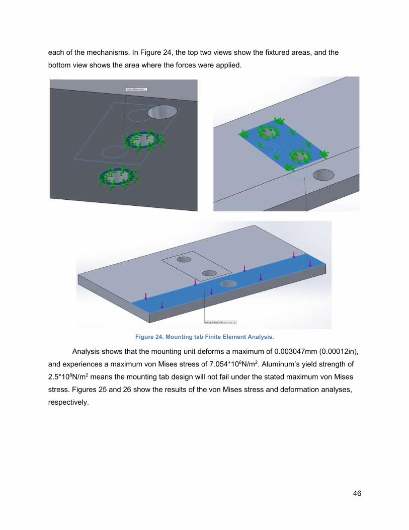
46
each of the mechanisms. In Figure 24, the top two views show the fixtured areas, and the
bottom view shows the area where the forces were applied.
Figure 24. Mounting tab Finite Element Analysis.
Analysis shows that the mounting unit deforms a maximum of 0.003047mm (0.00012in),
and experiences a maximum von Mises stress of 7.054*106N/m2. Aluminum’s yield strength of
2.5*108N/m2 means the mounting tab design will not fail under the stated maximum von Mises
stress. Figures 25 and 26 show the results of the von Mises stress and deformation analyses,
respectively.
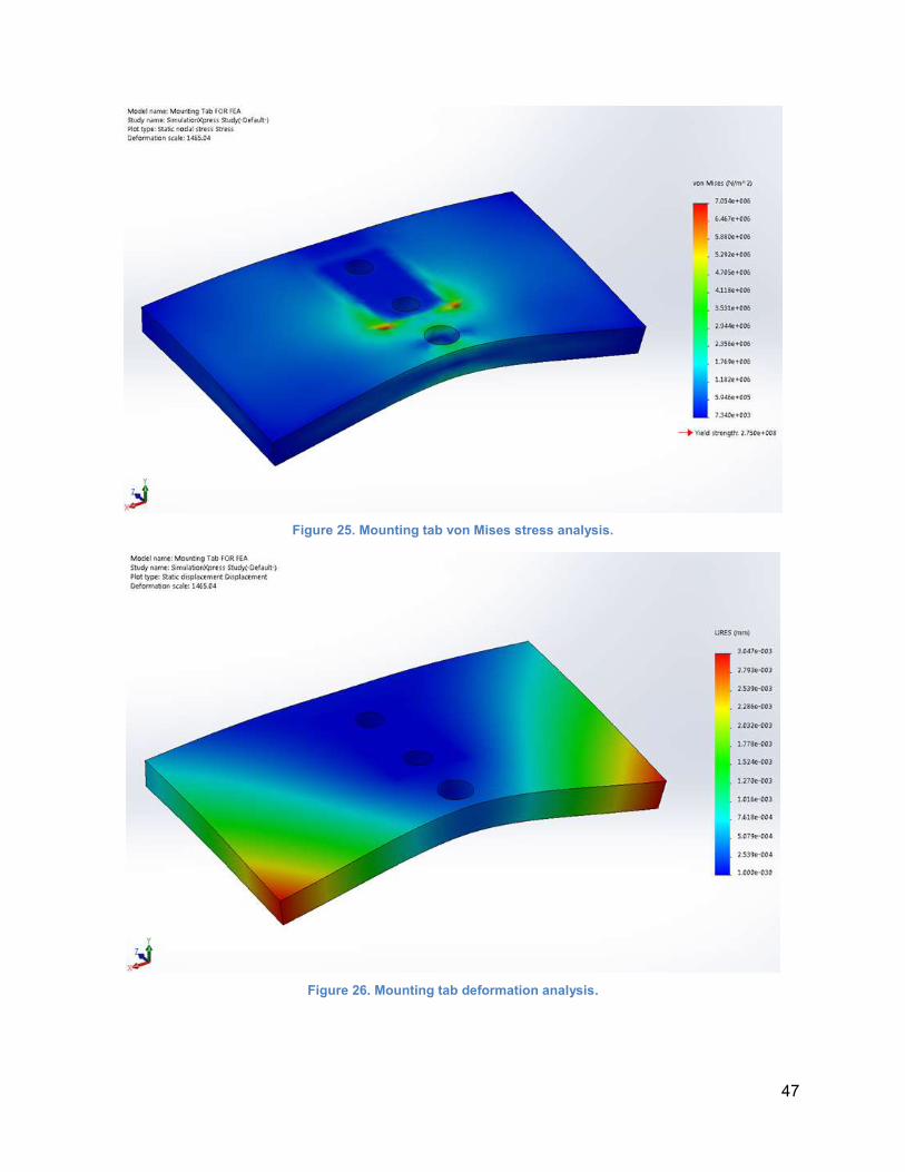
47
Figure 25. Mounting tab von Mises stress analysis.
Figure 26. Mounting tab deformation analysis.
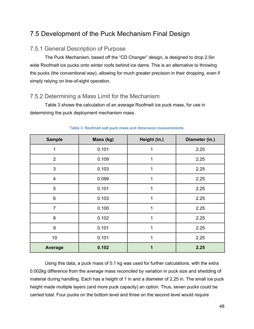
48
7.5 Development of the Puck Mechanism Final Design
7.5.1 General Description of Purpose
The Puck Mechanism, based off the “CD Changer” design, is designed to drop 2.5in
wide Roofmelt ice pucks onto winter roofs behind ice dams. This is an alternative to throwing
the pucks (the conventional way), allowing for much greater precision in their dropping, even if
simply relying on line-of-sight operation.
7.5.2 Determining a Mass Limit for the Mechanism
Table 3 shows the calculation of an average Roofmelt ice puck mass, for use in
determining the puck deployment mechanism mass.
Table 3. Roofmelt salt puck mass and dimension measurements.
Sample Mass (kg) Height (in.) Diameter (in.)
1 0.101 1 2.25
2 0.109 1 2.25
3 0.103 1 2.25
4 0.099 1 2.25
5 0.101 1 2.25
6 0.103 1 2.25
7 0.100 1 2.25
8 0.102 1 2.25
9 0.101 1 2.25
10 0.101 1 2.25
Average 0.102 1 2.25
Using this data, a puck mass of 0.1 kg was used for further calculations, with the extra
0.002kg difference from the average mass reconciled by variation in puck size and shedding of
material during handling. Each has a height of 1 in and a diameter of 2.25 in. The small ice puck
height made multiple layers (and more puck capacity) an option. Thus, seven pucks could be
carried total. Four pucks on the bottom level and three on the second level would require
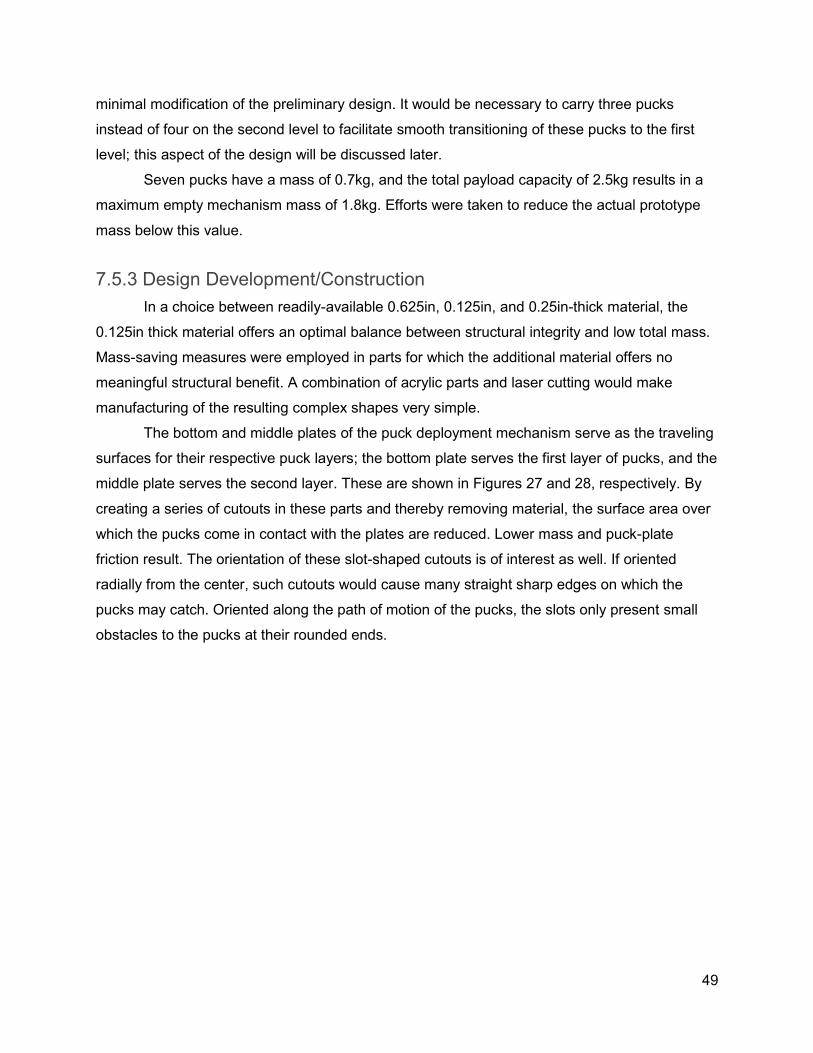
49
minimal modification of the preliminary design. It would be necessary to carry three pucks
instead of four on the second level to facilitate smooth transitioning of these pucks to the first
level; this aspect of the design will be discussed later.
Seven pucks have a mass of 0.7kg, and the total payload capacity of 2.5kg results in a
maximum empty mechanism mass of 1.8kg. Efforts were taken to reduce the actual prototype
mass below this value.
7.5.3 Design Development/Construction
In a choice between readily-available 0.625in, 0.125in, and 0.25in-thick material, the
0.125in thick material offers an optimal balance between structural integrity and low total mass.
Mass-saving measures were employed in parts for which the additional material offers no
meaningful structural benefit. A combination of acrylic parts and laser cutting would make
manufacturing of the resulting complex shapes very simple.
The bottom and middle plates of the puck deployment mechanism serve as the traveling
surfaces for their respective puck layers; the bottom plate serves the first layer of pucks, and the
middle plate serves the second layer. These are shown in Figures 27 and 28, respectively. By
creating a series of cutouts in these parts and thereby removing material, the surface area over
which the pucks come in contact with the plates are reduced. Lower mass and puck-plate
friction result. The orientation of these slot-shaped cutouts is of interest as well. If oriented
radially from the center, such cutouts would cause many straight sharp edges on which the
pucks may catch. Oriented along the path of motion of the pucks, the slots only present small
obstacles to the pucks at their rounded ends.
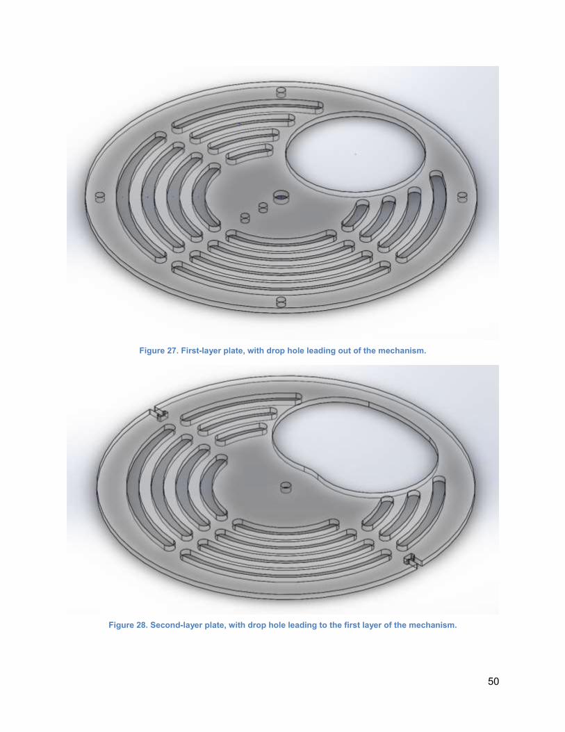
50
Figure 27. First-layer plate, with drop hole leading out of the mechanism.
Figure 28. Second-layer plate, with drop hole leading to the first layer of the mechanism.
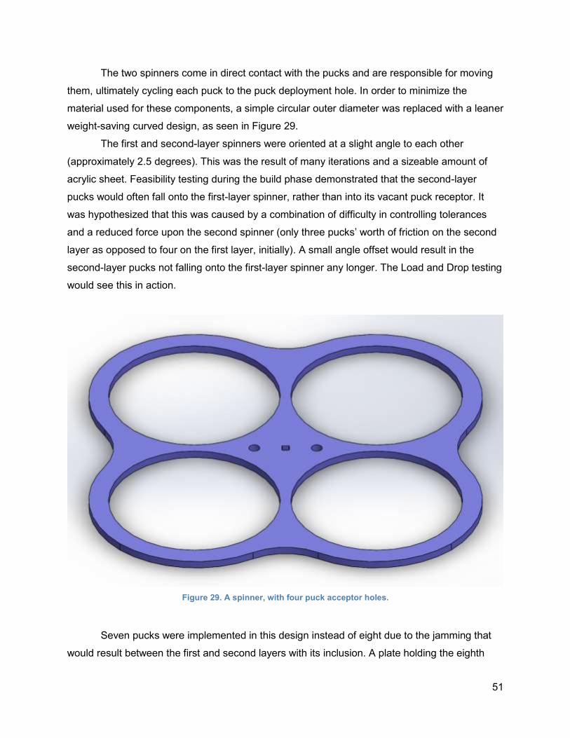
51
The two spinners come in direct contact with the pucks and are responsible for moving
them, ultimately cycling each puck to the puck deployment hole. In order to minimize the
material used for these components, a simple circular outer diameter was replaced with a leaner
weight-saving curved design, as seen in Figure 29.
The first and second-layer spinners were oriented at a slight angle to each other
(approximately 2.5 degrees). This was the result of many iterations and a sizeable amount of
acrylic sheet. Feasibility testing during the build phase demonstrated that the second-layer
pucks would often fall onto the first-layer spinner, rather than into its vacant puck receptor. It
was hypothesized that this was caused by a combination of difficulty in controlling tolerances
and a reduced force upon the second spinner (only three pucks’ worth of friction on the second
layer as opposed to four on the first layer, initially). A small angle offset would result in the
second-layer pucks not falling onto the first-layer spinner any longer. The Load and Drop testing
would see this in action.
Figure 29. A spinner, with four puck acceptor holes.
Seven pucks were implemented in this design instead of eight due to the jamming that
would result between the first and second layers with its inclusion. A plate holding the eighth
52
puck and a rotating arm above the second layer could be used to rectify this, but a small angle
of 17.74 degrees tilt would destabilize this puck. The shelf was still designed and implemented,
with the alternative application of keeping pucks from tilting and jamming the mechanism while
falling from the second to first layer.
One more key consideration that was kept in mind while developing the final puck
mechanism was maintaining a center of mass along the plane formed by the multirotors roll and
yaw axes, as discussed in Section 7.1 of the report. This would ensure stable operation of the
multirotor as it transports pucks up to the ice dam. To achieve this, the mechanism was
developed to be symmetrical about this plane. Relevant calculations are reported further on in
the report with regards to the shifting of the center of mass as pucks cycle through the device.
An exploded view of the entire assembly is shown in Figure 30. In order, the parts are:
1. Top plate, used to stop pucks from tilting as they fall from the second to first layer
2. Second-layer salt pucks x3
3. Second-layer spinner
4. Second-layer plate (middle plate) with drop hole to first layer
5. First-layer salt pucks x4
6. First-layer spinner
7. First-layer plate (bottom plate) with drop hole to roof
8. Axle
9. Mechanism shell
10. Motor clutch, to prevent breaking the motor under high-torque conditions
11. Motor (VEX 393)
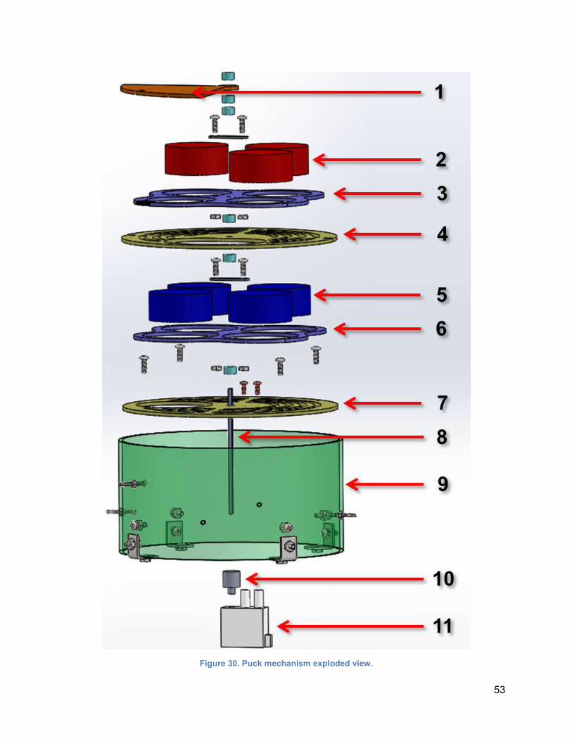
53
Figure 30. Puck mechanism exploded view.
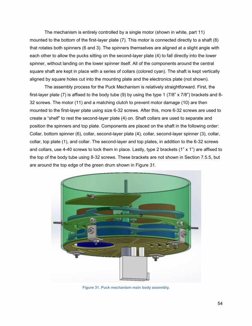
54
The mechanism is entirely controlled by a single motor (shown in white, part 11)
mounted to the bottom of the first-layer plate (7). This motor is connected directly to a shaft (8)
that rotates both spinners (6 and 3). The spinners themselves are aligned at a slight angle with
each other to allow the pucks sitting on the second-layer plate (4) to fall directly into the lower
spinner, without landing on the lower spinner itself. All of the components around the central
square shaft are kept in place with a series of collars (colored cyan). The shaft is kept vertically
aligned by square holes cut into the mounting plate and the electronics plate (not shown).
The assembly process for the Puck Mechanism is relatively straightforward. First, the
first-layer plate (7) is affixed to the body tube (9) by using the type 1 (7/8” x 7/8”) brackets and 8-
32 screws. The motor (11) and a matching clutch to prevent motor damage (10) are then
mounted to the first-layer plate using size 6-32 screws. After this, more 6-32 screws are used to
create a “shelf” to rest the second-layer plate (4) on. Shaft collars are used to separate and
position the spinners and top plate. Components are placed on the shaft in the following order:
Collar, bottom spinner (6), collar, second-layer plate (4), collar, second-layer spinner (3), collar,
collar, top plate (1), and collar. The second-layer and top plates, in addition to the 6-32 screws
and collars, use 4-40 screws to lock them in place. Lastly, type 2 brackets (1” x 1”) are affixed to
the top of the body tube using 8-32 screws. These brackets are not shown in Section 7.5.5, but
are around the top edge of the green drum shown in Figure 31.
Figure 31. Puck mechanism main body assembly.
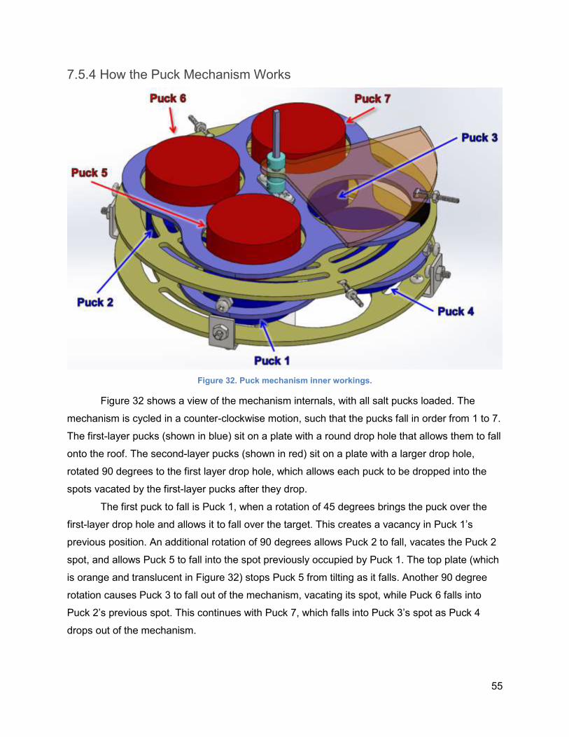
55
7.5.4 How the Puck Mechanism Works
Figure 32. Puck mechanism inner workings.
Figure 32 shows a view of the mechanism internals, with all salt pucks loaded. The
mechanism is cycled in a counter-clockwise motion, such that the pucks fall in order from 1 to 7.
The first-layer pucks (shown in blue) sit on a plate with a round drop hole that allows them to fall
onto the roof. The second-layer pucks (shown in red) sit on a plate with a larger drop hole,
rotated 90 degrees to the first layer drop hole, which allows each puck to be dropped into the
spots vacated by the first-layer pucks after they drop.
The first puck to fall is Puck 1, when a rotation of 45 degrees brings the puck over the
first-layer drop hole and allows it to fall over the target. This creates a vacancy in Puck 1’s
previous position. An additional rotation of 90 degrees allows Puck 2 to fall, vacates the Puck 2
spot, and allows Puck 5 to fall into the spot previously occupied by Puck 1. The top plate (which
is orange and translucent in Figure 32) stops Puck 5 from tilting as it falls. Another 90 degree
rotation causes Puck 3 to fall out of the mechanism, vacating its spot, while Puck 6 falls into
Puck 2’s previous spot. This continues with Puck 7, which falls into Puck 3’s spot as Puck 4
drops out of the mechanism.
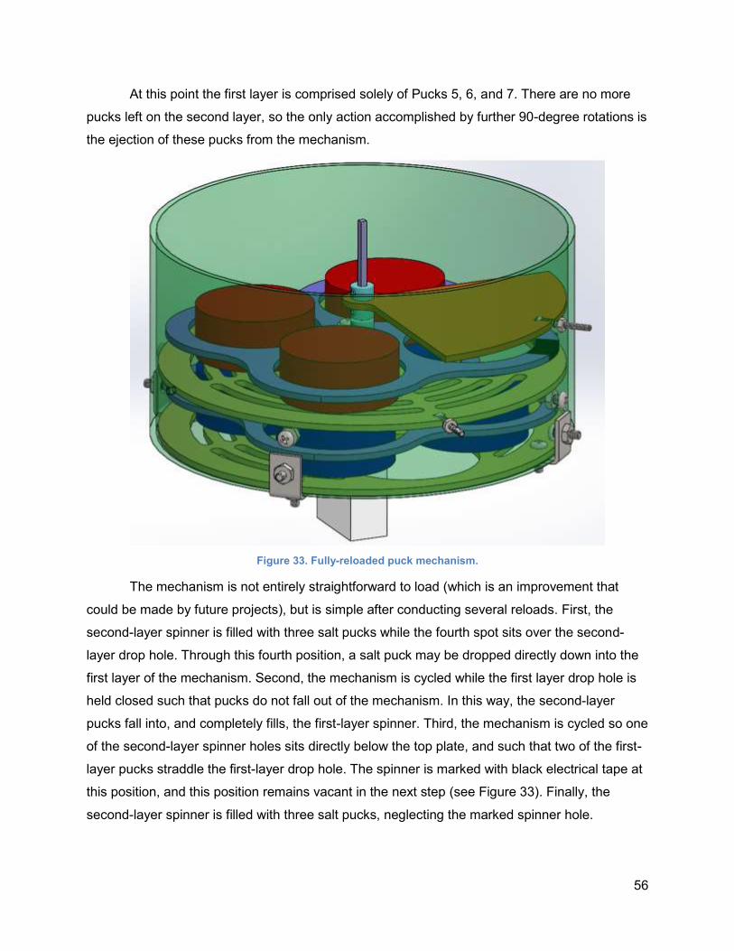
56
At this point the first layer is comprised solely of Pucks 5, 6, and 7. There are no more
pucks left on the second layer, so the only action accomplished by further 90-degree rotations is
the ejection of these pucks from the mechanism.
Figure 33. Fully-reloaded puck mechanism.
The mechanism is not entirely straightforward to load (which is an improvement that
could be made by future projects), but is simple after conducting several reloads. First, the
second-layer spinner is filled with three salt pucks while the fourth spot sits over the second-
layer drop hole. Through this fourth position, a salt puck may be dropped directly down into the
first layer of the mechanism. Second, the mechanism is cycled while the first layer drop hole is
held closed such that pucks do not fall out of the mechanism. In this way, the second-layer
pucks fall into, and completely fills, the first-layer spinner. Third, the mechanism is cycled so one
of the second-layer spinner holes sits directly below the top plate, and such that two of the first-
layer pucks straddle the first-layer drop hole. The spinner is marked with black electrical tape at
this position, and this position remains vacant in the next step (see Figure 33). Finally, the
second-layer spinner is filled with three salt pucks, neglecting the marked spinner hole.

57
Inherent in the reloading process is the act of first removing the mechanism from the
multirotor (removing the Clevis pins holding it onto the mount tabs) and then removing the
mount plate from the mechanism. After reloading, the mount plate is replaced and the
mechanism is mounted back onto the multirotor. This mount plate, and the process used to
remove and replace it, is shown in Figure 34 in the following section.
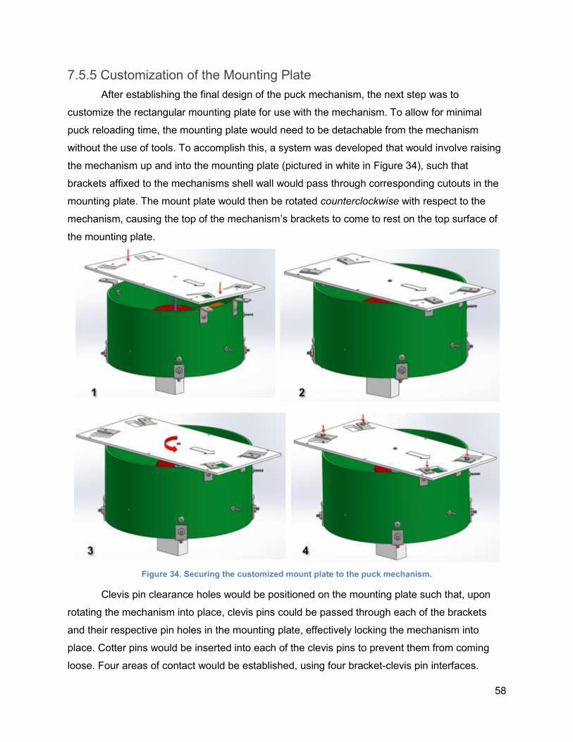
58
7.5.5 Customization of the Mounting Plate
After establishing the final design of the puck mechanism, the next step was to
customize the rectangular mounting plate for use with the mechanism. To allow for minimal
puck reloading time, the mounting plate would need to be detachable from the mechanism
without the use of tools. To accomplish this, a system was developed that would involve raising
the mechanism up and into the mounting plate (pictured in white in Figure 34), such that
brackets affixed to the mechanisms shell wall would pass through corresponding cutouts in the
mounting plate. The mount plate would then be rotated counterclockwise with respect to the
mechanism, causing the top of the mechanism’s brackets to come to rest on the top surface of
the mounting plate.
Figure 34. Securing the customized mount plate to the puck mechanism.
Clevis pin clearance holes would be positioned on the mounting plate such that, upon
rotating the mechanism into place, clevis pins could be passed through each of the brackets
and their respective pin holes in the mounting plate, effectively locking the mechanism into
place. Cotter pins would be inserted into each of the clevis pins to prevent them from coming
loose. Four areas of contact would be established, using four bracket-clevis pin interfaces.
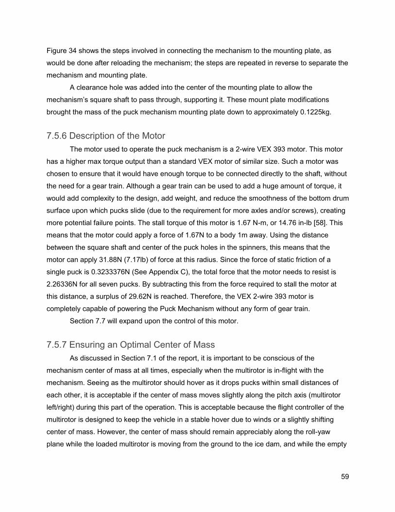
59
Figure 34 shows the steps involved in connecting the mechanism to the mounting plate, as
would be done after reloading the mechanism; the steps are repeated in reverse to separate the
mechanism and mounting plate.
A clearance hole was added into the center of the mounting plate to allow the
mechanism’s square shaft to pass through, supporting it. These mount plate modifications
brought the mass of the puck mechanism mounting plate down to approximately 0.1225kg.
7.5.6 Description of the Motor
The motor used to operate the puck mechanism is a 2-wire VEX 393 motor. This motor
has a higher max torque output than a standard VEX motor of similar size. Such a motor was
chosen to ensure that it would have enough torque to be connected directly to the shaft, without
the need for a gear train. Although a gear train can be used to add a huge amount of torque, it
would add complexity to the design, add weight, and reduce the smoothness of the bottom drum
surface upon which pucks slide (due to the requirement for more axles and/or screws), creating
more potential failure points. The stall torque of this motor is 1.67 N-m, or 14.76 in-lb [58]. This
means that the motor could apply a force of 1.67N to a body 1m away. Using the distance
between the square shaft and center of the puck holes in the spinners, this means that the
motor can apply 31.88N (7.17lb) of force at this radius. Since the force of static friction of a
single puck is 0.3233376N (See Appendix C), the total force that the motor needs to resist is
2.26336N for all seven pucks. By subtracting this from the force required to stall the motor at
this distance, a surplus of 29.62N is reached. Therefore, the VEX 2-wire 393 motor is
completely capable of powering the Puck Mechanism without any form of gear train.
Section 7.7 will expand upon the control of this motor.
7.5.7 Ensuring an Optimal Center of Mass
As discussed in Section 7.1 of the report, it is important to be conscious of the
mechanism center of mass at all times, especially when the multirotor is in-flight with the
mechanism. Seeing as the multirotor should hover as it drops pucks within small distances of
each other, it is acceptable if the center of mass moves slightly along the pitch axis (multirotor
left/right) during this part of the operation. This is acceptable because the flight controller of the
multirotor is designed to keep the vehicle in a stable hover due to winds or a slightly shifting
center of mass. However, the center of mass should remain appreciably along the roll-yaw
plane while the loaded multirotor is moving from the ground to the ice dam, and while the empty
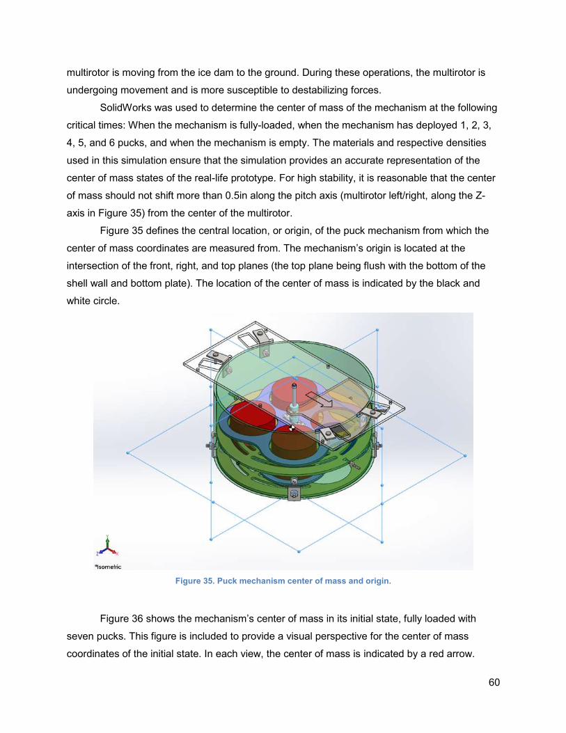
60
multirotor is moving from the ice dam to the ground. During these operations, the multirotor is
undergoing movement and is more susceptible to destabilizing forces.
SolidWorks was used to determine the center of mass of the mechanism at the following
critical times: When the mechanism is fully-loaded, when the mechanism has deployed 1, 2, 3,
4, 5, and 6 pucks, and when the mechanism is empty. The materials and respective densities
used in this simulation ensure that the simulation provides an accurate representation of the
center of mass states of the real-life prototype. For high stability, it is reasonable that the center
of mass should not shift more than 0.5in along the pitch axis (multirotor left/right, along the Z-
axis in Figure 35) from the center of the multirotor.
Figure 35 defines the central location, or origin, of the puck mechanism from which the
center of mass coordinates are measured from. The mechanism’s origin is located at the
intersection of the front, right, and top planes (the top plane being flush with the bottom of the
shell wall and bottom plate). The location of the center of mass is indicated by the black and
white circle.
Figure 35. Puck mechanism center of mass and origin.
Figure 36 shows the mechanism’s center of mass in its initial state, fully loaded with
seven pucks. This figure is included to provide a visual perspective for the center of mass
coordinates of the initial state. In each view, the center of mass is indicated by a red arrow.
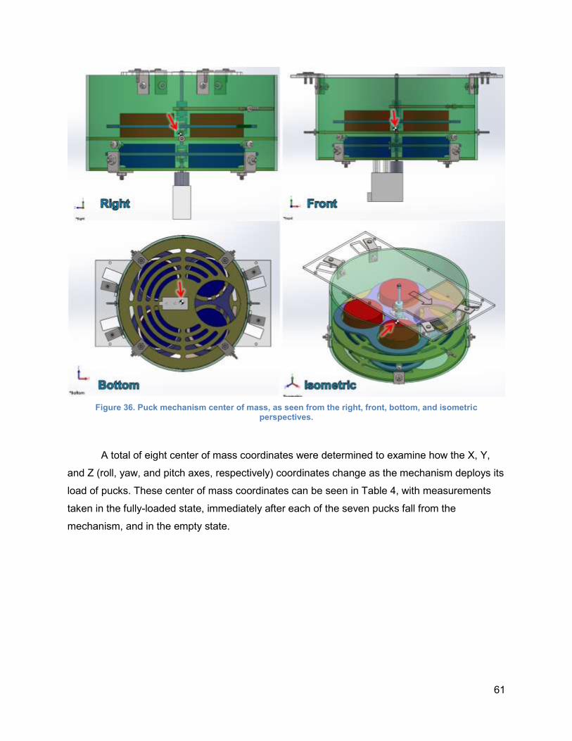
61
Figure 36. Puck mechanism center of mass, as seen from the right, front, bottom, and isometric perspectives.
A total of eight center of mass coordinates were determined to examine how the X, Y,
and Z (roll, yaw, and pitch axes, respectively) coordinates change as the mechanism deploys its
load of pucks. These center of mass coordinates can be seen in Table 4, with measurements
taken in the fully-loaded state, immediately after each of the seven pucks fall from the
mechanism, and in the empty state.
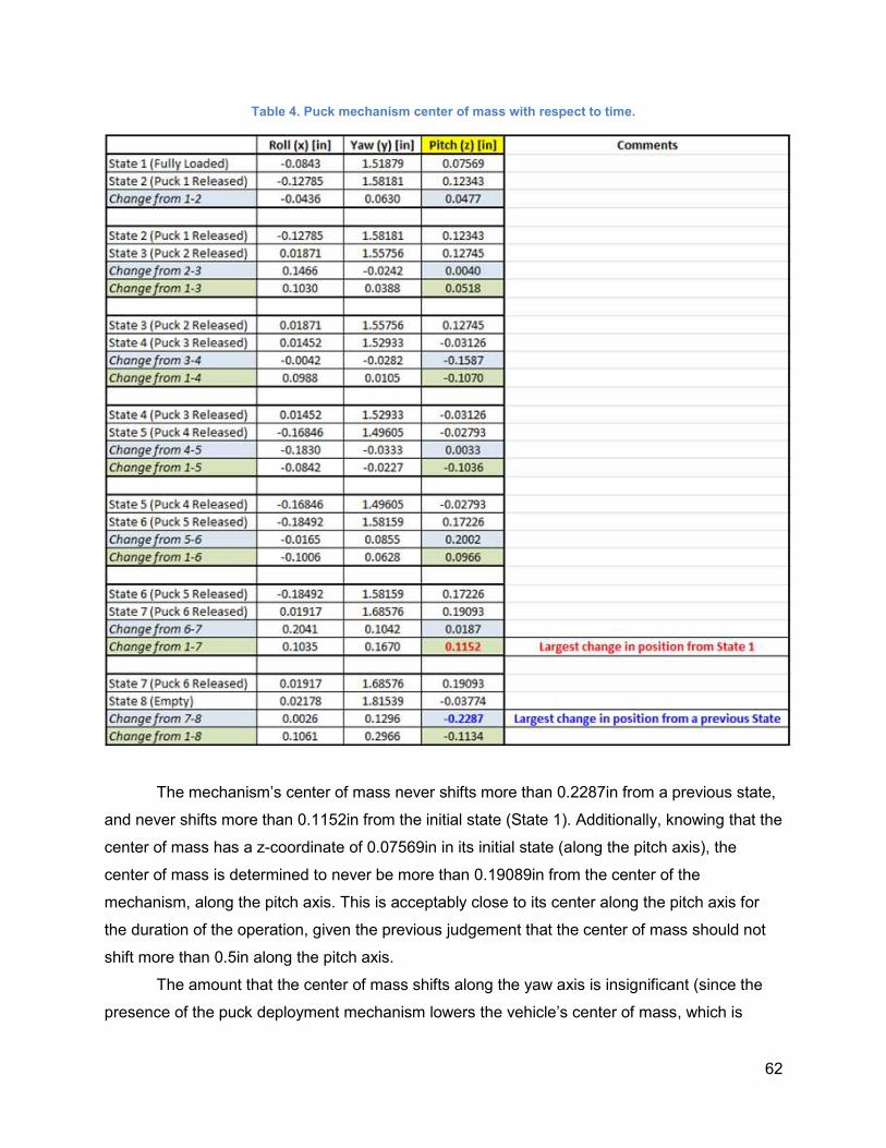
62
Table 4. Puck mechanism center of mass with respect to time.
The mechanism’s center of mass never shifts more than 0.2287in from a previous state,
and never shifts more than 0.1152in from the initial state (State 1). Additionally, knowing that the
center of mass has a z-coordinate of 0.07569in in its initial state (along the pitch axis), the
center of mass is determined to never be more than 0.19089in from the center of the
mechanism, along the pitch axis. This is acceptably close to its center along the pitch axis for
the duration of the operation, given the previous judgement that the center of mass should not
shift more than 0.5in along the pitch axis.
The amount that the center of mass shifts along the yaw axis is insignificant (since the
presence of the puck deployment mechanism lowers the vehicle’s center of mass, which is
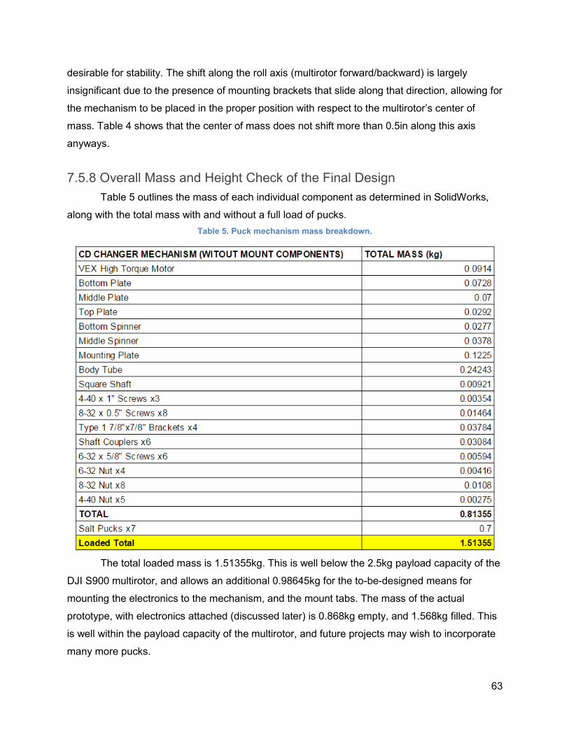
63
desirable for stability. The shift along the roll axis (multirotor forward/backward) is largely
insignificant due to the presence of mounting brackets that slide along that direction, allowing for
the mechanism to be placed in the proper position with respect to the multirotor’s center of
mass. Table 4 shows that the center of mass does not shift more than 0.5in along this axis
anyways.
7.5.8 Overall Mass and Height Check of the Final Design
Table 5 outlines the mass of each individual component as determined in SolidWorks,
along with the total mass with and without a full load of pucks.
Table 5. Puck mechanism mass breakdown.
The total loaded mass is 1.51355kg. This is well below the 2.5kg payload capacity of the
DJI S900 multirotor, and allows an additional 0.98645kg for the to-be-designed means for
mounting the electronics to the mechanism, and the mount tabs. The mass of the actual
prototype, with electronics attached (discussed later) is 0.868kg empty, and 1.568kg filled. This
is well within the payload capacity of the multirotor, and future projects may wish to incorporate
many more pucks.
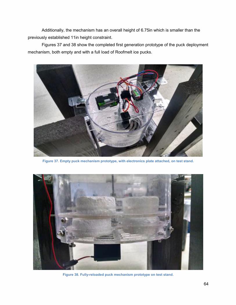
64
Additionally, the mechanism has an overall height of 6.75in which is smaller than the
previously established 11in height constraint.
Figures 37 and 38 show the completed first generation prototype of the puck deployment
mechanism, both empty and with a full load of Roofmelt ice pucks.
Figure 37. Empty puck mechanism prototype, with electronics plate attached, on test stand.
Figure 38. Fully-reloaded puck mechanism prototype on test stand.
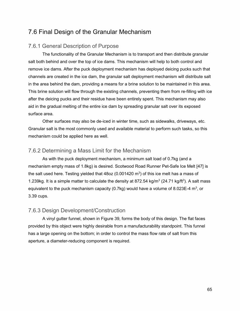
65
7.6 Final Design of the Granular Mechanism
7.6.1 General Description of Purpose
The functionality of the Granular Mechanism is to transport and then distribute granular
salt both behind and over the top of ice dams. This mechanism will help to both control and
remove ice dams. After the puck deployment mechanism has deployed deicing pucks such that
channels are created in the ice dam, the granular salt deployment mechanism will distribute salt
in the area behind the dam, providing a means for a brine solution to be maintained in this area.
This brine solution will flow through the existing channels, preventing them from re-filling with ice
after the deicing pucks and their residue have been entirely spent. This mechanism may also
aid in the gradual melting of the entire ice dam by spreading granular salt over its exposed
surface area.
Other surfaces may also be de-iced in winter time, such as sidewalks, driveways, etc.
Granular salt is the most commonly used and available material to perform such tasks, so this
mechanism could be applied here as well.
7.6.2 Determining a Mass Limit for the Mechanism
As with the puck deployment mechanism, a minimum salt load of 0.7kg (and a
mechanism empty mass of 1.8kg) is desired. Scotwood Road Runner Pet-Safe Ice Melt [47] is
the salt used here. Testing yielded that 48oz (0.001420 m3) of this ice melt has a mass of
1.239kg. It is a simple matter to calculate the density at 872.54 kg/m3 (24.71 kg/ft3). A salt mass
equivalent to the puck mechanism capacity (0.7kg) would have a volume of 8.023E-4 m3, or
3.39 cups.
7.6.3 Design Development/Construction
A vinyl gutter funnel, shown in Figure 39, forms the body of this design. The flat faces
provided by this object were highly desirable from a manufacturability standpoint. This funnel
has a large opening on the bottom; in order to control the mass flow rate of salt from this
aperture, a diameter-reducing component is required.
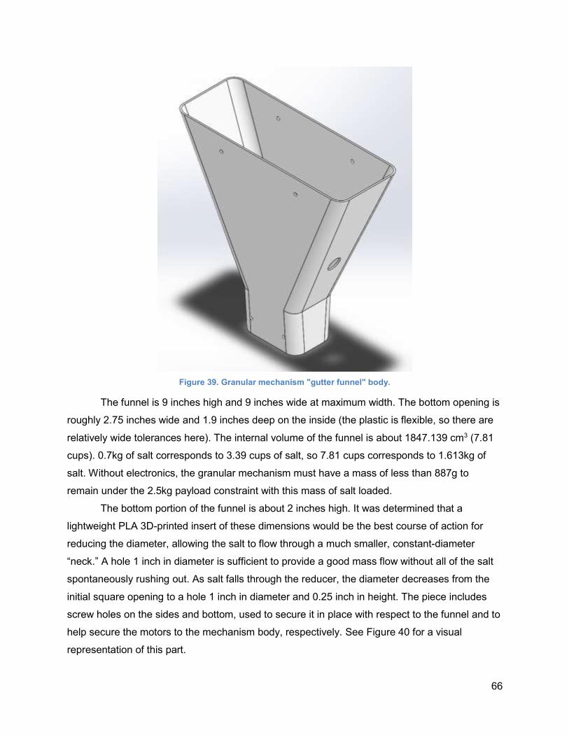
66
Figure 39. Granular mechanism "gutter funnel" body.
The funnel is 9 inches high and 9 inches wide at maximum width. The bottom opening is
roughly 2.75 inches wide and 1.9 inches deep on the inside (the plastic is flexible, so there are
relatively wide tolerances here). The internal volume of the funnel is about 1847.139 cm3 (7.81
cups). 0.7kg of salt corresponds to 3.39 cups of salt, so 7.81 cups corresponds to 1.613kg of
salt. Without electronics, the granular mechanism must have a mass of less than 887g to
remain under the 2.5kg payload constraint with this mass of salt loaded.
The bottom portion of the funnel is about 2 inches high. It was determined that a
lightweight PLA 3D-printed insert of these dimensions would be the best course of action for
reducing the diameter, allowing the salt to flow through a much smaller, constant-diameter
“neck.” A hole 1 inch in diameter is sufficient to provide a good mass flow without all of the salt
spontaneously rushing out. As salt falls through the reducer, the diameter decreases from the
initial square opening to a hole 1 inch in diameter and 0.25 inch in height. The piece includes
screw holes on the sides and bottom, used to secure it in place with respect to the funnel and to
help secure the motors to the mechanism body, respectively. See Figure 40 for a visual
representation of this part.
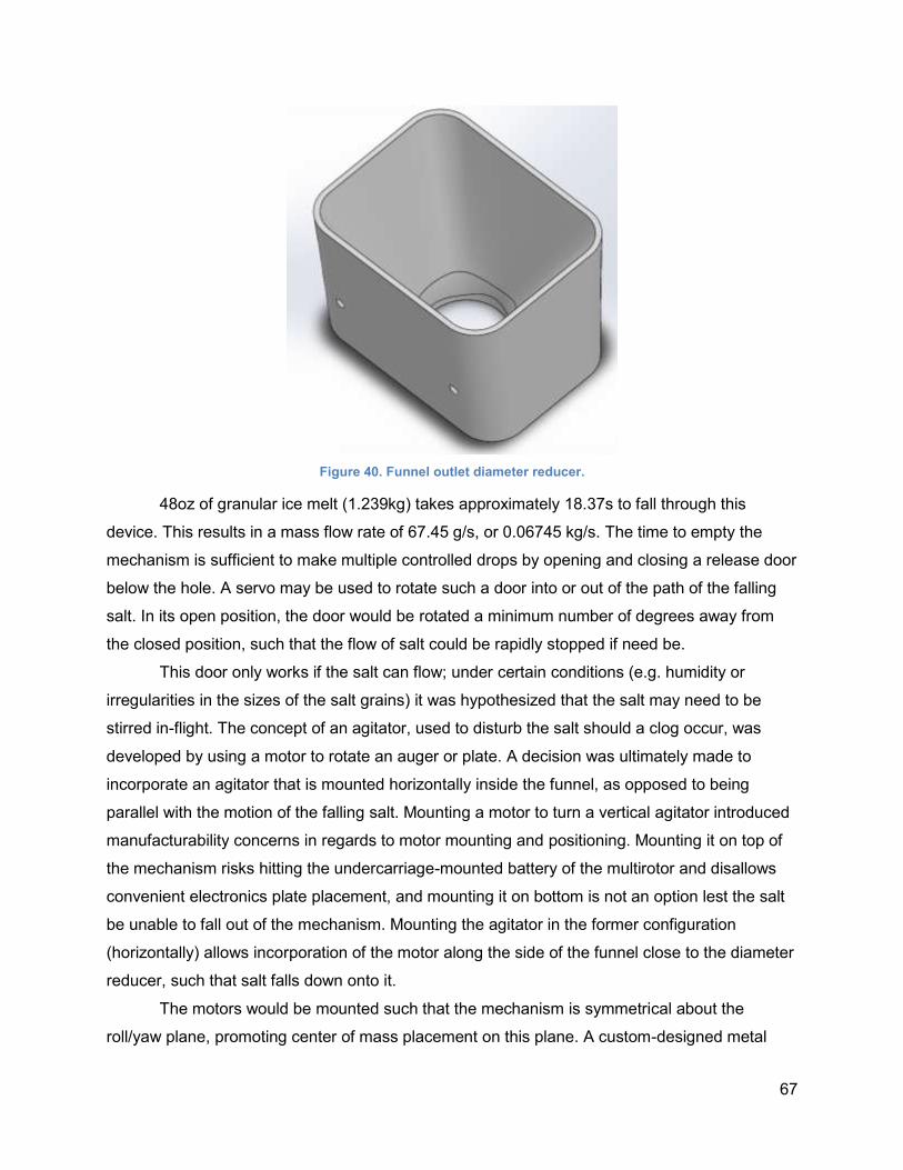
67
Figure 40. Funnel outlet diameter reducer.
48oz of granular ice melt (1.239kg) takes approximately 18.37s to fall through this
device. This results in a mass flow rate of 67.45 g/s, or 0.06745 kg/s. The time to empty the
mechanism is sufficient to make multiple controlled drops by opening and closing a release door
below the hole. A servo may be used to rotate such a door into or out of the path of the falling
salt. In its open position, the door would be rotated a minimum number of degrees away from
the closed position, such that the flow of salt could be rapidly stopped if need be.
This door only works if the salt can flow; under certain conditions (e.g. humidity or
irregularities in the sizes of the salt grains) it was hypothesized that the salt may need to be
stirred in-flight. The concept of an agitator, used to disturb the salt should a clog occur, was
developed by using a motor to rotate an auger or plate. A decision was ultimately made to
incorporate an agitator that is mounted horizontally inside the funnel, as opposed to being
parallel with the motion of the falling salt. Mounting a motor to turn a vertical agitator introduced
manufacturability concerns in regards to motor mounting and positioning. Mounting it on top of
the mechanism risks hitting the undercarriage-mounted battery of the multirotor and disallows
convenient electronics plate placement, and mounting it on bottom is not an option lest the salt
be unable to fall out of the mechanism. Mounting the agitator in the former configuration
(horizontally) allows incorporation of the motor along the side of the funnel close to the diameter
reducer, such that salt falls down onto it.
The motors would be mounted such that the mechanism is symmetrical about the
roll/yaw plane, promoting center of mass placement on this plane. A custom-designed metal
68
frame using 3003 formable aluminum could be used to secure the motors next to the sloped
surface of the funnel. The frame would be bent to shape, allowing the bottom of the frame to be
screwed into the bottom of the 3D-printed flow limiter, and the top of the frame to be screwed
into the bottom of the rectangular mounting plate. Ultimately, this frame would resemble a
“handle” coming off one side of the funnel. The swivel door servo would mount directly into the
bottom section of the frame, and the agitator motor would be mounted to the middle portion of
the frame using additional pieces of formable aluminum.
An exploded view of the final granular mechanism assembly can be seen below in
Figure 41. Each of the critical parts is numbered in the exploded view. The corresponding name
for each numbered part is as follows:
1. Mounting Plate
2. Gutter Funnel
3. Funnel Outlet Reducer
4. Swivel Release Door
5. Swivel Release Door Hub
6. Swivel Release Door Shaft
7. VEX 269 Motor
8. Agitator
9. Agitator Shaft
10. VEX Servo
11. Nylon Sleeve
12. Double Sealed Bearing
13. Frame Piece 1
14. Frame Piece 2
15. Frame Piece 3
16. Frame Piece 4
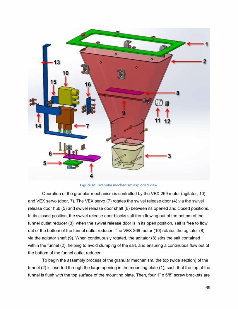
69
Figure 41. Granular mechanism exploded view.
Operation of the granular mechanism is controlled by the VEX 269 motor (agitator, 10)
and VEX servo (door, 7). The VEX servo (7) rotates the swivel release door (4) via the swivel
release door hub (5) and swivel release door shaft (6) between its opened and closed positions.
In its closed position, the swivel release door blocks salt from flowing out of the bottom of the
funnel outlet reducer (3); when the swivel release door is in its open position, salt is free to flow
out of the bottom of the funnel outlet reducer. The VEX 269 motor (10) rotates the agitator (8)
via the agitator shaft (9). When continuously rotated, the agitator (8) stirs the salt contained
within the funnel (2), helping to avoid clumping of the salt, and ensuring a continuous flow out of
the bottom of the funnel outlet reducer.
To begin the assembly process of the granular mechanism, the top (wide section) of the
funnel (2) is inserted through the large opening in the mounting plate (1), such that the top of the
funnel is flush with the top surface of the mounting plate. Then, four 1” x 5/8” screw brackets are
70
used to secure the funnel and mount plate to each other with 8-32 x 3/8in screws and hex nuts.
Next, the funnel outlet reducer (3) is inserted through the top of the funnel and pressed down
through the funnel’s square-shaped tapering outlet, such that the bottom of the reducer is flush
with the bottom surface of the funnel. It is critical that the two screw holes on the bottom of the
funnel outlet reducer are positioned on the motor-side of the funnel as seen in the left side of
Figure 41, to allow fastener connection. Four 6-32 x 3/4in screws are then used to attach the
funnel and funnel outlet reducer, keeping the reducer securely in position.
Next, the VEX Servo (10) is attached to frame piece 1 (13) with two 6-32 x 3/4in screws.
Two 1/4in #6-clearance spacers are needed between frame piece 1 (13) and the screw mounts
in the VEX Servo to ensure that the servo’s rotating piece does not come in direct contact with
the frame. Frame pieces 2 and 3 (14 and 15) are attached to frame piece 1 (13) via 6-32 x 3/8in
screws and nuts. Frame piece 4 (16) is then attached to frame pieces 2 and 3 (14 and 15) via 6-
32 x 3/8in screws and nuts. Together, these four frame pieces comprise the “motor frame”.
Next, the VEX 269 motor (7) is mounted to frame piece 4 (16) using two 6-32 x 3/8in screws.
After the VEX Servo and VEX 269 motor have been mounted to the motor frame, the frame
piece 1 - and everything attached to it - is mounted to the left side of the mounting plate (1) and
to the bottom of the funnel outlet reducer (3).
Next, the double sealed bearing (12) is hand press-fit into the nylon sleeve (11), and the
nylon sleeve is glued into its respective hole-cutout in the funnel (2) using JB Weld. Then,
holding a 3/16in-ID shaft collar inside of the funnel behind the nylon sleeve, the agitator shaft (9)
is passed through the double sealed bearing (12), collar, and its clearance hole on the other
side of the funnel, finally entering into the clutch of the VEX 269 motor (7). The collar is
tightened to the agitator shaft (9) via a set screw to ensure that the agitator shaft does not come
loose. Next, the agitator (8) is glued to the shaft using JB Weld, centered lengthwise along the
exposed area of the shaft.
The swivel release door hub (5) is connected to the swivel release door (4) using 6-32 x
3/8in screws and nuts. Then, the swivel release door shaft (6) is passed through the swivel
release door hub and swivel release door. Three #10 PTFE washers are placed on the swivel
release door shaft, coming to rest on the surface of the swivel release door. This comprises the
“swivel release door assembly.” Next, a #10 PTFE washer, followed by a 3/16in-ID shaft collar,
is placed on frame piece 1 (13) directly below the clutch of the VEX servo (10). The swivel
release door assembly is then installed by passing the swivel release door shaft through frame
piece 1, the #10 PTFE washer, and the 3/16in-ID shaft collar before finally entering the servo
clutch. The collar closest to the VEX servo’s clutch is tightened to the swivel release door shaft
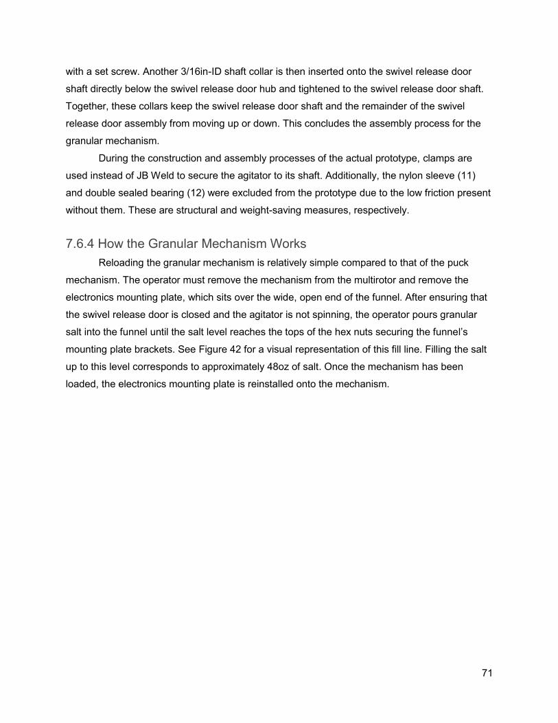
71
with a set screw. Another 3/16in-ID shaft collar is then inserted onto the swivel release door
shaft directly below the swivel release door hub and tightened to the swivel release door shaft.
Together, these collars keep the swivel release door shaft and the remainder of the swivel
release door assembly from moving up or down. This concludes the assembly process for the
granular mechanism.
During the construction and assembly processes of the actual prototype, clamps are
used instead of JB Weld to secure the agitator to its shaft. Additionally, the nylon sleeve (11)
and double sealed bearing (12) were excluded from the prototype due to the low friction present
without them. These are structural and weight-saving measures, respectively.
7.6.4 How the Granular Mechanism Works
Reloading the granular mechanism is relatively simple compared to that of the puck
mechanism. The operator must remove the mechanism from the multirotor and remove the
electronics mounting plate, which sits over the wide, open end of the funnel. After ensuring that
the swivel release door is closed and the agitator is not spinning, the operator pours granular
salt into the funnel until the salt level reaches the tops of the hex nuts securing the funnel’s
mounting plate brackets. See Figure 42 for a visual representation of this fill line. Filling the salt
up to this level corresponds to approximately 48oz of salt. Once the mechanism has been
loaded, the electronics mounting plate is reinstalled onto the mechanism.
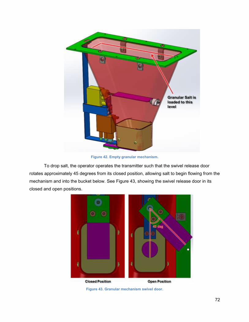
72
Figure 42. Empty granular mechanism.
To drop salt, the operator operates the transmitter such that the swivel release door
rotates approximately 45 degrees from its closed position, allowing salt to begin flowing from the
mechanism and into the bucket below. See Figure 43, showing the swivel release door in its
closed and open positions.
Figure 43. Granular mechanism swivel door.
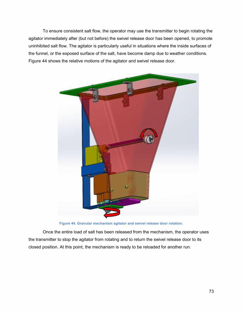
73
To ensure consistent salt flow, the operator may use the transmitter to begin rotating the
agitator immediately after (but not before) the swivel release door has been opened, to promote
uninhibited salt flow. The agitator is particularly useful in situations where the inside surfaces of
the funnel, or the exposed surface of the salt, have become damp due to weather conditions.
Figure 44 shows the relative motions of the agitator and swivel release door.
Figure 44. Granular mechanism agitator and swivel release door rotation.
Once the entire load of salt has been released from the mechanism, the operator uses
the transmitter to stop the agitator from rotating and to return the swivel release door to its
closed position. At this point, the mechanism is ready to be reloaded for another run.
74
7.6.5 Customization of the Mounting Plate
The customization of the mounting plate for the granular mechanism was largely
established in Section 7.6.3. As discussed, the mounting plate has a large cutout in its center to
fit the top portion of the funnel. This large cutout also serves as means for filling the funnel with
granular salt. Unlike the puck mechanism, the granular mechanism does not need to be
disassembled from the mounting plate to be refilled; rather, it is necessary only for the
mechanism to be detached from the multirotor, and the electronics plate to be temporarily
moved. The mounting plate can be considered permanently attached to the mechanism, seeing
as it serves as a common connection point for the frame and funnel.
Additional screw clearance holes would be added to the mounting plate to allow for
mounting of the aluminum frame via screws, as well as for the installation of brackets to more
rigidly connect the funnel and mounting plate. Ultimately, these modifications brought the mass
of the granular mechanism mounting plate down to 0.05877kg.
7.6.6 Finite Element Analysis of the Rectangular Mounting Plate
The granular mechanism’s rectangular mounting plate has more material cut away than
the puck mechanism’s plate, compared to the generic plate template used by both mechanisms.
Therefore, a Finite Element Analysis was performed on the granular mechanism’s mounting
plate to ensure that the 0.125in material thickness of the acrylic mounting plate would be
sufficient for supporting the maximum possible 2.5kg mechanism mass. This mass was
distributed over a 2in long region in the middle of each side of the mounting plate, under the
assumption that this would create large stresses within the part.
In the SolidWorks simulation, the mounting plate was fixtured in its four corners where it
comes in contact with each of the mounting units, as well as at the locations where it is
supported by the four funnel-mounting plate brackets (where little bending occurs). An
equivalent force of 24.525N was applied over the previously described regions of the mounting
plate, distributing one half of the force (12.2625N) to each side in the corresponding area. In
Figures 45 and 46, the top view shows the fixtured areas, and the bottom view shows the areas
where the forces were applied.
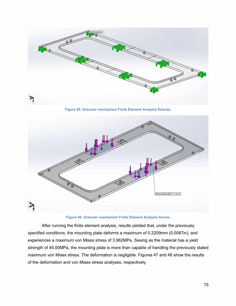
75
Figure 45. Granular mechanism Finite Element Analysis fixtures.
Figure 46. Granular mechanism Finite Element Analysis forces.
After running the finite element analysis, results yielded that, under the previously
specified conditions, the mounting plate deforms a maximum of 0.2209mm (0.0087in), and
experiences a maximum von Mises stress of 3.962MPa. Seeing as the material has a yield
strength of 45.00MPa, the mounting plate is more than capable of handling the previously stated
maximum von Mises stress. The deformation is negligible. Figures 47 and 48 show the results
of the deformation and von Mises stress analyses, respectively.
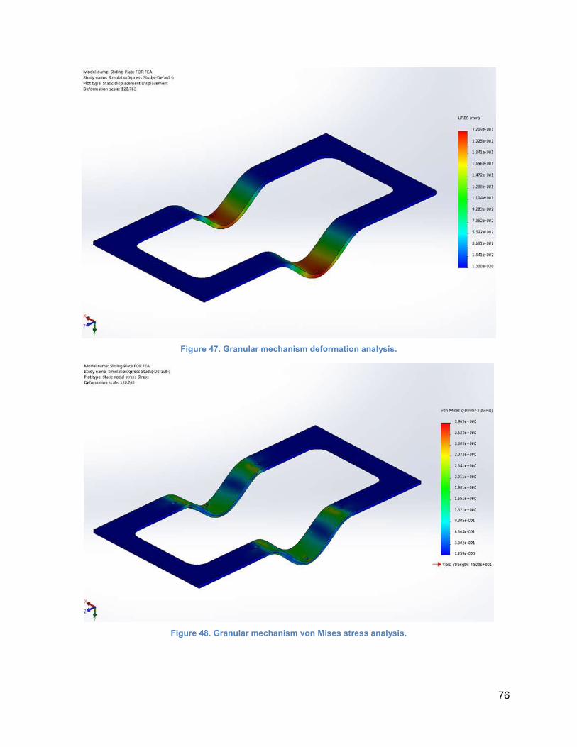
76
Figure 47. Granular mechanism deformation analysis.
Figure 48. Granular mechanism von Mises stress analysis.
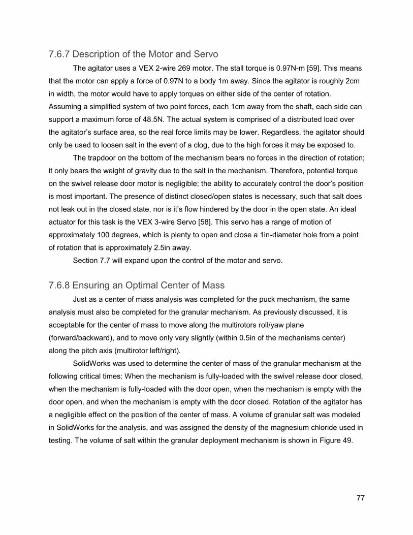
77
7.6.7 Description of the Motor and Servo
The agitator uses a VEX 2-wire 269 motor. The stall torque is 0.97N-m [59]. This means
that the motor can apply a force of 0.97N to a body 1m away. Since the agitator is roughly 2cm
in width, the motor would have to apply torques on either side of the center of rotation.
Assuming a simplified system of two point forces, each 1cm away from the shaft, each side can
support a maximum force of 48.5N. The actual system is comprised of a distributed load over
the agitator’s surface area, so the real force limits may be lower. Regardless, the agitator should
only be used to loosen salt in the event of a clog, due to the high forces it may be exposed to.
The trapdoor on the bottom of the mechanism bears no forces in the direction of rotation;
it only bears the weight of gravity due to the salt in the mechanism. Therefore, potential torque
on the swivel release door motor is negligible; the ability to accurately control the door’s position
is most important. The presence of distinct closed/open states is necessary, such that salt does
not leak out in the closed state, nor is it’s flow hindered by the door in the open state. An ideal
actuator for this task is the VEX 3-wire Servo [58]. This servo has a range of motion of
approximately 100 degrees, which is plenty to open and close a 1in-diameter hole from a point
of rotation that is approximately 2.5in away.
Section 7.7 will expand upon the control of the motor and servo.
7.6.8 Ensuring an Optimal Center of Mass
Just as a center of mass analysis was completed for the puck mechanism, the same
analysis must also be completed for the granular mechanism. As previously discussed, it is
acceptable for the center of mass to move along the multirotors roll/yaw plane
(forward/backward), and to move only very slightly (within 0.5in of the mechanisms center)
along the pitch axis (multirotor left/right).
SolidWorks was used to determine the center of mass of the granular mechanism at the
following critical times: When the mechanism is fully-loaded with the swivel release door closed,
when the mechanism is fully-loaded with the door open, when the mechanism is empty with the
door open, and when the mechanism is empty with the door closed. Rotation of the agitator has
a negligible effect on the position of the center of mass. A volume of granular salt was modeled
in SolidWorks for the analysis, and was assigned the density of the magnesium chloride used in
testing. The volume of salt within the granular deployment mechanism is shown in Figure 49.
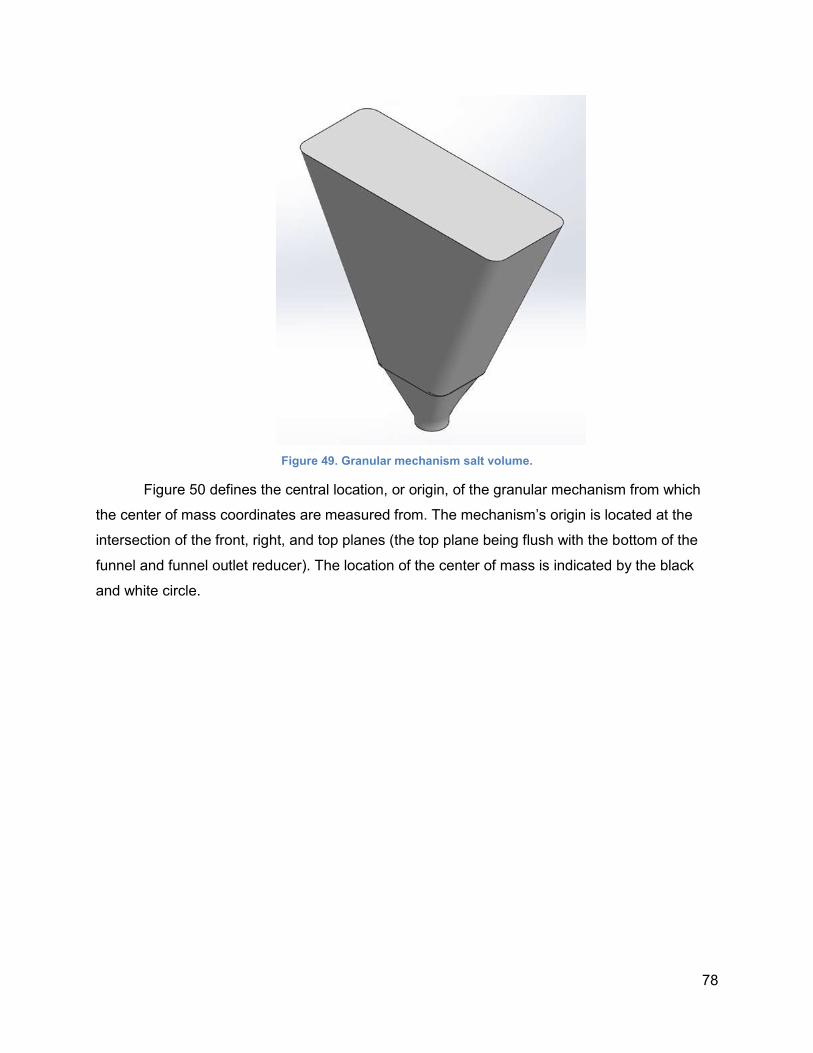
78
Figure 49. Granular mechanism salt volume.
Figure 50 defines the central location, or origin, of the granular mechanism from which
the center of mass coordinates are measured from. The mechanism’s origin is located at the
intersection of the front, right, and top planes (the top plane being flush with the bottom of the
funnel and funnel outlet reducer). The location of the center of mass is indicated by the black
and white circle.
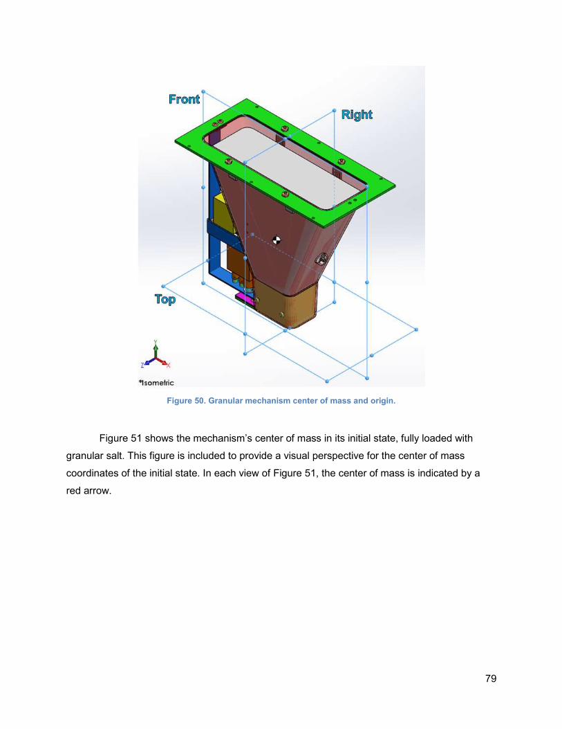
79
Figure 50. Granular mechanism center of mass and origin.
Figure 51 shows the mechanism’s center of mass in its initial state, fully loaded with
granular salt. This figure is included to provide a visual perspective for the center of mass
coordinates of the initial state. In each view of Figure 51, the center of mass is indicated by a
red arrow.
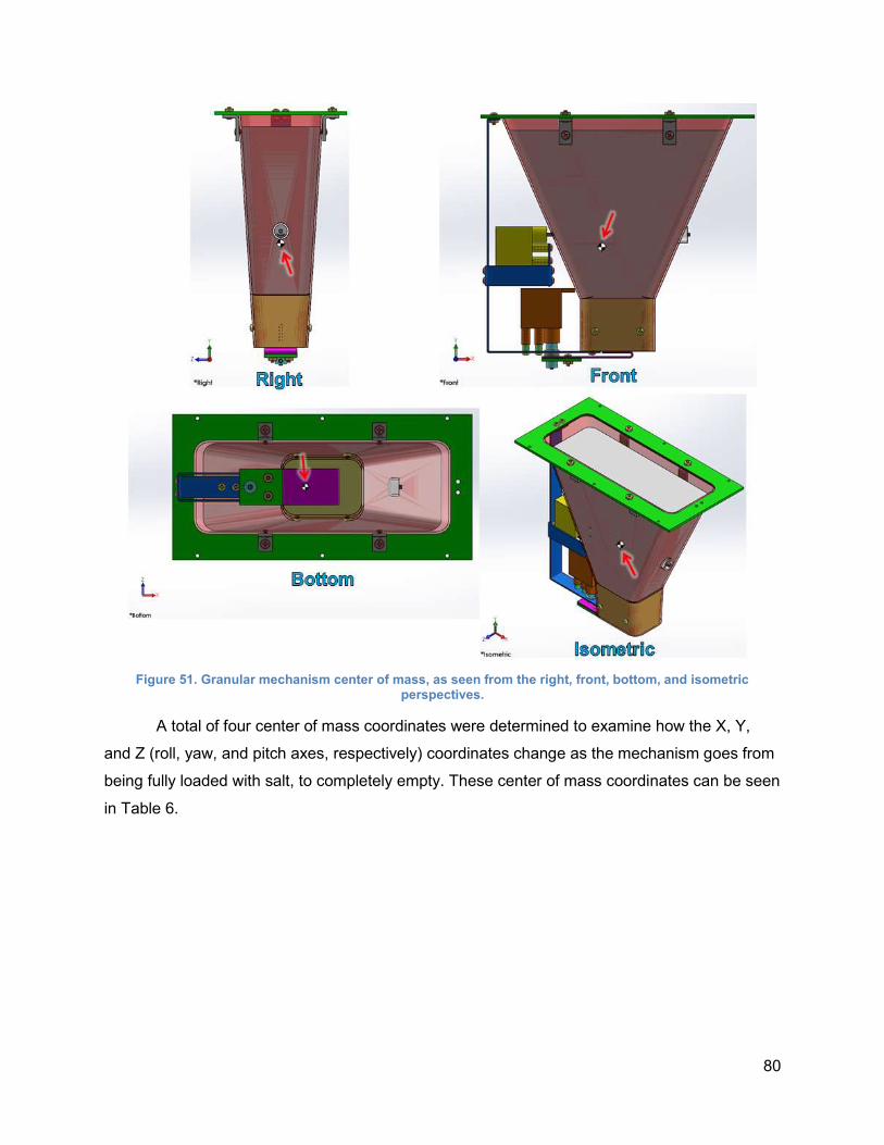
80
Figure 51. Granular mechanism center of mass, as seen from the right, front, bottom, and isometric perspectives.
A total of four center of mass coordinates were determined to examine how the X, Y,
and Z (roll, yaw, and pitch axes, respectively) coordinates change as the mechanism goes from
being fully loaded with salt, to completely empty. These center of mass coordinates can be seen
in Table 6.
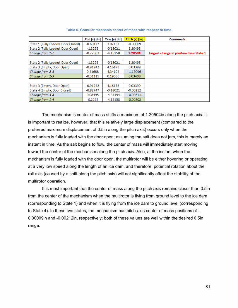
81
Table 6. Granular mechanis center of mass with respect to time.
The mechanism’s center of mass shifts a maximum of 1.20504in along the pitch axis. It
is important to realize, however, that this relatively large displacement (compared to the
preferred maximum displacement of 0.5in along the pitch axis) occurs only when the
mechanism is fully loaded with the door open; assuming the salt does not jam, this is merely an
instant in time. As the salt begins to flow, the center of mass will immediately start moving
toward the center of the mechanism along the pitch axis. Also, at the instant when the
mechanism is fully loaded with the door open, the multirotor will be either hovering or operating
at a very low speed along the length of an ice dam, and therefore, potential rotation about the
roll axis (caused by a shift along the pitch axis) will not significantly affect the stability of the
multirotor operation.
It is most important that the center of mass along the pitch axis remains closer than 0.5in
from the center of the mechanism when the multirotor is flying from ground level to the ice dam
(corresponding to State 1) and when it is flying from the ice dam to ground level (corresponding
to State 4). In these two states, the mechanism has pitch-axis center of mass positions of -
0.00009in and -0.00212in, respectively; both of these values are well within the desired 0.5in
range.
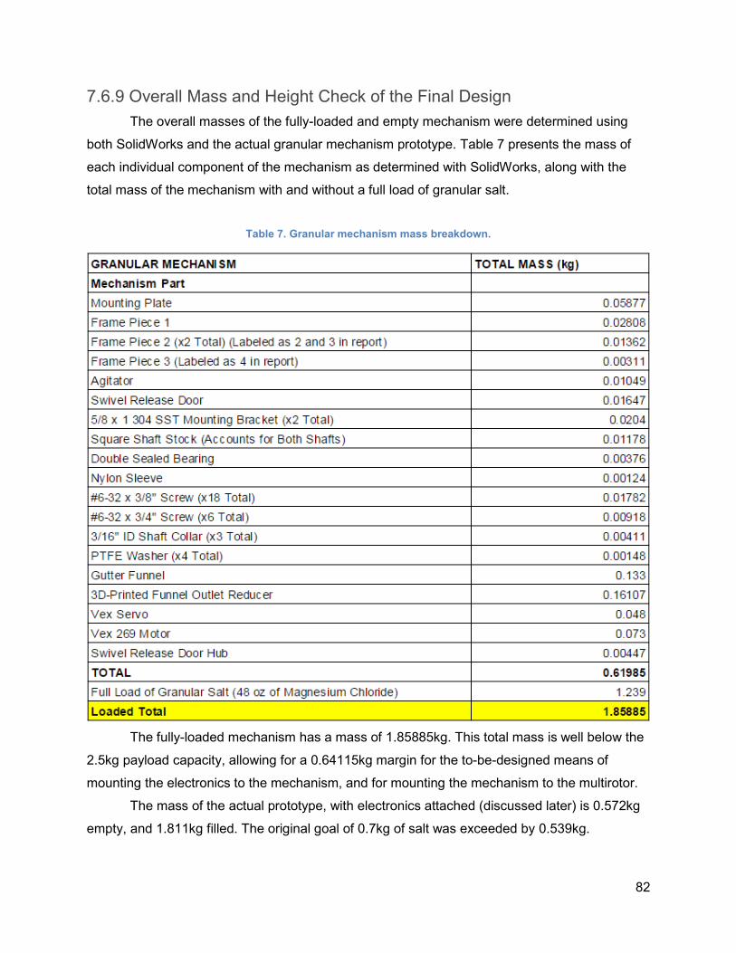
82
7.6.9 Overall Mass and Height Check of the Final Design
The overall masses of the fully-loaded and empty mechanism were determined using
both SolidWorks and the actual granular mechanism prototype. Table 7 presents the mass of
each individual component of the mechanism as determined with SolidWorks, along with the
total mass of the mechanism with and without a full load of granular salt.
Table 7. Granular mechanism mass breakdown.
The fully-loaded mechanism has a mass of 1.85885kg. This total mass is well below the
2.5kg payload capacity, allowing for a 0.64115kg margin for the to-be-designed means of
mounting the electronics to the mechanism, and for mounting the mechanism to the multirotor.
The mass of the actual prototype, with electronics attached (discussed later) is 0.572kg
empty, and 1.811kg filled. The original goal of 0.7kg of salt was exceeded by 0.539kg.
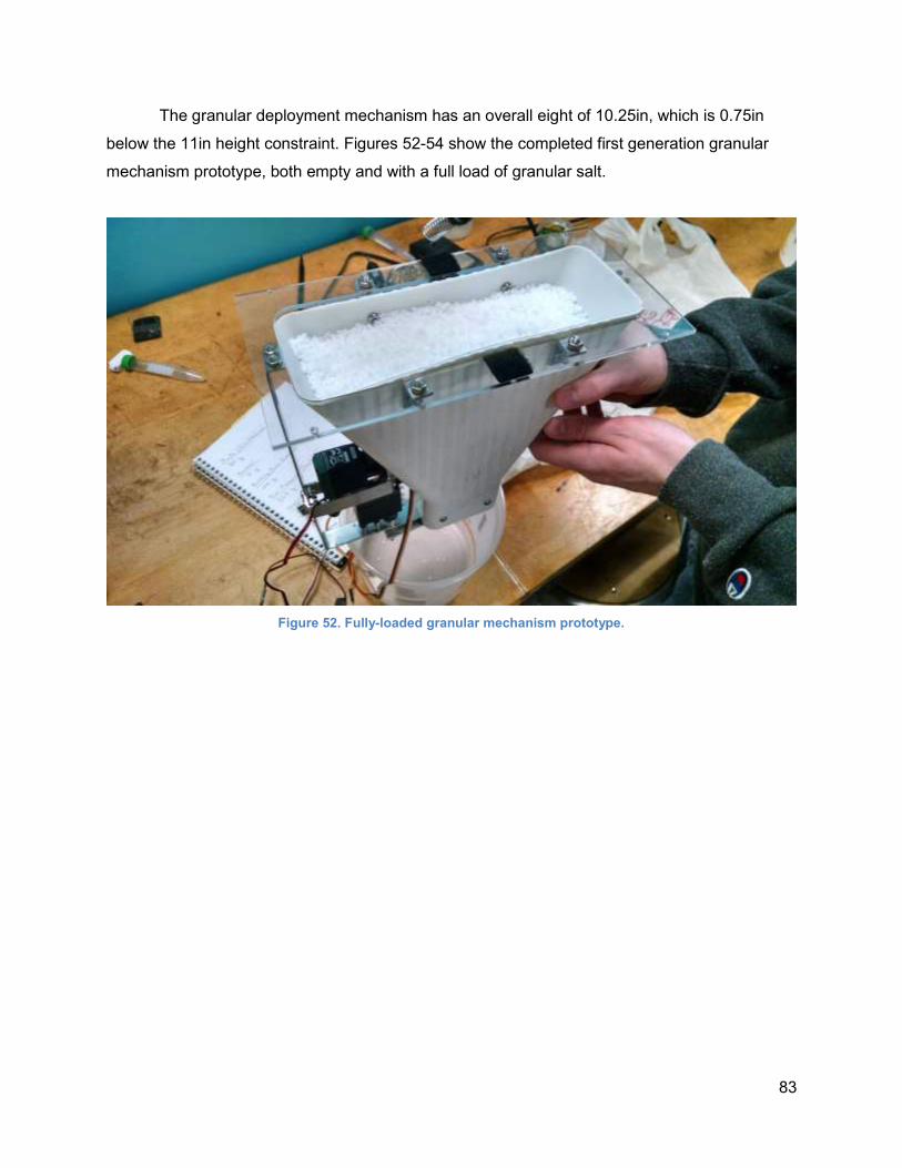
83
The granular deployment mechanism has an overall eight of 10.25in, which is 0.75in
below the 11in height constraint. Figures 52-54 show the completed first generation granular
mechanism prototype, both empty and with a full load of granular salt.
Figure 52. Fully-loaded granular mechanism prototype.
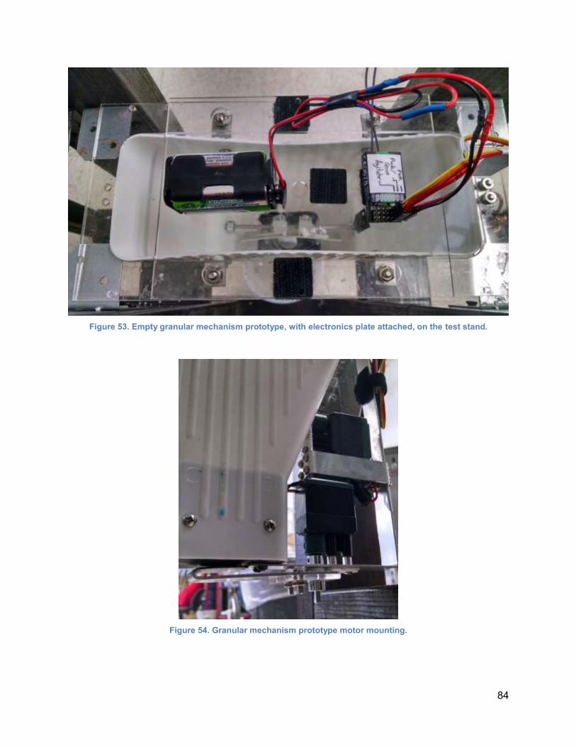
84
Figure 53. Empty granular mechanism prototype, with electronics plate attached, on the test stand.
Figure 54. Granular mechanism prototype motor mounting.
85
7.7 Electronics and Control
7.7.1 Electronics Overview
The only necessary electronics needed to drive the mechanisms’ motors are a battery
pack and a receiver with enough free channels to power a maximum of two motors (the granular
mechanism has two motors, while the puck mechanism has only one; only one mechanism is
mounted at a time). It is recommended that future projects incorporate the electronics package
and the mechanism mounts into one static package. Lack of regular physical access to the
multirotor resulted in the simpler-to-design arrangement described here.
The easiest way to mount the electronics plate to the puck mechanism and funnel
mechanism mount plates was determined to be small squares of adhesive-backed hook-and-
loop fastener. The receiver and battery pack are affixed to this plate with hook-and-loop fastener
as well, to aid in battery recharging efforts. Originally, the intent was to affix the electronics plate
to the mount plates with clevis pins. However, hook-and-loop is faster to remove/replace when
reloading either mechanism.
Inclusion of a camera system with this electronics package would allow for relative
precision in the dropping of the salt from each mechanism; due to constraints alluded to earlier
with regards to multirotor access, line-of-sight must be used instead. Appendix A includes the
camera equipment that would have been incorporated.
The Robotics Engineering MQP, using the DJI S1000+, is known to be using a 5.8GHz
transmitter/receiver combination for flight control. With this in mind, a 2.4GHz separate
transmitter/receiver combination is used for the salt deployment system in order to reduce the
probability of interference, while simultaneously allowing control over the mechanisms
independent of the flight controls. The Flysky FS-iA6 [60] with a paired 6-channel receiver is
ideal for this application. The electronics package and transmitter are pictured in Figure 55.
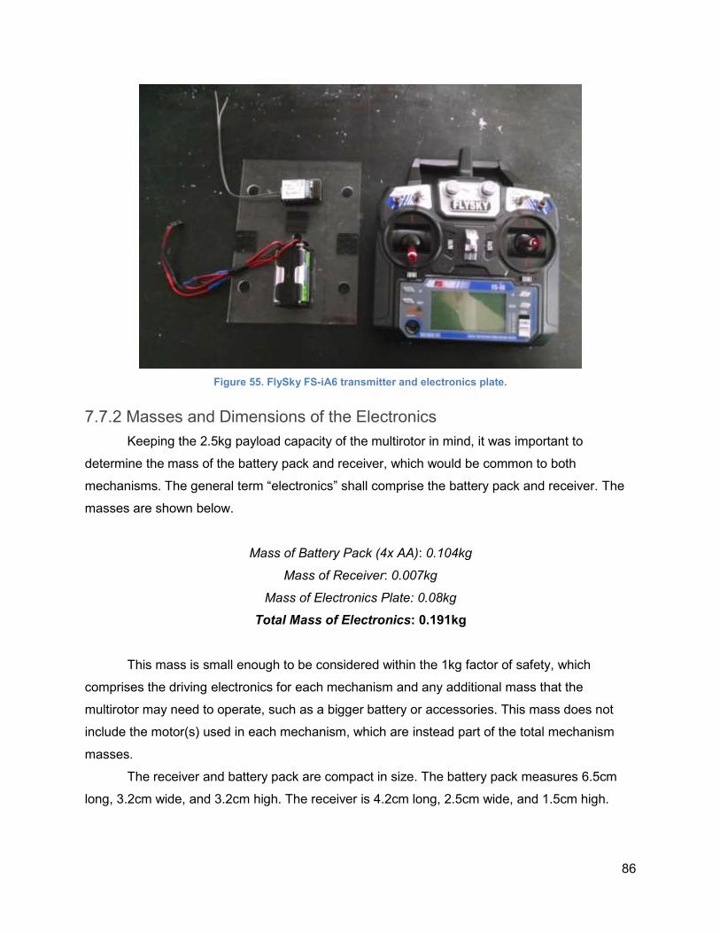
86
Figure 55. FlySky FS-iA6 transmitter and electronics plate.
7.7.2 Masses and Dimensions of the Electronics
Keeping the 2.5kg payload capacity of the multirotor in mind, it was important to
determine the mass of the battery pack and receiver, which would be common to both
mechanisms. The general term “electronics” shall comprise the battery pack and receiver. The
masses are shown below.
Mass of Battery Pack (4x AA): 0.104kg
Mass of Receiver: 0.007kg
Mass of Electronics Plate: 0.08kg
Total Mass of Electronics: 0.191kg
This mass is small enough to be considered within the 1kg factor of safety, which
comprises the driving electronics for each mechanism and any additional mass that the
multirotor may need to operate, such as a bigger battery or accessories. This mass does not
include the motor(s) used in each mechanism, which are instead part of the total mechanism
masses.
The receiver and battery pack are compact in size. The battery pack measures 6.5cm
long, 3.2cm wide, and 3.2cm high. The receiver is 4.2cm long, 2.5cm wide, and 1.5cm high.
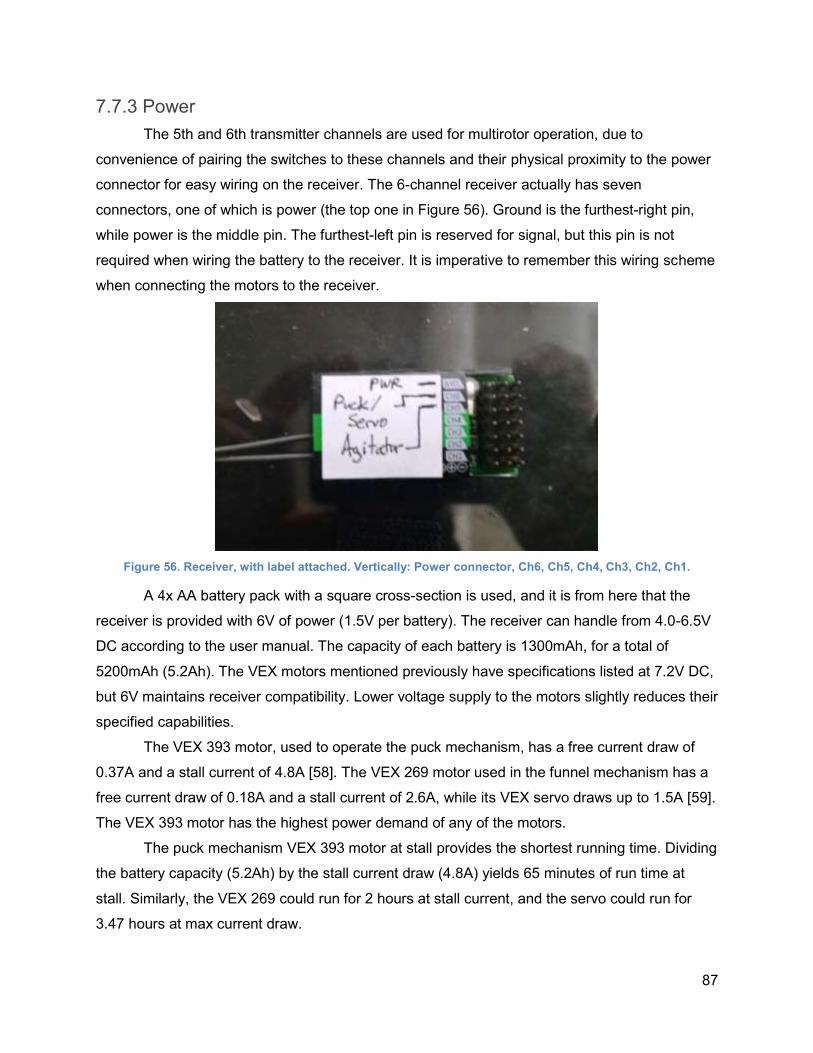
87
7.7.3 Power
The 5th and 6th transmitter channels are used for multirotor operation, due to
convenience of pairing the switches to these channels and their physical proximity to the power
connector for easy wiring on the receiver. The 6-channel receiver actually has seven
connectors, one of which is power (the top one in Figure 56). Ground is the furthest-right pin,
while power is the middle pin. The furthest-left pin is reserved for signal, but this pin is not
required when wiring the battery to the receiver. It is imperative to remember this wiring scheme
when connecting the motors to the receiver.
Figure 56. Receiver, with label attached. Vertically: Power connector, Ch6, Ch5, Ch4, Ch3, Ch2, Ch1.
A 4x AA battery pack with a square cross-section is used, and it is from here that the
receiver is provided with 6V of power (1.5V per battery). The receiver can handle from 4.0-6.5V
DC according to the user manual. The capacity of each battery is 1300mAh, for a total of
5200mAh (5.2Ah). The VEX motors mentioned previously have specifications listed at 7.2V DC,
but 6V maintains receiver compatibility. Lower voltage supply to the motors slightly reduces their
specified capabilities.
The VEX 393 motor, used to operate the puck mechanism, has a free current draw of
0.37A and a stall current of 4.8A [58]. The VEX 269 motor used in the funnel mechanism has a
free current draw of 0.18A and a stall current of 2.6A, while its VEX servo draws up to 1.5A [59].
The VEX 393 motor has the highest power demand of any of the motors.
The puck mechanism VEX 393 motor at stall provides the shortest running time. Dividing
the battery capacity (5.2Ah) by the stall current draw (4.8A) yields 65 minutes of run time at
stall. Similarly, the VEX 269 could run for 2 hours at stall current, and the servo could run for
3.47 hours at max current draw.
88
7.7.4 Description of VEX Motors
The VEX motors themselves are Direct Current. The 393 and 269 are two-wire motors,
requiring a motor controller to convert to a 3-pin arrangement of signal (white), power (orange),
and ground (black). These are connected to extension cords, in a 3-pin arrangement of signal
(yellow), power (orange), and ground (red).
Motor torque is inversely proportional to speed, and directly proportional to current draw.
A motor driven at high angular velocity provides less torque and draws less current, while a
motor that is providing torque has higher current draw and lower angular velocity.
VEX 393 and 269 Motors
Both of these models have a free speed of 100 RPM. When connected to the receiver
with a 3-pin output motor controller, these motors operate on a 0-100% proportional control; 0%
does not drive the motor, while 100% drives it full speed (100 RPM) in one direction, and values
in between drive it at a fraction of full speed. Paired with a transmitter, the channels driving
these motors can be programmed to run in forward or reverse at whatever fraction of full speed
is desired.
VEX Servo
Servos differ from motors in that they contain a potentiometer, used to help accurately
control position. In general, servos do not spin multiple revolutions. Instead, a signal provides
the impetus for the servo to hold one specific position. Hence an input of 0-100% controls at
what position the servo holds, rather than the speed it rotates (as a motor would do). The
desired position is largely dependent on the orientation of the object connected to this servo,
since the VEX servo cannot rotate through more than 100 degrees or so. One end of this motion
corresponds to 0%, while the other end corresponds to 100%.
The salt release door is mounted somewhere in the middle of the 0-100% scale. An
input causes the servo to match a different position (the open position) allowing salt to fall; a
different input causes the servo to match its starting position (the closed position).
7.7.5 Transmitter Function Mapping
The receiver has six channels plus one power input, while the transmitter has many
more inputs. Four of the channels are conventionally reserved for movement (in the case of a
multirotor, throttle up/down, yaw left/right, tilt forward/back, and tilt left/right), with the four
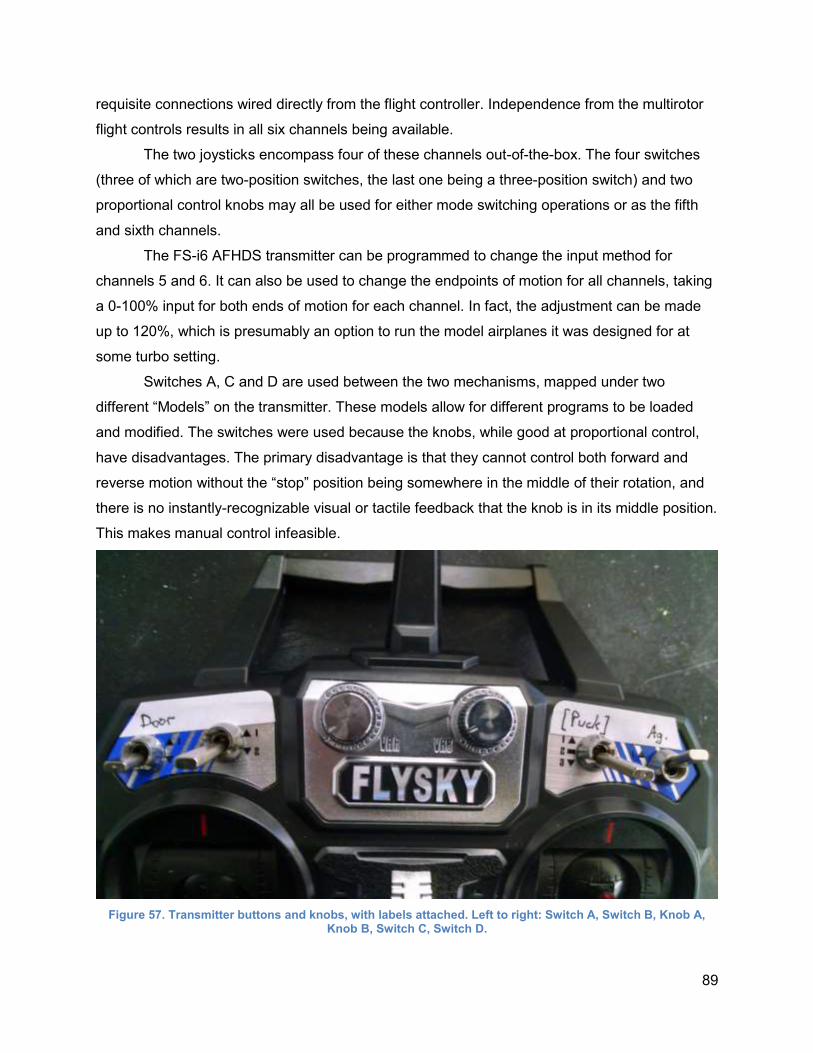
89
requisite connections wired directly from the flight controller. Independence from the multirotor
flight controls results in all six channels being available.
The two joysticks encompass four of these channels out-of-the-box. The four switches
(three of which are two-position switches, the last one being a three-position switch) and two
proportional control knobs may all be used for either mode switching operations or as the fifth
and sixth channels.
The FS-i6 AFHDS transmitter can be programmed to change the input method for
channels 5 and 6. It can also be used to change the endpoints of motion for all channels, taking
a 0-100% input for both ends of motion for each channel. In fact, the adjustment can be made
up to 120%, which is presumably an option to run the model airplanes it was designed for at
some turbo setting.
Switches A, C and D are used between the two mechanisms, mapped under two
different “Models” on the transmitter. These models allow for different programs to be loaded
and modified. The switches were used because the knobs, while good at proportional control,
have disadvantages. The primary disadvantage is that they cannot control both forward and
reverse motion without the “stop” position being somewhere in the middle of their rotation, and
there is no instantly-recognizable visual or tactile feedback that the knob is in its middle position.
This makes manual control infeasible.
Figure 57. Transmitter buttons and knobs, with labels attached. Left to right: Switch A, Switch B, Knob A, Knob B, Switch C, Switch D.
90
The MQP_PUCK model uses Channel 6, mapped to Switch C (second from the right in
Figure 57), to control the puck mechanism motor. This is the three-position switch, chosen to
allow for easier reloading operations. The Down position cycles the mechanism forward, while
the Up position cycles it backwards. This was chosen due to how the transmitter is usually held,
with one or both hands on the back of the unit. It is easier to flip the switch up to its middle
position to turn the puck motor off, than it is to pull the switch down. This method is efficient
given that the Up position is seldom used (only when reloading or when a small jam is present).
The MQP_GRAN model uses Channels 5 and 6, mapped to Switches D and A,
respectively. Switch D (Channel 5) controls the less important of the two operations for the
granular mechanism: the agitator. This device is seldom used but important in case of a clog. It
uses a two-position switch that controls the On (Down, full forward in one direction) and Off (Up)
states. Switch A (Channel 6) controls the salt release door servo. The Up position closes the
door, while the Down position opens it. Both arrangements were chosen for the same reason
discussed above for the puck mechanism: it appears easiest and quickest to flip a switch “up” to
turn off an actuator or close a door, i.e. the “Kill” conditions.
Simple labels on the transmitter, receiver, and motor wires were placed to aid in the
rapid switching of mechanisms.
7.7.6 Transmitter Programming
The transmitter is very simple to use, and comes pre-paired to its receiver out of the box.
To turn the unit on, the throttle must be in its full-down position and all switches must be in the
Up position. Most of the switch mapping was done with the latter fact in mind, with Stop being
the Up position (this is only violated by the puck mechanism, which must go in both forward and
reverse). Long-pressing the OK button near the screen on the bottom of the unit brings up the
menu. Navigating to the System Setup menu with the Up and Down keys allows selection of a
model, of which there are two: MQP_PUCK and MQP_GRAN. Long-pressing Cancel confirms
the selection, and pressing Cancel again goes back to the main menu.
The selected model may be programmed by instead navigating to the Functions Setup
menu after long-pressing the OK button. Here, channels may be “Reversed,” “End points” (0-
100% for both ends of motion) may be programmed, and “Aux. channels” may be used to set
the switches or knobs for channels 5 and 6, among other things. In all menus, OK selects an
option, Cancel goes back, and long-pressing Cancel confirms a selection.
End points are the only tricky aspects to set, in that they require significant trial-and error
to get correct; in addition, the switch or knob in question must be in the position for which

91
programming is to be accomplished. If a motor being On in the Down position is desired, the
switch must be in its Down position in order to access the ability to change its respective End
point. Similarly, it must be in its Up position to change its End point (e.g. to 0% “Stop”). From a
hardware standpoint, one must be very careful to not break the motors or mechanism while
programming the transmitter, as these motors will run while being programmed.
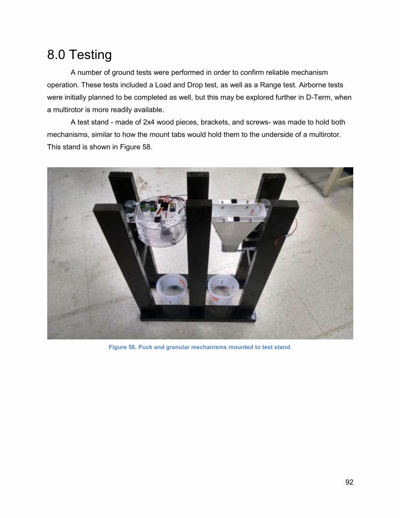
92
8.0 Testing
A number of ground tests were performed in order to confirm reliable mechanism
operation. These tests included a Load and Drop test, as well as a Range test. Airborne tests
were initially planned to be completed as well, but this may be explored further in D-Term, when
a multirotor is more readily available.
A test stand - made of 2x4 wood pieces, brackets, and screws- was made to hold both
mechanisms, similar to how the mount tabs would hold them to the underside of a multirotor.
This stand is shown in Figure 58.
Figure 58. Puck and granular mechanisms mounted to test stand.
93
8.1 Load and Drop Test
The purpose of this test is to verify that the pucks and granular salt can be loaded and
deployed in a timely fashion under user control. This test also serves to find the amount of time
required by each mechanism to drop its full salt load.
Puck Mechanism
Loading the Mechanism
● Remove the mechanism from the mechanism stand.
● Remove the mount plate from the mechanism.
● Use custom-made “loading tool” to block the puck outlet area, preventing pucks from
dropping from the mechanism.
● Load pucks from the top of the mechanism, gradually cycling the spinner plate in the
clockwise direction such that four pucks can ultimately drop into their positions on the
first layer.
● When the four pucks have been loaded, cycle the spinner such that one of the pucks
covers approximately half of the Puck outlet hole. This will prevent a puck from falling
prematurely when the loading tool is removed.
● Continue to load pucks from the top of the mechanism, filling the spinner plate in the
upper layer with three pucks.
● Remove the loading tool from the puck outlet area.
● Replace mount plate.
● Place the collector bucket beneath the mechanism drop hole.
Testing the Puck Mechanism
● A total of 10 trials shall be completed. Each trial involves loading the mechanism with 7
pucks, and then releasing the pucks into the bucket, as described in the previous two
sections.
● The operator is to stand far enough away that he cannot see the operation of the
mechanism - only the pucks falling out of it.
● For each trial:
○ Record the amount of time required to load the mechanism.
○ Record the amount of time required to drop all 7 pucks from the mechanism.
○ Record whether or not the mechanism jammed, and what was done to clear the
jam (putting an emphasis on methods that do NOT require physical interaction
with the device).
● The mechanism is determined to be successful if at least 8 out of the 10 trials are
completed without jamming that requires physical interaction with the mechanism.
94
Granular Mechanism
Loading the Mechanism
● Mount the mechanism on the mechanism stand and ensure that the swivel release door
is closed (blocking the funnel outlet).
● Place the collector bucket beneath the mechanism.
● Remove the electronics plate from the mechanism.
● Pour granular salt into the mechanism via the top opening, stopping when the salt level
is approximately in-line with the top bracket screws inside the funnel.
● Replace the electronics plate.
Testing the Mechanism
● A total of 10 trials shall be completed, 5 fry and 5 wet. Each trial involves loading the
mechanism with granular salt and then releasing it into the bucket.
● The operator is to stand far enough away that he cannot see the operation of the
mechanism - only the salt falling out of it.
● For each trial:
○ Dry Testing
■ Reload as described above, recording the time to do so.
■ Open the swivel release door so that salt begins to flow out the bottom of
the mechanism and into the collector bucket.
■ Open/close the release door twice per trial, studying the interaction
between the falling salt and the door.
■ Once all salt has poured from the mechanism and into the collector
bucket, close the swivel release door.
○ Wet Testing
■ Reload as described above, but before loading the mechanism, wipe the
inside surfaces of the mechanism with a wet paper towel. After loading,
moisten the top layer of salt with a wet paper towel.
■ Open the swivel release door so that salt begins to flow out the bottom of
the mechanism and into the collector bucket.
■ Upon opening of the release door, if salt does not flow or appears
hindered, turn on the agitator. Do NOT operate the agitator unless the
swivel release door is opened to prevent breaking the motor.
■ If the agitator does not promote salt flow, turn off the agitator and close
the release door.
■ Once all salt has poured from the mechanism and into the collector
bucket, turn off the agitator and close the swivel release door.
○ Record the amount of time required to release all salt the from the mechanism for
the Dry Test.
○ Record the amount of time required to release all salt from the mechanism for the
Wet Test.
95
○ Record whether or not the agitator was needed to promote salt flow, and whether
or not it was successful at doing so.
● The mechanism is determined to be successful if at least 4 out of the 5 trials in both the
dry and wet portions of testing are completed without jamming that requires physical
interaction with the mechanism.
8.2 Range Test
The purpose of this test is to determine the maximum range at which the
transmitter/receiver will work for each mechanism. Seeing as the receiver will be located at
approximately the same location on each mechanism (due to the common electronics mounting
plate used by each), only the puck deployment mechanism will be used for this testing.
Signal interference between a transmitter and receiver is likely to be much higher at
ground level in a grass and tree-surrounded environment, than it will be between ground level
and a roof. Operating the mechanisms around houses/roofs will likely provide the only main
signal interference when used for the intended purpose, besides that introduced by trees, grass,
plants, etc.
With this in mind, the mechanisms’ transmitter and receiver will be tested at ground level
in Institute Park and the surrounding area in order to simulate a “worst-case” interference
scenario, and to determine the maximum range at which the transmitter and receiver can
communicate under such conditions. The WPI football field and surrounding streets will also be
utilized, over which Google Maps may be used to easily gauge distances. Most test distances
will be much greater than those encountered while clearing a roof. This is especially true when
considering the maximum line-of-sight distance from which one would be able to see salt fall
from the mechanisms.
This test will also serve to determine whether the transmitter signal requires line-of-sight
with the receiver in order for a clean signal.
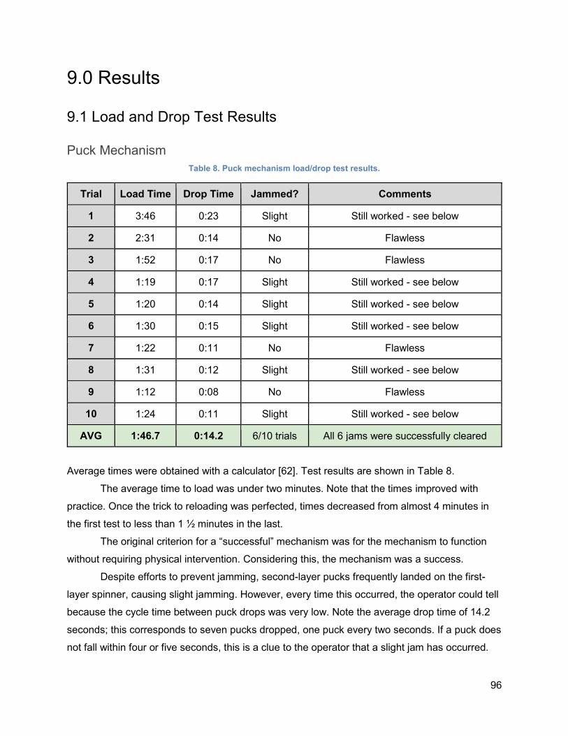
96
9.0 Results
9.1 Load and Drop Test Results
Puck Mechanism
Table 8. Puck mechanism load/drop test results.
Trial Load Time Drop Time Jammed? Comments
1 3:46 0:23 Slight Still worked - see below
2 2:31 0:14 No Flawless
3 1:52 0:17 No Flawless
4 1:19 0:17 Slight Still worked - see below
5 1:20 0:14 Slight Still worked - see below
6 1:30 0:15 Slight Still worked - see below
7 1:22 0:11 No Flawless
8 1:31 0:12 Slight Still worked - see below
9 1:12 0:08 No Flawless
10 1:24 0:11 Slight Still worked - see below
AVG 1:46.7 0:14.2 6/10 trials All 6 jams were successfully cleared
Average times were obtained with a calculator [62]. Test results are shown in Table 8.
The average time to load was under two minutes. Note that the times improved with
practice. Once the trick to reloading was perfected, times decreased from almost 4 minutes in
the first test to less than 1 ½ minutes in the last.
The original criterion for a “successful” mechanism was for the mechanism to function
without requiring physical intervention. Considering this, the mechanism was a success.
Despite efforts to prevent jamming, second-layer pucks frequently landed on the first-
layer spinner, causing slight jamming. However, every time this occurred, the operator could tell
because the cycle time between puck drops was very low. Note the average drop time of 14.2
seconds; this corresponds to seven pucks dropped, one puck every two seconds. If a puck does
not fall within four or five seconds, this is a clue to the operator that a slight jam has occurred.
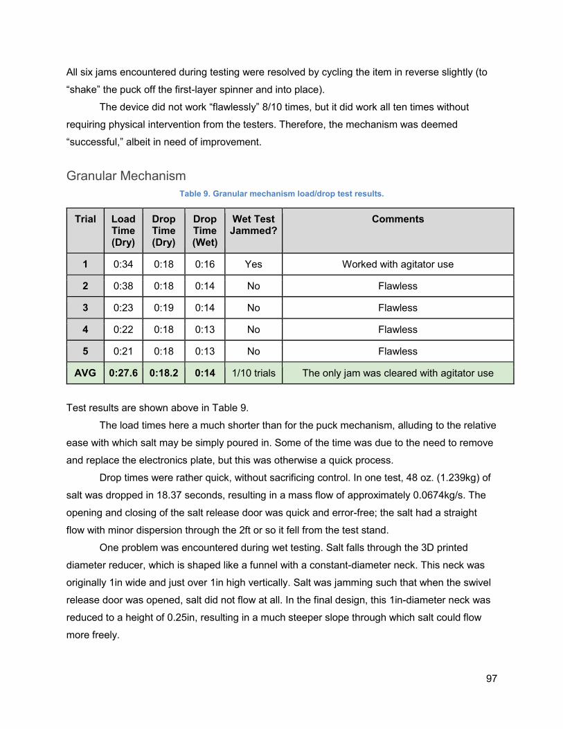
97
All six jams encountered during testing were resolved by cycling the item in reverse slightly (to
“shake” the puck off the first-layer spinner and into place).
The device did not work “flawlessly” 8/10 times, but it did work all ten times without
requiring physical intervention from the testers. Therefore, the mechanism was deemed
“successful,” albeit in need of improvement.
Granular Mechanism
Table 9. Granular mechanism load/drop test results.
Trial Load Time (Dry)
Drop Time (Dry)
Drop Time (Wet)
Wet Test Jammed?
Comments
1 0:34 0:18 0:16 Yes Worked with agitator use
2 0:38 0:18 0:14 No Flawless
3 0:23 0:19 0:14 No Flawless
4 0:22 0:18 0:13 No Flawless
5 0:21 0:18 0:13 No Flawless
AVG 0:27.6 0:18.2 0:14 1/10 trials The only jam was cleared with agitator use
Test results are shown above in Table 9.
The load times here a much shorter than for the puck mechanism, alluding to the relative
ease with which salt may be simply poured in. Some of the time was due to the need to remove
and replace the electronics plate, but this was otherwise a quick process.
Drop times were rather quick, without sacrificing control. In one test, 48 oz. (1.239kg) of
salt was dropped in 18.37 seconds, resulting in a mass flow of approximately 0.0674kg/s. The
opening and closing of the salt release door was quick and error-free; the salt had a straight
flow with minor dispersion through the 2ft or so it fell from the test stand.
One problem was encountered during wet testing. Salt falls through the 3D printed
diameter reducer, which is shaped like a funnel with a constant-diameter neck. This neck was
originally 1in wide and just over 1in high vertically. Salt was jamming such that when the swivel
release door was opened, salt did not flow at all. In the final design, this 1in-diameter neck was
reduced to a height of 0.25in, resulting in a much steeper slope through which salt could flow
more freely.
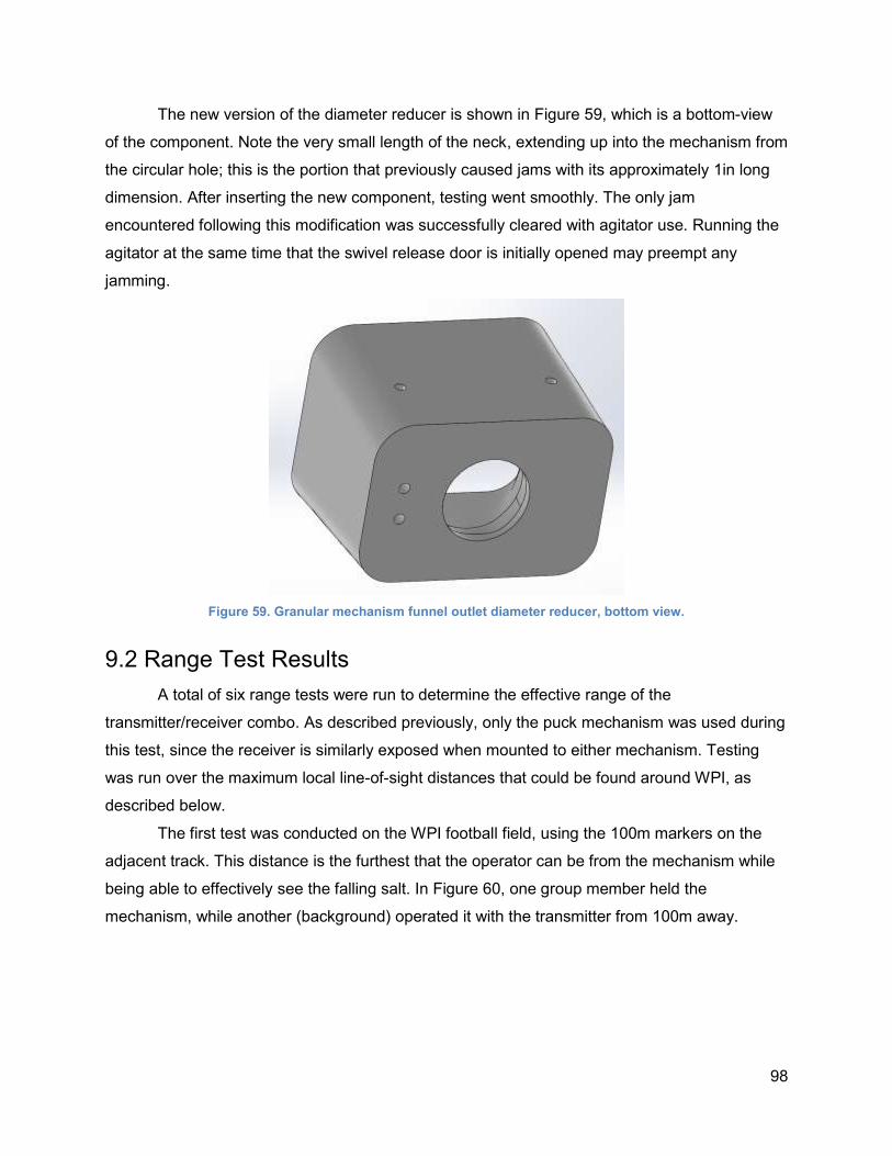
98
The new version of the diameter reducer is shown in Figure 59, which is a bottom-view
of the component. Note the very small length of the neck, extending up into the mechanism from
the circular hole; this is the portion that previously caused jams with its approximately 1in long
dimension. After inserting the new component, testing went smoothly. The only jam
encountered following this modification was successfully cleared with agitator use. Running the
agitator at the same time that the swivel release door is initially opened may preempt any
jamming.
Figure 59. Granular mechanism funnel outlet diameter reducer, bottom view.
9.2 Range Test Results
A total of six range tests were run to determine the effective range of the
transmitter/receiver combo. As described previously, only the puck mechanism was used during
this test, since the receiver is similarly exposed when mounted to either mechanism. Testing
was run over the maximum local line-of-sight distances that could be found around WPI, as
described below.
The first test was conducted on the WPI football field, using the 100m markers on the
adjacent track. This distance is the furthest that the operator can be from the mechanism while
being able to effectively see the falling salt. In Figure 60, one group member held the
mechanism, while another (background) operated it with the transmitter from 100m away.
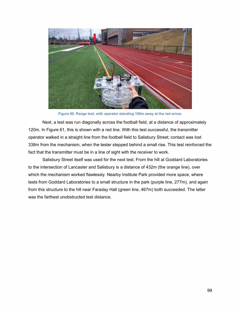
99
Figure 60. Range test, with operator standing 100m away at the red arrow.
Next, a test was run diagonally across the football field, at a distance of approximately
120m. In Figure 61, this is shown with a red line. With this test successful, the transmitter
operator walked in a straight line from the football field to Salisbury Street; contact was lost
338m from the mechanism, when the tester stepped behind a small rise. This test reinforced the
fact that the transmitter must be in a line of sight with the receiver to work.
Salisbury Street itself was used for the next test. From the hill at Goddard Laboratories
to the intersection of Lancaster and Salisbury is a distance of 432m (the orange line), over
which the mechanism worked flawlessly. Nearby Institute Park provided more space, where
tests from Goddard Laboratories to a small structure in the park (purple line, 277m), and again
from this structure to the hill near Faraday Hall (green line, 467m) both succeeded. The latter
was the farthest unobstructed test distance.
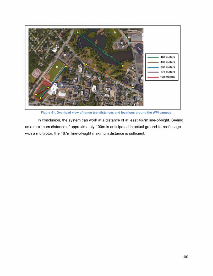
100
Figure 61. Overhead view of range test distances and locations around the WPI campus.
In conclusion, the system can work at a distance of at least 467m line-of-sight. Seeing
as a maximum distance of approximately 100m is anticipated in actual ground-to-roof usage
with a multirotor, the 467m line-of-sight maximum distance is sufficient.
101
10.0 Conclusions
Noticing the lack of affordable and reliable ice dam mitigation technologies, emerging
UAS technology was used to help solve the problem of precision ice-melt deployment. As the
popularity of enthusiast drones like the DJI Phantom and concepts such as Amazon Prime Air
shows, this technology may have a myriad of unexplored applications, such as the one first
explored here. The emphasis on use of a commercially-available drone is perhaps indicative of
the potential this industry has yet to explore.
Focus was placed on the development of a standard mounting and payload system for
at least one multirotor model, in order to drop salt pucks and granular ice melting salt onto
winter roofs. A number of existing solutions (ranging from the inexpensive to the inadvisable)
were explored, and cost-efficient mitigation of pre-existing ice dams was an area found to be
lacking. Improvement of the process of throwing salt onto roofs (which is imprecise or
damaging) was of greatest concern.
A number of multirotor payload designs were conceptualized to solve this problem. Two
separate designs were iterated upon to drop the two different physical formats of salt. In an
application prone to occasional crashes or collisions, the use of rapid prototyping technologies
was emphasized in order to quickly manufacture or repair the mechanisms.
The result was two lightweight mechanisms capable of being transported by the DJI
S900 or S1000+ multirotor models. The puck deployment mechanism carries seven pucks
(0.7kg) of Roofmelt ice pucks, while the granular deployment mechanism carries 1.239kg of pet-
safe ice melt, both of which are available at area hardware stores.
Each mechanism implements a common mounting situation and power/control system
independent of the multirotor flight systems. They rely upon manual line-of-sight operation for
the time being, due to the lack of access that this project had to a multirotor. Regardless, the
first generation prototype of each mechanism functioned sufficiently without requiring physical
intervention. All jams were clearable remotely. Short payload deployment times and relative
ease of reloading for both mechanisms make the entire operation process efficient for skilled
operators. Several improvements must be made to enhance functionality and operation of the
mechanisms.
102
10.1 Recommendations
The granular mechanism was the more reliable of the two mechanisms, owing to its
relative simplicity. Operation could be streamlined by incorporating a “ball valve” release within
the bottom of the funnel, as opposed to a swiveling door. This would eliminate bending
moments inherent to the current design due to the weight of granular salt that is in contact with
the door. Alternatively, a guide at the point farthest from the door’s axle could be implemented
to ease these moments by prohibiting the door from bending.
The agitator of this mechanism could also be converted to a vertical arrangement, such
that the end of the agitator would rest directly above or within the outlet of the diameter reducer.
This could be achieved by carefully modifying the electronics and mounting locations, and would
allow granular salt to be more effectively stirred and made to flow out of the funnel in the event
of a jam. Additionally, the agitator could be composed of a corkscrew or auger-shaped
component instead of a flat, rectangular panel, in order to better-promote flow and reduce strain
on the agitator motor.
Initial ideation for the puck deployment mechanism led to a number of ideas using
vertical puck tubes, for ease of loading and small form factor. It is anticipated that a vertical tube
arrangement would be much simpler and more compact than the current arrangement, in both
operation and during the action of reloading. Manufacturability concerns led to these ideas not
being prototyped, but future projects may find success in this area. The single largest drawback
of the current puck mechanism is the practice required to quickly and properly reload the
mechanism.
It may be possible to implement some degree of automation in the puck dropping action,
or to drop a certain pre-prescribed mass of granular salt. A microcontroller such as an Arduino,
interfacing between the motors and the receiver, may remove the need to manually drop pucks
or granular salt. It is recommended that this option be explored by future projects, seeing as it
would allow operation of the mechanisms to be much less dependent on imprecise operator
input.
Lastly, to ease the reloading processes for both mechanisms, small stands
(permanently-affixed, lightweight “landing legs”) could be implemented onto the body of each
mechanism. This would allow the mechanisms to stand upright without needing to be placed in
the mounting stand. Finally, a more extensive standard mechanism mounting plate with
integrated driving electronics could be designed, as the mechanisms currently rely upon a
removable electronics plate that must be interchanged between mechanisms.
103
10.2 Business Plan
The initial project goal was to provide very low-cost ice dam control and removal
services to area households using the prototyped mechanisms. This would have granted the
opportunities for the two prototypes and overall system to be tested on ice-dam-affected homes,
while using revenue to recoup some of the costs of the components used. Such a business plan
calls into question a number of liability and legality concerns, especially with respect to the
commercial operation of a UAS, as discussed in Section 3.3.6. For this reason, this plan was
determined to be infeasible for this project. Even if the legal concerns had been addressed and
worked with, the 2015-2016 winter season did not provide sufficient snowfall for the formation of
significant ice dams, and therefore, it is unlikely that this plan could have been carried out.
104
11.0 Works Cited
[1] "UAV or UAS?" Unmanned Aerial Vehicle Systems Association. 2016. Web. 02 Mar. 2016.
<https://www.uavs.org/index.php?page=what_is>.
[2] "The UAV - The Future Of The Sky." TheUAV.com. Web. 02 Mar. 2016.
<http://www.theuav.com/>.
[3] "Definition of Propeller in English." Oxford Dictionaries. Web. 02 Mar. 2016.
<http://www.oxforddictionaries.com/us/definition/american_english/propeller>.
[4] "2014-2015 Snow Totals." Golden Snow Globe National Snow Contest Snowiest US City
Pop 100000+. Web. 02 Mar. 2016. <http://goldensnowglobe.com/all-past-snow-seasons-
winners/2014-2015-snow-totals/>.
[5] Larson, Timothy, Lewis Hendricks, and Patrick Huelman. "Ice Dams." Moisture Management
: Housing and Technology : Environment : University of Minnesota Extension. Ed.
Richard Stone. University of Minnesota. Web. 02 Mar. 2016.
<http://www.extension.umn.edu/environment/housing-technology/moisture-
management/ice-dams/>.
[6] Fisette, Paul. "Preventing Ice Dams." Building and Construction Technology: University of
Massachusetts, Amherst. UMass Amherst, 27 Dec. 2015. Web. 2 Mar. 2016.
<https://bct.eco.umass.edu/publications/by-title/preventing-ice-dams/>.
[7] "Ice Dam Prevention." The Ice Dam Company. Web. 02 Mar. 2016.
<http://www.icedamcompany.com/about-ice-dams/ice-dam-prevention/>.
[8] "The Importance of Proper Attic Ventilation to the Roofing System." Asphalt Roofing
Manufacturers Association (ARMA). Web. 02 Mar. 2016.
<http://www.asphaltroofing.org/press-room/press-releases/importance-proper-attic-
ventilation-roofing-system>.
[9] "Easy Heat ADKS-600 120-Foot Roof Snow De-Icing Kit." Amazon.com : : Roof Cables :
Patio, Lawn & Garden. Amazon. Web. 02 Mar. 2016. <http://www.amazon.com/Easy-
Heat-ADKS-600-120-Foot--Icing/dp/B0000DGAKO/ref=sr_1_1?s=lawn-
garden&ie=UTF8&qid=1455481116&sr=1-1&keywords=roof%2Bheat%2Bcable>.
[10] "Avalanche - Original Roof Snow Removal System AVA500 with 17-Inch Wide Cutting
Head and 16-Foot Quick Connect Handle." Amazon : : Patio, Lawn & Garden. Amazon.
Web. 02 Mar. 2016.
<http://www.amazon.com/gp/product/B002TLSTH4/ref=s9_top_hd_bw_bClkZ_g86_i4?pf
_rd_m=ATVPDKIKX0DER&pf_rd_s=merchandised-search-
105
2&pf_rd_r=1F5FCB9RE52MFQQNJ186&pf_rd_t=101&pf_rd_p=2405862282&pf_rd_i=3
043491>.
[11] "Roofmelt Ice Melt-RM-65 - The Home Depot." The Home Depot. Web. 02 Mar. 2016.
<http://www.homedepot.com/p/Roofmelt-Ice-Melt-RM-65/202536089>.
[12] "Welcome to Roofmelt." Roofmelt. Kassouni Mfg, 2012. Web. 02 Mar. 2016.
<http://roofmelt.dnnstaging.com/>.
[13] Saltzman, Reuben. "How To Remove Ice Dams." Structure Tech Home Inspections. 12
Feb. 2013. Web. 02 Mar. 2016. <http://structuretech1.com/2013/02/how-to-remove-ice-
dams/>.
[14] "Ice Dams – Several Quick Fixes but Only One Cure." Home Partners. Web. 02 Mar. 2016.
<http://home-partners.com/articles/ice-dams-quick-fixes-cure>.
[15] Perry, Leonard. "SALT DAMAGE TO PLANTS." The Green Mountain Gardener. University
of Vermont Extension: Department of Plant and Soil Science. Web. 02 Mar. 2016.
<http://www.uvm.edu/pss/ppp/articles/salt1.htm>.
[16] Chambers, Caley. "Is There Really a ‘safe’ ice melt?" Pet Poison Helpline. 26 Nov. 2013.
Web. 02 Mar. 2016. <http://www.petpoisonhelpline.com/uncategorized/really-safe-ice-
melt/>.
[17] "Steam Ice Dam Removal." Platinum Ice Dam Removal. Web. 02 Mar. 2016.
<http://www.pticedamremoval.com/steam-ice-dam-removal/>.
[18] "Ice Dam Removal Cost: Our 2016 Rates." The Ice Dam Company. Web. 02 Mar. 2016.
<http://www.icedamcompany.com/ice-dam-removal/ice-dam-removal/rates/>.
[19] "How Removing Ice Dams Can Keep You Out of Trouble." DKI. Web. 02 Mar. 2016.
<http://www.waterdamage101.com/how-removing-ice-dams-can-keep-you-out-of-
trouble/>.
[20] "Frequently Asked Questions." The Ice Dam Company. Web. 20 Mar. 2016.
<http://www.icedamcompany.com/about-ice-dams/ice-dam-faq/>.
[21] "Massachusetts Ice Dam Removal." Ice Dam Removal Guys. Web. 20 Mar. 2016.
<http://www.icedamremovalguys.com/ma/>.
[22] "Ice Dam Removal." Lavallee Home & Property Services. Web. 02 Mar. 2016.
<http://www.lavalleehps.com/IceDamRemoval.html>.
106
[23] "Massachusetts - Ice Dam Removal." Perfect Power Wash. Web. 02 Mar. 2016.
<http://www.perfectpowerwash.net/Ice-Dam-Removal-Massachusetts.html>.
[24] "Ice Dam Removal Service." Quality Cleaning & Restoration. Web. 02 Mar. 2016.
<http://www.qualitywaterdamage.com/ice-dam-removal-worcester-ma.html>.
[25] "What Are Ice Dams?" Noreaster Roofing Inc. Web. 02 Mar. 2016.
<http://www.noreasterroofing.com/roofing-contractor-ma/ice-dam-removal-ma/>.
[26] "What’s in a Pet Friendly Ice Melter?" Ossian Inc. Web. 02 Mar. 2016.
<http://www.ossian.com/petsafe_doc.htm>.
[27] "Multirotor Beerlift 2015." HobbyKing. Web. 02 Mar. 2016.
<http://www.hobbyking.com/hobbyking/store/beerlift.asp>.
[28] "Buy Phantom 3 Standard." DJI Store. DJI. Web. 02 Mar. 2016.
<http://store.dji.com/product/phantom-3-standard>.
[29] "Buy Phantom 2." DJI Store. DJI. Web. 02 Mar. 2016.
<http://store.dji.com/product/phantom-2?from=buy_now>.
[30] Mills, Toby. "3DR X8 RTF Unboxing / Test." DIY Drones. 25 Apr. 2014. Web. 02 Mar. 2016.
<http://diydrones.com/profiles/blogs/3dr-x8-2014-rtf-unboxing>.
[31] "3DR X8+ Octocopter (RTF, 915 MHz)." B&H. B&H Foto & Electronics Corp. Web. 02 Mar.
2016. <http://www.bhphotovideo.com/c/product/1098148-
REG/3d_robotics_3dr0252_x8_octocopter_rtf_915.html>.
[32] Cox, Spencer. "3D Robotics X8+ Drone Review." Photography Life. 11 July 2015. Web. 02
Mar. 2016. <https://photographylife.com/reviews/3d-robotics-x8-drone>.
[33] Anderson, Chris. "3DR's Evolution from Micro to Mass." DIY Drones. 2 Nov. 2015. Web. 02
Mar. 2016. <http://diydrones.com/profiles/blogs/3dr-s-evolution-from-micro-to-mass>.
[34] "Spreading Wings S900 Specs." DJI. Web. 02 Mar. 2016.
<http://www.dji.com/product/spreading-wings-s900/info#specs>.
[35] "Buy Spreading Wings S900." DJI Store. DJI. Web. 02 Mar. 2016.
<http://store.dji.com/spreading-wings/s900?site=brandsite&from=buy_now_bar>.
[36] "Buy Spreading Wings S1000+." DJI Store. DJI. Web. 02 Mar. 2016.
<http://store.dji.com/product/spreading-wings-s1000-plus>.

107
[37] "Buy Spreading Wings S1000+." DJI Store. DJI. Web. 02 Mar. 2016.
<http://store.dji.com/spreading-wings/s1000-plus>.
[38] "Spreading Wings S1000+ Specs." DJI. Web. 02 Mar. 2016.
<http://www.dji.com/product/spreading-wings-s1000-plus/info#specs>.
[39] "Wire Gauges - Current Ratings." The Engineering ToolBox. Web. 02 Mar. 2016.
<http://www.engineeringtoolbox.com/wire-gauges-d_419.html>.
[40] "PUBLIC ENTITIES." Know Before You Fly. Federal Aviation Administration. Web. 02 Mar.
2016. <http://knowbeforeyoufly.org/for-public-entities/>.
[41] "RECREATIONAL USERS." Know Before You Fly. Federal Aviation Administration. Web.
02 Mar. 2016. <http://knowbeforeyoufly.org/for-recreational-users/>.
[42] "DRONE REGISTRATION." Know Before You Fly. Federal Aviation Administration. Web.
02 Mar. 2016. <http://knowbeforeyoufly.org/register-your-drone/>.
[43] "What Can I Do With My Small Unmanned Aircraft?" Federal Aviation Administration. Web.
02 Mar. 2016. <http://www.faa.gov/uas/publications/model_aircraft_operators/>.
[44] "BUSINESS USERS." Know Before You Fly. Federal Aviation Administration. Web. 02 Mar.
2016. <http://knowbeforeyoufly.org/for-business-users/>.
[45] "Section 333." Federal Aviation Administration. Web. 02 Mar. 2016.
<https://www.faa.gov/uas/legislative_programs/section_333/>.
[46] Bresien, Tim. "Innovation Takes Flight: Commercial use in the U.S. and around the world."
Rotor Drone Magazine Jan.-Feb. 2015: 44-49. Print.
[47] "Scotwood 9. 5J-RR-MAG 9. 5 Lbs. Pet Friendly Ice Melt." Walmart.com. Walmart. Web. 02
Mar. 2016. <http://www.walmart.com/ip/Scotwood-9.-5J-RR-MAG-9.-5-lbs.-Pet-Friendly-
Ice-Melt/47641753>.
[48] "BLIMP IT - Solution Aérienne Broadcast." BLIMP IT - Solution Aérienne Broadcast. Web.
02 Mar. 2016. <http://blimp-it.fr/S900.html>.
[49] "A Few Flight Related Terms." NoRunway.com. 28 June 2014. Web. 02 Mar. 2016.
<http://norunway.com/wp/flight-related-terms/>.
[50] "Spreading Wings S1000 User Manual V 1.10." DJI. Web. 2 Mar. 2016.
<http://dl.djicdn.com/downloads/s1000/en/S1000_User_Manual_v1.10_en.pdf>.
[51] "Density of Materials." Psyclops.com. Web. 2 Mar. 2016.
<http://www.psyclops.com/tools/technotes/materials/density.html>.
108
[52] "Polylactic Acid (PLA, Polylactide)." MakeItFrom.com. Web. 02 Mar. 2016.
<http://www.makeitfrom.com/material-properties/Polylactic-Acid-PLA-Polylactide/>.
[53] "Acrylic vs. Polycarbonate: A Quantitative and Qualitative Comparison." Hydrosight. Web.
02 Mar. 2016. <http://www.hydrosight.com/acrylic-vs-polycarbonate-a-quantitative-and-
qualitative-comparison/>.
[54] "MakerBot Replicator 2 Desktop 3D Printer." MakerBot Store. MakerBot Industries, LLC.
Web. 02 Mar. 2016. <https://store.makerbot.com/replicator2.html>.
[55] "All About Stainless Steel." Berkeley Point. Web. 02 Mar. 2016.
<http://www.berkeleypoint.com/learning/stainless.html>.
[56] "ANSI External Screw Threads Size Tolerances Chart." Engineers Edge. Web. 02 Mar.
2016. <http://www.engineersedge.com/screw_threads_chart.htm>.
[57] "Stainless Steel Fasteners." Designer Handbook. Ssina.com. Web. 2 Mar. 2016.
<http://www.ssina.com/download_a_file/fasteners.pdf>.
[58] "Motors." VEX Robotics. Web. 02 Mar. 2016. <http://www.vexrobotics.com/motors.html>.
[59] VEX Inventor's Guide - 2-Wire Motor 269. VEX Robotics. Web. 2 Mar. 2016.
<http://content.vexrobotics.com/docs/inventors-guide/2-wire-269-inst.pdf>.
[60] "GoolRC Flysky FS-i6 AFHDS 2A 2.4GHz 6CH Radio System Transmitter for RC
Helicopter Glider with FS-iA6 Receiver." Amazon : : Toys & Games. Amazon. Web. 02
Mar. 2016. <http://www.amazon.com/Flysky-2-4GHz-Transmitter-Helicopter-
Receiver/dp/B00VE3PZ3Y>.
[61]: "Definition of Rotor in English." Oxford Dictionaries. Web. 02 Mar. 2016.
<http://www.oxforddictionaries.com/us/definition/american_english/rotor>.
[62] "Time Calculator." Grun1.com. Web. 02 Mar. 2016.
<http://www.grun1.com/utils/timeCalc.html>.
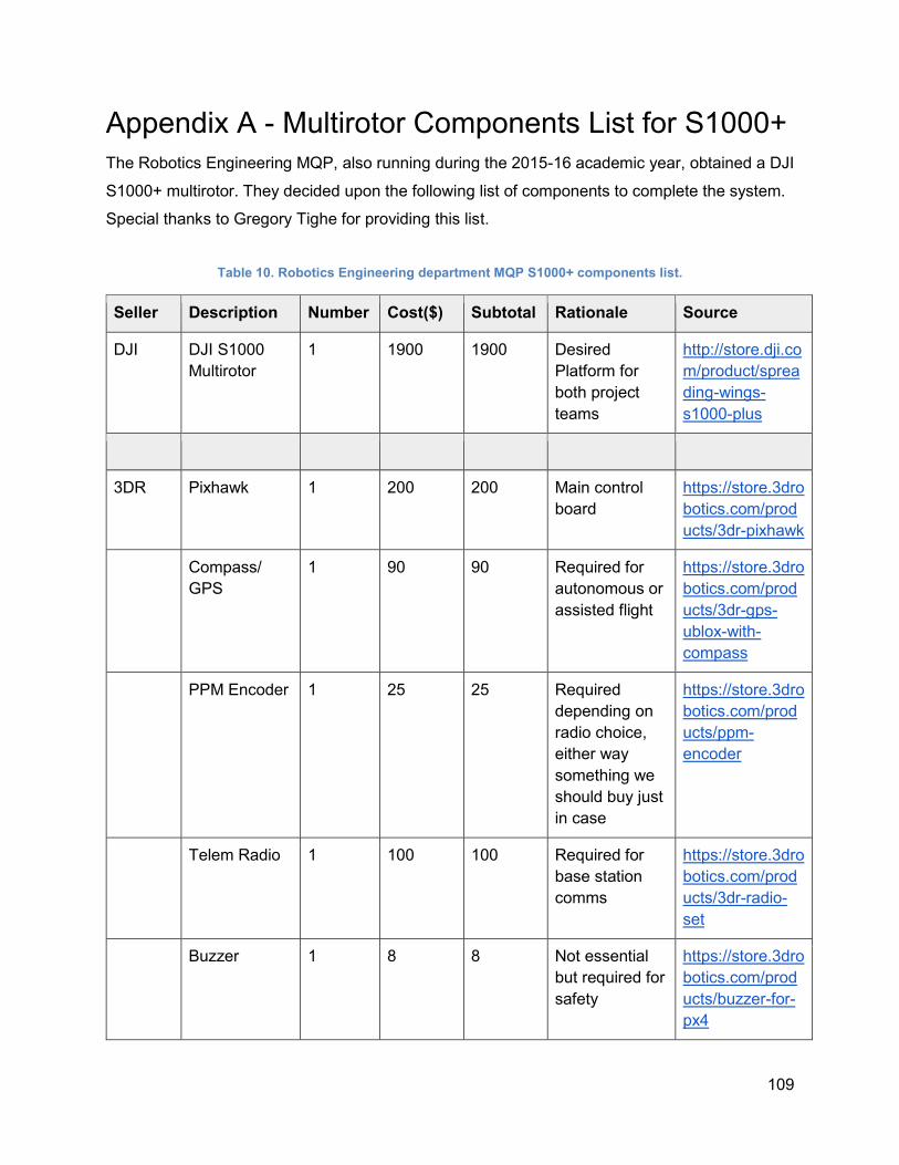
109
Appendix A - Multirotor Components List for S1000+
The Robotics Engineering MQP, also running during the 2015-16 academic year, obtained a DJI
S1000+ multirotor. They decided upon the following list of components to complete the system.
Special thanks to Gregory Tighe for providing this list.
Table 10. Robotics Engineering department MQP S1000+ components list.
Seller Description Number Cost($) Subtotal Rationale Source
DJI DJI S1000
Multirotor
1 1900 1900 Desired
Platform for
both project
teams
http://store.dji.co
m/product/sprea
ding-wings-
s1000-plus
3DR Pixhawk 1 200 200 Main control
board
https://store.3dro
botics.com/prod
ucts/3dr-pixhawk
Compass/
GPS
1 90 90 Required for
autonomous or
assisted flight
https://store.3dro
botics.com/prod
ucts/3dr-gps-
ublox-with-
compass
PPM Encoder 1 25 25 Required
depending on
radio choice,
either way
something we
should buy just
in case
https://store.3dro
botics.com/prod
ucts/ppm-
encoder
Telem Radio 1 100 100 Required for
base station
comms
https://store.3dro
botics.com/prod
ucts/3dr-radio-
set
Buzzer 1 8 8 Not essential
but required for
safety
https://store.3dro
botics.com/prod
ucts/buzzer-for-
px4
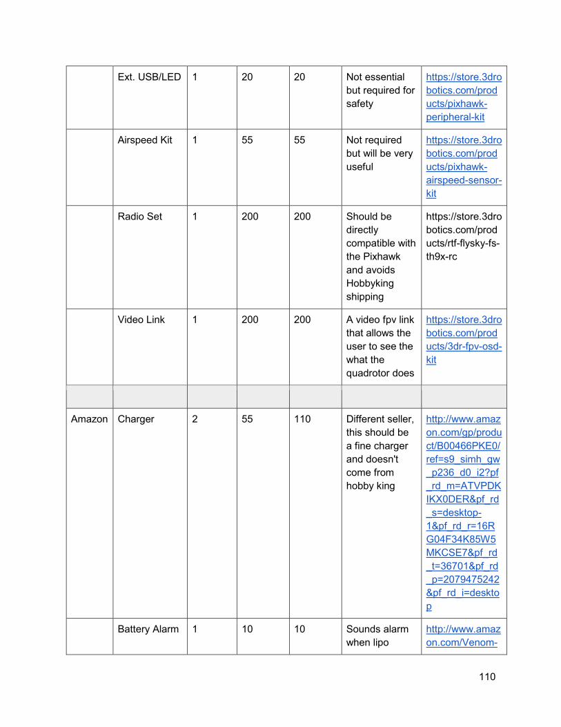
110
Ext. USB/LED 1 20 20 Not essential
but required for
safety
https://store.3dro
botics.com/prod
ucts/pixhawk-
peripheral-kit
Airspeed Kit 1 55 55 Not required
but will be very
useful
https://store.3dro
botics.com/prod
ucts/pixhawk-
airspeed-sensor-
kit
Radio Set 1 200 200 Should be
directly
compatible with
the Pixhawk
and avoids
Hobbyking
shipping
https://store.3dro
botics.com/prod
ucts/rtf-flysky-fs-
th9x-rc
Video Link 1 200 200 A video fpv link
that allows the
user to see the
what the
quadrotor does
https://store.3dro
botics.com/prod
ucts/3dr-fpv-osd-
kit
Amazon Charger 2 55 110 Different seller,
this should be
a fine charger
and doesn't
come from
hobby king
http://www.amaz
on.com/gp/produ
ct/B00466PKE0/
ref=s9_simh_gw
_p236_d0_i2?pf
_rd_m=ATVPDK
IKX0DER&pf_rd
_s=desktop-
1&pf_rd_r=16R
G04F34K85W5
MKCSE7&pf_rd
_t=36701&pf_rd
_p=2079475242
&pf_rd_i=deskto
p
Battery Alarm 1 10 10 Sounds alarm
when lipo
http://www.amaz
on.com/Venom-
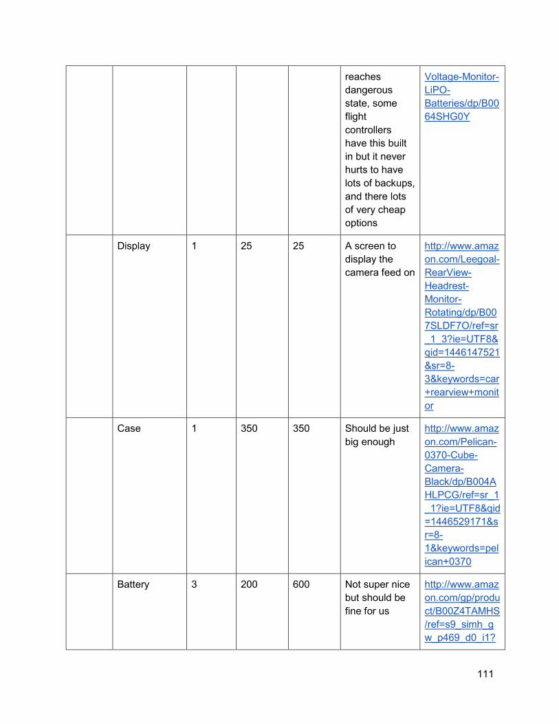
111
reaches
dangerous
state, some
flight
controllers
have this built
in but it never
hurts to have
lots of backups,
and there lots
of very cheap
options
Voltage-Monitor-
LiPO-
Batteries/dp/B00
64SHG0Y
Display 1 25 25 A screen to
display the
camera feed on
http://www.amaz
on.com/Leegoal-
RearView-
Headrest-
Monitor-
Rotating/dp/B00
7SLDF7O/ref=sr
_1_3?ie=UTF8&
qid=1446147521
&sr=8-
3&keywords=car
+rearview+monit
or
Case 1 350 350 Should be just
big enough
http://www.amaz
on.com/Pelican-
0370-Cube-
Camera-
Black/dp/B004A
HLPCG/ref=sr_1
_1?ie=UTF8&qid
=1446529171&s
r=8-
1&keywords=pel
ican+0370
Battery 3 200 600 Not super nice
but should be
fine for us
http://www.amaz
on.com/gp/produ
ct/B00Z4TAMHS
/ref=s9_simh_g
w_p469_d0_i1?
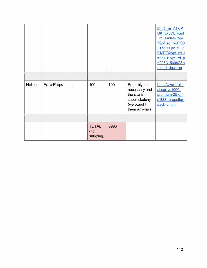
112
pf_rd_m=ATVP
DKIKX0DER&pf
_rd_s=desktop-
7&pf_rd_r=0TS0
3TN2YQA97GV
GMFTQ&pf_rd_t
=36701&pf_rd_p
=2253156982&p
f_rd_i=desktop
Helipal Extra Props 1 100 100 Probably not
necessary and
the site is
super sketchy
(we bought
them anyway)
http://www.helip
al.com/s1000-
premium-25-dji-
s1000-propeller-
pack-8.html
TOTAL
(no
shipping)
3993
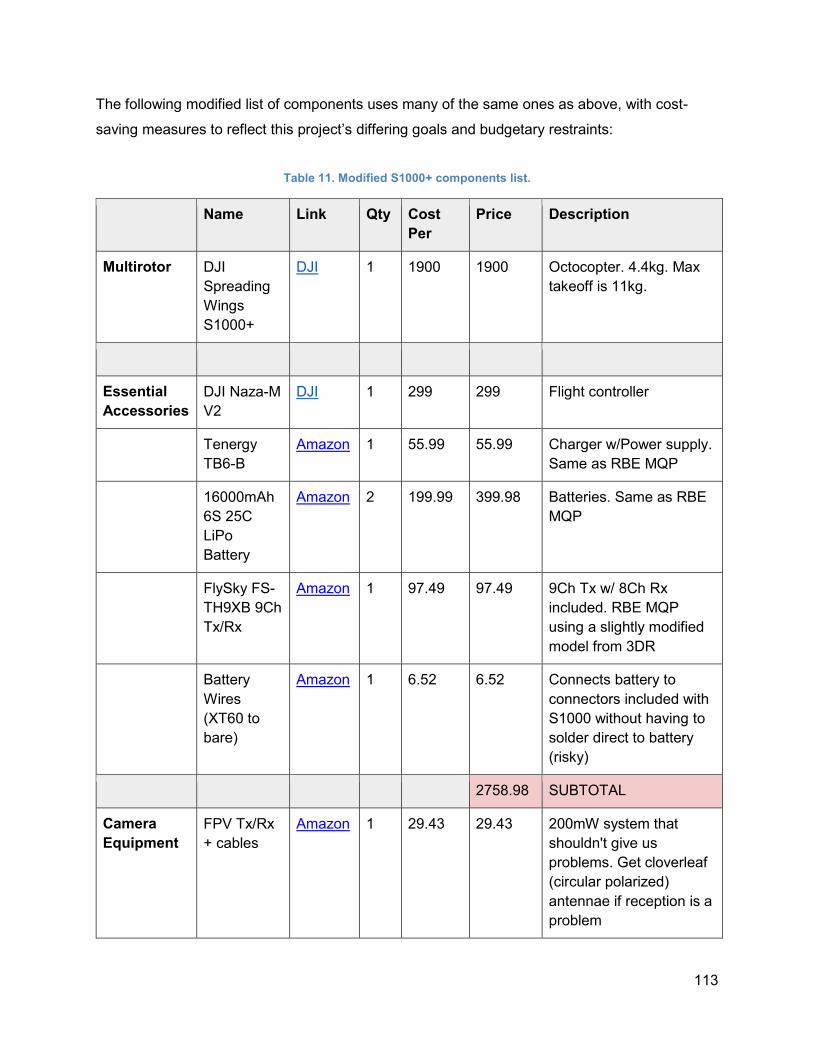
113
The following modified list of components uses many of the same ones as above, with cost-
saving measures to reflect this project’s differing goals and budgetary restraints:
Table 11. Modified S1000+ components list.
Name Link Qty Cost
Per
Price Description
Multirotor DJI
Spreading
Wings
S1000+
DJI 1 1900 1900 Octocopter. 4.4kg. Max
takeoff is 11kg.
Essential
Accessories
DJI Naza-M
V2
DJI 1 299 299 Flight controller
Tenergy
TB6-B
Amazon 1 55.99 55.99 Charger w/Power supply.
Same as RBE MQP
16000mAh
6S 25C
LiPo
Battery
Amazon 2 199.99 399.98 Batteries. Same as RBE
MQP
FlySky FS-
TH9XB 9Ch
Tx/Rx
Amazon 1 97.49 97.49 9Ch Tx w/ 8Ch Rx
included. RBE MQP
using a slightly modified
model from 3DR
Battery
Wires
(XT60 to
bare)
Amazon 1 6.52 6.52 Connects battery to
connectors included with
S1000 without having to
solder direct to battery
(risky)
2758.98 SUBTOTAL
Camera
Equipment
FPV Tx/Rx
+ cables
Amazon 1 29.43 29.43 200mW system that
shouldn't give us
problems. Get cloverleaf
(circular polarized)
antennae if reception is a
problem
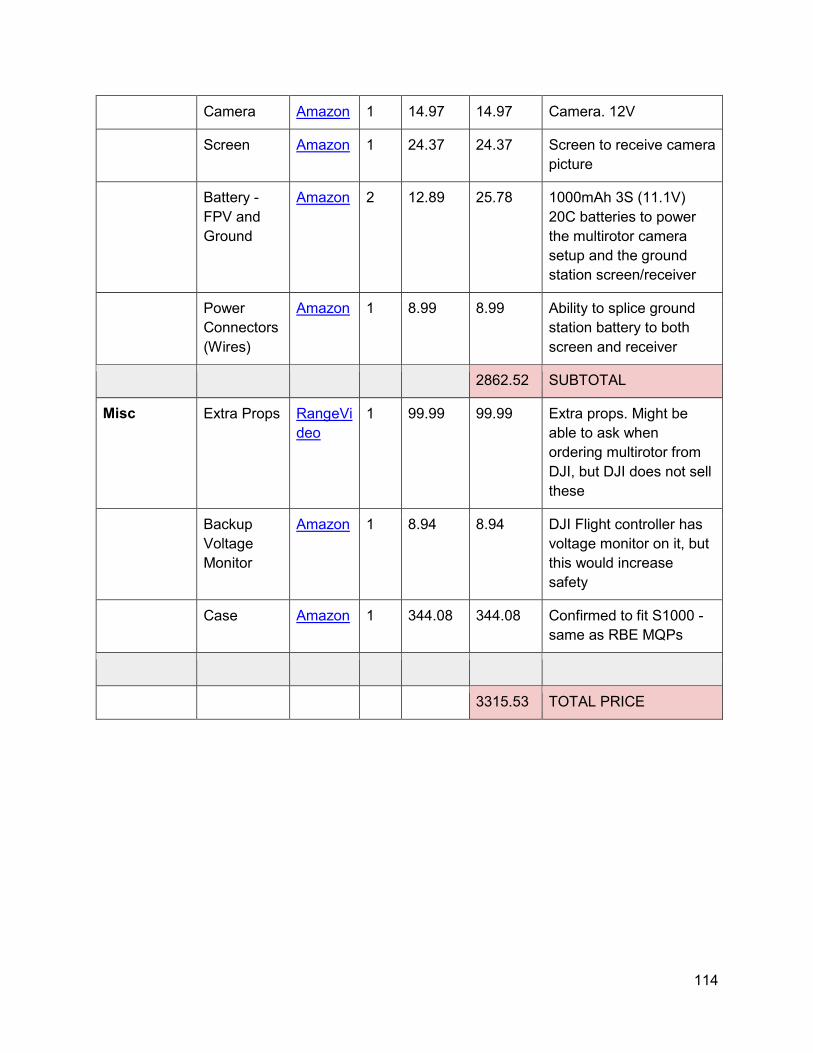
114
Camera Amazon 1 14.97 14.97 Camera. 12V
Screen Amazon 1 24.37 24.37 Screen to receive camera
picture
Battery -
FPV and
Ground
Amazon 2 12.89 25.78 1000mAh 3S (11.1V)
20C batteries to power
the multirotor camera
setup and the ground
station screen/receiver
Power
Connectors
(Wires)
Amazon 1 8.99 8.99 Ability to splice ground
station battery to both
screen and receiver
2862.52 SUBTOTAL
Misc Extra Props RangeVi
deo
1 99.99 99.99 Extra props. Might be
able to ask when
ordering multirotor from
DJI, but DJI does not sell
these
Backup
Voltage
Monitor
Amazon 1 8.94 8.94 DJI Flight controller has
voltage monitor on it, but
this would increase
safety
Case Amazon 1 344.08 344.08 Confirmed to fit S1000 -
same as RBE MQPs
3315.53 TOTAL PRICE
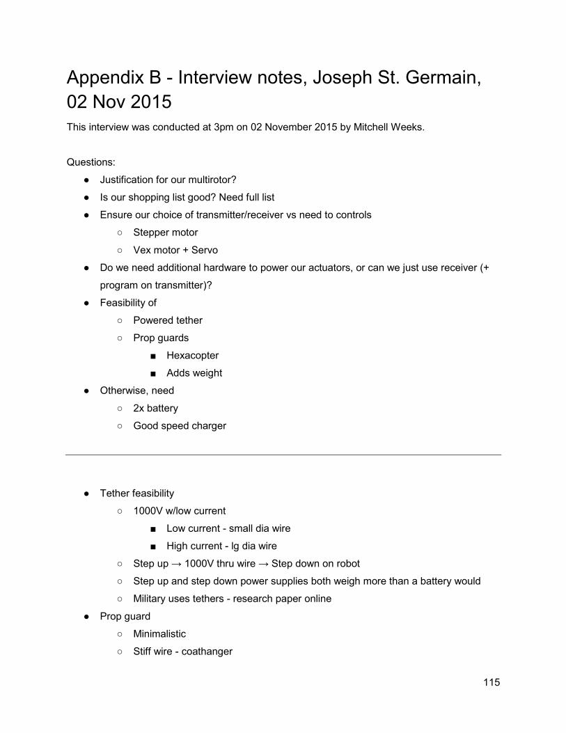
115
Appendix B - Interview notes, Joseph St. Germain,
02 Nov 2015
This interview was conducted at 3pm on 02 November 2015 by Mitchell Weeks.
Questions:
● Justification for our multirotor?
● Is our shopping list good? Need full list
● Ensure our choice of transmitter/receiver vs need to controls
○ Stepper motor
○ Vex motor + Servo
● Do we need additional hardware to power our actuators, or can we just use receiver (+
program on transmitter)?
● Feasibility of
○ Powered tether
○ Prop guards
■ Hexacopter
■ Adds weight
● Otherwise, need
○ 2x battery
○ Good speed charger
● Tether feasibility
○ 1000V w/low current
■ Low current - small dia wire
■ High current - lg dia wire
○ Step up → 1000V thru wire → Step down on robot
○ Step up and step down power supplies both weigh more than a battery would
○ Military uses tethers - research paper online
● Prop guard
○ Minimalistic
○ Stiff wire - coathanger
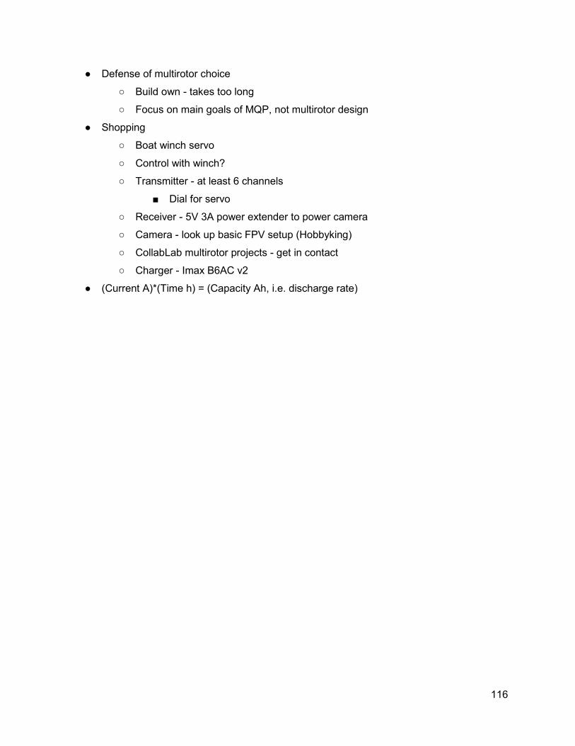
116
● Defense of multirotor choice
○ Build own - takes too long
○ Focus on main goals of MQP, not multirotor design
● Shopping
○ Boat winch servo
○ Control with winch?
○ Transmitter - at least 6 channels
■ Dial for servo
○ Receiver - 5V 3A power extender to power camera
○ Camera - look up basic FPV setup (Hobbyking)
○ CollabLab multirotor projects - get in contact
○ Charger - Imax B6AC v2
● (Current A)*(Time h) = (Capacity Ah, i.e. discharge rate)
117
Appendix C - Roofmelt Ice Puck Friction
Calculations
The puck-form-factor ice melt is standard Roofmelt Ice Melt, available in New England at
Home Depot (http://www.homedepot.com/p/Roofmelt-Ice-Melt-RM-65/202536089) or Lowe’s
(http://www.lowes.com/pd_363600-13902-12190065_0__?productId=3824269). This is a
Calcium Chloride (CaCl2) composition in the form of irregular 2.25in diamater, 1in height discs.
An experiment was devised to find the friction between these pucks and a flat cast-acrylic sheet,
across which they would slide in the final puck mechanism.
Materials:
● 2N Force Gauge
● Scale
● String
● Salt Pucks (CaCl2, obtained at Lowe’s in a 14lb bucket)
● Cast Acrylic Sheet
● Paper Towels
● Water
Procedure:
Dry Salt Pucks
1. Place paper towel on scale and zero it.
2. Place salt puck on scale and record mass.
3. Place salt puck flat-face-down on acrylic sheet.
4. Using force gauge, pull on salt puck and record the force reading just before salt puck
begins to move (static force). Be careful not to let force gauge rest on the salt puck;
rather, only the hook at the end should make contact.
5. Using force gauge, pull on salt puck and record the force reading as it moves at a
constant velocity (kinetic force).
6. Wipe CaCl2 dust off acrylic sheet.
7. Repeat steps 1-6 four more times.
8. Repeat steps 1-6 five times, but now use a string wrapped around the salt puck to
interface with the force gauge.
Wet Salt Pucks
9. Repeat steps 1-8 ten times, but with the following changes:
a. In step 2, lightly moisten one face of salt puck before finding mass.
b. In step 3, place the salt puck moist-face-down on the acrylic sheet.
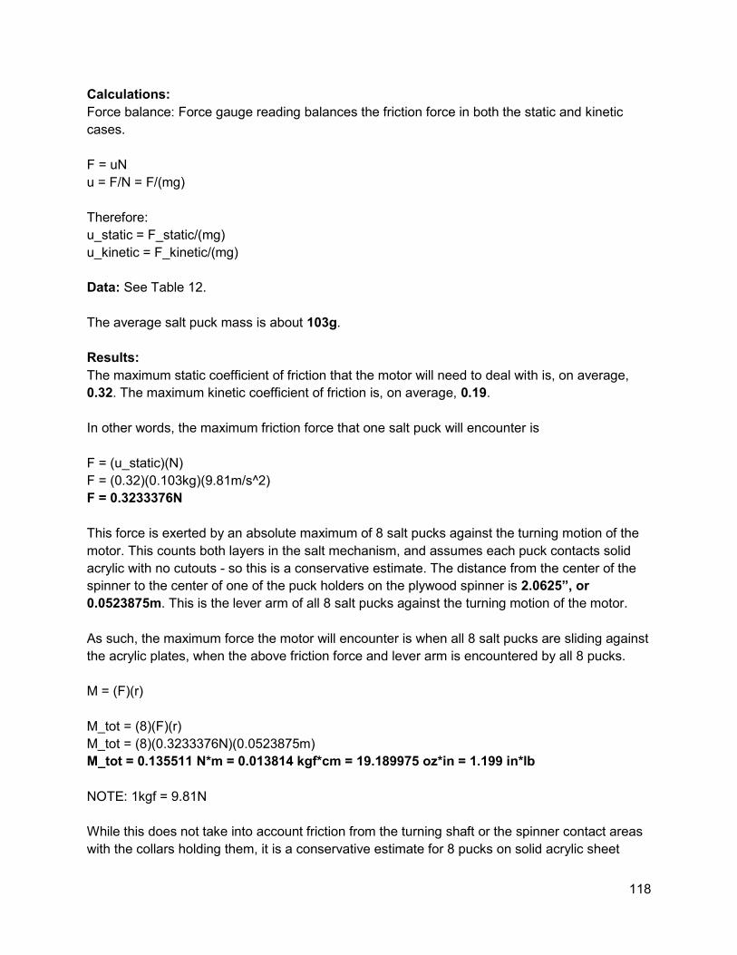
118
Calculations:
Force balance: Force gauge reading balances the friction force in both the static and kinetic
cases.
F = uN
u = F/N = F/(mg)
Therefore:
u_static = F_static/(mg)
u_kinetic = F_kinetic/(mg)
Data: See Table 12.
The average salt puck mass is about 103g.
Results:
The maximum static coefficient of friction that the motor will need to deal with is, on average,
0.32. The maximum kinetic coefficient of friction is, on average, 0.19.
In other words, the maximum friction force that one salt puck will encounter is
F = (u_static)(N)
F = (0.32)(0.103kg)(9.81m/s^2)
F = 0.3233376N
This force is exerted by an absolute maximum of 8 salt pucks against the turning motion of the
motor. This counts both layers in the salt mechanism, and assumes each puck contacts solid
acrylic with no cutouts - so this is a conservative estimate. The distance from the center of the
spinner to the center of one of the puck holders on the plywood spinner is 2.0625”, or
0.0523875m. This is the lever arm of all 8 salt pucks against the turning motion of the motor.
As such, the maximum force the motor will encounter is when all 8 salt pucks are sliding against
the acrylic plates, when the above friction force and lever arm is encountered by all 8 pucks.
M = (F)(r)
M_tot = (8)(F)(r)
M_tot = (8)(0.3233376N)(0.0523875m)
M_tot = 0.135511 N*m = 0.013814 kgf*cm = 19.189975 oz*in = 1.199 in*lb
NOTE: 1kgf = 9.81N
While this does not take into account friction from the turning shaft or the spinner contact areas
with the collars holding them, it is a conservative estimate for 8 pucks on solid acrylic sheet
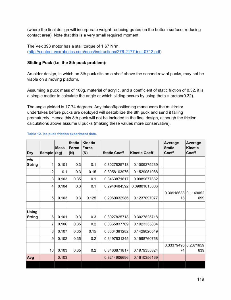
119
(where the final design will incorporate weight-reducing grates on the bottom surface, reducing
contact area). Note that this is a very small required moment.
The Vex 393 motor has a stall torque of 1.67 N*m.
(http://content.vexrobotics.com/docs/instructions/276-2177-inst-0712.pdf)
Sliding Puck (i.e. the 8th puck problem):
An older design, in which an 8th puck sits on a shelf above the second row of pucks, may not be
viable on a moving platform.
Assuming a puck mass of 100g, material of acrylic, and a coefficient of static friction of 0.32, it is
a simple matter to calculate the angle at which sliding occurs by using theta = arctan(0.32).
The angle yielded is 17.74 degrees. Any takeoff/positioning maneuvers the multirotor
undertakes before pucks are deployed will destabilize the 8th puck and send it falling
prematurely. Hence this 8th puck will not be included in the final design, although the friction
calculations above assume 8 pucks (making these values more conservative).
Table 12. Ice puck friction experiment data.
Dry Sample
Mass
(kg)
Static
Force
(N)
Kinetic
Force
(N) Static Coeff Kinetic Coeff
Average
Static
Coeff
Average
Kinetic
Coeff
w/o
String 1 0.101 0.3 0.1 0.3027825718 0.1009275239
2 0.1 0.3 0.15 0.3058103976 0.1529051988
3 0.103 0.35 0.1 0.3463871817 0.0989677662
4 0.104 0.3 0.1 0.2940484592 0.09801615306
5 0.103 0.3 0.125 0.2969032986 0.1237097077 0.30918638
18
0.1149052
699
Using
String 6 0.101 0.3 0.3 0.3027825718 0.3027825718
7 0.106 0.35 0.2 0.3365837709 0.1923335834
8 0.107 0.35 0.15 0.3334381282 0.1429020549
9 0.102 0.35 0.2 0.3497831345 0.1998760768
10 0.103 0.35 0.2 0.3463871817 0.1979355324 0.33379495
74
0.2071659
639
Avg 0.103 0.3214906696 0.1610356169
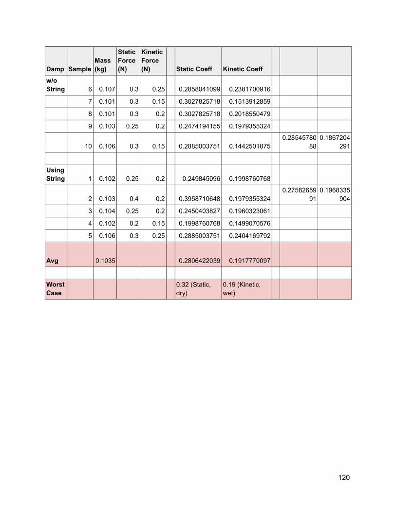
120
Damp Sample
Mass
(kg)
Static
Force
(N)
Kinetic
Force
(N) Static Coeff Kinetic Coeff
w/o
String 6 0.107 0.3 0.25 0.2858041099 0.2381700916
7 0.101 0.3 0.15 0.3027825718 0.1513912859
8 0.101 0.3 0.2 0.3027825718 0.2018550479
9 0.103 0.25 0.2 0.2474194155 0.1979355324
10 0.106 0.3 0.15 0.2885003751 0.1442501875 0.28545780
88
0.1867204
291
Using
String 1 0.102 0.25 0.2 0.249845096 0.1998760768
2 0.103 0.4 0.2 0.3958710648 0.1979355324 0.27582659
91
0.1968335
904
3 0.104 0.25 0.2 0.2450403827 0.1960323061
4 0.102 0.2 0.15 0.1998760768 0.1499070576
5 0.106 0.3 0.25 0.2885003751 0.2404169792
Avg 0.1035 0.2806422039 0.1917770097
Worst
Case 0.32 (Static,
dry)
0.19 (Kinetic,
wet)