Embed Size (px)
Citation preview
Advanced Ideas and Examples• Defining buckling modes• Why define buckling modes?• Understanding higher modes• Utilizing higher modes• Handling Indistinct modes• Solution Accuracy
CUFSM3.12CUFSM3.12
Defining Buckling Modes• For the majority of open-section thin-walled members the
relevant buckling modes can be broken into 3 groups:– Local – Distortional– Long
• Defining these buckling modes relies on an understanding of the role of the buckling– mode (shape), and– half-wavelengthfor models of members with sharp corners the new features of
cFSM also provide a means to formally define the buckling modes.
LocalLocal BucklingHalf-Wavelength
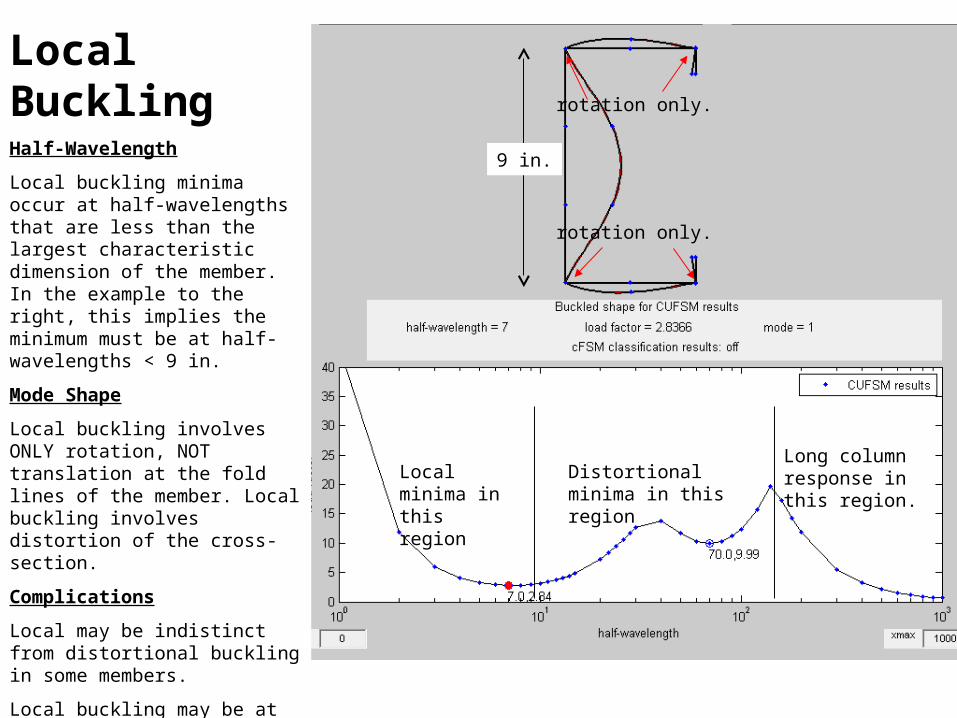
Local buckling minima occur at half-wavelengths that are less than the largest characteristic dimension of the member. In the example to the right, this implies the minimum must be at half-wavelengths < 9 in.
Mode Shape
Local buckling involves ONLY rotation, NOT translation at the fold lines of the member. Local buckling involves distortion of the cross-section.
Complications
Local may be indistinct from distortional buckling in some members.
Local buckling may be at half-wavelengths much less than the characteristic dimension if intermediate stiffeners are in place, or if the element undergoes large tension and small compressive stress.
9 in.
Local minima in this region
Distortional minima in this region
Long column response in this region.
rotation only.
rotation only.
Local buckling half-wavelength criteria• Local buckling of a simply supported plate in pure
compression occurs in square waves, i.e., it has a half-wavelength that is equal to the plate width.
• If any stress gradient exists on the plate, or any beneficial restraint is provided to the edges of the plate, the critical half-wavelength (mode 1 minimum) will be at a half-wavelength less than the plate width.
• Therefore, local buckling, with the potential for stable post-buckling response, is assumed to occur only when the critical half-wavelength is less than the largest potential “plate” in a member. If the half-wavelength is longer - the mode is not local buckling.
DistortionalDistortionalHalf-Wavelength
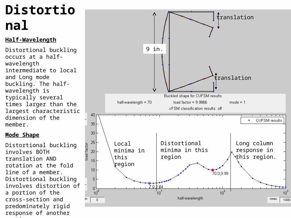
Distortional buckling occurs at a half-wavelength intermediate to local and Long mode buckling. The half-wavelength is typically several times larger than the largest characteristic dimension of the member.
Mode Shape
Distortional buckling involves BOTH translation AND rotation at the fold line of a member. Distortional buckling involves distortion of a portion of the cross-section and predominately rigid response of another portion.
Complications
Distortional buckling may be indistinct (without a minimum) even when local buckling and long half-wavelength buckling are clear.
The half-wavelength for distortional buckling is highly dependent on the loading and the geometry.
9 in.
Local minima in this region
Distortional minima in this region
Long column response in this region.
translation
translation
LongLong / “Euler”Half-Wavelength
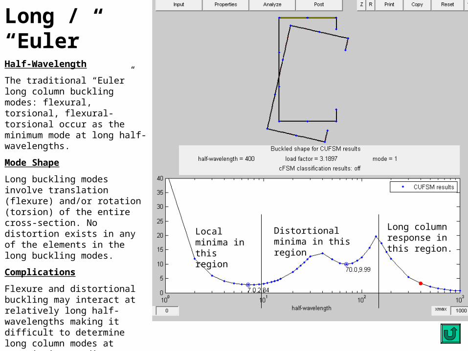
The traditional “Euler” long column buckling modes: flexural, torsional, flexural-torsional occur as the minimum mode at long half-wavelengths.
Mode Shape
Long buckling modes involve translation (flexure) and/or rotation (torsion) of the entire cross-section. No distortion exists in any of the elements in the long buckling modes.
Complications
Flexure and distortional buckling may interact at relatively long half- wavelengths making it difficult to determine long column modes at certain intermediate to long lengths.
Finite strip analysis assumes simply supported ends. When long column end conditions are not simply supported, or when they are dissimilar for flexure and torsion, higher modes may need to be considered, or classical long column calculations performed.
Local minima in this region
Distortional minima in this region
Long column response in this region.
Why define buckling modes?• CUFSM and the finite strip analysis provide only the
elastic critical response of a member• elastic critical buckling is a good input for design, but it
is not the design itself - thin-walled members have important post-buckling behavior that is not considered in this elastic buckling analysis
• Engineers have found that different failure characteristics and strength exist in the different buckling modes - thus design rules have been developed that are unique for each mode. To use these design rules the different definitions of the elastic buckling modes are necessary.
Understanding Higher Modes• Consider classic long column bucking. For thin-walled
members this generally includes the possibility of flexure (weak and strong direction), torsion, and flexural-torsional buckling
• Assume for a given unbraced length that flexural-torsional buckling has the lowest stress, i.e., it is the 1st mode. This implies that the other modes are higher modes: the 2nd, the 3rd and so on.
• Now, if long column buckling has a 2nd (and a 3rd) mode then it should stand to reason that local and distortional buckling have higher modes as well. In fact many higher modes exist and can be viewed using CUFSM.
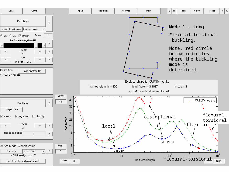
Mode 1 - LongMode 1 - Long
Flexural-torsional buckling.
Note, red circle below indicates where the buckling mode is determined.
flexural-torsional
flexural
flexural-torsional 2
distortional
local
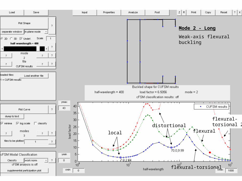
Mode 2 - LongMode 2 - Long
Weak-axis flexural buckling
flexural-torsional
flexural
flexural-torsional 2distortional
local
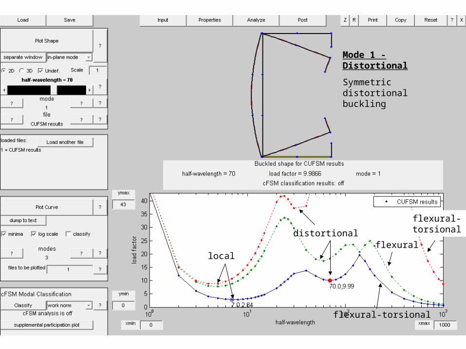
Mode 1 - DistortionalMode 1 - Distortional
Symmetric distortional buckling
flexural-torsional
flexural
flexural-torsional 2distortional
local
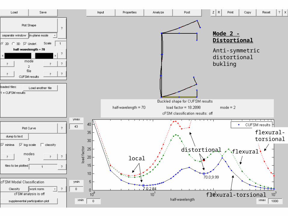
Mode 2 - DistortionalMode 2 - Distortional
Anti-symmetric distortional bukling
flexural-torsional
flexural
flexural-torsional 2
distortional
local

Mode 1 - LocalMode 1 - Local
Local buckling
flexural-torsional
flexural
flexural-torsional 2
distortional
local
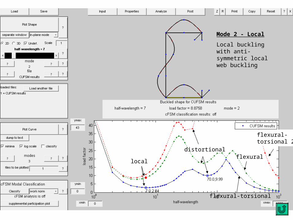
Mode 2 - LocalMode 2 - Local
Local buckling with anti-symmetric local web buckling
flexural-torsional
flexural
flexural-torsional 2
distortional
local
Utilizing Higher Modes• Knowledge of higher mode response benefits
– Long column buckling determination when effective length (KL) is different for different buckling modes
– examination of indistinct buckling modes and understanding of switching between buckling modes as a function of half-wavelength
– determination of member response if restraints were in place (e.g., connecting the lips of the members would change distortional buckling to anti-symmetric distortional buckling)
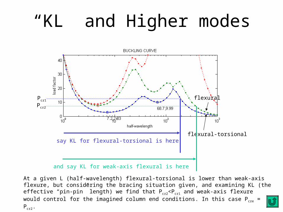
“KL” and Higher modes
flexural-torsional
flexural
say KL for flexural-torsional is here
and say KL for weak-axis flexural is here
Pcr1
Pcr2
At a given L (half-wavelength) flexural-torsional is lower than weak-axis flexure, but considering the bracing situation given, and examining KL (the effective “pin-pin” length) we find that P cr2<Pcr1 and weak-axis flexure would control for the imagined column end conditions. In this case Pcre = Pcr2.
Handling Indistinct Modes• Examples
– Local and distortional combine– No distinct distortional mode
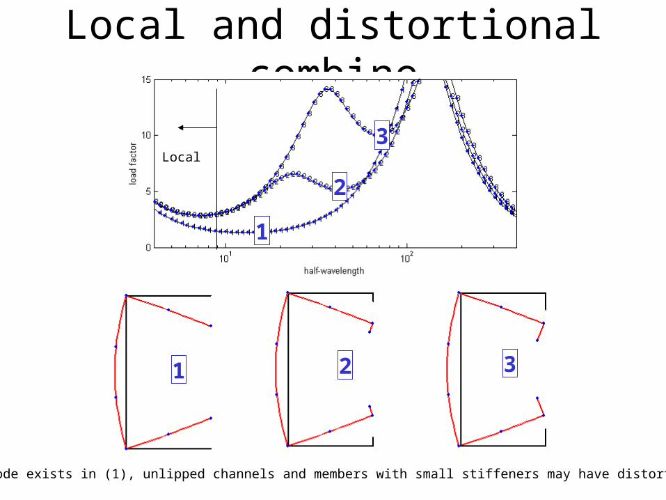
Local and distortional combine
1
2
3
1 2 3
No local mode exists in (1), unlipped channels and members with small stiffeners may have distortional only!
Local
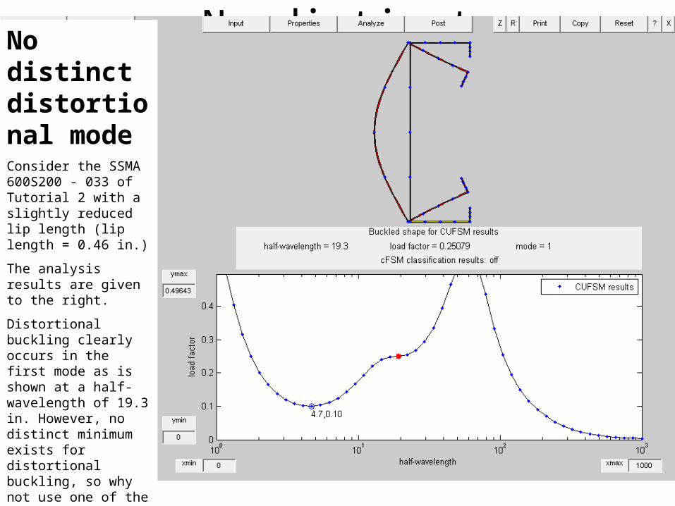
No distinct distortional modeNo distinct distortional modeConsider the SSMA 600S200 - 033 of Tutorial 2 with a slightly reduced lip length (lip length = 0.46 in.)
The analysis results are given to the right.
Distortional buckling clearly occurs in the first mode as is shown at a half-wavelength of 19.3 in. However, no distinct minimum exists for distortional buckling, so why not use one of the lower values to the left?
How can one determine where local buckling ends and distortional buckling begins in this case?
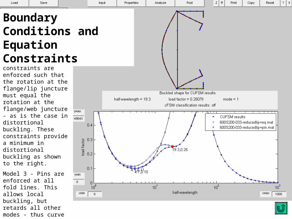
No distinct distortional modeModel 1 - Base model
Model 2 - Equation constraints are enforced such that the rotation at the flange/lip juncture must equal the rotation at the flange/web juncture - as is the case in distortional buckling. These constraints provide a minimum in distortional buckling as shown to the right.
Model 3 - Pins are enforced at all fold lines. This allows local buckling, but retards all other modes - thus curve 3 uniquely describes local buckling.
The minimum bounding curves of 2 and 3 provide distinct boundaries between local buckling and distortional buckling of the member.
Boundary Conditions and Equation Constraints
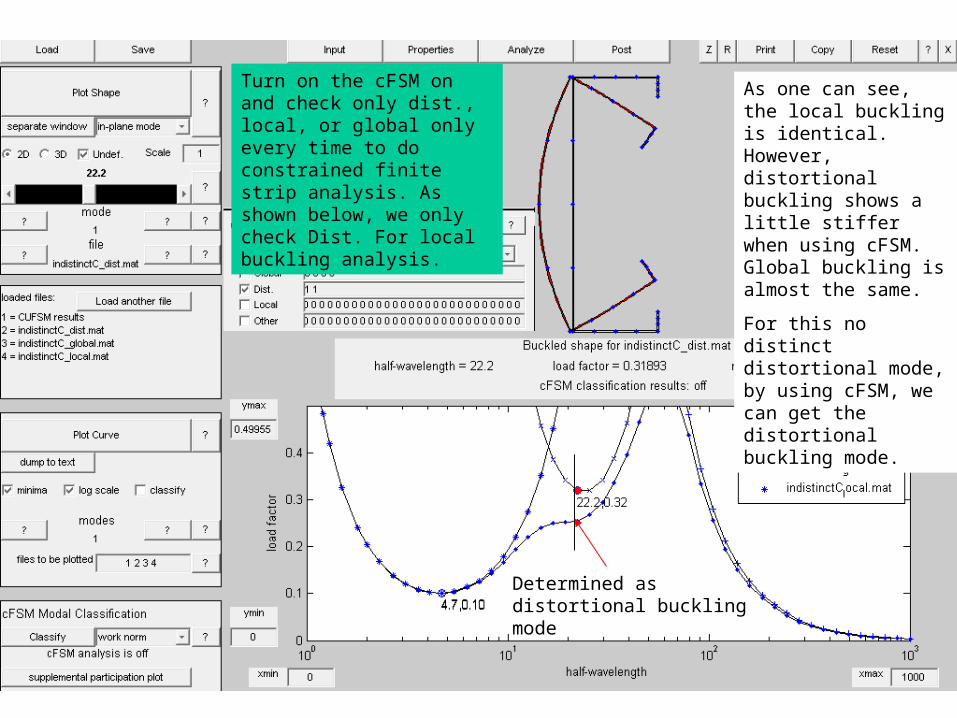
Turn on the cFSM on and check only dist., local, or global only every time to do constrained finite strip analysis. As shown below, we only check Dist. For local buckling analysis.
As one can see, the local buckling is identical. However, distortional buckling shows a little stiffer when using cFSM. Global buckling is almost the same.
For this no distinct distortional mode, by using cFSM, we can get the distortional buckling mode.
Determined as distortional buckling mode
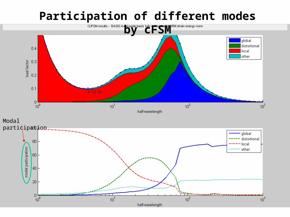
Participation of different modes by cFSM
Modal participation
Solution Accuracy• Number of elements• Number of lengths
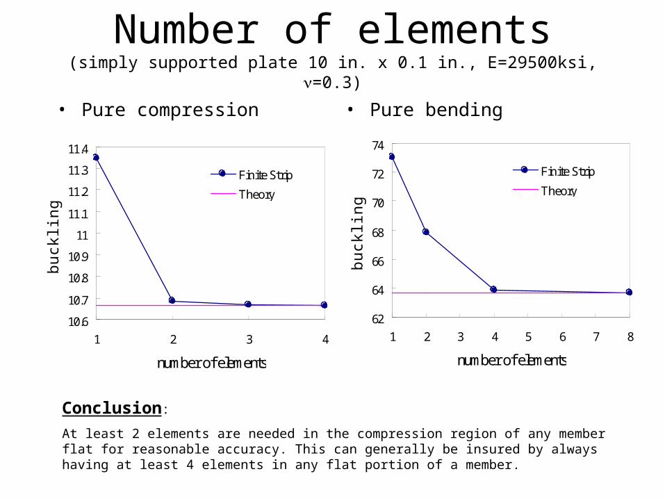
Number of elements(simply supported plate 10 in. x 0.1 in., E=29500ksi, =0.3)
• Pure compression • Pure bending
10.6
10.7
10.8
10.9
11
11.1
11.2
11.3
11.4
1 2 3 4
number of elements
buck
ling
stre
ss
Finite Strip
Theory
62
64
66
68
70
72
74
1 2 3 4 5 6 7 8
number of elementsbu
cklin
g st
ress
Finite Strip
Theory
Conclusion:
At least 2 elements are needed in the compression region of any member flat for reasonable accuracy. This can generally be insured by always having at least 4 elements in any flat portion of a member.
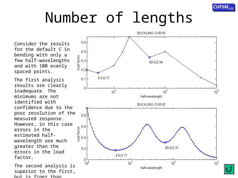
Number of lengths
Consider the results for the default C in bending with only a few half-wavelengths and with 100 evenly spaced points.
The first analysis results are clearly inadequate. The minimums are not identified with confidence due to the poor resolution of the measured response. However, in this case errors in the estimated half-wavelength are much greater than the errors in the load factor.
The second analysis is superior to the first, but is finer than required. Since the minimums are of primary interest an efficient analysis will use more half-wavelengths near these areas.
CUFSM3.12CUFSM3.12


![Impact and Postbuckling Analyses - imechanicaPostbuckling Analyses Geometric Imperfections for Postbuckling Analyses • Using buckling modes for imperfections]..](https://img.pdfslide.us/doc/110x75/5e279cdbcab01659037bd7a7/impact-and-postbuckling-analyses-imechanica-postbuckling-analyses-geometric-imperfections.jpg)