Embed Size (px)
Citation preview
32 NSC May 2008
Technical
The development of the new Blue Book on member resistances highlighted some new methods. Edurne Nunez
Moreno of the SCI explains the background to two of the issues.
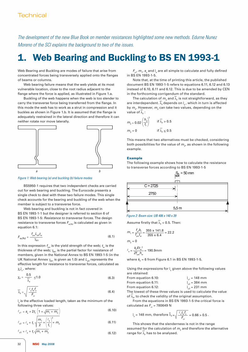
Web Bearing and Buckling are modes of failure that arise from concentrated forces being transversely applied onto the flanges of beams or columns. Web bearing failure means that the web yields at its most vulnerable location, close to the root radius adjacent to the flange where the force is applied, as illustrated in Figure 1.a. Buckling of the web happens when the web is too slender to carry the transverse force being transferred from the flange. In this mode the web has to work as a strut in compression and it buckles as shown in Figure 1.b. It is assumed that the flange is adequately restrained in the lateral direction and therefore it can neither rotate nor move laterally.
BS5950-1 requires that two independent checks are carried out for web bearing and buckling. The Eurocode presents a single check to deal with these two failure modes. This single check accounts for the bearing and buckling of the web when the member is subject to a transverse force. Web bearing and buckling is not in fact covered in BS EN 1993-1-1 but the designer is referred to section 6 of BS EN 1993-1-5: Resistance to transverse forces. The design resistance to transverse forces Fw,Rd is calculated as given in equation 6.1:
(6.1)F =fywLefftw
w,Rd γM1
In this expression fyw is the yield strength of the web; tw is the thickness of the web; γM1 is the partial factor for resistance of members, given in the National Annex to BS EN 1993-1-5 (in the UK National Annex γM1 is given as 1.0) and Leff represents the effective length for resistance to transverse forces, calculated as cFly , where:
(6.3)χF =0.5
λF
<1.0
(6.4)=lytwfyλF Fcr
ly is the effective loaded length, taken as the minimum of the following three values: (6.10)=ly1 ss + 2tf 1 + m1 + m2( )
(6.11)=ly2 le + tf (m1
2+ m2+
le
tf)
2
=ly3 le + tf m1 + m2 (6.12)
Fcr, m1, ss and le are all simple to calculate and fully defined in BS EN 1993-1-5. Note that, at the time of printing this article, the published document BS EN 1993-1-5 refers to equations 6.11, 6.12 and 6.13 instead of 6.10, 6.11 and 6.12. This is due to be amended by CEN in the forthcoming corrigendum of the standard. The calculation of m2 and lF is not straightforward, as they are interdependent. lF depends on ly , which in turn is affected by m2. However, m2 can take two values, depending on the value of lF :
if lF > 0.5=m2 0.02hw
tf( )
2
m2 = 0 if lF < 0.5
This means that two alternatives must be checked, considering both possibilities for the value of m2, as shown in the following example.
ExampleThe following example shows how to calculate the resistance to transverse forces according to BS EN 1993-1-5
Assume firstly that lF < 0.5. Then:
=m1 =fyfbf
fywtw
355 x 141.8355 x 6.4
= 22.2
m2 = 0
=le
kFEtw2
2fywhw
= 190.9mm
where kF = 6 from Figure 6.1 in BS EN 1993-1-5.
Using the expressions for ly given above the following values are obtained:From equation 6.10: ly1 = 148 mmFrom equation 6.11: ly2 = 384 mmFrom equation 6.12: ly3 = 231 mmThe lowest of these three values is used to calculate the value of lF, to check the validity of the original assumption. From the equations in BS EN 1993-1-5 the critical force is calculated as Fcr = 780649 N
ly = 148 mm, therefore =λF
lytwfy
Fcr
= 0.66 > 0.5 .
This shows that the slenderness is not in the range assumed for the calculation of m2 and therefore the alternative range for lF has to be analysed.
1. WebBearingandBucklingtoBSEN1993-1
Figure 1: Web bearing (a) and buckling (b) failure modes
Figure 2: Beam size: UB 406 x 140 x 39
a b

34 NSC May 2008
Try with lF > 0.5. Then:
m1 = 22.2, as per the first calculation
= 0.02m2
hw
tf
= 39.2( ) = 0.02 380.88.6( )
22
=le
kFEtw2
2fywhw
= 190.9mm
where kF = 6 from Figure 6.1 in BS EN 1993-1-5.
Using the expressions for ly given above:From equation 6.10: ly1 = 202 mmFrom equation 6.11: ly2 = 389 mmFrom equation 6.12: ly3 = 258 mmThe lowest of these three values is used to calculate the value of lF .
As in the previous case the critical force is calculated as Fcr = 780649 N from the equations in BS EN 1993-1-5.
ly = 202 mm, therefore =lytwfyλF Fcr
= 0.77 > 0.5. This shows
that the slenderness is in the range assumed for the calculation of m2 and therefore the calculation can be finalised using this value:
=χF0.5λF
=
fywLefftw
γM1
0.50.77
= 0.65 < 1.0
= χFly = 0.65 x 202 = 131mmLeff
∴Fw,Rd = = 355 x 131 x 641.0
x 10-3 = 298kN
This value compares with 327 kN for web bearing and 202 kN for web buckling calculated in accordance to BS5950-1.
Technical
2. Bucklingmodesofangles andchannelsincompressionTorsional buckling modes affect sections like angles, channels and cruciform sections in compression and can be critical in I sections when the flanges are not equally restrained. Clause 6.3.1.4 of BS EN 1993-1-1: 2005 requires torsional modes to be checked. For angles in compression the following buckling modes should be considered:
• Flexuralbucklingaboutthey-y,z-z,v-vandu-uaxis• Torsional-flexuralbuckling• Torsionalbuckling.
Clauses 6.3.1.3 and 6.3.1.4 of BS EN 1993-1-1 provide guidance to calculate slenderness for the buckling resistance for all of these modes.
• Slendernessforflexuralbuckling:
=AfyλNcr
=Lcr
i
1
λ1
, for class 3 angles (6.50)
=
AefffyλNcr
=Lcr
i λ1
Aeff
A for class 4 angles (6.51)
where = 93.9235
λ1 fy
These expressions are straightforward. Ncr is more commonly known as the Euler buckling load, or alternatively the slenderness can be calculated as the BS 5950 slenderness divided by a
constant. Note that = i
Lcr
ryy
Le and l1 is a constant, which
depends on the yield strength.• Slendernessfortorsional-flexuralbucklingandtorsional
buckling (one single check):
=AfyλT Ncr
for class 3 angles (6.52)
=AefffyλT Ncr
for class 4 angles (6.53)
where Ncr = min(Ncr,TF ; Ncr,T)
To avoid the complex iterative procedure to calculate Ncr,TF ,
Annex BB of BS EN 1993-1-1 allows an alternative approach which accounts for the practical types of end connections, which increase the member resistance. Annex BB gives the following modified expressions for the effective flexural slenderness:
leff,v = 0.35 + 0.7lv for buckling about the v-v axis leff,y = 0.50 + 0.7ly for buckling about the y-y axis leff,z = 0.50 + 0.7lz forbucklingaboutthez-zaxis
In these expressions lv, ly and lz are the values obtained from equations 6.50 or 6.51 as appropriate. These effective values of the flexural slenderness account for both flexural and torsional-flexural buckling in a much simpler way than by calculating Ncr,TF . These expressions are applicable provided the angles are appropriately restrained at the ends (at least two bolts if bolted, or welded). The code does not include an expression for the effective slenderness for buckling about the u-u axis. One could think that in some situations, when the angle is restrained about the v-v axis buckling about the u-u axis could be critical. However practical restraints against v-v buckling will also increase the torsional flexural resistance in the u-u axis. The torsional buckling resistance is not covered by the effective slenderness approach and must be calculated using Ncr,T . Torsional buckling resistances are given in the new Blue Book. Channels in compression are also affected by all these buckling modes. Although the calculation of Ncr,TF and Ncr,T for channels is quite involved, it does not require iteration and therefore the torsional and the torsional-flexural buckling resistance can be calculated by using the minimum of Ncr,TF and Ncr,T in equation 6.52 or 6.53. The flexural buckling resistance of channels is calculated using equation 6.50 or 6.51 for concentrically loaded channels and for channels connected only through its web when considering buckling about the major (y-y) axis. For channels connected only through its web when considering buckling about theminor(z-z)axisthefollowingexpressionfromAnnexBBisused for the effective slenderness: leff,z = 0.50 + 0.7lz
Continued on p 39 >

NSC May 2008 39
New and Revised Codes & Standards(from BSI Updates April 2008)
Codes & Standards
BRITISH STANDARDS UNDER REVIEW
BS EN 10056:- -Specification for structural steel equal and unequal angles BS EN 10056-1:1999 Dimensions
BS EN 10058:2003Hot rolled flat steel bars for general purposes. Dimensions and tolerances on shape and dimensions
BS EN 10059:2003Hot rolled square steel bars for general purposes. Dimensions and tolerances on shape and dimensions
BS EN 10060:2003Hot rolled round steel bars for general purposes. Dimensions and tolerances on shape and dimensions
BS EN 10061:2003Hot rolled hexagon steel bars for general purposes. Dimensions and tolerances on shape and dimensions
DRAFT BRITISH STANDARDS FOR PUBLIC COMMENT
08/30128144 DCBS EN 1993-1-11 UK National Annex to Eurocode 3. Design of steel structures.Part 1-11. Design of structures with tension components
ISO PUBLICATIONS
ISO 13918:2008(Edition 2)Welding. Studs and ceramic ferrules for arc stud weldingWill be implemented as an identical British Standard.
In this expression lz is calculated as given in 6.50 or 6.51. This expression is applicable provided the channel is appropriately restrained at the ends (at least two bolts if bolted, or welded). In any other case provision for the eccentricity must be made by following the rules for combined bending and axial force, given in clause 6.2.9 of BS EN 1993-1-1. The new Blue Book to the Eurocodes follows this approach when calculating the resistance of angles and channels. Future articles will cover the contents of the publication, and how the design data is to be used.
Technical
Buckling modes of angles and channels in compressionContinued from p34
Capability. Innovation. Knowledge. It’s strengths like these
that make Richard Lees Steel Decking such a powerful choice.
And enable us to create such a positive, dependable
difference to your structural flooring projects. For more
products, more experience and more reassurance, talk to
Richard Lees Steel Decking. It’s everything you need.
Trust is everything
www.rlsd.com
Richard Lees Steel Decking LtdMoor Farm Road West, The Airfield, Ashbourne, Derbyshire DE6 1HD, UK.Tel: +44 (0) 1335 300 999 | Fax: +44 (0) 1335 300 888Email: [email protected]
• 60+ years’ experience supplying
structural flooring products
• A reputation for industry ‘firsts’
• Proven on some of the world’s
most prestigious projects


![[N. S. Trahair]Flexural-Torsional Buckling of Strorg)](https://img.pdfslide.us/doc/110x75/55cf8e61550346703b919745/n-s-trahairflexural-torsional-buckling-of-strorg.jpg)