Embed Size (px)
Citation preview
Advance Design – Bracing members design according to Eurocode 3 Author: Eng. Victor Seiculescu∗, PhD student
Advance Design was specifically developed for industry professionals that require a superior solution for the structural analysis and design of Reinforced Concrete and Steel structures according to the latest versions of Eurocodes (EC0, EC1, EC2, EC3 and EC8).
Advance Design features include easy modeling, a powerful FEM analysis engine, top-level design wizards, automated post-processing of results and automated reports. Achieve a new level of computer-assisted engineering with Advance Design!
The goal of this article is to present the efficiency of automatic calculus (done with Advance Design) instead of manual calculus for verifying the bracing members against buckling. Automatic calculus is done for a multi-story steel concentrically braced frame building subjected to seismic action according to Romanian Seismic Code (P100-1/2006). In this structure the most solicited bracing member is studied. The verification results obtained through automatic calculus are in good agreement with manual calculus.
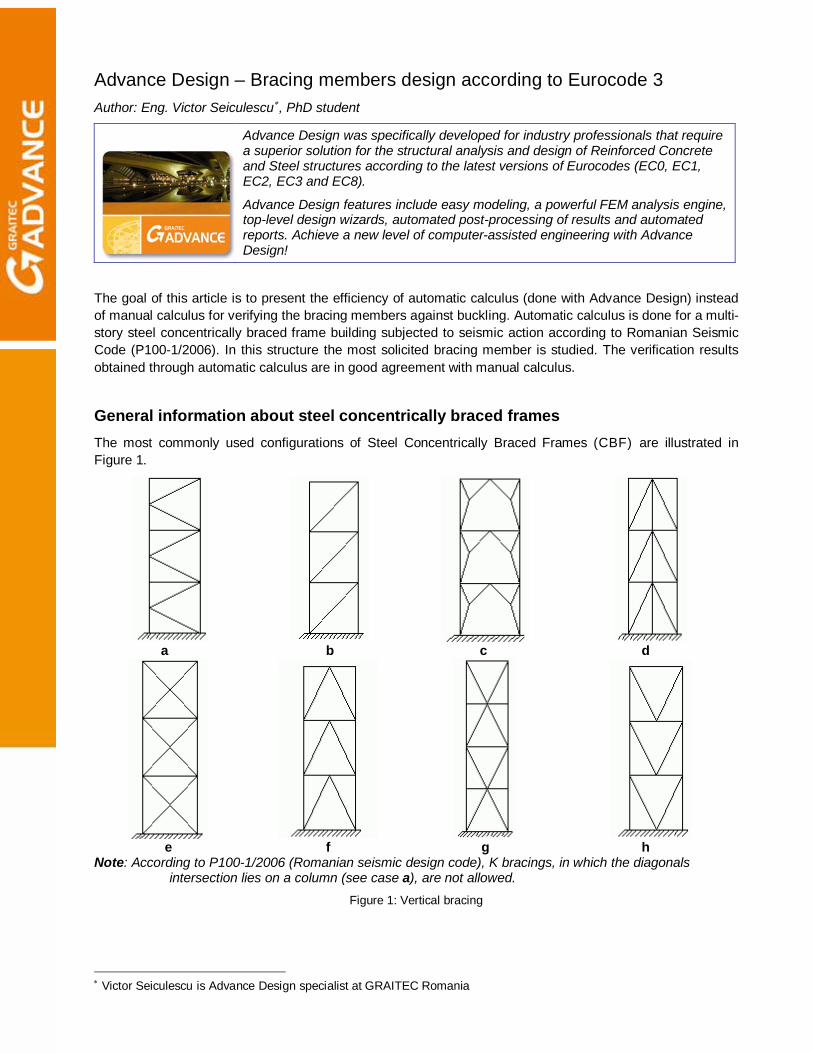
General information about steel concentrically braced frames The most commonly used configurations of Steel Concentrically Braced Frames (CBF) are illustrated in Figure 1.
a b c d
e f g h
Note: According to P100-1/2006 (Romanian seismic design code), K bracings, in which the diagonals intersection lies on a column (see case a), are not allowed.
Figure 1: Vertical bracing
∗ Victor Seiculescu is Advance Design specialist at GRAITEC Romania
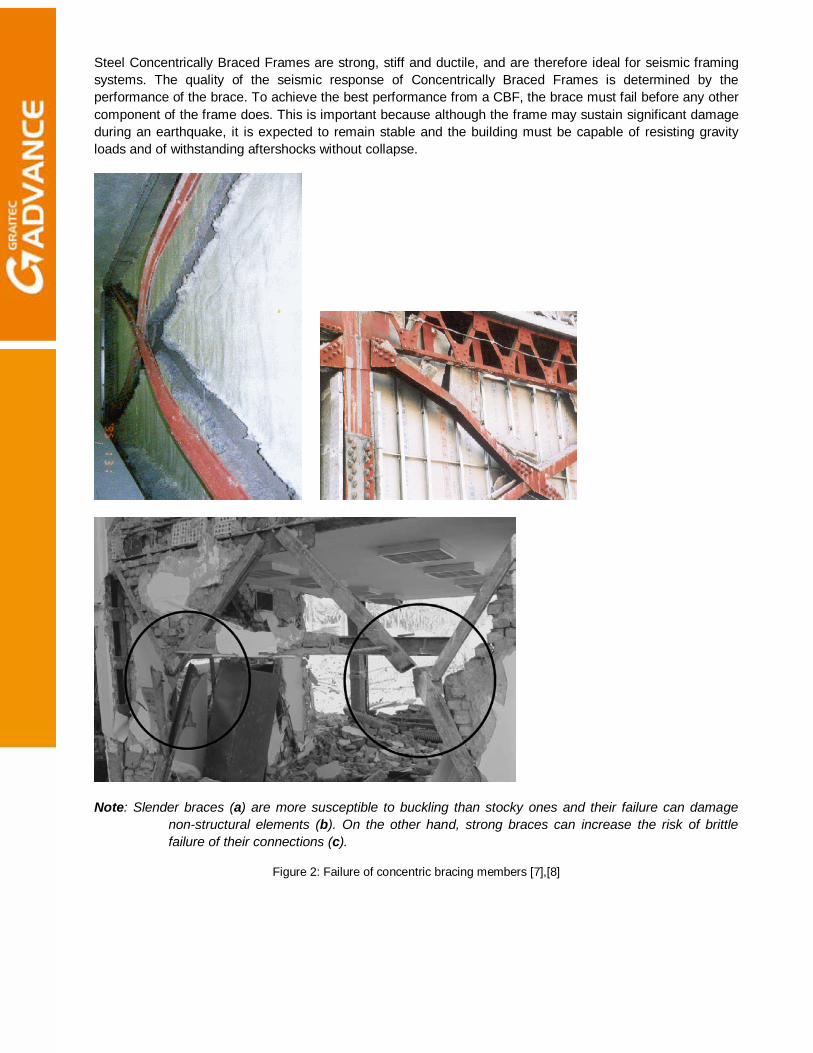
Steel Concentrically Braced Frames are strong, stiff and ductile, and are therefore ideal for seismic framing systems. The quality of the seismic response of Concentrically Braced Frames is determined by the performance of the brace. To achieve the best performance from a CBF, the brace must fail before any other component of the frame does. This is important because although the frame may sustain significant damage during an earthquake, it is expected to remain stable and the building must be capable of resisting gravity loads and of withstanding aftershocks without collapse.
Note: Slender braces (a) are more susceptible to buckling than stocky ones and their failure can damage
non-structural elements (b). On the other hand, strong braces can increase the risk of brittle failure of their connections (c).
Figure 2: Failure of concentric bracing members [7],[8]

Cyclic testing of conventional braced frames, done by Nathan Canney at Seattle University, showed that these braces buckle in compression and yield in tension. He showed the following inelastic behavior of bracing member:
- Plastic hinges occur after the brace has buckled and the stiffness and resistance of the frame decreases, illustrated in Figure 3;
- In Zone 0-A, the frame retains its elasticity, but the brace buckles at A, causing a plastic hinge to form in Zone A-B;
- Load reversal in Zones B-C, C-D and D-E cause the brace to become unstable, decreasing the effectiveness of the frame. This unstable behavior is evident in the unsymmetrical response seen in Figure 3a. For this reason, Concentrically Braced Frames (CBFs), with braces in opposing pairs, are used given the stable inelastic performance seen in Figure 3c.
Figure 3: Behavior of Concentrically Braced Frames [1]
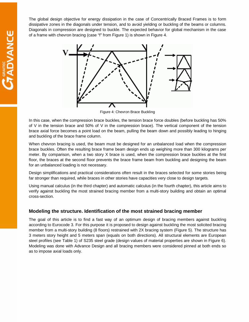
The global design objective for energy dissipation in the case of Concentrically Braced Frames is to form dissipative zones in the diagonals under tension, and to avoid yielding or buckling of the beams or columns. Diagonals in compression are designed to buckle. The expected behavior for global mechanism in the case of a frame with chevron bracing (case “f” from Figure 1) is shown in Figure 4.
Figure 4: Chevron Brace Buckling
In this case, when the compression brace buckles, the tension brace force doubles (before buckling has 50% of V in the tension brace and 50% of V in the compression brace). The vertical component of the tension brace axial force becomes a point load on the beam, pulling the beam down and possibly leading to hinging and buckling of the brace frame column.
When chevron bracing is used, the beam must be designed for an unbalanced load when the compression brace buckles. Often the resulting brace frame beam design ends up weighing more than 300 kilograms per meter. By comparison, when a two story X brace is used, when the compression brace buckles at the first floor, the braces at the second floor prevents the brace frame beam from buckling and designing the beam for an unbalanced loading is not necessary.
Design simplifications and practical considerations often result in the braces selected for some stories being far stronger than required, while braces in other stories have capacities very close to design targets.
Using manual calculus (in the third chapter) and automatic calculus (in the fourth chapter), this article aims to verify against buckling the most strained bracing member from a multi-story building and obtain an optimal cross-section.
Modeling the structure. Identification of the most strained bracing member The goal of this article is to find a fast way of an optimum design of bracing members against buckling according to Eurocode 3. For this purpose it is proposed to design against buckling the most solicited bracing member from a multi-story building (8 floors) restrained with 2X bracing system (Figure 5). The structure has 3 meters story height and 5 meters span (equals on both directions). All structural elements are European steel profiles (see Table 1) of S235 steel grade (design values of material properties are shown in Figure 6). Modeling was done with Advance Design and all bracing members were considered pinned at both ends so as to impose axial loads only.
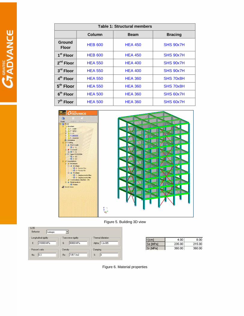
Table 1: Structural members
Column Beam Bracing
Ground Floor HEB 600 HEA 450 SHS 90x7H
1st Floor HEB 600 HEA 450 SHS 90x7H
2nd Floor HEA 550 HEA 400 SHS 90x7H
3rd Floor HEA 550 HEA 400 SHS 90x7H
4th Floor HEA 550 HEA 360 SHS 70x8H
5th Floor HEA 550 HEA 360 SHS 70x8H
6th Floor HEA 500 HEA 360 SHS 60x7H
7th Floor HEA 500 HEA 360 SHS 60x7H
Figure 5. Building 3D view
Figure 6. Material properties

The building is subjected to horizontal seismic action (elastic spectral analysis was applied considering elastic response spectrum for Vrancea region - severe seismic area with the design peak ground acceleration ag=0.32 g and control period Tc=1.6s ). According to P100-1/2006 elastic response spectrum for horizontal components of the field ground acceleration, is defined as below:
(relation 3.6 from P100-1/2006 [6])
where ag is the peak ground acceleration [m/s2].
Figure 7. Normalized elastic response spectrum for TC = 1.6s
Normalized elastic response spectrum, for fraction of critical damping and depending to control periods TB, TC, TD is states as follows:
where is the factor of maximum dynamic amplification of ground horizontal acceleration by the structure.
The loads applied to the structure include relevant load factors and load combination factors. The definition of load cases and load combinations is made as shown in Figure 8.
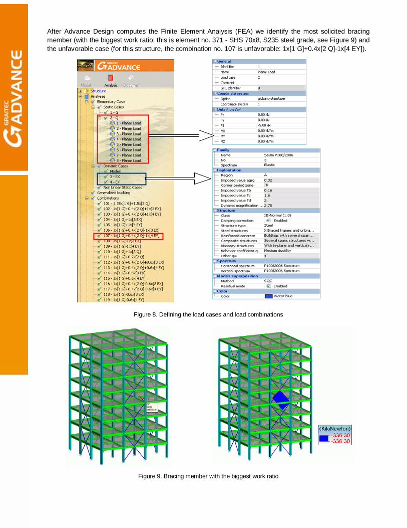
After Advance Design computes the Finite Element Analysis (FEA) we identify the most solicited bracing member (with the biggest work ratio; this is element no. 371 - SHS 70x8, S235 steel grade, see Figure 9) and the unfavorable case (for this structure, the combination no. 107 is unfavorable: 1x[1 G]+0.4x[2 Q]-1x[4 EY]).
Figure 8. Defining the load cases and load combinations
Figure 9. Bracing member with the biggest work ratio
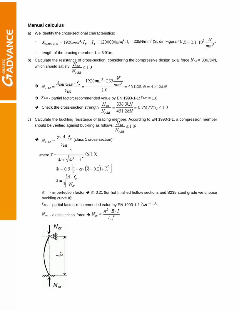
Manual calculus a) We identify the cross-sectional characteristics:
- ; ; fy = 235N/mm2 (Se din Figura 4); ;
- length of the bracing member: L = 3.91m;
b) Calculate the resistance of cross-section, considering the compressive design axial force NEd = 336.3kN, which should satisfy:
- partial factor; recommended value by EN 1993-1-1: = 1.0
Check the cross-section strength:
c) Calculate the buckling resistance of bracing member. According to EN 1993-1-1, a compression member should be verified against buckling as follows: ;
(class 1 cross-section);
where
α - imperfection factor α=0.21 (for hot finished hollow sections and S235 steel grade we choose buckling curve a);
- partial factor, recommended value by EN 1993-1-1: ;
- elastic critical force
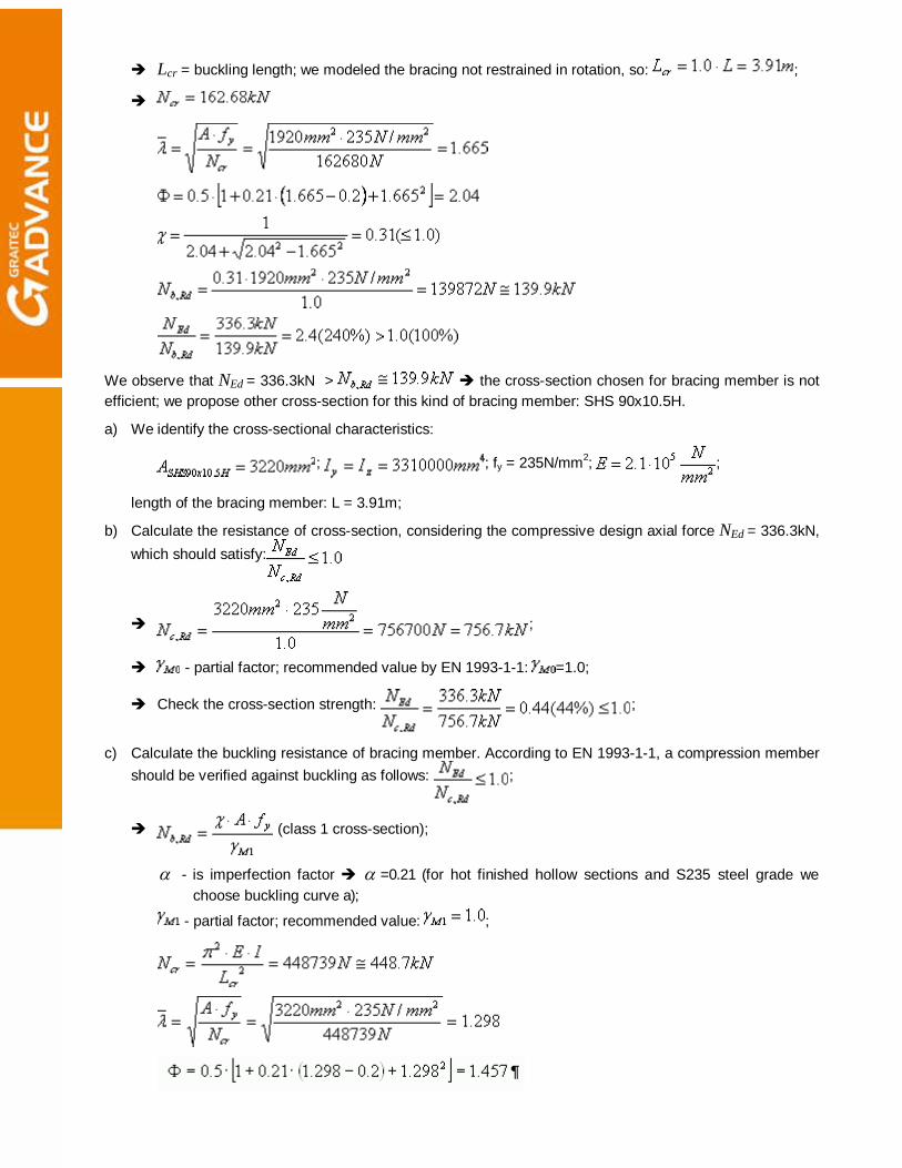
Lcr = buckling length; we modeled the bracing not restrained in rotation, so: ;
We observe that NEd = 336.3kN > the cross-section chosen for bracing member is not efficient; we propose other cross-section for this kind of bracing member: SHS 90x10.5H.
a) We identify the cross-sectional characteristics:
; ; fy = 235N/mm2; ;
length of the bracing member: L = 3.91m;
b) Calculate the resistance of cross-section, considering the compressive design axial force NEd = 336.3kN, which should satisfy:
;
- partial factor; recommended value by EN 1993-1-1: =1.0;
Check the cross-section strength: ;
c) Calculate the buckling resistance of bracing member. According to EN 1993-1-1, a compression member should be verified against buckling as follows: ;
(class 1 cross-section);
α - is imperfection factor α =0.21 (for hot finished hollow sections and S235 steel grade we choose buckling curve a);
- partial factor; recommended value: ;

We observe that NEd = 336.3kN < the proposed cross-section meets the requirement.
Note: Eurocode provides a more explicit relationship for members subjected to combined bending and axial compression; but the bracing members are not subjected to bending (My,Ed=0; Mz,Ed=0 ), therefore the 2nd and the 3rd terms of the relationships 6.61 and 6.62, from EN 1993-1-1, are neglected.
[relationship 6.61 from EN 1993-1-1]
[relationship 6.62 from EN 1993-1-1]
Results obtained with Advance Design. Conclusions The next step is to investigate the accuracy of manual made verifications; for this we shall use Steel Design module, part of Advance Design (AD), which will check if the bracing member has an optimal section according to Eurocode 3; furthermore it will check all structural elements for an optimal section, giving to user the possibility to obtain a fast designing and an economical structure.
After we have done the Steel Calculation (module of AD for calculating of steel elements), Advance Design offers the possibility to see the cross-section characteristics, the material used for analysis and the steel grade (Figure 10).
Figure 10. Selected cross section info
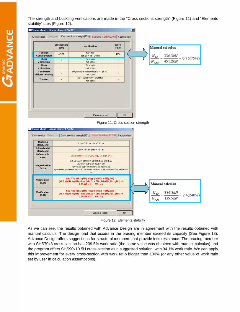
The strength and buckling verifications are made in the “Cross sections strength” (Figure 11) and “Elements stability” tabs (Figure 12).
Figure 11. Cross section strength
Figure 12. Elements stability
As we can see, the results obtained with Advance Design are in agreement with the results obtained with manual calculus. The design load that occurs in the bracing member exceed its capacity (See Figure 13). Advance Design offers suggestions for structural members that provide less resistance. The bracing member with SHS70x8 cross-section has 239.5% work ratio (the same value was obtained with manual calculus) and the program offers SHS90x10.5H cross-section as a suggested solution, with 94.1% work ratio. We can apply this improvement for every cross-section with work ratio bigger than 100% (or any other value of work ratio set by user in calculation assumptions).
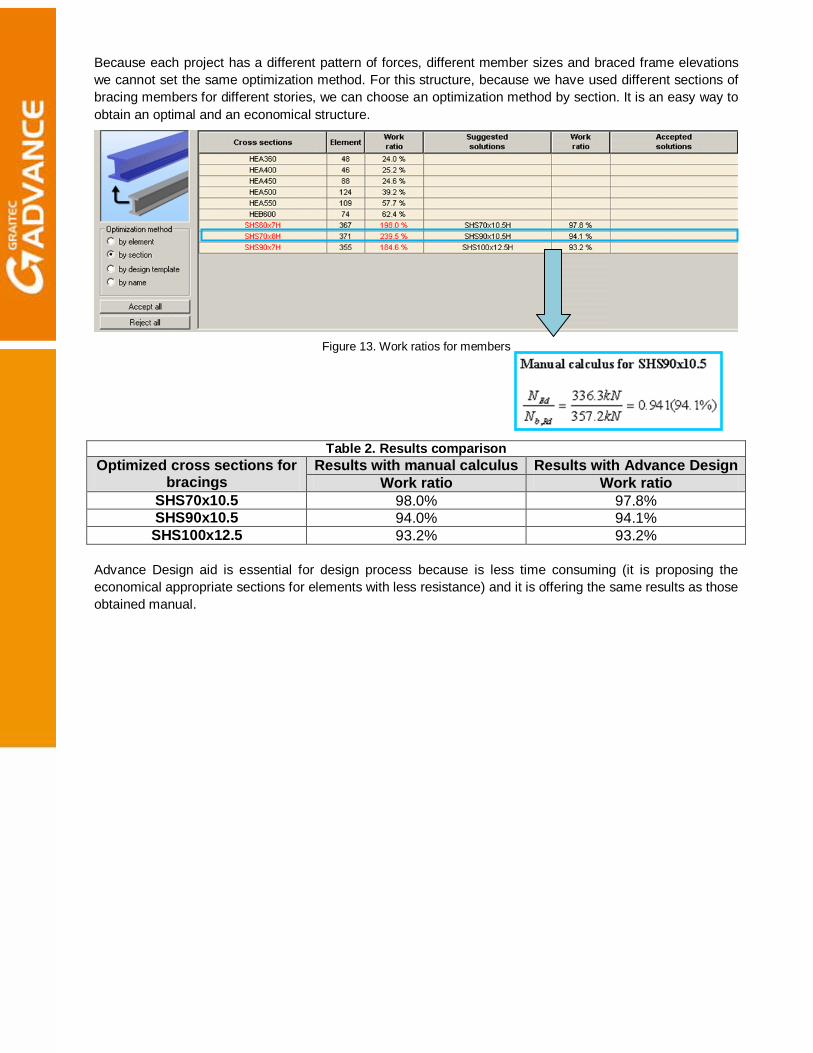
Because each project has a different pattern of forces, different member sizes and braced frame elevations we cannot set the same optimization method. For this structure, because we have used different sections of bracing members for different stories, we can choose an optimization method by section. It is an easy way to obtain an optimal and an economical structure.
Figure 13. Work ratios for members
Table 2. Results comparison Optimized cross sections for
bracings Results with manual calculus Results with Advance Design
Work ratio Work ratio SHS70x10.5 98.0% 97.8% SHS90x10.5 94.0% 94.1% SHS100x12.5 93.2% 93.2%
Advance Design aid is essential for design process because is less time consuming (it is proposing the economical appropriate sections for elements with less resistance) and it is offering the same results as those obtained manual.
References: 1. Canney, N., “Performance of concentrically braced frames under cyclic loading”, Seattle University ;
2. EN 1993-1-1 Design of steel structures – Part 1-1: General rules and rules for buildings, May 2005;
3. Stephen A. Mahin , Patxi Uriz ,University of California, Berkeley, CA USA, Seismic Performance Assessment of Special Concentrically Braced Steel Frames;
4. Wengshui Gan, December 1996, Pasadena California, Earthquake response of steel braces and braced steel frames;
5. Rafael Sabelli; Stephen Mahin; Chunho Chang; Seismic Demands on Steel Braced Frame Buildings with Buckling-Restrained Braces;
6. P100-1/2006; Cod de proiectare seismică - Partea I - Prevederi de proiectare pentru clădiri;
7. Seismic Connection Seminar: Detailing High Seismic Projects; American Institute of Steel Constructions;
8. http://www.emeraldinsight.com/fig/1100230302007.png.