Embed Size (px)
Citation preview

Permanent Bracing Design for
MPC Wood Roof Truss Webs and Chords
Catherine Richardson Underwood
Thesis submitted to the Faculty of the
Virginia Polytechnic Institute and State University
in partial fulfillment of the requirements for the degree of
Master of Science
in
Biological Systems Engineering
Frank E. Woeste, Chair
J. Daniel Dolan
Siegfried M. Holzer
March, 2000Blacksburg, Virginia
Keywords: Truss, Bracing, Wood, Roofs, Construction, Residential

Permanent Bracing Design for
MPC Wood Roof Truss Webs and Chords
Catherine Richardson Underwood
(ABSTRACT)
The objectives of this research were to determine the required net lateral restraining force
to brace j-webs or j-chords braced by one or more continuous lateral braces (CLB’s), and
to develop a methodology for permanent bracing design using a combination of lateral
and diagonal braces.
SAP2000 (CSI, 1995), a finite element analysis program, was used to analyze structural
analogs for three sets of truss chords braced by n-CLB’s and one or two diagonals, one
web braced by one and two CLB’s, and j-truss chords braced by n-CLB’s.
System analogs used to model five eight-foot truss chords braced by three CLB’s and one
diagonal, six twenty-foot truss chords braced by nine CLB’s and two diagonals, and
eleven twenty-foot truss chords braced by nine CLB’s and two diagonals were analyzed.
For each of the three cases analyzed, the chord lumber was assumed to be 2x4 No. 2
Southern Pine (S. Pine) braced by 2x4 STUD Spruce-Pine-Fir (SPF). Chord load levels
of 10% to 50% of the allowable compression load parallel-to-grain assuming le/d of 16
were studied. All wood-to-wood brace connections were assumed to be made with 2-16d
Common nails. A nonlinear load-displacement function was used to model the behavior
of the nail connections.
Single member analogs were analyzed that represented web members varying in length
from four-feet to twelve-feet braced by one and two CLB’s. The web and CLB’s were
assumed to be 2x4 STUD SPF. The web members were also analyzed assuming 2x6
STUD SPF.

iii
Single member analogs were analyzed that represented chord members varying in length
from four-feet to forty-feet braced by n-CLB’s spaced twenty-four inches on-center. The
truss chord was assumed to be No. 2 Southern Pine and the CLB’s were assumed to be
STUD SPF. The chord size was varied from 2x4 to 2x12 and connections were assumed
to consist of 2-16d Common nails. The system analog analysis results were compared to
the single member chord analysis results based on the number of truss chords and the
diagonal brace configuration.
For the three cases studied involving multiple 2x4 chords braced as a unit (and believed
to be representative of typical truss construction), the bracing force from the single
member analog analysis was a conservative estimate for bracing design purposes. It was
concluded that the single member analysis analog yields approximate bracing forces for
chords larger than 2x4 and for typical constructions beyond the three cases studied in this
research.
For analysis and design purposes, a ratio R was defined as the net lateral restraining force
per web or chord divided by the axial compressive load in the web or chord. For both
2x4 and 2x6 webs braced with one CLB, the R-value was 2.3% for all web lengths
studied. For both 2x4 and 2x6 webs braced with two CLB’s, the R-value was 2.8% for
all web lengths studied. The web and CLB lumber species did not affect the R-values for
the braced webs.
Calculated R-values for truss chords, 2x4 up to 2x12, braced by n-CLB’s assumed to be
spaced two feet on-center for chords four to twelve feet in length ranged from 2.2% to
3.0%, respectively. For chords from sixteen to forty feet in length, R ranged from 3.1%
to 2.6%, respectively. The lumber species and grade assumed for the chord and CLB did
not affect the R-values for the truss chords.
A step-by-step design procedure was developed for determining the net lateral restraining
force required for bracing j-chords based on the results of the single member analogs
studied. The required total lateral restraining force for j-compression members in a row

iv
can be calculated based on the R-value for or the number of CLB’s installed at 2 feet on-
center, the design axial compression load in the chord, and number of trusses to be
braced.

v
Acknowledgements
I would like to extend my thanks to Dr. Frank E. Woeste for his everlasting support and
confidence in me. I would like to thank Dr. Woeste and Dr. John Perumpral for the
financial support and guidance extended to me throughout my stay here at Virginia Tech.
In addition, I would like to thank Dr. Dan Dolan and Dr. Seigfried Holzer for serving as
my committee and helping me finalize this work.
Additionally, thanks:
To my husband, Casey, who has loved and supported me through it all.
To my father for his support and guidance all these years.
To my mother for her wisdom and excellence in everything she did.
To my brothers, David, John, and James for teaching me how to survive, even in the
tough times.

vi
Table of Contents
1. INTRODUCTION..................................................................................................... 1
OBJECTIVES ..................................................................................................................... 2
2. BACKGROUND AND LITERATURE REVIEW................................................. 7
2.1 TEMPORARY BRACING PRINCIPLES .......................................................................... 7
2.1.1 Triangle Theory............................................................................................... 7
2.1.2 Temporary Bracing Planes ........................................................................... 15
2.2 STABILITY.............................................................................................................. 15
2.3 BUCKLING AND BRACING....................................................................................... 17
2.4 TEMPORARY BRACING GUIDELINES AVAILABLE FROM THE INDUSTRY.................. 18
2.4.1 DSB-89 .......................................................................................................... 18
2.4.2 HIB-91 Pocketbook ....................................................................................... 22
2.4.3 HIB-91 Summary Sheet ................................................................................. 25
2.4.4 HIB-98 Post-Frame Summary Sheet............................................................. 25
2.4.5 Alpine/WTCA Video on Temporary Bracing ................................................ 26
2.5 OTHER DOCUMENTS PROVIDING GUIDELINES FOR TEMPORARY AND PERMANENT
BRACING........................................................................................................................ 26
2.5.1 LRFD Steel Approach ................................................................................... 27
2.5.2 South African Standard Code of Practice… ................................................. 28
2.5.3 Commentary for Permanent Bracing of Metal Plate Connected Wood Trusses
................................................................................................................................... 29

vii
2.6 PREVIOUS STUDIES ................................................................................................ 30
2.6.1 Background ................................................................................................... 30
2.6.1.1 Plaut’s Method .................................................................................................................................31
2.6.1.2 Winter’s method...............................................................................................................................32
2.6.1.3 Tsien’s method .................................................................................................................................34
2.6.1.4 2% Rule ...........................................................................................................................................34
2.6.2 Procedure...................................................................................................... 35
2.6.3 Testing........................................................................................................... 40
2.6.4 Results ........................................................................................................... 41
2.6.5 Performance Variables ................................................................................. 43
2.6.6 Conclusion .................................................................................................... 45
3. FINITE ELEMENT MODELING AND ANALYSIS ......................................... 46
3.1 GENERAL ASSUMPTIONS ........................................................................................ 46
3.2 DESIGN CONSIDERATIONS...................................................................................... 46
3.2.1 n-CLB’s ......................................................................................................... 46
3.2.2 One CLB........................................................................................................ 48
3.2.3. Two CLB’s..................................................................................................... 48
3.3 SAP2000 (CSI, 1995) ........................................................................................... 52
3.4 WALTZ’S STRUCTURAL ANALOG IN SAP2000 (CSI, 1995)................................... 53
3.5 SYSTEM ANALOGS ................................................................................................. 58
3.5.1 Five Chords Braced by Three CLB’s ............................................................ 58
3.5.2 Six Chords Braced by Nine CLB’s ................................................................ 66
3.5.3 Eleven Chords Braced by Nine CLB’s .......................................................... 69
3.6 SINGLE MEMBER ANALOGS ................................................................................... 74

viii
3.6.1 One Web braced by One CLB ....................................................................... 77
3.6.2 One Web Braced by Two CLB’s ................................................................... 77
3.6.3 Effects of Lumber Size................................................................................... 80
3.6.4 Effects of Lumber Specific Gravity and Modulus of Elasticity, E................. 80
3.6.5 Truss Chord Braced by n-CLB’s................................................................... 81
4. RESULTS ................................................................................................................ 88
4.1 FORCES REQUIRED TO BRACE SYSTEM ANALOGS.................................................. 88
4.1.1 Forces Required to Brace Eight Chords with Three CLB’s and One
Diagonal Brace ......................................................................................................... 88
4.1.2 Forces Required to Brace Six Chords with Nine CLB’s and Two Diagonals
……………………………………… ……………………………………..92
4.1.3 Forces Required to Brace Eleven Chords with Nine CLB’s and Two
Diagonals .................................................................................................................. 93
4.2 FORCES REQUIRED TO BRACE SINGLE MEMBER ANALOGS.................................... 94
4.2.1 Forces Required to Brace a Web with One CLB .......................................... 94
4.2.2 Forces Required to Brace a Web with Two CLB’s ....................................... 98
4.3 EFFECTS OF LUMBER SIZE...................................................................................... 98
4.4 EFFECTS OF LUMBER SPECIFIC GRAVITY AND MODULUS OF ELASTICITY, E ....... 102
4.5 FORCE REQUIRED TO BRACE A CHORD WITH N-CLB’S........................................ 103
4.6 PROPOSED DESIGN PROCEDURE........................................................................... 117
4.6.1 Case I – One diagonal brace ...................................................................... 117
4.6.2 Case II – Two diagonal braces in a V-shape .............................................. 119
4.7 SYSTEM VERSUS SINGLE MEMBER ANALOGS...................................................... 121

ix
4.7.1 Comparison of Required NL for Five Eight-foot Truss Chords.................. 122
4.7.2 Comparison of Required NL for Six Twenty-foot Truss Chords................. 124
4.7.3 Comparison of Required NL for Eleven Twenty-foot Truss Chords........... 124
5.0 CONCLUSIONS ................................................................................................... 128
5.1 SYSTEM AND SINGLE MEMBER ANALOGS............................................................ 128
5.2 ONE WEB BRACED WITH ONE CLB ..................................................................... 129
5.3 ONE WEB BRACED WITH TWO CLB’S .................................................................. 130
5.4 ROOF TRUSS CHORD BRACED BY N-CLB’S .......................................................... 131
REFERENCES.............................................................................................................. 133
APPENDIX A ................................................................................................................ 136
SAMPLE CALCULATIONS TO DETERMINE FC’ FOR USE IN SAP2000 (CSI, 1995) ANALYSIS
..................................................................................................................................... 136
APPENDIX B ................................................................................................................ 138
SPRING FORCES PRODUCED IN THE CHORD AND CLB NAIL CONNECTIONS IN SAP2000
(CSI, 1995) FOR SOUTHERN PINE CHORDS BRACED BY N-SPRUCE-PINE-FIR WEBS FOR A
SINGLE MEMBER ANALYSIS .......................................................................................... 138
APPENDIX C ................................................................................................................ 150
SPRING FORCES PRODUCED IN THE CHORD AND DIAGONAL NAIL CONNECTIONS FOR A
SYSTEM ANALYSIS IN SAP2000 (CSI, 1995) FOR SOUTHERN PINE CHORDS BRACED BY
N-SPRUCE-PINE-FIR WEBS AND ONE OR TWO SPRUCE-PINE-FIR DIAGONALS ............... 150
VITA............................................................................................................................... 151
x
List of Figures
Figure 1.1. j-truss webs are braced with one CLB and one diagonal that crosses the trusswebs. ........................................................................................................... 3
Figure 1. 2. j-truss chords are braced using one diagonal that crosses trusses. ................ 4
Figure 1. 3. j-truss chords are braced with two diagonals in a V-shape ........................... 5
Figure 2.1. (a) A square is structurally unstable................................................................ 8
(b) When a force is applied, a square will distort. .......................................... 8
(c) A member can be added to form two interrelated triangles, which arestructurally stable. ....................................................................................... 8
Figure 2.2. Assuming perfectly straight columns that do not produce any lateral forces,the structure is in “unstable equilibrium”. .................................................. 9
Figure 2.3. A change in the environment will cause the structure to displace. Theamount of deflection, ∆, is assumed to be small. The structure is now instable equilibrium...................................................................................... 11
Figure 2.4. When the spring force, F, exceeds the ultimate capacity of the spring, F*, theresult is collapse. ....................................................................................... 12
Figure 2.5. The amount of force in the spring can be minimized by adding a diagonalbrace. The diagonal braces are represented by a spring........................... 13
Figure 2.6. The system can hold an increased compression force, represented by 2P. Asmall deflection, ∆, will occur as a result of the elastic deformation in thenail connections of the laterals and diagonals........................................... 14
Figure 2.7. When considering a piggyback truss, it is difficult to classify the top chord ofthe bottom section and the bottom chord of the top section in terms of“top” or “bottom” chord planes to be considered for temporary bracing. 16
Figure 2.8 (a) S-shaped buckling mode of a column under an axial load ..................... 19
(b) C-shaped buckling mode of a column under an axial load where thebrace does not have the required stiffness to resist the load. .................... 19
Figure 2.9. (a) Initially crooked member as shown in Smith (1991) .............................. 20
(b) Load vs. deflection for e = 0 as shown in Smith (1991) ......................... 20

xi
Figure 2.10a. Trusses with lateral and diagonal bracing installed as shown in DSB-89.23
Figure 2.10b. Two triangles are created by a diagonal, two chords, and two lateralbraces......................................................................................................... 24
Figure 2.11. Winter’s Rigid Link Model for Imperfect, Braced Columns as depicted byWaltz (1998), Yura (1996), and Winter (1960). ....................................... 33
(a)A column with an initial deflection, ∆0, with no axial load applied........ 33
(b)A column with an applied axial load and an additional deflection, ∆, atmid-height ................................................................................................. 33
(c)Force diagram of the column under applied axial load as depicted byYura (1996), and Waltz (1998) ................................................................. 33
Figure 2.12. A free body diagram and a force balance depicting the origin of the 2% Ruleas presented by Waltz (1998), Throop (1947) and Nair (1992)................ 36
Figure 2.13. Finite Element Structural Analog for a Diagonal/Lateral Brace Assemblyfrom Waltz (1998)..................................................................................... 37
Figure 2.14. Load-slip response for a 2-16d Common nail connection between two-2x4Spruce-Pine-Fir wood members................................................................ 39
Figure 2.15. Test apparatus from Waltz (1998). The apparatus was used to test 800lumber samples. The test apparatus was designed for Waltz’s research.. 42
Figure 3.1. Example truss system with j-flat top trusses being braced by two diagonals,n-CLBs, and an axial compressive force in the top chords of the trusses. 47
Figure 3.2. A column braced at center span requires 2% of the axial compressive forceto stabilize the point of brace attachment from lateral movement (TPI,1989). ........................................................................................................ 49
Figure 3.3. The column buckles in an S-shape as depicted when a single brace is applied.................................................................................................................... 50
Figure 3.4. (a) The column buckles in a multiple S-shape mode as depicted when twolateral braces are applied........................................................................... 51
(b) The column can buckle in a C-shape mode as depicted when two lateralbraces are applied. The C-shape buckling mode is critical for brace designbecause the lateral forces due to the braces act in the same direction andare therefore additive................................................................................. 51

xii
Figure 3.5. The structural analog represents 5 trusses with an initial curvature, threecontinuous lateral braces (CLB’s), and 1 diagonal member. The initialcurvature is in one direction and is exaggerated for visual purposes........ 59
Figure 3.6. (a) The connection between the chord member and the CLB is representedby a horizontal and a vertical spring. ........................................................ 62
(b) The connection between the CLB and the chord member is alsorepresented by a horizontal and a vertical spring...................................... 62
Figure 3.7. Five trusses with three continuous lateral braces and one diagonal braceprimarily deflected in the C-mode except at the point of diagonal braceconnections................................................................................................ 64
Figure 3.8. Moment is developed in the chords primarily due to the bracing connectionsand the initial curvature of the chord members......................................... 65
Figure 3.9. The structural analog represents 6 trusses with an initial curvature, 9continuous lateral braces (CLB’s), and 2 diagonal bracing members in aV-shape. The initial curvature is in one direction and exaggerated forvisual purposes. ......................................................................................... 67
Figure 3.10. Six trusses with nine continuous lateral braces and two diagonal bracesprimarily deflected in the C-mode except at the point of diagonal braceconnections................................................................................................ 70
Figure 3.11. Moment is developed in the chords primarily due to the bracing connectionsand the initial curvature of the chord members......................................... 71
Figure 3.12. The structural analog represents 11 trusses with an initial curvature, 9continuous lateral braces (CLB’s), and 2 diagonal bracing members in aV-shape. The initial curvature is in one direction and exaggerated forvisual purposes. ......................................................................................... 72
Figure 3.13. Eleven trusses with nine continuous lateral braces and two diagonal bracesprimarily deflected in the C-mode except at the point of diagonal braceconnections................................................................................................ 75
Figure 3.14. Moment is developed in the chords primarily due to the bracing connectionsand the initial curvature of the chord members......................................... 76
Figure 3.15. Structural analog representing one web braced by one CLB. The nailedconnection is represented by a spring and an applied load, P, is acompression force determined using design equations outlined in the NDS97 (AF&PA, 997)...................................................................................... 78
Figure 3.16. Structural analog representing one web braced by two CLBs. The nailedconnections are represented by springs and an applied load, P, is a

xiii
compression force determined using design equations provided in theNDS (AF&PA, 997).................................................................................. 79
Figure 3.17. To determine the appropriate le/d ratio for use in calculating the allowableaxial compressive load in a member, a truss designer and a permanentbracing designer use different values........................................................ 84
Figure 3.18. The truss chord length studied was based on the size of the Southern Pine,No. 2 lumber. Only one CLB-chord connection point is illustrated but atruss with multiple CLB’s would be used on trusses of significant length.................................................................................................................... 86
Figure 3.19. Structural analogs as depicted in SAP2000 (CSI, 1995) for n-CLBs spaced24-inches on center, with an applied axial load, P, and the truss chord islength L. .................................................................................................... 87
Figure 4.1. Lateral forces accumulate down the length of the diagonal when the chordsare braced by one diagonal spanning the length of the trusses. Axialforces in the diagonal are shown here for an applied chord load of 3,421pounds in SAP2000 (CSI, 1995) on five eight-foot long chords. ............. 90
Figure 4.2. (a.) The deflected shape of a web braced with one CLB as represented inSAP2000 (CSI, 1995). The web is twelve feet long with an applied axialload of 788 pounds. ................................................................................... 97
(b.) The moment diagram for a web braced with one CLB as represented inSAP2000 (CSI, 1995). The moment at the connection is non-zeroillustrating continuity in the web member. ............................................... 97
Figure 4.3. (a.) The deflected shape of a web braced with two CLBs as represented inSAP2000 (CSI, 1995). The web is twelve feet long with an applied axialload of 1055 pounds. ............................................................................... 101
(b.) The moment diagram for a web braced with two CLBs as represented inSAP2000 (CSI, 1995). The moment at the connections is non-zeroillustrating continuity in the web member. ............................................. 101
Figure 4.4. The maximum allowable deflection for a truss chord member is limited to 2”when L > 400” (TPI, 1995). A tangent line at x = 0 shows that when L >400” then angle γ is smaller for an initial member deflection of 2”. ...... 114
Figure 4.5. When lumber is used for both the CLB’s and the diagonals, the diagonals areconnected to the top compression chord on the opposite of the CLB’s.. 120

xiv
List of Tables
Table 3.1. Comparison of Euler buckling loads to buckling loads determine usingSAP2000 (CSI, 1995) for a twelve foot column. ...................................... 54
Table 3.2. Comparison of Euler buckling loads to buckling loads determine usingSAP2000 (CSI, 1995) for a four foot column. .......................................... 55
Table 3.3. Comparison of Euler buckling loads to buckling loads determine usingSAP2000 (CSI, 1995) for a thirty foot column. ........................................ 56
Table 3.4. Truss chord length based on lumber size and the test increments used tocreate the multiple structural analogs in SAP2000 (CSI, 1995). .............. 85
Table 4.1 Net lateral forces (lbs) produced by n- Southern Pine truss chords braced bymultiple Spruce-Pine-Fir (SPF) CLB’s and one or two SPF diagonal(s). 89
Table 4.2 Resultant joint forces (lbs) calculated for the diagonal brace(s) to truss chordconnections. The resultant forces were calculated using the resultsproduced in the SAP2000 (CSI, 1995) analysis of j-truss chords braced bymultiple CLB’s and one or two diagonals. ............................................... 91
Table 4.3. Lateral force produced by a 2x4 STUD Spruce-Pine-Fir web when braced bya CLB having a specific gravity of 0.42. Connection is assumed to be 2-16d Common nails, and the CLB was assumed to be restrained fromlateral movement....................................................................................... 95
Table 4.4. Net lateral restraining force (lbs) for a web with one CLB divided by theaxial load (lbs) for comparison to the 2% Rule......................................... 96
Table 4.5. Lateral force produced by a 2x4 STUD Spruce-Pine-Fir web when braced bytwo 2x4 CLB’s having a specific gravity of 0.42. Connections areassumed to be 2-16d Common nails, and the CLB’s are assumed to berestrained from lateral movement. ............................................................ 99
Table 4.6. Net lateral restraining force (lbs) divided by the axial load (lbs) forcomparison to the 2% Rule. .................................................................... 100
Table 4.7. Sample of Lateral forces produced by a No. 2 Douglas Fir-Larch web whenbraced by a CLB having a specific gravity of 0.5. Connection is assumedto be 2-16d Common nails, and the CLB was assumed to be restrainedfrom lateral movement. ........................................................................... 104
Table 4.8. Net lateral restraining forces (lbs) from Table 4.7 divided by the axial load(lbs) for comparison to the 2% Rule. ...................................................... 105

xv
Table 4.9. Sample of Lateral forces produced by a No. 2 Douglas Fir-Larch web whenbraced by two CLB’s having a specific gravity of 0.5. Connections areassumed to be 2-16d Common nails, and the CLB’s are assumed to berestrained from lateral movement. .......................................................... 106
Table 4.10. Net lateral restraining forces (lbs) from Table 4.9 divided by the axial load(lbs) for comparison to the 2% Rule for a No. 2 Douglas Fir-Larch web.................................................................................................................. 107
Table 4.11. Net lateral bracing force (lbs) divided by the axial load (lbs) for comparisonto the 2% Rule for 2x4 Southern Pine truss chords. ............................... 109
Table 4.12. Net lateral bracing force (lbs) divided by the axial load (lbs) for comparisonto the 2% Rule for 2x6 Southern Pine truss chords. ............................... 110
Table 4.13. Net lateral bracing force (lbs) divided by the axial load (lbs) for comparisonto the 2% Rule for 2x8 Southern Pine truss chords. ............................... 111
Table 4.14. Net lateral bracing force (lbs) divided by the axial load (lbs) for comparisonto the 2% Rule for 2x10 Southern Pine truss chords. ............................. 112
Table 4.15. Net lateral bracing force (lbs) divided by the axial load (lbs) for comparisonto the 2% Rule for 2x12 Southern Pine truss chords. ............................. 113
Table 4.16. Variables for a 2x4 and 2x12 chord with one CLB that produce essentiallythe same R factor when the braced chord is modeled as two springs inseries........................................................................................................ 118
Table 4.17 The lateral forces calculated using the design procedure for the singlemember analog compared to the system analogs for five-eight foot trussesbraced by three CLB’s and one diagonal brace ...................................... 123
Table 4.18 The lateral forces calculated using the design procedure for the singlemember analog compared to the system analogs for six-twenty foot trussesbraced by nine CLB’s and two diagonal braces...................................... 125
Table 4.19 The lateral forces calculated using the design procedure for the singlemember analog compared to the system analogs for eleven-twenty foottrusses braced by nine CLB’s and two diagonal braces.......................... 127
Table B1. Spring forces (lbs) produced in the chord and CLB nail connections inSAP2000 (CSI, 1995) for a 2x4 No. 2 Southern Pine chord braced by n-Spruce-Pine-Fir CLB’s connected by a 2-16d Common nail connections.................................................................................................................. 138
Table B2. Spring forces (lbs) produced in the chord and CLB nail connections inSAP2000 (CSI, 1995) for a 2x6 No. 2 Southern Pine chord braced by n-Spruce-Pine-Fir CLB’s connected by 2-16d Common nail connections.140

xvi
Table B3. Spring forces (lbs) produced in the chord and CLB nail connections inSAP2000 (CSI, 1995) for a 2x8 No. 2 Southern Pine chord braced by n-Spruce-Pine-Fir CLB’s connected by 2-16d Common nail connections.142
Table B4. Spring forces (lbs) produced in the chord and CLB nail connections inSAP2000 (CSI, 1995) for a 2x10 No. 2 Southern Pine chord braced by n-Spruce-Pine-Fir CLB’s connected by 2-16d Common nail connections.144
Table B5. Spring forces (lbs) produced in the chord and CLB nail connections inSAP2000 (CSI, 1995) for a 2x12 No. 2 Southern Pine chord braced by n-Spruce-Pine-Fir CLB’s connected by 2-16d Common nail connections.147
Table C1. X-components of joint forces (lbs) produced in the SAP2000 (CSI, 1995)analysis of j-truss chords braced by multiple CLB’s and one or twodiagonals. ................................................................................................ 150

1
1. Introduction
The distinction between permanent bracing and temporary bracing has been a gray area
in the wood truss industry for many years. Often temporary bracing and permanent
bracing elements are the same, but in other cases less overlap in function is evident. It is
important to make the distinction between temporary and permanent bracing because
different parties are currently responsible for the design and installation. All current truss
industry documents state that the responsibility for permanent bracing design lies with the
building designer while the responsibility for temporary bracing design lies with the
erection contractor.
Code approved ANSI/TPI 1-1995 National Design Standard for Metal Plate Connected
Wood Truss Construction (TPI, 1995) defined the responsibilities of the building
designer, truss designer, and general contractor. ANSI/TPI 1-1995 and WTCA 1-1995
Standard Responsibilities in the Design Process Involving Metal Plate Connected Wood
Trusses (WTCA, 1995) state that permanent bracing for the structure, including trusses,
is to be determined by the building designer. The contractor is responsible for installing
all permanent bracing details specified by the building designer. In addition, WTCA 1-
1995 states the contractor must “determine and install the temporary bracing for the
structure, including the Trusses” (WTCA, 1995).
Consideration of permanent and temporary bracing of metal plate connected wood trusses
during design and construction is very important in the safety of erecting and maintaining
a structure. Trusses are very strong when they are properly installed and braced, but due
to the geometrical shape of a truss there is very little resistance to out-of-plane bending.
Bracing, whether it be temporary or permanent, is important to help resist the trusses
from deflecting laterally causing the trusses to topple over and cause collapse (Kagan,
1993; Vogt and Smith, 1999).

2
While many factors can cause an erection accident, probably no factor contributes more
to erection accidents than a lack of diagonal bracing. Most truss related accidents are
related to improper bracing during construction. Either the temporary bracing was not
adequate, the permanent bracing was not adequate, or possibly either type was never
installed (Kagan, 1993; Woeste, 1998).
Permanent truss bracing can include several different components, but are typically
designed using one of two options:
• continuous lateral braces with diagonals
• sheathing such as plywood or OSB
If carefully designed, the temporary bracing can serve dual roles and be used as
permanent bracing also. However, the building designer must take precautions since
there are currently limited design guidelines for permanent bracing design.
Objectives
The objectives of this research were to determine the required net lateral restraining force
to brace j-webs or j-chords braced by one or more continuous lateral braces (CLB’s), and
to develop a methodology for permanent bracing design using a combination of lateral
and diagonal braces.
Three diagonal bracing systems were addressed in this research. Case I anticipated a web
braced with either one or two CLB’s. The one CLB case is depicted in Figure 1.1. Case
II anticipated one diagonal brace connected to the bottom side of a top compression chord
of trusses that extends across the entire width of the chord as depicted in Figure 1.2. The
third case consisted of two diagonal braces forming a V-shape spanning half of the width
of the compression chord as illustrated in Figure 1.3. Both Case II and Case III assume
the continuous lateral braces are equally spaced. The angle theta (θ), in Figure 1.2 and
Figure 1.3, represents the angle between the diagonal brace and the CLB. Ideally, theta
(θ) should approximately equal 45°. In practice, theta depends on the number of chords

3
Figure 1.1. j-truss webs are braced with one CLB and one diagonal that crossesthe truss webs.
oo
oo
oo
oo
oo
oo
oo
oo
oo
oo
Continuous lateral brace Top chord
Bottom chordCompressionwebs
Diagonal brace

4
Figure 1. 2. j-truss chords are braced using one diagonal that crosses trusses.
1 2 3 4 ... j
θCASE I
Trusses
DiagonalBrace
Truss and diagonal brace crossing
Sheathing
1
.
n-CLB’s

5
Figure 1. 3. j-truss chords are braced with two diagonals in a V-shape
1 2 3 4 ... j
θ
CASE II
Trusses
DiagonalBrace
Truss and diagonal brace crossing
Sheathing
1
.
2
3
4
.
n-CLB’s

6
crossed by the diagonal brace and the distance between trusses, it is therefore difficult to
obtain an angle of exactly 45°.

7
2. Background and Literature Review
2.1 Temporary Bracing Principles
2.1.1 Triangle Theory
The design of truss bracing when using dimension lumber is based on the fact that
triangles are structurally stable. Except for the case of a moment resisting frame or box,
most shapes, such as squares and rectangles will distort when a force is applied as shown
in Figure 2.1 (b).
When a member is added to the square to form two interrelated triangles, as shown in
Figure 2.1 (c), the force applied will not allow the structure to collapse unless a
connection or member is broken. Meeks (1998) also illustrated this theory by noting that
adding a diagonal to an unstable shape, such as a square, adds stiffness and therefore
keeps the structure from deforming.
The triangle principle is typically used in designing temporary bracing for a wood truss
roof structure. Triangles must be formed between the chords, lateral bracing, and
diagonal bracing for a structure to be stable. The chords and lateral bracing form the legs
of the triangles at specified intervals. The diagonal braces create the hypotenuse of each
triangle.
The following series illustrates the need for triangulation between lateral and diagonal
bracing when bracing trusses. In Figure 2.2, line segments AB and CD are analogous to
truss top chords in compression. P represents the compression force in the chords and the
spring represents a minimum level of support provided by the lateral braces with no
diagonal braces. When a spring is shown as part of a structural model, it is assumed that
the force is proportional to the displacement of the spring. The loaded structure, as

8
(a) (b) (c)
Figure 2.1. (a) A square is structurally unstable.
(b) When a force is applied, a square will distort.
(c) A member can be added to form two interrelated triangles, whichare structurally stable.

9
A C
P P
L
DB
Figure 2.2. Assuming perfectly straight columns that do not produce any lateralforces, the structure is in “unstable equilibrium”.

10
L
PF
∆×= 2
∆×= PFL 2
depicted in Figure 2.2, currently in “unstable equilibrium,” is assumed to be composed of
perfectly straight columns that do not produce any lateral forces. Under the assumption
of perfect columns, the force in the spring is zero. The structure appears to be stable but
any change in the environment can cause this structure to displace as shown in Figure
2.3.
Displacement, ∆, in Figure 2.3 is exaggerated, but it represents the structural geometry
that is in stable equilibrium. The spring is loaded by a force equal to the spring stiffness,
k, times the displacement, ∆. Assuming a linear relationship between the P and ∆, if the
load is increased ten percent, the spring force will increase proportionally. Any
additional loading in the truss chord depicted by P will cause more force in the spring
(the lateral braces). Assuming a small displacement, ∆, the force, F, in the lateral braces
can be determined. For the derivation of Equation 2.1, it was assumed that the members
are pin connected. Summing the moments about Point B, the result is
(2.1)
or
(2.2)
If the forces, P, increase, then the deflection, ∆, and the spring force, F, will increase.
When F exceeds the ultimate capacity, FΣ, of the spring, the result is collapse as
illustrated in Figure 2.4.
The amount of force in the spring, or the lateral moment of the frame, can be minimized
by adding a diagonal brace, as illustrated in Figure 2.5. This altered system can safely
resist an increased compression force, P. When P is increased, a small deflection, ∆, will
occur as illustrated in Figure 2.6. In the case of a braced wood truss system, the small
deflection, ∆, is primarily the result of inelastic deformation in the nail connections of the
lateral and the diagonal braces (Waltz, 1998).

11
A C
P P
L
DB
F ∆
Figure 2.3. A change in the environment will cause the structure to displace. Theamount of deflection, ∆, is assumed to be small. The structure is nowin stable equilibrium.

12
A C
P P
DB
F>F
∆
Figure 2.4. When the spring force, F, exceeds the ultimate capacity of the spring, F*,the result is collapse.

13
A C
P
L
DB
P
K1
K2
Figure 2.5. The amount of force in the spring can be minimized by adding adiagonal brace. The diagonal braces are represented by a spring.

14
A C
2P2P
L
DB
F∆
K2
K1
Figure 2.6. The system can hold an increased compression force, represented by2P. A small deflection, ∆, will occur as a result of the elasticdeformation in the nail connections of the laterals and diagonals.

15
In a braced wood truss system, K1 represents the stiffness of the lateral braces. K1
includes the nail slip between the lateral brace and the truss chord, and axial deformation
of the lateral brace due to accumulated brace force. Without diagonal braces installed,
the stiffness of K1 is negligible because no positive connection is present to restrain the
brace from translation. When the diagonal braces are installed, a triangle is completed. It
can not distort without stretching the brace in Figure 2.6 represented by spring K2. The
K2 spring stiffness includes the slip of the connection between the diagonal brace and the
lateral brace, the axial stretch developed in the diagonal due to axial force, and the slip of
the connection between the diagonal and the truss chords. A reliable bracing system
must include both laterals and diagonals as represented by springs K1 and K2.
2.1.2 Temporary Bracing Planes
Temporary bracing is designed to hold trusses in place in a vertical plane until they can
be stabilized for in-service conditions by permanent bracing. When considering
temporary bracing for a structure, four planes must be considered. The roof plane,
traditionally known as the top chord plane, consists of members used to construct the
roof. The ceiling plane, traditionally known as the bottom chord plane, consists of
members used to construct a ceiling. The web plane is the plane formed by the webs in
the truss. The fourth plane to be considered is put in a category classified as “other”
planes. This type of plane is neither a roof nor ceiling plane or using traditional
terminology can be classified as either top chord or bottom chord planes. A piggyback
truss is a good example of a truss having a plane in the “other” category. Figure 2.7
illustrates a piggyback truss with lateral bracing. The top chord of the bottom section and
the bottom chord of the top section do not fall into the category of top chord plane and
bottom chord plane discussed in ANSI/TPI 1-1995 (TPI, 1995).
2.2 Stability
The top chord member in a truss can be considered a beam-column in design. The top
chord is subjected to axial compressive loads and lateral loads, which can cause bending.
The combination of loads induces stresses and deformations in the top chord that cannot
be analyzed as a beam or a column independently. The bending and axial effects are both

16
Lateral bracingChords in question
Figure 2.7. When considering a piggyback truss, it is difficult to classify the topchord of the bottom section and the bottom chord of the top section interms of “top” or “bottom” chord planes to be considered fortemporary bracing.

17
significant and therefore must be considered during design. Both the deflection effects in
a beam and the stability concerns in a column must be considered (Chen and Lui, 1987).
When analyzing a beam-column as a beam, loading on the beam will cause lateral
deflections. Theses lateral deflections and bending moments that result are usually
referred to as primary bending moments and deflections. When analyzing the beam-
column as a column, the axial forces in the member can cause instability at certain critical
values. Since a beam-column combines both the axial and the bending effects, the axial
force will produce additional lateral deflections as it is carried through the already
deflected beam-column (Chen and Lui, 1987). To distinguish between the effects of both
loading cases, the effects due to the bending are considered primary deflection and
moment, and the additional effects due to the axial forces are considered secondary
deflection and moment.
Stability of the beam columns relies on the geometry of the truss chord, composition of
the system, the applied loads, and the material properties of the member. But one
difference between beams, columns, and beam-columns is that beam-columns can have a
relative translation between the member ends. The relative translation can change the
behavior of the beam and must be considered in sway cases (Chen and Lui, 1987).
2.3 Buckling and Bracing
Lateral bracing of columns and beams has been studied for many years. Plaut et al.
(1993) focused on lateral bracing forces of columns braced with two unequal spans, Plaut
(1993) focused on lateral bracing forces of columns with two spans, and Plaut et al.
(1995) focused on columns with 3 equal or unequal spans. Winter (1960) focused on an
overall study of lateral bracing of beams and columns. The previously mentioned authors
all state that columns can buckle in different shapes or modes. Since columns are not
perfectly straight an imperfection in a column can influence the buckling load and mode
for any given column. Initial crookedness and out-of-plumbness can be considered

18
imperfections along with material imperfections such as knots and varying modulus of
elasticity.
A member can generally buckle in one of two mode shapes. The S-shape and the C-
shape mode are illustrated in Figures 2.8a and 2.8b. When designing a member, the
designer usually prefers the member to buckle in an S-shape mode. The S-shape is less
critical and can be induced with lateral braces. However, if the lateral braces do not have
the required stiffness, a C-shape mode will result. The C-shape mode is more critical for
brace design as a result of all the bracing forces acting in the same direction. The total
required bracing force increases as a result of the C-shape buckling mode. Smith (1991)
illustrated the effects of initial crookedness on a member with the C-shape buckling
mode. Figures 2.9a and b are from Smith (1991).
2.4 Temporary Bracing Guidelines Available from the Industry
Temporary bracing determination and installation are essential steps for the safe
installation of trusses. The purpose of temporary bracing includes positioning and
stabilizing trusses until permanent bracing or other building components can be installed.
Four industry documents currently provide recommendations for temporary bracing, and
a video on temporary bracing is available from WTCA (Alpine Engineered Products,
Inc., 1996). The documents include DSB-89 Recommended Design Specifications for
Temporary Bracing of Metal Connected Wood Trusses (TPI, 1989), HIB-91 Commentary
and Recommendations for Handling, Installing, and Bracing Metal Plate Connected
Wood Trusses (1991) Pocketbook (TPI, 1991a), HIB-91 Summary Sheet (TPI, 1991b),
and HIB-98 Summary Sheet (TPI, 1998). The Truss Plate Institute has developed all of
the currently available documents.
2.4.1 DSB-89
The target audience of DSB-89 included individuals with a technical background such as
licensed engineers, architects of record, and licensed truss design engineers. DSB-89 was
developed for typical truss designs, spaced four feet on-center or less. Typical truss

19
C
C
C
C
(a) (b)
Figure 2.8 (a) S-shaped buckling mode of a column under an axial load
(b) C-shaped buckling mode of a column under an axial load wherethe brace does not have the required stiffness to resist the load.

20
(a) (b)
Figure 2.9. (a) Initially crooked member as shown in Smith (1991)
(b) Load vs. deflection for e = 0 as shown in Smith (1991)
L/2
e
u
For P > 0
Prior to loading
P
P
P
u = 0 prior to buckling
(Initially perfectlystraight member)
Euler buckling occurs
Pcr
u

21
designs included are symmetrical dual-pitched triangular, scissors, mono-pitched
triangular, and 2x4/2x6 parallel chord metal plate connected wood trusses.
To determine a recommended brace spacing, a design dead load that represented the dead
weight of the trusses was assumed to be 5 psf. The load was increased at a rate of 1 psf
per 5 feet of span above a span of 25 feet for flat or parallel chord trusses. The load was
increased at a rate of 1 psf per 7 feet of span above a span of 35 feet for triangular trusses.
According to DSB-89, Commentary Section 5.6, the increase of the dead load weight
over the increasing span of the truss includes an approximation of the weight of several
construction workers on the truss. DSB-89 did not include live or wind loads in the
analysis used to determine the bracing schedules.
The specification includes several assumptions in the analysis for required bracing.
When considering L/d, a limit of 75 is permitted. The increase in the limit was due to the
50% increase allowed by the National Design Specification for Wood Construction
(AF&PA, 1997) for temporary construction. The purpose of the original limit of 50
addresses creep buckling in a column, but due to the short duration of construction time,
creep was determined to not be a factor and therefore the 50% increase was used (TPI,
1989).
Design criteria used for initial deflection of the top chord takes into account the natural
imperfections of the material. According to DSB-89, an allowable initial deflection of
the chords is L/200 or 2 inches, whichever is less. However, an initial deflection in the
webs was not discussed.
DSB-89 requires a connection to consist of a minimum of 2-16d Common nails. Figure 8
in DSB-89 gives the allowable load per connection based on the lumber species and the
number of nails used.
The brace force, which acts at a right angle to the top chord of the truss to help restrain
the chord from buckling in the lateral direction, is assumed to be 2% of the maximum

22
axial force. This assumption was based on the work of William Zuk. Zuk (1956)
evaluated eight typical cases to determine a general relationship of the applied force or
moment and the lateral bracing force. In his analysis, all columns were assumed to have
an imperfection. The analysis was limited to elastic materials and small deflections. It
was determined that lateral force is a direct function of the initial deflection. Zuk also
showed that the value of the bracing force could be assumed to be 2% of the maximum
applied load for axially compressed steel columns.
The brace force is considered to be cumulative at each row of lateral braces (TPI, 1989).
This force must not exceed the strength of the connection at each truss. The accumulated
bracing force must be transferred to a diagonal by means of a connection. The force in
the diagonal must then be transmitted to the roof structure by additional connections
between the diagonal brace and the structure.
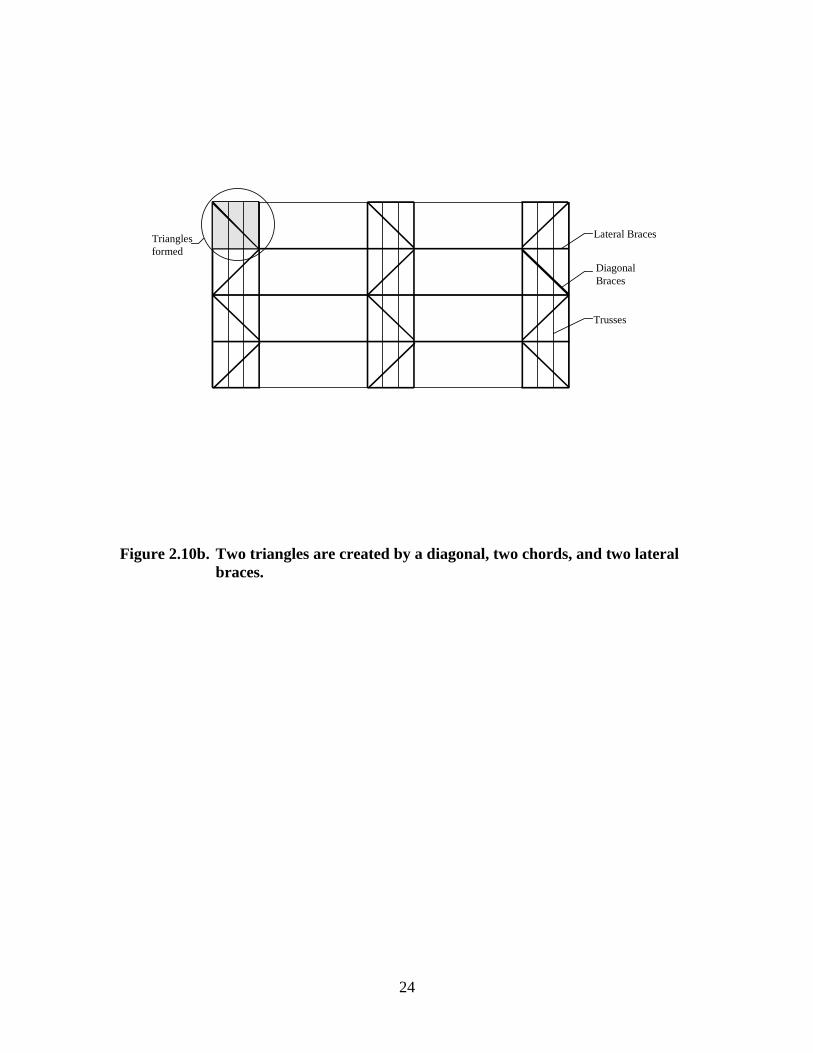
The temporary bracing strategy presented by DSB-89 involves the principles of triangles
in the various planes. Therefore, when designing temporary bracing for any structure,
diagonals must be used to help stabilize the lateral bracing along with distributing the
accumulated loads as shown in Figures 2.10 a and b.
DSB-89 provides design tables for quick reference when designing temporary bracing.
These tables are limited to the shapes previously mentioned and the lateral brace
configuration illustrated by each table. The design is based on the loads previously
mentioned without live loads included. Therefore, permanent bracing design for webs or
chords (without sheathing) can not be determined from the DSB-89 tables.
2.4.2 HIB-91 Pocketbook
Commentary and recommendations presented in this pocket size booklet are based on the
information provided by DSB-89. The main differences between DSB-89 and HIB-91
are the target audience and the truss spacing limits.

23
Lateral Braces
DiagonalBraces
Trusses
Figure 2.10a. Trusses with lateral and diagonal bracing installed as shown in DSB-89.
24
Figure 2.10b. Two triangles are created by a diagonal, two chords, and two lateralbraces.
Lateral Braces
DiagonalBraces
Trusses
Trianglesformed

25
HIB-91 pocketbook was developed for truss installers, contractors, and building
designers. The commentary and recommendations only apply to trusses spaced no
greater than 2-feet on-center with a span 60-feet or less, and 54-feet or less for mono
slope trusses. For spans over the stated limits, it is recommended that a registered
professional engineer design the temporary bracing.
2.4.3 HIB-91 Summary Sheet
HIB-91 Summary Sheet is developed for building designers and installers. The HIB-91
Summary Sheet contains primarily graphic information from HIB-91 Pocketbook. The
purpose of Summary Sheet matches the scope of the Pocketbook --up to 60 feet in span
(54 feet for monoslope trusses) and two feet or less on-center spacing. This document is
typically shipped with truss deliveries. Truss handling and bracing recommendations are
given by tables and drawings of braced roofs ready for the application of sheathing.
2.4.4 HIB-98 Post-Frame Summary Sheet
HIB-98 Summary Sheet is written for post-frame construction. A step-by-step procedure
is presented for truss installation. The recommendations provided by HIB-98 are only
relevant if the structure is a post-frame building with metal-plate-connected wood trusses.
The recommendations are based on several assumptions about the structure. One
important assumption stated is that the “end-walls have columns which extend to the top
chord of the gable end truss with adequate contact between the top chord and column for
a structural connection” (TPI, 1998). A second important assumption stated is that the
“side-wall columns extend above the mid-height of the truss heel at the connection of the
column and the truss” (TPI, 1998).
Temporary bracing schedules provided in HIB-98 were developed assuming a load
including two workers and their equipment. The document was produced for the post-
frame industry because no other documentation specific to widely spaced trusses was
available. A committee from the National Frame Builders Association (NFBA) was
appointed to develop the document and truss industry people were then called on for
review (Smith, 1999). HIB-98 was produced as a matter of safety and as a source of
useful information for the contractor and anyone else involved at the job site, and the

26
recommendations do not provide for resisting wind loads (TPI, 1998). Illustrations are
used to clarify the written information. Updated practices are illustrated including
column chaining but the specification is restricted to symmetrical triangular trusses with
top chord pitches of 3:12 or greater, and a flat bottom chord. For any other truss
configuration, it is recommended that a registered professional engineer be consulted.
2.4.5 Alpine/WTCA Video on Temporary Bracing
Alpine Engineered Products, Inc.(1996) in cooperation with WTCA produced a
temporary bracing video that contains a segment on "buckling behavior" of a
compression chord. A 60-foot parallel chord roof truss was placed in a testing laboratory,
and inadequately braced by a series of temporary lateral braces only. The bottom chord
was loaded with buckets containing weights that simulated the weight of truss installers.
With one bucket lowered onto the bottom chord, no noticeable truss movement is visible
in the video. Then, the second bucket was lowered onto the truss. The top chord slowly
buckled into the classic S-shape, with the chord severely bending between points of
lateral support. Finally, a third bucket was lowered on the truss and the truss violently
collapsed. Reviewing this sequence can be very educational for erection personnel and
others that design truss erection bracing, as "buckling behavior" may not be intuitive to
everyone involved in wood truss erection.
2.5 Other Documents Providing Guidelines for Temporary and
Permanent Bracing
Metal plate connected wood trusses are not the only building components that need to be
braced laterally to achieve maximum strength. Steel trusses must also be braced laterally
and therefore designers experience some of the same design challenges as for wood. The
AISC Load and Resistance Factor Design (LRFD) Specification is one design method
that considers lateral bracing and is discussed in Section 2.5.1. South Africa also has a
standard for considering lateral bracing of multiple members. The South African
Standard is discussed in Section 2.5.2.

27
nyb Pn.P ∗∗= 0080
L
PnS ny
b
∗∗=
8
2.5.1 LRFD Steel Approach
Dr. J.C. Smith, North Carolina State University, has written a textbook that follows the
steel LRFD approach for bracing requirements (Smith, 1996). In considering bracing
stiffness and strength requirements, the S-shaped buckling mode is desired. The S-
shaped bucking mode as previously discussed is the most desirable buckling mode
because brace forces act in opposing directions causing the net force of the system to
approach zero. To achieve the asymmetrical bucking mode the proper amount of
stiffness is required. The equations provided to determine the required strength are
dependent on the S-shaped buckling mode (Smith, 1996).
In Smith’s (1996) designs, all the braces are assumed to have the same stiffness. In the
case of three braces where h = L/4, where L is the length of the column and h is the
effective length, the displacement is maximum at the center brace and the other two
braces displace a reduced amount of 0.707 times the maximum (Smith, 1996). For h =
L/n where n is large, the strength requirements can be determined assuming the required
stiffness is provided for the column to buckle asymmetrically (Smith, 1996). Equations
2.3 and 2.4 are used to estimate the required strength and stiffness of the brace (Smith
1996).
(2.3)
(2.4)
where : Pb = the required bracing strength
Sb = required bracing stiffness
Pny = axial force in the column
n = number of braces
L = length of column
Equations 2.3 and 2.4 are derived based on statics of the deformed structure.

28
( )1
100
+∗
=N
P.P A
L
7.0LPLN nPC ∗=
The LRFD manual for steel is not directly applicable to wood. LRFD defines φPn, the
design compressive strength, with the assumption that the initial crookedness is a C-
shape with a limit of L/1000 (Smith, 1996). The maximum out-of-plumbness is L/500.
For wood these limits are not practical.
2.5.2 South African Standard Code of Practice…
South Africa has a provision in the South African Standard Code of Practice the
Structural Use of Timber, Part 2: Allowable Stress Design (South African Bureau of
Standards, 1994) for designing bracing for compression members. According to the
code, the force on each lateral restraint, for a single strut braced against buckling can be
determined using Equation 2.5.
(2.5)
where: PL = force on each lateral restraint
PA = average axial force in the strut due to dead load only
N = number of lateral restraints over full compression
The code states that for truss members, the number of lateral restraints, N, is the number
of restraints acting on the full span of the truss (South African Bureau of Standards,
1994).
For the case where lateral braces are used for multiple struts or trusses, Equation 2.6 can
be used to estimate the cumulative force on each lateral brace, CPLN:
(2.6)
where : PL = force on each lateral restraint
n = number of struts being restrained
n0.7 is based on the initial curvature of the struts. If all the struts had the same initial
curvature, then the cumulative effect would be directly proportional to the number of
struts. If the initial curvature of the members were random, then the cumulative effect on
the laterally induced forces would be directly proportional to the square root of n. Since

29
a combination of these two scenarios is possible, n0.7 is an approximation based on the
number of struts being restrained (South African Bureau of Standards, 1994).
2.5.3 Commentary for Permanent Bracing of Metal Plate Connected Wood
Trusses
The Wood Truss Council of America has produced a document to provide guidelines for
building designers who are responsible for permanent bracing design of metal plate
connected wood trusses. Commentary for Permanent Bracing of Metal Plate Connected
Wood Trusses (WTCA, 1999) contains an outline of the overall truss design
responsibilities as previously discussed in Section 1. The commentary did not provide
specific design requirements but it did outline the various locations in truss installations
that typically require a permanent bracing design.
For the case where a truss has a long span or a high pitch and a piggyback truss must be
used for shipping purposes, the building designer must design a bracing plan for the
supporting trusses. The building designer must indicate the required spacing between
diagonal braces needed to stabilize lateral braces. However, the truss designer must
specify:
• The required spacing between each lateral
• The thickness of the bracing
• And minimum connection requirements between the braces and both
pieces of the truss (WTCA, 1999).
The commentary provided several alternatives of how bracing the flat compression chord
of the supporting truss (Figure 2.7) could be designed and states the following options:
“... securely anchoring the lateral bracing to solid end walls designed
to resist the lateral loading, connecting the lateral bracing into the
roof diaphragm, adding diagonal bracing at intervals along the
length of the building, adding structurally rated sheathing, or some
other equivalent means” (WTCA, 1999).

30
There are no design guidelines however to help the building designer determine the
necessary capacity of the diagonals or other support options used.
The commentary addressed many truss configurations and provided bracing options for
different situations. It was clearly stated that the building designer has responsibility for
the design of permanent bracing and although some permanent lateral bracing
information may be shown on truss drawings, additional bracing design and details are
needed to erect a reliable roof. An example was provided to illustrate the bracing needs
the building designer needs to be concerned about (WTCA, 1999).
2.6 Previous Studies
2.6.1 Background
Miles Waltz studied the design requirements for bracing compression web members with
one lateral brace. The lateral support provided to the webs by the bracing was intended
to reduce the effective length of web members to prevent column buckling, or to increase
safe load capacity of a truss web.
Waltz (1998) discussed two different types of lateral bracing and the needs for each. The
first type of lateral bracing includes bracing to help trusses remain vertical under
conditions such as wind, earthquake, or construction events. This type of lateral bracing
helps provide stability to the entire structure and keeps trusses in their intended vertical
plane. Diaphragm sheathing or a lateral and diagonals bracing system can be used for
this type of support (Waltz, 1998). The second type of lateral bracing Waltz (1998)
discussed is designed to reduce the effective length for flexural buckling of individual
compression members. Under compression loads, the center of a compression member
tends to translate laterally. This second type of lateral bracing was the concentration of
Waltz’s (1998) study.

31
In his discussion of lateral bracing, Waltz (1998) also noted the lack of information
available for designing permanent truss bracing. Information is available for temporary
bracing, as previously discussed, to help prevent accidents stemming from gravity and
lateral loads during construction. Documents such as ANSI/TPI 1-1995 National Design
Standard for Metal Plate Connected Wood Truss Construction (TPI, 1995) discussed the
importance of such bracing and outlined design responsibilities for permanent bracing,
but specific design information is not provided (Waltz, 1998).
Waltz (1998) concentrated on the case of a single brace at the center of the web and the
effect of the brace on reducing the effective buckling length of the compression web. In
doing this, his research objective was to determine if one of four existing analysis models
could estimate required brace strength and stiffness. The four existing analysis models
considered include Plaut’s method (Plaut, 1993b; Plaut, 1993c), Winter’s Method (Winter,
1960), the 2% Rule (Throop, 1947), and Tsien’s method (Tsien, 1942).
2.6.1.1 Plaut’s Method
Plaut’s method for determining the required brace strength and stiffness for a single
discrete brace located at mid-height of a column includes the following assumptions:
• linear elastic columns
• linear elastic braces
• brace placement at the shear center of the column
• homogeneous, isotropic column properties
Plaut (1993) and Plaut and Yang (1993) used differential equations of equilibrium to
analyze stability of columns where the initial shape was assumed to be quadratic and
sinusoidal. Due to the complexity of the resulting equations, Plaut (1993) introduced
refined equations that could be used in design. Plaut’s (1993) equations are based on the
column buckling with reverse curvature. The additional moment caused by the reverse
curvature is thought to increase the brace force. Plaut (1993) accounts for the additional
moment with a 1.5 multiplier on the initial deflection of the column at mid-height.

32
( )
∆∆
+=
∆∆
+= 00 114
ide
req KL
PK
2.6.1.2 Winter’s method
George Winter (1960) used a rigid link model to estimate the strength and stiffness
requirements for a lateral brace. Up to this time, most researchers had concentrated
primarily on bracing strength alone. Winter (1960) recognized the need to include brace
stiffness in the analysis of a bracing system.
Based on research done at Cornell University, Winter (1960) reported that a minimal
amount of lateral bracing greatly increases the load capacity of columns and beams.
Using his rigid link model illustrated in Figure 2.11, Winter (1960) developed equations
to approximate the strength and stiffness requirements to fully brace an imperfect
column. The column was assumed to buckle asymmetrically and the initial shape was
assumed to promote the buckling mode. By summing moments about the support,
Winter’s (1960) Equations 2.7 and 2.8 can be derived.
(2.7)
where: Kreq is the stiffness required to produce full bracing,
Kid is the stiffness of an ideal column,
Pe is the Euler buckling load, and
∆ is the initial deflection or imperfection.
Fbr-req = Kreq ∆ = Kid (∆ + ∆0) (2.8)
However, Winter’s (1960) stated that in order to account for the eccentricities and
other imperfections in the column, initial lateral deflection at mid-height in Equations 2.7
and 2.8 can be approximately doubled when steel is the structural material. And when

33
K∆o ∆
P
P
∆o ∆
P
L/2
P
Fbr/2
Fbr/2
(a) (b) (c)
Figure 2.11. Winter’s Rigid Link Model for Imperfect, Braced Columns as depictedby Waltz (1998), Yura (1996), and Winter (1960).
(a)A column with an initial deflection, ∆0, with no axial load applied
(b)A column with an applied axial load and an additional deflection,∆, at mid-height
(c)Force diagram of the column under applied axial load as depictedby Yura (1996), and Waltz (1998)
L/2
L/2
K∆o

34
no other requirements are stated, a conservative estimate can be obtained by setting the
initial lateral deflection equal to the additional lateral deflection (∆e = ∆) experienced at
mid-height upon application of axial load. Pe can be assumed to follow code
requirements and multiplied by the factor of safety specified within the code
requirements (Winter, 1960).
Winter’s (1960) findings have proved to be very useful in understanding bracing behavior
(Yura, 1996). Yura (1996) expanded Winter’s (1960) work to provide insight into cases
where there is less than full bracing and the braces are not equally spaced. Yura (1996)
and Winter (1960) concluded that braces with a stiffness equal to the ideal stiffness are
not adequate for imperfect columns. The ideal stiffness is the bracing stiffness required
for a fully brace a column, with no imperfections, where the applied load is equal to the
Euler buckling load of the column. To fully brace a column, it is assumed that the lateral
support is immovable (Winter, 1960). The ideal stiffness is only adequate for perfect
columns.
2.6.1.3 Tsien’s method
Using the energy method, Tsien (1942) investigated the problem of determining the
strength and stiffness requirements for a laterally supported column. Tsien (1942)
assumed the imperfect column to be linear elastic and the brace was assumed to be
nonlinear elastic. A pair of equations relating the column load, the force in the brace and
the initial and final deflections was developed to solve for the brace force and the
deflection. One equation described the brace stiffness and the second equation described
the lateral deflection.
2.6.1.4 2% Rule
The 2% Rule is a strength model based on a percentage of the axial load in a column
needed to stabilize the column. Designers primarily use strength models during design
due to the simplicity of the calculations. In the derivation of the 2% Rule, the column
was assumed to be pinned at each end and at the center brace location. Throop (1947)
explained where the 2% Rule originated and Nair (1992) and Waltz (1998) illustrated the

35
use of a force balance in the development of the 2% Rule. The column is assumed to be
one-inch out of plumb for an assumed story height of 100 inches (Throop, 1947). A
compression chord braced at the center of its span will have a force of 1/100 above and
below the brace as depicted in Figure 2.12. A force balance for the free body diagram at
the brace is the basis for the 2% Rule (Nair, 1992).
2.6.2 Procedure
Waltz (1998) used finite element analysis to estimate the stiffness of support provided by
a lateral and diagonal bracing system for a number of braced truss webs in a row. The
finite element structural analog (FEM) Waltz used is illustrated in Figure 2.13. The
lengths of the web members studied were 4, 6, 8, and 10 feet. The angle theta (θ) was the
brace angle between the diagonal brace and lateral brace and should be approximately
45-degrees (TPI, 1991). Since the lateral and diagonal braces are assumed to intersect at
the front and back of the same web member, the angle will not be exactly 45-degrees for
the different length members (Waltz, 1998). (For the angle to be 45-degrees, the truss
spacing must be equally divisible by the square root of two times the web length.)
Waltz (1998) followed TPI (1991) temporary bracing recommendations for brace to web
connections. Therefore, two-16d Common nails were used for all wood-to-wood
connections. Springs were used to represent the load-deflection response of the nailed
connections. Equation 2.9 was developed by Mack (1966) to estimate the load-slip
response expected from a nailed connection using 2-16d Common nails.
( )( ) 7.07575.1 168.020.352 Ω−−+Ω= ekdF snail (2.9)
where: Fnail = load applied to a 2-16d nailed joint (pounds)
Ω = slip between the wood members of a 2-16d nailed joint (inches)
d = nail diameter (inches)
ks = species constant from Mack (1966)

36
α1
α2
Fbreq
P
P
where:
P = column load (pounds)
Fbr = brace force (pounds)
α1 = angle between brace and vertical plane
α2 = angle between brace and vertical plane
Force Balance
Assuming pins at brace ends and at the pointof brace attachment:
Fbr = P sin(α 1) + P sin( α 2)
When α1 and α2 are small and equal, sin αapproximately equals tan α. From Throop(1947), tanα was assumed to be 1/100,therefore:
Fbr ≈ (1/100 + 1/100) P
Fbr ≈ 0.02P, or 2% or P
Figure 2.12. A free body diagram and a force balance depicting the origin of the2% Rule as presented by Waltz (1998), Throop (1947) and Nair(1992).

37
X
Y
Lateral brace
Diagonal brace
N2
N1
N2
N1
N2
N1 N1 N1
N1
Fbr Fbr Fbr Fbr
where:
Fbr = brace force
N1 = one-dimensional nailed joint
N2 = two-dimensional nailed joint
θ = brace angle (radians)
θ
Figure 2.13. Finite Element Structural Analog for a Diagonal/Lateral BraceAssembly from Waltz (1998)

38
Waltz (1998) used this relationship for modeling nail slip for all analyses. Waltz’s FEM
contained two types of nailed connections, N1 and N2 connections, as illustrated in Figure
2.13. N1 connections represented a uniaxial load-slip behavior such as the case of a
diagonal brace and a web. The connection between the diagonal brace and the web only
resists vertical loads in the analog of Figure 2.13.
N2 connections only occur at the middle and ends of the brace and consist of both X and
Y components. The N2 connections occur at the middle and ends because there is one
connection between the diagonal and the web, and a second connection between the web
and the continuous lateral brace (CLB). Two springs were used to model the
connections. "The stiffness of the component spring within these connections was
calibrated so that the resultant force experiences the load-slip behavior" of Equation 2.9
in the resultant direction (Waltz, 1998). Figure 2.14 illustrates the relationship of
Equation 2.9. For this equation to be valid, a maximum allowable slip between wood
members using two-16d Common nails is 0.1 inches, and the 0.1 inch slip value was
defined as failure in the Waltz study as recommended by Mack (1966).
Waltz (1998) assumed the following for creating the structural analog depicted in Figure
2.13:
• All trusses connected by the lateral brace were the same size and configuration;
all uniformly loaded (same compressive force in each web)
• Each diagonal brace was oriented at approximately 45-degrees from the webs
long axis
• Truss spacing was 610 mm (24 inches) on center
• All lateral and diagonal braces were 2 x 4 Douglas-fir Larch lumber with modulus
of elasticity of 8,270 MPa (1,200,000 psi)
• Two 16d Common nails with a diameter of 4.1mm (0.161 inches) were in all
wood-to-wood connections
• One diagonal brace for each piece of lateral brace lumber (no lateral brace
splices)

39
Figure 2.14. Load-slip response for a 2-16d Common nail connection between two-2x4 Spruce-Pine-Fir wood members.
0
100
200
300
400
500
600
0 0.02 0.04 0.06 0.08 0.1
Slip between wood members across the joint (inches)
Fn
ail,
Lo
ad a
cro
ss t
he
join
t (p
ou
nd
s)

40
• The ends of each diagonal brace were nailed to a wood member support (pin
reaction that included nail slip)
• All compression webs transfer a lateral load of equal magnitude and direction to
the lateral brace
The finite element structural analogs were developed to estimate the stiffness of the brace
support provided to the varying length members (Waltz, 1998).
Brace curves were developed from the data obtained from the finite element models. The
process involved analyzing the bracing system consisting of one lateral brace attached to
n-webs and one diagonal brace that resisted the movement of the lateral brace. The force
in each brace was increased (simulating more load in the webs) and the lateral deflection
response was determined for the web(s) at the point of lateral brace attachment. When
multiple webs were considered, the magnitude of the force due to the CLB was increased
to determine the largest horizontal deflection experienced by a web member (Waltz,
1998). In reality, the webs did not all deflect the same amount. Waltz’s (1998) FEM
allowed slip in the joints and compression/stretch of the lateral brace. He concluded the
compression/stretch in the lateral brace was negligible and therefore he assumed the
lateral movement of the n-webs as part of a braced system was approximately equal.
After determination of the brace load for one truss and the corresponding lateral
deflections, an additional truss was considered. The incremental process continued until
a total of 10 trusses had been considered. A non-linear plot illustrating the incremental
brace force versus the lateral deflection at the braced web(s) for varying numbers of
trusses was developed. These plots are the brace curves used in Waltz (1998) research.
2.6.3 Testing
To perform the braced web experiments, a supply of lumber was requested from three
sawmills. Two grades of lumber were tested, Select Structural and Standard. A total of
800 pieces were tested varying in lengths of 4, 6, 8, 10 feet. Four hundred (400) samples
were Select Structural and 400 samples were Standard grade. The moisture content for
the testing specimens was requested to be 19% or less.

41
The Waltz (1998) test apparatus, shown in Figure 2.15, consisted of two steel pipes on
the long sides and heavy steel beam sections on the short ends. A hydraulic cylinder was
used to produce the axial load on the columns. For each test column, the ends were
shimmed into a U-shaped boot to help prevent bending about its strong axis. Hinges
were placed at each column end at designated web length. A lateral brace was simulated
at the mid-height of the column using a mechanical brace controlled by a computer. The
computer allowed the brace stiffness to be variable because the stiffness can effect the
column performance and the brace load that develops.
Before testing the specimens, initial column measurements were taken. The
measurements included cross sectional dimensions, moisture content, modulus of
elasticity, weight, initial column deflection at mid-height and the initial shape of the
column.
The second step of the testing process was to determine the axial test load for each
column. Waltz (1998) assumed the 2x4 Douglas-fir Larch columns were braced
sufficiently and the effective length of the column was one-half of the total length. The
maximum axial test loads to be applied were intended to be as close to the critical column
strength as possible and did not include safety and load duration factors (Waltz, 1998).
The brace stiffness required for testing was then selected using the brace curves
previously discussed. For each sample, brace force curves were compared. If the brace
support curves did not intersect with the theoretical brace analysis curve then the
theoretical brace requirements were not met (Waltz, 1998). The most flexible brace
support curve that intersected the theoretical brace curve for Plaut’s method was chosen
for testing purposes.
2.6.4 Results
The initial measurements taken before testing on moisture content, member dimensions,
weak-axis moment of inertia, and dry weight per unit length by inspection showed little

42
Figure 2.15. Test apparatus from Waltz (1998). The apparatus was used to test800 lumber samples. The test apparatus was designed for Waltz’sresearch.

43
( ) ( )( )predictedbr
predictedbractualbr
theory F
FFD
−=
differences between test groups (Waltz, 1998). A majority of the members had an initial
profile of a “C-shaped” column. The modulus of elasticity, MOE, however, varied based
on length and grade. A flatwise bending test was used to measure the longitudinal MOE.
Within each grade, the MOE was less for the four-foot lengths than for the other three
lengths. The MOE was considered to add variability to the results and were therefore
considered in the test results.
Eight of the 774 columns tested failed when the column buckled asymmetrically. Fifteen
of the twenty-one failures occurred because the brace force exceeded the capacity of the
brace defined by 0.1-inch (2.5 mm) slip in the connection. Brace instability occurred
when the stiffness selected for the test was inadequate to brace the column (Waltz, 1998).
2.6.5 Performance Variables
Waltz (1998) calculated the relative deviation, Dtheory, between the predicted forces by the
FEM and various brace models discussed in Section 2.6.1 and the experimental brace
force for each test column. The relative deviation was defined in Equation 2.10:
(2.10)
The relative deviation was considered a “performance variable” to compare the
prediction performance of the different theories (Waltz, 1998).
His performance variable, Dtheory ranged from negative one to positive infinity. If Dtheory
was less than zero, the brace analysis theory was considered to be a conservative
overestimate of the support requirements. Dtheory greater than zero signified the estimate
was not conservative. Dtheory was calculated for each of the test columns and each of the
four prediction methods (Waltz, 1998).
For Waltz’s research, Dtheory, was based on the predicted and measured brace force at
maximum deflection. The predicted brace force for each method was plotted along with
the brace support curve for the test column. Looking at the actual deflection that

44
occurred during testing enabled Waltz to determine Dtheory for each test column. Both
strength and stiffness are considered due to the brace support curves, except for the 2%
Rule. When the predicted brace force exceeded the actual brace force, the theory was
characterized as overestimating both the strength and stiffness requirements of the
column. When the predicted brace force was less than the actual brace force, the theory
was considered to underestimate the requirements (Waltz, 1998).
Non-parametric methods were used to compare the performance variables, which
included DPlaut, DWinter, DTsien, and D2% Rule, among the species and lengths. Waltz (1998)
determined there was not a significant grade effect on the mean predictions of Tsien’s
equation and the 2% rule but Plaut’s and Winter’s method may be slightly influenced by
grade especially for the shorter columns.
Pooling the data from both grades, Waltz (1998) tested for brace length effects. No
significant length effect was found for the mean performance of the 2% Rule, but length
had a significant effect on the mean Dtheory for the other three methods. The lumber
could effectively be divided into two groups based on the lengths of the members: 4/6
feet and 8/10 feet.
The initial column profile was investigated in terms of its effect on the performance
variable, Dtheory. The comparisons indicated all four of the bracing theories to be less
conservative for “C-shaped” columns than for “S-shaped” columns. It was therefore
concluded that the initial “C-shaped” profile represents the worst case scenario for lateral
bracing design (Waltz, 1998).
Waltz (1998) performed paired statistical tests within each of the two pooled length
groups. It was determined that there was a significant difference between the three
analysis methods.

45
Plaut’s method proved to be the most conservative, for most cases. Plaut’s method was
consistently conservative and more accurate than the 2% Rule based on the analysis of
the performance variable, Dtheory.
The 2% Rule was the most conservative but it also provided the most variable estimate of
the required brace force. The 2% Rule does not take into account the stiffness
requirements and may not be the best for brace design (Waltz, 1998).
2.6.6 Conclusion
Waltz (1998) concluded that either Plaut’s or Winter’s method could be used. Plaut’s
method is more conservative and has the lowest prediction variability. Winter’s method
provided the best prediction of the actual brace needs although it was more variable.
With proper adjustments, either method could be used to estimate the required bracing
needs.

46
3. Finite Element Modeling and Analysis
3.1 General Assumptions
To accomplish the research objectives of this project, several issues must be considered.
First, as previously discussed, webs can buckle in different modes (Plaut and Yang, Y.G.,
1993; Plaut and Yang, Y.W., 1995; Waltz, 1998; Winter, 1960; Zuk, 1956). The critical
case for permanent bracing, in terms of laterals and diagonals, occurs when the C-
buckling mode is assumed (Waltz, 1998). Therefore, the C-buckling mode was the only
buckling mode investigated in this research study. Diagonals must be designed to resist
the maximum lateral load developed by the n-CLB’s. Net lateral restraining force per
roof truss due to n-CLB’s (NLtruss), must be determined for different levels of
compression force in the chord, varying numbers of CLB’s, different chord sizes and
different grades of lumber while the column is deflected in a C-shape buckling mode.
3.2 Design Considerations
3.2.1 n-CLB’s
There are many truss applications where multiple CLB’s are necessary to support chords
that are not automatically braced with sheathing. For example, multiple CLB’s are used
to brace an unsheathed chord of a piggyback truss system. A piggyback truss system
consists of two (or more) trusses connected together after shipping. The bottom truss is
typically a trapezoid shape and is often referred to as the supporting truss. The top truss,
supported by the supporting truss, is typically a triangular shape and is often referred to
as a cap truss. The top chord of the supporting truss of a piggyback truss system can vary
in length and must be braced to reduce the weak axis slenderness ratio. Figure 3.1
depicts a piggyback truss system with n-CLB’s, and two diagonal braces bracing j-
trusses. The trusses are assumed to buckle in a C-shape mode as depicted in Figure 3.1.
The net restraining force to be carried by the diagonal braces is an unknown and must be
determined to design the connection between the diagonal braces and the trusses.

47
Figure 3.1. Example truss system with j-flat top trusses being braced by twodiagonals, n-CLBs, and an axial compressive force in the top chordsof the trusses.
Compression force in eachtruss
Trusses ContinuousLateral Braces
Diagonal BracesRoof Sheathing

48
3.2.2 One CLB
A column, braced in the center of its span, as illustrated in Figure 3.2, can be braced
using the 2% Rule (TPI, 1989). When the single brace is applied, the column can buckle
as shown in Figure 3.3. Currently, the 2% Rule is the most Common and accepted design
practice used for designing permanent bracing for a compression web that utilizes one
continuous lateral brace with diagonals spaced at some interval. When the 2% Rule is
used, as discussed previously, the bracing force required to stabilize one CLB is assumed
to be 2% of the axial force in the chord. While the 2% Rule produces reasonable results
for the case of one CLB, the 2% Rule does not produce reasonable results for a
compression chord, where multiple CLB’s are used. Frequently, more than one CLB is
needed on a chord for added strength. To prevent the displacements of points A and B in
Figure 3.3, CLB’s could be added to produce the two buckling modes depicted in Figures
3.4a and b.
3.2.3. Two CLB’s
The buckling modes depicted in Figures 3.4a and b are based on the use of two CLB’s to
laterally support the column. The 2% Rule does not apply because it was based on a
single brace located at the mid-span point of the column as described in Section 2.6.1.4.
Figure 3.4a depicts a column with two lateral braces with a multiple S-shape buckling
mode. The net lateral restraining force is based on the direction of the force in the
CLB’s, depicted by vectors in Figure 3.4a. If the force in one CLB is in one direction
and the force in the second CLB is in the opposite direction, then the net lateral
restraining force would be significantly lower than if they are both in the same direction.
Figure 3.4b depicts a column with two lateral braces with a C-shape buckling mode. The
net lateral restraining force in this case would be critical for brace design since the forces,
represented by vectors in Figure 3.4b, act in the same direction.

49
Figure 3.2. A column braced at center span requires 2% of the axial compressiveforce to stabilize the point of brace attachment from lateral movement(TPI, 1989).
C
C
2% * C

50
Figure 3.3. The column buckles in an S-shape as depicted when a single brace isapplied.
C
C
2% * C
B
A

51
(a) (b)
Figure 3.4. (a) The column buckles in a multiple S-shape mode as depicted whentwo lateral braces are applied.
(b) The column can buckle in a C-shape mode as depicted when twolateral braces are applied. The C-shape buckling mode is critical forbrace design because the lateral forces due to the braces act in thesame direction and are therefore additive.
C
C
C
C

52
( )2
2
kL
EIPcr
π=
An important issue resulting from the use of two CLB’s is determining the net lateral
restraining force for the two cases depicted in Figures 3.4a and b. Figure 3.4b represents
the most critical case for brace design that can occur and will be the case considered for
this research.
3.3 SAP2000 (CSI, 1995)
SAP2000 (CSI, 1995) is a structural analysis program that can be used for basic as well
as complicated design problems. To verify that SAP2000 (CSI, 1995) was usable in this
research, the buckling load of columns (with known theoretical solutions) of three
different lengths was determined using SAP2000 and the theoretical formulae. The
computer output was compared to the theoretical solution and then the results were
studied to determine if the computer model was working as intended.
To accurately represent a column in a finite element analysis, it was necessary to divide
the column into multiple elements. A convergence test was performed to determine the
number of elements required to accurately represent the column under the applied
compression loads.
To begin, a 12 foot column was represented by one element in SAP2000 (CSI, 1995)
with one end support fixed and the other end free to translate and rotate. A compressive
load was applied to the column and using the p-delta analysis tool of SAP2000 (CSI,
1995), the column was tested to determine if capacity of the column could withstand the
load. The load was progressively increased until the column failed. A failure in
SAP2000 (CSI, 1995) is indicated by a error message during the analysis of the structure.
At the point of failure, the applied compressive load was recorded as the buckling load of
the column. The results from the computer analysis were then compared to the results of
the hand calculations determined from Euler’s buckling equation, Equation 3.1.
(3.1)
where: Pcr = critical buckling load (pounds)

53
E = modulus of elasticity (psi)
I = moment of inertia about the weak axis (in4)
k = stiffness coefficient based on support conditions
L = effective length of the column (inches)
The buckling load determined from the computer analysis was then divided by the
theoretical value determined by Euler’s equation and the number was recorded in Table
3.1. The preceding steps were then repeated for the same column represented by an
increasing number of elements.
The above procedure was repeated for fixed-pinned supports and pin-pin supports. Once
convergence was determined for a twelve-foot column the process was repeated for a
four-foot column and a thirty-foot column. Results of the calculations were summarized
in Tables 3.1, 3.2, and 3.3. It was concluded from the convergence data that the three
assumed column conditions represented using three elements was sufficiently accurate.
3.4 Waltz’s Structural Analog in SAP2000 (CSI, 1995)
The first step to produce a data file for SAP2000 (CSI, 1995) to analyze Waltz’s
structural analog was understanding the connections. Two different connections were
necessary to model the behavior of the nailed connections. One type of connection
consisted of two springs and represented the nailed connections between the diagonal
brace and the truss panel point and at the middle of the diagonal brace and web. The
second type of connection consisted of one spring that was used to represent the
connection between the diagonal brace and the web members. The single spring
connection is based on the assumption that there is negligible weak-axis lateral support
for the diagonal by the buckling web member (Waltz, 1998). The single spring acted in
the vertical direction only.
To enter the analog into SAP2000 (CSI, 1995), a grid was developed on a one-inch scale.
Nodes were placed at the geometry described by Waltz (1998). Members were assigned
properties to represent Douglas Fir-Larch and a modulus of elasticity equal to 1,200,000

54
Table 3.1. Comparison of Euler buckling loads to buckling loads determineusing SAP2000 (CSI, 1995) for a twelve foot column.
# of
elements
fixed-
free
fixed-
pinned
pin-
pin
Actual / theoretical fixed-free fixed-pinned pin-pin
Theoretical 140 1147 562
1 element 141 1708 683 1.007 1.48 1.215
2 elements 140 1179 566 1.00 1.027 1.007
3 elements 140 1156 562 1.00 1.007 1.00
4 elements 140 1151 562 1.00 1.003 1.00

55
Table 3.2. Comparison of Euler buckling loads to buckling loads determineusing SAP2000 (CSI, 1995) for a four foot column.
# of
elements
fixed-
free
fixed-
pinned
pin-
pin
actual / theoretical fixed-free fixed-pinned pin-pin
Theoretical 1265 10327 5060
1 element 1273 >15000 6152 1.006 >1.45 1.212
2 elements 1264 10569 5086 0.999 1.023 1.005
3 elements 1264 10362 5055 0.999 1.003 0.999
4 elements 1264 10316 5049 0.999 0.999 0.998

56
Table 3.3. Comparison of Euler buckling loads to buckling loads determineusing SAP2000 (CSI, 1995) for a thirty foot column.
# of
elements
fixed-
free
fixed-
pinned
pin-
pin
actual / theoretical fixed-free fixed-pinned pin-pin
Theoretical 22.5 184 90
1 element 22.6 273 109 1.004 1.48 1.211
2 elements 22.5 189 90 1.00 1.027 1.00
3 elements 22.4 185 90 0.996 1.005 1.00

57
psi was assigned to each member. The lumber was oriented to assure that the 1.5-inch
dimension was the depth and the 3.5-inch dimension was the width.
Two-dimensional connections at the ends of the diagonal and the one-dimensional
connections between the diagonal and the compression webs were represented by support
springs. The support springs were assigned a stiffness based on Equation 2.9 from Mack
(1966).
Waltz (1998) had 23 failures during his research. Waltz concluded in his study that
Mack’s (1966) curve could be represented linearly due to the instability failures that
occurred in the nonlinear portion of their brace support curves.
To represent Mack’s curve linearly, the secant modulus was determined for the different
forces. To find the secant modulus, a slip was determined and then the corresponding
force was solved for using Equation 2.9. The force g(x), where x is slip, was determined
by a line drawn from the origin to the point (x,g(x)). The slope of the line was the
stiffness for the specified force and slip. When the force is increased, the stiffness
decreases based on the changing secant modulus.
Connections between the diagonal brace and the compression chord at the middle of the
brace and between the diagonal brace and the CLB were represented by internal springs
(in SAP2000 (CSI, 1995), terminology). The stiffness of the internal springs was
determined using the secant modulus as previously explained. Internal springs in
SAP2000 (CSI, 1995) are represented by “nllink” elements. Two types of nllink
elements can be specified, zero-length elements and elements that connect two joints. A
zero-length element can consist of either a single joint with a spring connection to a
reaction support, or two-joint elements sharing the same location in space. The
coordinate system varies depending on the type of nllink element specified in the analog.
To develop Waltz’s (1998) analog, only one type of nllink element was used. A joint-to-
joint nllink element was used to represent the horizontal spring connection between the

58
diagonal brace and the truss web. A second joint-to-joint nllink element was used to
provide a load path for the force to get from the CLB through the diagonal brace and into
the web. Each nllink element had six degrees of freedom and a spring stiffness
(translational or rotational) can be specified for any of the six degrees of freedom. The
degrees of freedom that receive no stiffness must be given restraints or other supports for
stability purposes (CSI, 1996).
Waltz (1998) concluded that the axial deformation within a CLB member could be
neglected. Therefore, for Waltz’s (1998) analog, restraints were used to support the
nllink elements. In SAP2000 (CSI, 1995), there is positive moment continuity across
nodes but there is no moment continuity across springs. For this reason, restraints must
be applied to help ensure stability about the model and the springs. The nodes on both
sides of the nllink elements were restrained in the Y-direction, Z-direction, and all three
rotations. In other words, the nllink elements or springs were only allowed to deflect in
the X-direction or axially. Figure 3.5 depicts Waltz’s (1998) structural analog
conceptually as entered in SAP2000 (CSI, 1995).
To analyze a model in SAP2000 (CSI, 1995), the available degrees of freedom must be
specified. To analyze Waltz’s (1998) structural analog, the available degrees of freedom
include: UX, UZ, RY. In other words, the structure can move in the X- and Z-directions
and can rotate about the Y-axis.
3.5 System Analogs
3.5.1 Five Chords Braced by Three CLB’s
The first system structural analog analyzed using SAP2000 (CSI, 1995) represented five
eight-foot roof trusses spaced twenty-four inches on center, three continuous lateral
braces (CLB’s) spaced twenty-four inches on center and one diagonal, as depicted in
Figure 3.5. The lumber used in the construction of the structural analog was assumed to
be 2x4 STUD Spruce-Pine-Fir, with a modulus of elasticity of 1,200,000 psi for the
CLB’s and 2x4 No. 2 Southern Pine, with a modulus of elasticity of 1,600,000 psi for the

59
A
B
D
E
P P P P P
C
Z
X
Figure 3.5. The structural analog represents 5 trusses with an initial curvature,three continuous lateral braces (CLB’s), and 1 diagonal member. Theinitial curvature is in one direction and is exaggerated for visualpurposes.

60
=∆
L
xpiLi
*sin
200
truss chords. The truss chords were assumed to be a column with pin connections on
one-end and roller connections on the other.
To model the inward movement of both chord ends, roller supports would need to be
used on both ends of the truss chords to allow deflection on both sides. However,
instability would occur during analysis of the structure if such support conditions were
applied to the structural analog. The structural analog has quarter symmetry meaning the
upper left quarter of the structure is symmetric with the lower right quarter of the
structure and the same for the upper right quarter and the lower left quarters of the
structure. The structure is said to be symmetric about the center point of the structural
analog. However, if a roller support is applied to the truss at the center point of the
structural analog, the applied loads cause the trusses to translate improperly and bending
action occurs in the CLB’s. Based on the problems associated with the above support
conditions, the data file for SAP2000 (CSI, 1995) was created using the pin and roller
support conditions originally described. All connections between chords and braces were
assumed to be made with 2-16d Common nails and were represented with springs to
model the slip in the connection.
ANSI/TPI 1-1995 (TPI, 1995) installation limits were assumed for all chord lengths
studied. Equation 3.2 described the chord member as having a half sine wave
configuration, with an assumed initial curvature of L/200.
(3.2)
where: ∆i = assumed initial deflection of the truss chord,
L = length of the compression chord, and
x = the distance from the member end, inches
pi is in radians.
A deflected chord member, by nature, is a smooth curve as opposed to a series of straight
lines. Therefore, the half sine configuration was assumed and used in all analyses.

61
Connections A, B, C, D, and E, shown in Figure 3.5, were each modeled by a horizontal
spring and a vertical spring. (Two springs were required for each nail connection.) The
horizontal spring represented the lateral load-slip relationship slip at the diagonal and
chord member connection. The vertical spring represented the connection slip in the
vertical direction between the diagonal member and the chord member. The resultant
spring force was determined for each of the connections between the diagonal brace and
the truss chord members after the analysis was completed using vector addition.
A spring acting in the horizontal direction and a spring acting in the vertical direction
represented the connections between the chords and the CLB. Joint C, as depicted in
Figure 3.6, consisted of the two-spring connection between the diagonal member and the
chord member and the two-spring connection between the CLB and the chord member.
One horizontal spring or nailed connection allows the load to be transferred into the CLB
and the other nailed connection transferred the load out of the CLB. Joints A and E,
(Figure 3.5), represented the connection between the diagonal and the chord at the point
where the chord is connected to the truss panel point and roof or ceiling diaphragm.
Once the data file for the structure was completed, loads were applied and the structure
analyzed. Design load was determined based on the National Design Specification for
Wood Construction (AF&PA, 1997) and an axial load ranging from 684 to 3,421 pounds
was applied to each chord. The allowable design load (Fc’) was determined to be 6,842
pounds. However, 50% of the allowable compressive load based on an le/d ratio of 16 is
a typical load level in a wood truss chord. The load was increased from 10% to 50% of
Fc’. Load levels above 50% were not studied because the iterative solution was manually
conducted, and for higher load levels, manual solutions were not feasible due to the
number of iterations required. In retrospect, ANSYS 5.4 (ANSYS, 1997) would have
been a better choice of finite element analysis program to analyze the system at load
levels approaching 100% of Fc’. Design load was based on the grade, species
combination, and size of lumber and the duration of load, which in this case is assumed to
be 1.15 for snow plus dead loading.

62
Chord
CLB
Vertical spring betweendiagonal brace and trusschord
Horizontal springbetween diagonal braceand truss chord
(a)
(b)
Figure 3.6. (a) The connection between the chord member and the CLB isrepresented by a horizontal and a vertical spring.
(b) The connection between the CLB and the chord member is alsorepresented by a horizontal and a vertical spring.
Chord
Diagonal Brace
Horizontal springbetween diagonal braceand truss chord
Vertical spring betweendiagonal brace and trusschord

63
49.3*265 += SGks
The stiffness values for the 2-16d nailed connections were determined using Equation 2.9
from Mack (1966). As previously discussed in Section 3.4, the secant modulus method
was used based on the load and deflection. Since Mack’s (1966) paper did not provide a
species factor for Spruce-Pine-Fir, a linear regression was performed to determine the
equation suitable for that particular species. Equation 3.3 is the regression equation that
was used to determine the species factor for use in Mack’s (1966) load-slip equation.
(3.3)
where: ks is the species factor for use in Mack’s (1966) equation, and
SG is the specific gravity for the species, in this case Spruce-Pine-Fir.
Equation 3.4, derived from Mack’s (1966) equation, was used in the analysis for the
connection force in a Spruce-Pine-Fir connection modeled in SAP2000 (CSI, 1995).
( )( ) 7.075168.020.3618 Ω−−+Ω∗= eFnail (3.4)
where: Fnail = load applied to a 2-16d nailed joint (pounds), and
Ω = slip between the wood members of a 2-16d nailed joint (inches).
A linear spring stiffness was estimated for each joint and the structural analog of Figure
3.5 was analyzed. The calculated spring forces were then compared to the specific force
and displacement used to input the linear spring (secant modulus) constants. The new
stiffness value for each spring was entered into SAP2000 (CSI, 1995) and the structure
was analyzed again. The procedure was repeated until the force in the springs matched
the assumed force and displacement used to calculate the secant modulus spring stiffness
within a tolerance of 1%.
The deflected shape, as depicted in Figure 3.7, resulted from the final stiffness of each
spring, with 3,421 pounds of axial force applied to the chords. The moment diagram,
Figure 3.8, illustrated the moment that developed due to the bracing connections and the
initial curvature. The moment is zero at each end of the chords due to the moment-free

64
Figure 3.7. Five trusses with three continuous lateral braces and one diagonalbrace primarily deflected in the C-mode except at the point ofdiagonal brace connections.

65
Figure 3.8. Moment is developed in the chords primarily due to the bracingconnections and the initial curvature of the chord members.

66
pin supports. The moment is continuous across the nodes verifying the continuity of the
wood members.
3.5.2 Six Chords Braced by Nine CLB’s
The second system structural analog analyzed using SAP2000 (CSI, 1995) represented
six twenty-foot roof trusses spaced twenty-four inches on center, nine continuous lateral
braces (CLB’s) spaced twenty-four inches on center, and two diagonals in a V-shape with
an angle of 45-degees, as depicted in Figure 3.9. The lumber used in the construction of
the structural analog was assumed to be 2x4 STUD Spruce-Pine-Fir, with a modulus of
elasticity of 1,200,000 psi for the CLB’s and 2x4 No. 2 Southern Pine, with a modulus of
elasticity of 1,600,000 psi for the truss chords. The truss chords were assumed to be
columns with roller connections, free to translate in the vertical or Z-direction, on both
ends. Roller connections free to translate in the horizontal or X-direction were used on
the chords where the middle CLB crossed the chords to stabilize the structure, but still
allowed the chords to deflect. The roller connections could be applied to the chords at
the center CLB because of the symmetry of the structure about the middle CLB. All
connections between chords and braces were assumed to be made with 2-16d Common
nails and were represented with springs to model the slip in the connection. The
calculated spring constants were based on the assumption that both members of the joint
were Spruce-Pine-Fir since data were not available for joints made with different species.
ANSI/TPI 1-1995 (TPI, 1995) installation limits were assumed for all chord lengths
studied. Therefore, to model the chord member with initial curvature, the nodes
were assigned for the data file for SAP2000 (CSI, 1995) using Equation 3.2 to produce a
half sine wave configuration, with an assumed initial curvature of L/200.
All connections between the truss chords and the diagonals were modeled by a horizontal
spring and a vertical spring. The horizontal spring represented the lateral load-slip
relationship slip at the diagonal and chord member connection. The vertical spring
represented the connection slip in the vertical direction between the diagonal member and

67
Figure 3.9. The structural analog represents 6 trusses with an initial curvature, 9continuous lateral braces (CLB’s), and 2 diagonal bracing membersin a V-shape. The initial curvature is in one direction andexaggerated for visual purposes.
A
B
P P
C
G
L
P
K
P
P
J
P
D
P
I
P
P
E
H
P
P
F
P
CLB’sspaced24” oc
Z
X

68
the chord member. The resultant spring force was determined for each of these
connections, after the analysis was completed using vector addition.
A spring acting in the horizontal direction and a spring acting in the vertical direction
represented the connections between the chords and the CLB. Joint F and G, as depicted
in Figure 3.9, consisted of the two-spring connection between the diagonal member and
the chord member and the two-spring connection between the CLB and the chord
member. One horizontal spring or nailed connection allows the load to be transferred
into the CLB and the other nailed connection transferred the load out of the CLB. Joints
A and L, (Figure 3.9), represented the connection between the diagonal and the chord at
the point where the chord is connected to the truss panel point and roof or ceiling
diaphragm.
Once the data file for the structure was completed, loads were applied and the structure
analyzed. Design load was determined based on the National Design Specification for
Wood Construction (AF&PA, 1997) and an axial load ranging from 684 to 3,421 pounds
was applied to each chord. The allowable design load (Fc’) was determined to be 6,842
pounds based on an le/d ratio of 16. The load was increased from 10% to 50% of Fc’. As
for the previous case, load levels above 50% were not studied because the iterative
solution was manually conducted and for higher load levels manual solutions were not
feasible due to the number of iterations required. Design load was based on the grade,
species combination, size of lumber, and the duration of load, which in this case is
assumed to be 1.15 for snow plus dead loading.
The stiffness values for the 2-16d nailed connections were determined using Equation 3.4
from Mack (1966). As previously discussed in Section 3.4, the secant modulus method
was used based on the load and deflection.
A linear spring stiffness was estimated for each joint and the structural analog of Figure
3.9 was analyzed. The calculated spring forces were then compared to the specific force
and displacement used to input the linear spring (secant modulus) constants. The new

69
stiffness value for each spring was entered into SAP2000 (CSI, 1995) and the structure
was analyzed again. The procedure was repeated until the force in the springs matched
the assumed force and displacement used to calculate the secant modulus spring stiffness
within a tolerance of 1%.
The deflected shape, as depicted in Figure 3.10, resulted from the final stiffness of each
spring, with 3,421 pounds of axial force applied to the chords. The moment diagram,
Figure 3.11, illustrated the moment that developed due to the bracing connections and the
initial curvature. The moment is zero at each end of the chords due to the moment-free
pin supports. The moment is continuous across the nodes verifying the continuity of the
wood members.
3.5.3 Eleven Chords Braced by Nine CLB’s
The third system structural analog analyzed using SAP2000 (CSI, 1995) represented
eleven twenty-foot roof truss chords spaced twenty-four inches on center, nine
continuous lateral braces (CLB’s) spaced twenty-four inches on center and two diagonals
in a V-shape with an angle of 45-degrees, as depicted in Figure 3.12. The lumber used in
the construction of the structural analog was assumed to be 2x4 STUD Spruce-Pine-Fir,
with a modulus of elasticity of 1,200,000 psi for the CLB’s and 2x4 No. 2 Southern Pine,
with a modulus of elasticity of 1,600,000 psi for the truss chords. The truss chords were
assumed to be columns with roller connections, free to translate in the vertical or Z-
direction, on both ends. Roller connections free to translate in the horizontal or X-
direction were used on the chords where the middle CLB crossed the chords to stabilize
the structure, but still allowed the chords to deflect. The roller connections could be
applied to the chords at the center CLB because of symmetry of the structure about the
middle CLB. All connections between chords and braces were assumed to be made with
2-16d Common nails with both members of the joint being Spruce-Pine-Fir for the
purpose of validating the slip behavior of the joint.
ANSI/TPI 1-1995 (TPI, 1995) installation limits were assumed for all chord lengths
studied. Therefore, to properly model the chord member with initial curvature, the nodes

70
Figure 3.10. Six trusses with nine continuous lateral braces and two diagonalbraces primarily deflected in the C-mode except at the point ofdiagonal brace connections.

71
Figure 3.11. Moment is developed in the chords primarily due to the bracingconnections and the initial curvature of the chord members.

72
A
D
P P P P P P
C
EF
G
H
I
J
KL
P P P P P P
CLB’sspaced24” oc
P
P
P
P
P
P
P
P
Z
X
B
P
P
Figure 3.12. The structural analog represents 11 trusses with an initial curvature,9 continuous lateral braces (CLB’s), and 2 diagonal bracing membersin a V-shape. The initial curvature is in one direction andexaggerated for visual purposes.

73
were assigned for the data file for SAP2000 (CSI, 1995) using Equation 3.2 to produce a
half sine wave configuration, with an assumed initial curvature of L/200.
All connections between the truss chords and the diagonals were modeled by a horizontal
spring and a vertical spring. The horizontal spring represented the lateral load-slip
relationship slip at the diagonal and chord member connection. The vertical spring
represented the connection slip in the vertical direction between the diagonal member and
the chord member. The resultant spring force was determined for each of these
connections, after the analysis was completed using vector addition.
A spring acting in the horizontal direction and a spring acting in the vertical direction
represented the connections between the chords and the CLB. Joint F and G, as depicted
in Figure 3.12, consisted of the two-spring connection between the diagonal member and
the chord member and the two-spring connection between the CLB and the chord
member. One horizontal spring or nailed connection allows the load to be transferred out
of the CLB into the chord and the other nailed connection transferred the load out of the
chord into the diagonal brace. Joints A and L, (Figure 3.12), represented the connection
between the diagonal and the chord at the point where the chord is connected to the truss
panel point and roof or ceiling diaphragm.
Once the data file for the structure was complete, loads were applied and the structure
analyzed. Design load was determined based on the National Design Specification for
Wood Construction (AF&PA, 1997) and an axial load ranging from 684 to 3,421 pounds
was applied to each chord. The allowable design load (Fc’) was determined to be 6,842
pounds. The load levels were applied as described in Section 3.5.2. Load levels above
50% were not studied as discussed in Section 3.5.1. Design load was based on the grade,
species combination, size of lumber, and the duration of load, which in this case is
assumed to be 1.15 for snow plus dead loading.

74
The stiffness values for the 2-16d nailed connections were determined using Equation 3.4
from Mack (1966). As previously discussed in Section 3.4, the secant modulus method
was used based on the load and deflection.
A linear spring stiffness was estimated for each joint and the structural analog of Figure
3.12 was analyzed. The calculated spring forces were then compared to the specific force
and displacement used to input the linear spring (secant modulus) constants. The new
stiffness value for each spring was entered into SAP2000 (CSI, 1995) and the structure
was analyzed again. The procedure was repeated until the force in the springs matched
the assumed force and displacement used to calculate the secant modulus spring stiffness
within a tolerance of 1%.
The deflected shape, as depicted in Figure 3.13, resulted from the final stiffness of each
spring, with 3,421 pounds of axial force applied to the chords. The moment diagram,
Figure 3.14, illustrated the moment that developed due to the bracing connections and the
initial curvature. The moment is zero at each end of the chords due to the moment-free
pin supports. The moment is continuous across the nodes verifying the continuity of the
wood members.
3.6 Single Member Analogs
To simplify the structural analogs from multiple truss chords to a single member analog,
the connection slip between the diagonal and chord member was not modeled. The j-
truss system analogs were not practical for testing chord lengths and possible number of
trusses to be braced (j) as a group. A simple analog was needed that would apply to all
practical truss construction.
On average, the net lateral force in a CLB is 0.0 assuming the installed webs are bowed
left and right and the bow follows some symmetric probability distribution. However,
almost always there will be some imbalance in the net lateral force in the CLB due to
random variations in the bow of the n-webs involved.

75
Figure 3.13. Eleven trusses with nine continuous lateral braces and two diagonalbraces primarily deflected in the C-mode except at the point ofdiagonal brace connections.

76
Figure 3.14. Moment is developed in the chords primarily due to the bracingconnections and the initial curvature of the chord members.

77
3.6.1 One Web braced by One CLB
The structural analog was represented in SAP2000 (CSI, 1995) as depicted in Figure
3.15, where the length of the web varied from three feet to twelve feet. Chord members
were assumed to be columns with pinned support connections on one-end and roller
support connections on the other end. All of the lumber was assumed to be 2x4 STUD
Spruce-Pine-Fir with a modulus of elasticity of 1,200,000 psi. The allowable load, P,
applied to the web was determined based on the guidelines presented in the NDS
(AF&PA, 1997). A sample calculation for the allowable load for one web braced by one
CLB can be reviewed in Appendix A. The effective stiffness of the nailed connection
represented by a single spring was determined using the secant method as discussed in
Section 3.4.
ANSI/TPI 1-1995 (TPI, 1995) installation limits were assumed for all chord lengths
studied. Therefore, to properly model the web member with initial curvature, the nodes
were assigned for the data file for SAP2000 (CSI, 1995) using Equation 3.2 to provide a
half sine wave configuration, with an assumed initial curvature of L/200.
3.6.2 One Web Braced by Two CLB’s
For the case of one web braced by two CLB’s, the structural analog included the same
assumptions as the structural analogs representing one web braced by one CLB, but two
CLBs were used to brace the truss web. The structural analogs representing one web
braced by two CLB’s, as depicted in Figure 3.16, consisted of two nailed connections
represented by single springs. The material properties for the lumber were assumed to be
the same as those described in Section 3.6.1. The effective stiffness of the springs were
determined as previously discussed. The allowable loads applied to the truss webs were
determined based on the design equations presented in the NDS (AF&PA, 1997). The
applied axial loads were varied from ten percent of the allowable load to the allowable
load in increments of ten percent. The length of the webs varied from five feet to twelve
feet.

78
Figure 3.15. Structural analog representing one web braced by one CLB. Thenailed connection is represented by a spring and an applied load, P, isa compression force determined using design equations outlined in theNDS 97 (AF&PA, 997).
P
k

79
Figure 3.16. Structural analog representing one web braced by two CLBs. Thenailed connections are represented by springs and an applied load, P,is a compression force determined using design equations provided inthe NDS (AF&PA, 997).
P
k
k

80
3.6.3 Effects of Lumber Size
To determine if lumber size has an effect on the required bracing force, a test was run
using 2x6 lumber. All lumber properties used in the construction of the structural analog
was assumed to be 2x6 STUD Spruce-Pine-Fir, with a modulus of elasticity of 1,200,000
psi. Truss webs were assumed to be a column with pin connections on one-end and roller
connections on the other. All connections between webs and braces were assumed to be
made with 2-16d Common nails and were represented with springs to model the slip in
the connection.
The allowable load level for the column was recalculated using the correct area (5.5
inches x 1.5 inches) and the requirements outlined in the NDS (AF&PA, 1997). Changes
were also made within SAP2000 (CSI, 1995) to adjust for the larger dimensions.
3.6.4 Effects of Lumber Specific Gravity and Modulus of Elasticity, E
To determine if lumber species (specific gravity and modulus of elasticity, E) has an
effect on the required bracing force, an analysis was run using 2x4 No. 2 Douglas Fir-
Larch for the web and CLB’s, which has a 17% higher E value than Spruce-Pine-Fir.
The specific gravity for Douglas Fir-Larch is 0.5 versus 0.42 for Spruce-Pine-Fir.
Douglas-Fir-Larch was chosen as the species to compare to Spruce-Pine-Fir because the
nail slip data was available for a Douglas Fir-Larch joint and because of the high specific
gravity value. The truss webs were assumed to be a column with pin connections on one-
end and roller connections on the other. All connections between webs and braces were
assumed to be made with 2-16d Common nails and were represented with springs to
model the slip in the connection.
The allowable load level for the column was recalculated using the appropriate modulus
of elasticity (1,400,000 psi) and the requirements outlined in the NDS (AF&PA, 1997).
Changes were also made within SAP2000 (CSI, 1995) to adjust for the different modulus
of elasticity. The web and the brace were both assumed to be No. 2 Douglas Fir-Larch.

81
( )1
1’
2
’≤
−+
ceb
b
c
c
FF
f
F
f
Truss web lengths of four feet and twelve feet were tested at load levels of 10% and
100% of the maximum allowable axial compressive load calculated. SAP2000 (CSI,
1995) analyses were performed for both one web braced by one CLB and one web braced
by two CLB’s.
3.6.5 Truss Chord Braced by n-CLB’s
The structural analogs to test truss chords braced by n-CLB’s were designed to test the
objectives previously described. In order to determine the net cumulative bracing force
required to be braced with diagonals, a structural analog had to be created for various
lengths of lumber. The first assumption for the structural analogs was the shortest truss
panel length was assumed to be four feet requiring one CLB at the center and one on each
end.
The second assumption for the structural analogs pertains to the bending and compression
forces in the problem. The center panel (or two panels, if symmetrical) is subjected to the
maximum compression. Assuming panel lengths are equal, the center panel (or two
panels, if symmetrical) will have the maximum stress interaction per the NDS (AF&PA,
1997) shown as Equation 3.5.
(3.5)
From a permanent bracing designer standpoint, one needs to determine the maximum
axial forces in the panels. When the supporting truss chord is assumed to be continuous,
in the structural analysis, bending moments will exist in all panels. The amount of
bending moment will vary from one design to the next. A conservative assumption with
respect to permanent bracing design is that the bending moment is zero in all panels and
that the stress interaction is at the maximum equal to 1.0. Equation 3.5 therefore reduces
to Equation 3.6.
fc = Fc’ (3.6)

82
165.1
"24*0.1* ===d
laKe
d
le
Equation 3.6 applies to the center panel (or two panels if symmetrical). It is conservative
because assuming the bending moment is zero allows for the maximum axial
compression to be present in the assumed chord. The design compression load in the
center panel (or two panels if symmetrical) is therefore illustrated by Equation 3.7.
C = A * Fc’ (3.7)
where: A is the chord area (in2) and
Fc’ is the allowable compression design value parallel to grain, psi
Axial load in the outer panels will be lower than the axial load in the center panels. A
conservative assumption for permanent bracing design is to assume all panels have the
same axial load and that load is equal to the center panel maximum value as determined
using Equation 3.7.
The allowable compression parallel-to-grain design value, Fc', was calculated using NDS
(AF&PA, 1997) procedures. Chords can buckle about both axes depending on the le/d of
each axis. When CLBs are installed at 24 inches on center, the weak axis le/d was
determined using Equation 3.8.
(3.8)
If the strong axis le/d is greater than 16, the truss designer uses the larger le/d. A situation
such as this occurs when determining le/d for a 2x4 member that is ten feet in length. If
the strong axis le/d is less than 16, 16 is used. A situation such as this occurs when
determining le/d for a 2x12 member that is ten feet in length. For permanent bracing
design, it is therefore conservative to assume le/d equal 16.
A truss designer must determine the larger value of le/d between the weak axis and the
strong axis. Upon comparison of values of le/d a truss designer will use weak axis le/d
while the lumber size is large and then at some point the strong axis value for le/d is
larger and the designer will then switch to using the le/d that is larger. The truss

83
=∆
L
x*pisin*2i
designer’s approach versus the permanent truss bracing designer’s approach can be seen
more clearly in Figure 3.17. Using le/d equal 16 versus the larger le/d will always predict
the maximum possible load in the top chord.
The final assumptions used in creating the structural analogs included the lumber type,
chord lengths, and the duration of load factor. The duration of load was determined
based on snow load plus dead load. The lumber was assumed to be No. 2 Southern Pine
for the truss chords and STUD Spruce-Pine-Fir for the CLBs. The size of the truss chord
was varied from 2x4 to 2x12. The length of the truss chord was varied from four feet to
forty feet by increments of four feet but also included six feet.
A total of ten structural analogs were developed based on the varying lengths of lumber.
As by standard industry practice, the CLBs were assumed to be spaced at 24 inches on
center and therefore a spring was used to represent the connections. Table 3.4 and Figure
3.18 illustrate the top chord lengths studied based on the size of the lumber. Figure 3.19
depicts the structural models as they were analyzed in SAP2000 (CSI, 1995). The
structural analogs were designed using the same procedure as for the cases of one web
with one and two CLB’s (Section 3.6.1 and Section 3.6.2). The allowable loads were
determined based on the size of the members using the aforementioned le/d value and the
NDS (AF&PA, 1997) design equations.
The assumed initial deflected shape of the chords was determined using Equation 3.2 and
the assumptions presented in Section 3.6.1. If the length of the chord exceeded 400-
inches, Equation 3.9 was used to stay within the guidelines provided in ANSI/TPI 1-1995
(TPI, 1995).
(3.9)
ANSI/TPI 1-1995 (TPI, 1995) states that the maximum initial deflection allowed in a
truss chord is the lesser of L/200 or 2 inches. In cases where compression chord length,
L, is greater than 400 inches, the 2-inch maximum allowance was observed.

84
Figure 3.17. To determine the appropriate le/d ratio for use in calculating theallowable axial compressive load in a member, a truss designer and apermanent bracing designer use different values.
Max (le/d 1, le/d 2)
le/d
16
Truss designer values
Permanent bracing designer values

85
Table 3.4. Truss chord length based on lumber size and the test increments usedto create the multiple structural analogs in SAP2000 (CSI, 1995).
Nominal Lumber
Size
Allowable supporting truss chord lengthrange
Testincrements
2x4 4 feet 24 feetincluding 6 feet
4 feet
2x6 4 feet 36 feetincluding 6 feet
4 feet
2x8 4 feet 36 feetincluding 6 feet
4 feet
2x10 4 feet 40 feetincluding 6 feet
4 feet
2x12 4 feet 40 feetincluding 6 feet
4 feet

86
Figure 3.18. The truss chord length studied was based on the size of the SouthernPine, No. 2 lumber. Only one CLB-chord connection point isillustrated but a truss with multiple CLB’s would be used on trussesof significant length.
4 ‘ - 40 ‘
n- SPFCLBs
Southern Pine, No.2

87
Figure 3.19. Structural analogs as depicted in SAP2000 (CSI, 1995) for n-CLBsspaced 24-inches on center, with an applied axial load, P, and thetruss chord is length L.
24”
24”
L
P

88
4. Results
4.1 Forces Required to Brace System Analogs
4.1.1 Forces Required to Brace Eight Chords with Three CLB’s and One
Diagonal Brace
Lateral forces produced by the analysis of the system structural analog representing five
eight-foot truss chords braced by three CLB’s and one diagonal are summarized in Table
4.1. The lateral forces accumulate at Joint E as depicted in Figure 4.1. A positive
number indicates a tension force and a negative number indicates compression. Figure
4.1 shows the axial forces in the diagonal for five-eight foot trusses spaced twenty-four
inches on center with three CLB’s and one diagonal with an applied compressive load in
the truss chords of 3,421 pounds. The lateral forces accumulated at Joint E (Figure 3.5)
because of the support conditions described in Section 3.5.1. A second reason the forces
accumulated at Joint E (Figure 3.5) is based on the load path necessary to transfer the
force from the truss chords to the bracing system, then finally into the roof or ceiling
diaphragms at truss panel points. As the truss chords deflect, more load is transferred
into the spring connections and ultimately into the diagonal member. Since the trusses
are deflected to the right, the load “builds up” in the diagonal as force is added from the
chords all deflecting in a C-shape to the right. The additional load accumulates in the
connection where the force is transferred into the roof or ceiling diaphragms of the
structure. As expected the lateral force increased as the load level was increased from
10% to 50% of the allowable compressive load.
The resultant force between the diagonal and the chord connections was calculated and
the resultant forces were summarized in Table 4.2. The resultant forces were calculated
using the spring forces from both the horizontal and the vertical springs produced in the
SAP2000 (CSI, 1995) analysis of five eight-foot truss chords, spaced twenty-four inches
on center, braced by three CLB’s and one diagonal. The resultant forces in Table 4.2
illustrates that typically one joint (Joint E) had a higher connection load than the rest of
the diagonal brace to chord connections. In most cases, the number of nails required for

89
Table 4.1 Net lateral forces (lbs) produced by n- Southern Pine truss chordsbraced by multiple Spruce-Pine-Fir (SPF) CLB’s and one or two SPFdiagonal(s).
Applied Axial Compressive load from10% to 50% of allowable load (lbs)*
Length ofchords (ft)
No. oftrusses
No. ofCLB’s
No. ofDiagonalBraces 684 1368 2053 2737 3421
8 5 3 1 91 182 272 363 45320 6 9 2 124 247 367 486 60220 11 9 2 221 434 637 824 983
* Based on le/d equal 16 and 2x4 No. 2 Southern Pine truss chords

90
Note: The two CLB’s normally installed at the roof planes are not shown as they are
laterally stabilized by the roof diaphragm.
Figure 4.1. Lateral forces accumulate down the length of the diagonal when thechords are braced by one diagonal spanning the length of the trusses.Axial forces in the diagonal are shown here for an applied chord loadof 3,421 pounds in SAP2000 (CSI, 1995) on five eight-foot long chords.
61 lbs
-144 lbs
-444 lbs
-576 lbs
-3421 lbs -3421 lbs -3421 lbs-3421 lbs

91
Table 4.2 Resultant joint forces (lbs) calculated for the diagonal brace(s) totruss chord connections. The resultant forces were calculated usingthe results produced in the SAP2000 (CSI, 1995) analysis of j-trusschords braced by multiple CLB’s and one or two diagonals.
Joint 5-8 ft. chords, 3 CLB, 1diagonal
6-20 ft. chords, 9 CLB’s, 2diagonals
11-20 ft. chords, 9 CLB’s,2 diagonals
10% to 50% of the allowable loadlevel (lbs)*
10% to 50% of the allowable load level(lbs)*
10% to 50% of the allowable load level(lbs)*
684 1368 2053 2737 3421 684 1368 2053 2737 3421 684 1368 2053 2737 3421
A 53 61 43 1.2 61 87 172 256 338 418 154 302 443 572 681B 42 83 123 164 205 2 3 6 12 23 6 22 50 100 183C 59 119 180 241 300 20 42 66 89 115 39 83 129 182 241D 29 56 82 107 132 24 48 73 98 124 46 93 144 196 255E 183 319 428 512 576 31 60 88 116 143 52 103 148 194 243F 10 21 33 46 58 21 45 72 98 124G 10 21 33 46 58 21 45 72 98 124H 31 60 88 116 143 53 103 148 194 243I 24 48 73 98 124 46 93 144 196 255J 20 42 66 89 115 40 83 129 182 241K 2 3 6 12 23 6 22 50 100 183L 87 172 256 343 418 154 302 443 572 681
* Allowable load level was based on 2x4 No. 2 Southern Pine and an le/d of 16.

92
the diagonal brace to chord connections at Joint E, using NDS 97 (AF&PA, 1997)
requirements, was larger than the number of 16d Common nails that will fit without
splitting the end of a 2x4 diagonal brace. A design procedure for the connections
between the diagonal brace and the truss chords cannot be offered at this time because of
the number of nails required to resist 576 pounds per the NDS 97 (AF&PA, 1997)
requirements is theoretically four 16d Common nails. From a practical standpoint, there
is only room for at most three 16d Common nails.
4.1.2 Forces Required to Brace Six Chords with Nine CLB’s and Two
Diagonals
The lateral forces produced by the analysis of the system structural analog representing
six-twenty foot roof truss chords braced by nine CLB’s and two diagonals in a V-shape
are summarized in Table 4.1. As expected the net lateral force increased as the load level
was increased from 10% to 50% of the allowable compressive load. Lateral forces were
higher for the twenty-foot chords than for the eight-foot long chords due to the longer
length of the trusses. Longer trusses deflect more because the initial curvature is larger
and more braces are required to resist the deflection produced by the applied compressive
load in the truss chords thus leading to an increase in bracing forces.
The resultant force between the diagonal and the chord connections was calculated and
the resultant forces were summarized in the center section of Table 4.2. The resultant
forces were calculated using the spring forces from both the horizontal and the vertical
springs produced in the SAP2000 (CSI, 1995) analysis of six-twenty foot truss chords
braced by nine CLB’s spaced twenty-four inches on center and two diagonals in a V-
shape. The resultant forces in Table 4.2 illustrated that typically two joints (Joint A and
L from Figure 3.9) had a higher joint load than the rest of the diagonal brace to chord
connections. A design for the connections between the diagonal braces and the truss
chords can be executed because the number of nails required to resist 418 pounds per
NDS 97 (AF&PA, 1997) requirements is three 16d Common nails.

93
4.1.3 Forces Required to Brace Eleven Chords with Nine CLB’s and Two
Diagonals
Lateral forces produced by the analysis of the system structural analog representing
eleven-twenty foot roof truss chords braced by nine CLB’s and two diagonals in a V-
shape are summarized in Table 4.1. As expected the lateral force increased as the load
level was increased from 10% to 50% of the allowable compressive load. Net lateral
forces were higher for the eleven twenty-foot roof trusses than for six twenty-foot roof
trusses because of the additional load induced in the CLB’s due to the additional truss
chords. The diagonal bracing crossed six truss chords as illustrated in Figure 3.12. The
five additional trusses are tied in by the CLB’s.
The resultant joint forces in the diagonal to chord connections were calculated and the
resultant joint forces were summarized in Table 4.2. The resultant joint forces were
calculated using the spring forces from both the horizontal and the vertical springs
produced in the SAP2000 (CSI, 1995) analysis of eleven twenty-foot truss chords braced
by nine CLB’s spaced twenty-four inches on center and two diagonals in a V-shape.
Referring to Table 4.2, two joints (Joint A and L from Figure 3.12) typically had a higher
connection load than the rest of the diagonal brace to chord connections. At 30% of the
allowable compressive load or more, the number of nails required for the diagonal brace
to chord connections at Joints A and L, using NDS 97 (AF&PA, 1997) specifications,
was larger than 2-16d Common nails typically used in truss construction.
As previously discussed in Section 2.6.2, Mack (1966) defined failure of a connection
consisting of 2-16d Common nails by a joint slip of 0.1 inches. When both members are
Spruce-Pine-Fir, the joint force at 0.1 inches slip is 618 pounds. Based on the 0.1 inch
failure criterion, at loads larger than 618 pounds, the nailed connection has failed. Table
4.2 shows that at 3,421 pounds applied axial chord load, the nail connections at Joints A
and L have failed per Mack’s (1966) rule. Based on a joint load of 681 pounds, for the
case of a 3,421 pound chord load, five 16d Common nails are theoretically required per
the NDS 97 (AF&PA, 1997) specification.

94
A design procedure for the connections between the diagonal braces and the truss chords
cannot be offered at this time, because from a practical standpoint, there is only room for
at most three 16d Common nails.
4.2 Forces Required to Brace Single Member Analogs
4.2.1 Forces Required to Brace a Web with One CLB
The lateral forces produced by the analysis of the structural analog representing a truss
web are presented in Table 4.3. For the purpose of discussion and comparison to the 2%
Rule, the net lateral restraining force was divided by the axial load in the compression
web and will be referred to as R. R is defined by Equation 4.1 and the results of the
analysis are summarized in Table 4.4.
Net lateral restraining force (lbs)_ (4.1)Axial load level in web/chord (lbs)
As previously discussed, in Section 2.7.1.4, the 2% Rule is based on a web pinned at
both ends and at the center. The tangent of the angle based on the initial curvature is
1/100 as shown in Figure 2.12.
The R values in Table 4.4 were not affected by web lengths and load levels studied (that
ranged from 10% to 100% of the allowable compression for the assumed lumber grade).
The difference in the two values, 2% Rule versus 2.3% found in Table 4.4, is due to the
fact that a flatwise 2x4 is very flexible, and thus not dramatically affected by member
continuity. The computer analog constructed for this thesis does not have a pin
connection at the mid-span (center) of the web as is assumed for the derivation of the 2%
Rule.
The deflected shape as depicted from SAP2000 (CSI, 1995) is illustrated in Figure 4.2a
for the case of a 12-foot web with 788 pounds applied to the web. The maximum
deflection of the web was 0.0191 inches. The moment diagram, depicted in Figure 4.2b,
illustrates a non-zero moment at the CLB and web connection. Therefore, the moment
diagram verifies that the web is being modeled as one continuous member supported by a
CLB with a nail connection (represented by a spring).

95
Table 4.3. Lateral force produced by a 2x4 STUD Spruce-Pine-Fir web whenbraced by a CLB having a specific gravity of 0.42. Connection isassumed to be 2-16d Common nails, and the CLB was assumed to berestrained from lateral movement.
WebLength(feet)
Axial Load Level in Web(lbs.)1
Lateral force produced in the web-CLB connection(lbs.)
3 42010
84019
126029
168039
210048
252058
294067
336077
378186
420196
4 3799
75917
113826
151835
189744
227652
265661
303570
341578
379487
5 3227
64415
96622
128830
161037
193244
225452
257559
289766
321974
6 2606
52012
78118
104124
130130
156136
182142
208248
234254
260260
7 2075
41410
62114
82819
103524
124329
145034
165738
186443
207148
8 1664
3328
49812
66315
82919
99523
116127
132731
149334
165838
9 1353
2696
4049
53912
67316
80819
94322
107725
121228
134731
10 1113
2225
3338
44410
55513
66615
77718
88820
99923
111026
11 932
1864
2796
3729
46511
55713
65015
74317
83619
92922
12 792
1584
2365
3157
3949
47311
55113
63015
70916
78818
1The rightmost column is 100% of the allowable and the leftmost load column is 10% ofthe allowable assuming CD equals 1.15.

96
Table 4.4. Net lateral restraining force (lbs) for a web with one CLB divided bythe axial load (lbs) for comparison to the 2% Rule.
WebLength
(ft)Lateral force produced in the web-CLB connection(lbs.)
Axial Load Level in Web(lbs.)
3 0.023 0.023 0.023 0.023 0.023 0.023 0.023 0.023 0.023 0.0234 0.023 0.023 0.023 0.023 0.023 0.023 0.023 0.023 0.023 0.0235 0.023 0.023 0.023 0.023 0.023 0.023 0.023 0.023 0.023 0.0236 0.023 0.023 0.023 0.023 0.023 0.023 0.023 0.023 0.023 0.0237 0.023 0.023 0.023 0.023 0.023 0.023 0.023 0.023 0.023 0.0238 0.023 0.023 0.023 0.023 0.023 0.023 0.023 0.023 0.023 0.0239 0.023 0.023 0.023 0.023 0.023 0.023 0.023 0.023 0.023 0.02310 0.023 0.023 0.023 0.023 0.023 0.023 0.023 0.023 0.023 0.02311 0.023 0.023 0.023 0.023 0.023 0.023 0.023 0.023 0.023 0.02312 0.023 0.023 0.023 0.023 0.023 0.023 0.023 0.023 0.023 0.023

97
(a.) (b.)
Figure 4.2. (a.) The deflected shape of a web braced with one CLB as representedin SAP2000 (CSI, 1995). The web is twelve feet long with an appliedaxial load of 788 pounds.
(b.) The moment diagram for a web braced with one CLB asrepresented in SAP2000 (CSI, 1995). The moment at the connection isnon-zero illustrating continuity in the web member.

98
4.2.2 Forces Required to Brace a Web with Two CLB’s
This case, consisting of one web and two CLBs, produced net lateral forces of particular
interest. In the past, one option for design purposes was to assume the bracing force was
equal to 2% of the applied load, times the number of connections per web, which yields
4% of the axial load as the required bracing force per web. For the purpose of discussion
and comparison to the 2% Rule, the net lateral restraining force was divided by the axial
load in the web and will be referred to as R defined in Equation 4.1. R, for the case of
one web and two CLB’s, is summarized in Table 4.6. The 2.8% R-value is significantly
less than the 4% calculated by the assumption that the brace force increases in proportion
to the number of CLB’s. Based on the net lateral restraining forces, in Table 4.5, for the
case of one web with two CLBs, the required net lateral restraining force needs to be
2.8% of the applied load as illustrated in Table 4.6. Based on R values reported in Table
4.6, R is not affected by length of the web (when using two significant figures).
The deflected shape is illustrated in Figure 4.3a for the case of a twelve-foot web with
1,055 pounds applied to the web. The maximum deflection of the web was 0.006 inches
and it occurred at the center of web. The moment diagram, depicted in Figure 4.3b,
illustrates a non-zero moment at the connections. The maximum moment was 59 in-lb.
The maximum shear in the web was 4 pounds.
4.3 Effects of Lumber Size
The next structural analog was designed to test the effects of lumber size on the net
lateral restraining force for the cases of one web and one CLB and one web and two
CLB’s. The structural analog analysis for the case of one web and one CLB consisted of
a 2x6 STUD Spruce-Pine-Fir web, ranging in length from three-feet to twelve-feet with
one bracing location at the center of the web. The bracing location (a 2-16d Common
nail connection) was represented in the same way as for the 2x4 web by a single spring in
SAP2000 (CSI, 1995). The structural analogs were analyzed using SAP2000 (CSI, 1995)
with loads varying from 10% to 100% of the allowable compressive load for the web, Fc’,
calculated using procedures outlined in the NDS 97 (AF&PA, 1997).

99
Table 4.5. Lateral force produced by a 2x4 STUD Spruce-Pine-Fir web whenbraced by two 2x4 CLB’s having a specific gravity of 0.42.Connections are assumed to be 2-16d Common nails, and the CLB’sare assumed to be restrained from lateral movement.
WebLength(feet)
Axial Load Level in Web(lbs.)1
Lateral force produced in the web-CLB connection(lbs.)
5 3645
72910
109315
145720
182225
218630
255135
291540
327945
364451
6 3134
6269
93913
125217
156522
187826
219130
250435
281739
313043
7 2604
5207
78111
104114
130118
156122
182125
208229
234232
260236
8 2143
4286
6429
85612
107015
128418
149821
171224
192627
214030
9 1762
3535
5297
70610
88212
105915
123517
141220
158822
176525
10 1472
2944
4416
5888
73510
88212
102914
117616
132318
147020
11 1242
2483
3715
4957
6199
74310
86612
99014
111415
123817
12 1051
2113
31464
4226
5277
6329
73810
84312
94813
105415
1The rightmost column is 100% of the allowable and the leftmost load column is 10% ofthe allowable assuming CD equals 1.15.

100
Table 4.6. Net lateral restraining force (lbs) divided by the axial load (lbs) forcomparison to the 2% Rule.
WebLength
(ft)Lateral force produced in both web-CLB connections(lbs.)
Axial Load Level in Web(lbs.)
5 0.028 0.028 0.028 0.028 0.028 0.028 0.028 0.028 0.028 0.0286 0.028 0.028 0.028 0.028 0.028 0.028 0.028 0.028 0.028 0.0287 0.028 0.028 0.028 0.028 0.028 0.028 0.028 0.028 0.028 0.0288 0.028 0.028 0.028 0.028 0.028 0.028 0.028 0.028 0.028 0.0289 0.028 0.028 0.028 0.028 0.028 0.028 0.028 0.028 0.028 0.02810 0.028 0.028 0.028 0.028 0.028 0.028 0.028 0.028 0.028 0.02811 0.028 0.028 0.028 0.028 0.028 0.028 0.028 0.028 0.028 0.02812 0.028 0.028 0.028 0.028 0.028 0.028 0.028 0.028 0.028 0.028

101
(a.) (b.)
Figure 4.3. (a.) The deflected shape of a web braced with two CLBs asrepresented in SAP2000 (CSI, 1995). The web is twelve feet long withan applied axial load of 1055 pounds.
(b.) The moment diagram for a web braced with two CLBs asrepresented in SAP2000 (CSI, 1995). The moment at the connectionsis non-zero illustrating continuity in the web member.

102
The structural analog for the case of one web and two CLB’s consisted of a 2x6 STUD
Spruce-Pine-Fir web, ranging in length from five-feet to twelve-feet with two bracing
locations at the third points of the web. Again, the bracing locations (2-16d Common
nail connections) were represented by single springs in SAP2000 (CSI, 1995). The
structural analogs were analyzed using SAP2000 (CSI, 1995) with loads varying from
10% to 100% of the allowable compressive load for the web, Fc’, calculated using
procedures outlined in the NDS 97 (AF&PA, 1997).
Upon completion of the analyses, the net lateral restraining forces were obtained for
comparison to the 2x4 web study cases with one and two CLB’s. The R-ratios,
representing the net lateral restraining force divided by the axial load in the web, were the
same as the R-values for the 2x4 STUD Spruce-Pine-Fir webs. When one CLB was
installed, R was equal to 0.023 for all web lengths and load levels studied. When two
CLB’s were installed, R was equal to 0.028 for all web lengths and load levels studied.
4.4 Effects of Lumber Specific Gravity and Modulus of Elasticity, E
The next structural analog was designed to test the effects of lumber species on the net
lateral restraining force for the cases of one web and one CLB and one web and two
CLB’s. The structural analog for the case of one web and one CLB consisted of a 2x4
No. 2 Douglas Fir-Larch (specific gravity equal to 0.5) web and CLB, with a web length
three-feet and twelve-feet with one bracing location at the center of the web. Douglas-
Fir-Larch was chosen as the species to compare to Spruce-Pine-Fir (specific gravity of
0.42) because the nail slip data was available for a Douglas Fir-Larch joint and because
of the high specific gravity value. The E of 2x4 No. 2 Douglas Fir-Larch is 17% greater
than the E of 2x4 STUD Spruce-Pine-Fir (specific gravity of 0.42). The bracing location
(a 2-16d Common nail connection) was represented by a single spring in SAP2000 (CSI,
1995). The structural analogs were analyzed using SAP2000 (CSI, 1995) with loads
equal to 10% and 100% of the allowable compressive load for the web, Fc’, calculated
using procedures outlined in the NDS 97 (AF&PA, 1997).

103
The structural analogs for the case of one web and two CLB’s consisted of a 2x4 No. 2
Douglas Fir-Larch (specific gravity equal to 0.5) web and CLB, with a web length five-
feet and twelve-feet with two bracing locations at the third points of the web. The
bracing locations (2-16d Common nail connections) were represented by single springs in
SAP2000 (CSI, 1995). The structural analogs were analyzed using SAP2000 (CSI, 1995)
with loads equal to 10% and 100% of the allowable compressive load for the web, Fc’,
calculated using procedures outlined in the NDS 97 (AF&PA, 1997).
Upon completion of the analyses, the net lateral restraining forces for the case of one
Douglas Fir-Larch web and one Douglas Fir-Larch CLB connected by a 2-16d nail
connection were recorded as shown in Table 4.7. The R-values (Table 4.8) for one
Douglas Fir-Larch web and one Douglas Fir-Larch CLB (equal to 0.023) were the same
as the R-values for the case of one Spruce-Pine-Fir web and one Spruce-Pine-Fir CLB
case. It can be concluded that the bracing ratio, R, for one web braced by one CLB is not
affected by the specific gravity of the lumber.
The net lateral restraining forces were recorded in Table 4.9 for one Douglas Fir-Larch
web braced by two Douglas Fir-Larch CLB’s. The R-values (Table 4.10) for
Douglas Fir-Larch (equal to 0.028) were the same as the R-values for the case of one web
and two CLB’s for Spruce-Pine-Fir for the same lumber lengths and load levels. It can
be concluded that the bracing ratio, R, for one web braced by two CLB’s is not affected
by the specific gravity of the lumber.
4.5 Force Required to Brace a Chord with n-CLB’s
The same analysis and procedures as were used for the case of a braced web were used to
analyze chords with n-CLB’s, except the chords were assumed to be No. 2 Southern Pine
lumber. In calculations of the nail slip of the 2-16d Common nail connections, it was
assumed that both the chord and the CLB were Spruce-Pine-Fir because nail slip data was
not available for a joint having mixed species. The net lateral restraining forces were
calculated using structural analogs representing a range of chord sizes (varying from 2x4
to 2x12) and number of bracing locations (varying chord length).

104
Table 4.7. Sample of Lateral forces produced by a No. 2 Douglas Fir-Larch webwhen braced by a CLB having a specific gravity of 0.5. Connection isassumed to be 2-16d Common nails, and the CLB was assumed to berestrained from lateral movement.
WebLength(feet)
Axial Load Level in Web(lbs.)1
Lateral force produced in the web-CLB connections(lbs.)
3 48310.98
4827107.9
4
5
67
8
9
10
11
12 791.83
79318.3
1The rightmost column is 100% of the allowable and the leftmost load column is 10% ofthe allowable assuming CD equals 1.15.

105
Table 4.8. Net lateral restraining forces (lbs) from Table 4.7 divided by the axialload (lbs) for comparison to the 2% Rule.
WebLength
(ft)
Lateral force produced in the web-CLB connections(lbs.)Axial Load Level in Web(lbs.)
3 0.023 0.022456789101112 0.023 0.023

106
Table 4.9. Sample of Lateral forces produced by a No. 2 Douglas Fir-Larch webwhen braced by two CLB’s having a specific gravity of 0.5.Connections are assumed to be 2-16d Common nails, and the CLB’sare assumed to be restrained from lateral movement.
WebLength(feet)
Axial Load Level in Web(lbs.)1
Lateral force produced in the web-CLBconnections(lbs.)
5 4035.6
403355.9
6789101112 106
1.47106414.7
1The rightmost column is 100% of the allowable and the leftmost load column is 10% ofthe allowable assuming CD equals 1.15.

107
Table 4.10. Net lateral restraining forces (lbs) from Table 4.9 divided by the axialload (lbs) for comparison to the 2% Rule for a No. 2 Douglas Fir-Larch web.
WebLength
(ft)Lateral force produced in both web-CLB connections(lbs.)
Axial Load Level in Web(lbs.)
5 0.028 0.0286789101112 0.028 0.028

108
For the purpose of discussion and comparison to the 2% Rule, the net lateral restraining
force was divided by the axial load in the compression chord and will be referred to as R.
R-values for 2x4, 2x6, 2x8, 2x10, and 2x12 truss chords are summarized in Tables 4.11
through 4.15. The 2x4 truss chord was tested for lengths ranging from four-feet to
twelve-feet. The lateral restraining forces based on the allowable compressive load levels
and length of the truss chord are presented in Appendix B. R-values, all equal to 0.023,
for the four-foot 2x4 No. 2 Southern Pine chord were the same as R for the case of a
Spruce-Pine-Fir web braced with one CLB. R was the same because the same number of
bracing locations were present for both cases (one at the center) and it was determined in
Tables 4.3 and 4.4 that web length did not affect the R-value.
The R-values (all equal to 0.028) for the six-foot Southern Pine chord (four bracing
locations) were the same as the R-values for the case of a Spruce-Pine-Fir web braced
with two CLB’s. Again, the results were the same due to the bracing locations being the
same (at the 1/3 points). The R-values for the eight-foot member (all equal to 0.028)
were the same as for the six-foot member using two significant figures.
The R-values for chords between twelve-feet and 32-feet have a peak value of 0.031, as
shown in Tables 4.12 through 4.15. R-values for all lumber sizes (2x4 to 2x12) for 36-,
and 40 feet chords were less than R-values for the shorter lengths. R was 0.029 for the
36- foot Southern Pine chord with n-CLB’s, spaced twenty-four inches on center,
independent of lumber size. R was equal to 0.026 for the 40-foot Southern Pine truss
chord with n-CLB’s spaced twenty-four inches on center, independent of lumber size.
The values for R for chord lengths, L, greater than 400-inches, were different due to the
maximum initial member deflection (2”) discussed in Section 3.6.5. The angles, γ1 and
γ2, produced by drawing a tangent at x equal zero, as depicted in Figure 4.4, were
compared to identify why the cumulative bracing force is less for cases when the length
of the member is greater than 400-inches. The angle γ1 is smaller than γ2 for the 40-foot
(480-inches) case limited to an initial deflection of 2-inches (versus the 480-inches case

109
Table 4.11. Net lateral bracing force (lbs) divided by the axial load (lbs) forcomparison to the 2% Rule for 2x4 Southern Pine truss chords.
ChordLength,ft
No. ofbraces(n+2)1
Lateral force produced in the n-web-CLB connections(lbs.)Axial Load Level in Chord(lbs.)
102 20 30 40 50 60 70 80 90 1004 3 0.023 0.023 0.023 0.023 0.023 0.023 0.023 0.023 0.023 0.0236 4 0.028 0.028 0.028 0.028 0.028 0.028 0.028 0.028 0.028 0.0288 5 0.028 0.028 0.028 0.028 0.028 0.028 0.028 0.028 0.028 0.02812 7 0.03 0.03 0.03 0.03 0.03 0.03 0.03 0.03 0.03 0.0316 9 0.031 0.031 0.031 0.031 0.031 0.031 0.031 0.031 0.031 0.03120 11 0.031 0.031 0.031 0.031 0.031 0.031 0.031 0.031 0.031 0.03124 13 0.031 0.031 0.031 0.031 0.031 0.031 0.031 0.031 0.031 0.031
1 When n-CLB’s are used, one additional brace is typically installed on each end of thechord.
2 Percent of maximum allowable axial load in the truss chords.

110
Table 4.12. Net lateral bracing force (lbs) divided by the axial load (lbs) forcomparison to the 2% Rule for 2x6 Southern Pine truss chords.
ChordLength,
Feet
No. ofbraces(n+2)1
Lateral force produced in the n-web-CLB connections(lbs.)Axial Load Level in Chord(lbs.)
102 20 30 40 50 60 70 80 90 100
4 3 0.023 0.023 0.023 0.023 0.023 0.023 0.023 0.023 0.023 0.0236 4 0.028 0.028 0.028 0.028 0.028 0.028 0.028 0.028 0.028 0.0288 5 0.028 0.028 0.028 0.028 0.028 0.028 0.028 0.028 0.028 0.02812 7 0.03 0.03 0.03 0.03 0.03 0.03 0.03 0.03 0.03 0.0316 9 0.031 0.031 0.031 0.031 0.031 0.031 0.031 0.031 0.031 0.03120 11 0.031 0.031 0.031 0.031 0.031 0.031 0.031 0.031 0.031 0.03124 13 0.031 0.031 0.031 0.031 0.031 0.031 0.031 0.031 0.031 0.03128 15 0.031 0.031 0.031 0.031 0.031 0.031 0.031 0.031 0.031 0.03132 17 0.031 0.031 0.031 0.031 0.031 0.031 0.031 0.031 0.033 0.03136 19 0.029 0.029 0.029 0.029 0.029 0.029 0.029 0.029 0.029 0.029
1 When n-CLB’s are used, one additional brace is typically installed on each end of thechord.
2 Percent of maximum allowable axial load in the truss chords.

111
Table 4.13. Net lateral bracing force (lbs) divided by the axial load (lbs) forcomparison to the 2% Rule for 2x8 Southern Pine truss chords.
ChordLength,
Feet
No. ofbraces(n+2)1
Lateral force produced in the n-web-CLB connections(lbs.)Axial Load Level in Chord(lbs.)
102 20 30 40 50 60 70 80 90 1004 3 0.023 0.023 0.023 0.023 0.023 0.022 0.022 0.022 0.022 0.0226 4 0.028 0.028 0.028 0.028 0.028 0.028 0.028 0.028 0.028 0.0288 5 0.028 0.028 0.028 0.028 0.028 0.028 0.028 0.028 0.028 0.02812 7 0.03 0.03 0.03 0.03 0.03 0.03 0.03 0.03 0.03 0.0316 9 0.031 0.031 0.031 0.031 0.031 0.031 0.031 0.031 0.031 0.03120 11 0.031 0.031 0.031 0.031 0.031 0.031 0.031 0.031 0.031 0.03124 13 0.031 0.031 0.031 0.031 0.031 0.031 0.031 0.031 0.031 0.03128 15 0.031 0.031 0.031 0.031 0.031 0.031 0.031 0.031 0.031 0.03132 17 0.031 0.031 0.031 0.031 0.031 0.031 0.031 0.031 0.031 0.03136 19 0.029 0.029 0.029 0.029 0.029 0.029 0.029 0.029 0.029 0.029
1 When n-CLB’s are used, one additional brace is typically installed on each end of thechord.
2 Percent of maximum allowable axial load in the truss chords.

112
Table 4.14. Net lateral bracing force (lbs) divided by the axial load (lbs) forcomparison to the 2% Rule for 2x10 Southern Pine truss chords.
ChordLength,
Feet
No. ofbraces(n+2)1
Lateral force produced in the n-web-CLB connections(lbs.)Axial Load Level in Chord(lbs.)
102 20 30 40 50 60 70 80 90 1004 3 0.023 0.023 0.022 0.022 0.022 0.022 0.022 0.022 0.022 0.0226 4 0.028 0.028 0.028 0.028 0.028 0.028 0.028 0.028 0.028 0.0288 5 0.028 0.028 0.028 0.028 0.028 0.028 0.028 0.028 0.028 0.02812 7 0.03 0.03 0.03 0.03 0.03 0.03 0.03 0.03 0.03 0.0316 9 0.031 0.031 0.031 0.031 0.031 0.031 0.031 0.031 0.031 0.03120 11 0.031 0.031 0.031 0.031 0.031 0.031 0.031 0.031 0.031 0.03124 13 0.031 0.031 0.031 0.031 0.031 0.031 0.031 0.031 0.031 0.03128 15 0.031 0.031 0.031 0.031 0.031 0.031 0.031 0.031 0.031 0.03132 17 0.031 0.031 0.031 0.031 0.031 0.031 0.031 0.031 0.031 0.03136 19 0.029 0.029 0.029 0.029 0.029 0.029 0.029 0.029 0.029 0.02940 21 0.029 0.029 0.029 0.029 0.029 0.029 0.029 0.029 0.029 0.029
1 When n-CLB’s are used, one additional brace is typically installed on each end of thechord.
2 Percent of maximum allowable axial load in the truss chords.

113
Table 4.15. Net lateral bracing force (lbs) divided by the axial load (lbs) forcomparison to the 2% Rule for 2x12 Southern Pine truss chords.
ChordLength,
Feet
No. ofbraces(n+2)1
Lateral force produced in the n-web-CLB connections(lbs.)Axial Load Level in Chord(lbs.)
102 20 30 40 50 60 70 80 90 1004 3 0.022 0.022 0.022 0.022 0.022 0.022 0.022 0.021 0.021 0.0206 4 0.028 0.028 0.028 0.028 0.028 0.028 0.028 0.028 0.027 0.0278 5 0.028 0.028 0.028 0.028 0.028 0.028 0.028 0.028 0.028 0.02812 7 0.03 0.03 0.03 0.03 0.03 0.03 0.03 0.03 0.03 0.0316 9 0.031 0.031 0.031 0.031 0.031 0.031 0.031 0.031 0.031 0.03120 11 0.031 0.031 0.031 0.031 0.031 0.031 0.031 0.031 0.031 0.03124 13 0.031 0.031 0.031 0.031 0.031 0.031 0.031 0.031 0.031 0.03128 15 0.032 0.031 0.031 0.031 0.031 0.031 0.031 0.031 0.031 0.03132 17 0.031 0.031 0.031 0.031 0.031 0.031 0.031 0.031 0.031 0.03136 19 0.029 0.029 0.029 0.029 0.029 0.029 0.029 0.029 0.029 0.02940 21 0.029 0.029 0.029 0.029 0.029 0.029 0.029 0.029 0.029 0.029
1 When n-CLB’s are used, one additional brace is typically installed on each end of thechord.
2 Percent of maximum allowable axial load in the truss chords.

114
200
240
21
L/200 Case
2” Case
θ1
θ2
Initial deflection, inches
Length,inches
Figure 4.4. The maximum allowable deflection for a truss chord member islimited to 2” when L > 400” (TPI, 1995). A tangent line at x = 0 showsthat when L > 400” then angle γ is smaller for an initial memberdeflection of 2”.

115
L
π2
200
πL
π2
=
=
=
L
x
L
xL
L
xL
dx
d ππππcos
200cos
200sin
200
=
=
=
L
x
LL
x
L
x
dx
d ππππcos
2cos*2sin*2
200
π
at L/200). The tangents shown in Figure 4.4 are represented by the derivative of
Equations 3.5 and 3.10 as shown below. The derivatives of the Equations 3.5 and 3.10
produced Equations 4.2 and 4.3, respectively.
(4.2)
When x = 0 and L ≤ 400 inches, then the slope of the tangent is .
(4.3)
When x = 0 and L > 400 inches, then the slope of the tangent is . When L > 400,
is less than .
As L increases in Equation 4.3, the angle of the tangent to the assumed initial deflected
slope decreases, and therefore the smaller angle reduces the force in the braces.
Theoretically, as L gets very large, for example 1000-feet, the member is almost straight.
Therefore, the net lateral restraining force produced by the axial loads decreases when the
column length is increased above 400-inches and the maximum initial deflection is
limited to 2-inches.
In addition, the chord load level as a percent of Fc’ did not affect R for any size or length.
The analysis was based on a linear system with nonlinear springs and thus one would
expect the system to behave in a non-linear manner. However, the springs are so stiff,
that the calculated R is not significantly affected by the load level. Equation 3.4, using
Mack’s (1966) relationship representing 2-16d nails remains in the “linear part” of the
load-deflection curve during the analysis of the structural models. The “nonlinear
region” of the curve is not involved when the load in the chord is varied from 10% to
100% of the Fc’ value.
116
( )x
C
kk
kk
R 21
21
+=
The size of the truss chord had no significant effect on R. R changed slightly depending
on whether the lumber was 2x4 or 2x12. To understand why the size of the braced
column had an insignificant effect on R, the structural analog with one chord and one
CLB can be viewed as a series of two springs. The 2-16d nailed connection between the
Southern Pine chord and the Spruce-Pine-Fir CLB acts as one spring. The second spring
represents the bending stiffness of the axially compressed Southern Pine chord itself.
Under an applied load, the chord having an initial deflection will deflect a certain amount
based on the size of the truss chord.
When the springs are in series, if one spring has a constant stiffness (the nail connection)
and the other one becomes stiffer, then the one having constant stiffness will deflect
more. The stiffness of two springs in series is given by Equation 4.4.
ks = k1k2 / (k1 + k2) (4.4)
where, ks is the stiffness of the system, and
k1 and k2 are stiffnesses of each component spring.
Considering two springs in series, R given by Equation 4.1 can be rewritten as Equation
4.5.
(4.5)
The effective bending stiffness values for the braced truss chord, k1, can be calculated
using Equation4.5. Effective bending stiffness for the truss chord, k1, in Equation 4.5,
was calculated by first calculating R-values for a truss chord with n-CLB’s using the net
lateral restraining forces and the applied axial loads from SAP2000 (CSI, 1995). The
stiffness of the 2-16d Common nail connection, k2, was determined by iterating the
analysis in SAP2000 (CSI, 1995) until the force in the spring was equal to the assumed
force and nail slip used to calculate the secant modulus spring stiffness, in Equation 3.1
(Mack, 1966). Once R-values and k2 were known, assuming a spring system with two
springs in series, k1 was determined using Equation 4.5 for each lumber size and 100% of

117
the load level, Fc’. The values and labels for the variables in Equation 4.5 are shown in
Table 4.16.
The calculated effective bending stiffnesses of the truss chord, k1, are much larger than
the effective stiffness of the 2-16d Common nail connections. The bending stiffness, k1,
is about twenty times larger than k2 for both a 2x4 and 2x12 truss chord. Therefore, the
effective bending stiffness of the chord is “controlling” the behavior of the two springs in
the series system. When chord size increases, k1 decreases but k2 decreases also as it is
simulating a non-linear load-slip behavior of the nail connection. The larger allowable
load for a 2x12 chord produces more load in the nail connection, and thus the secant
modulus, representing nail slip, is lower. The net result of k1 dominating and the lower
k2 due to the increased load in the spring (due to a 2x12 versus a 2x4) representing the
non-linear nail connection is no significant change in the R ratio.
4.6 Proposed Design Procedure
The net lateral restraining force per truss, NLtruss, can be used to determine the required
connection capacity between the diagonal braces and the truss compression chords. The
required connection capacity is dependent on the diagonal brace pattern, either one
diagonal or two diagonals forming a V-shape, and the spacing of the diagonal(s) along
the length of the building. A step-by-step procedure to determine the required connection
capacity based on the Case I or Case II diagonal brace pattern depicted in Figures 1.2 and
1.3 follows.
4.6.1 Case I – One diagonal brace
For Case I, one diagonal brace extends from one side of the compression chord section to
be braced to the other side as depicted in Figure 1.2.
Step 1. Assume j-trusses will be braced by one diagonal as a starting point for
the design of the diagonal.
Step 2. Determine NLtruss using the R-values found in this research and C, the design
axial compression load in the chord) that can be obtained from the truss design
drawing, or from the Truss Designer.
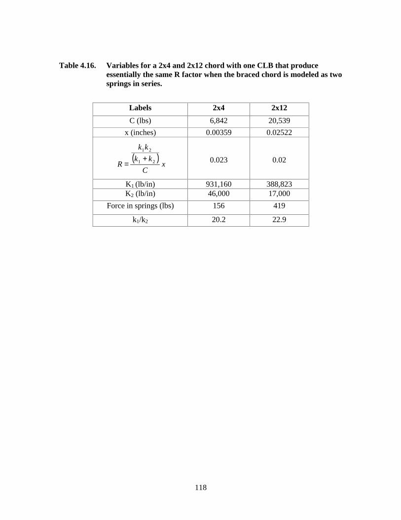
118
( )x
C
kk
kk
R 21
21
+=
Table 4.16. Variables for a 2x4 and 2x12 chord with one CLB that produceessentially the same R factor when the braced chord is modeled as twosprings in series.
Labels 2x4 2x12
C (lbs) 6,842 20,539
x (inches) 0.00359 0.02522
0.023 0.02
K1 (lb/in) 931,160 388,823K2 (lb/in) 46,000 17,000
Force in springs (lbs) 156 419
k1/k2 20.2 22.9

119
NLtruss = R * C
Step 3. Determine the net lateral restraining force, NL, required for j-trusses.
NL = j * NLtruss
Step 4. Determine the brace force in the diagonal, BFdiagonal, based on theta (θ)
and NL.
BFdiagonal = NL / cos θ
Note: The connection is typically between the diagonal brace and the truss chord
as illustrated in Figure 4.5 when lumber is used for both CLB’s and diagonal
braces.
For two out of three cases studied, a rational calculation based procedure sure as the
NDS-97 could not be used to design the connections between the diagonal and the truss
chords. When a rational procedure sure as the NDS-97 fails to yield a design that can be
constructed, the connections must be designed using professional judgement or be based
on proven experience with similar truss configurations. The design solution to this
problem may be to simply specify properly nailed sheathing in place of CLB’s and
diagonals. When sheathing is used, provisions must be made to allow for proper
ventilation.
4.6.2 Case II – Two diagonal braces in a V-shape
For Case II, two diagonal braces forming a V-shape extend from the ends of the
compression chord section to be braced to the middle of the compression chord as
depicted in Figure 1.3.
Step 1. Assume j-trusses will be braced by two diagonal braces in a V-shape
as a starting point for the design of the diagonals.
Step 2. Determine NLtruss using the R-values found in this research and C, the design
axial compression load in the chord) that can be obtained from the truss design
drawing, or from the Truss Designer.
NLtruss = R * C
Step 4. Determine the brace force in the diagonals, BFdiagonal, based on theta (θ)
and NL.

120
Figure 4.5. When lumber is used for both the CLB’s and the diagonals, thediagonals are connected to the top compression chord on the oppositeof the CLB’s.
CLB
Diagonal
Truss Top
Chord

121
BFdiagonal = (NL / cos θ )/2
Step 3. Determine the net lateral restraining force, NL, required for j-trusses.
NL = j * NLtruss
Note: The connection is typically between the diagonal brace and the truss chord
as illustrated in Figure 4.5 when lumber is used for both CLB’s and diagonal
braces.
The connections between the diagonal and the truss chords, should be designed using the
NDS-97 when possible, however this approach may lead to more nails being required in
the joint than can be installed. Professional judgement or a design based on proven
experience with similar truss configurations may be required. The design solution to this
problem may be to simply specify properly nailed sheathing in place of CLB’s and
diagonals. When sheathing is used, provisions must be made to allow for proper
ventilation.
4.7 System Versus Single Member Analogs
The system analogs analyzed as discussed in Section 3.5 were limited in number
compared to the single member analogs analyzed and discussed in Section 3.6. To
compare the lateral bracing forces from the system analog and the single member
analogs, the proposed design procedure was used to determine the net lateral restraining
forces for the single member analogs. Using the design procedure and the R-value
determined after the SAP2000 (CSI, 1995) analysis, the net lateral restraining force (NL)
needed to stabilize j-truss chords could be determined. The single member analogs
neglected the slip between the diagonal and the chords and was based on the assumption
that the behavior of n-chords tied together by CLB’s could be predicted by analyzing one
chord and multiplying the bracing forces obtained by n. Therefore, in comparing the
single member to the system analogs, required net lateral bracing forces were tabulated
for the system analogs and compared to the net lateral bracing force determined by the
proposed design procedure for the same number of trusses.

122
The chords, assumed to be located parallel to y-axis of a coordinate system, are laterally
stabilized by the x-component of the joint force developed at each diagonal and chord
connection. The required net lateral restraining force was calculated for the case of five
eight-foot chords braced by three CLB’s, six twenty-foot truss chords braced by nine
CLB’s, and eleven twenty-foot truss chords braced by nine CLB’s. The net force was
used in the calculation because some of the x-components of the joint forces are to the
left and some are to the right.
4.7.1 Comparison of Required NL for Five Eight-foot Truss Chords
To calculate the required NL using the SAP2000 (CSI, 1995) analysis results for five
2x4, eight-foot truss chords braced by three CLB’s and one diagonal, the x-components
of the joint force between each diagonal and truss chord (tabulated in Appendix C) was
summed taking into account the direction of the force. When the spring pushes to the left,
the force was assumed to be positive and when the spring is pushing right, the force was
assumed to be negative. When the truss chords were loaded with an axial load of 684
pounds, at Joint A (Figure 3.5) an x-component of –38 pounds exists but the force is not a
lateral bracing force because the truss is laterally stabilized by the roof diaphragm at that
point. The joint force of –38 pounds at Joint A stems from the compression of the chord
due to the axial chord load. At Joints B, C, and D (Figure 3.5), the x-components were –
29, -41, and –21 pounds, respectively. The x-components at Joints B, C, and D represent
forces required to laterally stabilize the chords. At Joint E (Figure 3.5), a reaction point
simulating the action of the diaphragm, the x-component of the joint force was equal to
129 pounds. This force is equal and opposite to the vector sum of the x-components at
Joints A, B, C, and D.
To determine the net lateral restraining force for comparison to the single member
analogs, the x-components at Joints B, C, and D were summed for each of the five
assumed chord load levels and are given in Table 4.17. By inspecting Table 4.17, the
bracing forces predicted by the single member analogs are a conservative estimate of the
bracing forces predicted by the system analogs by approximately five to six percent.

123
Table 4.17 The lateral forces calculated using the design procedure for the singlemember analog compared to the system analogs for five-eight foottrusses braced by three CLB’s and one diagonal brace
Applied compressive force 10-50% of allowable
(lbs)
684 1368 2053 2737 3421
Single member netlateral force (lbs)
96 192 287 383 479
System net lateralforce (lbs)
91 182 272 363 453
Single Member NLSystem NL
1.05 1.05 1.06 1.06 1.06

124
4.7.2 Comparison of Required NL for Six Twenty-foot Truss Chords
To calculate the required NL using the SAP2000 (CSI, 1995) analysis results for six 2x4,
twenty-foot truss chords braced by nine CLB’s and two diagonals, the x-components of
the joint force between each diagonal and truss chord (tabulated in Appendix C) was
summed taking into account the direction of the force as discussed in Section 4.7.1.
When the truss chords were loaded with an axial load of 684 pounds, at Joints A and
L(Figure 3.9) an x-component of 62 pounds exists but the force is not a lateral bracing
force because the truss is laterally stabilized by the roof diaphragm at that point. The
joint force of 62 pounds at Joints A and L stems from the compression of the chord due to
the axial chord load. At Joints B through K (Figure 3.9), the x-components were -2, -14,
–17, -22, -7, -7, -22, -17, -14, and -2 pounds, respectively. The x-components at Joints B
through K represent forces required to laterally stabilize the chords. Referring to Figure
3.9, the x-component of the joint force at Joints B through K stabilizes the chord.
Through equilibrium, the sum of the x-components of the joint force of Joints B through
K was simply equal to two times the x-component of the joint force at Joint A or Joint J
(due to symmetry either joint may be used).
To determine the net lateral restraining force for comparison to the single member
analogs, the x-components at Joints B through K were summed for each assumed chord
load level and are given in Table 4.18. By inspecting Table 4.18, the bracing forces
predicted by the single member analogs are a conservative estimate of the bracing forces
predicted by the system analogs starting at two percent and increasing as the load level
was increased.
4.7.3 Comparison of Required NL for Eleven Twenty-foot Truss Chords
To calculate the required NL using the SAP2000 (CSI, 1995) analysis results for eleven
2x4, twenty-foot truss chords braced by nine CLB’s and two diagonals, the x-components
of the joint force between each diagonal and truss chord (tabulated in Appendix C) was
summed taking into account the direction of the force as discussed in Section 4.7.1.
When the truss chords were loaded with an axial load of 684 pounds, at Joints A and L
(Figure 3.12) an x-component of 110 pounds exists but the force is not a lateral bracing

125
Table 4.18 The lateral forces calculated using the design procedure for the singlemember analog compared to the system analogs for six-twenty foottrusses braced by nine CLB’s and two diagonal braces
Applied compressive force 10-50% of allowable
(lbs)
684 1368 2053 2737 3421
Single member netlateral force (lbs)
127 254 382 509 636
System net lateralforce (lbs)
124 247 367 486 602
Single Member NLSystem NL
1.02 1.03 1.04 1.05 1.06

126
force for the same reasons discussed in Section 4.7.2. At Joints B through K (Figure
3.12), the x-components were 2, -28, –33, -37, -15, -15, -38, -32, -28, and 2 pounds,
respectively. The x-components at Joints B through K represent forces required to
laterally stabilize the chords. Referring to Figure 3.12, the x-component of the joint force
at Joints B through K stabilizes the chord. Through equilibrium, the sum of the x-
components of the joint force of Joints B through K was simply equal to two times the x-
component of the joint force at Joint A or Joint J (due to symmetry either joint may be
used).
To determine the net lateral restraining force for comparison to the single member
analogs, the x-components at Joints B through K were summed and are given in Table
4.19. By inspecting Table 4.19, the bracing forces predicted by the single member
analogs are a conservative estimate of the bracing forces predicted by the system analogs
starting at five percent and increasing as the load level was increased.

127
Table 4.19 The lateral forces calculated using the design procedure for the singlemember analog compared to the system analogs for eleven-twentyfoot trusses braced by nine CLB’s and two diagonal braces
Applied compressive force 10-50% of allowable
(lbs)
684 1368 2053 2737 3421
Single member netlateral force (lbs)
233 466 700 933 1167
System net lateralforce (lbs)
221 434 637 824 983
Single Member NLSystem NL
1.05 1.07 1.1 1.13 1.19

128
5.0 Conclusions
5.1 System and Single Member Analogs
Analyses on systems of roof truss chords braced by n-CLB’s and one or two diagonal
brace(s) was implemented in SAP2000 (CSI, 1995). Systems of five eight-foot truss
chords braced by three CLB’s and one diagonal, six twenty-foot truss chords braced by
nine CLB’s and two diagonals, and eleven twenty-foot truss chords braced by nine CLB’s
and two diagonals were analyzed. For each of the three cases analyzed, the chord lumber
was assumed to be 2x4 No. 2 Southern Pine (S. Pine) braced by 2x4 STUD Spruce-Pine-
Fir (SPF). Chord load levels of 10% to 50% of the allowable load were studied.
For the case of five eight-foot trusses braced by three CLB’s and one diagonal brace, the
single member analog estimate of the required net lateral bracing forces was
approximately five to six percent greater than the estimate of the required net lateral
bracing forces predicted by the system analog analysis. For the case of six twenty-foot
trusses braced by nine CLB’s and two diagonal braces and chord load levels of 10% to
50% of the allowable load, the single member analog estimate of the required NL was
two percent or more greater than the estimate of the required NL predicted by the system
analog analysis. For the case of eleven twenty-foot trusses braced by nine CLB’s and
two diagonal braces and chord load levels of 10% to 50% of the allowable load, the
single member analog estimate of the system required NL was five percent or more
greater than the bracing force from the system analog analysis.
For the three cases studied, with chord loads from 10 to 50% of the allowable Fc’, the
predicted net lateral bracing force by the single member analysis was greater than the
bracing force predicted by the system analog analysis. Based on the three cases studied
involving 2x4 chords braced as a unit (and believed to be representative of typical truss
construction), the bracing force from the single member analog analysis was a
conservative estimate for bracing design purposes. Based on other single member studies
in this thesis that showed chord size and chord lumber did not affect bracing forces, it is

129
concluded that the single member analysis analog will yield approximate bracing forces
for chords greater than 2x4 and for typical constructions beyond the three cases studied in
this research. It is believed that the presence of a diagonal brace(s) stiffens the braced set
of j-chords and thereby reduces the net lateral force required to brace the j-chords
compared to the required bracing force from the single member analysis. It is not
practical to attempt to analyze all possible combinations of truss lumber and bracing
scenarios (n-chords braced either by a V-diagonal or a single diagonal, and all possible
spans and chord load levels).
5.2 One Web Braced with One CLB
A linear beam model a with non-linear spring connection at the brace point was used to
represent one web braced by one CLB. By assuming 2x4 STUD Spruce-Pine-Fir (SPF)
for roof truss webs up to twelve feet in length and braced with one SPF CLB utilizing a
2-16d Common nail connection, the net lateral restraining force from the SAP2000 (CSI,
1995) analysis was 0.023 or 2.3% of the web compression web.
When designing braces for j-webs in a row, the required net lateral restraining force, NL,
for j-webs braced with one CLB can be calculated by:
NL = j * 2.3% * axial force in web
where, j is the number of webs in a row having the same design axial load.
NL is input to the proposed design method in Section 4.6.
Since nail slip data was available for a Douglas Fir-Larch joint, the structural analog was
analyzed assuming a No. 2 Douglas Fir-Larch web and Douglas Fir-Larch CLB. Douglas
Fir-Larch has a specific gravity of 0.5 versus 0.42 of SPF. Douglas Fir-Larch also has a
17% higher modulus of elasticity, E, than SPF. This case examined the effect of higher
specific gravity on the nail slip and resulting net lateral restraining forces. Based on the
net lateral restraining forces obtained during the SAP2000 (CSI, 1995) analyses, for
design purposes, it is reasonable to assume 2.3% is applicable to species having a specific
gravity greater than 0.42.

130
The lumber size was also varied in order to test the impact of lumber size on the net
lateral restraining forces produced during analysis. Based on the SAP2000 (CSI, 1995)
analyses, for design purposes, it is reasonable to assume 2.3% is also applicable to a 2x6
web.
5.3 One web Braced with Two CLB’s
A linear beam model with non-linear springs representing the behavior of the CLB
connections was used to analyze the case of one web braced by two CLB’s. By assuming
STUD Spruce-Pine-Fir (SPF) for 2x4 roof truss webs up to fifteen feet in length and
braced with two 2x4 SPF CLB’s connected to the web with 2-16d Common nail
connections, the net lateral restraining force from the SAP2000 (CSI, 1995) analysis was
0.028 or 2.8% of the web compression web.
When designing braces for j-webs in a row, the required net lateral restraining force, NL,
for j-webs braced by two CLB’s can be calculated:
NL = j * 2.8% * axial force in web
where, j is the number of webs in a row having the same design axial load.
NL is input to the proposed design method in Section 4.6.
Since nail slip data was available for a Douglas Fir-Larch joint, the structural analog was
analyzed assuming a No. 2 Douglas Fir-Larch web and Douglas Fir-Larch CLB’s.
Douglas Fir-Larch has a specific gravity of 0.5 versus 0.42 of SPF. Douglas Fir-Larch
also has a 17% higher modulus of elasticity, E, than SPF. This case examined the effect
of higher specific gravity on the nail slip and resulting net lateral restraining forces.
Based on the net lateral restraining forces obtained during the SAP2000 (CSI, 1995)
analyses, for design purposes, it is reasonable to assume 2.8% is applicable to species
having a specific gravity greater than 0.42.
The lumber size was also varied in order to test the impact of lumber size on the net
lateral restraining forces produced during analysis. Based on the SAP2000 (CSI, 1995)

131
analyses, for design purposes, it is reasonable to assume 2.8% is also applicable to a 2x6
web.
5.4 Roof Truss Chord braced by n-CLB’s
A linear beam model was used to represent one roof truss chord that required n-CLB’s.
The nail connections between the CLB’s and the chord were modeled by a non-linear
spring. The structural analog was created assuming No. 2 Southern Pine chords braced
by 2x4 Spruce-Pine-Fir CLB’s (specific gravity equal to 0.42). In calculating the slip of
the 2-16d Common nail connections, it was assumed that both the chord and the CLB
were SPF because nail slip data was not available for a joint having mixed species.
By assuming No. 2 Southern Pine (2x4 to 2x12) truss chords ranging from four feet to
forty feet length and braced with n-Spruce-Pine-Fir CLB’s at two feet on-center each
installed with 2-16d Common nails, the net lateral restraining force from the SAP2000
(CSI, 1995) analysis was found to be a maximum of 3.1% of the compression force in the
chord. Peak value of 3.1% occurred at chord lengths of sixteen feet to thirty-two feet.
Chord lengths shorter than sixteen feet required a lower net lateral restraining force.
Chords longer than thirty-two feet required a lower net lateral restraining force because
TPI’s installation tolerances as provided in DSB-89 (TPI, 1989) were assumed for the
maximum initial deflections for the chords.
When designing permanent bracing for j-chords in a row, the required net lateral
restraining force, NL, for j-chords braced by n-CLB’s can be approximated by:
NL = j * R * axial force in chord
where j is the number of truss chords in a row having the same design axial load, and
R is the ratio between the net lateral bracing force (lbs) and the axial load level in
the web/chord (lbs), for design purposes. An R-value of 3.1% is conservative with
respect to the variable chord length since for chord lengths between four and forty-feet
evaluated using the single member analog, it was the maximum R-value obtained. NL is
then input to the proposed bracing design method given in Section 4.6.

132
For a specific design, Tables 4.11 through 4.15, can be used in place of the conservative
R-value equal to 3.1% of the axial compression load in the truss chord.

133
References
Alpine Engineered Products, Inc. 1996. Handling, Installing and BracingMetal Plate Connected Wood Trusses (Video). Alpine Engineered Products,Pompano Beach, Florida.
American Forest & Paper Association (AF&PA). 1997. ANSI/AF&PA NDS-1997National Design Specification for Wood Construction. AF&PA, Washington, D.C.
ANSYS, Inc. 1997. ANSYS. Version 5.4. Canonsburg, PA.
Chen, W.F. and Liu, E.M. 1987. Structural Stability: Theory and Implementation.Elsevier Science Publishing Co., Inc., New York, NY.
Computer and Structures, Inc. (CSI). 1995. SAP2000 Analysis Reference. Volume 1.CSI, Berkeley, CA.
International Conference of Building Officials. 1994. Uniform Building Code. Volume2, Structural Engineering Provisions. ICBO, 5360 Workman Mill Road, Whittier, CA90601.
Kagan, Harvey A. 1993. Common Causes of Collapse of Metal-Plate-Connected WoodRoof Trusses. Journal of Performance of Constructed Facilities, 7(4): 225-234.
Mack, J.J. 1966. The Strength and Stiffness of Nailed Joints under Short-DurationLoading. CSIRO Forest Products Paper #40: 28.
Meeks, John. 1998. Wood Truss Installation Considerations: Temporary Bracing. WoodDesign & Building. Number 5: 39-42.
_______. 1999. Commentary for Permanent Bracing of Metal Plate Connected WoodTruss. Wood Truss Council of America. Madison, WI.
Nair, R.S. 1992. Forces on Bracing Systems. Engineering Journal of the AmericanInstitute of Steel Construction, (29)1: 45-47.
Plaut, R.H., and Yang, J.G. 1993. Lateral Bracing Forces in Columns with Two UnequalSpans. Journal of Structural Engineering, ASCE, 119(10): 2896-2912.
Plaut, R.H. 1993. Requirements for lateral bracing of columns with two spans. ASCEJournal of Structural Engineering. 119(10): 2913-2931.
Plaut, R.H., and Yang, J.W. (1995). Behavior of Three-Span Braced Columns withEqual or Unequal Spans. Journal of Structural Engineering, ASCE, 121(6): 986-994.

134
_______. 1995. Behavior of Three-span Braced Columns with Equal or Unequal Spans.ASCE Journal of Structural Engineering. 121(6): 986-994.
Smith, J.C. 1991. Structural Steel Design LRFD Approach. John Wiley & Sons, Inc.,New York, NY.
Smith, J.C. 1996. Structural Steel Design LRFD Approach. 2nd edition. John Wiley &Sons, Inc., New York, NY.
Smith, J.G. 1999. Temporary Truss Bracing For Post Frame. Frame Building News11(1): 58-60.
South African Bureau of Standards. 1994. South African Standard Code of Practice Thestructural use of timber Part 2: Allowable stress design. South African Bureau ofStandards, Pretoria, Republic of South Africa.
Throop, C.M. 1947. Suggestions for Safe Lateral Bracing Design. Engineering NewsRecord, 6 February 1947: 90-91.
Timoshenko, S. and Gere, James. 1961. Theory of Elastic Stability. McGraw-Hill BookCompany, Inc., New York, NY.
Truss Plate Institute (TPI). 1989. DSB-89 Recommended Design Specification forTemporary Bracing of Metal Plate Connected Wood Trusses. Truss Plate Institute,Madison, WI.
_______. 1991a. Commentary and Recommendations for Handling, Installing & BracingMetal Plate Connected Wood Trusses (HIB-91 Pocketbook). Truss Plate Institute,Madison, WI.
_______. 1991b. HIB-91 Summary Sheet: Commentary and Recommendations forHandling, Installing & Bracing Metal Plate Connected Wood Trusses. Truss PlateInstitute, Madison, WI.
_______. 1995. ANSI/TPI 1-1995 National Design Standard for Metal Plate ConnectedWood Truss Construction. Truss Plate Institute, Madison, WI.
_______. 1998. HIB-98 Post–Frame Summary Sheet: Recommendation for Handling,Installing, & Temporary Bracing Metal Plate Connected Wood Trusses used in Post-Frame Construction. Truss Plate Institute, Madison, WI.
Tsien, H. S. 1942. Buckling of a column with nonlinear lateral supports. Journal of theAeronautical Sciences. 9(4): 119-32.
Vogt, Jim and Smith, Rachel. 1999. Wood Truss Installation Considerations: PermanentBracing. Wood Design & Building. Number 6: 40-42.

135
Walpole and Myers. 1993. Probability and Statistics for Engineers and Scientists. 5th
ed. Prentice Hall, Englewood Cliffs, NJ.
Waltz, Miles E. 1998. Discrete Compression Web Bracing Design for Light-FrameWood Trusses. MS Thesis, Oregon State University, Corvallis, Oregon.
Winter, G. 1960. Lateral Bracing of Columns and Beams. Transactions of the ASCE.Volume 125: 807-845
Woeste, F.E. 1998. Permanent Bracing for Piggy-back Trusses. Journal of LightConstruction. 16(6): 79-83.
Wood Truss Council of America (WTCA). 1995. WTCA 1-1995 StandardResponsibilities in the Design Process Involving Metal Plate Connected Wood Trusses.Wood Truss Council of America, Madison, WI.
Yura, Joseph. A. 1996. Winter’s bracing approach revisited. Engineering Structures.18(10): 821-825.
Zuk, William. 1956. Lateral Bracing Forces on Beams and Columns. Journal of theEngineering Mechanics Division of the American Society of Civil Engineers. ProceedingsPaper No. 1032. 82(EM3): 1032-1 to 1032-16.

136
( )506.25
5.12
12*88.0*8.0 <==
d
L
( )( ) 549
6.25
10*2.13.0’2
6
2==
=
d
l
EKF
e
CECE
c
F
F
c
F
F
c
F
F
C C
CE
C
CE
C
CE
P
−
+
−
+
=*
2
**
2
1
2
1
Appendix A
Sample calculations to determine Fc’ for use in SAP2000 (CSI, 1995)analysis
The following analysis was used to determine the allowable axial compressive loads for
the web/chord members. The analysis was based on the procedure outlined in the NDS
97 (AF&PA, 1997). The example given was calculated for a eight foot long, 2x4, STUD
Spruce-Pine-Fir web.
F’c (A) = allowable load
Fc’ = Fc * CD * CP * CF
Fc = 725 psi (Fc, page 29, NDS 97 supplement)
E = 1.2 x 10⁶ (E, page 29, NDS 97 supplement)
CD = 1.15
CF = 1.05
le/d = o.k.
Fc* = Fc * CD * CF = 725 * 1.15 * 1.05 = 875
(KCE, page 22, NDS 97)
FCE / FC* = 549 / 875 = 0.627
(CP, page 22, NDS 97)

137
( ) ( ) ( )8.0
627.0
8.0*2
627.01
8.0*2
627.012
−
+−+=PC
c = 0.8 for sawn lumber (c, page 22, NDS 97)
CP = 1.017 – 0.5003 = 0.5167
FC’ = 725 * 1.15 * 0.5167 * 1.05 = 452 psi
FC’ * A = 468 psi * 1.5 inches * 3.5 inches = 2375 lbs.
The maximum allowable axial compressive load for a eight foot long, 2x4, STUD
Spruce-Pine-Fir web was 2,375 pounds.

138
Appendix B
Spring forces produced in the chord and CLB nail connections inSAP2000 (CSI, 1995) for Southern Pine Chords braced by n-Spruce-Pine-Fir webs for a single member analysis
Table B1. Spring forces (lbs) produced in the chord and CLB nail connections inSAP2000 (CSI, 1995) for a 2x4 No. 2 Southern Pine chord braced byn-Spruce-Pine-Fir CLB’s connected by a 2-16d Common nailconnections.
Axial load in compression chord, Fc’ (lbs)
Length (ft) 684 1368 2053 2737 3421 4105 4790 5474 6158 6842
4 15.72 15.73 31.46 31.45 47.21 47.07 62.76 62.71 78.39 78.29 93.95 93.91 109.6 109.4 125.1 125 140.7 140.6 156.2 155.6
6 9.49 9.49 18.99 18.99 28.49 28.49 37.99 37.98 47.47 47.46 56.95 56.95 66.45 66.44 75.93 75.92 85.41 85.4 94.88 94.88
9.49 9.49 18.99 18.99 28.49 28.49 37.99 37.98 47.47 47.46 56.95 56.95 66.45 66.44 75.93 75.92 85.41 85.4 94.88 94.88
8 5.69 5.7 11.39 11.39 17.1 17.1 22.79 22.79 28.49 28.49 34.23 34.25 39.96 39.92 45.62 45.77 51.49 51.34 57.04 57.08
7.99 7.98 15.95 15.95 23.94 23.94 31.92 31.92 39.89 39.84 47.81 47.78 55.75 55.8 63.77 63.56 71.5 71.72 79.68 79.6
5.69 5.7 11.39 11.39 17.1 17.1 22.79 22.79 28.49 28.49 34.23 34.25 39.96 39.92 45.62 45.77 51.49 51.34 57.04 57.08
12 2.74 2.74 5.47 5.47 8.21 8.22 10.96 10.96 13.69 13.69 16.42 16.43 19.17 19.16 21.9 21.9 24.63 24.64 27.38 27.37
4.78 4.79 9.57 9.57 14.37 14.36 19.14 19.14 23.93 23.95 28.73 28.73 33.52 33.53 38.32 38.32 43.11 43.09 47.88 47.92
5.48 5.47 10.94 10.94 16.42 16.43 21.9 21.9 27.38 27.35 32.82 32.83 38.31 38.3 43.77 43.77 49.23 49.25 54.72 54.66
4.78 4.79 9.57 9.57 14.37 14.36 19.14 19.14 23.93 23.95 28.73 28.73 33.52 33.53 38.32 38.32 43.11 43.09 47.88 47.92
2.74 2.74 5.47 5.47 8.21 8.22 10.96 10.96 13.69 13.69 16.42 16.43 19.17 19.16 21.9 21.9 24.63 24.64 27.38 27.37
16 1.57 1.57 3.14 3.14 4.71 4.71 6.27 6.27 7.84 7.84 9.41 9.41 10.98 10.99 12.56 12.56 14.13 14.13 15.69 15.69
2.96 2.96 5.93 5.93 8.89 8.89 11.86 11.85 14.82 14.82 17.79 17.8 20.77 20.74 23.71 23.71 26.67 26.67 29.63 29.64
3.85 3.85 7.69 7.69 11.55 11.55 15.4 15.41 19.26 19.26 23.09 23.07 26.92 26.95 30.8 30.8 34.65 34.65 38.49 38.5
4.16 4.16 8.32 8.32 12.49 12.49 16.65 16.63 20.79 20.79 24.96 24.98 29.15 29.13 33.29 33.29 37.45 37.45 41.61 41.6
3.85 3.85 7.69 7.69 11.55 11.55 15.4 15.41 19.26 19.26 23.09 23.07 26.92 26.95 30.8 30.8 34.65 34.65 38.49 38.5
2.96 2.96 5.93 5.93 8.89 8.89 11.86 11.85 14.82 14.82 17.79 17.8 20.77 20.74 23.71 23.71 26.67 26.67 29.63 29.64
1.57 1.57 3.14 3.14 4.71 4.71 6.27 6.27 7.84 7.84 9.41 9.41 10.98 10.99 12.56 12.56 14.13 14.13 15.69 15.69
20 1.05 1.05 2.11 2.11 3.16 3.16 4.22 4.22 5.27 5.27 6.32 6.32 7.38 7.38 8.43 8.43 9.49 9.48 10.54 10.54
1.94 1.94 3.88 3.88 5.82 5.82 7.76 7.76 9.7 9.7 11.64 11.64 13.58 13.58 15.52 15.52 17.46 17.47 19.41 19.41
2.76 2.76 5.53 5.53 8.3 8.3 11.06 11.06 13.82 13.82 16.59 16.59 19.35 19.35 22.12 22.12 24.88 24.86 27.62 27.62
3.1 3.1 6.21 6.21 9.32 9.32 12.42 12.42 15.53 15.53 18.63 18.63 21.74 21.74 24.85 24.85 27.95 28 31.11 31.11
3.42 3.42 6.85 6.85 10.27 10.27 13.7 13.7 17.12 17.12 20.54 20.54 23.97 23.97 27.4 27.4 30.82 30.75 34.17 34.17
3.1 3.1 6.21 6.21 9.32 9.32 12.42 12.42 15.53 15.53 18.63 18.63 21.74 21.74 24.85 24.85 27.95 28 31.11 31.11
2.76 2.76 5.53 5.53 8.3 8.3 11.06 11.06 13.82 13.82 16.59 16.59 19.35 19.35 22.12 22.12 24.88 24.86 27.62 27.62
1.94 1.94 3.88 3.88 5.82 5.82 7.76 7.76 9.7 9.7 11.64 11.64 13.58 13.58 15.52 15.52 17.46 17.47 19.41 19.41
1.05 1.05 2.11 2.11 3.16 3.16 4.22 4.22 5.27 5.27 6.32 6.32 7.38 7.38 8.43 8.43 9.49 9.48 10.54 10.54
24 0.74 0.74 1.48 1.48 2.22 2.22 2.96 2.96 3.7 3.7 4.44 4.44 5.19 5.19 5.93 5.93 6.67 6.67 7.41 7.41
1.34 1.34 2.68 2.68 4.02 4.02 5.36 5.36 6.7 6.7 8.04 8.04 9.38 9.38 10.72 10.72 12.06 12.06 13.4 13.4
2 2 3.99 3.99 5.99 5.99 7.99 7.99 9.98 9.98 11.98 11.98 13.98 13.98 15.97 15.97 17.97 17.97 19.97 19.97
2.56 2.56 5.13 5.12 7.69 7.69 10.25 10.25 12.81 12.81 15.37 15.37 17.94 17.94 20.5 20.5 23.06 23.06 25.63 25.63

139
Table B1 continued. Spring forces (lbs) produced in the chord and CLB nail connections in SAP2000 (CSI, 1995) for a 2x4 No. 2 Southern Pine chord braced by n-Spruce-Pine-Fir CLB’s connected by a2-16d Common nail connections.
Axial load in compression chord, Fc’ (lbs)
Length (ft) 684 1368 2053 2737 3421 4105 4790 5474 6158 6842
2.57 2.57 5.13 5.14 7.71 7.71 10.28 10.28 12.85 12.85 15.42 15.42 17.99 17.99 20.56 20.56 23.13 23.13 25.7 25.7
2.85 2.85 5.7 5.69 8.54 8.54 11.39 11.39 14.23 14.23 17.08 17.08 19.93 19.93 22.77 22.77 25.62 25.62 28.47 28.47
2.57 2.57 5.13 5.14 7.71 7.71 10.28 10.28 12.85 12.85 15.42 15.42 17.99 17.99 20.56 20.56 23.13 23.13 25.7 25.7
2.56 2.56 5.13 5.12 7.69 7.69 10.25 10.25 12.81 12.81 15.37 15.37 17.94 17.94 20.5 20.5 23.06 23.06 25.63 25.63
2 2 3.99 3.99 5.99 5.99 7.99 7.99 9.98 9.98 11.98 11.98 13.98 13.98 15.97 15.97 17.97 17.97 19.97 19.97
1.34 1.34 2.68 2.68 4.02 4.02 5.36 5.36 6.7 6.7 8.04 8.04 9.38 9.38 10.72 10.72 12.06 12.06 13.4 13.4
0.74 0.74 1.48 1.48 2.22 2.22 2.96 2.96 3.7 3.7 4.44 4.44 5.19 5.19 5.93 5.93 6.67 6.67 7.41 7.41

140
Table B2. Spring forces (lbs) produced in the chord and CLB nail connections inSAP2000 (CSI, 1995) for a 2x6 No. 2 Southern Pine chord braced byn-Spruce-Pine-Fir CLB’s connected by 2-16d Common nailconnections.
Axial load in compression chord, Fc’ (lbs)
Length (ft) 1059 2117 3176 4235 5294 6352 7411 8470 9529 10587
4 24.18 24.22 48.25 48.34 72.24 72.38 96.2 96.33 120.1 120.3 143.7 144 167.5 167.7 191 191.4 214.5 214.9 239.7 238.3
6 14.69 14.69 29.36 29.36 44.05 44.03 58.74 58.7 73.38 73.35 88.01 87.99 102.7 102.7 117.3 117.3 132 131.9 146.6 146.5
14.69 14.69 29.36 29.36 44.05 44.03 58.74 58.7 73.38 73.35 88.01 87.99 102.7 102.7 117.3 117.3 132 131.9 146.6 146.5
8 8.83 8.82 17.65 17.66 26.47 26.49 35.34 35.3 44.24 44.17 53.09 53.09 61.98 61.98 70.81 70.84 79.7 79.67 88.4 88.55
12.32 12.35 24.64 24.64 36.98 36.96 49.25 49.31 61.46 61.56 73.73 73.74 85.95 86.02 98.26 98.23 110.5 110.5 123 122.8
8.83 8.82 17.65 17.66 26.47 26.49 35.34 35.3 44.24 44.17 53.09 53.09 61.98 61.94 70.81 70.84 79.7 79.67 88.4 88.55
12 4.24 4.24 8.47 8.47 12.71 12.71 16.96 16.94 21.22 21.2 25.46 25.46 29.74 29.7 33.95 33.99 38.22 38.19 42.35 42.47
7.41 7.41 14.82 14.82 22.23 22.23 29.63 29.64 37.01 37.04 44.42 44.41 51.77 51.82 59.27 59.16 66.65 66.68 74.17 74.05
8.47 8.47 16.93 16.93 25.39 25.39 33.86 33.86 42.36 42.33 50.81 50.83 59.34 59.28 67.68 67.81 76.16 76.14 84.53 84.62
7.41 7.41 14.82 14.82 22.23 22.23 29.63 29.64 37.01 37.04 44.42 44.42 51.77 51.82 59.27 59.16 66.65 66.68 74.17 74.05
4.24 4.24 8.47 8.47 12.71 12.71 16.96 16.94 21.22 21.2 25.46 25.46 29.74 29.7 33.95 33.99 38.22 38.19 42.35 42.47
16 2.43 2.43 4.85 4.85 7.28 7.28 9.71 9.7 12.12 12.12 14.55 14.55 16.97 17 19.43 19.42 21.84 21.85 24.28 24.28
4.59 4.59 9.17 9.17 13.76 13.76 18.35 18.37 22.97 22.98 27.57 27.57 32.16 32.11 36.7 36.71 41.3 41.28 45.86 45.86
5.96 5.96 11.91 11.91 17.87 17.87 23.82 23.8 29.75 29.73 35.67 35.67 41.62 41.68 47.63 47.63 53.59 53.65 59.61 59.61
6.44 6.44 12.88 12.88 19.32 19.32 25.76 25.78 32.23 32.24 38.69 38.69 45.13 45.08 51.52 51.52 57.96 57.86 64.29 64.29
5.96 5.96 11.91 11.91 17.87 17.87 23.82 23.8 29.75 29.73 35.67 35.67 41.62 41.68 47.63 47.63 53.59 53.65 59.61 59.61
4.59 4.59 9.17 9.17 13.76 13.76 18.35 18.37 22.97 22.98 27.57 27.57 32.16 32.11 36.7 36.71 41.3 41.28 45.86 45.86
2.43 2.43 4.85 4.85 7.28 7.28 9.71 9.7 12.12 12.12 14.55 14.55 16.97 17 19.43 19.42 21.84 21.85 24.28 24.28
20 1.63 1.63 3.26 3.26 4.89 4.89 6.52 6.52 8.15 8.15 9.78 9.78 11.42 11.41 13.04 13.05 14.68 14.68 16.31 16.3
3 3 6 6 9.01 9.01 12.01 12.01 15.01 15.01 18.01 18.01 21.01 21.04 24.04 24.03 27.04 27.05 30.05 30.06
4.27 4.27 8.55 8.55 12.82 12.82 17.09 17.11 21.39 21.39 25.66 25.66 29.94 29.89 34.17 34.18 38.45 38.43 42.7 42.68
4.82 4.82 9.63 9.63 14.44 14.44 19.26 19.24 24.06 24.06 28.86 28.86 33.68 33.72 38.54 38.53 43.35 43.37 48.19 48.21
5.29 5.29 10.57 10.57 15.86 15.86 21.15 21.16 26.45 26.45 31.73 31.73 37.03 36.98 42.27 42.27 47.55 47.54 52.82 52.8
4.82 4.82 9.63 9.63 14.44 14.44 19.26 19.24 24.06 24.06 28.86 28.86 33.68 33.72 38.54 38.53 43.35 43.37 48.19 48.21
4.27 4.27 8.55 8.55 12.82 12.82 17.09 17.11 21.39 21.39 25.66 25.66 29.94 29.89 34.17 34.18 38.45 38.43 42.7 42.68
3 3 6 6 9.01 9.01 12.01 12.01 15.01 15.01 18.01 18.01 21.01 21.04 24.04 24.03 27.04 27.05 30.05 30.06
1.63 1.63 3.26 3.26 4.89 4.89 6.52 6.52 8.15 8.15 9.78 9.78 11.42 11.41 13.04 13.05 14.68 14.68 16.31 16.3
24 1.15 1.15 2.29 2.29 3.44 3.44 4.58 4.58 5.73 5.73 6.88 6.88 8.02 8.02 9.17 9.19 10.33 10.33 11.48 11.47
2.07 2.07 4.14 4.14 6.22 6.22 8.29 8.29 10.36 10.36 12.43 12.43 14.5 14.5 16.58 16.57 18.64 18.64 20.71 20.72
3.1 3.1 6.19 6.19 9.28 9.28 12.38 12.38 15.48 15.48 18.57 18.57 21.67 21.67 24.76 24.75 27.85 27.85 30.94 30.94
3.96 3.96 7.91 7.91 11.87 11.87 15.83 15.83 19.79 19.79 23.74 23.74 27.7 27.69 31.65 31.67 35.63 35.63 39.58 39.56
3.99 3.99 7.97 7.97 11.96 11.96 15.94 15.94 19.93 19.93 23.91 23.91 27.9 27.92 31.91 31.89 35.87 35.87 39.86 39.91
4.4 4.4 8.79 8.79 13.19 13.19 17.58 17.58 21.98 21.98 26.37 26.37 30.77 30.74 35.13 35.16 39.55 39.55 43.94 43.87
3.99 3.99 7.97 7.97 11.96 11.96 15.94 15.94 19.93 19.93 23.91 23.91 27.9 27.92 31.91 37.89 35.87 35.87 39.86 39.91
3.96 3.96 7.91 7.91 11.87 11.87 15.83 15.83 19.79 19.79 23.74 23.74 27.7 27.69 31.65 31.67 35.63 35.63 39.58 39.56
3.1 3.1 6.19 6.19 9.28 9.28 12.38 12.38 15.48 15.48 18.57 18.57 21.67 21.67 24.76 24.75 27.85 27.85 30.94 30.94
2.07 2.07 4.14 4.14 6.22 6.22 8.29 8.29 10.36 10.36 12.43 12.43 14.5 14.5 16.58 16.57 16.64 16.64 20.71 20.72
1.15 1.15 2.29 2.29 3.44 3.44 4.58 4.58 5.73 5.73 6.88 6.88 8.02 8.02 9.17 9.19 10.33 10.33 11.48 11.47
28 0.83 0.83 1.67 1.67 2.5 2.5 3.34 3.34 4.17 4.17 5.01 5.01 5.84 5.84 6.68 6.68 7.52 7.52 8.35 8.35
1.51 1.51 3.02 3.02 4.53 4.53 6.03 6.03 7.54 7.54 9.04 9.04 10.56 10.56 12.07 12.07 13.56 13.56 15.08 15.08
2.68 2.68 5.36 5.36 8.04 8.04 10.72 10.72 13.4 13.4 16.1 16.1 18.76 18.76 21.46 21.46 24.15 24.14 26.02 26.02

141
Table B2 continued. Spring forces (lbs) produced in the chord and CLB nail connections in SAP2000 (CSI, 1995) for a 2x6 No. 2 Southern Pine chord braced by n-Spruce-Pine-Fir CLB’s connected by 2-16d Common nail connections.
Axial load in compression chord, Fc’ (lbs)
Length (ft) 1059 2117 3176 4235 5294 6352 7411 8470 9529 10587
2.65 2.65 5.31 5.31 7.96 7.96 10.61 10.61 13.27 13.27 15.9 15.9 18.57 18.57 21.2 21.2 23.86 23.87 26.52 26.52
3.09 3.09 6.18 6.18 9.28 9.28 12.37 12.37 15.46 15.46 18.53 18.53 21.65 21.65 24.79 24.79 27.83 27.82 30.91 30.91
3.96 3.96 7.91 7.91 11.88 11.88 15.83 15.83 19.8 19.8 23.76 23.76 27.72 27.72 31.68 31.68 35.64 35.64 39.32 39.32
3.55 3.55 7.09 7.09 10.62 10.62 14.18 14.18 17.7 17.7 21.24 21.24 24.78 24.78 28.33 28.33 31.87 31.88 35.42 35.42
3.96 3.96 7.91 7.91 11.88 11.88 15.83 15.83 19.8 19.8 23.76 23.76 27.72 27.72 31.68 31.68 35.64 35.64 39.32 39.32
3.09 3.09 6.18 6.18 9.28 9.28 12.37 12.37 15.46 15.46 18.53 18.53 21.65 21.65 24.74 24.74 27.83 27.82 30.91 30.91
2.65 2.65 5.31 5.31 7.96 7.96 10.61 10.61 13.27 13.27 15.9 15.9 18.57 18.57 21.2 21.2 23.86 23.87 26.52 26.52
2.68 2.68 5.36 5.36 8.04 8.04 10.72 10.72 13.4 13.4 16.1 16.1 18.76 18.76 21.46 21.46 24.15 24.14 26.02 26.02
1.51 1.51 3.02 3.02 4.53 4.53 6.03 6.03 7.54 7.54 9.04 9.04 10.56 10.56 12.07 12.07 13.56 13.56 15.08 15.08
0.83 0.83 1.67 1.67 2.5 2.5 3.34 3.34 4.17 4.17 5.01 5.01 5.84 5.84 6.68 6.68 7.52 7.52 8.35 8.35
32 0.65 0.65 1.32 1.32 1.97 1.97 2.63 2.63 3.29 3.29 3.95 3.95 4.61 4.61 5.27 5.27 5.92 5.92 6.58 6.58
1.11 1.11 2.22 2.22 3.33 3.33 4.44 4.44 5.55 5.55 6.66 6.66 7.77 7.77 8.88 8.88 9.99 9.99 11.1 11.1
1.97 1.97 3.95 3.95 5.92 5.92 7.9 7.9 9.88 9.88 11.85 11.85 13.83 13.83 15.8 15.8 17.78 17.76 19.73 19.73
2.22 2.22 4.44 4.44 6.66 6.66 8.87 8.87 11.09 11.09 13.31 13.31 15.53 15.53 17.75 17.75 19.97 20 22.23 22.23
3.07 3.07 6.14 6.14 9.22 9.22 12.29 12.29 15.37 15.37 18.44 18.44 21.51 21.51 24.59 24.59 27.66 27.61 30.67 30.67
2.66 2.66 5.31 5.31 7.97 7.97 10.63 10.63 13.29 13.29 15.94 15.94 18.6 18.6 21.26 21.26 23.92 23.95 26.61 26.61
3.09 3.09 6.17 6.17 9.26 9.26 12.35 12.35 15.43 15.43 18.52 18.52 21.61 21.61 24.69 24.69 27.78 27.79 30.88 30.88
3.53 3.53 7.05 7.05 10.58 10.58 14.1 14.1 17.63 17.63 21.15 21.15 24.68 24.68 28.2 28.2 31.73 31.69 35.21 35.21
3.09 3.09 6.17 6.17 9.26 9.26 12.35 12.35 15.43 15.43 18.52 18.52 21.61 21.61 24.69 24.69 27.78 27.79 30.88 30.88
2.66 2.66 5.31 5.31 7.97 7.97 10.63 10.63 13.29 13.29 15.94 15.94 18.6 18.6 21.26 21.26 23.92 23.95 26.61 26.61
3.07 3.07 6.14 6.14 9.22 9.22 12.29 12.29 15.37 15.37 18.44 18.44 21.51 21.51 24.59 24.59 27.66 27.61 30.67 30.67
2.22 2.22 4.44 4.44 6.66 6.66 8.87 8.87 11.09 11.09 13.31 13.31 15.53 15.53 17.75 17.75 19.97 20 22.23 22.23
1.97 1.97 3.95 3.95 5.92 5.92 7.9 7.9 9.88 9.88 11.85 11.85 13.83 13.83 15.8 15.8 17.78 17.76 19.73 19.73
1.11 1.11 2.22 2.22 3.33 3.33 4.44 4.44 5.55 5.55 6.66 6.66 7.77 7.77 8.88 8.88 9.99 9.99 11.1 11.1
0.65 0.65 1.32 1.32 1.97 1.97 2.63 2.63 3.29 3.29 3.95 3.95 4.61 4.61 5.27 5.27 5.92 5.92 6.58 6.58
36 0.44 0.44 0.881 0.881 1.32 1.32 1.76 1.76 2.2 2.2 2.64 2.64 3.09 3.09 3.53 3.53 3.97 3.97 4.41 4.41
0.927 0.927 1.85 1.85 2.78 2.78 3.71 3.71 4.63 4.63 5.56 5.56 6.49 6.49 7.41 7.41 8.34 8.34 9.27 9.27
1.32 1.32 2.65 2.65 3.97 3.97 5.3 5.3 6.62 6.62 7.94 7.94 9.27 9.27 10.59 10.59 11.91 11.91 13.24 13.24
1.76 1.76 3.53 3.53 5.29 5.29 7.05 7.05 8.82 8.82 10.58 10.58 12.34 12.34 14.11 14.11 15.87 15.87 17.63 17.63
2.03 2.03 4.06 4.06 6.09 6.09 8.12 8.12 10.16 10.16 12.18 12.18 14.22 14.22 16.25 16.25 18.28 18.28 20.31 20.31
2.34 2.34 4.67 4.67 7.01 7.01 9.34 9.34 11.68 11.68 14.01 14.01 16.35 16.35 18.69 18.69 21.02 21.02 23.36 23.36
2.47 2.47 4.95 4.95 7.42 7.42 9.89 9.89 12.37 12.37 14.84 14.84 17.31 17.31 19.79 19.79 22.26 22.26 24.73 24.73
2.69 2.69 5.37 5.37 8.06 8.06 10.75 10.75 13.44 13.44 16.13 16.13 18.81 18.81 21.5 21.5 24.19 24.19 26.88 26.88
2.65 2.65 5.3 5.3 7.95 7.95 10.6 10.6 13.25 13.25 15.9 15.9 18.55 18.55 21.2 21.2 23.85 23.85 26.5 26.5
2.69 2.69 5.37 5.37 8.06 8.06 10.75 10.75 13.44 13.44 16.13 16.13 18.81 18.81 21.5 21.5 24.19 24.19 26.88 26.88
2.47 2.47 4.95 4.95 7.42 7.42 9.89 9.89 12.37 12.37 14.84 14.84 17.31 17.31 19.79 19.79 22.26 22.26 24.73 24.73
2.34 2.34 4.67 4.67 7.01 7.01 9.34 9.34 11.68 11.68 14.01 14.01 16.35 16.35 18.69 18.69 21.02 21.02 23.36 23.36
2.03 2.03 4.06 4.06 6.09 6.09 8.12 8.12 10.16 10.16 12.18 12.18 14.22 14.22 16.25 16.25 18.28 18.28 20.31 20.31
1.76 1.76 3.53 3.53 5.29 5.29 7.05 7.05 8.82 8.82 10.58 10.58 12.34 12.34 14.11 14.11 15.87 15.87 17.63 17.63
1.32 1.32 2.65 2.65 3.97 3.97 5.3 5.3 6.62 6.62 7.94 7.94 9.27 9.27 10.59 10.59 11.91 11.91 13.24 13.24
0.927 0.927 1.85 1.85 2.78 2.78 3.71 3.71 4.63 4.63 5.56 5.56 6.49 6.49 7.41 7.41 8.34 8.34 9.27 9.27
0.44 0.44 0.881 0.881 1.32 1.32 1.76 1.76 2.2 2.2 2.64 2.64 3.09 3.09 3.53 3.53 3.97 3.97 4.41 4.41

142
Table B3. Spring forces (lbs) produced in the chord and CLB nail connections inSAP2000 (CSI, 1995) for a 2x8 No. 2 Southern Pine chord braced byn-Spruce-Pine-Fir CLB’s connected by 2-16d Common nailconnections.
Axial load in compression chord, Fc’ (lbs)
Length (ft) 1373 2746 4118 5491 6864 8237 9609 10982 12355 13728
4 31.3 31.3 62.6 62.3 93.43 93.22 124.3 124 155 154.7 185.6 184.8 215.6 214.9 245.7 245.2 275.8 274.8 305.4 304.4
6 19.03 19.03 38.05 38.05 57.06 57.03 76.05 76.01 95.02 94.99 114 114 132.9 132.9 151.8 151.8 170.8 170.8 189.7 189.6
19.03 19.03 38.05 38.05 57.06 57.03 76.05 76.01 95.02 94.99 114 114 132.9 132.9 151.8 151.8 170.8 170.8 189.7 189.6
8 11.43 11.43 22.86 22.91 34.36 34.35 45.81 45.95 57.44 57.29 68.75 68.85 80.32 80.3 91.78 91.9 103.4 103.6 115.1 115.3
16.01 16.01 32.02 31.93 47.89 47.89 63.86 63.63 79.54 79.73 95.68 95.53 111.4 111.5 127.4 127.2 143.1 142.8 158.7 158.4
11.43 11.43 22.86 22.91 34.36 34.35 45.81 45.95 57.44 57.29 68.75 68.85 80.32 80.3 91.78 91.9 103.4 103.6 115.1 115.3
12 5.49 5.49 10.99 10.99 16.48 16.48 21.97 21.95 27.44 27.54 33.05 33.07 38.58 38.64 44.17 44.11 49.62 49.77 55.3 55.03
9.61 9.61 19.22 19.22 28.82 28.82 38.43 38.46 48.08 47.94 57.53 57.57 67.16 67.06 76.65 76.76 86.36 86.14 95.71 96.05
10.98 10.98 21.95 21.95 32.92 32.92 43.9 43.87 54.84 54.97 65.96 65.87 76.84 76.94 87.93 87.79 98.76 99 110 109.7
9.61 9.61 19.22 19.22 28.82 28.82 38.43 38.46 48.08 47.94 57.53 57.57 67.16 67.06 76.65 76.76 86.36 86.14 95.71 96.05
5.49 5.49 10.99 10.99 16.48 16.48 21.97 21.95 27.44 27.54 33.05 33.07 38.58 38.64 44.17 44.11 49.62 49.77 55.3 55.03
16 3.15 3.15 6.3 6.3 9.44 9.43 12.58 12.57 15.71 15.76 18.91 18.92 22.07 22.04 25.19 25.22 28.37 28.33 31.48 31.59
5.95 5.95 11.89 11.89 17.84 17.86 23.81 23.82 29.77 29.71 35.66 35.67 41.61 41.63 47.58 47.55 53.49 53.58 59.54 59.37
7.72 7.72 15.45 15.45 23.16 23.14 30.86 30.89 38.62 38.62 46.35 46.33 54.05 54.07 61.79 61.83 69.56 69.41 77.13 77.32
8.35 8.35 16.7 16.7 25.05 25.06 33.42 33.36 41.7 41.7 50.08 50.09 58.44 58.4 66.74 66.69 75.03 75.2 83.56 83.35
7.72 7.72 15.45 15.45 23.16 23.14 30.86 30.89 38.62 38.62 46.35 46.33 54.05 54.07 61.79 61.83 69.56 69.41 77.13 77.32
5.95 5.95 11.89 11.89 17.84 17.86 23.81 23.82 29.77 29.77 35.66 35.67 41.61 41.63 47.58 47.55 53.49 53.58 59.54 59.37
3.15 3.15 6.3 6.3 9.44 9.43 12.58 12.57 15.71 15.71 18.91 18.92 22.07 22.04 25.19 25.22 28.37 28.33 31.48 31.59
20 2.11 2.11 4.22 4.22 6.33 6.33 8.45 8.45 10.56 10.56 12.67 12.69 14.81 14.77 16.88 16.93 19.04 19.03 21.15 21.17
3.9 3.9 7.8 7.8 11.7 11.7 15.6 15.6 19.5 19.5 23.4 23.37 27.26 27.34 31.24 31.18 35.07 35.09 38.99 38.94
5.54 5.54 11.07 11.07 16.6 16.6 22.14 22.14 27.68 27.68 33.21 33.23 38.76 38.69 44.22 44.26 49.79 49.75 55.28 55.37
6.25 6.25 12.5 12.5 18.74 18.74 24.99 24.99 31.24 31.24 37.48 37.51 43.76 43.78 50.04 50.04 56.3 56.37 62.63 62.51
6.85 6.85 13.7 13.7 20.55 20.55 27.4 27.4 34.26 34.26 41.11 41.06 47.9 47.9 54.74 54.72 61.56 61.47 68.3 68.42
6.25 6.25 12.5 12.5 18.74 18.74 24.99 24.99 31.24 31.24 37.48 37.51 43.76 43.78 50.04 50.04 56.3 56.37 62.63 62.51
5.54 5.54 11.07 11.07 16.6 16.6 22.14 22.14 27.68 27.68 33.21 33.23 38.76 38.69 44.22 44.26 49.79 49.75 55.28 55.37
3.9 3.9 7.8 7.8 11.7 11.7 15.6 15.6 19.5 19.5 23.4 23.37 27.26 27.34 31.24 31.18 35.07 35.09 38.99 38.94
2.11 2.11 4.22 4.22 6.33 6.33 8.45 8.45 10.56 10.56 12.67 12.69 14.81 14.77 16.88 16.93 19.04 19.03 21.15 21.17
24 1.49 1.49 2.98 2.98 4.46 4.46 5.95 5.95 7.44 7.44 8.92 8.91 10.4 10.4 11.88 11.9 13.39 13.42 14.91 14.93
2.69 2.69 5.37 5.37 8.06 8.06 10.74 10.74 13.43 13.43 16.11 16.14 18.83 18.83 21.52 21.5 24.19 24.15 26.83 26.83
4.02 4.02 8.03 8.03 12.04 12.04 16.06 16.06 20.07 20.07 24.09 24.06 28.07 28.07 32.08 32.11 36.12 36.15 40.16 4.14
5.13 5.13 10.26 10.26 15.39 15.39 20.52 20.52 25.65 25.65 30.78 30.78 35.91 35.91 41.04 41 46.13 46.12 51.25 51.27
5.17 5.17 10.34 10.34 15.5 15.5 20.67 20.67 25.84 25.84 31.01 31.04 36.21 36.21 41.39 41.42 46.6 46.58 51.76 51.78
5.7 5.7 11.4 11.4 17.1 17.1 22.8 22.8 28.5 28.5 34.2 34.15 39.84 39.84 45.53 45.51 51.2 51.22 56.91 56.87
5.17 5.17 10.34 10.34 15.5 15.5 20.67 20.67 25.84 25.84 31.01 31.04 36.21 36.21 41.39 41.42 46.6 46.58 51.76 51.78
5.13 5.13 10.26 10.26 15.39 15.39 20.52 20.52 25.65 25.65 30.78 30.78 35.91 35.91 41.04 41 46.13 46.12 51.25 51.27
4.02 4.02 8.03 8.03 12.04 12.04 16.06 16.06 20.07 20.07 24.09 24.06 28.07 28.07 32.08 32.11 36.12 36.15 40.16 40.14
2.69 2.69 5.37 5.37 8.06 8.06 10.74 10.74 13.43 13.43 16.11 16.14 18.83 18.83 21.52 21.5 24.19 24.15 26.88 26.83
1.49 1.49 2.98 2.98 4.46 4.46 5.95 5.95 7.44 7.44 8.92 8.91 10.4 10.4 11.88 11.9 13.39 13.42 14.91 14.93
28 1.08 1.08 2.16 2.16 3.24 3.24 4.32 4.32 5.4 5.4 6.48 6.48 7.56 7.54 8.62 8.62 9.7 9.7 10.78 10.78
1.96 1.96 3.92 3.92 5.88 5.88 7.84 7.84 9.8 9.8 11.75 11.75 13.71 13.76 15.72 15.72 17.69 17.7 19.67 19.67
3.47 3.47 6.94 6.94 10.41 10.41 13.88 13.88 17.35 17.35 20.82 20.82 24.29 24.26 27.73 27.73 31.2 31.16 34.62 34.61
3.44 3.44 6.89 6.89 10.32 10.32 13.77 13.77 17.22 17.22 20.66 20.66 24.1 24.05 27.48 27.48 30.92 30.99 34.43 34.46

143
Table B3 continued. Spring forces (lbs) produced in the chord and CLB nail connections in SAP2000 (CSI, 1995) for a 2x8 No. 2 Southern Pine chord braced by n-Spruce-Pine-Fir CLB’s connected by 2-16d Common nail connections.
Axial load in compression chord, Fc’ (lbs)
Length (ft) 1373 2746 4118 5491 6864 8237 9609 10982 12355 13728
4.01 4.01 8.02 8.02 12.03 12.03 16.04 16.04 20.05 20.05 24.07 24.07 28.07 28.23 32.26 32.26 36.29 36.21 40.23 40.19
5.13 5.13 10.25 10.25 15.38 15.38 20.5 20.5 25.63 25.63 30.76 30.76 35.88 35.69 40.78 40.78 45.88 45.94 51.05 51.11
4.6 4.6 9.21 9.21 13.81 13.81 18.41 18.41 23.01 23.01 27.61 27.61 32.21 32.41 37.04 37.04 41.67 41.64 46.27 46.19
5.13 5.13 10.25 10.25 15.38 15.38 20.5 20.5 25.63 25.63 30.76 30.76 35.88 35.69 40.78 40.78 45.88 45.94 51.05 51.11
4.01 4.01 8.02 8.02 12.03 12.03 16.04 16.04 20.05 20.05 24.07 24.07 28.07 28.23 32.26 32.26 36.29 36.21 40.23 40.19
3.44 3.44 6.89 6.89 13.32 13.32 13.77 13.77 17.22 17.22 20.66 20.66 24.1 24.05 27.48 27.48 30.92 30.99 34.43 34.46
3.47 3.47 6.94 6.94 10.41 10.41 13.88 13.88 17.35 17.35 20.82 20.82 24.29 24.26 27.73 27.73 31.2 31.16 34.62 34.61
1.96 1.96 3.92 3.92 5.88 5.88 7.84 7.84 9.8 9.8 11.75 11.75 13.71 13.76 15.72 15.72 17.69 17.7 19.67 19.67
1.08 1.08 2.16 2.16 3.24 3.24 4.32 4.32 5.4 5.4 6.48 6.48 7.56 7.54 8.62 8.62 9.7 9.7 10.78 10.78
32 0.852 0.852 1.7 1.7 2.56 2.56 3.41 3.41 4.26 4.26 5.11 5.11 5.96 5.96 6.82 6.81 7.67 7.67 8.52 8.49
1.44 1.44 2.89 2.89 4.33 4.33 5.77 5.77 7.21 7.21 8.65 8.65 10.1 10.1 11.54 11.54 12.99 12.99 14.43 14.48
2.56 2.56 5.11 5.11 7.66 7.66 10.22 10.22 12.77 12.77 15.33 15.33 17.88 17.88 20.44 20.42 22.97 22.97 25.52 25.48
2.89 2.89 5.78 5.78 8.66 8.66 11.55 11.55 14.44 14.44 17.33 17.33 20.22 20.22 23.1 23.15 26.05 26.05 28.94 28.93
3.97 3.97 7.94 7.94 11.91 11.91 15.88 15.88 19.85 19.85 23.81 23.81 27.78 27.79 31.76 31.7 35.66 35.66 39.62 39.67
3.46 3.46 6.92 6.92 10.38 10.38 13.84 13.84 17.3 17.3 20.76 20.76 24.22 24.19 27.65 27.7 31.16 31.16 34.63 34.57
4 4 7.99 7.99 11.98 11.98 15.98 15.98 19.98 19.98 23.97 23.97 27.97 28.03 32.03 31.99 35.99 35.99 39.99 40.03
4.57 4.57 9.15 9.15 13.72 13.72 18.3 18.3 22.87 22.87 27.44 27.44 32.02 31.93 36.49 36.54 41.11 41.11 45.68 45.63
4 4 7.99 7.99 11.98 11.98 15.98 15.98 19.98 19.98 23.97 23.97 27.97 28.03 32.03 31.99 35.99 35.99 39.99 40.03
3.46 3.46 6.92 6.92 10.38 10.38 13.84 13.84 17.3 17.3 20.76 20.76 24.22 24.19 27.65 27.7 31.16 31.16 34.63 34.57
3.97 3.97 7.94 7.94 11.91 11.91 15.88 15.88 19.85 19.85 23.81 23.81 27.78 27.79 31.76 31.7 35.66 35.66 39.62 39.67
2.89 2.89 5.78 5.78 8.66 8.66 11.55 11.55 14.44 14.44 17.33 17.33 20.22 20.22 23.1 23.15 26.05 26.05 28.94 28.93
2.56 2.56 5.11 5.11 7.66 7.66 10.22 10.22 12.77 12.77 15.33 15.33 17.88 17.88 20.44 20.42 22.97 22.97 25.52 25.48
1.44 1.44 2.89 2.89 4.33 4.33 5.77 5.77 7.21 7.21 8.65 8.65 10.1 10.1 11.54 11.54 12.99 12.99 14.43 14.48
0.852 0.852 1.7 1.7 2.56 2.56 3.41 3.41 4.26 4.26 5.11 5.11 5.96 5.96 6.82 6.81 7.67 7.67 8.52 8.49
36 0.572 0.572 1.14 1.14 1.71 1.71 2.29 2.29 2.86 2.86 3.43 3.43 4 4 4.57 4.57 5.14 5.14 5.71 5.71
1.2 1.2 2.4 2.4 3.61 3.61 4.81 4.81 6.01 6.01 7.21 7.21 8.41 8.41 9.61 9.61 10.82 10.82 12.02 12.02
1.72 1.72 3.43 3.43 5.15 5.15 6.87 6.87 8.58 8.58 10.3 10.3 12.02 12.02 13.73 13.73 15.45 15.45 17.17 17.17
2.29 2.29 4.57 4.57 6.86 6.86 9.14 9.14 11.43 11.43 13.72 13.72 16 16 18.29 18.29 20.57 20.57 22.86 22.86
2.63 2.63 5.27 5.27 7.9 7.9 10.54 10.54 13.17 13.17 15.8 15.8 18.44 18.44 21.07 21.07 23.71 23.71 26.34 26.34
3.03 3.03 6.06 6.06 9.08 9.08 12.11 12.11 15.14 15.14 18.17 18.17 21.19 21.19 24.22 24.22 27.25 27.25 30.28 30.28
3.21 3.21 6.42 6.42 9.62 9.62 12.83 12.83 16.04 16.04 19.25 19.25 22.45 22.45 25.66 25.66 28.87 28.87 32.08 32.08
3.48 3.48 6.97 6.97 10.45 10.45 13.94 13.94 17.42 17.42 20.9 20.9 24.39 24.39 27.87 27.87 31.36 31.36 34.84 34.84
3.44 3.44 6.88 6.88 10.31 10.31 13.75 13.75 17.19 17.19 20.62 20.62 24.06 24.06 27.5 27.5 30.93 30.93 34.37 34.37
3.48 3.48 6.97 6.97 10.45 10.45 13.94 13.94 17.42 17.42 20.9 20.9 24.39 24.39 27.87 27.87 31.36 31.36 34.84 34.84
3.21 3.21 6.42 6.42 9.62 9.62 12.83 12.83 16.04 16.04 19.25 19.25 22.45 22.45 25.66 25.66 28.87 28.87 32.08 32.08
3.03 3.03 6.06 6.06 9.08 9.08 12.11 12.11 15.14 15.14 18.17 18.17 21.19 21.19 24.22 24.22 27.25 27.25 30.28 30.28
2.63 2.63 5.27 5.27 7.9 7.9 10.54 10.54 13.17 13.17 15.8 15.8 18.44 18.44 21.07 21.07 23.71 23.71 26.34 26.34
2.29 2.29 4.57 4.57 6.86 6.86 9.14 9.14 11.43 11.43 13.72 13.72 16 16 18.29 18.29 20.57 20.57 22.86 22.86
1.72 1.72 3.43 3.43 5.15 5.15 6.87 6.87 8.58 8.58 10.3 10.3 12.02 12.02 13.73 13.73 15.45 15.45 17.17 17.17
1.2 1.2 2.4 2.4 3.61 3.61 4.81 4.81 6.01 6.01 7.21 7.21 8.41 8.41 9.61 9.61 10.82 10.82 12.02 12.02
0.572 0.572 1.14 1.14 1.71 1.71 2.29 2.29 2.86 2.86 3.43 3.43 4 4 4.57 4.57 5.14 5.14 5.71 5.71

144
Table B4. Spring forces (lbs) produced in the chord and CLB nail connections inSAP2000 (CSI, 1995) for a 2x10 No. 2 Southern Pine chord braced byn-Spruce-Pine-Fir CLB’s connected by 2-16d Common nailconnections.
Axial load in compression chord, Fc’ (lbs)
Length (ft) 1721 3442 5163 6884 8604 10325 12046 13767 15488 17209
4 38.85 39.02 77.35 77.69 115.5 116 153.2 154 190.8 191.6 229 228.9 264.2 267.1 299.8 302 334.5 337.3 377.5 371.7
6 23.84 23.84 47.69 47.64 71.46 71.41 95.21 95.16 118.9 118.9 142.7 142.6 166.3 166.2 190 189.9 213.6 213.4 237.2 237
23.84 23.84 47.69 47.64 71.46 71.41 95.21 95.16 118.9 118.9 142.7 142.6 166.3 166.2 190 189.9 213.6 213.4 237.2 237
8 14.36 14.34 28.83 28.73 43.19 43.25 57.63 57.58 72.05 72.03 86.63 86.47 101.4 101.1 115.5 115.9 130.1 129.9 144.8 144.6
20 20.04 39.83 39.99 59.81 59.75 79.65 79.75 99.49 99.55 119.1 119.4 138.5 139 158.8 158.3 178.3 178.7 198 198.1
14.36 14.34 28.83 28.73 43.19 43.25 57.63 57.58 72.05 72.03 86.63 86.47 101.4 101.1 115.5 115.9 130.1 129.9 144.8 144.6
12 6.88 6.88 13.77 13.8 20.7 20.68 27.58 27.63 34.53 34.54 41.44 41.53 48.45 48.53 55.46 55.43 62.35 62.25 69.17 69.32
12.04 12.04 24.08 24.05 36.07 36.12 48.16 48.1 60.11 60.16 72.19 72.16 84.19 84.01 96.02 96.12 108.1 108.3 120.3 120.2
13.77 13.77 27.54 27.56 41.34 41.27 55.03 55.08 68.84 68.76 82.52 82.48 96.23 96.44 110.2 110.1 123.8 123.6 137.4 137.5
12.04 12.04 24.08 24.05 36.07 36.12 48.16 48.1 60.11 60.16 72.19 72.16 84.19 84.01 96.02 96.12 108.1 108.3 120.3 120.2
6.88 6.88 13.77 13.8 20.7 20.68 27.58 27.63 34.33 34.54 41.44 41.53 48.45 48.53 55.46 55.43 62.35 62.25 69.17 69.32
16 3.95 3.95 7.89 7.89 11.84 11.82 15.76 15.75 19.69 19.75 23.7 23.76 27.72 27.66 31.61 31.67 35.63 35.65 39.61 39.71
7.45 7.45 14.91 14.91 22.36 22.4 29.87 29.87 37.33 37.27 44.73 44.66 52.11 52.23 59.69 59.63 67.08 67.07 74.53 74.4
9.68 9.68 19.36 19.36 29.04 29.03 38.7 38.73 48.41 48.39 58.06 58.12 67.81 67.66 77.32 77.42 87.1 87.06 96.74 96.88
10.47 10.47 20.94 20.94 31.4 31.4 41.86 41.81 52.25 52.33 62.79 62.74 73.19 73.34 83.82 83.69 94.15 94.21 104.7 104.5
9.68 9.68 19.36 19.36 29.04 29.03 38.7 38.73 48.41 48.39 58.06 58.12 67.81 67.66 77.32 77.42 87.1 87.06 96.74 96.88
7.45 7.45 14.91 14.91 22.36 22.4 29.87 29.87 37.33 37.27 44.73 44.66 52.11 52.23 59.69 59.63 67.08 67.07 74.53 74.4
3.95 3.95 7.89 7.89 11.84 11.82 15.76 15.75 19.69 19.75 23.7 23.76 27.72 27.66 31.61 31.67 35.63 35.65 39.61 39.71
20 2.65 2.65 5.29 5.29 7.94 7.94 10.58 10.57 13.21 13.24 15.89 15.91 18.56 18.52 21.16 21.17 23.82 23.71 26.35 26.53
4.89 4.89 9.78 9.78 14.68 14.68 19.57 19.6 24.49 24.44 29.33 29.32 34.21 34.3 39.2 39.16 44.06 44.32 49.24 48.91
6.94 6.94 13.87 13.87 20.81 20.81 27.74 27.71 34.64 34.67 41.6 41.6 48.54 48.42 55.34 55.45 62.38 62.03 68.93 69.27
7.84 7.84 15.67 15.67 23.51 23.51 31.34 31.36 39.2 39.22 47.07 47.06 54.91 55.05 62.92 62.73 70.57 70.87 78.74 78.52
8.59 8.59 17.17 17.17 25.76 25.76 34.34 34.32 42.89 42.84 51.41 51.42 59.99 59.82 68.37 68.58 77.15 76.92 85.46 85.61
7.84 7.84 15.67 15.67 23.51 23.51 31.34 31.36 39.2 39.22 47.07 47.06 54.91 55.05 62.92 62.73 70.57 70.87 78.74 78.52
6.94 6.94 13.87 13.87 20.81 20.81 27.74 27.71 34.64 34.67 41.6 41.6 48.54 48.42 55.34 55.45 62.38 62.03 68.93 69.27
4.89 4.89 9.78 9.78 14.68 14.68 19.57 19.6 24.49 24.44 29.33 29.32 34.21 34.3 39.2 39.16 44.06 44.32 49.24 48.91
2.65 2.65 5.29 5.29 7.94 7.94 10.58 10.57 13.21 13.24 15.89 15.91 18.56 18.52 21.16 21.17 23.82 23.71 26.35 26.53
24 1.86 1.86 3.73 3.73 5.59 5.59 7.46 7.46 9.32 9.31 11.17 11.21 13.08 13.08 14.95 14.95 16.82 16.8 18.67 18.71
3.37 3.37 6.73 6.73 10.1 10.1 13.46 13.46 16.83 16.86 20.23 20.18 23.54 23.53 26.89 26.92 30.29 30.32 33.69 33.61
5.04 5.04 10.07 10.07 15.11 15.11 20.15 20.15 25.18 25.15 30.19 30.23 35.27 35.3 40.35 40.29 45.32 45.3 50.34 50.43
6.42 6.42 12.85 12.85 19.27 19.27 25.7 25.7 32.12 32.12 38.54 38.5 44.92 44.89 51.3 51.33 57.75 57.74 64.16 64.1
6.49 6.49 12.97 12.97 19.46 19.46 25.94 25.94 32.42 32.45 38.94 38.99 45.49 45.47 51.97 52.02 58.52 58.54 65.05 65.04
7.14 7.14 14.28 14.28 21.42 21.42 28.56 28.56 35.7 35.66 42.8 42.73 49.85 49.9 57.03 56.94 64.06 64.03 71.14 71.19
6.49 6.49 12.97 12.97 19.46 19.46 25.94 25.94 32.42 32.45 38.94 38.99 45.49 45.47 51.97 52.02 58.52 58.54 65.05 65.04
6.42 6.42 12.85 12.85 19.27 19.27 25.7 25.7 32.12 32.12 38.54 38.5 44.92 44.89 51.3 51.33 57.75 57.74 64.16 64.1
5.04 5.04 10.07 10.07 15.11 15.11 20.15 20.15 25.18 25.15 30.19 30.23 35.27 35.3 40.35 40.29 45.32 45.3 50.34 50.43
3.37 3.37 6.73 6.73 10.1 10.1 13.46 13.46 16.83 16.86 20.23 20.18 23.54 23.53 26.89 26.92 30.29 30.32 33.69 33.61
1.86 1.86 3.73 3.73 5.59 5.59 7.46 7.46 9.32 9.31 11.17 11.21 13.08 13.08 14.95 14.95 16.82 16.8 18.67 18.71
28 1.35 1.35 2.71 2.71 4.06 4.06 5.42 5.42 6.77 6.76 8.11 8.11 9.46 9.44 10.79 10.77 12.12 12.11 13.45 13.45
2.46 2.46 4.92 4.92 7.38 7.38 9.84 9.84 12.29 12.32 14.79 14.79 17.26 17.31 19.78 19.81 22.29 22.31 24.79 24.79
4.35 4.35 8.69 8.69 13.04 13.04 17.38 17.38 21.73 21.7 26.04 26.04 30.38 30.32 34.65 34.62 38.95 38.92 43.25 43.25
4.32 4.32 8.63 8.63 12.95 12.95 17.26 17.26 21.58 21.57 25.89 25.89 30.21 30.24 34.56 34.57 38.89 38.39 43.21 43.21
5.03 5.03 10.07 10.07 15.1 15.1 20.14 20.14 25.17 25.24 30.29 30.29 35.34 35.33 40.37 40.37 45.41 45.48 50.53 50.53
6.42 6.42 12.83 12.83 19.25 19.25 25.67 25.67 32.08 31.96 38.35 38.35 44.74 44.74 51.13 51.15 57.54 57.41 63.79 63.79
5.78 5.78 11.56 11.56 17.34 17.34 23.11 23.11 28.89 29.03 34.84 34.84 40.65 40.66 46.47 46.43 52.24 52.39 58.22 58.22

145
Table B4 continued. Spring forces (lbs) produced in the chord and CLB nail connections in SAP2000 (CSI, 1995) for a 2x10 No. 2 Southern Pine chord braced by n-Spruce-Pine-Fir CLB’s connected by 2-16d Common nail connections.
Axial load in compression chord, Fc’ (lbs)
Length (ft) 1721 3442 5163 6884 8604 10325 12046 13767 15488 17209
6.42 6.42 12.83 12.83 19.25 19.25 25.67 25.67 32.08 31.96 38.35 38.35 44.74 44.74 51.13 51.15 57.54 57.41 63.79 63.79
5.03 5.03 10.07 10.07 15.1 15.1 20.14 20.14 25.17 25.24 30.29 30.29 35.34 35.33 40.37 40.37 45.41 45.48 50.53 50.53
4.32 4.32 8.63 8.63 12.95 12.95 17.26 17.26 21.58 21.57 25.89 25.89 30.21 30.24 34.56 34.57 38.89 38.39 43.21 43.21
4.35 4.35 8.69 8.69 13.04 13.04 17.38 17.38 21.73 21.7 26.04 26.04 30.38 30.32 34.65 34.62 38.95 38.92 43.25 43.25
2.46 2.46 4.92 4.92 7.38 7.38 9.84 9.84 12.29 12.32 14.79 14.79 17.26 17.31 19.78 19.81 22.29 22.31 24.79 24.79
1.35 1.35 2.71 2.71 4.06 4.06 5.42 5.42 6.77 6.76 8.11 8.11 9.46 9.44 10.79 10.77 12.12 12.11 13.45 13.45
32 1.07 1.07 2.13 2.13 3.2 3.2 4.26 4.26 5.33 5.33 6.4 6.4 7.46 7.47 8.54 8.51 9.57 9.55 10.61 10.61
1.81 1.81 3.62 3.62 5.44 5.44 7.25 7.25 9.06 9.06 10.87 10.87 12.68 12.64 14.45 14.53 16.34 16.41 18.23 18.22
3.2 3.2 6.39 6.39 9.59 9.59 12.79 12.79 15.98 15.98 19.18 19.18 22.38 22.47 25.68 25.56 28.76 28.68 31.86 31.9
3.63 3.63 7.26 7.26 10.89 10.89 14.52 14.52 18.15 18.14 21.77 21.77 25.4 25.29 28.9 29.02 32.65 32.72 36.36 36.31
4.97 4.97 9.93 9.93 14.9 14.9 19.86 19.86 24.82 24.83 29.79 29.79 34.76 34.86 39.85 39.73 44.7 44.65 49.61 49.66
4.35 4.35 8.69 8.69 13.04 13.04 17.38 17.38 21.72 21.7 26.04 26.04 30.38 30.29 34.62 34.72 39.06 39.11 43.46 43.4
5.01 5.01 10.01 10.01 15.02 15.02 20.03 20.03 25.03 25.1 30.12 30.12 35.14 35.19 40.22 40.15 45.17 45.11 50.13 50.2
5.73 5.73 11.47 11.47 17.2 17.2 22.93 22.93 28.66 28.57 34.28 34.28 40 39.96 45.67 45.72 51.44 51.5 57.23 57.14
5.01 5.01 10.01 10.01 15.02 15.02 20.03 20.03 25.03 25.1 30.12 30.12 35.14 35.19 40.22 40.15 45.17 45.11 50.13 50.2
4.35 4.35 8.69 8.69 13.04 13.04 17.38 17.38 21.72 21.7 26.04 26.04 30.38 30.29 34.62 34.72 39.06 39.11 43.45 43.4
4.97 4.97 9.93 9.93 14.9 14.9 19.86 19.86 24.82 24.83 29.79 29.79 34.76 34.86 39.85 39.73 44.7 44.65 49.61 49.66
3.63 3.63 7.26 7.26 10.89 10.89 14.52 14.52 18.15 18.14 21.77 21.77 25.4 25.29 28.9 29.02 32.65 32.72 36.36 36.31
3.2 3.2 6.39 6.39 9.59 9.59 12.79 12.79 15.98 15.98 19.18 19.18 22.38 22.47 25.68 25.56 28.76 28.68 31.86 31.9
1.81 1.81 3.62 3.62 5.44 5.44 7.25 7.25 9.06 9.06 10.87 10.87 12.68 12.64 14.45 14.53 16.34 16.41 18.23 18.22
1.07 1.07 2.13 2.13 3.2 3.2 4.26 4.26 5.33 5.33 6.4 6.4 7.46 7.47 8.54 8.51 9.57 9.55 10.61 10.61
36 0.716 0.716 1.43 1.43 2.15 2.15 2.86 2.86 3.58 3.58 4.3 4.3 5.01 5.01 5.73 5.73 6.44 6.44 7.16 7.16
1.51 1.51 3.01 3.01 4.52 4.52 6.03 6.03 7.53 7.53 9.04 9.04 10.55 10.55 12.05 12.05 13.56 13.56 15.07 15.07
2.15 2.15 4.3 4.3 6.46 6.46 8.61 8.61 10.76 10.76 12.91 12.91 15.06 15.06 17.22 17.22 19.37 19.37 21.52 21.5
2.86 2.86 5.73 5.73 8.59 8.59 11.46 11.46 14.32 14.32 17.19 17.19 20.05 20.05 22.92 22.91 25.77 25.77 28.63 28.69
3.3 3.3 6.61 6.61 9.91 9.91 13.21 13.21 16.51 16.51 19.82 19.82 23.12 23.12 26.42 26.45 29.75 29.75 33.06 33
3.79 3.79 7.59 7.59 11.38 11.38 15.18 15.18 18.97 18.97 22.77 22.77 26.56 26.56 30.36 30.32 34.11 34.11 37.9 37.95
4.02 4.02 8.05 8.05 12.07 12.07 16.09 16.09 20.11 20.11 24.14 24.14 28.16 28.16 32.18 32.22 36.25 36.25 40.28 40.25
4.37 4.37 8.73 8.73 13.1 13.1 17.46 17.46 21.83 21.83 26.19 26.19 30.56 30.56 34.93 34.89 39.25 39.25 43.61 43.63
4.31 4.31 8.62 8.62 12.93 12.93 17.24 17.24 21.55 21.55 25.86 25.86 30.17 30.17 34.48 34.51 38.83 38.83 43.14 43.13
4.37 4.37 8.73 8.73 13.1 13.1 17.46 17.46 21.83 21.83 26.19 26.19 30.56 30.56 34.93 34.89 39.25 39.25 43.61 43.63
4.02 4.02 8.05 8.05 12.07 12.07 16.09 16.09 20.11 20.11 24.14 24.14 28.16 28.16 32.18 32.22 36.25 36.25 40.28 40.25
3.79 3.79 7.59 7.59 11.38 11.38 15.18 15.18 18.97 18.97 22.77 22.77 26.56 26.56 30.36 30.32 34.11 34.11 37.9 37.95
3.3 3.3 6.61 6.61 9.91 9.91 13.21 13.21 16.51 16.51 19.82 19.82 23.12 23.12 26.42 26.45 29.75 29.75 33.06 33
2.86 2.86 5.73 5.73 8.59 8.59 11.46 11.46 14.32 14.32 17.19 17.19 20.05 20.05 22.92 22.91 25.77 25.77 28.63 28.69
2.15 2.15 4.3 4.3 6.46 6.46 8.61 8.61 10.76 10.76 12.91 12.91 15.06 15.06 17.22 17.22 19.37 19.37 21.52 21.5
1.51 1.51 3.01 3.01 4.52 4.52 6.03 6.03 7.53 7.53 9.04 9.04 10.55 10.55 12.05 12.05 13.56 13.56 15.07 15.07
0.716 0.716 1.43 1.43 2.15 2.15 2.86 2.86 3.58 3.58 4.3 4.3 5.01 5.01 5.73 5.73 6.44 6.44 7.16 7.16
40 0.573 0.573 1.15 1.15 1.72 1.72 2.29 2.29 2.87 2.87 3.44 3.44 4.01 4.01 4.59 4.59 5.16 5.15 5.72 5.72
1.08 1.08 2.15 2.15 3.23 3.23 4.3 4.3 5.37 5.37 6.45 6.45 7.52 7.52 8.6 8.6 9.68 9.69 10.77 10.77
1.58 1.58 3.16 3.16 4.74 4.74 6.32 6.32 7.9 7.9 9.48 9.48 11.06 11.06 12.64 12.64 14.22 14.21 15.79 15.79
2.15 2.15 4.29 4.29 6.44 6.44 8.58 8.58 10.73 10.73 12.88 12.88 15.02 15.02 17.17 17.17 19.31 19.32 21.46 21.46
2.44 2.44 4.89 4.89 7.33 7.33 9.77 9.77 12.21 12.21 14.66 14.66 17.1 17.1 19.54 19.54 21.99 21.98 24.43 24.43
2.86 2.86 5.73 5.73 8.59 8.59 11.46 11.46 14.32 14.32 17.19 17.19 20.05 20.05 22.92 22.92 25.78 25.8 28.66 28.66
3.16 3.16 6.31 6.31 9.47 9.47 12.63 12.63 15.79 15.79 18.94 18.94 22.1 22.1 25.26 25.26 28.42 28.4 31.56 31.56

146
Table B4 continued. Spring forces (lbs) produced in the chord and CLB nail connections in SAP2000 (CSI, 1995) for a 2x10 No. 2 Southern Pine chord braced by n-Spruce-Pine-Fir CLB’s connected by 2-16d Common nail connections.
Axial load in compression chord, Fc’ (lbs)
Length (ft) 1721 3442 5163 6884 8604 10325 12046 13767 15488 17209
3.37 3.37 6.74 6.74 10.1 10.1 13.47 13.47 16.84 16.84 20.21 20.21 23.57 23.57 26.94 26.94 30.31 30.31 33.67 33.67
3.45 3.45 6.89 6.89 10.34 10.34 13.78 13.78 17.23 17.23 20.67 20.67 24.12 24.12 27.56 27.56 31.01 31.01 34.46 34.46
3.58 3.58 7.16 7.16 10.74 10.74 14.33 14.33 17.9 17.9 21.49 21.49 25.07 25.07 28.65 28.65 32.23 32.22 35.8 35.8
3.45 3.45 6.89 6.89 10.34 10.34 13.78 13.78 17.23 17.23 20.67 20.67 24.12 24.12 27.56 27.56 31.01 31.01 34.46 34.46
3.37 3.37 6.74 6.74 10.1 10.1 13.47 13.47 16.84 16.84 20.21 20.21 23.57 23.57 26.94 26.94 30.31 30.31 33.67 33.67
3.16 3.16 6.31 6.31 9.47 9.47 12.63 12.63 15.79 15.79 18.94 18.94 22.1 22.1 25.26 25.26 28.42 28.4 31.56 31.56
2.86 2.86 5.73 5.73 8.59 8.59 11.46 11.46 14.32 14.32 17.19 17.19 20.05 20.05 22.92 22.92 25.78 25.8 28.66 28.66
2.44 2.44 4.89 4.89 7.33 7.33 9.77 9.77 12.21 12.21 14.66 14.66 17.1 17.1 19.54 19.54 21.99 21.98 24.43 24.43
2.15 2.15 4.29 4.29 6.44 6.44 8.58 8.58 10.73 10.73 12.88 12.88 15.02 15.02 17.17 17.17 19.31 19.32 21.46 21.46
1.58 1.58 3.16 3.16 4.74 4.74 6.32 6.32 7.9 7.9 9.48 9.48 11.06 11.06 12.64 12.64 14.22 14.21 15.79 15.79
1.08 1.08 2.15 2.15 3.23 3.23 4.3 4.3 5.37 5.37 6.45 6.45 7.52 7.52 8.6 8.6 9.68 9.69 10.77 10.77
0.573 0.573 1.15 1.15 1.72 1.72 2.29 2.29 2.87 2.87 3.44 3.44 4.01 4.01 4.59 4.59 5.16 5.15 5.72 5.72

147
Table B5. Spring forces (lbs) produced in the chord and CLB nail connections inSAP2000 (CSI, 1995) for a 2x12 No. 2 Southern Pine chord braced byn-Spruce-Pine-Fir CLB’s connected by 2-16d Common nailconnections.
Axial load in compression chord, Fc’ (lbs)
Length (ft) 2054 4108 6162 8216 10270 12323 14377 16431 18485 20539
4 46.36 46.04 92.72 91.98 138 137.1 182.8 181.9 227.4 225.5 270.6 268.8 313.6 310.9 355.4 352.4 396.5 391.3 429.3 419.1
6 28.42 28.42 56.84 56.79 85.19 85.11 113.5 113.4 141.7 141.6 169.9 169.8 198.1 197.9 226.2 226 254.3 254 282.2 281.8
28.42 28.42 56.84 56.79 85.19 85.11 113.5 113.4 141.7 141.6 169.9 169.8 198.1 197.9 226.2 226 254.3 254 282.2 281.8
8 17.11 17.11 34.23 34.21 51.32 51.6 68.81 69.08 86.35 85.8 103 103.5 120.8 120.8 138.1 138.4 155.7 156.1 173.5 173.7
23.91 23.91 47.81 47.79 71.69 71.26 95.02 94.59 118.2 119 142.8 141.9 165.5 165.4 189 188.4 212 211.4 234.9 234.5
17.11 17.11 34.23 34.21 51.32 51.6 68.81 69.08 86.35 85.8 103 103.5 120.8 120.8 138.1 138.4 155.7 156.1 173.5 173.7
12 8.22 8.22 16.43 16.44 24.66 24.69 32.91 33.02 41.28 41.37 49.64 49.66 57.93 58.04 66.33 66.18 74.45 74.8 83.11 82.75
14.37 14.37 28.73 28.76 43.14 43.12 57.5 57.39 71.73 71.69 86.03 85.99 100.3 100.2 114.5 114.9 129.2 128.7 143 143.5
16.43 16.43 32.87 32.82 49.23 49.22 65.63 65.71 82.13 82.1 98.51 98.54 115 115.1 131.5 131.1 147.5 147.9 164.4 163.9
14.37 14.37 28.73 28.76 43.14 43.12 57.5 57.39 71.73 71.69 86.03 85.99 100.3 100.2 114.5 114.9 129.2 128.7 143 143.5
8.22 8.22 16.43 16.44 24.66 24.69 32.91 33.02 41.28 41.37 49.64 49.66 57.93 58.04 66.33 66.18 74.45 74.8 83.11 82.75
16 4.71 4.71 9.42 9.4 14.1 14.18 18.9 18.84 23.55 23.67 28.41 28.36 33.09 33.08 37.8 37.86 42.59 42.68 47.43 47.43
8.9 8.9 17.79 17.84 26.76 26.66 35.55 35.66 44.57 44.39 53.26 53.35 62.24 62.32 71.23 71.15 80.04 79.89 88.77 88.77
11.55 11.55 23.11 23.06 34.59 34.66 46.21 46.13 57.66 57.83 69.39 69.31 80.86 80.75 92.29 92.35 103.9 104.1 115.7 115.7
12.49 12.49 24.99 25.02 37.53 37.49 49.99 50.04 62.54 62.39 74.86 74.92 87.41 87.49 99.99 99.94 112.4 112.2 124.7 124.7
11.55 11.55 23.11 23.06 34.59 34.66 46.21 46.13 57.66 57.83 69.39 69.31 80.86 80.75 92.29 92.35 103.9 104.1 115.7 115.7
8.9 8.9 17.79 17.84 26.76 26.66 35.55 35.66 44.57 44.39 53.26 53.35 62.24 62.32 71.23 71.15 80.04 79.89 88.77 88.77
4.71 4.71 9.42 9.4 14.1 14.18 18.9 18.84 23.55 23.67 28.41 28.36 33.09 33.08 37.8 37.86 42.59 42.68 47.43 47.43
20 3.15 3.15 6.31 6.31 9.46 9.46 12.61 12.61 15.77 15.81 18.97 19 22.17 22.08 25.23 25.29 28.45 28.4 31.56 31.61
5.84 5.84 11.69 11.69 17.53 17.54 23.39 23.38 29.23 29.18 35.02 34.98 40.31 40.98 46.83 46.73 52.58 52.68 58.54 58.55
8.27 8.27 16.54 16.54 24.81 24.81 33.09 33.07 41.34 41.37 49.64 49.67 57.94 57.76 66.02 66.13 74.4 74.3 82.55 82.42
9.36 9.36 18.72 18.72 28.08 28.06 37.41 37.48 46.85 46.81 56.17 56.2 65.56 65.67 75.06 74.98 84.35 84.38 93.75 93.91
10.24 10.24 20.48 20.48 30.72 30.73 40.98 40.87 51.09 51.15 61.38 61.31 71.52 71.47 81.68 81.71 91.93 91.95 102.2 102
9.36 9.36 18.72 18.72 28.08 28.06 37.41 37.48 46.85 46.81 56.17 56.2 65.56 65.67 75.06 74.98 84.35 84.38 93.75 93.91
8.27 8.27 16.54 16.54 24.81 24.81 33.09 33.07 41.34 41.37 49.64 49.67 57.94 57.76 66.02 66.13 74.4 74.3 82.55 82.42
5.84 5.84 11.69 11.69 17.53 17.54 23.39 23.38 29.23 29.18 35.02 34.98 40.31 40.98 46.83 46.73 52.58 52.68 58.54 58.55
3.15 3.15 6.31 6.31 9.46 9.46 12.61 12.61 15.77 15.81 18.97 19 22.17 22.08 25.23 25.29 28.45 28.4 31.56 31.61
24 2.23 2.23 4.45 4.45 6.68 6.68 8.9 8.9 11.13 11.09 13.31 13.36 15.58 15.58 17.81 17.83 20.06 20.02 22.24 22.2
4.02 4.02 8.03 8.03 12.05 12.05 16.06 16.06 20.08 20.16 24.19 24.1 28.12 28.15 32.17 32.15 36.16 36.25 40.28 40.31
6.01 6.01 12.03 12.03 18.04 18.04 24.06 24.07 30.08 30 36 36.12 42.14 42.09 48.1 48.12 54.14 54.07 60.07 60.07
7.66 7.66 15.32 15.32 22.98 22.98 30.64 30.61 38.26 38.31 45.97 45.87 53.52 53.51 61.15 61.16 68.81 68.83 76.48 76.43
7.75 7.75 15.49 15.49 23.24 23.24 30.99 31.09 38.86 38.81 46.57 46.59 54.36 54.48 62.25 62.19 69.97 69.96 77.73 77.83
8.51 8.51 17.03 17.03 25.54 25.54 34.06 33.93 42.41 42.47 50.95 50.97 59.46 59.28 67.75 67.86 76.34 76.36 84.84 84.71
7.75 7.75 15.49 15.49 23.24 23.24 30.99 31.09 38.86 38.81 46.57 46.59 54.36 54.48 62.25 62.19 69.97 69.96 77.73 77.83
7.66 7.66 15.32 15.32 22.98 22.98 30.64 30.61 38.26 38.31 45.97 45.87 53.52 53.51 61.15 61.16 68.81 68.83 76.48 76.43
6.01 6.01 12.03 12.03 18.04 18.04 24.06 24.07 30.08 30 36 36.12 42.14 42.09 48.1 48.12 54.14 54.07 60.07 60.07
4.02 4.02 8.03 8.03 12.05 12.05 16.06 16.06 20.08 20.16 24.19 24.1 28.12 28.15 32.17 32.15 36.16 36.25 40.28 40.31
2.23 2.23 4.45 4.45 6.68 6.68 8.9 8.9 11.13 11.09 13.31 13.36 15.58 15.58 17.81 17.83 20.06 20.02 22.24 22.2
28 1.61 1.61 3.22 3.22 4.83 4.83 6.45 6.45 8.06 8.04 9.65 9.62 11.22 11.2 12.8 12.78 14.38 14.36 15.96 16.09
2.94 2.94 5.89 5.89 8.83 8.83 11.77 11.77 14.71 14.76 17.71 17.77 20.73 20.77 23.74 23.79 26.76 26.8 29.78 29.6
5.18 5.18 10.36 10.36 15.54 15.54 20.72 20.72 25.9 25.86 31.02 30.96 36.12 36.07 41.23 41.19 46.34 46.27 51.41 51.51
5.15 5.15 10.31 10.31 15.46 15.46 20.62 20.62 25.77 25.77 30.92 30.94 36.09 36.13 41.29 41.24 46.39 46.51 51.67 51.72
6.81 6.81 12.02 12.02 18.04 18.04 24.05 24.05 30.06 30.15 36.17 36.23 42.27 42.22 48.26 48.44 54.5 54.36 60.4 60.25

148
Table B5 continued. Spring forces (lbs) produced in the chord and CLB nail connections in SAP2000 (CSI, 1995) for a 2x12 No. 2 Southern Pine chord braced by n-Spruce-Pine-Fir CLB’s connected by 2-16d Common nail connections.
Axial load in compression chord, Fc’ (lbs)
Length (ft) 2054 4108 6162 8216 10270 12323 14377 16431 18485 20539
7.65 7.65 15.3 15.3 22.95 22.95 30.6 30.6 38.25 38.11 45.73 45.61 53.21 53.28 60.89 60.62 68.19 68.32 75.92 76.11
6.91 6.91 13.81 13.81 20.72 20.72 27.63 27.63 34.53 34.7 41.63 41.77 48.73 48.64 55.59 55.9 62.88 62.76 69.74 69.53
7.65 7.65 15.3 15.3 22.95 22.95 30.6 30.6 38.25 38.11 45.73 45.61 53.21 53.28 60.89 60.62 68.19 68.32 75.92 76.11
6.81 6.81 12.02 12.02 18.04 18.04 24.05 24.05 30.06 30.15 36.17 36.23 42.27 42.22 48.26 48.44 54.5 54.36 60.4 60.25
5.15 5.15 10.31 10.31 15.46 15.46 20.62 20.62 25.77 25.77 30.92 30.94 36.09 36.13 41.29 41.24 46.39 46.51 51.67 51.72
5.18 5.18 10.36 10.36 15.54 15.54 20.72 20.72 25.9 25.86 31.02 30.96 36.12 36.07 41.23 41.19 46.34 46.27 51.41 51.51
2.94 2.94 5.89 5.89 8.83 8.83 11.77 11.77 14.71 14.76 17.71 17.77 20.73 20.77 23.74 23.79 26.76 26.8 29.78 29.6
1.61 1.61 3.22 3.22 4.83 4.83 6.45 6.45 8.06 8.04 9.65 9.62 11.22 11.2 12.8 12.78 14.38 14.36 15.96 16.09
32 1.27 1.27 2.54 2.54 3.81 3.81 5.08 5.08 6.35 6.36 7.63 7.63 8.9 8.85 10.12 10.1 11.36 11.37 12.63 12.6
2.17 2.17 4.33 4.33 6.5 6.5 8.66 8.66 10.83 10.81 12.98 12.95 15.11 15.25 17.42 17.46 19.65 19.62 21.8 21.88
3.81 3.81 7.63 7.63 11.44 11.44 15.26 15.26 19.07 19.09 22.9 22.95 26.77 26.59 30.39 30.34 34.13 34.18 37.98 37.84
4.33 4.33 8.65 8.65 12.98 12.98 17.31 17.31 21.63 21.66 25.99 25.94 30.27 30.42 34.76 34.82 39.18 39.13 43.48 43.66
5.94 5.94 11.88 11.88 17.82 17.82 23.75 23.75 29.69 29.62 35.54 35.55 41.48 41.39 47.31 47.24 53.15 53.16 59.07 58.89
5.17 5.17 10.33 10.33 15.5 15.5 20.67 20.67 25.83 25.92 31.1 31.1 36.28 36.32 41.51 41.55 46.75 46.74 51.93 52.07
6 6 12.01 12.01 18.01 18.01 24.01 24.01 30.01 29.94 35.93 35.94 41.93 41.93 47.92 47.94 53.93 53.96 59.95 59.87
6.81 6.81 13.62 13.62 20.43 20.43 27.24 27.24 34.05 34.11 40.93 40.92 47.74 47.71 54.53 54.48 61.29 61.25 68.06 68.12
6 6 12.01 12.01 18.01 18.01 24.01 24.01 30.01 29.94 35.93 35.94 41.93 41.93 47.92 47.94 53.93 53.96 59.95 59.87
5.17 5.17 10.33 10.33 15.5 15.5 20.67 20.67 25.83 25.92 31.1 31.1 36.28 36.32 41.51 41.55 46.75 46.74 51.93 52.07
5.94 5.94 11.88 11.88 17.82 17.82 23.75 23.75 29.69 29.62 35.54 35.55 41.48 41.39 47.31 47.24 53.15 53.16 59.07 58.89
4.33 4.33 8.65 8.65 12.98 12.98 17.31 17.31 21.63 21.66 25.99 25.94 30.27 30.42 34.76 34.82 39.18 39.13 43.48 43.66
3.81 3.81 7.63 7.63 11.44 11.44 15.26 15.26 19.07 19.09 22.9 22.95 26.77 26.59 30.39 30.34 34.13 34.18 37.98 37.84
2.17 2.17 4.33 4.33 6.5 6.5 8.66 8.66 10.83 10.81 12.98 12.95 15.11 15.25 17.42 17.46 19.65 19.62 21.8 21.88
1.27 1.27 2.54 2.54 3.81 3.81 5.08 5.08 6.35 6.36 7.63 7.63 8.9 8.85 10.12 10.1 11.36 11.37 12.63 12.6
36 0.855 0.855 1.71 1.71 2.56 2.56 3.42 3.42 4.27 4.27 5.13 5.13 5.98 5.98 6.84 6.84 7.69 7.7 8.55 8.55
1.8 1.8 3.6 3.6 5.4 5.4 7.2 7.2 8.99 8.99 10.79 10.79 12.59 12.59 14.39 14.39 16.19 16.16 17.96 17.94
2.57 2.57 5.14 5.14 7.71 7.71 10.27 10.27 12.84 12.84 15.41 15.41 17.98 17.98 20.55 20.55 23.12 23.18 25.76 25.78
3.42 3.42 6.84 6.84 10.26 10.26 13.67 13.67 17.09 17.09 20.51 20.51 23.93 23.92 27.34 27.34 30.76 30.68 34.09 34.08
3.94 3.94 7.89 7.89 11.83 11.83 15.77 15.77 19.72 19.72 23.66 23.66 27.6 27.61 31.56 31.56 35.5 35.58 39.53 39.51
4.53 4.53 9.06 9.06 13.58 13.58 18.11 18.11 22.64 22.64 27.16 27.16 31.69 31.67 36.19 36.19 40.72 40.66 45.18 45.2
4.8 4.8 9.61 9.61 14.41 14.41 19.21 19.21 24.01 24.01 28.82 28.82 33.62 33.65 38.46 38.46 43.27 43.31 48.12 48.12
5.21 5.21 10.42 10.42 15.63 15.63 20.84 20.84 26.05 26.05 31.25 31.25 36.46 36.42 41.63 41.63 46.83 46.81 52.01 52
5.15 5.15 10.29 10.29 15.44 15.44 20.58 20.58 25.73 25.73 30.87 30.87 36.02 36.06 41.21 41.21 46.36 46.38 51.53 51.54
5.21 5.21 10.42 10.42 15.63 15.63 20.84 20.84 26.05 26.05 31.25 31.25 36.46 36.42 41.63 41.63 46.83 46.81 52.01 52
4.8 4.8 9.61 9.61 14.41 14.41 19.21 19.21 24.01 24.01 28.82 28.82 33.62 33.65 38.46 38.46 43.27 43.31 48.12 48.12
4.53 4.53 9.06 9.06 13.58 13.58 18.11 18.11 22.64 22.64 27.16 27.16 31.69 31.67 36.19 36.19 40.72 40.66 45.18 45.2
3.94 3.94 7.89 7.89 11.83 11.83 15.77 15.77 19.72 19.72 23.66 23.66 27.6 27.61 31.56 31.56 35.5 35.58 39.53 39.51
3.42 3.42 6.84 6.84 10.26 10.26 13.67 13.67 17.09 17.09 20.51 20.51 23.93 23.92 27.34 27.34 30.76 30.68 34.09 34.08
2.57 2.57 5.14 5.14 7.71 7.71 10.27 10.27 12.84 12.84 15.41 15.41 17.98 17.98 20.55 20.55 23.12 23.18 25.76 25.78
1.8 1.8 3.6 3.6 5.4 5.4 7.2 7.2 8.99 8.99 10.79 10.79 12.59 12.59 14.39 14.39 16.19 16.16 17.46 17.94
0.855 0.855 1.71 1.71 2.56 2.56 3.42 3.42 4.27 4.27 5.13 5.13 5.98 5.98 6.84 6.84 7.69 7.7 8.55 8.55
40 0.683 0.683 1.37 1.37 2.05 2.05 2.73 2.73 3.41 3.41 4.1 4.1 4.78 4.78 5.46 5.46 6.14 6.15 6.83 6.83
1.29 1.29 2.57 2.57 3.86 3.86 5.14 5.14 6.43 6.43 7.71 7.71 9 9 10.28 10.28 11.57 11.57 12.85 12.86
1.88 1.88 3.77 3.77 5.65 5.65 7.54 7.54 9.42 9.42 11.31 11.31 13.19 13.19 15.08 15.08 16.96 16.97 18.85 18.82
2.56 2.56 5.12 5.12 7.68 7.68 10.24 10.24 12.8 12.8 15.36 15.36 17.93 17.93 20.49 20.49 23.05 23.02 25.58 25.65
2.92 2.92 5.83 5.83 8.75 8.75 11.67 11.67 14.59 14.59 17.5 17.5 20.42 20.42 23.34 23.34 26.25 26.31 29.24 29.15

149
Table B5 continued. Spring forces (lbs) produced in the chord and CLB nail connections in SAP2000 (CSI, 1995) for a 2x12 No. 2 Southern Pine chord braced by n-Spruce-Pine-Fir CLB’s connected by 2-16d Common nail connections.
Axial load in compression chord, Fc’ (lbs)
Length (ft) 2054 4108 6162 8216 10270 12323 14377 16431 18485 20539
3.42 3.42 6.84 6.84 10.25 10.25 13.67 13.67 17.09 17.09 20.51 20.51 23.93 23.93 27.34 27.34 30.76 30.7 34.11 34.19
3.77 3.77 7.54 7.54 11.31 11.31 15.08 15.08 18.84 18.84 22.61 22.61 26.38 26.38 30.15 30.15 33.92 33.96 37.73 37.68
4.02 4.02 8.04 8.04 12.06 12.06 16.07 16.07 20.09 20.09 24.11 24.11 28.13 28.13 32.15 32.15 36.17 36.14 40.16 40.18
4.11 4.11 8.23 8.23 12.34 12.34 16.45 16.45 20.57 20.57 24.68 24.68 28.79 28.79 32.9 32.9 37.02 37.03 41.15 41.14
4.27 4.27 8.55 8.55 12.82 12.82 17.09 17.09 21.36 21.36 25.64 25.64 29.91 29.91 34.18 34.18 38.45 38.44 42.72 42.71
4.11 4.11 8.23 8.23 12.34 12.34 16.45 16.45 20.57 20.57 24.68 24.68 28.79 28.79 32.9 32.9 37.02 37.03 41.15 41.14
4.02 4.02 8.04 8.04 12.06 12.06 16.07 16.07 20.09 20.09 24.11 24.11 28.13 28.13 32.15 32.15 36.17 36.14 40.16 40.18
3.77 3.77 7.54 7.54 11.31 11.31 15.08 15.08 18.84 18.84 22.61 22.61 26.38 26.38 30.15 30.15 33.92 33.96 37.73 37.68
3.42 3.42 6.84 6.84 10.25 10.25 13.67 13.67 17.09 17.09 20.51 20.51 23.93 23.93 27.34 27.34 30.76 30.7 34.11 34.19
2.92 2.92 5.83 5.83 8.75 8.75 11.67 11.67 14.59 14.59 17.5 17.5 20.42 20.42 23.34 23.34 26.25 26.31 29.24 29.15
2.56 2.56 5.12 5.12 7.68 7.68 10.24 10.24 12.8 12.8 15.36 15.36 17.93 17.93 20.49 20.49 23.05 23.02 25.58 25.65
1.88 1.88 3.77 3.77 5.65 5.65 7.54 7.54 9.42 9.42 11.31 11.31 13.19 13.19 15.08 15.08 16.96 16.97 18.85 18.82
1.29 1.29 2.57 2.57 3.86 3.86 5.14 5.14 6.43 6.43 7.71 7.71 9 9 10.28 10.28 11.57 11.57 12.85 12.86
0.683 0.683 1.37 1.37 2.05 2.05 2.73 2.73 3.41 3.41 4.1 4.1 4.78 4.78 5.46 5.46 6.14 6.15 6.83 6.83

150
Appendix C
Spring forces produced in the chord and diagonal nail connections for asystem analysis in SAP2000 (CSI, 1995) for Southern Pine Chords bracedby n-Spruce-Pine-Fir webs and one or two Spruce-Pine-Fir diagonals
Table C1. X-components of joint forces (lbs) produced in the SAP2000 (CSI,1995) analysis of j-truss chords braced by multiple CLB’s and one ortwo diagonals.
Jt 5-8 ft. chords, 3 CLB’s, 1diagonal
6-20 ft. chords, 9 CLB’s, 2diagonals
11-20 ft. chords, 9CLB’s, 2 diagonals
10% to 50% of the allowable load level(lbs)*
10% to 50% of the allowable load level(lbs)*
10% to 50% of the allowableload level (lbs)*
684 1368 2053 2737 3421 684 1368 2053 2737 3421 684 1368 2053 2737 3421
A -38 -43 -31 -0.5 44 62 124 183 243 301 110 217 319 412 491
B -29 -58 -87 -116 -145 -2 -2 0.09 3 9 2 12 30 62 117
C -41 -83 -125 -167 -209 -14 -29 -45 -62 -79 -28 -58 -90 -127 -167
D -21 -41 -60 -79 -99 -17 -34 -52 -70 -88 -33 -66 -102 -139 -180
E 129 225 303 363 408 -22 -43 -63 -83 -103 -37 -73 -106 -139 -174
F -7 -15 -23 -32 -40 -15 -32 -50 -69 -87
G -7 -15 -23 -32 -40 -15 -32 -50 -69 -87
H -22 -43 -63 -83 -103 -38 -73 -106 -139 -174
I -17 -34 -52 -70 -88 -32 -66 -102 -139 -180
J -14 -29 -45 -62 -79 -28 -58 -90 -127 -167
K -2 -2 0.09 3 9 2 12 30 62 117
L 62 124 183 243 301 110 217 319 412 491
* Allowable load level was based on 2x4 No. 2 Southern Pine and an le/d of 16.

151
Vita
Catherine Richardson Underwood was born in Radford, Virginia, on April 23, 1976. She
is the daughter of Mr. Robert L. Richardson and Mrs. Nancy C. Richardson (deceased)
both of Giles County, Virginia. She was preceded in birth by her three brothers David,
John, and Jim Richardson who were there to help guide her through life’s twists and
turns. She graduated from Radford High School in June 1994 and obtained a Bachelor of
Science degree in Biological Systems Engineering from Virginia Polytechnic Institute
and State University in May 1998. During the summer of 1998 she married a young man
by the name of Casey Wayne Underwood before going on to pursue a Masters of Science
degree from Virginia Polytechnic Institute and State University in Biological Systems
Engineering. She is a member of the American Society of Agricultural Engineers, the
Forest Products Society, and the honor society Alpha Epsilon.