Embed Size (px)
Citation preview
Wood Truss Bracing Rules Updated--Owners now Involved1
by F. E. Woeste and D. A. Bender
Introduction
Upon adoption of the 2009 International Building Code (IBC) by state codes or local jurisdictions, the Owner of a project with metal-plate-connected (MPC) wood trusses spanning 18 m (60 ft) and greater (churches, schools, commercial, retail, etc) will be required by code to engage a registered design professional (RDP) to:
1. Design the temporary bracing for the MPC wood trusses, 2. Inspect the temporary bracing for the MPC wood trusses, 3. Design the permanent bracing for the MPC wood trusses, and 4. Inspect the permanent bracing for the MPC wood trusses.
The Owner’s responsibility for engaging a design professional for items 1 through 4 is also defined by ANSI/TPI 1-2007 National Design Standard for Metal Plate Connected Wood Truss Construction1, hereafter ANSI/TPI 1-2007, which is the 2009 IBC referenced standard for MPC wood trusses.
Prior to the 2009 IBC, the IBC did not require a RDP to be responsible for items 1, 2, and 4 listed above. In a nutshell, the items 1, 2, and 4 were generally left up to the General Contractor (or Truss Erection Subcontractor). Truss industry safety literature (such as BCSI 20082) recognized the professional expertise needed to safely erect long-span wood trusses by making the recommendation:
“Consult a Professional Engineer for trusses longer than 60'.”
The approach of “recommending” professional involvement in temporary bracing for erecting long-span trusses has not provided consistent results over the past 35-years as construction related injuries or deaths have been reported in the media. With the implementation of the new code requirements for installing 18 m (60 ft) and greater wood trusses, the number of truss-related accidents should be greatly reduced—a benefit for Owners, RDPs, General Contractors, Truss Erection Subcontractors, and the construction workers involved in the wood truss installation.
The purpose of this article is to alert Owners, RDPs, General Contractors, Truss Erection Subcontractors, Building Code Plan Reviewers and Inspectors, and others to:
a) New requirements per the 2009 IBC for the design and inspection of bracing for MPC wood trusses spanning 18 m (60 ft) and greater,
1 This material led to the following publication: Woeste, F. E. and D. A. Bender. 2011. Wood truss bracing
rules updated. The Construction Specifier 64(5): 54-56, 58, 60-63.
Woeste and Bender, p. 2
b) Point to areas of professional responsibility per ANSI/TPI 1-2007 that Building Designers frequently overlook when specifying MPC wood trusses, and
c) Give background information on two parallel-chord-truss long-term deflection issues—design considerations to prevent roof ponding and brittle floor covering failures.
2009 IBC Truss Bracing Design and Special Inspection Requirements
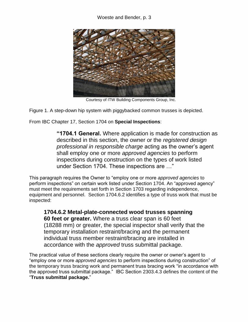
For the benefit and convenience of the reader, pertinent sections of the IBC with respect to design and inspection of 18 m (60 ft) and greater MPC wood trusses follow. Figure 1 gives an example of a complex roof system under construction
From IBC Chapter 23 on Wood, Section 2303.4 Trusses:
“2303.4.1.3 Trusses spanning 60 feet or greater. The owner shall contract with any qualified registered design professional for the design of the temporary installation restraint/bracing and the permanent individual truss member restraint/bracing for all trusses with clear spans 60 feet (18 288 mm) or greater.”
This section requires the Owner to
“contract with any qualified registered design professional”
for the design of the temporary and permanent truss bracing.
This section highlights the need for the Owner to allocate funding for the truss bracing designs at the contract stage of the project.
It should be noted that “any qualified registered professional” can assume the role of temporary and permanent bracing designer for the project. Realizing that wood trusses are typically designed by a truss engineer and approved by the registered design professional of record (Building Designer) after the contract phase of the project, the use of the word “any” allows for the Owner (or owner’s agent) flexibility to engage a RDP with expertise in wood truss bracing design and inspection. Modern long-span roof truss systems can be complicated as illustrated in Figure 1.
Woeste and Bender, p. 3
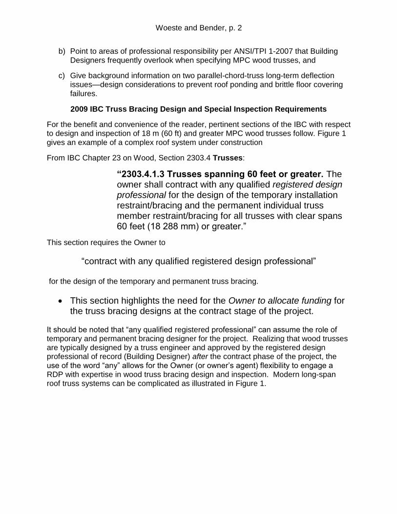
Courtesy of ITW Building Components Group, Inc.
Figure 1. A step-down hip system with piggybacked common trusses is depicted. From IBC Chapter 17, Section 1704 on Special Inspections:
“1704.1 General. Where application is made for construction as described in this section, the owner or the registered design professional in responsible charge acting as the owner’s agent shall employ one or more approved agencies to perform inspections during construction on the types of work listed under Section 1704. These inspections are …”
This paragraph requires the Owner to “employ one or more approved agencies to perform inspections” on certain work listed under Section 1704. An “approved agency” must meet the requirements set forth in Section 1703 regarding independence, equipment and personnel. Section 1704.6.2 identifies a type of truss work that must be inspected:
1704.6.2 Metal-plate-connected wood trusses spanning 60 feet or greater. Where a truss clear span is 60 feet (18288 mm) or greater, the special inspector shall verify that the temporary installation restraint/bracing and the permanent individual truss member restraint/bracing are installed in accordance with the approved truss submittal package.
The practical value of these sections clearly require the owner or owner’s agent to “employ one or more approved agencies to perform inspections during construction” of the temporary truss bracing work and permanent truss bracing work “in accordance with the approved truss submittal package.” IBC Section 2303.4.3 defines the content of the “Truss submittal package.”
Woeste and Bender, p. 4
It is not precisely clear how the new requirements for the design and inspection of wood truss bracing will be approached or managed by the local building code departments. Referring to the last sentence in IBC Section 107.3.4.1:
“107.3.4.1 General. …. The registered design professional in responsible charge shall be responsible for reviewing and coordinating submittal documents prepared by others, including phased and deferred submittal items, for compatibility with the design of the building.”
The temporary and permanent bracing designs per IBC, Section 2303.4.1.3 could logically be submitted as part of the Truss Submittal Package (IBC, Section 2303.4.3). Regardless of when the temporary and permanent bracing designs are submitted to the authority having jurisdiction (AHJ), the original construction documents submitted to the AHJ should include a list of the deferred submittals that specifically includes temporary and permanent bracing designs for the project. The responsibility and process for deferred submittals are defined by the second paragraph of IBC Section 107.3.4.2:
107.3.4.2 “Deferral of any submittal items shall have the prior approval of the building official. The registered design professional in responsible charge shall list the deferred submittals on the construction documents for review by the building official.”
In summary, the 2009 IBC defines new requirements for the design and inspection of both temporary and permanent MPC wood truss bracing. It should be noted that the language in ANSI/TPI 1-2007 on wood truss bracing responsibilities for the application of long-span trusses is consistent with the 2009 IBC requirements.
Specifying MPC Wood Trusses per ANSI/TPI 1-2007
While some responsibilities defined by the new ANSI/TPI 1-2007 standard overlap responsibilities defined by previous editions of ANSI/TPI 1 (1995 and 2002), the new Chapter 2 Standard Responsibilities in the Design and Application of MPC Wood Trusses addresses additional issues and information valuable to all parties involved in MPC wood truss construction. The purpose of this section of this paper is to highlight areas of professional responsibility in Chapter 2 that Building Designers frequently overlook when MPC wood trusses are specified for a project and to emphasize a couple of parallel-chord-truss design requirements new to ANSI/TPI 1-2007. The discussion presented should be viewed only as a starting point for learning the responsibilities of the Building Designer when utilizing MPC wood trusses—all RDP’s are strongly encouraged to obtain a copy of ANSI/TPI 1-2007 for study and familiarity of the complete standard. Copies are available from the TPI3.
Woeste and Bender, p. 5
Building Designer Defined
ANSI/TPI 1-2007, Section 2.2, defines the Building Designer with respect to the application of MPC wood trusses:
“Building Designer: Owner of the Building or the Person that Contracts with the Owner for the design of the Framing Structural System and/or who is responsible for the preparation of the Construction Documents. When mandated by the Legal Requirements, the Building Designer shall be a Registered Design Professional.”
Building Designer Responsibilities
For the purpose of discussion, we will assume that the Building Designer (BD) is legally required to be a Registered Design Professional (RDP), hereafter referred to as the BD/RDP.
Sections 2.3.2 define the responsibilities of the BD/RDP engaged by the Owner:
“2.3.2 Requirements of the Registered Design Professional.
2.3.2.1 Construction Documents.
The Construction Documents shall be prepared by the Registered Design Professional for the Building and shall be of sufficient clarity to indicate the location, nature and extent of the work proposed, and show in detail that such documents conform to the Legal Requirements, including the Building Code.
2.3.2.2 Deferred Submittals.
The Registered Design Professional for the Building shall list the Deferred Submittals on the Construction Documents. The Registered Design Professional shall review Deferred Submittals in accordance with Section 2.3.2.3.
2.3.2.3 Review Submittal Packages.
The Registered Design Professional for the Building shall review the Truss Submittal Package for compatibility with the Building design. All such submittals shall include a notation indicating that they have been reviewed and whether or not they have been found to be in general conformance with the design of the Building.
2.3.2.4 Required Information in the Construction Documents.
The Registered Design Professional for the Building, through the Construction Documents, shall provide information sufficiently accurate and reliable to be used for facilitating the supply of the Structural Elements and other information for developing the design of the Trusses for the Building, and shall provide the following:
Woeste and Bender, p. 6
(a) All Truss and Structural Element orientations and locations.
(b) Information to fully determine all Truss profiles.
(c) All Structural Element and Truss support locations and bearing conditions (including the allowable bearing stress).
(d) The location, direction, and magnitude of all dead, live, and lateral loads applicable to each Truss including, but not limited to, loads attributable to: roof, floor, partition, mechanical, fire sprinkler, attic storage, rain and ponding, wind, snow (including snow drift and unbalanced snow), seismic; and any other loads on the Truss;
(e) All anchorage designs required to resist uplift, gravity, and lateral loads.
(f) Truss-to-Structural Element connections, but not Truss-to-Truss connections.
(g) Permanent Building Stability Bracing; including Truss anchorage connections to the Permanent Building Stability Bracing.
(h) Criteria related to serviceability issues including:
(1) Allowable vertical, horizontal or other required deflection criteria. (2) Any dead load, live load, and in-service creep deflection criteria for flat
roofs subject to ponding loads. (3) Any Truss camber requirements. (4) Any differential deflection criteria from Truss-to-Truss or Truss-to-adjacent
Structural Element. (5) Any deflection and vibration criteria for floor Trusses including:
(a) Any strongback bridging requirements. (b) Any dead load, live load, and in-service creep deflection criteria for
floor Trusses supporting stone or ceramic tile finishes. (6) Moisture, temperature, corrosive chemicals and gases expected to result
in: (a) Wood moisture content exceeding 19 percent,
(b) Sustained temperatures exceeding 150 degrees F, and/or (c) Corrosion potential from wood preservatives or other sources that may
be detrimental to Trusses.” The requirements in Section 2.3.2.4, (a) through (h) on “Required Information in the Construction Documents”, are frequently not completed by some BD/RDPs. In a nutshell, specifications by the BD/RDP related to the design of the Trusses for the Building must be communicated to the Truss Designer through the Construction Documents. The Truss Designer relies on information set forth in the Construction Documents to execute the individual truss designs based on the provisions of
ANSI/TPI 1 (See ANSI/TPI 1-2007, Sections 2.3.5.1 and 2.3.5.2).
Woeste and Bender, p. 7
Specifications Related to Creep Deflection
All elements listed in Section 2.3.2.4 are important for the BD/RDP to consider and make specifications that are warranted for a specific building. Some specifiers may not have the requisite background to make informed specifications in regard to the long-term “creep deflection” behavior of parallel-chord wood trusses. In the next two sections, we discuss the role of creep deflection as it may impact the possibility of “flat roof ponding” or a failure of brittle surfaces on floor trusses (e.g. ceramic tile).
Specifying a Creep Factor for Flat Roofs
Regarding 2.3.2.4, (h) Criteria related to serviceability issues, Subsection (2), addresses dead and live loads and associated “creep deflection” for flat roofs subject to ponding action. Probably the most common flat roof design specification is a roof slope of 1:48. Creep deflection behavior of wood beams and wood truss components is difficult to predict. ANSI/TPI 1-2007 Section 7.6.1 requires time dependent or creep deflection to be included in the total deflection calculation for MPC trusses. The deflection equation in Section 7.6.1 has the following form:
Total Load Deflection = Kcr * Sustained Load Deflection + Short-Term Load Deflection
The minimum creep factors given, 1.5 for dry lumber and 2.0 for green or wet service conditions, match the equation for solid-sawn lumber in the ANSI/AF&PA NDS-20054 and may not be adequate for a flat roof (such as a 1:48 slope) wood truss. The first step in evaluating the protection afforded by the total deflection equation in ANSI/TPI 1-2007 is to realize that some snow loads in northern climates and other roof loads can be “sustained” even though they are not technically a “dead load.” A HVAC unit is “fixed” to the structure and it is clearly a “sustained” load that should be multiplied by the creep factor, Kcr, when the affected trusses are checked for total load deflection. For the case of parallel-chord roof trusses with a potential for ponding action, the BD/RDP should detail and make specifications to ensure that HVAC unit loads resting on a couple of trusses are specified for all stress analyses of the affected trusses and to ensure that the HVAC loads and other sustained loads are included in the total load deflection check using an appropriate Kcr;; i.e. specify that HVAC loads are dead loads and verify them on Truss Design Drawings (TDD) during review. The ANSI/TPI 1-2007 Commentary & Appendices5 provides discussion and recommendations on the creep deflection issue. After some discussion of research on the subject, the ANSI/TPI 1-2007 Commentary recommends a minimum creep factor adjustment for a total dead load of 1.2 kPa (25 psf) or greater:
“For floor truss applications with a total dead load of 25 psf or greater where the Registered Design Professional for the Building or the Building Designer does not specify adjustment factors for serviceability issues (per Sections
Woeste and Bender, p. 8
2.3.2.4(h)(5) or Section 2.4.2.4(h)(5), respectively), a creep factor, Kcr, of 2.0 is recommended as a minimum adjustment in lieu of the 1.5 factor for seasoned lumber used in dry conditions.”
It should be noted that the use of 2.0 versus 1.5 is a recommendation only. The ANSI/TPI 1-2007 recommendation does not address the creep potential of sustained loads significantly above 1.2 kPa (25 psf). The authors have published one method for estimating a creep factor based on the results of long-term (10-yr.) testing of MPC floor trusses.6 The calculation method includes the ratio of “sustained load” to total design load which is known to be an important variable for predicting creep deflection of dimension lumber. The authors also discuss prescriptive measures that a BD/RDP may consider and specify for minimizing the likelihood of a flat roof ponding failure. Specifying a Creep Factor for Floors with Stone or Ceramic Tile Finishes When ceramic tile and grout failures occur 1-5 yrs after the time of construction on wood-joist framing systems, creep deflection appears to be a contributing factor. Subsection (5)(b) addresses design loads and creep deflection criteria for floor trusses supporting stone or ceramic tile finishes. With the increased customer preference for stone and ceramic tile, it is important that the BD communicates the dead and live design loads for the completed floor to the affected parties through the Construction Documents. For a typical residential carpeted or hardwood finish floor, designers often use a 40-10-0-5 psf (top chord live, top chord dead, bottom chord live, bottom chord dead) load specification. The “carpeted floor on wood subfloor” dead load specification (10 psf) may be woefully inadequate for some ceramic tile installation methods for wood truss (I-joist or solid-sawn joist) framing. To assess and specify an adequate top chord dead load for a ceramic tile installation, the BD/RDP must first determine which “installation method” will be used for the selected tile based on the floor truss spacing. The selected installation method impacts total design dead load. This step may require coordination with the Tile Contractor. Tile industry installation methods are contained in the 2011 TCNA Handbook for Ceramic Tile Installation.7 The new TCNA handbook lists typical weights of each installation method. The weight of the tile installation method must be added to the dead load of the specific floor construction and other dead loads (such as a kitchen island with granite top) to obtain the total dead load(s) for the area.
The impact of creep deflection on ceramic tile installation performance should be considered by the BD/RDP when specifying floor trusses. Some floor live loads can also be “sustained.” For example, a large piano rested primarily on two floor trusses is technically a “live load”, however, with respect to creep deflection it most likely acts as a “sustained load.” The ratio of all sustained loads to total floor load is an important variable for assessing the potential role of creep deflection on in-service performance of stone or tile installations. The potential for a creep induced failure of stone or ceramic tile on wood floor trusses can be minimized by specifying a creep factor based on the results of long-term tests of MPC floor trusses subjected to a sustained loading.6
Woeste and Bender, p. 9
Conclusions ANSI/TPI 1-2007 is the 2009 IBC referenced standard for MPC wood trusses. With the implementation of the new 2009 IBC requirements for installing wood trusses with spans 18 m (60 ft) and greater, the number of accidents should greatly be reduced—a benefit to Owners, RDPs, General Contractors, Truss Erection Subcontractors, and the construction workers involved in the process of wood truss installation.
The safe installation of long span trusses requires professional engineering knowledge of the structural behavior of MPC wood trusses and commensurate design and inspection experience related to the sequential process of handling and temporary bracing of a roof truss system.
Without the aforementioned knowledge and experience, it is unsafe to attempt long span truss installation.
The new code requirement for the Owner to engage a qualified registered design professional for the purpose of design and inspection of the temporary truss bracing was the missing component needed to consistently ensure the safe erection of long-span MPC wood trusses.
Prior to the 2009 IBC, the BD/RDP for a project was responsible for the permanent truss bracing design without a code requirement for inspection of the installation. With the new requirement for the BD/RDP to inspect the permanent truss bracing, permanent bracing related failures should be greatly reduced as a primary cause of snow load induced roof failures.
BD/RDPs frequently overlook areas of professional responsibility per ANSI/TPI 1-2007 when specifying MPC wood trusses.
The BD/RDP should carefully review Chapter 2 of ANSI/TPI 1-2007 early in the design phase of a project because broad design aspects of a project can be affected by seemingly unrelated truss design issues.
For example, the specification of a flat roof structure verses a pitched roof can require additional specifications well beyond just the design slope of the top chord and all required loads per the applicable building code.
Woeste and Bender, p. 10
Notes 1 See Truss Plate Institute. 2008. ANSI/TPI 1-2007 National design standard for metal
plate connected wood truss construction. Truss Plate Institute, 218 North Lee Street, Ste 312, Alexandria, VA 22314.
2 Visit http://www.sbcindustry.com/bcsi.php
3 Visit www.tpinst.org/publication-tpi1.html#TPI12007 4 See American Forest and Paper Association. 2005. ANSI/AF&PA NDS-2005 National
design specification for wood construction ASD/LRFD. American Forest & Paper Association, Washington, D.C.
5 Visit www.tpinst.org/TPI1-2007_Commentary-Appendices_web.pdf
6 See Bender, D. A. and F. E. Woeste. 2011. Creep deflection in design of metal plate connected wood trusses. ASCE Practice Periodical on Structural Design and Construction, Vol. 16, No. 1, February.
7 Visit http://www.tileusa.com/publication_main.htm
32 Structural Engineer February 2012 www.gostructural.com
Once state codes or local jurisdictions adopt the 2009 International Building Code (IBC), owners of a project with metal-plate-connected (MPC) wood trusses will be required to engage a registered professional to design and inspect both temporary and permanent bracing for such trusses when spanning 60 feet (18 meters) and greater. What does this mean for designers of these schools, places of worship, and retail projects?
The owner’s responsibility for engaging a design professional for these purposes is also defined by American National Standards Institute/Truss Plate Institute (ANSI/TPI) 1-2007, National Design Standard for Metal Plate Connected Wood Truss Construction, which is the 2009 IBC-referenced standard for MPC wood trusses.
Before the 2009 IBC, the code did not require a registered design professional (RDP) to be responsible for the temporary bracing or the inspection of the permanent bracing. These items were usually left up to the general contractor (or truss erection subcontractor). Truss industry safety literature recognized the professional expertise needed to safely erect long-span wood trusses by making the recommendation: Consult a professional engineer for trusses longer than 60 feet (from Building Component Safety Information (BCSI) 2008, Guide to Good Practice for Handling, Installing, Restraining, and Bracing of Metal Plate Connected Wood Trusses).
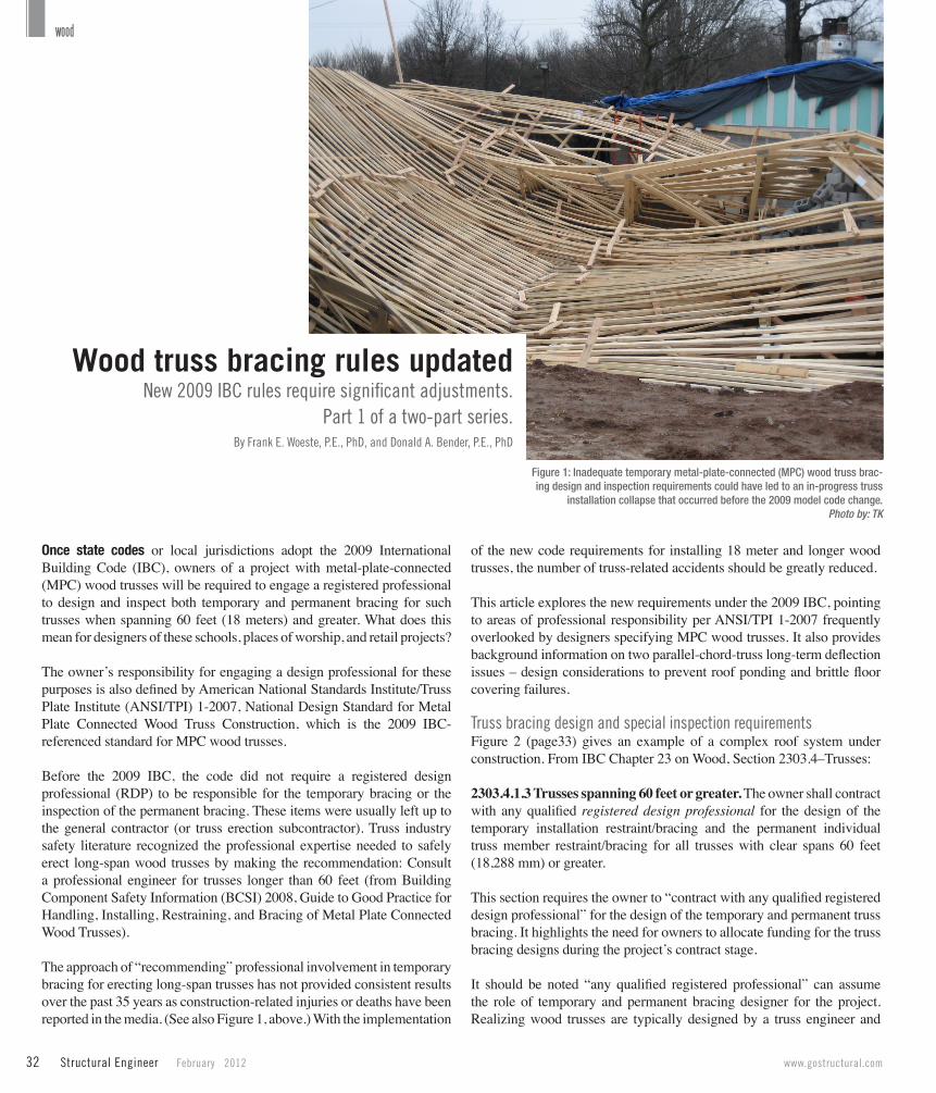
The approach of “recommending” professional involvement in temporary bracing for erecting long-span trusses has not provided consistent results over the past 35 years as construction-related injuries or deaths have been reported in the media. (See also Figure 1, above.) With the implementation
of the new code requirements for installing 18 meter and longer wood trusses, the number of truss-related accidents should be greatly reduced.
This article explores the new requirements under the 2009 IBC, pointing to areas of professional responsibility per ANSI/TPI 1-2007 frequently overlooked by designers specifying MPC wood trusses. It also provides background information on two parallel-chord-truss long-term deflection issues – design considerations to prevent roof ponding and brittle floor covering failures.
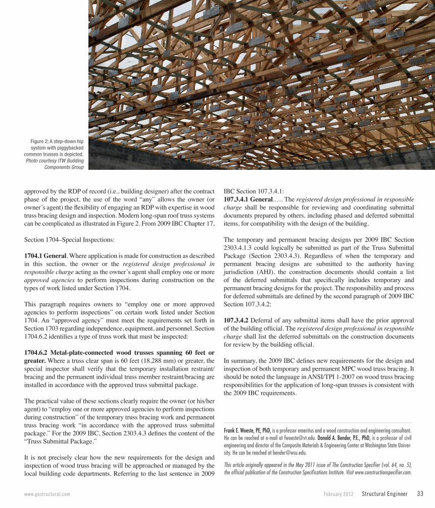
Truss bracing design and special inspection requirementsFigure 2 (page33) gives an example of a complex roof system under construction. From IBC Chapter 23 on Wood, Section 2303.4–Trusses:
2303.4.1.3 Trusses spanning 60 feet or greater. The owner shall contract with any qualified registered design professional for the design of the temporary installation restraint/bracing and the permanent individual truss member restraint/bracing for all trusses with clear spans 60 feet (18,288 mm) or greater.
This section requires the owner to “contract with any qualified registered design professional” for the design of the temporary and permanent truss bracing. It highlights the need for owners to allocate funding for the truss bracing designs during the project’s contract stage.
It should be noted “any qualified registered professional” can assume the role of temporary and permanent bracing designer for the project. Realizing wood trusses are typically designed by a truss engineer and
wood
Wood truss bracing rules updatedNew 2009 IBC rules require significant adjustments.
Part 1 of a two-part series.By Frank E. Woeste, P.E., PhD, and Donald A. Bender, P.E., PhD
Figure 1: Inadequate temporary metal-plate-connected (MPC) wood truss brac-ing design and inspection requirements could have led to an in-progress truss
installation collapse that occurred before the 2009 model code change.Photo by: TK
www.gostructural.com February 2012 Structural Engineer 33
approved by the RDP of record (i.e., building designer) after the contract phase of the project, the use of the word “any” allows the owner (or owner’s agent) the flexibility of engaging an RDP with expertise in wood truss bracing design and inspection. Modern long-span roof truss systems can be complicated as illustrated in Figure 2. From 2009 IBC Chapter 17,
Section 1704–Special Inspections:
1704.1 General. Where application is made for construction as described in this section, the owner or the registered design professional in responsible charge acting as the owner’s agent shall employ one or more approved agencies to perform inspections during construction on the types of work listed under Section 1704.
This paragraph requires owners to “employ one or more approved agencies to perform inspections” on certain work listed under Section 1704. An “approved agency” must meet the requirements set forth in Section 1703 regarding independence, equipment, and personnel. Section 1704.6.2 identifies a type of truss work that must be inspected:
1704.6.2 Metal-plate-connected wood trusses spanning 60 feet or greater. Where a truss clear span is 60 feet (18,288 mm) or greater, the special inspector shall verify that the temporary installation restraint/bracing and the permanent individual truss member restraint/bracing are installed in accordance with the approved truss submittal package.
The practical value of these sections clearly require the owner (or his/her agent) to “employ one or more approved agencies to perform inspections during construction” of the temporary truss bracing work and permanent truss bracing work “in accordance with the approved truss submittal package.” For the 2009 IBC, Section 2303.4.3 defines the content of the “Truss Submittal Package.”
It is not precisely clear how the new requirements for the design and inspection of wood truss bracing will be approached or managed by the local building code departments. Referring to the last sentence in 2009
IBC Section 107.3.4.1:107.3.4.1 General.…. The registered design professional in responsible charge shall be responsible for reviewing and coordinating submittal documents prepared by others, including phased and deferred submittal items, for compatibility with the design of the building.
The temporary and permanent bracing designs per 2009 IBC Section 2303.4.1.3 could logically be submitted as part of the Truss Submittal Package (Section 2303.4.3). Regardless of when the temporary and permanent bracing designs are submitted to the authority having jurisdiction (AHJ), the construction documents should contain a list of the deferred submittals that specifically includes temporary and permanent bracing designs for the project. The responsibility and process for deferred submittals are defined by the second paragraph of 2009 IBC Section 107.3.4.2:
107.3.4.2 Deferral of any submittal items shall have the prior approval of the building official. The registered design professional in responsible charge shall list the deferred submittals on the construction documents for review by the building official.
In summary, the 2009 IBC defines new requirements for the design and inspection of both temporary and permanent MPC wood truss bracing. It should be noted the language in ANSI/TPI 1-2007 on wood truss bracing responsibilities for the application of long-span trusses is consistent with the 2009 IBC requirements.
Frank E. Woeste, PE, PhD, is a professor emeritus and a wood construction and engineering consultant. He can be reached at e-mail at [email protected]. Donald A. Bender, P.E., PhD, is a professor of civil engineering and director of the Composite Materials & Engineering Center at Washington State Univer-sity. He can be reached at [email protected].
Figure 2: A step-down hip system with piggybacked
common trusses is depicted.Photo courtesy ITW Building
Components Group
This article originally appeared in the May 2011 issue of The Construction Specifier (vol. 64, no. 5), the official publication of the Construction Specifications Institute. Visit www.constructionspecifier.com.