Embed Size (px)
Citation preview
BUILD 125 August/September 2011 17
DESIGN RIGHT
DECK BRACING DESIGNThe BRANZ Helpline is frequently asked how to work out bracing requirements for decks. Here, we work through the
process step by step.By Alide Elkink, Freelance Technical Writer, Wellington
NZS 3604:2011 Timber-framed buildings section 7.4 is the non-specific design standard for timber decks that are supported from the main part of a building and are no more than 3.0 m high from the lowest point of cleared ground to the upper surface
of the finished deck. Specific engineering design is required for decks over this height.
Bracing needed if over 2 m from building
Paragraph 7.4.2.1 states that no bracing is required when a deck projects less than 2.0 m from the building and is attached to the building on one or more sides. The bracing provided by the building will satisfy the bracing requirements for the deck.
Decks that project more than 2.0 m from the building must have subfloor bracing (anchor, braced or cantilevered piles) at half the bracing demand required by Table 5.8 for light/light/light cladding, 0° roof slope and subfloor structure (paragraph 7.4.2.2). Decks do not have to be braced for wind. WORK IT OUTReferring to Table 5.8 for light/light/light cladding, 0° roof slope and subfloor structure (circled in Figure 1) and halving this:
15 × 0.5 = 7.5 bracing units per square metre (BU/m²). The bottom section of Table 5.8 gives the multiplication factor for
the appropriate earthquake zone and subsoil classification (paragraph 5.3.1). If no soil classification is available for the site, use soil class E to obtain the multiplication factor.
To work out the bracing demand for a 20 m² deck (say, 5 m wide and projecting 4 m from the building) in earthquake (EQ) zone 3, multiply the bracing units per square metre (7.5) by the multiplication factor from Table 5.8 (1.0) and the area of the deck (20):
7.5 BU/m² × 1.0 × 20 m² = 150 BU.So the bracing demand for our 20 m² deck is 150 bracing units (see
Figure 2).
Distributing bracing units
Next, the bracing units need to be distributed over the deck area. NZS 3604:2011 section 5.5 says: ❚ bracing lines must be at no more than 5.0 m spacings ❚ bracing units must, as far as possible, be evenly distributed along lines of bracing.
Bracing lines in perimeter foundation and subfloor framing, or internal lines parallel to these (paragraph 5.5.2.1), require not less than the greater of: ❚ 100 BUs
Figure 1: Part of Table 5.8 from NZS 3604:2011 Timber-framed buildings is used to work out deck bracing demand. © Standards New Zealand 2011. Reproduced with permission.
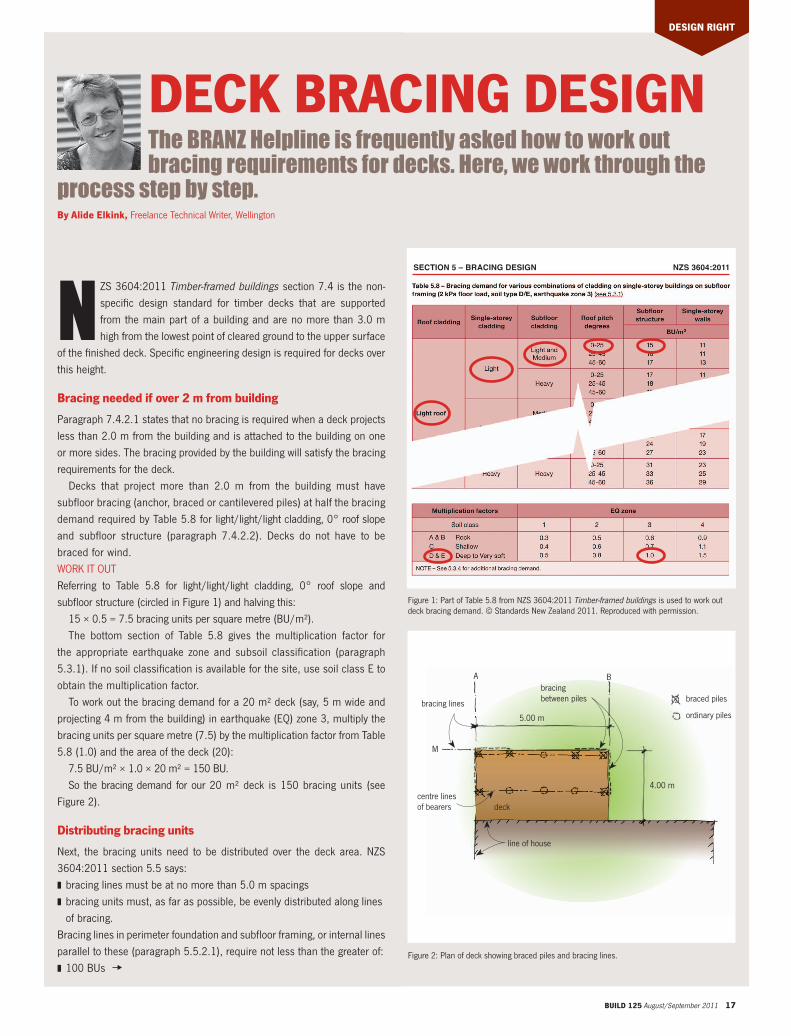
centre lines of bearers
Figure 2: Plan of deck showing braced piles and bracing lines.
line of house
ordinary piles
braced piles
deck
bracing between pilesbracing lines
5.00 m
4.00 m
M
A B
SECTION 5 – BRACING DESIGN NZS 3604:2011
18 BUILD 125 August/September 2011
❚ 50% of the total bracing demand divided by the number of bracing lines in the direction being considered (along or across).
External subfloor bracing lines (paragraph 5.5.2.2) require not less than the greater of the two above from paragraph 5.5.2.1 or: ❚ 15 BUs multiplied by the length in metres of the external wall.
Work it out
In our example, because the bracing lines do not exceed 5 m spacing, bracing is required along external lines only.WHAT BRACING DEMAND IS REQUIRED?For line A (external line): 50% of the total bracing demand (150/2 = 75) divided by the number of bracing lines (75/2 = 37.5) equals 38 BUs; and 15 × 4 m equals 60 BUs, less than 100 BUs. So line A requires 100 BUs minimum.
For line B (internal line): 50% of the total bracing demand (150/2 = 75) divided by the number of bracing lines (75/2 = 37.5) equals 38 BUs, less than 100 BUs. So line B require 100 BUs minimum.
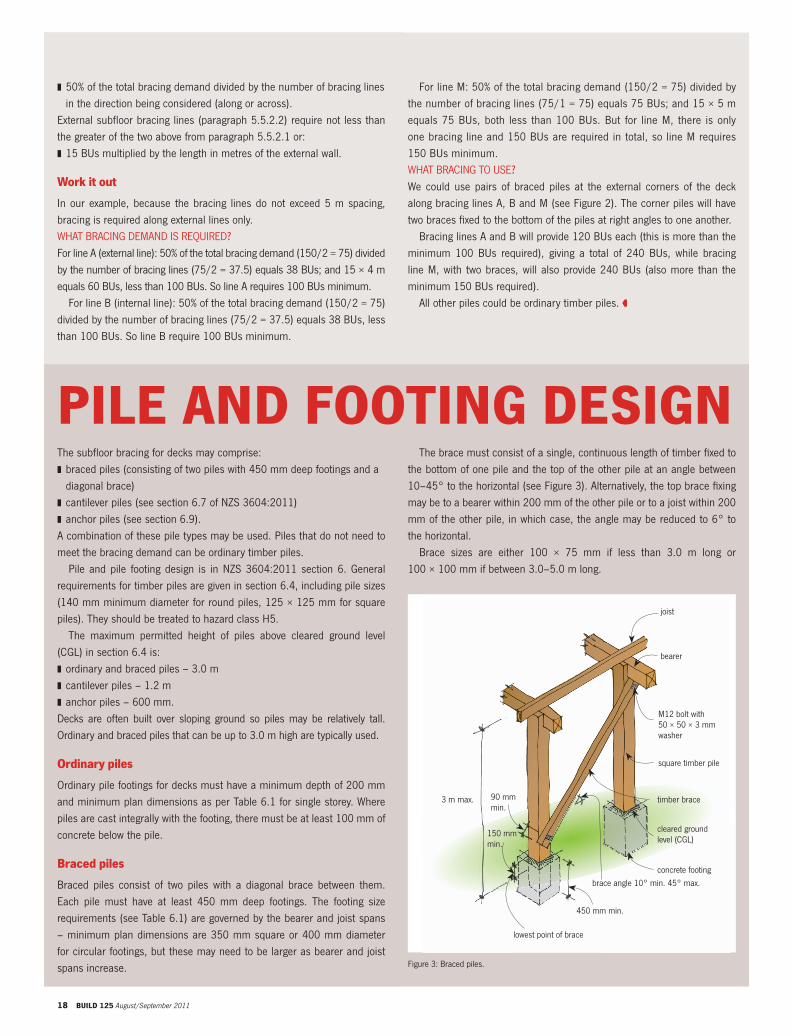
Figure 3: Braced piles.
joist
bearer
M12 bolt with 50 × 50 × 3 mm washer
square timber pile
lowest point of brace
brace angle 10° min. 45° max.
timber brace
cleared ground level (CGL)
concrete footing
90 mm min.
3 m max.
450 mm min.
150 mm min.
The subfloor bracing for decks may comprise: ❚ braced piles (consisting of two piles with 450 mm deep footings and a diagonal brace)
❚ cantilever piles (see section 6.7 of NZS 3604:2011) ❚ anchor piles (see section 6.9).
A combination of these pile types may be used. Piles that do not need to meet the bracing demand can be ordinary timber piles.
Pile and pile footing design is in NZS 3604:2011 section 6. General requirements for timber piles are given in section 6.4, including pile sizes (140 mm minimum diameter for round piles, 125 × 125 mm for square piles). They should be treated to hazard class H5.
The maximum permitted height of piles above cleared ground level (CGL) in section 6.4 is: ❚ ordinary and braced piles – 3.0 m ❚ cantilever piles – 1.2 m ❚ anchor piles – 600 mm.
Decks are often built over sloping ground so piles may be relatively tall. Ordinary and braced piles that can be up to 3.0 m high are typically used.
Ordinary piles
Ordinary pile footings for decks must have a minimum depth of 200 mm and minimum plan dimensions as per Table 6.1 for single storey. Where piles are cast integrally with the footing, there must be at least 100 mm of concrete below the pile.
Braced piles
Braced piles consist of two piles with a diagonal brace between them. Each pile must have at least 450 mm deep footings. The footing size requirements (see Table 6.1) are governed by the bearer and joist spans – minimum plan dimensions are 350 mm square or 400 mm diameter for circular footings, but these may need to be larger as bearer and joist spans increase.
PILE AND FOOTING DESIGN
For line M: 50% of the total bracing demand (150/2 = 75) divided by the number of bracing lines (75/1 = 75) equals 75 BUs; and 15 × 5 m equals 75 BUs, both less than 100 BUs. But for line M, there is only one bracing line and 150 BUs are required in total, so line M requires 150 BUs minimum.WHAT BRACING TO USE?We could use pairs of braced piles at the external corners of the deck along bracing lines A, B and M (see Figure 2). The corner piles will have two braces fixed to the bottom of the piles at right angles to one another.
Bracing lines A and B will provide 120 BUs each (this is more than the minimum 100 BUs required), giving a total of 240 BUs, while bracing line M, with two braces, will also provide 240 BUs (also more than the minimum 150 BUs required).
All other piles could be ordinary timber piles.
The brace must consist of a single, continuous length of timber fixed to the bottom of one pile and the top of the other pile at an angle between 10–45° to the horizontal (see Figure 3). Alternatively, the top brace fixing may be to a bearer within 200 mm of the other pile or to a joist within 200 mm of the other pile, in which case, the angle may be reduced to 6° to the horizontal.
Brace sizes are either 100 × 75 mm if less than 3.0 m long or 100 × 100 mm if between 3.0–5.0 m long.
BUILD 125 August/September 2011 19
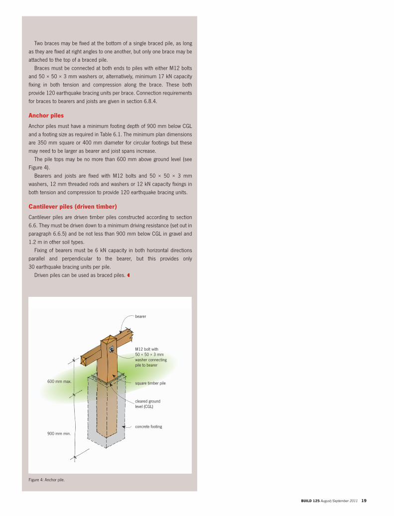
Figure 4: Anchor pile.
bearer
M12 bolt with 50 × 50 × 3 mm washer connecting pile to bearer
square timber pile
cleared ground level (CGL)
concrete footing
900 mm min.
600 mm max.
Two braces may be fixed at the bottom of a single braced pile, as long as they are fixed at right angles to one another, but only one brace may be attached to the top of a braced pile.
Braces must be connected at both ends to piles with either M12 bolts and 50 × 50 × 3 mm washers or, alternatively, minimum 17 kN capacity fixing in both tension and compression along the brace. These both provide 120 earthquake bracing units per brace. Connection requirements for braces to bearers and joists are given in section 6.8.4.
Anchor piles
Anchor piles must have a minimum footing depth of 900 mm below CGL and a footing size as required in Table 6.1. The minimum plan dimensions are 350 mm square or 400 mm diameter for circular footings but these may need to be larger as bearer and joist spans increase.
The pile tops may be no more than 600 mm above ground level (see Figure 4).
Bearers and joists are fixed with M12 bolts and 50 × 50 × 3 mm washers, 12 mm threaded rods and washers or 12 kN capacity fixings in both tension and compression to provide 120 earthquake bracing units.
Cantilever piles (driven timber)
Cantilever piles are driven timber piles constructed according to section 6.6. They must be driven down to a minimum driving resistance (set out in paragraph 6.6.5) and be not less than 900 mm below CGL in gravel and 1.2 m in other soil types.
Fixing of bearers must be 6 kN capacity in both horizontal directions parallel and perpendicular to the bearer, but this provides only 30 earthquake bracing units per pile.
Driven piles can be used as braced piles.