Embed Size (px)
Citation preview
8720MC Regenerative Power Supply
Installation Manual

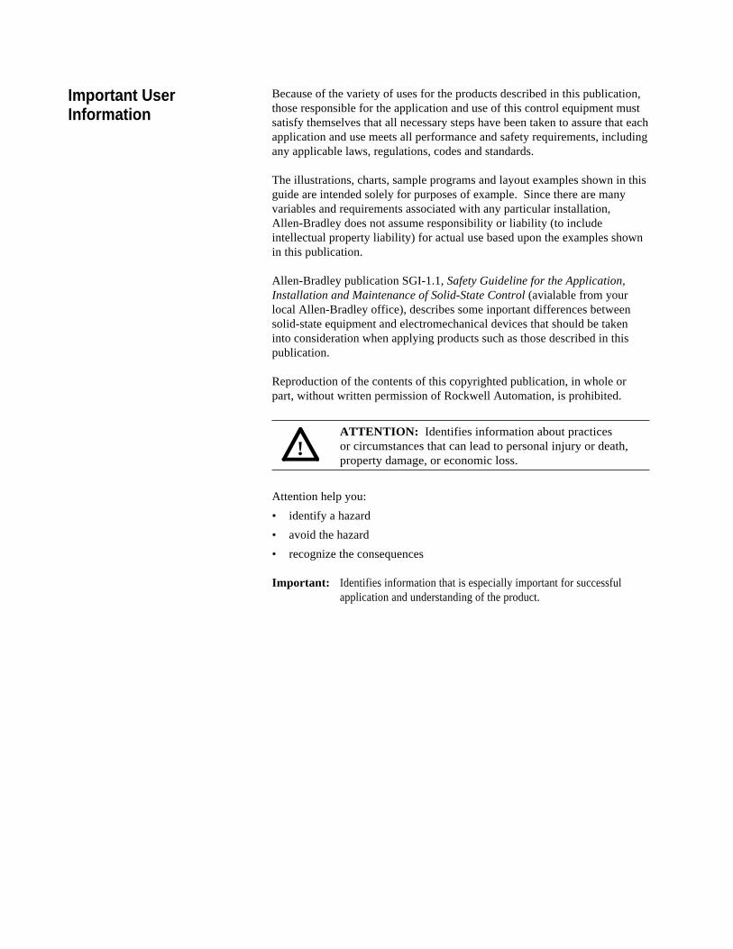
Because of the variety of uses for the products described in this publication,those responsible for the application and use of this control equipment mustsatisfy themselves that all necessary steps have been taken to assure that eachapplication and use meets all performance and safety requirements, includingany applicable laws, regulations, codes and standards.
The illustrations, charts, sample programs and layout examples shown in thisguide are intended solely for purposes of example. Since there are manyvariables and requirements associated with any particular installation,Allen-Bradley does not assume responsibility or liability (to includeintellectual property liability) for actual use based upon the examples shownin this publication.
Allen-Bradley publication SGI-1.1, Safety Guideline for the Application,Installation and Maintenance of Solid-State Control (avialable from yourlocal Allen-Bradley office), describes some inportant differences betweensolid-state equipment and electromechanical devices that should be takeninto consideration when applying products such as those described in thispublication.
Reproduction of the contents of this copyrighted publication, in whole orpart, without written permission of Rockwell Automation, is prohibited.
ATTENTION: Identifies information about practicesor circumstances that can lead to personal injury or death,property damage, or economic loss.
Attention help you:
• identify a hazard
• avoid the hazard
• recognize the consequences
Important: Identifies information that is especially important for successfulapplication and understanding of the product.
!
Important UserInformation

If this product has the CE mark it is approved for installation within theEuropean Union and EEA regions. It has been designed and tested to meetthe following directives.
EMC Directive
This product is tested to meet the Council Directive 89/336/ECElectromagnetic Compatibility (EMC) by applying the following standards,in whole or in part, documented in a technical construction file:
• EN 50081-2 EMC - Generic Emission Standard, Part 2 -Industrial Environment
• EN 50082-2-EMC - Generic Immunity Standard, Part 2 -Industrial Environment
This product is intended for use in an industrial environment.
Low Voltage Directive
This product is tested to meet Council Directive 73/23/EEC Low Voltage, byapplying the safety requirements of EN 61131-2 Programmable Controllers,Part 2 - Equipment Requirements and Tests. For specific informationrequired by EN 61131-2, see the appropriate sections in this publication, aswell as the Allen-Bradley pulbication Industrial Automation Wiring andGrounding Guidelines For Noise Immunity, publication 1770-4.1.
This equipment is classified as open equipment and must be mounted in anenclosure during operation to provide safety protection.
European Communities(EC) DirectiveCompliance
Chapter 1Introduction .................................................................................. 1-1Finding Information ...................................................................... 1-1Assumptions About the Audience ................................................ 1-2Notes on Handling the 8720MC-RPS Regenerative PowerSupply .......................................................................................... 1-3
Chapter 2Model Numbers of the 8720MC-RPS Regenerative PowerSupply and its Accessories .......................................................... 2-1Power Rating ................................................................................ 2-2Appearance of the 8720MC-RPS Regenerative Power Supply .. 2-2
Appearance of Model 8720MC-RPS027 and8720MC-RPS065 ................................................................... 2-2Appearance of Model 8720MC-RPS190................................ 2-4
Main Components and Locations ................................................ 2-5Terminal Blocks on the Main Circuit ............................................ 2-10
Main Power Terminal Block (TB1) for Model 8720MC-RPS027 and 8720MC-RPS065 .............................................. 2-12Control Power Terminal Block (TB2) for Model 8720MC-RPS027 and 8720MC-RPS065 .............................................. 2-12Mainl Power Terminal Bar for Model 8720MC-RPS190 ........ 2-13Control Power Terminal Block (TB2) and Control TerminalBlock (TB4) for Model 8720MC-RPS190 ............................... 2-13
Regulator Board ........................................................................... 2-14Jumpers and Switches ........................................................... 2-15Sequence Signal Terminal Block (TB3) ................................. 2-17
Chapter 3Installation Site ............................................................................. 3-1
Environmental Conditions to be Met ...................................... 3-1Required Total Area ............................................................... 3-2Recommended Air Flow Clearance ....................................... 3-7
Notes on Installation .................................................................... 3-7
Chapter 4Recommended Wire Sizes .......................................................... 4-1
Recommended Wire Sizes for Power Wiring to the MainPower Terminal Block (TB1) and the Main Power TerminalBars ........................................................................................ 4-2Recommended Wire Sizes for Power Wiring to the ControlPower Terminal Block (TB2) and the Control TerminalBlock (TB4) ............................................................................. 4-2
AC Input Power Wiring fot Model 8720MC-RPS027 and8720MC-RPS065 ......................................................................... 4-3
When Model 8720MC-RPS027 or 8720MC-RPS065 isoperated in the Power Regeneration Mode only ................... 4-7When Model 8720MC-RPS027 and 8720MC-RPS065 areadapted to Capacitors having large capacity ......................... 4-9Installing Circuit Breaker ........................................................ 4-11
Table of Contents
Contents of ThisManual
About 8720MC-RSPRegenerative PowerSupply
Installation
Wiring
Installing Main Magnetic Contactor ........................................ 4-11Installing Reactor .................................................................... 4-12Installing Varistor .................................................................... 4-13Installing Harmonic Filter ........................................................ 4-14Installing Input Fuses ............................................................. 4-14Installing Line Filters .............................................................. 4-14Bus Bar and Output Fuses ..................................................... 4-15
AC Input Power Wiring for Model 8720MC-RPS190 ................... 4-16When Model 8720MC-RPS190 is operated in the PowerRegeneration Mode only ........................................................ 4-22When Model 8720MC-RPS190 is adapted to Capacitorshaving large capacity ............................................................. 4-24Installing Circuit Breaker - 8720MCRPS190.......................... 4-26Installing ACL Unit (Reactor Assembly) - 8720MC-RPS190 .................................................................................. 4-26Installing Fuses - 8720MC-RPS190 ....................................... 4-27Installing 8720MC-EF190-VB EMC Filter Unit ....................... 4-28
Installing DC Bus Power Output Wiring - All RPS units .............. 4-29Grounding the 8720MC-RPS Regenerative Power Supply ......... 4-29Wiring To Comply with EMC ........................................................ 4-30Sequence Signal Wiring ............................................................... 4-32
Sequence Signal Wiring ......................................................... 4-32Operation Timing of Sequence Control Signals .................... 4-33
Installing Ribbon Cables .............................................................. 4-36Notes on Wiring ............................................................................ 4-37
Chapter 5Checking before Powering up the 8720MC-RPS RegenerativePower Supply .................................................................................. 5-1
Verifying the Installation ............................................................ 5-1Verifying the Rating of the 8720MC-RPS RegenerativePower Supply ............................................................................ 5-2Verifying Wiring ......................................................................... 5-2
Powering up the 8720MC-RPS Regenerative Power Supply ........ 5-2Operating the 8720MC-RPS Regenerative Power Supply ............. 5-3
Chapter 6Configuration of the Operation Panel ............................................. 6-1Operation Modes ............................................................................. 6-1
Monitor Mode ............................................................................. 6-2Program Mode ........................................................................... 6-3
Display ............................................................................................. 6-3Keypad ............................................................................................ 6-4Status LEDs .................................................................................... 6-5
Chapter 7Parameter Types ............................................................................. 7-1Protecting Parameters with Password ............................................ 7-3Displaying and Changing Parameter Values .................................. 7-3User Parameters ............................................................................. 7-3Factory Parameters ........................................................................ 7-5
ii Table of Contents
Start and Adjustment
Operation Panel
Parameters
Chapter 8Contents of Error Codes and Recovering ...................................... 8-2Accessing and Clearing the Entries in the Error Log ..................... 8-5Recovering from Fatal Error ........................................................... 8-6Warning Buzzer ............................................................................... 8-6
Chapter 9Safety Precautions .......................................................................... 9-1Preliminary Review ......................................................................... 9-2Troubleshooting Flow Charts .......................................................... 9-2
8720MC-RPS Regenerative Power Supply Does Not Run ...... 9-2DC Bus Voltage Does Not Go Up ............................................. 9-3
Chapter 10
Chapter 11Outline Drawings of the Reactors ................................................... 11-1Outline Drawing of the Varistors ..................................................... 11-3Outline Drawing of the Harmonic Filters ......................................... 11-4Outline Drawing of the Line Filters ................................................. 11-58720MC-EF190-VB EMC Filter Unit for Model 8720MC-RPS190BMand 8720MC-RPS190BS ................................................................ 11-7
Appendix A
Appendix B
Appendix C
Error Codes andWarning Buzzer
Inspecting Troubleand Recovering
Special ReplacementParts
Outline Drawings ofthe Peripheral Devices
Technical Specifications
Default Parameter Settings
Control Block Diagram
iiiTable of Contents

iv Table of Contents
End of Table of Contents
Chapter 1
Finding Information
Contents of This Manual
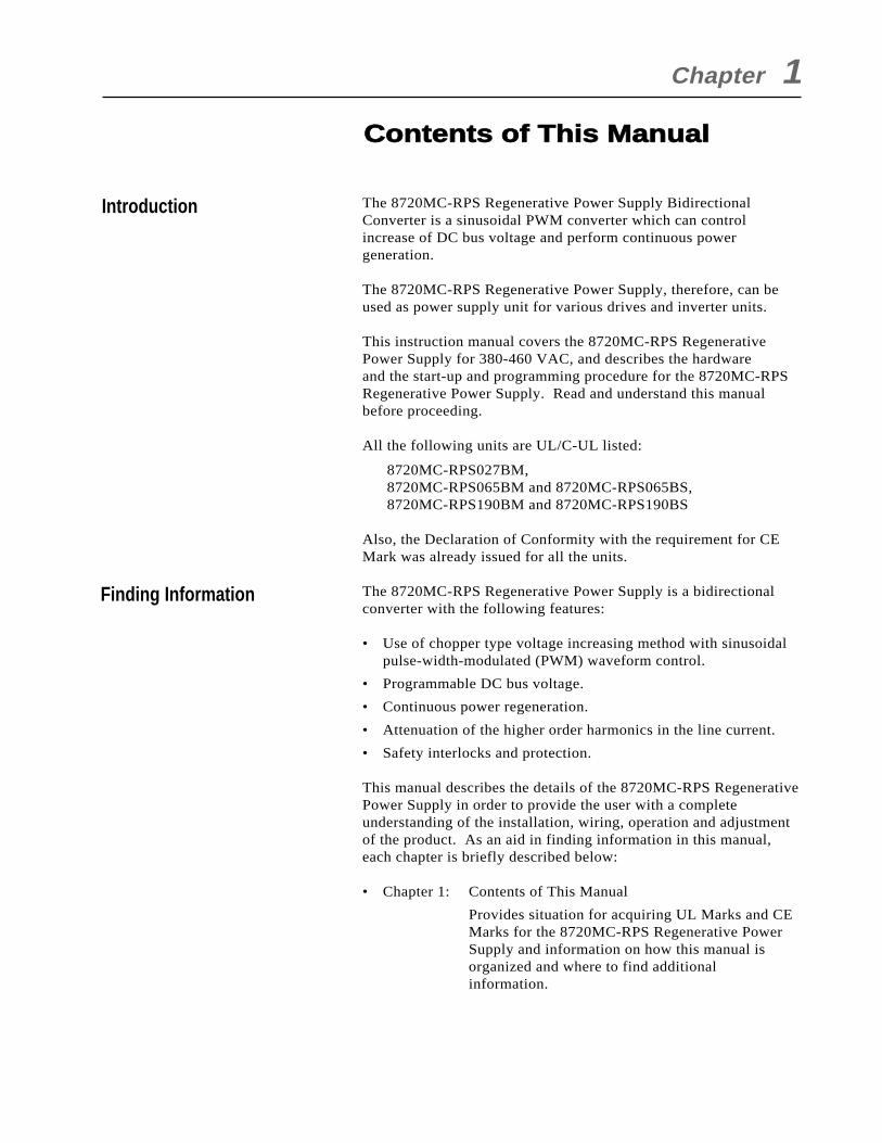
Introduction The 8720MC-RPS Regenerative Power Supply BidirectionalConverter is a sinusoidal PWM converter which can controlincrease of DC bus voltage and perform continuous powergeneration.
The 8720MC-RPS Regenerative Power Supply, therefore, can beused as power supply unit for various drives and inverter units.
This instruction manual covers the 8720MC-RPS RegenerativePower Supply for 380-460 VAC, and describes the hardwareand the start-up and programming procedure for the 8720MC-RPSRegenerative Power Supply. Read and understand this manualbefore proceeding.
All the following units are UL/C-UL listed:
8720MC-RPS027BM,8720MC-RPS065BM and 8720MC-RPS065BS,8720MC-RPS190BM and 8720MC-RPS190BS
Also, the Declaration of Conformity with the requirement for CEMark was already issued for all the units.
The 8720MC-RPS Regenerative Power Supply is a bidirectionalconverter with the following features:
• Use of chopper type voltage increasing method with sinusoidalpulse-width-modulated (PWM) waveform control.
• Programmable DC bus voltage.
• Continuous power regeneration.
• Attenuation of the higher order harmonics in the line current.
• Safety interlocks and protection.
This manual describes the details of the 8720MC-RPS RegenerativePower Supply in order to provide the user with a completeunderstanding of the installation, wiring, operation and adjustmentof the product. As an aid in finding information in this manual,each chapter is briefly described below:
• Chapter 1: Contents of This Manual
Provides situation for acquiring UL Marks and CEMarks for the 8720MC-RPS Regenerative PowerSupply and information on how this manual isorganized and where to find additionalinformation.
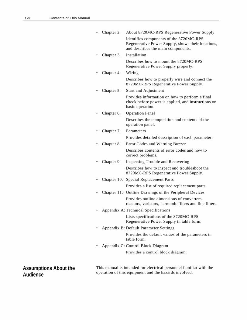
• Chapter 2: About 8720MC-RPS Regenerative Power Supply
Identifies components of the 8720MC-RPSRegenerative Power Supply, shows their locations,and describes the main components.
• Chapter 3: Installation
Describes how to mount the 8720MC-RPSRegenerative Power Supply properly.
• Chapter 4: Wiring
Describes how to properly wire and connect the8720MC-RPS Regenerative Power Supply.
• Chapter 5: Start and Adjustment
Provides information on how to perform a finalcheck before power is applied, and instructions onbasic operation.
• Chapter 6: Operation Panel
Describes the composition and contents of theoperation panel.
• Chapter 7: Parameters
Provides detailed description of each parameter.
• Chapter 8: Error Codes and Warning Buzzer
Describes contents of error codes and how tocorrect problems.
• Chapter 9: Inspecting Trouble and Recovering
Describes how to inspect and troubleshoot the8720MC-RPS Regenerative Power Supply.
• Chapter 10: Special Replacement Parts
Provides a list of required replacement parts.
• Chapter 11: Outline Drawings of the Peripheral Devices
Provides outline dimensions of converters,reactors, varistors, harmonic filters and line filters.
• Appendix A: Technical Specifications
Lists specifications of the 8720MC-RPSRegenerative Power Supply in table form.
• Appendix B: Default Parameter Settings
Provides the default values of the parameters intable form.
• Appendix C: Control Block Diagram
Provides a control block diagram.
This manual is intended for electrical personnel familiar with theoperation of this equipment and the hazards involved.
1-2 Contents of This Manual
Assumptions About theAudience

1-3Contents of This Manual
Notes on Handling the8720MC-RPS RegenerativePower Supply
The following three labels are put on the 8720MC-RPSRegenerative Power Supply, advising the user of the notes onhandling the unit. Read and understand the contents before usingthe unit.
CAUTION!PWR!
WHEN YOU APPLY POWERAGAIN, VERIFY THATTHIS LAMP "PWR" ISTURNED OFF. M
E-B
6013
DANGER!
RISK OF ELECTRICAL SHOCK. DISCONNECT INPUTPOWER BEFORE SERVICING EQUIPMENT.
ME
-B60
15
CAUTION !THIS EQUIPMENT MUST BE MOUNTED IN A SUITABLE
UL RECOGNIZED ENCLOSURE OR NEMA ENCLOSURE.
USE COPPER 60/75 DEGREE C WIRE ONLY.

1-4 Contents of This Manual
End of Chapter
Chapter 2
Model Numbers of the 8720MC-RPS Regenerative PowerSupply and its Accessories
About 8720MC-RPS Regenerative Power Supply
This chapter describes model numbers, major components, theirlocations, and terminal blocks of 8720MC-RPS Regenerative PowerSupply.
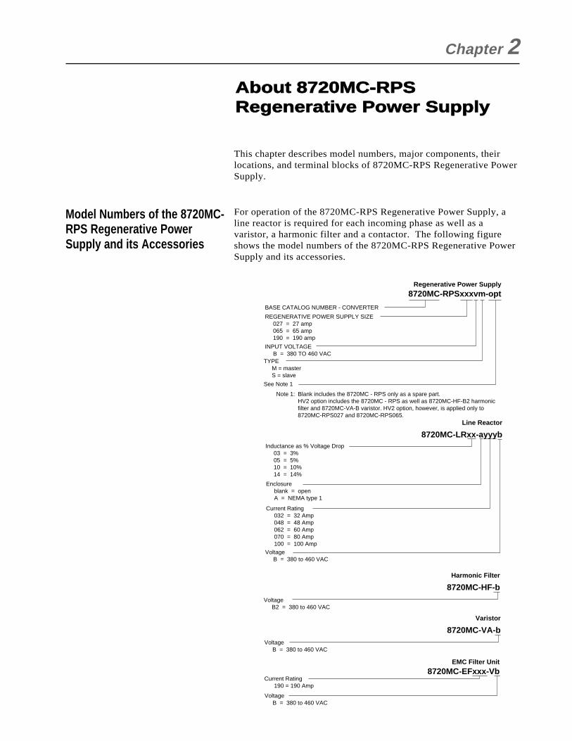
For operation of the 8720MC-RPS Regenerative Power Supply, aline reactor is required for each incoming phase as well as avaristor, a harmonic filter and a contactor. The following figureshows the model numbers of the 8720MC-RPS Regenerative PowerSupply and its accessories.
Regenerative Power Supply
8720MC-RPSxxxvm-opt
BASE CATALOG NUMBER - CONVERTER
REGENERATIVE POWER SUPPLY SIZE 027 = 27 amp 065 = 65 amp 190 = 190 amp
Inductance as % Voltage Drop 03 = 3% 05 = 5% 10 = 10% 14 = 14%
INPUT VOLTAGE B = 380 TO 460 VACTYPE M = master S = slave
Enclosure blank = open A = NEMA type 1
Current Rating 032 = 32 Amp 048 = 48 Amp 062 = 60 Amp 070 = 80 Amp 100 = 100 AmpVoltage B = 380 to 460 VAC
Voltage B2 = 380 to 460 VAC
See Note 1
Note 1: Blank includes the 8720MC - RPS only as a spare part. HV2 option includes the 8720MC - RPS as well as 8720MC-HF-B2 harmonic filter and 8720MC-VA-B varistor. HV2 option, however, is applied only to
8720MC-RPS027 and 8720MC-RPS065.Line Reactor
8720MC-LRxx-ayyyb
Harmonic Filter
8720MC-HF-b
Voltage B = 380 to 460 VAC
Varistor
8720MC-VA-b
Voltage B = 380 to 460 VAC
EMC Filter Unit
8720MC-EFxxx-VbCurrent Rating 190 = 190 Amp
2-2 About 8720MC-RPS Regenerative Power Supply
Power Rating
Appearance of the 8720MC-RPS Regenerative PowerSupply
Power Rating
15 kW
37 kW
75 kW
110 kW
125 kW
250 kW
375 kW
Kind of Unit
15 kW
37 kW
125 kW
Connection
Single Unit
Single Unit
Two paralleled units
Three paralleled units
Single Unit
Two paralleled units
Three paralleled units
Model Number
8720MC-RPS027BM x 1
8720MC-RPS065BM x 1
8720MC-RPS065BM +8720MC-RPS065BS x 1
8720MC-RPS065BM +8720MC-RPS065BS x 2
8720MC-RPS190BM x 1
8720MC-RPS190BM +8720MC-RPS190BS x 1
8720MC-RPS190BM +8720MC-RPS190BS x 2
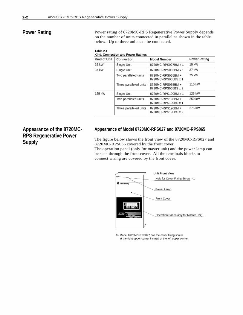
Hole for Cover Fixing Screw <1
Power Lamp
Front Cover
Operation Panel (only for Master Unit)REGENERATIVE POWER SUPPLYREGENERATIVE POWER SUPPLY
8720 MCMC
RST PRG ENT
READYREADY
FAULTFAULT
PROGRAMPROGRAM kWkW
V
A
1> Model 8720MC-RPS027 has the cover fixing screw at the right upper corner instead of the left upper corner.
Unit Front View
Appearance of Model 8720MC-RPS027 and 8720MC-RPS065
The figure below shows the front view of the 8720MC-RPS027 and8720MC-RPS065 covered by the front cover.The operation panel (only for master unit) and the power lamp canbe seen through the front cover. All the terminals blocks toconnect wiring are covered by the front cover.
Table 2.1Kind, Connection and Power Ratings
Power rating of 8720MC-RPS Regenerative Power Supply dependson the number of units connected in parallel as shown in the tablebelow. Up to three units can be connected.
About 8720MC-RPS Regenerative Power Supply 2-3
RST PRG ENT
POWER
READYREADY
FAULTFAULT
PROGRAMPROGRAM kWkW
V
A
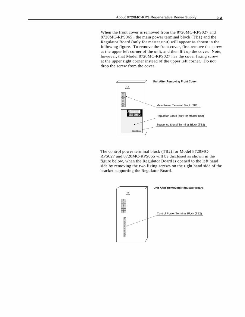
Main Power Terminal Block (TB1)
Regulator Board (only for Master Unit)
Sequence Signal Terminal Block (TB3)
Unit After Removing Front Cover
POWER
Control Power Terminal Block (TB2)
Unit After Removing Regulator Board
When the front cover is removed from the 8720MC-RPS027 and8720MC-RPS065 , the main power terminal block (TB1) and theRegulator Board (only for master unit) will appear as shown in thefollowing figure. To remove the front cover, first remove the screwat the upper left corner of the unit, and then lift up the cover. Note,however, that Model 8720MC-RPS027 has the cover fixing screwat the upper right corner instead of the upper left corner. Do notdrop the screw from the cover.
The control power terminal block (TB2) for Model 8720MC-RPS027 and 8720MC-RPS065 will be disclosed as shown in thefigure below, when the Regulator Board is opened to the left handside by removing the two fixing screws on the right hand side of thebracket supporting the Regulator Board.
2-4 About 8720MC-RPS Regenerative Power Supply
Hole for Cover Fixing Screw
Power Lamp
Front Cover
Operation Panel (only for Master Unit)REGENERATIVE POWER SUPPLYREGENERATIVE POWER SUPPLY
87208720 MCMC
RST PRG ENT
READY
FAULT
PROGRAM kW
V
A
P N DC Bus Terminals
Main Power TerminalsL2 L1 L3
Unit Front View
Unit After Removing Front Cover
Control Power Terminak Block (TB2)
Control Terminal Block (TB4)
Regulator Board (only for Master Unit)RST PRG ENT
READY
FAULT
PROGRAM kW
V
A
Sequence Signal Terminal Block (TB3)
L1AUX
L2AUX
L3AUX
PR1PR2PR3
+24V30V3SENS+24V20V2MC1MC2
Fuse1
Fuse2
Fuse3
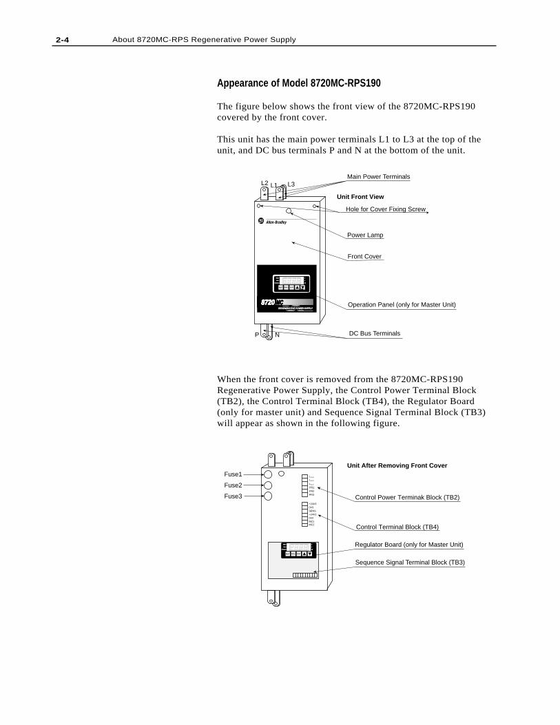
Appearance of Model 8720MC-RPS190
The figure below shows the front view of the 8720MC-RPS190covered by the front cover.
This unit has the main power terminals L1 to L3 at the top of theunit, and DC bus terminals P and N at the bottom of the unit.
When the front cover is removed from the 8720MC-RPS190Regenerative Power Supply, the Control Power Terminal Block(TB2), the Control Terminal Block (TB4), the Regulator Board(only for master unit) and Sequence Signal Terminal Block (TB3)will appear as shown in the following figure.
About 8720MC-RPS Regenerative Power Supply 2-5
Main Components andLocations
Unit Front Side
8
73
1
5
2
6
4
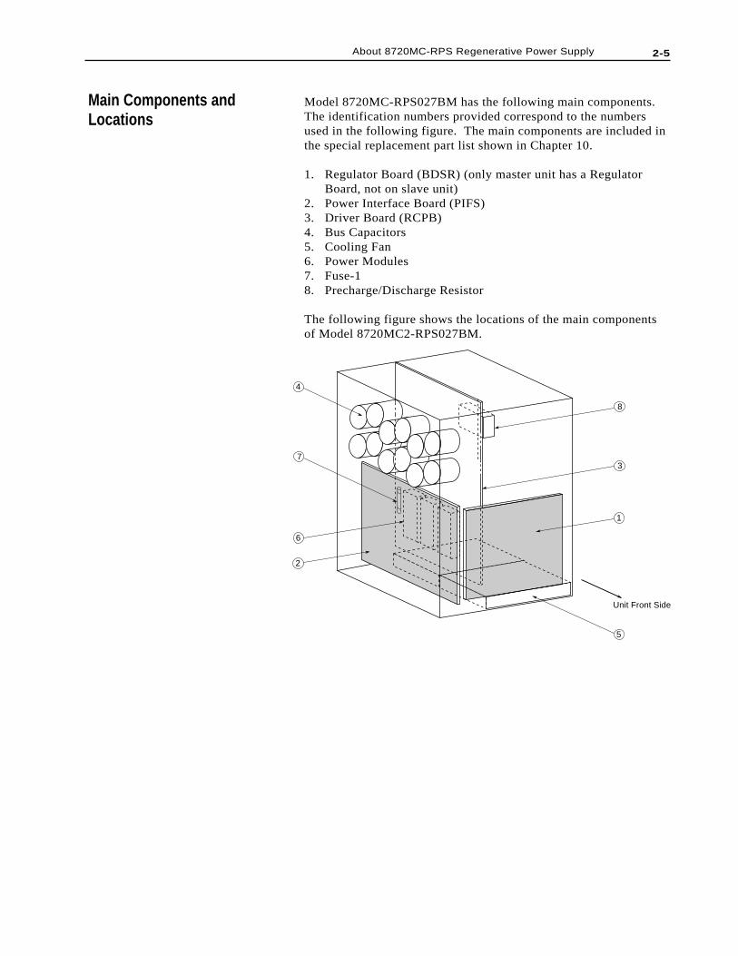
Model 8720MC-RPS027BM has the following main components.The identification numbers provided correspond to the numbersused in the following figure. The main components are included inthe special replacement part list shown in Chapter 10.
1. Regulator Board (BDSR) (only master unit has a RegulatorBoard, not on slave unit)
2. Power Interface Board (PIFS)3. Driver Board (RCPB)4. Bus Capacitors5. Cooling Fan6. Power Modules7. Fuse-18. Precharge/Discharge Resistor
The following figure shows the locations of the main componentsof Model 8720MC2-RPS027BM.
2-6 About 8720MC-RPS Regenerative Power Supply
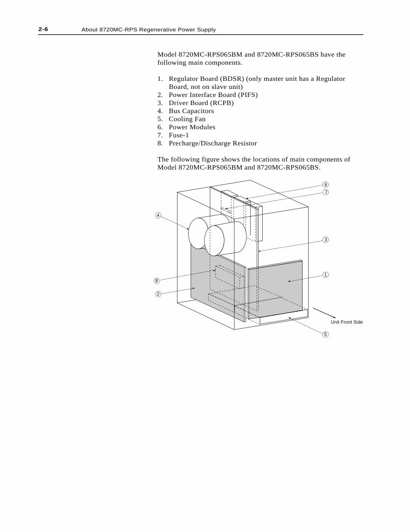
Model 8720MC-RPS065BM and 8720MC-RPS065BS have thefollowing main components.
1. Regulator Board (BDSR) (only master unit has a RegulatorBoard, not on slave unit)
2. Power Interface Board (PIFS)3. Driver Board (RCPB)4. Bus Capacitors5. Cooling Fan6. Power Modules7. Fuse-18. Precharge/Discharge Resistor
The following figure shows the locations of main components ofModel 8720MC-RPS065BM and 8720MC-RPS065BS.
Unit Front Side
4
6
7
3
1
5
2
8
2-7About 8720MC-RPS Regenerative Power Supply
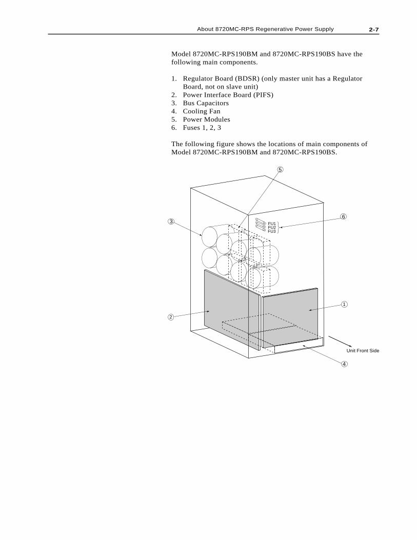
Model 8720MC-RPS190BM and 8720MC-RPS190BS have thefollowing main components.
1. Regulator Board (BDSR) (only master unit has a RegulatorBoard, not on slave unit)
2. Power Interface Board (PIFS)3. Bus Capacitors4. Cooling Fan5. Power Modules6. Fuses 1, 2, 3
The following figure shows the locations of main components ofModel 8720MC-RPS190BM and 8720MC-RPS190BS.
Unit Front Side
1
2
FU1FU2FU3
6
5
3
4
2-8 About 8720MC-RPS Regenerative Power Supply
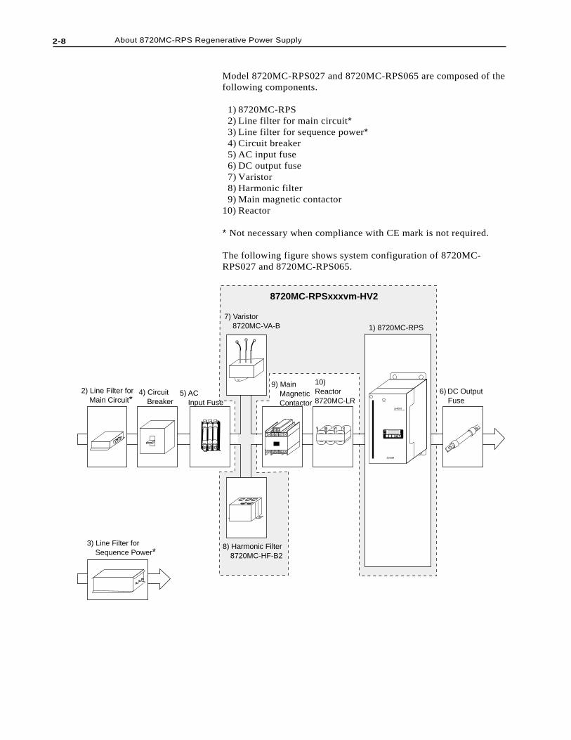
Model 8720MC-RPS027 and 8720MC-RPS065 are composed of thefollowing components.
1) 8720MC-RPS 2) Line filter for main circuit* 3) Line filter for sequence power* 4) Circuit breaker 5) AC input fuse 6) DC output fuse 7) Varistor 8) Harmonic filter 9) Main magnetic contactor10) Reactor
* Not necessary when compliance with CE mark is not required.
The following figure shows system configuration of 8720MC-RPS027 and 8720MC-RPS065.
ss4000Synchronous Rectifier
RST PRG ENT
POWER
READYREADY
FAULTFAULT
PROGRAMPROGRAM kWkW
V
A
2) Line Filter for Main Circuit*
4) Circuit Breaker
5) AC Input Fuse
6) DC Output Fuse
7) Varistor 8720MC-VA-B
9) Main Magnetic Contactor
10) Reactor8720MC-LR
1) 8720MC-RPS
8) Harmonic Filter 8720MC-HF-B2
3) Line Filter for Sequence Power*
8720MC-RPSxxxvm-HV2
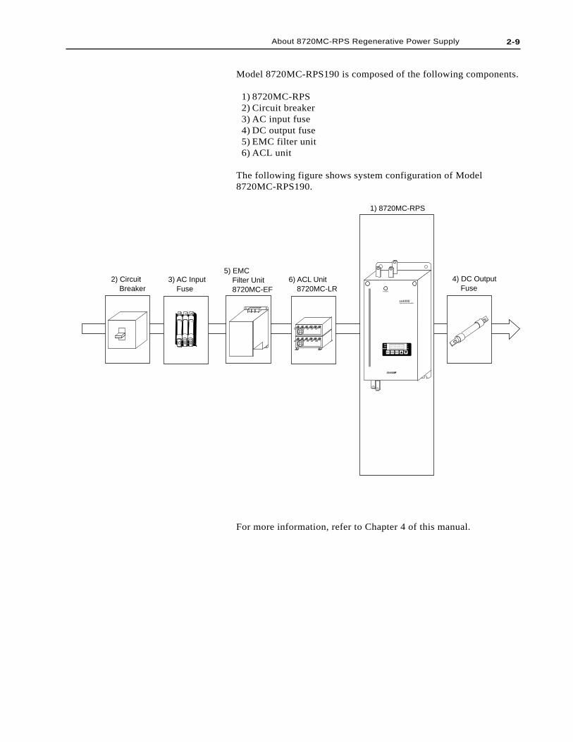
Model 8720MC-RPS190 is composed of the following components.
1) 8720MC-RPS 2) Circuit breaker 3) AC input fuse 4) DC output fuse 5) EMC filter unit 6) ACL unit
The following figure shows system configuration of Model8720MC-RPS190.
2) Circuit Breaker
3) AC Input Fuse
5) EMC Filter Unit 8720MC-EF
6) ACL Unit 8720MC-LR
4) DC Output Fuse
1) 8720MC-RPS
RST PRG ENT
READYREADY
FAULFAULT
PROGRAMPROGRAM kWkW
V
A
POWER
ss4000Synchronous Rectifier
For more information, refer to Chapter 4 of this manual.
2-9About 8720MC-RPS Regenerative Power Supply
2-10 About 8720MC-RPS Regenerative Power Supply
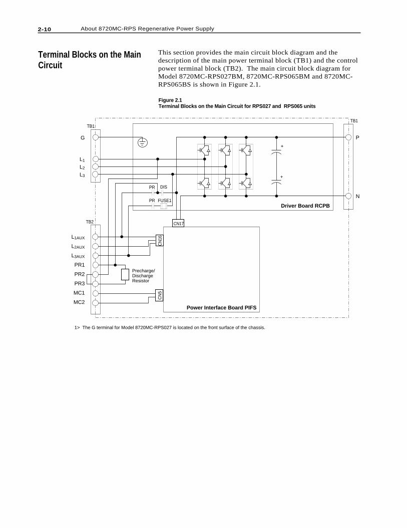
Terminal Blocks on the MainCircuit
This section provides the main circuit block diagram and thedescription of the main power terminal block (TB1) and the controlpower terminal block (TB2). The main circuit block diagram forModel 8720MC-RPS027BM, 8720MC-RPS065BM and 8720MC-RPS065BS is shown in Figure 2.1.
L1AUX
L2AUX
L3AUX
PR1
PR2
PR3
MC1
MC2
L1
L2
L3
G P
N
Driver Board RCPB
Power Interface Board PIFS
CN
16
CN17
CN
5
TB2
TB1TB1
PR DIS
PR FUSE1
Precharge/DischargeResistor
+
+
1> The G terminal for Model 8720MC-RPS027 is located on the front surface of the chassis.
Figure 2.1Terminal Blocks on the Main Circuit for RPS027 and RPS065 units
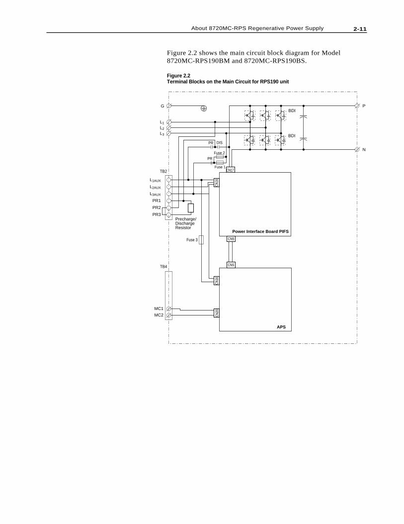
Figure 2.2 shows the main circuit block diagram for Model8720MC-RPS190BM and 8720MC-RPS190BS.
Figure 2.2Terminal Blocks on the Main Circuit for RPS190 unit
L1AUX
L2AUX
L3AUX
PR1
PR2
PR3
L1
L2
L3
G P
N
Power Interface Board PIFS
CN16
CN20
CN17
CN5
CN5
TB2
TB4
PR DIS
PRFuse 2
Fuse 1
Precharge/DischargeResistor
BDI
BDI
APS
MC1
MC2
Fuse 3
CN16
2-11About 8720MC-RPS Regenerative Power Supply
2-12 About 8720MC-RPS Regenerative Power Supply
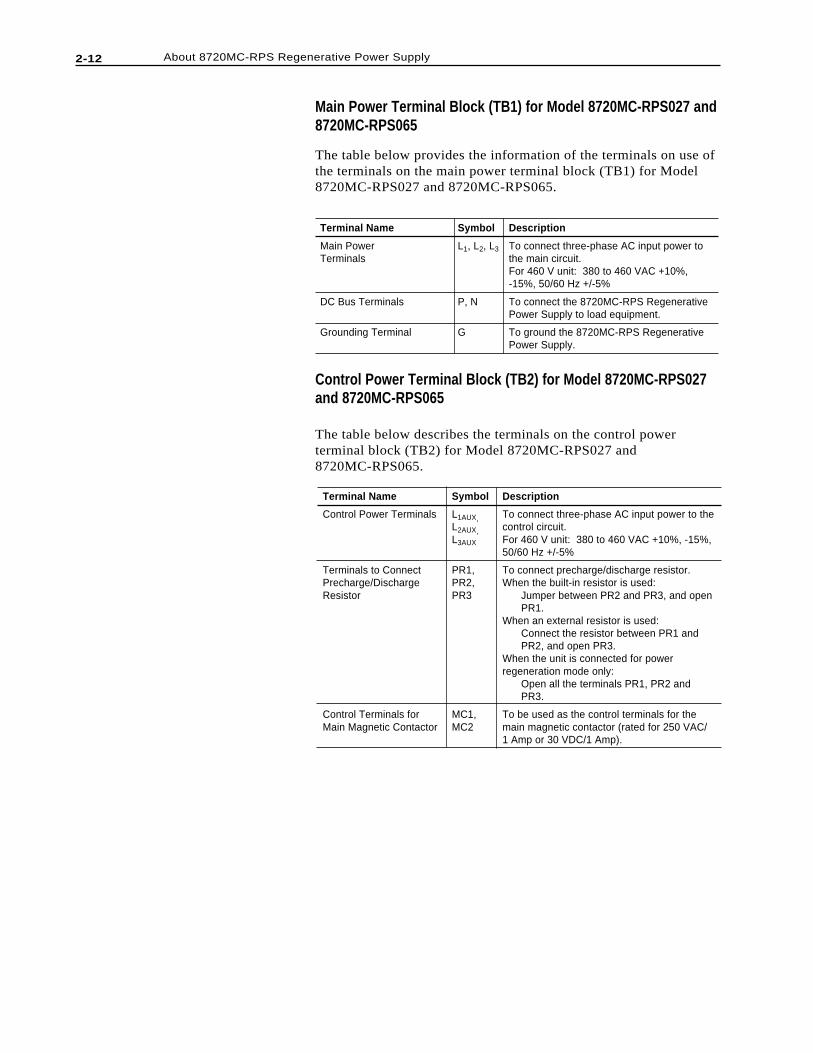
Terminal Name
Control Power Terminals
Terminals to ConnectPrecharge/DischargeResistor
Control Terminals forMain Magnetic Contactor
Symbol
L1AUX,L2AUX,L3AUX
PR1,PR2,PR3
MC1,MC2
Description
To connect three-phase AC input power to thecontrol circuit.For 460 V unit: 380 to 460 VAC +10%, -15%,50/60 Hz +/-5%
To connect precharge/discharge resistor.When the built-in resistor is used:
Jumper between PR2 and PR3, and openPR1.
When an external resistor is used:Connect the resistor between PR1 andPR2, and open PR3.
When the unit is connected for powerregeneration mode only:
Open all the terminals PR1, PR2 andPR3.
To be used as the control terminals for themain magnetic contactor (rated for 250 VAC/1 Amp or 30 VDC/1 Amp).
Control Power Terminal Block (TB2) for Model 8720MC-RPS027and 8720MC-RPS065
The table below describes the terminals on the control powerterminal block (TB2) for Model 8720MC-RPS027 and8720MC-RPS065.
Main Power Terminal Block (TB1) for Model 8720MC-RPS027 and8720MC-RPS065
The table below provides the information of the terminals on use ofthe terminals on the main power terminal block (TB1) for Model8720MC-RPS027 and 8720MC-RPS065.
Terminal Name
Main PowerTerminals
DC Bus Terminals
Grounding Terminal
Symbol
L1, L2, L3
P, N
G
Description
To connect three-phase AC input power tothe main circuit.For 460 V unit: 380 to 460 VAC +10%,-15%, 50/60 Hz +/-5%
To connect the 8720MC-RPS RegenerativePower Supply to load equipment.
To ground the 8720MC-RPS RegenerativePower Supply.
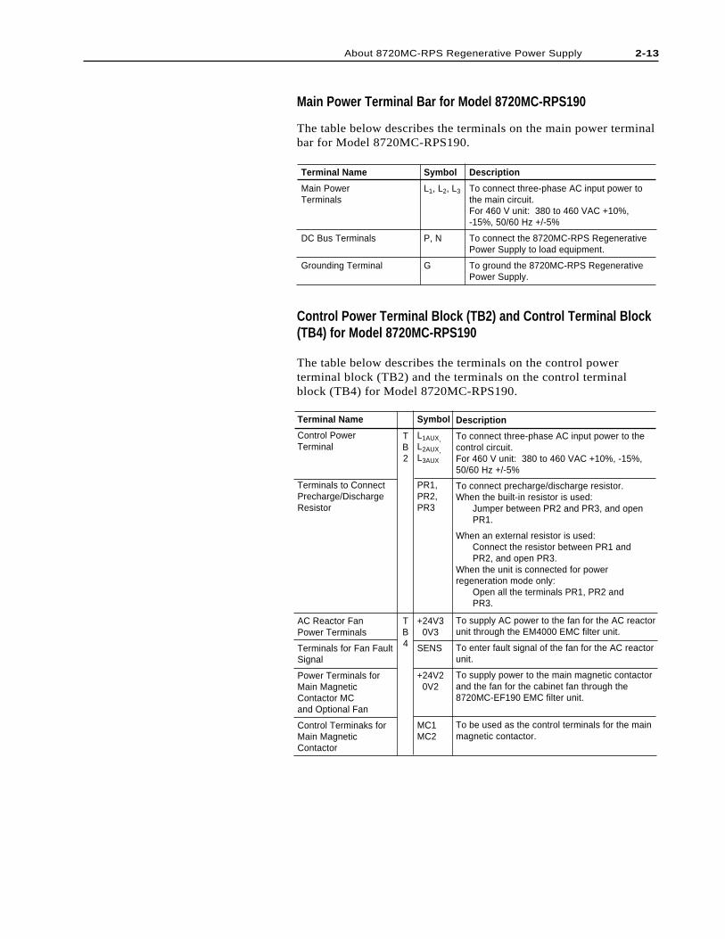
Main Power Terminal Bar for Model 8720MC-RPS190
The table below describes the terminals on the main power terminalbar for Model 8720MC-RPS190.
Terminal Name
Control PowerTerminal
Terminals to ConnectPrecharge/DischargeResistor
AC Reactor FanPower Terminals
Terminals for Fan FaultSignal
Power Terminals forMain MagneticContactor MCand Optional Fan
Control Terminaks forMain MagneticContactor
Symbol
L1AUX,L2AUX,L3AUX
PR1,PR2,PR3
+24V3 0V3
SENS
+24V2 0V2
MC1MC2
Description
To connect three-phase AC input power to thecontrol circuit.For 460 V unit: 380 to 460 VAC +10%, -15%,50/60 Hz +/-5%
To connect precharge/discharge resistor.When the built-in resistor is used:
Jumper between PR2 and PR3, and openPR1.
When an external resistor is used:Connect the resistor between PR1 andPR2, and open PR3.
When the unit is connected for powerregeneration mode only:
Open all the terminals PR1, PR2 andPR3.
To supply AC power to the fan for the AC reactorunit through the EM4000 EMC filter unit.
To enter fault signal of the fan for the AC reactorunit.
To supply power to the main magnetic contactorand the fan for the cabinet fan through the8720MC-EF190 EMC filter unit.
To be used as the control terminals for the mainmagnetic contactor.
Terminal Name
Main PowerTerminals
DC Bus Terminals
Grounding Terminal
Symbol
L1, L2, L3
P, N
G
Description
To connect three-phase AC input power tothe main circuit.For 460 V unit: 380 to 460 VAC +10%,-15%, 50/60 Hz +/-5%
To connect the 8720MC-RPS RegenerativePower Supply to load equipment.
To ground the 8720MC-RPS RegenerativePower Supply.
TB2
TB4
Control Power Terminal Block (TB2) and Control Terminal Block(TB4) for Model 8720MC-RPS190
The table below describes the terminals on the control powerterminal block (TB2) and the terminals on the control terminalblock (TB4) for Model 8720MC-RPS190.
2-13About 8720MC-RPS Regenerative Power Supply
2-14 About 8720MC-RPS Regenerative Power Supply
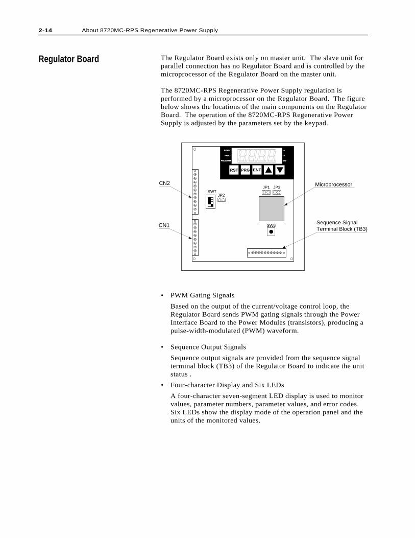
The Regulator Board exists only on master unit. The slave unit forparallel connection has no Regulator Board and is controlled by themicroprocessor of the Regulator Board on the master unit.
The 8720MC-RPS Regenerative Power Supply regulation isperformed by a microprocessor on the Regulator Board. The figurebelow shows the locations of the main components on the RegulatorBoard. The operation of the 8720MC-RPS Regenerative PowerSupply is adjusted by the parameters set by the keypad.
Regulator Board
JP1 JP3
SW6
JP2SW7
Sequence Signal Terminal Block (TB3)
CN2
CN1
RST PRG ENT
READYREADY
FAULTFAULT
PROGRAMPROGRAM kWkW
V
A
Microprocessor
• PWM Gating Signals
Based on the output of the current/voltage control loop, theRegulator Board sends PWM gating signals through the PowerInterface Board to the Power Modules (transistors), producing apulse-width-modulated (PWM) waveform.
• Sequence Output Signals
Sequence output signals are provided from the sequence signalterminal block (TB3) of the Regulator Board to indicate the unitstatus .
• Four-character Display and Six LEDs
A four-character seven-segment LED display is used to monitorvalues, parameter numbers, parameter values, and error codes.Six LEDs show the display mode of the operation panel and theunits of the monitored values.
Jumpers and Switches
ATTENTION: Only qualified electrical personnelfamiliar with the construction and operation of thisequipment and the hazards involved should setjumpers and switches. Read and understand thismanual in its entirety before proceeding. Failure toobserve this precaution could result in severe bodilyinjury or loss of life.
ATTENTION: Do not press the reset button switch(SW6) during operation. Also, do not alter the settingof any jumpers and switches during operation.Failure to observe this precaution could result indestruction of the equipment, severe bodily injury orloss of life.
ATTENTION: Do not alter the settings of anyjumpers not described in this manual. Failure toobserve this precaution could result in damage to, ordestruction of, the equipment.
The jumpers JP1 to JP3 and the switches SW6 and SW7 are setbefore shipment from factory. If you need to change the jumpersand/or switch settings, read and understand the followingdescription of these jumpers and switches before proceeding.
• Jumper JP1 to Enable Operation
Short this jumper to start switching operation of transistors ofthe 8720MC-RPS Regenerative Power Supply when the RUNsequence input is enabled. This jumper should always be keptclosed.
• Jumper JP2 to Enable Inspection Mode
Keep this jumper open always.
• Reset Switch SW6
Pressing this switch resets the CPU.
Important: Do not press the reset switch SW6 during operation.
• Switch SW7 to Enable Base Block
This switch is used to stop switching of transistors that producePWM waveform by interrupting the base signal from the PowerModules. To interrupt the base signal, turn the switch to theOFF side.
As shown in the figure below, SW7 consists of four switches,and SW7-1 to SW7-3 can be allocated to the master unit andslave units 1 and 2. In the case of a master with paralleled slaveunits, it is possible to interrupt the base signal of each unit byturning the corresponding switch to the OFF side. SW7-4 mustalways be kept to the OFF side.
!
!
!
2-15About 8720MC-RPS Regenerative Power Supply
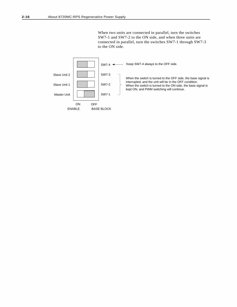
When two units are connected in parallel, turn the switchesSW7-1 and SW7-2 to the ON side, and when three units areconnected in parallel, turn the switches SW7-1 through SW7-3to the ON side.
Slave Unit 2
Slave Unit 1
Master Unit
SW7-4
SW7-3
SW7-2
SW7-1
ON OFFENABLE BASE BLOCK
Keep SW7-4 always to the OFF side.
When the switch is turned to the OFF side, the base signal is interrupted, and the unit will be in the OFF condition.When the switch is turned to the ON side, the base signal is kept ON, and PWM switching will continue.
2-16 About 8720MC-RPS Regenerative Power Supply
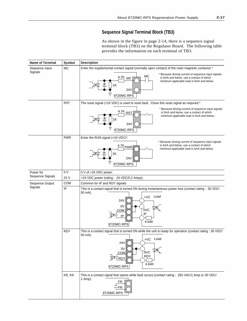
Sequence Signal Terminal Block (TB3)
As shown in the figure in page 2-14, there is a sequence signalterminal block (TB3) on the Regulator Board. The following tableprovides the information on each terminal of TB3.
Description
Enter the supplemental contact signal (normally open contact) of the main magnetic contactor.*
The reset signal (+24 VDC) is used to reset fault. Close this reset signal as required.*
Enter the RUN signal (+24 VDC)*.
0 V of +24 VDC power.
+24 VDC power (rating : 24 VDC/0.2 Amps).
Common for IP and RDY signals.
This is a contact signal that is turned ON during instantaneous power loss (contact rating : 30 VDC/50 mA).
This is a contact signal that is turned ON while the unit is ready for operation (contact rating : 30 VDC/50 mA).
This is a contact signal that opens while fault occurs (contact rating : 250 VAC/1 Amp or 30 VDC/1 Amp).
Name of Terminal
Sequence InputSignals
Power forSequence Signals
Sequence OutputSignals
Symbol
MC
RST
PWR
0 V
24 V
COM
IP
RDY
FR, FR
MCMC
24V
8720MC-RPS
4.7K
1K
RST
24V
8720MC-RPS
4.7K
1K
PWR
24V
8720MC-RPS
4.7K
1K
24V
0VCOM
IP
+VC
0VCIP
4.64K
Load
8720MC-RPS
24V
0VCOM
RDY
+VC
0VCRDY
4.64K
Load
8720MC-RPS
FR
FR
8720MC-RPS
* Because driving current of sequence input signals is 5mA and below, use a contact of which minimum applicable load is 5mA and below.
* Because driving current of sequence input signals is 5mA and below, use a contact of which minimum applicable load is 5mA and below.
* Because driving current of sequence input signals is 5mA and below, use a contact of which minimum applicable load is 5mA and below.
2-17About 8720MC-RPS Regenerative Power Supply

2-18 About 8720MC-RPS Regenerative Power Supply
End of Chapter
Chapter 3
Installation Site
Installation
!
!
This chapter shows how to mount the 8720MC-RPS RegenerativePower Supply properly, and provides information on the items to bechecked.
ATTENTION: Only qualified electrical personnelfamiliar with the construction and operation of thisequipment and the hazards involved should install,adjust, operate, or service this equipment. Read andunderstand this manual in its entirety beforeproceeding. Failure to observe this precaution couldresult in destruction of the equipment, severe bodilyinjury, or loss of life.
ATTENTION: The user is responsible for conformingwith all applicable local, national and internationalcodes. Failure to observe this precaution could resultin damage to, or destruction of, the equipment.
It is important to properly plan before installing the 8720MC-RPSRegenerative Power Supply to ensure that the environment andoperating conditions of the units are satisfactory. Read this sectionbefore continuing with the unit installation.
Environmental Conditions to be Met
The Declaration of Conformity with the requirements for CE Markwas issued for the following units, and these units must be used incabinet.
8720MC-RPS027BM,8720MC-RPS065BM, 8720MC-RPS065BS,8720MC-RPS190BM and 8720MC-RPS190BS
Also, before deciding on an installation site, consider the followingguidelines:
• Verify that the units can be kept clean, cool and dry.
• Be sure that the units are always away from oil, metal powder,other airborne contaminants, and direct sunlight.
• Check that the units will not be exposed to excessive vibrationand noise, and that they will not be close to instrumentssensitive to electrical noise.
• The area chosen should allow the space required for proper airflow as defined in the following.
3-2 Installation
• Check that the temperatures within the vicinity of the units arebetween -10 to 50 degree C (14 to 122 degree F). In case of8720MC-RPS190, however, the ambient temperature must bebetween -10 to 40 degree C (14 to 104 degree F).
• Check that the relative humidity is between 5 and 95% withoutcondensation.
• Do not install the units above 1,000 meters (3,300 feet) withoutderating output power. For every 300 meters (1,000 feet) above1,000 meters (3,300 feet), derate the output power 4%. Whenyou need to install the units above 1,500 meters (5,000 feet),contact The Allen-Bradley Company.
In case of Model 8720MC-RPS190BM and 8720MC-RPS190BS,it is possible to ship the units from the factory after mounting eachof these units in a cabinet together with the required peripheraldevices and installing wiring in the cabinet. When the userpurchases from The Allen-Bradley Company the units mounted inthe cabinet, the above-mentioned guidelines should be consideredfor selection of the installation site.
Required Total Area
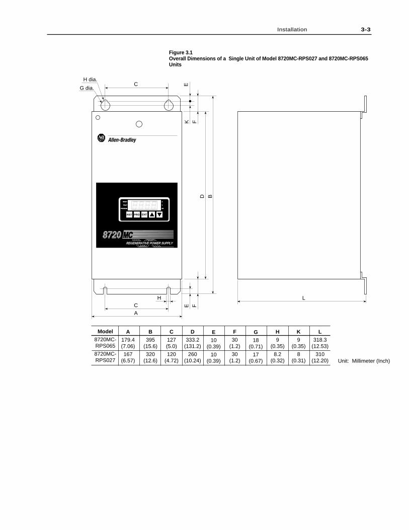
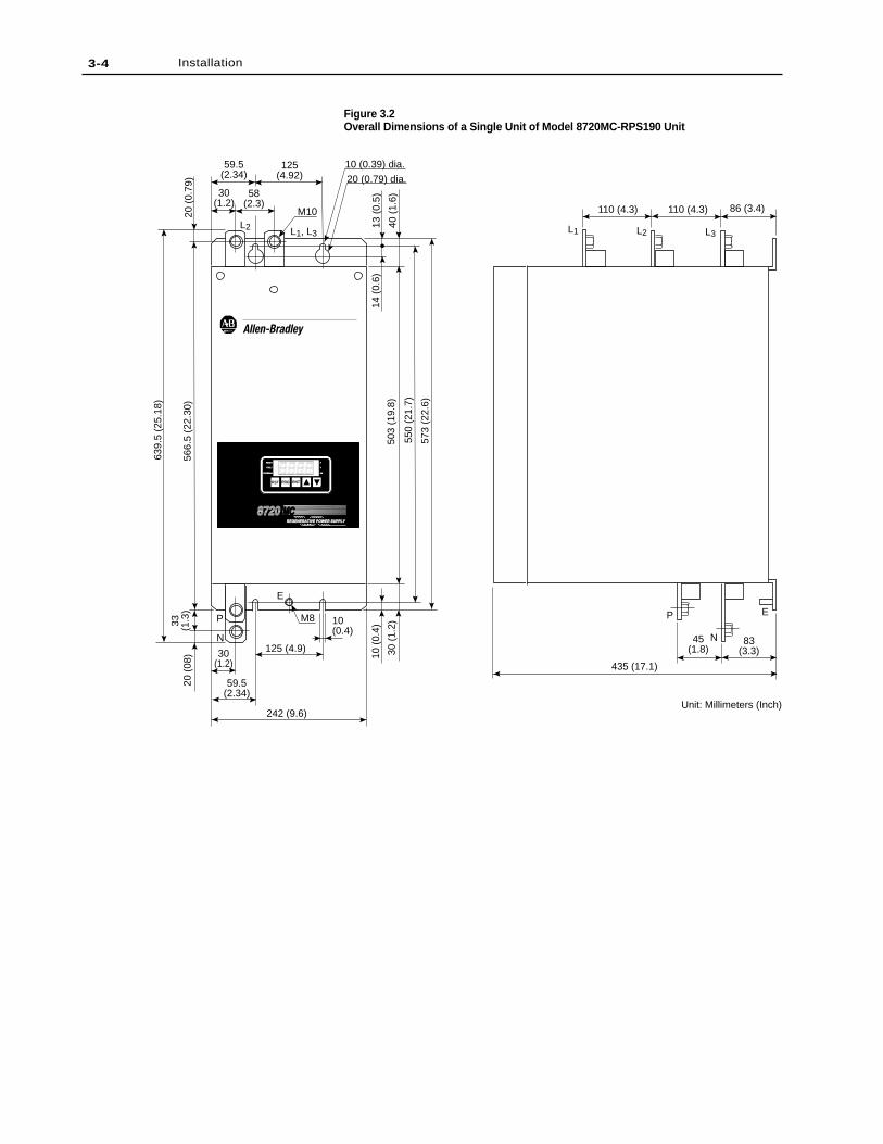
Overall unit dimensions are shown in Figures 3.1 and 3.2. Figure3.1 illustrates the dimensions of Model 8720MC-RPS027 and8720MC-RPS065 units, and Figure 3.2 shows the outlinedimensions of 8720MC-RPS190 unit. Also as an aid in calculatingthe required total area, Figures 3.3 and 3.4 show the requireddistance between two adjacent units in case of two or threeparalleled units of Model 8720MC-RPS027 and 8720MC-RPS065,and Figures 3.5 and 3.6 show the required distance between twoadjacent units in case of two or three paralleled units of Model8720MC-RPS190 unit installed in a cabinet provided by the user.
3-3Installation
Figure 3.1Overall Dimensions of a Single Unit of Model 8720MC-RPS027 and 8720MC-RPS065Units
D B
A
L
EK
F
E
F
H dia.
G dia.C
HC
Unit: Millimeter (Inch)
REGENERATIVE POWER SUPPLYREGENERATIVE POWER SUPPLY
8720 MCMC
RST PRG ENT
READYREADY
FAULTFAULT
PROGRAMPROGRAM kW
V
A
Model
8720MC-RPS065
8720MC-RPS027
A
179.4(7.06)
167(6.57)
B
395(15.6)
320(12.6)
C
127(5.0)
120(4.72)
D
333.2(131.2)
260(10.24)
E
10(0.39)
10(0.39)
F
30(1.2)
30(1.2)
G
18(0.71)
17(0.67)
H
9(0.35)
8.2(0.32)
K
9(0.35)
8(0.31)
L
318.3(12.53)
310(12.20)
3-4 Installation
Figure 3.2Overall Dimensions of a Single Unit of Model 8720MC-RPS190 Unit
110 (4.3) 110 (4.3) 86 (3.4)
L3L2L2 L1L1, L3
P
N45(1.8)
83(3.3)
435 (17.1)
242 (9.6)
59.5(2.34)
30(1.2)
125 (4.9)
10(0.4)
M8
40 (
1.6)
13 (
0.5)
14 (
0.6)
20 (
0.79
)
573
(22.
6)
550
(21.
7)
503
(19.
8)
566.
5 (2
2.30
)
639.
5 (2
5.18
)
20 (
08) 30
(1.
2)
10 (
0.4)
P
N
E
E
30(1.2)
58(2.3)
59.5(2.34)
125(4.92)
10 (0.39) dia.
20 (0.79) dia.
M10
Unit: Millimeters (Inch)
33 (1.3
)
REGENERATIVE POWER SUPPLYREGENERATIVE POWER SUPPLY
87208720 MCMC
RST PRG ENT
READYREADY
FAULFAULT
PROGRAMPROGRAM kWkW
V
A
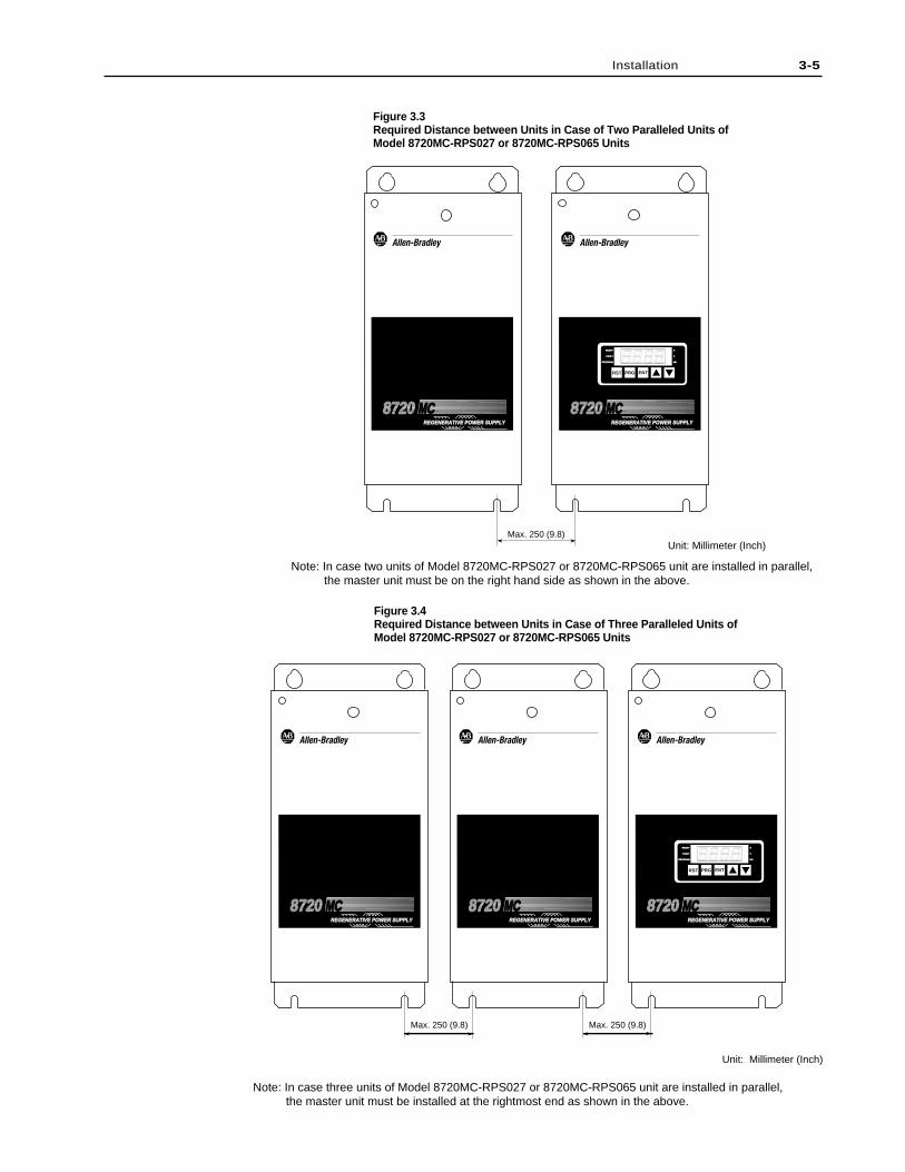
Figure 3.3Required Distance between Units in Case of Two Paralleled Units ofModel 8720MC-RPS027 or 8720MC-RPS065 Units
Figure 3.4Required Distance between Units in Case of Three Paralleled Units ofModel 8720MC-RPS027 or 8720MC-RPS065 Units
3-5Installation
Max. 250 (9.8)Max. 250 (9.8)
Unit: Millimeter (Inch)
REGENERATIVE POWER SUPPLYREGENERATIVE POWER SUPPLY
8720 MCMC
RST PRG ENT
READY
FAULT
PROGRAM kW
V
A
REGENERATIVE POWER SUPPLYREGENERATIVE POWER SUPPLY
8720 MCMCREGENERATIVE POWER SUPPLYREGENERATIVE POWER SUPPLY
8720 MCMC
Note: In case three units of Model 8720MC-RPS027 or 8720MC-RPS065 unit are installed in parallel, the master unit must be installed at the rightmost end as shown in the above.
Max. 250 (9.8)Unit: Millimeter (Inch)
REGENERATIVE POWER SUPPLYREGENERATIVE POWER SUPPLY
87208720 MC
RST PRG ENT
READYREADY
FAULTFAULT
PROGRAMPROGRAM kWkW
V
A
REGENERATIVE POWER SUPPLYREGENERATIVE POWER SUPPLY
87208720 MC
Note: In case two units of Model 8720MC-RPS027 or 8720MC-RPS065 unit are installed in parallel, the master unit must be on the right hand side as shown in the above.
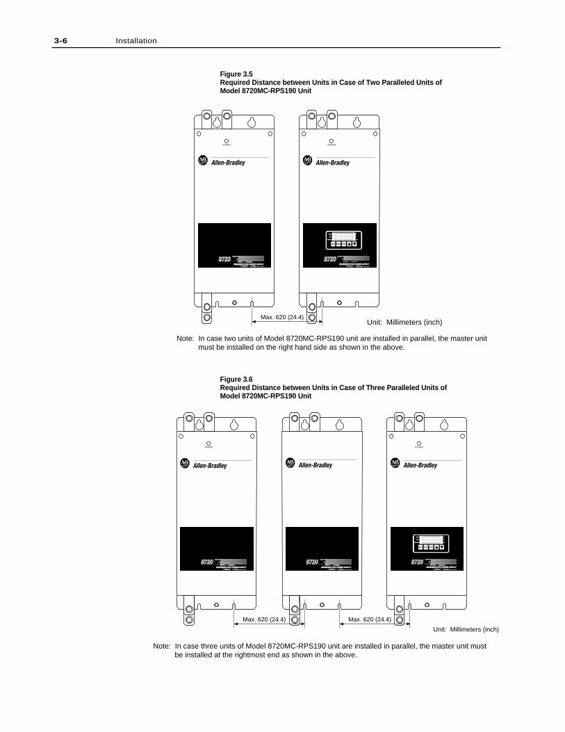
Figure 3.5Required Distance between Units in Case of Two Paralleled Units ofModel 8720MC-RPS190 Unit
Figure 3.6Required Distance between Units in Case of Three Paralleled Units ofModel 8720MC-RPS190 Unit
3-6 Installation
Max. 620 (24.4)Unit: Millimeters (inch)
POWER POWER
Note: In case two units of Model 8720MC-RPS190 unit are installed in parallel, the master unitmust be installed on the right hand side as shown in the above.
REGENERATIVE POWER SUPPLYREGENERATIVE POWER SUPPLY
87208720 MCMC
RST PRG ENT
READYREADY
FAULFAULT
PROGRAMPROGRAM kWkW
V
A
REGENERATIVE POWER SUPPLYREGENERATIVE POWER SUPPLY
87208720 MCMC
Max. 620 (24.4)
Unit: Millimeters (inch)
POWER POWER
Max. 620 (24.4)
POWER
Note: In case three units of Model 8720MC-RPS190 unit are installed in parallel, the master unit mustbe installed at the rightmost end as shown in the above.
REGENERATIVE POWER SUPPLYREGENERATIVE POWER SUPPLY
87208720 MCMC
RST PRG ENT
READYREADY
FAULFAULT
PROGRAMPROGRAM kWkW
V
A
REGENERATIVE POWER SUPPLYREGENERATIVE POWER SUPPLY
87208720 MCMCREGENERATIVE POWER SUPPLYREGENERATIVE POWER SUPPLY
87208720 MCMC
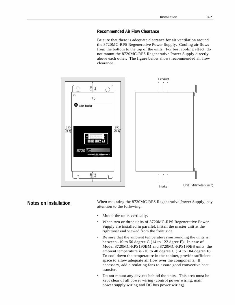
Recommended Air Flow Clearance
Be sure that there is adequate clearance for air ventilation aroundthe 8720MC-RPS Regenerative Power Supply. Cooling air flowsfrom the bottom to the top of the units. For best cooling effect, donot mount the 8720MC-RPS Regenerative Power Supply directlyabove each other. The figure below shows recommended air flowclearance.
When mounting the 8720MC-RPS Regenerative Power Supply, payattention to the following:
• Mount the units vertically.
• When two or three units of 8720MC-RPS Regenerative PowerSupply are installed in parallel, install the master unit at therightmost end viewed from the front side.
• Be sure that the ambient temperatures surrounding the units isbetween -10 to 50 degree C (14 to 122 dgree F). In case ofModel 8720MC-RPS190BM and 8720MC-RPS190BS units, theambient temperature is -10 to 40 degree C (14 to 104 degree F).To cool down the temperature in the cabinet, provide sufficientspace to allow adequate air flow over the components. Ifnecessary, add circulating fans to assure good convective heattransfer.
• Do not mount any devices behind the units. This area must bekept clear of all power wiring (control power wiring, mainpower supply wiring and DC bus power wiring).
Notes on Installation
150
(5.9
)15
0(5
.9)
150(5.9)
150(5.9)
Exhaust
Intake Unit: Millimeter (Inch)
REGENERATIVE POWER SUPPLYREGENERATIVE POWER SUPPLY
8720 MCMC
RST PRG ENT
READY
FAULT
PROGRAMPROGRAM kW
V
A
Installation 3-7

3-8 Installation
• Do not expose the units to excessive electrical noise. If it is notavoidable to install the 8720MC-RPS Regenerative PowerSupply close to a noise source or to use the units in environmentwhere noise trouble is expected, take sufficient noisesuppression measures.
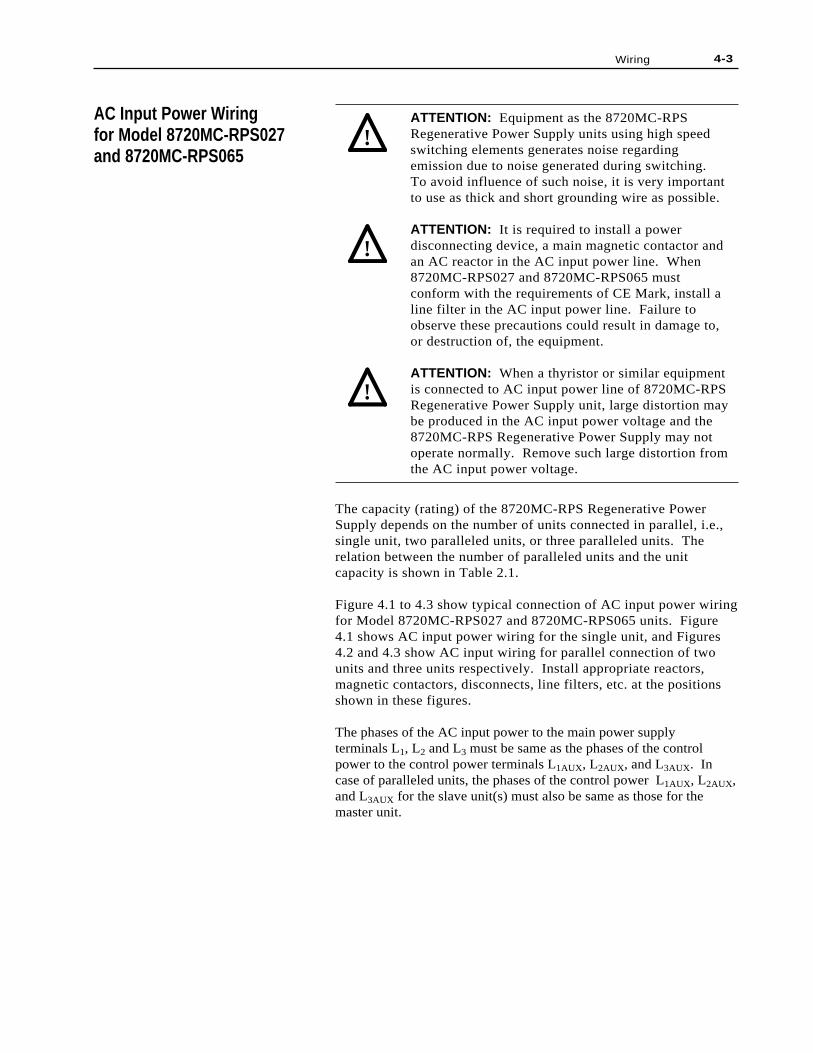
This chapter provides instructions on how to properly wire the8720MC-RPS Regenerative Power Supply units. It also providesinformation on the selection of the circuit breaker, the mainmagnetic contactor, reactor, and the harmonic filter, etc.
ATTENTION: Only qualified electrical personnelfamiliar with the construction and operation of thisequipment and the hazards involved should install,adjust, operate, or service this equipment. Read andunderstand this manual in its entirety beforeproceeding. Failure to observe this precaution couldresult in destruction of the equipment, severe bodilyinjury or loss of life.
ATTENTION: The user is responsible for conformingwith all the applicable codes. Wiring practices,grounding, disconnects, and overcurrent protectionare of particular importance. Failure to observe thisprecaution could result in severe bodily injury or lossof life.
ATTENTION: Do not use a megger to performcontinuity checks in the equipment. Use higher rangeof a circuit tester for this purpose. Failure to observethis precaution could result in damage to, ordestruction of, the equipment.
ATTENTION: The user is responsible for conformingwith all applicable local, national and internationalcodes. Failure to observe this precaution could resultin damage to, or destruction of, the equipment.
This section shows the recommended wire sizes for the wires to beused in cabinet. Select the wire sizes in consideration of thefollowing:
• Applicable local, national and international codes.
• Temperature increase and voltage drop due to type of wires,wiring method, wiring distance, etc.
Chapter 4
Recommended Wire Sizes
Wiring
!
!
!
!
4-2 Wiring
Name of Terminal
Main Terminals (Input)
DC Bus Terminals (Output)
Grounding Terminal (Earth)
Symbol
L1, L2, L3
P, N
G
Size of Wire AWG/mm2
#10 / 5.5 mm2
#10 / 5.5 mm2
#10 / 5.5 mm2
Screw Size
M5
M5
M5
Name of Terminal
Main Terminals (Input)
DC Bus Terminals (Output)
Grounding Terminal (Earth)
Symbol
L1, L2, L3
P, N
G
Size of Wire AWG/mm2
#4 / 22 mm2
#4 / 22 mm2
#5 / 22 mm2
Screw Size
M6
M6
M6
Name of Terminal
Main Power SupplyTerminals
DC Bus Terminals
Grounding Terminal
Symbol
L1, L2, L3
P, N
G
Size of Wire AWG/mm2
Larger than 38mm2 - 2 in parallel(AWG #2 - 2 inparallel)
Larger than 100mm2
(AWG #4/0)
Larger than 38mm2
(AWG #2)
Screw Size
M10
M10
M8
Attached Lugs (1)
JST, R38-10(M10) (6 Pieces)
JST, R100-10(M10) (2 Pieces)
JST, R38-8 (M10)(1 Piece)
(1) UL-listed wires must be lugged by attached lugs. JST is Japan Solderless Terminal Co.
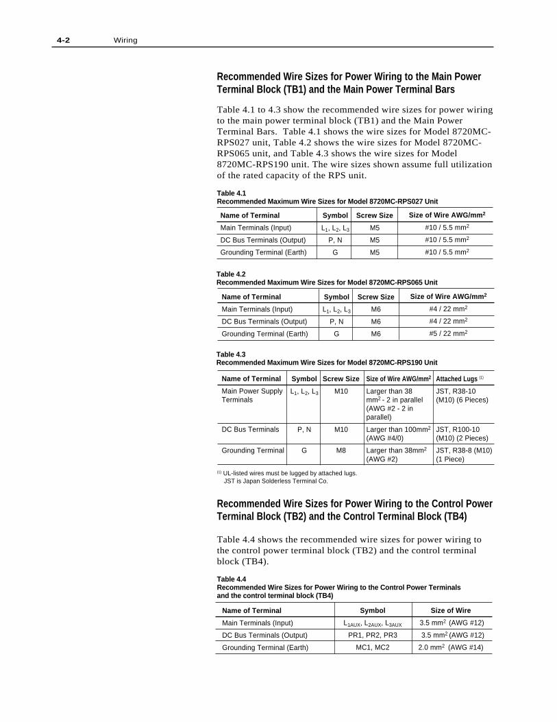
Table 4.3Recommended Maximum Wire Sizes for Model 8720MC-RPS190 Unit
Table 4.2Recommended Maximum Wire Sizes for Model 8720MC-RPS065 Unit
Recommended Wire Sizes for Power Wiring to the Main PowerTerminal Block (TB1) and the Main Power Terminal Bars
Table 4.1 to 4.3 show the recommended wire sizes for power wiringto the main power terminal block (TB1) and the Main PowerTerminal Bars. Table 4.1 shows the wire sizes for Model 8720MC-RPS027 unit, Table 4.2 shows the wire sizes for Model 8720MC-RPS065 unit, and Table 4.3 shows the wire sizes for Model8720MC-RPS190 unit. The wire sizes shown assume full utilizationof the rated capacity of the RPS unit.
Table 4.1Recommended Maximum Wire Sizes for Model 8720MC-RPS027 Unit
Recommended Wire Sizes for Power Wiring to the Control PowerTerminal Block (TB2) and the Control Terminal Block (TB4)
Table 4.4 shows the recommended wire sizes for power wiring tothe control power terminal block (TB2) and the control terminalblock (TB4).
Table 4.4Recommended Wire Sizes for Power Wiring to the Control Power Terminalsand the control terminal block (TB4)
Name of Terminal
Main Terminals (Input)
DC Bus Terminals (Output)
Grounding Terminal (Earth)
Symbol
L1AUX, L2AUX, L3AUX
PR1, PR2, PR3
MC1, MC2
Size of Wire
3.5 mm2 (AWG #12)
3.5 mm2 (AWG #12)
2.0 mm2 (AWG #14)
4-3Wiring
!
!
AC Input Power Wiringfor Model 8720MC-RPS027and 8720MC-RPS065
!
ATTENTION: Equipment as the 8720MC-RPSRegenerative Power Supply units using high speedswitching elements generates noise regardingemission due to noise generated during switching.To avoid influence of such noise, it is very importantto use as thick and short grounding wire as possible.
ATTENTION: It is required to install a powerdisconnecting device, a main magnetic contactor andan AC reactor in the AC input power line. When8720MC-RPS027 and 8720MC-RPS065 mustconform with the requirements of CE Mark, install aline filter in the AC input power line. Failure toobserve these precautions could result in damage to,or destruction of, the equipment.
ATTENTION: When a thyristor or similar equipmentis connected to AC input power line of 8720MC-RPSRegenerative Power Supply unit, large distortion maybe produced in the AC input power voltage and the8720MC-RPS Regenerative Power Supply may notoperate normally. Remove such large distortion fromthe AC input power voltage.
The capacity (rating) of the 8720MC-RPS Regenerative PowerSupply depends on the number of units connected in parallel, i.e.,single unit, two paralleled units, or three paralleled units. Therelation between the number of paralleled units and the unitcapacity is shown in Table 2.1.
Figure 4.1 to 4.3 show typical connection of AC input power wiringfor Model 8720MC-RPS027 and 8720MC-RPS065 units. Figure4.1 shows AC input power wiring for the single unit, and Figures4.2 and 4.3 show AC input wiring for parallel connection of twounits and three units respectively. Install appropriate reactors,magnetic contactors, disconnects, line filters, etc. at the positionsshown in these figures.
The phases of the AC input power to the main power supplyterminals L1, L2 and L3 must be same as the phases of the controlpower to the control power terminals L1AUX, L2AUX, and L3AUX. Incase of paralleled units, the phases of the control power L1AUX, L2AUX,and L3AUX for the slave unit(s) must also be same as those for themaster unit.
4-4 Wiring
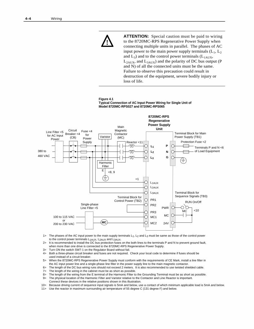
Figure 4.1Typical Connection of AC Input Power Wiring for Single Unit ofModel 8720MC-RPS027 and 8720MC-RPS065
ATTENTION: Special caution must be paid to wiringto the 8720MC-RPS Regenerative Power Supply whenconnecting multiple units in parallel. The phases of ACinput power to the main power supply terminals (L1, L2
and L3) and to the control power terminals (L1AUX,L2AUX, and L3AUX) and the polarity of DC bus output (Pand N) of all the connected units must be the same.Failure to observe this precaution could result indestruction of the equipment, severe bodily injury orloss of life.
!
MC
L1 P
L1AUX
L2AUX
L3AUX
PR1
PR2
PR3
MC1
MC2
PWR
MC
24V
8720MC-RPS RegenerativePower Supply
Unit
MC
Circuit Breaker <4
(CB)
Line Filter <5 for AC Input
Power
Single-phase Line Filter <5
MainMagneticContactor
(MC)
Reactor <11
HarmonicFilter
Terminal Block forControl Power (TB2)
100 to 115 VACor
200 to 230 VAC
380 to
460 VAC
RUN On/Off
Terminal Block for Sequence Signals (TB3)
Terminal Block for Main Power Supply (TB1)
Protection Fuse <2
Terminals P and N <6of Load Equipment
1> The phases of the AC input power to the main supply terminals L1, L2 and L3 must be same as those of the control power to the control power terminals L1AUX, L2AUX and L3AUX.
2> It is recommended to install the DC bus protection fuses on the both lines to the terminals P and N to prevent ground fault, when more than one drive is connected to the 8720MC-RPS Regenerative Power Supply. 3> Turn ON the switch SW7-1 on the Regulator Board without fail. 4> Both a three-phase circuit breaker and fuses are not required. Check your local code to determine if fuses should be used instead of a circuit breaker. 5> When the 8720MC-RPS Regenerative Power Supply must conform with the requirements of CE Mark, install a line filter in
the AC input power line and a single-phase line filter in the power supply line to the main magnetic contactor. 6> The length of the DC bus wiring runs should not exceed 2 meters. It is also recommended to use twisted shielded cable. 7> The length of the wiring in the cabinet must be as short as possible. 8> The length of the wiring from the E terminal of the Harmonic Filter to the Grounding Terminal must be as short as possible. 9> The physical location of the Harmonic Filter and Varistor relative to the Contactor and Line Reactor is important.
Connect these devices in the relative positions shown in this illustration.10> Because driving current of sequence input signals is 5mA and below, use a contact of which minimum applicable load is 5mA and below.11> Use the reactor in maximum surrounding air temperature of 55 degree C (131 degree F) and below.
Varistor
Fuse <4 for
PowerSupply
<8, 9
L3
L2
G
N
E
<10
<1
4-5Wiring
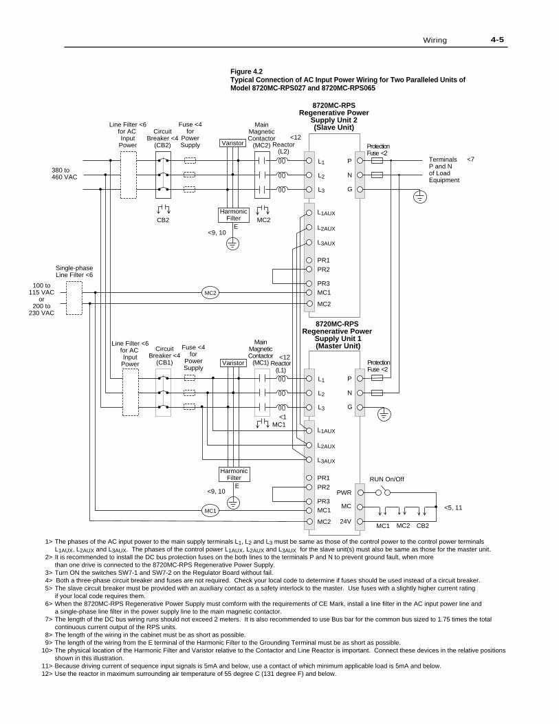
Figure 4.2Typical Connection of AC Input Power Wiring for Two Paralleled Units ofModel 8720MC-RPS027 and 8720MC-RPS065
L1
L2
L3
P
N
G
L1AUX
L2AUX
L3AUX
PR1
PR2
PR3MC1
MC2
8720MC-RPSRegenerative Power
Supply Unit 2(Slave Unit)
8720MC-RPS Regenerative Power
Supply Unit 1(Master Unit)
L1
L2
L3
P
N
G
L1AUX
L2AUX
L3AUX
PR1
PR2
PR3MC1
MC2
PWR
MC
24VMC1 CB2
CB2
MC2
RUN On/Off
MC2
MC1
MC2
MC1
Reactor(L1)
MainMagneticContactor
(MC1)
HarmonicFilter
CircuitBreaker <4
(CB1)
CircuitBreaker <4
(CB2)
Line Filter <6for AC Input
Power
Line Filter <6for AC Input
Power
Single-phaseLine Filter <6
MainMagneticContactor
(MC2) Reactor(L2)
HarmonicFilter
Protection Fuse <2
Protection Fuse <2
TerminalsP and Nof Load Equipment
380 to460 VAC
100 to115 VAC
or200 to
230 VAC
1> The phases of the AC input power to the main supply terminals L1, L2 and L3 must be same as those of the control power to the control power terminals L1AUX, L2AUX and L3AUX. The phases of the control power L1AUX, L2AUX and L3AUX for the slave unit(s) must also be same as those for the master unit.
2> It is recommended to install the DC bus protection fuses on the both lines to the terminals P and N to prevent ground fault, when more than one drive is connected to the 8720MC-RPS Regenerative Power Supply.
3> Turn ON the switches SW7-1 and SW7-2 on the Regulator Board without fail. 4> Both a three-phase circuit breaker and fuses are not required. Check your local code to determine if fuses should be used instead of a circuit breaker. 5> The slave circuit breaker must be provided with an auxiliary contact as a safety interlock to the master. Use fuses with a slightly higher current rating
if your local code requires them. 6> When the 8720MC-RPS Regenerative Power Supply must comform with the requirements of CE Mark, install a line filter in the AC input power line and
a single-phase line filter in the power supply line to the main magnetic contactor. 7> The length of the DC bus wiring runs should not exceed 2 meters. It is also recommended to use Bus bar for the common bus sized to 1.75 times the total
continuous current output of the RPS units. 8> The length of the wiring in the cabinet must be as short as possible. 9> The length of the wiring from the E terminal of the Harmonic Filter to the Grounding Terminal must be as short as possible.10> The physical location of the Harmonic Filter and Varistor relative to the Contactor and Line Reactor is important. Connect these devices in the relative positions
shown in this illustration.11> Because driving current of sequence input signals is 5mA and below, use a contact of which minimum applicable load is 5mA and below.12> Use the reactor in maximum surrounding air temperature of 55 degree C (131 degree F) and below.
Varistor
Varistor
Fuse <4for
PowerSupply
Fuse <4for
PowerSupply
<9, 10E
<9, 10E
<5, 11
<12
<1
<12
<7
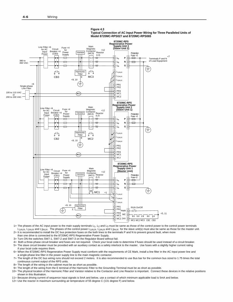
Figure 4.3Typical Connection of AC Input Power Wiring for Three Paralleled Units ofModel 8720MC-RPS027 and 8720MC-RPS065
4-6 Wiring
MC3
L1
L2
L3
P
N
G
L1AUX
L2AUX
L3AUX
PR1PR2
PR3MC1MC2
8720MC-RPSRegenerative Power
Supply Unit 3(Slave Unit 2)
8720MC-RPSRegenerative Power
Supply Unit 2(Slave Unit 1)
8720MC-RPSRegenerative Power
Supply Unit 1(Master Unit)
MC2
L1
L2
L3
P
N
G
L1AUX
L2AUX
L3AUX
PR1PR2
PR3MC1MC2
MC1
L1
L2
L3
P
N
G
L1AUX
L2AUX
L3AUX
PR1PR2
PR3MC1MC2
PWR
MC
24VMC1 MC3 CB3CB2MC2
CircuitBreaker <4
(CB3)
Line Filter <6for AC Input
Power
Line Filter <6for AC Input
Power
Line Filter <6for AC Input
Power
Single-phaseLine Filter
CircuitBreaker <4
(CB2)
CircuitBreaker <4
(CB1)
MainMagneticContactor
(MC3)
MainMagneticContactor
(MC2)
MainMagneticContactor
(MC1)
Reactor(L3)
Reactor(L2)
Reactor(L1)
380 to460 VAC
100 to 115 VACor
200 to 230 VAC
Protection Fuse <2
Protection Fuse <2
Protection Fuse <2
Terminals P and Nof Load Equipment
HarmonicFilter
RUN On/Off
1> The phases of the AC input power to the main supply terminals L1, L2 and L3 must be same as those of the control power to the control power terminals L1AUX, L2AUX and L3AUX. The phases of the control power L1AUX, L2AUX and L3AUX for the slave unit(s) must also be same as those for the master unit.
2> It is recommended to install the DC bus protection fuses on the both lines to the terminals P and N to prevent ground fault, when more than one drive is connected to the 8720MC-RPS Regenerative Power Supply.
3> Turn ON the switches SW7-1, SW7-2 and SW7-3 on the Regulator Board without fail. 4> Both a three-phase circuit breaker and fuses are not required. Check your local code to determine if fuses should be used instead of a circuit breaker. 5> The slave circuit breaker must be provided with an auxiliary contact as a safety interlock to the master. Use fuses with a slightly higher current rating
if your local code requires them. 6> When the 8720MC-RPS Regenerative Power Supply must comform with the requirements of CE Mark, install a line filter in the AC input power line and
a single-phase line filter in the power supply line to the main magnetic contactor. 7> The length of the DC bus wiring runs should not exceed 2 meters. It is also recommended to use Bus bar for the common bus sized to 1.75 times the total
continuous current output of the RPS units. 8> The length of the wiring in the cabinet must be as short as possible. 9> The length of the wiring from the E terminal of the Harmonic Filter to the Grounding Terminal must be as short as possible.10> The physical location of the Harmonic Filter and Varistor relative to the Contactor and Line Reactor is important. Connect these devices in the relative positions
shown in this illustration.11> Because driving current of sequence input signals is 5mA and below, use a contact of which minimum applicable load is 5mA and below.12> Use the reactor in maximum surrounding air temperature of 55 degree C (131 degree F) and below.
Varistor
HarmonicFilter
HarmonicFilter
Varistor
Varistor
Fuse <4for
PowerSupply
Fuse <4for
PowerSupply
Fuse <4for
PowerSupply
<9, 10
<12
<1
<12
<12
<7
<5, 11
<9, 10E
<9, 10
<6
E
E
CB2 MC2
MC1
MC3CB3
4-7Wiring
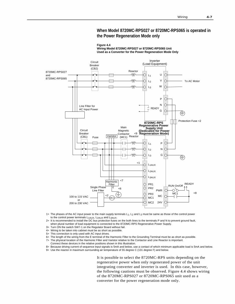
When Model 8720MC-RPS027 or 8720MC-RPS065 is operated inthe Power Regeneration Mode only
Figure 4.4Wiring Model 8720MC-RPS027 or 8720MC-RPS065 UnitUsed as a Converter for the Power Regeneration Mode Only
It is possible to select the 8720MC-RPS units depending on theregenerative power when only regenerated power of the unitintegrating converter and inverter is used. In this case, however,the following cautions must be observed. Figure 4.4 shows wiringof the 8720MC-RPS027 or 8720MC-RPS065 unit used as aconverter for the power regeneration mode only.
8720MC-RPS027and 8720MC-RPS065
MainMagneticContactor
(MC1)
MC1100 to 115 VACor
200 to 230 VAC
L1
L2
L3
P
N
G
L1AUX
L2AUX
L3AUX
PR1PR2
PR3MC1
MC2
PWR
READY
MC
24V
CircuitBreaker(CB2)
CircuitBreaker(CB1)
L1
L2
L3
MC1
RUN On/Off
U
V
W
P
N
G
To AC Motor
Reactor
Reactor
Inverter(Load Equipment)
8720MC-RPS Regenerative Power
Supply Unit(Dedicated for PowerRegeneration Mode)
HarmonicFilter
VaristorFuse
1> The phases of the AC input power to the main supply terminals L1, L2 and L3 must be same as those of the control power to the control power terminals L1AUX, L2AUX and L3AUX.
2> It is recommended to install the DC bus protection fuses on the both lines to the terminals P and N to prevent ground fault, when plural number of load equipment is connected to the 8720MC-RPS Regenerative Power Supply.
3> Turn ON the switch SW7-1 on the Regulator Board without fail.4> Wiring to be taken into cabinet must be as short as possible. 5> This connection is only used with AC input drives.6> The length of the wiring from the E terminal of the Harmonic Filter to the Grounding Terminal must be as short as possible.7> The physical location of the Harmonic Filter and Varistor relative to the Contactor and Line Reactor is important.
Connect these devices in the relative positions shown in this illustration.8> Because driving current of sequence input signals is 5mA and below, use a contact of which minimum applicable load is 5mA and below.9> Use the reactor in maximum surrounding air temperature of 55 degree C (131 degree F) and below.
Protection Fuse <2
Single PhaseLine Filter
Line Filter for AC Input Power
<1
<2
<7
<8
<9
<6E
READY

4-8 Wiring
• Rating of regenerative power of the 8720MC-RPS is less thanrated power both in the instantaneous rating and continuousrating.
• When rectifier portion of inverter is composed of thyristor, CRsnubber circuit between anode and cathode of thyristor maybecome overloaded. Therefore, treating time for regenerativepower must be within 5 seconds for 3 minutes. Because thecurrent "ICR" flowing through CR snubber circuit in the powerregeneration mode is represented by the following formula,verify the specifications of CR snubber circuit.
• Do not fail to connect ACL unit of 3% impedance towardinverter rating with the AC input line of inverter. Without ACLunit, excessive circulating current will flow between the8720MC-RPS units.
• Even during the power running, current will be supplied fromthe 8720MC-RPS unit to DC bus proportionally to the impedanceratio of both reactors at the 8720MC-RPS unit and inverter. Thiscurrent must not exceed the rating of the 8720MC-RPS unit.
• Set the parameter of the FWD Current Limit (U.001) to zero (0).
• Set the parameter of the Discharging Function Enable (F.017) tozero (OFF).
• Set the DC bus voltage to start power regeneration to theparameter of the DC Bus Voltage Reference (U.000).
• Open all the terminals PR1, PR2 and PR3 for connectingprecharge/discharge resistor. Because these terminals are open,the unit does not perform precharge/discharge operations.Precharge/discharge must be performed on inverter side.
• Do not fail to enter the READY signal of inverter to (PWR).
ICR[A] = (8 0.03 x R [Ω]) x C [µF]
4-9Wiring
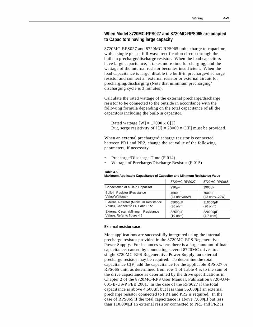
When Model 8720MC-RPS027 and 8720MC-RPS065 are adaptedto Capacitors having large capacity
8720MC-RPS027 and 8720MC-RPS065 units charge to capacitorswith a single phase, full-wave rectification circuit through thebuilt-in precharge/discharge resistor. When the load capacitorshave large capacitance, it takes more time for charging, and thewattage of the internal resistor becomes insufficient. When theload capacitance is large, disable the built-in precharge/dischargeresistor and connect an external resistor or external circuit forprecharging/discharging (Note that minimum precharging/discharging cycle is 3 minutes).
Calculate the rated wattage of the external precharge/dischargeresistor to be connected to the outside in accordance with thefollowing formula depending on the total capacitance of all thecapacitors including the built-in capacitor.
Rated wattage [W] = 17000 x C[F]But, serge resistivity of J[J] = 28000 x C[F] must be provided.
When an external precharge/discharge resistor is connectedbetween PR1 and PR2, change the set value of the followingparameters, if necessary.
• Precharge/Discharge Time (F.014)• Wattage of Precharge/Discharge Resistor (F.015)
Table 4.5Maximum Applicable Capacitance of Capacitor and Minimum Resistance Value
Capacitance of built-in Capacitor
Built-in Resistor (ResistanceValue/Wattage)
External Resistor (Minimum ResistanceValue), Connect to PR1 and PR2
External Circuit (Minimum ResistanceValue), Refer to figure 4.5
8720MC-RPS027
990µF
4500µF(33 ohm/80W)
55000µF(30 ohm)
82500µF(10 ohm)
8720MC-RPS065
1900µF
7000µF(22 ohm/120W)
110000µF(20 ohm)
220000µF(4.7 ohm)
External resistor case
Most applications are successfully integrated using the internalprecharge resistor provided in the 8720MC-RPS RegenerativePower Supply. For instances where there is a large amount of loadcapacitance, caused by connecting several 8720MC drives to asingle 8720MC-RPS Regenerative Power Supply, an externalprecharge resistor may be required. To determine the totalcapacitance C[F] add the capacitance for the applicable RPS027 orRPS065 unit, as determined from row 1 of Table 4.5, to the sum ofthe drive capacitance as determined by the drive specifications inChapter 2 of the 8720MC-RPS User Manual, Publication 8720-UM-001-B-US-P FEB 2001. In the case of the RPS027 if the totalcapacitance is above 4,500µf, but less than 55,000µf an externalprecharge resistor connected to PR1 and PR2 is required. In thecase of RPS065 if the total capacitance is above 7,000µf but lessthan 110,000µf an external resistor connected to PR1 and PR2 is
Wiring4-10
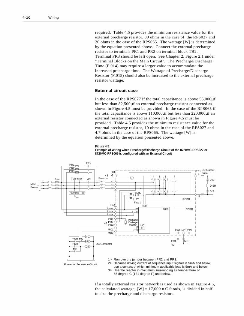
If a totally external resistor network is used as shown in Figure 4.5,the calculated wattage, [W] = 17,000 x C farads, is divided in halfto size the precharge and discharge resistors.
required. Table 4.5 provides the minimum resistance value for theexternal precharge resistor, 30 ohms in the case of the RPS027 and20 ohms in the case of the RPS065. The wattage [W] is determinedby the equation presented above. Connect the external prechargeresistor to terminals PR1 and PR2 on terminal block TB2.Terminal PR3 should be left open. See Chapter 2, Figure 2.1 under"Terminal Blocks on the Main Circuit". The Precharge/DischargeTime (F.014) may require a larger value to accommodate theincreased precharge time. The Wattage of Precharge/DischargeResistor (F.015) should also be increased to the external prechargeresistor wattage.
External circuit case
In the case of the RPS027 if the total capacitance is above 55,000µfbut less than 82,500µf an external precharge resistor connected asshown in Figure 4.5 must be provided. In the case of the RPS065 ifthe total capacitance is above 110,000µf but less than 220,000µf anexternal resistor connected as shown in Figure 4.5 must beprovided. Table 4.5 provides the minimum resistance value for theexternal precharge resistor, 10 ohms in the case of the RPS027 and4.7 ohms in the case of the RPS065. The wattage [W] isdetermined by the equation presented above.
Figure 4.5Example of Wiring when Precharge/Discharge Circuit of the 8720MC-RPS027 or8720MC-RPS065 is configured with an External Circuit
Precharge/DischargeResistor
Power for Sequence Circuit
<3
<2
<1
1> Remove the jumper between PR2 and PR3.2> Because driving current of sequence input signals is 5mA and below,
use a contact of which minimum applicable load is 5mA and below.3> Use the reactor in maximum surrounding air temperature of
55 degree C (131 degree F) and below.
MainPower
MC
MC
MC
MCPWR
PWR
RCPB
CN
15C
N5
CN17
PIFS
DIS
PR2
PRX
PR3
PR1
PR
PR
Fuse 1
DC Output Fuse
Fuse
G
L3AUX
L2AUX
L1AUX
L3
L2
L1
TB2
MC1MC2
PRX
PWR
MC
MC
PR3PR2PR1
TB1
E
TB1
DISR
DIS
DIS
N
P
24V
BDSR
Harmonic Filter
MC
DIS
PRXDC Contactor
Varistor Reactor
4-11Wiring
Parameter F.015 should be set to the sum of the wattage for bothresistors.
Installing Circuit Breaker
To protect the AC input power, install a circuit breaker withsupplemental contact (CB) in the AC input power line. Refer toFigures 4.1 to 4.3 for the wiring. The rated ampacities of thecircuit breakers are as follows:
For Model 8720MC-RPS027BM unit : 50 AmpsFor Model 8720MC-RPS065BM and8720MC-RPS065BS units : 100 Amps
The following are the recommended circuit breakers withsupplemental contact.
For Model 8720MC-RPS027BM unit:
Fuji Electric - SA100BA/50WD BU3ESB-50 W (UL-listed)*
Westinghouse - FDB3050*or equivalent
For Model 8720MC-RPS065BM and 8720MC-RPS065BS units:
Fuji Electric - SA100BA/100WD BU3ESB-100 W (UL-listed)*
Westinghouse - FDB3100*or equivalent
* Because supplemental contact of this circuit breaker does notconform with load of 5mA, relay with less than 5mA should beused for connection when a supplemental contact is connectedwith sequence input PWR.
Be sure to provide required quantity of circuit breakers withsupplemental contact (CB) for all units connected in parallel (seeFigure 4.2 or 4.3).
Installing Main Magnetic Contactor
The 8720MC-RPS Regenerative Power Supply uses a magneticcontactor for turning the main power supply ON/OFF. Install andwire the main magnetic contactors as shown in Figure 4.1 to 4.4.After the RUN sequence signal entered and the precharge operationis completed, the main magnetic contactor will be turned ON.Conversely, when the RUN sequence signal is turned OFF, or whena fault occurs, the main magnetic contactor will be turned OFF andthe discharge operation will begin.
The following are the recommended main magnetic contactors.
For Model 8720MC-RPS027BM unit:
Allen-Bradley - 100-C23x10 or 100-C30x10 (CE marked) (where x is voltage suffix code of operating coil)
Fuji Electric - SC-N1 (UL listed component)
4-12 Wiring
The 8720MC-RPS Regenerative Power Supply boosts up andcontrols the DC bus voltage, by utilizing the magneticcharacteristics of a reactor. Therefore, reactors are required for the8720MC-RPS Regenerative Power Supply.
Install a single-phase type reactor to each of L1-phase, L2-phase andL3-phase. Do not use three-phase AC reactors, since this will causeunwanted coupling between the phases.
The following inductance of the reactor must be maintained in ahigh frequency as 10 to 20 kHz. Note that use of a reactor forcommercial power supply may not maintain the requiredinductance, resulting in increased heat generation or saturation dueto iron loss.
When multiple units are connected in parallel, a current unbalancebetween the units is produced due to variation of reactorinductance. To make the current difference between the connectedunits as small as possible, use reactors having a variation of nomore than +/-2.5%.
!
!
For Model 8720MC-RPS065BM and 8720MC-RPS065BS units:
Allen-Bradley - 100-C43x10 (CE marked) (where x is voltage suffix code of operating coil)
Fuji Electric - SC-N2S (UL listed component)
(Select an adequate operating coil for the magnetic contactorwithin the range of 100 to 230 VAC depending on the usedvoltage.)
Be sure to provide required quantity of magnetic contactors (MC)for all units connected in parallel (see Figure 4.2 or 4.3).
Installing Reactor
ATTENTION: During operation of the 8720MC-RPSRegenerative Power Supply, the reactor is at a hightemperature. Do not touch the reactor duringoperation or immediately after the unit has beenturned OFF. Failure to observe this precaution couldresult in bodily injury.
ATTENTION: During operation of the 8720MC-RPSRegenerative Power Supply, the reactor operates at ahigh temperature. Install the reactor in a locationwhere high temperature does not present a problem.
Wiring 4-13
The following are the designated reactors. These reactors areintegrated for three phases consisting of three single phase reactors.When selected reactors are installed, set their capacity to theparameter F.013.
Model 8720MC-LR14-070B (1200 micro-henry): For Model 8720MC-RPS065BM and 8720MC-RPS065BS units that are used at 80 Amps or less (capacity of applicable motor is 37 kW or less)
Model 8720MC-LR10-062B (1100 micro-henry):For Model 8720MC-RPS065BM and8720MC-RPS065BS units that are used at 60 Amps orless (capacity of applicable motor is 30 kW or less).
Model 8720MC-LR05-048B (800 micro-henry):For Model 8720MC-RPS065BM and
8720MC-RPS065BS units that are used at 48 Amps or less (capacity of applicable motor is 22 kW or less).
Model 8720MC-LR03-032B (850 micro-henry): For Model 8720MC-RPS027BM, 8720MC-RPS065BM and 8720MC-RPS065BS units that are used at 32 Amps or less (capacity of applicable motor is 15 kW or less).
The reactor should operate in an ambient temperature of 50 degreeC (122 degree F) or lower. If it is not avoidable to use a reactorabove 50 degree C (122 degree F) , decrease current 1% for every 1degree C above 50 degree C.
Select temperature rating of wire to connect a reactor as follows.
For Model 8720MC-LR14-070B reactor used with current of60 Amps or lower, and for Model 8720MC-LR10-062B,8720MC-LR05-048B and 8720MC-LR03-032B reactors,
select a temperature rating 105 degree C (221 degree F) orhigher.
For Model 8720MC-LR14-070B reactor used with a currentbetween 60 and 80 Amps, select a temperature rating 130degree C (266 degree F) or higher.
Be sure to provide required quantity of reactors for all unitsconnected in parallel (see Figure 4.2 or 4.3).
Installing Varistor
Install a varistor to absorb serge voltage between AC input powerwires. The following is the designated varistor.
For 8720MC-RPS027BM, 8720MC-RPS065BM and8720MC-RPS065BS units: 8720MC-VA-B
Be sure to provide required quantity of varistors for all unitsconnected in parallel (see Figure 4.2 or 4.3). Also be sure toconnect the varistor on the incoming AC line side of the ACcontactor.
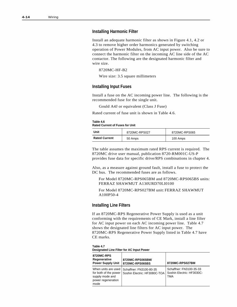
4-14 Wiring
Unit
Rated Current
8720MC-RPS027
50 Amps
8720MC-RPS065
100 Amps
The table assumes the maximum rated RPS current is required. The8720MC drive user manual, publication 8720-RM001C-US-Pprovides fuse data for specific drive/RPS combinations in chapter 4.
Also, as a measure against ground fault, install a fuse to protect theDC bus. The recommended fuses are as follows.
For Model 8720MC-RPS065BM and 8720MC-RPS065BS units:FERRAZ SHAWMUT A130URD70LI0100
For Model 8720MC-RPS027BM unit: FERRAZ SHAWMUTA100P50-4
Installing Line Filters
If an 8720MC-RPS Regenerative Power Supply is used as a unitconforming with the requirements of CE Mark, install a line filterfor AC input power on each AC incoming power line. Table 4.7shows the designated line filters for AC input power. The8720MC-RPS Regenerative Power Supply listed in Table 4.7 haveCE marks.
Installing Harmonic Filter
Install an adequate harmonic filter as shown in Figure 4.1, 4.2 or4.3 to remove higher order harmonics generated by switchingoperation of Power Modules, from AC input power. Also be sure toconnect the harmonic filter on the incoming AC line side of the ACcontactor. The following are the designated harmonic filter andwire size.
8720MC-HF-B2
Wire size: 3.5 square millimeters
Installing Input Fuses
Install a fuse on the AC incoming power line. The following is therecommended fuse for the single unit.
Gould A4J or equivalent (Class J Fuse)
Rated current of fuse unit is shown in Table 4.6.
Table 4.6Rated Current of Fuses for Unit
Table 4.7Designated Line Filter for AC Input Power
8720MC-RPSRegenerativePower Supply Unit
When units are usedfor both of the powersupply mode andpower regenerationmode
8720MC-RPS065BM/8720MC-RPS065BS
Schaffner: FN3100-80-35Soshin Electric: HF3080C-TOA
8720MC-RPS027BM
Schaffner: FN3100-35-33Soshin Electric: HF3030C-TMA
4-15Wiring
Install also a line filter on single phase AC incoming power line fora main magnetic contactor. The following are designated singlephase line filters:
For Model 8720MC-RPS027BM, 8720MC-RPS065BM and8720MC-RPS065BS units:
Schaffner FN2010-6-06 orSoshin Electric NF2005A-YX
Bus Bar and Output Fuses
When multiple drives and/or master/slave RPS units are needed fora common bus application, bus bar is recommended. Size the busbar to at least 175% of the total continuous RPS output current.The DC bus input wire and fuses to the drive can be sized to 175%of the drive continuous DC input current requirements. All fuseson the DC bus must be rated for 1,000 VDC operation. Use GouldA1-100P, Gould A1-100C (80 amps and higher) or equal. The8720MC drive user manual, publication 8720MC-RM001C-US-Pprovides DC bus fuse data for specific drive/RPS combinations inchapter 4.
ATTENTION: Equipment as the 8720MC-RPSRegenerative Power Supply units using high speedswitching elements generates noise regardingemission due to noise generated during switching.To avoid influence of such noise, it is very importantto use as thick and short grounding wire as possible.
ATTENTION: It is required to install a powerdisconnecting device, a main magnetic contactor, anAC reactor and a line filter in the AC input powerline. Failure to observe these precautions could resultin damage to, or destruction of, the equipment.
ATTENTION: When a thyristor or similar equipmentis connected to AC input power line of 8720MC-RPSRegenerative Power Supply unit, large distortion maybe produced in the AC input power voltage and the8720MC-RPS Regenerative Power Supply may notoperate normally. Remove such large distortion fromthe AC input power voltage.
The capacity (rating) of the 8720MC-RPS Regenerative PowerSupply unit depends on the number of units connected in parallel,i.e., single unit, two paralleled units, or three paralleled units. Therelation between the number of paralleled units and the unitcapacity is shown in Table 2.1.
Figure 4.6 to 4.8 show typical connection of AC input power wiringfor Model 8720MC-RPS190 unit. Figure 4.6 shows AC inputpower wiring for the single unit, and Figures 4.7 and 4.8 show ACinput wiring for parallel connection of two units and three unitsrespectively. Select appropriate ACL units (reactor assemblies),8720MC-EF190-VB EMC filter units, disconnects, etc., andinstalled them at the positions shown in these figures.
ATTENTION: When two or three paralleled units ofModel 8720MC-RPS190 unit are operated, specialcare should be paid to the countermeasure againstnoise generated by each of the paralleled units duringswitching operation. If each of the paralleled units isinstalled in a separate cabinet, be careful for selectionof cabinet and installation of the units.
ATTENTION: The temperature inside the cabinetmust be kept below 40 degree C (104 degree F).Because Model 8720MC-RPS190 unit generates largeamount of heat, exercise special caution forexhausting air. Also, be careful for selection ofinstallation location of the 8720MC-EF190-VB EMCfilter units.
4-16 Wiring
!
!
AC Input Power Wiringfor Model 8720MC-RPS190 !
!
!
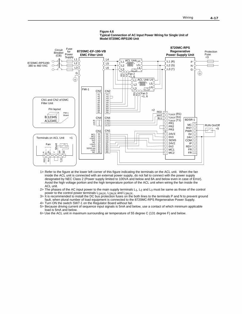
4-17Wiring
Figure 4.6Typical Connection of AC Input Power Wiring for Single Unit ofModel 8720MC-RPS190 Unit
CN2FMI-1
CN2
CN4123
CN4
CN1MC1MC2
+24V20V2NC
+24V30V3
SENS-out+24V
MC
L1 L4
L5
L6
L2
L3
L1 (R)L2 (S)L3 (T)
PNG
L1AUX (R1)L2AUX (S1)L3AUX (T1)PR1PR2PR3
ACL Unit
ACL Unit
24V30V3SENS24V20V2MC1MC2
MCRST
PWR0V
24VCOM
IPRDY
FRFR
RED
1 R12 S13 T1
WHTBLU BDSR-1
CN1
G
8720MC-RPS190: 380 to 460 VAC
L4
L5L6
L1L2L3
L4L5L6
L1
L2L3
<1, 6
<1, 6
8720MC-EF-190-VBEMC Filter Unit
8720MC-RPSRegenerative
Power Supply Unit
Fan
YLWBLK
BL
BR
BR
RE
DR Y
Sho
rt
Terminals on ACL Unit
1> Refer to the figure at the lower left corner of this figure indicating the terminals on the ACL unit. When the fan inside the ACL unit is connected with an external power supply, do not fail to connect with the power supply designated by NEC Class 2 (Power supply limited to 100VA and below and 8A and below even in case of Error).Avoid the high voltage portion and the high temperature portion of the ACL unit when wiring the fan inside the ACL unit.
2> The phases of the AC input power to the main supply terminals L1, L2 and L3 must be same as those of the control power to the control power terminals L1AUX, L2AUX and L3AUX.
3> It is recommended to install the DC bus protection fuses on the both lines to the terminals P and N to prevent groundfault, when plural number of load equipment is connected to the 8720MC-RPS Regenerative Power Supply.
4> Turn ON the switch SW7-1 on the Regulator Board without fail.5> Because driving current of sequence input signals is 5mA and below, use a contact of which minimum applicable
load is 5mA and below.6> Use the ACL unit in maximum surrounding air temperature of 55 degree C (131 degree F) and below.
Fusefor
Power Supply
CircuitBreaker
(CB)Protection Fuse <3
RUN On/Off
A1A2A3A4A5B1B2B3B4B5
A1A2A3A4A5B1B2B3B4B5
A1A2A3A4A5B1B2B3B4B5
A1A2A3A4A5B1B2B3B4B5
R1S1T1
Fan 3
Fan 2
RED
BLK
YLW
YLW
RED
BLK
<5
<2
CN1 and CN2 of EMCFilter Unit
B 12345A 12345
Pin layoutFMI-1Board
<1
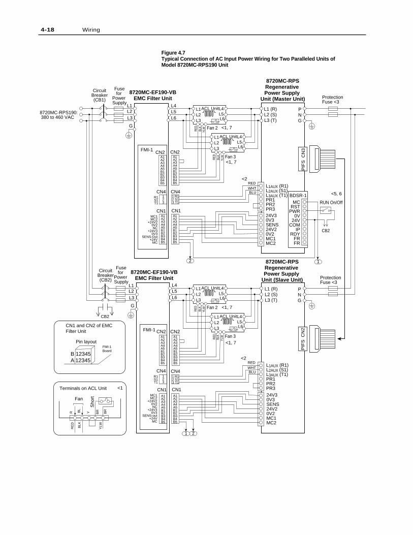
Figure 4.7Typical Connection of AC Input Power Wiring for Two Paralleled Units ofModel 8720MC-RPS190 Unit
4-18 Wiring
A1A2A3A4A5B1B2B3B4B5
A1A2A3A4A5B1B2B3B4B5
A1A2A3A4A5B1B2B3B4B5
CN2A1A2A3A4A5B1B2B3B4B5
CN2
CN4123
CN4
CN1MC1MC2
+24V20V2NC
+24V30V3
SENS-Out+24V
MC
L1 L4L5L6
L4L5L6
L2L3
L1 (R)L2 (S)L3 (T)
PNG
L1AUX (R1)L2AUX (S1)L3AUX (T1)PR1PR2PR324V30V3SENS24V20V2MC1MC2
MCRST
PWR0V
24VCOM
IPRDY
FRFR
RED
1 R12 S13 T1
WHTBLU
BDSR-1
CN1
G
L1L2L3
G
8720MC-RPS190: 380 to 460 VAC
<1, 7
<1, 7
<1, 7
<1, 7
<2
<2
<5, 6
8720MC-EF190-VBEMC Filter Unit
8720MC-EF190-VBEMC Filter Unit
8720MC-RPSRegenerative Power Supply
Unit (Master Unit)
8720MC-RPSRegenerative Power Supply
Unit (Slave Unit)
PIF
S C
N3
2
1 2
1
CircuitBreaker(CB1)
CircuitBreaker(CB2)
Fusefor
Power Supply
Fusefor
Power Supply
ACL UnitL1L2L3
L4L5L6
L1 (R)L2 (S)L3 (T)
PNG
PIF
S C
N2
CN4
CN2 CN2
CN41 R12 S13 T1
123
CN1 CN1MC1MC2
+24V20V2NC
+24V30V3
SENS-out+24V
MC
REDWHTBLU
L1AUX (R1)L2AUX (S1)L3AUX (T1)PR1PR2PR324V30V3SENS24V20V2MC1MC2
ProtectionFuse <3
ProtectionFuse <3
RUN On/OffR1S1T1
Fan 2
Fan 2
Fan 3
Fan 3A1A2A3A4A5B1B2B3B4B5
A1A2A3A4A5B1B2B3B4B5
A1A2A3A4A5B1B2B3B4B5
A1A2A3A4A5B1B2B3B4B5
R1S1T1
Fan
YLWBLK
BL
BR BR
RE
DR Y
Sho
rt
Terminals on ACL Unit
ACL UnitL1L2L3
L4L5L6
ACL UnitL1L2L3
L4L5L6
ACL UnitL1L2L3
L4L5L6
RED
YLW
YLW
YLW
YLW
BLK
RED
BLK
RED
BLK
RED
BLK
FMI-1
FMI-1CN1 and CN2 of EMCFilter Unit
B 12345A 12345
Pin layoutFMI-1Board
<1
CB2
CB2

4-19Wiring
1> Refer to the lower left corner of Figure 4.7 indicating the terminals on the ACL unit. When the fan inside the ACL unitis connected with an external power supply, do not fail to connect with the power supply designated by NEC Class 2(Power supply limited to 100VA and below, and 8A and below even in case of Error). Avoid the high voltage portionand the high temperature portion of the ACL unit when wiring the fan inside the ACL unit.
2> The phases of the AC input power to the main supply terminals L1, L2 and L3 must be same as those of the controlpower to the control power terminals L1AUX, L2AUX and L3AUX.
3> It is recommended to install the DC bus protection fuses on the both lines to terminals P and N to prevent groundfault, when plural number of load equipment is connected to the 8720MC-RPS Regenerative Power Supply.
4> Turn on the switch SW7-1 and SW7-2 on the Regulator Board without fail.5> Slave circuit breakers must be provided with an auxiliary contact as a safety interlock to the master. Use fuses with a
slightly higher current rating also if your local code requires them.6> Because driving current of sequence input signals is 5mA and below, use a contact of which minimum applicable load
is 5mA and below.7> Use the ACL unit in maximum surrounding air temperature of 55 degree C (131 degree F) and below.
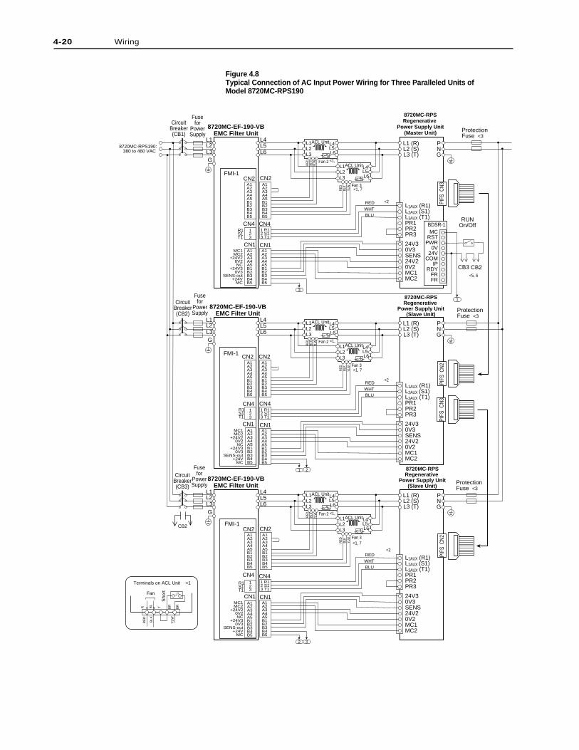
Figure 4.8Typical Connection of AC Input Power Wiring for Three Paralleled Units ofModel 8720MC-RPS190
4-20 Wiring
8720MC-RPS190: 380 to 460 VAC
8720MC-EF-190-VBEMC Filter Unit
CN2 CN2
CN4 CN4
CN1MC1MC2
+24V20V2NC
+24V30V3
SENS-out+24V
MC
L1 L4L5L6
L2L3
L1 (R)L2 (S)L3 (T)
PNG
L1AUX (R1)L2AUX (S1)L3AUX (T1)PR1PR2PR3
24V30V3SENS24V20V2MC1MC2
REDWHTBLU
CN1
G
8720MC-RPSRegenerative
Power Supply Unit(Slave Unit)
PIFS
CN2
2 3
ACL UnitL1L2L3
L4L5L6
8720MC-EF-190-VBEMC Filter Unit
L1 L4L5L6
L2L3
L1 (R)L2 (S)L3 (T)
PNG
G
8720MC-RPSRegenerative
Power Supply Unit(Slave Unit)
PIFS
CN2
1
8720MC-EF-190-VBEMC Filter Unit
L1 L4L5L6
L2L3
L1 (R)L2 (S)L3 (T)
PNG
G
8720MC-RPSRegenerative
Power Supply Unit(Master Unit)
PIFS
CN3
3
2
ProtectionFuse <3
ProtectionFuse <3
ProtectionFuse <3
PIFS
CN
3
MCRST
PWR0V
24VCOM
IPRDY
FRFR
BDSR-1
1
RUNOn/Off
CircuitBreaker(CB1)
CircuitBreaker(CB2)
CircuitBreaker(CB3)
Fusefor
PowerSupply
Fusefor
PowerSupply
Fusefor
PowerSupply
L1AUX (R1)L2AUX (S1)L3AUX (T1)PR1PR2PR3
24V30V3SENS24V20V2MC1MC2
L1AUX (R1)L2AUX (S1)L3AUX (T1)PR1PR2PR3
24V30V3SENS24V20V2MC1MC2
CN2 CN2
CN4 CN4
CN1MC1MC2
+24V20V2NC
+24V30V3
SENS-out+24V
MC
CN1
CN2 CN2
CN4 CN4
CN1MC1MC2
+24V20V2NC
+24V30V3
SENS-out+24V
MC
CN1
REDWHTBLU
REDWHTBLU
1 R12 S13 T1
1 R12 S13 T1
1 R12 S13 T1
A1A2A3A4A5B1B2B3B4B5
A1A2A3A4A5B1B2B3B4B5
A1A2A3A4A5B1B2B3B4B5
A1A2A3A4A5B1B2B3B4B5
A1A2A3A4A5B1B2B3B4B5
A1A2A3A4A5B1B2B3B4B5
A1A2A3A4A5B1B2B3B4B5
A1A2A3A4A5B1B2B3B4B5
123
123
Fan 3
Fan 2
R1S1T1
R1S1T1
A1A2A3A4A5B1B2B3B4B5
A1A2A3A4A5B1B2B3B4B5
A1A2A3A4A5B1B2B3B4B5
A1A2A3A4A5B1B2B3B4B5
R1S1T1
123
Fan
YLWBLK
RE
DR B
L
Y BR
BR
Sho
rt
Terminals on ACL Unit <1
ACL UnitL1L2L3
L4L5L6
ACL UnitL1L2L3
L4L5L6
ACL UnitL1L2L3
L4L5L6
ACL UnitL1L2L3
L4L5L6
ACL UnitL1L2L3
L4L5L6
RED
BLK
RED
BLK
Fan 3
Fan 2RE
DBL
K
RED
BLK
Fan 3
Fan 2
RED
BLK
RED
YLW
YLW
YLW
YLW
YLW
YLW
BLK
FMI-1
FMI-1
FMI-1CB2
CB3 CB2
<1, 7
<1, 7
<2
<2
<2
<1, 7
<1, 7
<1, 7
<1, 7
<5, 6
4-21Wiring
1> Refer to the lower left corner of Figure 4.7 indicating the terminals on the ACL unit. When the faninside the ACL unit is connected with an external power supply, do not fail to connect with thepower supply designated by NEC Class 2 (Power supply limited to 100VA and below, and 8A andbelow even in case of Error). Avoid the high voltage portion and the high temperature portion of theACL unit when wiring the fan inside the ACL unit.
2> The phases of the AC input power to the main supply terminals L1, L2 and L3 must be same asthose of the control power to the control power terminals L1AUX, L2AUX and L3AUX.
3> It is recommended to install the DC bus protection fuses on the both lines to terminals P and N toprevent ground fault, when plural number of load equipment is connected to the 8720MC-RPSRegenerative Power Supply.
4> Turn on the switch SW7-1, SW7-2 and SW7-3 on the Regulator Board without fail.5> Slave circuit breakers must be provided with an auxiliary contact as a safety interlock to the master.
Use fuses with a slightly higher current rating also if your local code requires them.6> Because driving current of sequence input signals is 5mA and below, use a contact of which
minimum applicable load is 5mA and below.7> Use the ACL unit in maximum surrounding air temperature of 55 degree C (131 degree F) and
below.
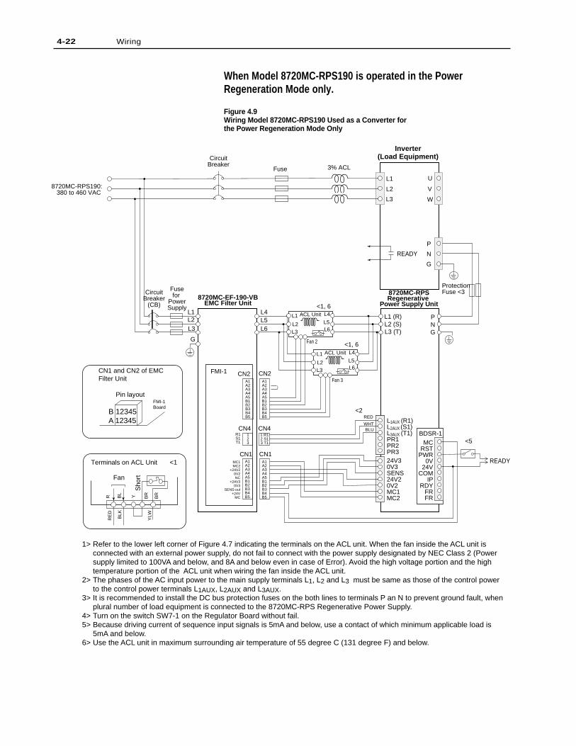
When Model 8720MC-RPS190 is operated in the PowerRegeneration Mode only.
Figure 4.9Wiring Model 8720MC-RPS190 Used as a Converter forthe Power Regeneration Mode Only
4-22 Wiring
CN2 CN2
CN4123
CN4
CN1A1A2A3A4A5B1B2B3B4B5
MC1MC2
+24V20V2NC
+24V30V3
SENS-out+24V
MC
L1
L1
L4L5L6
L2
L2
L3
L3
L1 (R)L2 (S)L3 (T)
PNG
L1AUX (R1)L2AUX (S1)L3AUX (T1)PR1PR2PR3
ACL Unit
24V30V3SENS24V20V2MC1MC2
MCRST
PWR0V
24VCOM
IPRDY
FRFR
RED
1 R12 S13 T1
WHTBLU
BDSR-1
CN1
G
8720MC-RPS190: 380 to 460 VAC
L4
L5L6
L1
L2L3
8720MC-EF-190-VBEMC Filter Unit
8720MC-RPSRegenerative
Power Supply Unit
Inverter(Load Equipment)
3% ACL
ProtectionFuse <3
Fuse
CircuitBreaker
P
N
G
U
V
W
Fusefor
PowerSupply
CircuitBreaker
(CB)
A1A2A3A4A5B1B2B3B4B5
A1A2A3A4A5B1B2B3B4B5
A1A2A3A4A5B1B2B3B4B5
R1S1T1
Fan 2
Fan 3
ACL Unit L4
L5L6
L1
L2L3
<5
<2
<1, 6
<1, 6
READY
FMI-1
Fan
YLWBLK
BL
BR
BR
RE
DR Y
Sho
rt
Terminals on ACL Unit
CN1 and CN2 of EMCFilter Unit
B 12345A 12345
Pin layoutFMI-1Board
<1 READY
1> Refer to the lower left corner of Figure 4.7 indicating the terminals on the ACL unit. When the fan inside the ACL unit is connected with an external power supply, do not fail to connect with the power supply designated by NEC Class 2 (Power supply limited to 100VA and below, and 8A and below even in case of Error). Avoid the high voltage portion and the high temperature portion of the ACL unit when wiring the fan inside the ACL unit.
2> The phases of the AC input power to the main supply terminals L1, L2 and L3 must be same as those of the control power to the control power terminals L1AUX, L2AUX and L3AUX.
3> It is recommended to install the DC bus protection fuses on the both lines to terminals P an N to prevent ground fault, when plural number of load equipment is connected to the 8720MC-RPS Regenerative Power Supply.
4> Turn on the switch SW7-1 on the Regulator Board without fail.5> Because driving current of sequence input signals is 5mA and below, use a contact of which minimum applicable load is
5mA and below.6> Use the ACL unit in maximum surrounding air temperature of 55 degree C (131 degree F) and below.

4-23Wiring
It is possible to select the 8720MC-RPS units depending on theregenerative power when only regenerated power of the unitintegrating converter and inverter is used. In this case, however,the following cautions must be observed. Figure 4.4 shows wiringof the 8720MC-RPS027 or 8720MC-RPS065 unit used as aconverter for the power regeneration mode only.
• Rating of regenerative power of the 8720MC-RPS is less thanrated power both in the instantaneous rating and continuousrating.
• When rectifier portion of inverter is composed of thyristor, CRsnubber circuit between anode and cathode of thyristor maybecome overloaded. Therefore, treating time for regenerativepower must be within 5 seconds for 3 minutes. Because thecurrent "ICR" flowing through CR snubber circuit in the powerregeneration mode is represented by the following formula,verify the specifications of CR snubber circuit.
• Do not fail to connect ACL unit of 3% impedance towardinverter rating with the AC input line of inverter. Without ACLunit, excessive circulating current will flow between the8720MC-RPS units.
• Even during the power running, current will be supplied fromthe 8720MC-RPS unit to DC bus proportionally to the impedanceratio of both reactors at the 8720MC-RPS unit and inverter. Thiscurrent must not exceed the rating of the 8720MC-RPS unit.
• Set the parameter of the FWD Current Limit (U.001) to zero (0).
• Set the parameter of the Discharging Function Enable (F.017) tozero (OFF).
• Set the DC bus voltage to start power regeneration to theparameter of the DC Bus Voltage Reference (U.000).
• Open all the terminals PR1, PR2 and PR3 for connectingprecharge/discharge resistor. Because these terminals are open,the unit does not perform precharge/discharge operations.Precharge/discharge must be performed on inverter side.
• Do not fail to enter the READY signal of inverter to (PWR).
ICR[A] = (8 0.03 x R [Ω]) x C [µF]
4-24 Wiring
Capacity of built-in Capacitor
Built-in Resistor (Resistance Value/Wattage)
External Resistor (Minimum Resistance Value),Connect to PR1 and PR2
External Circuit (Minimum Resistance Value),Refer to figure 4.10
8720MC-RPS190 Unit
7600µF
25000µF(10 ohm/400W)
165000µF(10 ohm)
495000µF(1.5 ohm)
External resistor case
Most applications are successfully integrated using the internalprecharge resistor provided in the 8720MC-RPS RegenerativePower Supply. For instances where there is a large amount of loadcapacitance, caused by connecting several 8720MC drives to asingle 8720MC-RPS Regenerative Power Supply, an externalprecharge resistor may be required. To determine the totalcapacitance C[F] add the capacitance for the applicable RPS190unit, as determined from row 1 of Table 4.5, to the sum of the drivecapacitance as determined by the drive specifications in Chapter 2of the 8720MC-RPS User Manual, Publication 8720-UM-001-B-US-P FEB 2001. In the case of the RPS190 if the total capacitanceis above 25,000µf, but less than 165,000µf an external prechargeresistor connected to PR1 and PR2 is required. Table 4.8 providesthe minimum resistance value for the external resistor od 10 ohms.The wattage is determined by the equation presented above.Connect the external precharge resistor to terminals PR1 and PR2
When Model 8720MC-RPS190 is adapted to Capacitors havinglarge capacity
8720MC-RPS190 unit charges to capacitors with a single phase,full-wave rectification circuit through the built-in precharge/discharge resistor. When the load capacitors have largecapacitance, it takes more time for charging, and the wattage of theinternal resistor becomes insufficient. When the load capacitance islarge, disable the built-in precharge/discharge resistor and connectan external resistor or external circuit for precharging/discharging(Note that minimum precharging/discharging cycle is 3 minutes).
Calculate a rated wattage of the external precharge/dischargeresistor to be connected to the outside in accordance with thefollowing formula depending on the total capacitance of all thecapacitors including the built-in capacitor.
Rated wattage [W] = 17000 x C[F]But, serge resistivity of J[J] = 28000 x C[F] must be provided.
When an external precharge/discharge resistor is connected, changethe set value of the following parameters, if necessary.
• Precharge/Discharge Time (F.014)• Wattage of Precharge/Discharge Resistor (F.015)
Table 4.8Maximum Applicable Capacitance of Capacitor and Minimum Resistance Value
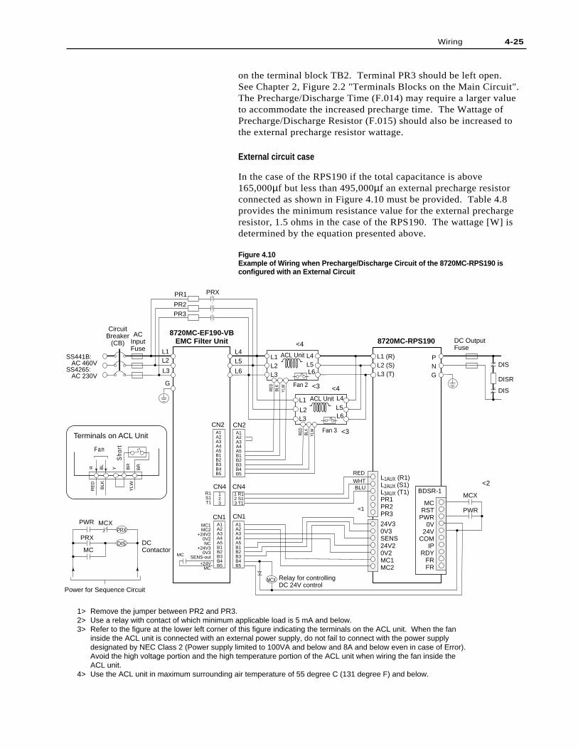
4-25Wiring
on the terminal block TB2. Terminal PR3 should be left open.See Chapter 2, Figure 2.2 "Terminals Blocks on the Main Circuit".The Precharge/Discharge Time (F.014) may require a larger valueto accommodate the increased precharge time. The Wattage ofPrecharge/Discharge Resistor (F.015) should also be increased tothe external precharge resistor wattage.
External circuit case
In the case of the RPS190 if the total capacitance is above165,000µf but less than 495,000µf an external precharge resistorconnected as shown in Figure 4.10 must be provided. Table 4.8provides the minimum resistance value for the external prechargeresistor, 1.5 ohms in the case of the RPS190. The wattage [W] isdetermined by the equation presented above.
Figure 4.10Example of Wiring when Precharge/Discharge Circuit of the 8720MC-RPS190 isconfigured with an External Circuit
CN2 CN2
CN4123
CN4
CN1MC1MC2
+24V20V2NC
+24V30V3
SENS-out
L1
PR3
PR2
PR1 PRX
MC
PRX
PWR MCX
L4
L5
L6
L2
L3
L1 (R)L2 (S)L3 (T)
PNG
DISR
DIS
PWR
MCX
Relay for controlling DC 24V control
DIS
L1AUX (R1)L2AUX (S1)L3AUX (T1)PR1PR2PR3
ACL Unit
24V30V3SENS24V20V2MC1MC2
MCRST
PWR0V
24VCOM
IPRDY
FRFR
RED
1 R12 S13 T1
WHTBLU BDSR-1
CN1
G
SS441B: AC 460VSS4265: AC 230V
L4
L5L6
L1L2L3
L4L5L6
L1
L2L3
<1
8720MC-EF190-VBEMC Filter Unit 8720MC-RPS190
YLWBLK
RE
DR B
L
Y BR
BR
CircuitBreaker
(CB)
A1A2A3A4A5B1B2B3B4B5
A1A2A3A4A5B1B2B3B4B5
A1A2A3A4A5B1B2B3B4B5
A1A2A3A4A5B1B2B3B4B5
R1S1T1
Fan 3
Fan 2
RED
BLK
YLW
YLW
RED
BLK
Sho
rt
Terminals on ACL Unit
Fan
DC Output Fuse
ACL Unit
ACInputFuse
MCX
PRX
DIS
+24VMC
MC
Power for Sequence Circuit
DCContactor
1> Remove the jumper between PR2 and PR3. 2> Use a relay with contact of which minimum applicable load is 5 mA and below.3> Refer to the figure at the lower left corner of this figure indicating the terminals on the ACL unit. When the fan
inside the ACL unit is connected with an external power supply, do not fail to connect with the power supply designated by NEC Class 2 (Power supply limited to 100VA and below and 8A and below even in case of Error).Avoid the high voltage portion and the high temperature portion of the ACL unit when wiring the fan inside the ACL unit.
4> Use the ACL unit in maximum surrounding air temperature of 55 degree C (131 degree F) and below.
<4
<3
<3
<2
<4
If a totally external resistor network is used as shown in figure4.10, the calculated wattage, [W] = 17,000 x C farads, is divided inhalf to size the precharge and discharge resistors.Parameter F.015 should be set to the sum of the wattage for bothresistors.
Installing Circuit Breaker - 8720MC-RPS190
To protect AC input power, install a circuit breaker withsupplemental contact (CB) in the AC input power line. Refer toFigures 4.6 to 4.8 for wiring. The rated ampacities of the circuitbreakers are as follows:
For Model 8720MC-RPS190BM and 8720MC-RPS190BS units:350 Amps
The following are the recommended circuit breakers withsupplemental contact.
For Model 8720MC-RPS190BM and 8720MC-RPS190BS units:
Fuji Electric - BU-KSB3350LWWestinghouse - KDB3350or equivalent
Because supplemental contact of this circuit breaker does notconform with load of 5mA, relay with less than 5mA should beused for connection when a supplemental contact is connected withsequence input PWR.
Be sure to provide required quantity of circuit breakers withsupplemental contact (CB) for all units connected in parallel (seeFigures 4.6 and 4.7).
Installing ACL Unit (Reactor Assembly) - 8720MC-RPS190
ATTENTION: During operation of the 8720MC-RPSRegenerative Power Supply, the reactor is at a hightemperature. Do not touch the reactor duringoperation or immediately after the unit has beenturned OFF. Failure to observe this precaution couldresult in bodily injury.
ATTENTION: During operation of the 8720MC-RPSRegenerative Power Supply, the reactor operates at ahigh temperature. Install the reactor in a locationwhere high temperature does not present a problem.
The 8720MC-RPS Regenerative Power Supply boosts up andcontrols the DC bus voltage, by utilizing the magneticcharacteristics of reactor. Therefore, reactors are required for the8720MC-RPS Regenerative Power Supply.
Install a single-phase type reactor to each of L1-phase, L2-phase andL3-phase. Do not use three-phase AC reactors, since this will causeunwanted coupling between the phases.
!
4-26 Wiring
!
4-27Wiring
The following inductance of the reactor must be maintained in ahigh frequency as 10 to 20 kHz. Note that use of a reactor forcommercial power supply may not maintain the requiredinductance, resulting in increased heat generation or saturation dueto iron loss.
When multiple units are connected in parallel, a current unbalancebetween the units is produced due to vibration of reactorinductance. To make the current difference between the connectedunits as small as possible, use reactors having a vibration of nomore than +/-2.5%.
The following are the designated reactors. These reactors areintegrated for three phases consisting of three single phasereactors. Depending on the motor capacity, single unit of thedesignated reactor is used or two units of reactors connected inparallel are used as shown below. When selected reactors areinstalled, set their capacity to the parameter F.013.
One (1) Model 8720MC-LR10-100B (800 micro-henry):For Model 8720MC-RPS190BM and 8720MC-RPS190BS thatare used at 100 Amps or less (capacity of applicable motor is 65kW or less)
Two (2) Model 8720MC-LR10-100B (800 micro-henry)connected in parallel:For Model 8720MC-RPS190BM and 8720MC-RPS190BS thatare used at 190 Amps or less (capacity of applicable motor is125 kW or less)
Cooling fan and thermoswitch are mounted on the ACL unit. Thethermo switch opens at about 150 degree C (302 degree F) andproduces a reactor fan fault signal.
The reactor should operate in an ambient temperature of 50 degreeC (122 degree F) or lower. If it is not avoidable to use a reactorabove 50 degree C (122 degree F), decrease current 1% for every 1degree C above 50 degree C.
Select temperature rating of 105 degree C (221 degree F) or higherfor the wire to connect Model 8720MC-LR10-100B reactors.
Installing Fuses - 8720MC-RPS190
Install a fuse on the AC incoming line. The following is therecommended fuse for the single unit.
FERRAZ SHAWMUT or equivalent (Class J Fuse)
Rated current of the fuse for Model 8720MC-RPS190 is 350Amps.
Also, as a measure against ground fault, install a fuse to protect theDC bus. The recommended fuses are as follows:
For Model 8720MC-RPS190BM and 8720MC-RPS190BSunits: FERRAZ SHAWMUT, A130URD71LLI0350
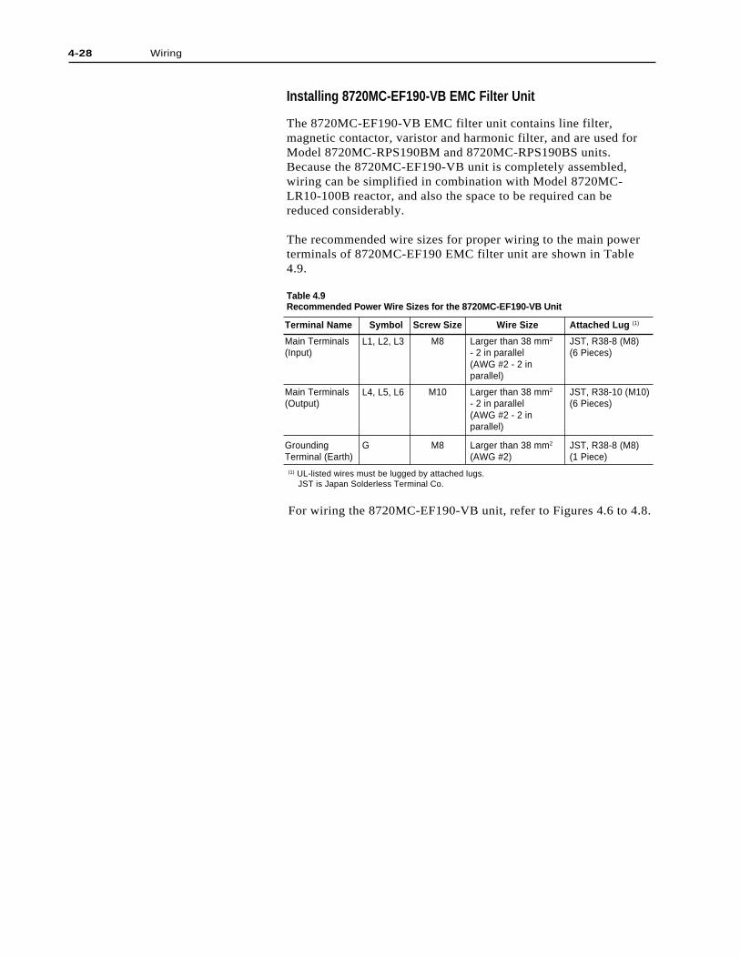
4-28 Wiring
Terminal Name
Main Terminals(Input)
Main Terminals(Output)
GroundingTerminal (Earth)
Symbol
L1, L2, L3
L4, L5, L6
G
Screw Size
M8
M10
M8
Wire Size
Larger than 38 mm2
- 2 in parallel(AWG #2 - 2 inparallel)
Larger than 38 mm2
- 2 in parallel(AWG #2 - 2 inparallel)
Larger than 38 mm2
(AWG #2)
Attached Lug (1)
JST, R38-8 (M8)(6 Pieces)
JST, R38-10 (M10)(6 Pieces)
JST, R38-8 (M8)(1 Piece)
(1) UL-listed wires must be lugged by attached lugs. JST is Japan Solderless Terminal Co.
For wiring the 8720MC-EF190-VB unit, refer to Figures 4.6 to 4.8.
Installing 8720MC-EF190-VB EMC Filter Unit
The 8720MC-EF190-VB EMC filter unit contains line filter,magnetic contactor, varistor and harmonic filter, and are used forModel 8720MC-RPS190BM and 8720MC-RPS190BS units.Because the 8720MC-EF190-VB unit is completely assembled,wiring can be simplified in combination with Model 8720MC-LR10-100B reactor, and also the space to be required can bereduced considerably.
The recommended wire sizes for proper wiring to the main powerterminals of 8720MC-EF190 EMC filter unit are shown in Table4.9.
Table 4.9Recommended Power Wire Sizes for the 8720MC-EF190-VB Unit
4-29Wiring
Installing DC Bus PowerOutput Wiring - All RPSunits
ATTENTION: When connecting the DC bus to pluralnumber of external load equipment, the user isresponsible for installing fuses to protect the DC busfrom shorting, if no fuse is provided in the loadequipment. Failure to observe this precaution couldresult in damage to, or destruction of, the equipment
ATTENTION: Exercise extreme caution for polarityof wiring when wiring DC bus. Failure to observethis precaution could result in damage to, ordestruction of, the 8720MC-RPS Regenerative PowerSupply and the connected load equipment.
The DC bus output terminals on the main power terminal block(TB1) or the DC bus terminal bars of the 8720MC-RPSRegenerative Power Supply are used for connecting to loadequipment such as inverter. Use the recommended wire size shownin Tables 4.1 to 4.3 for wiring between the 8720MC-RPSRegenerative Power Supply and the load equipment. Connect theterminal P on the main power terminal block (TB1) or the terminalbar P of the 8720MC-RPS Regenerative Power Supply to thepositive (plus) DC bus terminal of the load equipment, and theterminal N on the terminal block TB1 or the terminal bar N to thenegative (minus) DC bus terminal of the load equipment. Do notconnect the positive (plus) side with the wiring of the negative(minus) side. Such miswiring will damage the 8720MC-RPSRegenerative Power Supply and the connected load equipment.
When multiple drives are connected to the 8720MC-RPSRegenerative Power Supply, always install input fuses before eachdrive to protect the wiring and the drive. Select adequate fuse(s)for the drives.
Connect an adequate equipment grounding conductor to groundterminal of load equipment, remote control station (if used), inputtransformer (if used), and ground terminal of the 8720MC-RPSRegenerative Power Supply. Run earth conductor to earth groundafter confirming that the conductors are unbroken.
This system is operated by switching DC bus line from + (plus) busvoltage to - (minus) bus voltage viewing from the ground for thepurpose of controlling. For this reason, plus and minus voltages arealways added on a circuit if equipment has a circuit between the busline of equipment to be connected and the ground (earth). Even ifthere exists no direct circuit between the bus line and the ground,pulse current will flow through the stray capacity of the equipmentby bus voltage switching. When 8720MC-RPS and equipment to beconnected to 8720MC-RPS are not securely grounded, this currentwill flow through the circuit and may cause malfunction of them. Ifgrounding is not made properly, it will cause the malfunction of theother system on the same line.
Install an insulating transformer to the input line of the 8720MC-RPS if unbalanced current flows and earth leakage breakermalfunctions due to the power supply conditions.
For grounding, use the wire size of grounding terminal as shown inTable 4.1 through 4.3.
Grounding the 8720MC-RPSRegenerative Power Supply
!
!

4-30 Wiring
Wiring To Comply with EMC To declare the conformity with the requirements for CE Mark,8720MC-RPS Regenerative Power Supply must comply with bothEMC directive and low voltage directive. This section describesnotes on wiring to comply with EMC directive.
Important: 8720MC-RPS Regenerative Power Supply itself is notsubject to Machine directive. When 8720MC-RPS RegenerativePower Supply is combined with other equipment, control cabinetand machine, it is needed to declare the compliance with Machinedirective. Noise level will vary depending on the installation andwiring of 8720MC-RPS Regenerative Power Supply, otherequipment and control cabinet. It has been already confirmed that8720MC-RPS Regenerative Power Supply complies with EMCstandards only when 8720MC-RPS Regenerative Power Supply iscomposed of the component parts designated by Reliance Electric.In order for users to declare the conformity with the requirementsfor CE Mark, do not fail to confirm that the unit complies withEMC standards on the final conditions after completion ofinstallation and wiring.
The following show with which EMC standards each of the8720MC-RPS Regenerative Power Supply complies.
8720MC-RPS027 EN61800-3:1996 includingAmendment A11:2000
8720MC-RPS065 EN55011:1991 Group 1, Class A, andAmendment A1:1999EN50082-2:1995
8720MC-RPS190 EN61800-3:1996 includingAmendment A11:2000
Wiring must be made taking into consideration of the followingcountermeasures since there is the possibility that input and outputlines of the 8720MC-RPS Regenerative Power Supply may yieldstrong noise.
1. Use a control cabinet made of metal for installing the 8720MC-RPS Regenerative Power Supply (It has been confirmed thatthis unit complies with EMC standards when installed inside thecontrol cabinet).
2. Install a line filter designated by Reliance Electric to the powerinput line of the 8720MC-RPS units. Wiring to the line filtermust be as short as possible.
3. Because current will leak to the earth when a line filter isinstalled, connection to the earth must be secured. Due toleaked current, the earth leakage breaker may malfunction.Select a proper breaker complying with leaked current (Ratedcurrent 100 to 500mA and operating time within 0.1 to 2seconds).
4. The control cabinet must be securely grounded. Wiring to betaken into grounding terminal of the control cabinet must be asthick and short as possible.

5. The input and output line of the 8720MC-RPS units must beseparated from the output line of the inverter unit as far aspossible.
6. Wiring of the control signal must be terminated within thecontrol cabinet. Should the control cable be needed to extendout of the control cabinet, it is recommended to use shieldedcables. When ferrite cores are used, install them possibly to theside of the 8720MC-RPS units. The following are the ferritecores for the control cables recommended.
ZCAT2032-0930 (Inside diameter 9 +/- 1mm) : TDK
ZCAT2035-1330 (Inside diameter 13 +/- 1mm) : TDK
7. For notes on wiring to the other equipment and motors to beconnected with the 8720MC-RPS, refer to the manuals ofrelevant equipment.
4-31Wiring
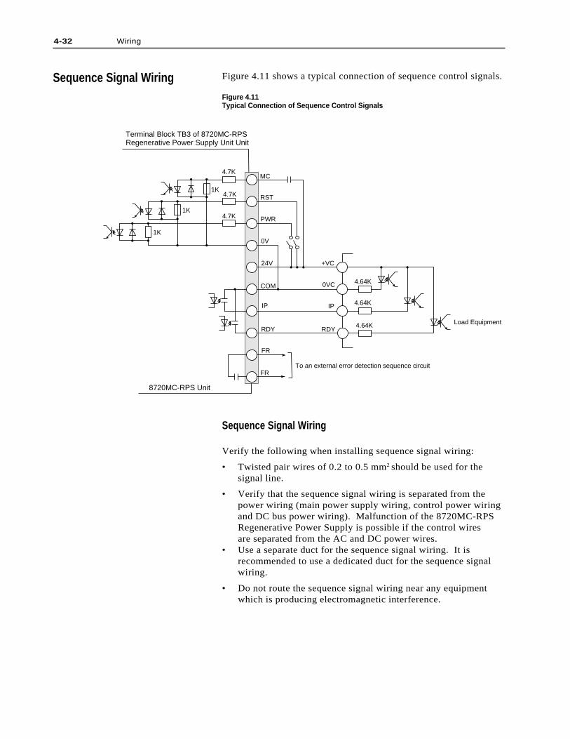
4-32 Wiring
Sequence Signal Wiring
Sequence Signal Wiring
Verify the following when installing sequence signal wiring:
• Twisted pair wires of 0.2 to 0.5 mm2 should be used for thesignal line.
• Verify that the sequence signal wiring is separated from thepower wiring (main power supply wiring, control power wiringand DC bus power wiring). Malfunction of the 8720MC-RPSRegenerative Power Supply is possible if the control wiresare separated from the AC and DC power wires.
• Use a separate duct for the sequence signal wiring. It isrecommended to use a dedicated duct for the sequence signalwiring.
• Do not route the sequence signal wiring near any equipmentwhich is producing electromagnetic interference.
Figure 4.11 shows a typical connection of sequence control signals.
Figure 4.11Typical Connection of Sequence Control Signals
MC
1K
1K
1K4.7K
4.7K
4.7K
RST
PWR
0V
24V
COM
IP IP
RDY RDY
FR
FR
4.64K
4.64K
4.64K Load Equipment
Terminal Block TB3 of 8720MC-RPS Regenerative Power Supply Unit Unit
8720MC-RPS Unit
+VC
0VC
To an external error detection sequence circuit
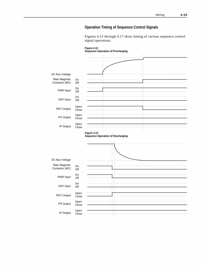
Figure 4.13Sequence Operation of Discharging
Operation Timing of Sequence Control Signals
Figures 4.12 through 4.17 show timing of various sequence controlsignal operations.
Figure 4.12Sequence Operation of Precharging
OnOff
OnOff
OnOff
OpenClose
OpenClose
OpenClose
RST Input
RDY Output
FR Output
IP Output
DC Bus Voltage
Main MagneticContactor (MC)
PWR Input
OnOff
OnOff
OnOff
OpenClose
OpenClose
OpenClose
DC Bus Voltage
Main MagneticContactor (MC)
PWR Input
RST Input
RDY Output
FR Output
IP Output
4-33Wiring
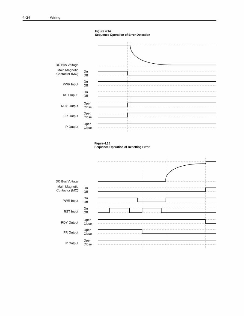
4-34 Wiring
OnOff
OnOff
OnOff
OpenClose
OpenClose
OpenClose
DC Bus Voltage
PWR Input
RST Input
RDY Output
FR Output
IP Output
Main MagneticContactor (MC)
OnOff
OnOff
OnOff
OpenClose
OpenClose
OpenClose
DC Bus Voltage
PWR Input
RST Input
RDY Output
FR Output
IP Output
Main MagneticContactor (MC)
Figure 4.14Sequence Operation of Error Detection
Figure 4.15Sequence Operation of Resetting Error
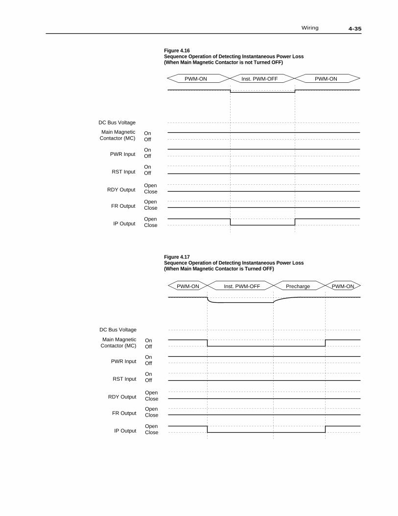
Figure 4.16Sequence Operation of Detecting Instantaneous Power Loss(When Main Magnetic Contactor is not Turned OFF)
Figure 4.17Sequence Operation of Detecting Instantaneous Power Loss(When Main Magnetic Contactor is Turned OFF)
OnOff
OnOff
OnOff
OpenClose
OpenClose
OpenClose
DC Bus Voltage
PWR Input
RST Input
RDY Output
FR Output
IP Output
PWM-ON PWM-ONInst. PWM-OFF
Main MagneticContactor (MC)
OnOff
OnOff
OnOff
OpenClose
OpenClose
OpenClose
DC Bus Voltage
PWR Input
RST Input
RDY Output
FR Output
IP Output
PWM-ON PWM-ONInst. PWM-OFF Precharge
Main MagneticContactor (MC)
4-35Wiring
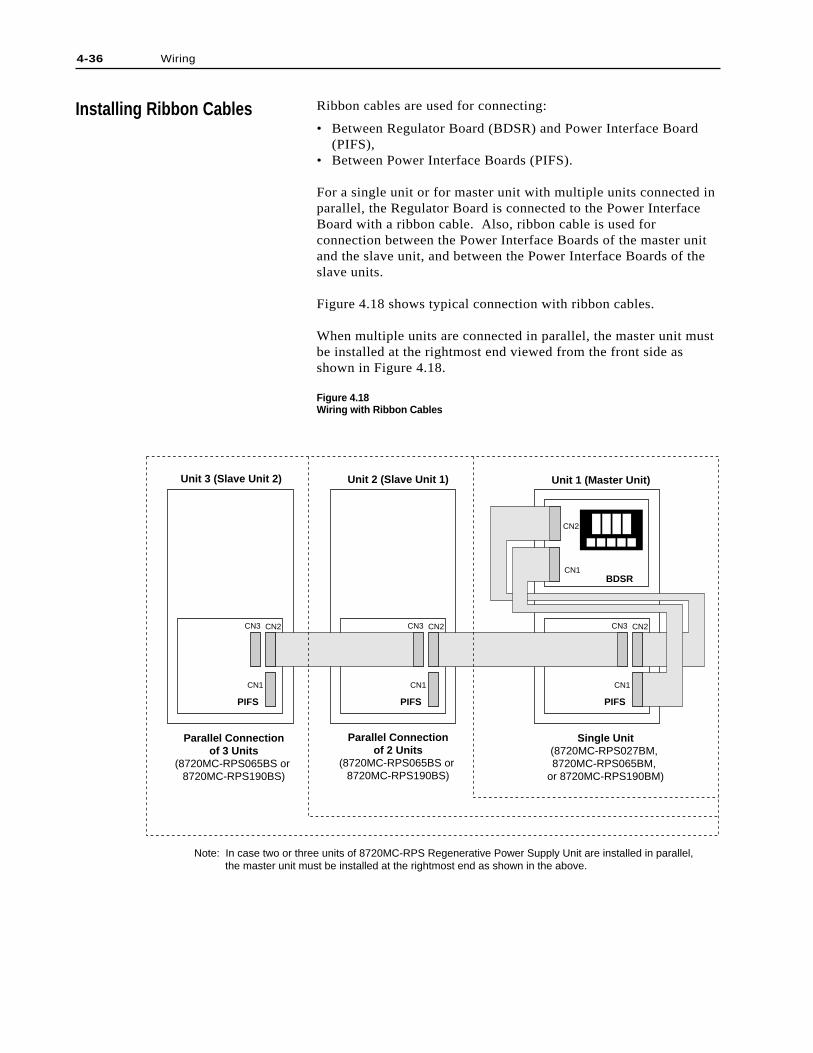
4-36 Wiring
Installing Ribbon Cables Ribbon cables are used for connecting:
• Between Regulator Board (BDSR) and Power Interface Board(PIFS),
• Between Power Interface Boards (PIFS).
For a single unit or for master unit with multiple units connected inparallel, the Regulator Board is connected to the Power InterfaceBoard with a ribbon cable. Also, ribbon cable is used forconnection between the Power Interface Boards of the master unitand the slave unit, and between the Power Interface Boards of theslave units.
Figure 4.18 shows typical connection with ribbon cables.
When multiple units are connected in parallel, the master unit mustbe installed at the rightmost end viewed from the front side asshown in Figure 4.18.
Figure 4.18Wiring with Ribbon Cables
BDSR
PIFS
CN1
CN2
CN1
CN2CN3
Unit 1 (Master Unit)Unit 2 (Slave Unit 1)Unit 3 (Slave Unit 2)
Single Unit(8720MC-RPS027BM, 8720MC-RPS065BM,
or 8720MC-RPS190BM)
Parallel Connectionof 2 Units
(8720MC-RPS065BS or 8720MC-RPS190BS)
Parallel Connectionof 3 Units
(8720MC-RPS065BS or 8720MC-RPS190BS)
PIFS
CN1
CN2CN3
PIFS
CN1
CN2CN3
Note: In case two or three units of 8720MC-RPS Regenerative Power Supply Unit are installed in parallel, the master unit must be installed at the rightmost end as shown in the above.
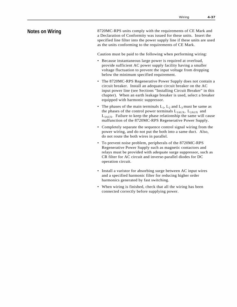
Notes on Wiring 8720MC-RPS units comply with the requirements of CE Mark anda Declaration of Conformity was issued for these units. Insert thespecified line filter into the power supply line if these units are usedas the units conforming to the requirements of CE Mark.
Caution must be paid to the following when performing wiring:
• Because instantaneous large power is required at overload,provide sufficient AC power supply facility having a smallervoltage fluctuation to prevent the input voltage from droppingbelow the minimum specified requirement.
• The 8720MC-RPS Regenerative Power Supply does not contain acircuit breaker. Install an adequate circuit breaker on the ACinput power line (see Sections "Installing Circuit Breaker" in thischapter). When an earth leakage breaker is used, select a breakerequipped with harmonic suppressor.
• The phases of the main terminals L1, L2 and L3 must be same asthe phases of the control power terminals L1AUX, L2AUX andL3AUX. Failure to keep the phase relationship the same will causemalfunction of the 8720MC-RPS Regenerative Power Supply.
• Completely separate the sequence control signal wiring from thepower wiring, and do not put the both into a same duct. Also,do not route the both wires in parallel.
• To prevent noise problem, peripherals of the 8720MC-RPSRegenerative Power Supply such as magnetic contactors andrelays must be provided with adequate surge suppressor, such asCR filter for AC circuit and inverse-parallel diodes for DCoperation circuit.
• Install a varistor for absorbing surge between AC input wiresand a specified harmonic filter for reducing higher orderharmonics generated by fast switching.
• When wiring is finished, check that all the wiring has beenconnected correctly before supplying power.
4-37Wiring

4-38 Wiring
End of Chapter
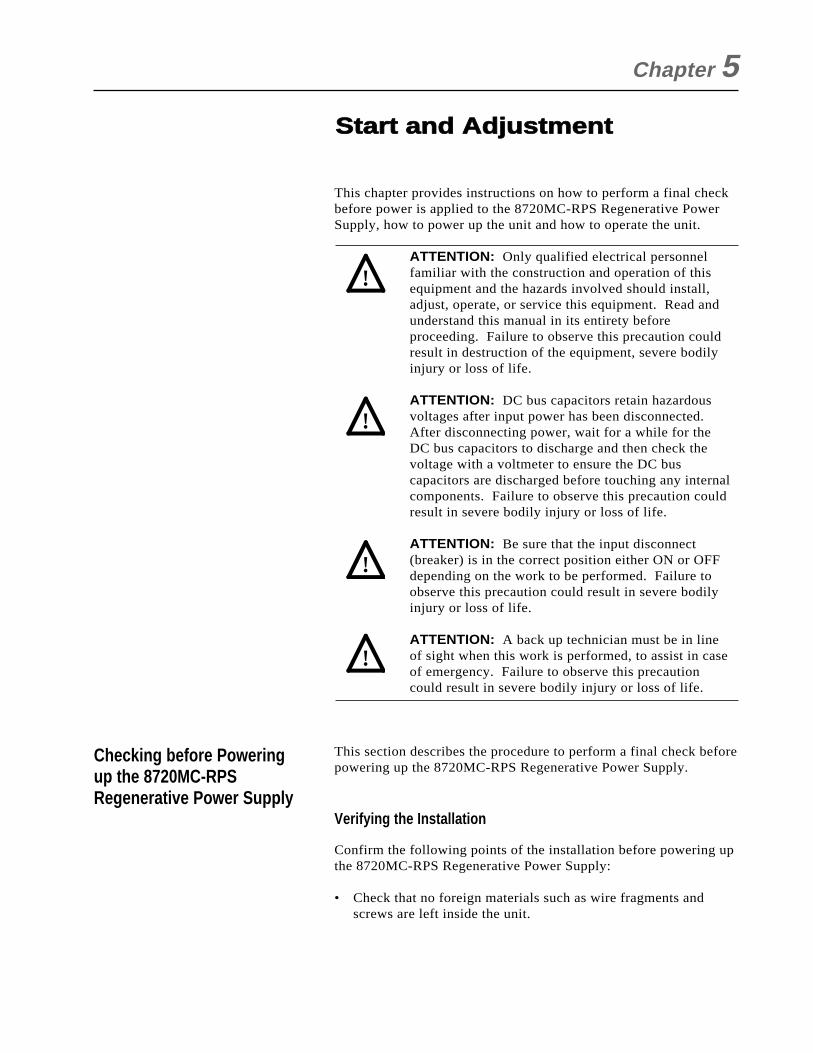
This chapter provides instructions on how to perform a final checkbefore power is applied to the 8720MC-RPS Regenerative PowerSupply, how to power up the unit and how to operate the unit.
ATTENTION: Only qualified electrical personnelfamiliar with the construction and operation of thisequipment and the hazards involved should install,adjust, operate, or service this equipment. Read andunderstand this manual in its entirety beforeproceeding. Failure to observe this precaution couldresult in destruction of the equipment, severe bodilyinjury or loss of life.
ATTENTION: DC bus capacitors retain hazardousvoltages after input power has been disconnected.After disconnecting power, wait for a while for theDC bus capacitors to discharge and then check thevoltage with a voltmeter to ensure the DC buscapacitors are discharged before touching any internalcomponents. Failure to observe this precaution couldresult in severe bodily injury or loss of life.
ATTENTION: Be sure that the input disconnect(breaker) is in the correct position either ON or OFFdepending on the work to be performed. Failure toobserve this precaution could result in severe bodilyinjury or loss of life.
ATTENTION: A back up technician must be in lineof sight when this work is performed, to assist in caseof emergency. Failure to observe this precautioncould result in severe bodily injury or loss of life.
This section describes the procedure to perform a final check beforepowering up the 8720MC-RPS Regenerative Power Supply.
Verifying the Installation
Confirm the following points of the installation before powering upthe 8720MC-RPS Regenerative Power Supply:
• Check that no foreign materials such as wire fragments andscrews are left inside the unit.
Chapter 5
Checking before Poweringup the 8720MC-RPSRegenerative Power Supply
Start and Adjustment
!
!
!
!
• Verify that there is no debris such as metal shavings around theunit.
• Check that there is adequate clearance around the unit.
Verifying the Rating of the 8720MC-RPS Regenerative PowerSupply
Before powering up the 8720MC-RPS Regenerative Power Supply,check the following:
• Check the unit's nameplate and confirm that the installed8720MC-RPS Regenerative Power Supply has an enough ratingfor the load.
• Check that the incoming power is rated correctly for the ratingof the 8720MC-RPS Regenerative Power Supply.
• Check that the disconnect (breaker) and the fuses provided forthe branch circuit protection are rated correctly.
• Check that the AC reactor is rated correctly.
Verifying Wiring
Check the following before powering up the 8720MC-RPSRegenerative Power Supply:
• Verify that the 8720MC-RPS Regenerative Power Supply wasinstalled rigidly.
• Check that there is no miswiring.
• Check that no terminals or connection are loose.
• Verify that there are no short circuits with regard to theterminals L1, L2, L3, P, N and G. Also verify that there are noground faults with regard to these terminals except terminal G.
• Check that the terminals L1AUX, L2AUX and L3AUX are notshorted.
• Verify that the electronic size is within the specification rangeand the wire is tightened correctly.
• Verify that the operations of the sequence control signals arenormal.
Use the following procedure to turn power to the 8720MC-RPSRegenerative Power Supply ON:
Step 1. Turn the RUN sequence signal OFF.
Step 2. Turn the input power breaker to the ON position.
Step 3. Apply power to the 8720MC-RPS Regenerative PowerSupply.
5-2 Start and Adjustment
Powering up the 8720MC-RPSRegenerative Power Supply

Start and Adjustment 5-3
Step 4. Verify that the unit powers up properly without incidentsuch as abnormal sound or nasty smell.
Step 5. Verify that there is no input power voltage drop or shortcircuit.
Step 6. Verify that the rating of the 8720MC-RPS RegenerativePower Supply matches the parameter setting of the UnitSelection (F.001).
For Step 6, more information will be given in the section"Operating the 8720MC-RPS Regenerative Power Supply" in thisChapter.
This section describes the following basic start-up and operationprocedure:
• Powering up
• Precharging
• Verifying the parameter of the Unit Selection
• Checking the DC bus voltage
• Changing the DC bus voltage reference value
• Discharging
• Disconnecting power
This start-up procedure describes how to set the minimum set ofparameters. Your application may require programming otherparameters in addition to those described in this start-upprocedure. Refer to Chapter 8 for description of all parameters toverify whether you need to program any additional parameters aswell.
In this manual, you will see references to parameters names and thenumbers that identify them for the 8720MC-RPS RegenerativePower Supply. This manual uses the same format that will beshown on the display to refer to parameters:
U.nnnF.nnn
where: nnn is a numberU designates User parametersF designates Factory parameters.
Operating the 8720MC-RPSRegenerative Power Supply
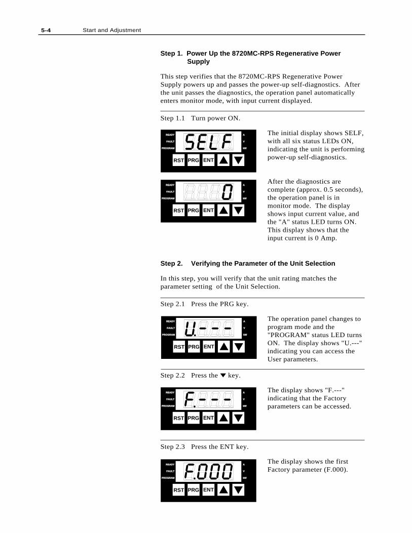
5-4 Start and Adjustment
Step 1. Power Up the 8720MC-RPS Regenerative Power Supply
This step verifies that the 8720MC-RPS Regenerative PowerSupply powers up and passes the power-up self-diagnostics. Afterthe unit passes the diagnostics, the operation panel automaticallyenters monitor mode, with input current displayed.
Step 1.1 Turn power ON.
The initial display shows SELF,with all six status LEDs ON,indicating the unit is performingpower-up self-diagnostics.
After the diagnostics arecomplete (approx. 0.5 seconds),the operation panel is inmonitor mode. The displayshows input current value, andthe "A" status LED turns ON.This display shows that theinput current is 0 Amp.
Step 2. Verifying the Parameter of the Unit Selection
In this step, you will verify that the unit rating matches theparameter setting of the Unit Selection.
Step 2.1 Press the PRG key.
The operation panel changes toprogram mode and the"PROGRAM" status LED turnsON. The display shows "U.---"indicating you can access theUser parameters.
Step 2.2 Press the key.
The display shows "F.---"indicating that the Factoryparameters can be accessed.
Step 2.3 Press the ENT key.
The display shows the firstFactory parameter (F.000).
RST PRG ENT
READYREADY
FAULTFAULT
PROGRAMPROGRAM kWkW
V
A
RST PRG ENT
READYREADY
FAULTFAULT
PROGRAMPROGRAM kWkW
V
A
RST PRG ENT
READYREADY
FAULTFAULT
PROGRAMPROGRAM kWkW
V
A
RST PRG ENT
READYREADY
FAULTFAULT
PROGRAMPROGRAM kWkW
V
A
RST PRG ENT
READYREADY
FAULTFAULT
PROGRAMPROGRAM kWkW
V
A
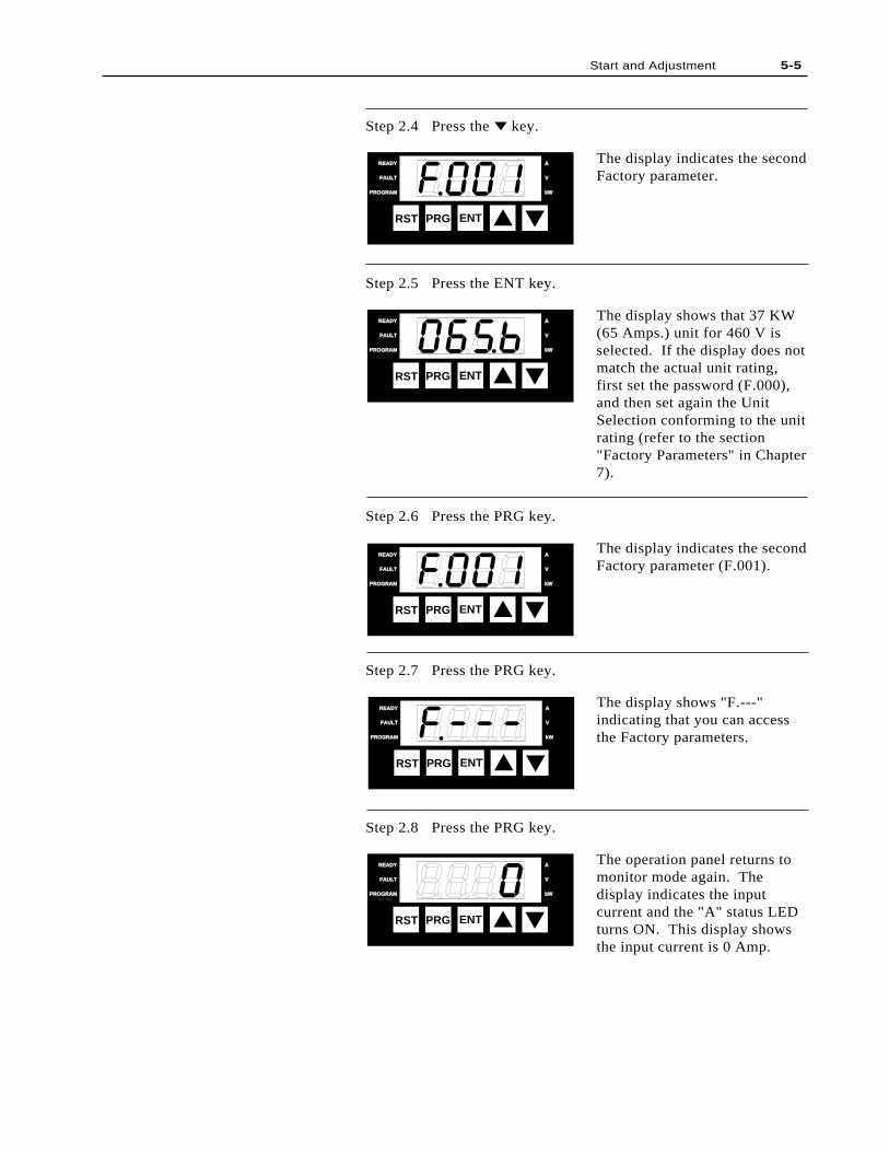
Step 2.4 Press the key.
The display indicates the secondFactory parameter.
Step 2.5 Press the ENT key.
The display shows that 37 KW(65 Amps.) unit for 460 V isselected. If the display does notmatch the actual unit rating,first set the password (F.000),and then set again the UnitSelection conforming to the unitrating (refer to the section"Factory Parameters" in Chapter7).
Step 2.6 Press the PRG key.
The display indicates the secondFactory parameter (F.001).
Step 2.7 Press the PRG key.
The display shows "F.---"indicating that you can accessthe Factory parameters.
Step 2.8 Press the PRG key.
The operation panel returns tomonitor mode again. Thedisplay indicates the inputcurrent and the "A" status LEDturns ON. This display showsthe input current is 0 Amp.
Start and Adjustment 5-5
RST PRG ENT
READYREADY
FAULTFAULT
PROGRAMPROGRAM kWkW
V
A
RST PRG ENT
READYREADY
FAULTFAULT
PROGRAMPROGRAM kWkW
V
A
RST PRG ENT
READYREADY
FAULTFAULT
PROGRAMPROGRAM kWkW
V
A
RST PRG ENT
READY
FAULT
PROGRAM kW
V
A
RST PRG ENT
READYREADY
FAULTFAULT
PROGRAMPROGRAM kWkW
V
A
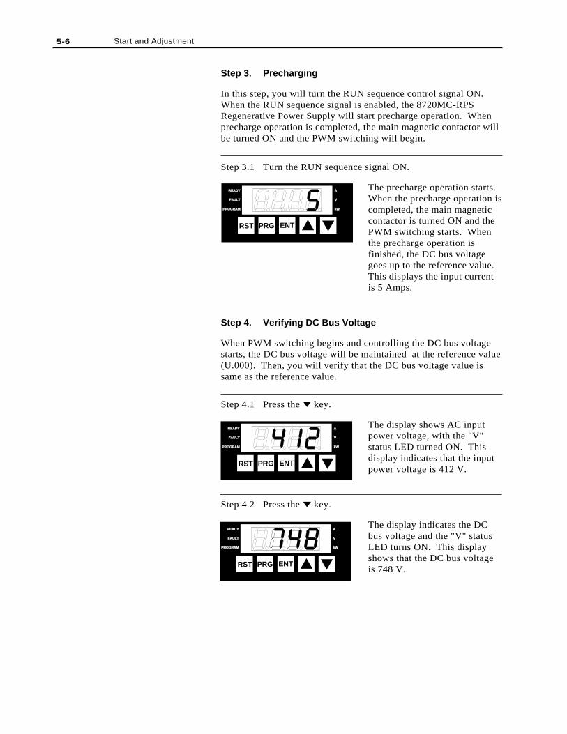
Step 3. Precharging
In this step, you will turn the RUN sequence control signal ON.When the RUN sequence signal is enabled, the 8720MC-RPSRegenerative Power Supply will start precharge operation. Whenprecharge operation is completed, the main magnetic contactor willbe turned ON and the PWM switching will begin.
Step 3.1 Turn the RUN sequence signal ON.
The precharge operation starts.When the precharge operation iscompleted, the main magneticcontactor is turned ON and thePWM switching starts. Whenthe precharge operation isfinished, the DC bus voltagegoes up to the reference value.This displays the input currentis 5 Amps.
Step 4. Verifying DC Bus Voltage
When PWM switching begins and controlling the DC bus voltagestarts, the DC bus voltage will be maintained at the reference value(U.000). Then, you will verify that the DC bus voltage value issame as the reference value.
Step 4.1 Press the key.
The display shows AC inputpower voltage, with the "V"status LED turned ON. Thisdisplay indicates that the inputpower voltage is 412 V.
Step 4.2 Press the key.
The display indicates the DCbus voltage and the "V" statusLED turns ON. This displayshows that the DC bus voltageis 748 V.
5-6 Start and Adjustment
RST PRG ENT
READYREADY
FAULTFAULT
PROGRAMPROGRAM kWkW
V
A
RST PRG ENT
READYREADY
FAULTFAULT
PROGRAMPROGRAM kWkW
V
A
RST PRG ENT
READYREADY
FAULTFAULT
PROGRAMPROGRAM kWkW
V
A
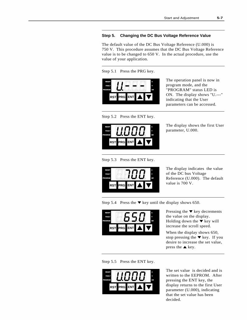
Step 5. Changing the DC Bus Voltage Reference Value
The default value of the DC Bus Voltage Reference (U.000) is750 V. This procedure assumes that the DC Bus Voltage Referencevalue is to be changed to 650 V. In the actual procedure, use thevalue of your application.
Step 5.1 Press the PRG key.
The operation panel is now inprogram mode, and the"PROGRAM" status LED isON. The display shows "U.---"indicating that the Userparameters can be accessed.
Step 5.2 Press the ENT key.
The display shows the first Userparameter, U.000.
Step 5.3 Press the ENT key.
The display indicates the valueof the DC bus VoltageReference (U.000). The defaultvalue is 700 V.
Step 5.4 Press the key until the display shows 650.
Pressing the key decrementsthe value on the display.Holding down the key willincrease the scroll speed.
When the display shows 650,stop pressing the key. If youdesire to increase the set value,press the key.
Step 5.5 Press the ENT key.
The set value is decided and iswritten to the EEPROM. Afterpressing the ENT key, thedisplay returns to the first Userparameter (U.000), indicatingthat the set value has beendecided.
Start and Adjustment 5-7
RST PRG ENT
READY
FAULT
PROGRAM kW
V
A
RST PRG ENT
READY
FAULT
PROGRAM kW
V
A
RST PRG ENT
READYREADY
FAULTFAULT
PROGRAMPROGRAM kWkW
V
A
RST PRG ENT
READYREADY
FAULTFAULT
PROGRAMPROGRAM kWkW
V
A
RST PRG ENT
READYREADY
FAULTFAULT
PROGRAMPROGRAM kWkW
V
A
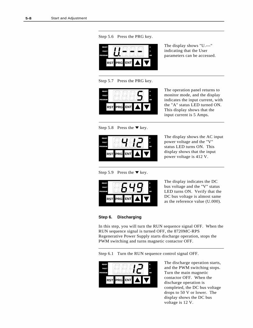
5-8 Start and Adjustment
Step 5.6 Press the PRG key.
The display shows "U.---"indicating that the Userparameters can be accessed.
Step 5.7 Press the PRG key.
The operation panel returns tomonitor mode, and the displayindicates the input current, withthe "A" status LED turned ON.This display shows that theinput current is 5 Amps.
Step 5.8 Press the key.
The display shows the AC inputpower voltage and the "V"status LED turns ON. Thisdisplay shows that the inputpower voltage is 412 V.
Step 5.9 Press the key.
The display indicates the DCbus voltage and the "V" statusLED turns ON. Verify that theDC bus voltage is almost sameas the reference value (U.000).
Step 6. Discharging
In this step, you will turn the RUN sequence signal OFF. When theRUN sequence signal is turned OFF, the 8720MC-RPSRegenerative Power Supply starts discharge operation, stops thePWM switching and turns magnetic contactor OFF.
Step 6.1 Turn the RUN sequence control signal OFF.
The discharge operation starts,and the PWM switching stops.Turn the main magneticcontactor OFF. When thedischarge operation iscompleted, the DC bus voltagedrops to 50 V or lower. Thedisplay shows the DC busvoltage is 12 V.
RST PRG ENT
READYREADY
FAULTFAULT
PROGRAMPROGRAM kWkW
V
A
RST PRG ENT
READYREADY
FAULTFAULT
PROGRAMPROGRAM kWkW
V
A
RST PRG ENT
READYREADY
FAULTFAULT
PROGRAMPROGRAM kWkW
V
A
RST PRG ENT
READYREADY
FAULTFAULT
PROGRAMPROGRAM kWkW
V
A
RST PRG ENT
READY
FAULT
PROGRAM kW
V
A
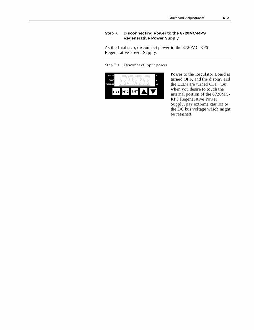
Start and Adjustment 5-9
Step 7. Disconnecting Power to the 8720MC-RPSRegenerative Power Supply
As the final step, disconnect power to the 8720MC-RPSRegenerative Power Supply.
Step 7.1 Disconnect input power.
Power to the Regulator Board isturned OFF, and the display andthe LEDs are turned OFF. Butwhen you desire to touch theinternal portion of the 8720MC-RPS Regenerative PowerSupply, pay extreme caution tothe DC bus voltage which mightbe retained.
RST PRG ENT
READY
FAULT
PROGRAM kW
V
A

5-10 Start and Adjustment
End of Chapter
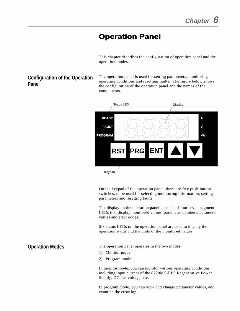
This chapter describes the configuration of operation panel and theoperation modes.
The operation panel is used for setting parameters, monitoringoperating conditions and resetting faults. The figure below showsthe configuration of the operation panel and the names of thecomponents.
On the keypad of the operation panel, there are five push-buttonswitches, to be used for selecting monitoring information, settingparameters and resetting faults.
The display on the operation panel consists of four seven-segmentLEDs that display monitored values, parameter numbers, parametervalues and error codes.
Six status LEDs on the operation panel are used to display theoperation status and the units of the monitored values.
The operation panel operates in the two modes:
1) Monitor mode
2) Program mode
In monitor mode, you can monitor various operating conditionsincluding input current of the 8720MC-RPS Regenerative PowerSupply, DC bus voltage, etc.
In program mode, you can view and change parameter values, andexamine the error log.
Chapter 6
Configuration of the OperationPanel
Operation Modes
Operation Panel
RST PRG ENT
READYREADY
FAULTFAULT
PROGRAMPROGRAM kW
V
A
Status LED Display
Keypad
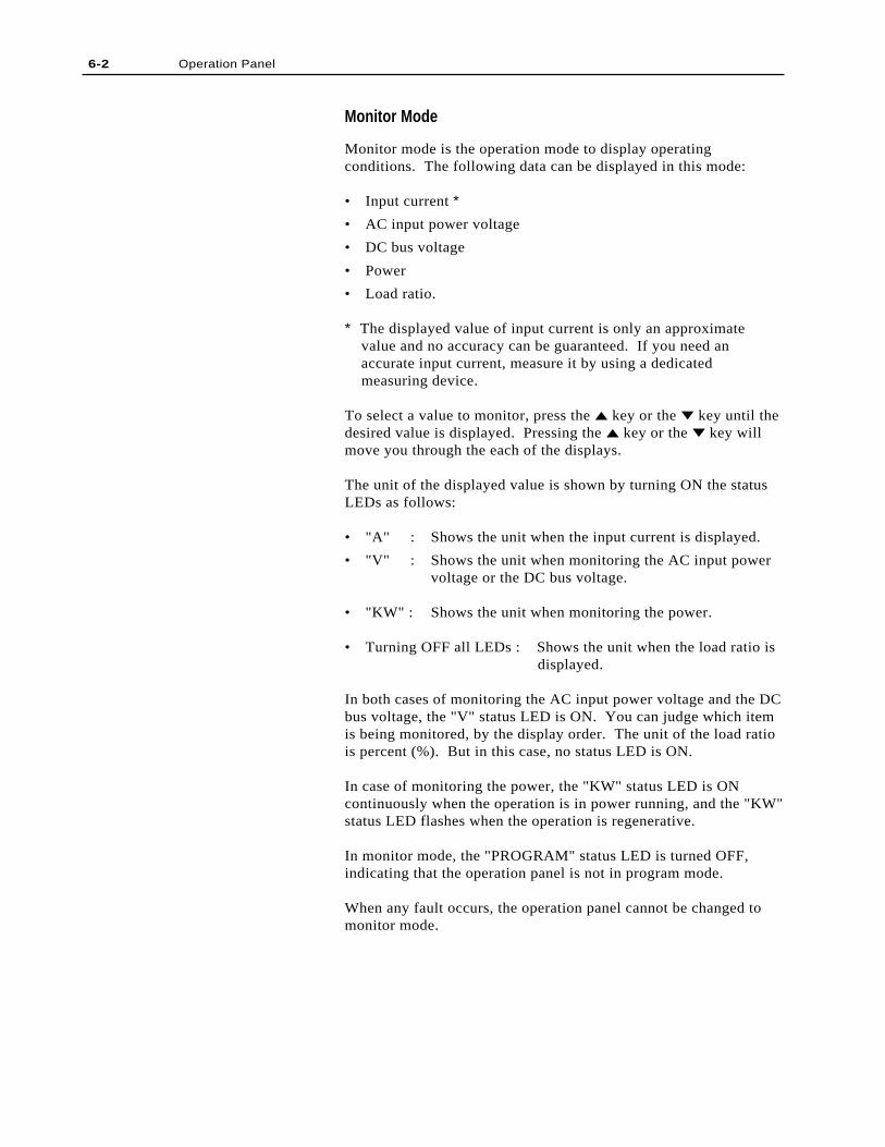
Monitor Mode
Monitor mode is the operation mode to display operatingconditions. The following data can be displayed in this mode:
• Input current *
• AC input power voltage
• DC bus voltage
• Power
• Load ratio.
* The displayed value of input current is only an approximate value and no accuracy can be guaranteed. If you need an accurate input current, measure it by using a dedicated measuring device.
To select a value to monitor, press the key or the key until thedesired value is displayed. Pressing the key or the key willmove you through the each of the displays.
The unit of the displayed value is shown by turning ON the statusLEDs as follows:
• "A" : Shows the unit when the input current is displayed.
• "V" : Shows the unit when monitoring the AC input powervoltage or the DC bus voltage.
• "KW" : Shows the unit when monitoring the power.
• Turning OFF all LEDs : Shows the unit when the load ratio is displayed.
In both cases of monitoring the AC input power voltage and the DCbus voltage, the "V" status LED is ON. You can judge which itemis being monitored, by the display order. The unit of the load ratiois percent (%). But in this case, no status LED is ON.
In case of monitoring the power, the "KW" status LED is ONcontinuously when the operation is in power running, and the "KW"status LED flashes when the operation is regenerative.
In monitor mode, the "PROGRAM" status LED is turned OFF,indicating that the operation panel is not in program mode.
When any fault occurs, the operation panel cannot be changed tomonitor mode.
6-2 Operation Panel
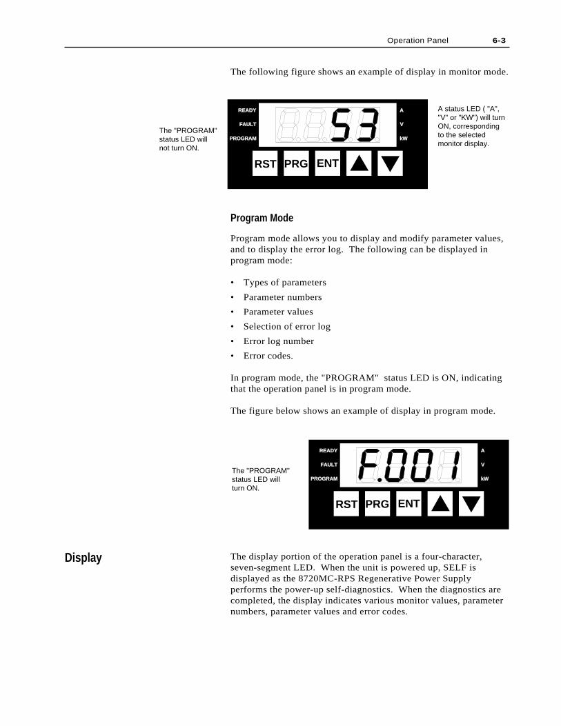
Program Mode
Program mode allows you to display and modify parameter values,and to display the error log. The following can be displayed inprogram mode:
• Types of parameters
• Parameter numbers
• Parameter values
• Selection of error log
• Error log number
• Error codes.
In program mode, the "PROGRAM" status LED is ON, indicatingthat the operation panel is in program mode.
The figure below shows an example of display in program mode.
The following figure shows an example of display in monitor mode.
6-3Operation Panel
Display
RST PRG ENT
READYREADY
FAULTFAULT
PROGRAMPROGRAM kWkW
V
A
The "PROGRAM"status LED will not turn ON.
A status LED ( "A", "V" or "KW") will turn ON, corresponding to the selectedmonitor display.
The display portion of the operation panel is a four-character,seven-segment LED. When the unit is powered up, SELF isdisplayed as the 8720MC-RPS Regenerative Power Supplyperforms the power-up self-diagnostics. When the diagnostics arecompleted, the display indicates various monitor values, parameternumbers, parameter values and error codes.
RST PRG ENT
READY
FAULT
PROGRAM kW
V
A
The "PROGRAM" status LED will turn ON.
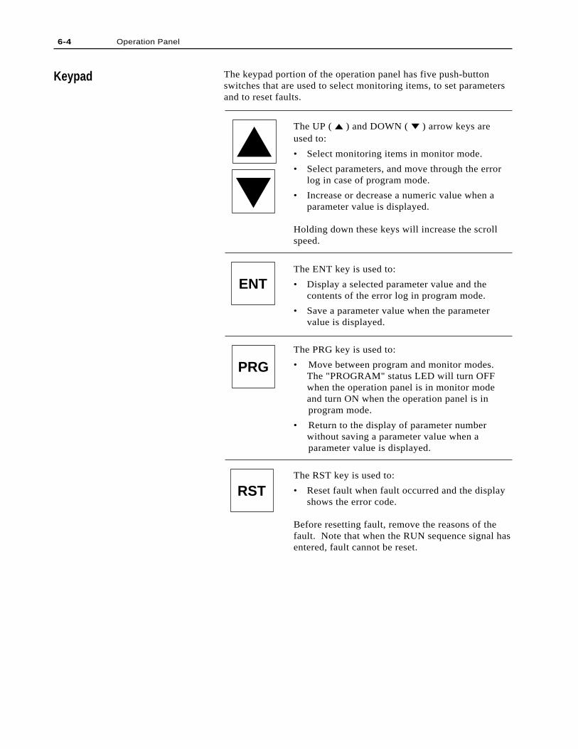
The keypad portion of the operation panel has five push-buttonswitches that are used to select monitoring items, to set parametersand to reset faults.
The UP ( ) and DOWN ( ) arrow keys areused to:
• Select monitoring items in monitor mode.
• Select parameters, and move through the errorlog in case of program mode.
• Increase or decrease a numeric value when aparameter value is displayed.
Holding down these keys will increase the scrollspeed.
The ENT key is used to:
• Display a selected parameter value and thecontents of the error log in program mode.
• Save a parameter value when the parametervalue is displayed.
The PRG key is used to:
• Move between program and monitor modes.The "PROGRAM" status LED will turn OFFwhen the operation panel is in monitor modeand turn ON when the operation panel is inprogram mode.
• Return to the display of parameter numberwithout saving a parameter value when aparameter value is displayed.
The RST key is used to:
• Reset fault when fault occurred and the displayshows the error code.
Before resetting fault, remove the reasons of thefault. Note that when the RUN sequence signal hasentered, fault cannot be reset.
6-4 Operation Panel
Keypad
ENT
PRG
RST
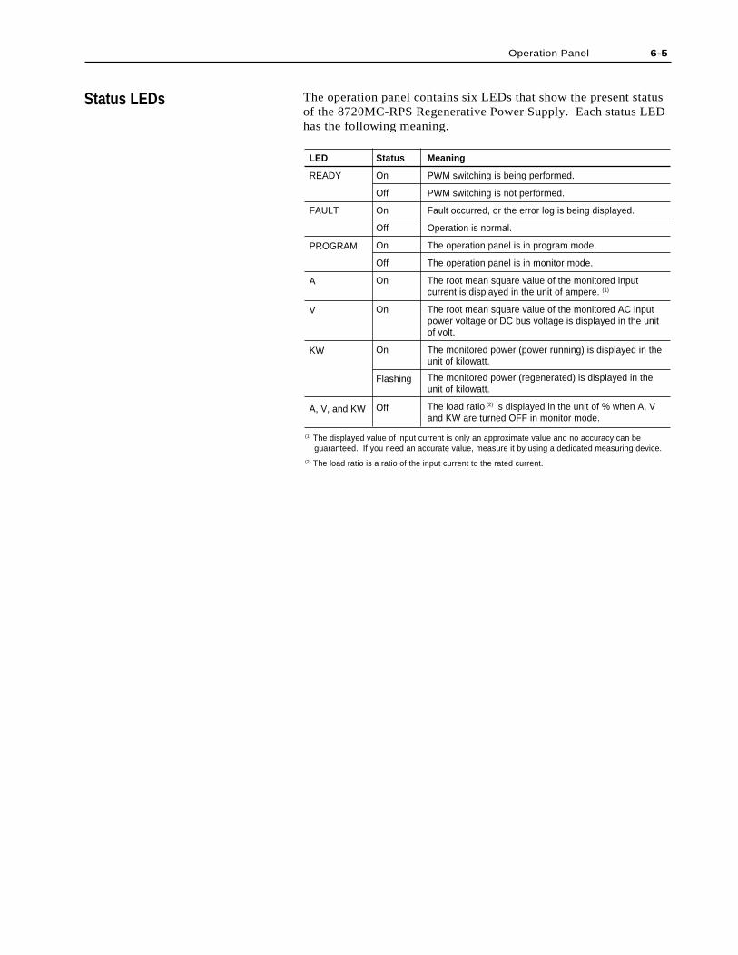
(1) The displayed value of input current is only an approximate value and no accuracy can be guaranteed. If you need an accurate value, measure it by using a dedicated measuring device.
(2) The load ratio is a ratio of the input current to the rated current.
Status LEDs
6-5Operation Panel
LED
READY
FAULT
PROGRAM
A
V
KW
A, V, and KW
Meaning
PWM switching is being performed.
PWM switching is not performed.
Fault occurred, or the error log is being displayed.
Operation is normal.
The operation panel is in program mode.
The operation panel is in monitor mode.
The root mean square value of the monitored inputcurrent is displayed in the unit of ampere. (1)
The root mean square value of the monitored AC inputpower voltage or DC bus voltage is displayed in the unitof volt.
The monitored power (power running) is displayed in theunit of kilowatt.
The monitored power (regenerated) is displayed in theunit of kilowatt.
The load ratio (2) is displayed in the unit of % when A, Vand KW are turned OFF in monitor mode.
Status
On
Off
On
Off
On
Off
On
On
On
Flashing
Off
The operation panel contains six LEDs that show the present statusof the 8720MC-RPS Regenerative Power Supply. Each status LEDhas the following meaning.

6-6
End of Chapter
Operation Panel
The parameters are used to define characteristics of the 8720MC-RPS Regenerative Power Supply. To program the unit for aspecific application, you display the appropriate parameter andadjust it as required. This chapter provides information onparameter types as well as detailed descriptions of each parameter.This chapter also describes how to access, display, and modifyparameters.
ATTENTION: Only qualified electrical personnelfamiliar with the construction and operation of thisequipment and the hazards involved should adjust andoperate this equipment. Read and understand thismanual in its entirety before proceeding. Failure toobserve this precaution could result in destruction ofthe equipment, severe bodily injury or loss of life.
There are two types of parameters:
1) User Parameters
These parameters can be adjusted or modified at any time.
2) Factory Parameters
These parameters are initially set before shipping out from thefactory. Usually, these parameters are not required to beadjusted or modified.
The Factory parameters are protected by password, and theadequate password must be set to access these parameters.Note, however, that some of these parameters cannot bemodified during operation even though the password has beenset.
Each parameter is described in detail in this chapter. The followinginformation is provided for each parameter.
• Parameter Number
A unique number is assigned to each parameter. The number ispreceded by either U or F to identify it as a User or Factoryparameter, respectively. The parameter number is shown on thedisplay of the operation panel.
• Parameter Name
A name is assigned to a parameter. The parameter name is notdisplayed when programming the 8720MC-RPS RegenerativePower Supply using the operation panel.
Chapter 7
Parameter Types
Parameters
!
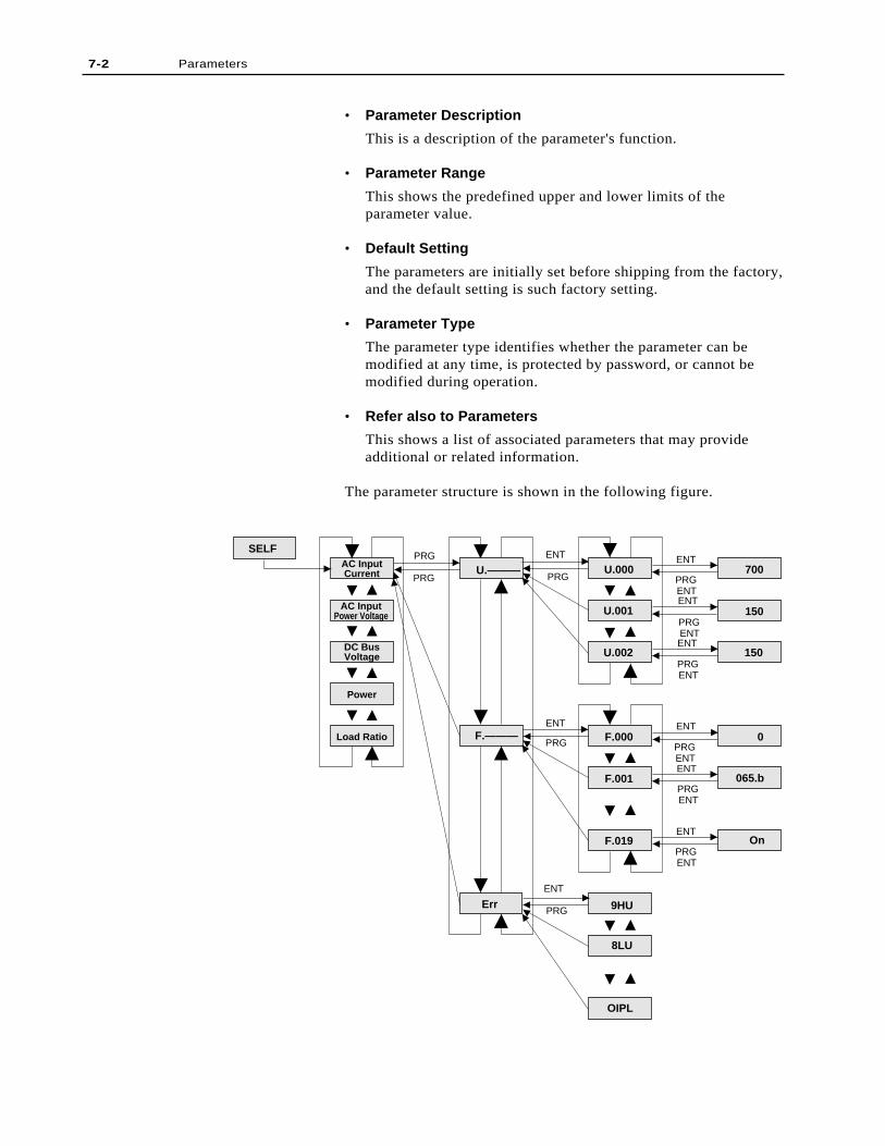
• Parameter Description
This is a description of the parameter's function.
• Parameter Range
This shows the predefined upper and lower limits of theparameter value.
• Default Setting
The parameters are initially set before shipping from the factory,and the default setting is such factory setting.
• Parameter Type
The parameter type identifies whether the parameter can bemodified at any time, is protected by password, or cannot bemodified during operation.
• Refer also to Parameters
This shows a list of associated parameters that may provideadditional or related information.
The parameter structure is shown in the following figure.
7-2 Parameters
SELF
U.———
F.———
Err
U.000
F.000
F.001
F.019
U.001
U.002
700
150
150
0
065.b
On
9HU
8LU
OIPL
PRG
PRG PRG
PRG
PRG
PRG
ENT
ENT
ENT
ENT
ENT
ENT
ENT
ENT
ENT
ENT
PRGENT
PRGENT
PRGENT
PRGENT
PRGENT
AC InputCurrent
AC InputPower Voltage
DC BusVoltage
Power
Load Ratio
Factory parameter values are password protected using ParameterF.000 (Setting Password). But even after the password has beenset, some Factory parameters cannot be modified. Such parametersmust be set after operation stopped.
Note that Parameter F.018 (Version Information) is a read-onlyparameter, and therefore, cannot be modified.
ATTENTION: Only qualified electrical personnelfamiliar with the construction and operation of thisequipment and the hazards involved should changethe Factory Parameters. Read and understand thisinstruction manual in its entirety before proceeding.Failure to change parameter values could result indestruction of the equipment, severe bodily injury orloss of life.
To display or change parameter values, the operation panel must bein program mode. Use the procedure described in the followingsections to change parameters in program mode. For calling out theerror log and resetting faults, refer to Chapter 9.
The User parameters contain basic parameters that are modifieddepending on applications of the 8720MC-RPS Regenerative PowerSupply. Use the following procedure to modify the Userparameters.
Step 1. Press the PRG key until the "PROGRAM" status LEDturns ON and the display shows "U.---". You can accessthe User parameters. If "U.---" is not shown on thedisplay, press the key or the key until "U.---"appears on the display.
Step 2. Press the ENT key. The first User parameter number(U.000) will be displayed.
Step 3. Use the key or the key to move through the Userparameters.
Step 4. When the desired parameter appears, press the ENT key.The parameter will be called out, and the parameter valuewill be displayed.
Step 5. Use the key to increment the value and the key todecrement the value.
Step 6. Press the ENT key to save changed value. Pressing theENT key will display the same parameter number again,indicating that the value was saved.
Note 1: The value is not written to the memory until the ENT keyhas been pressed.
Note 2: Pressing the PRG key will also return to the sameparameter number, without saving the value.
Parameter values are retained through a line dip or powershutdown.
7-3Parameters
Protecting Parameters withPassword
Displaying and ChangingParameter Values
User Parameters
!
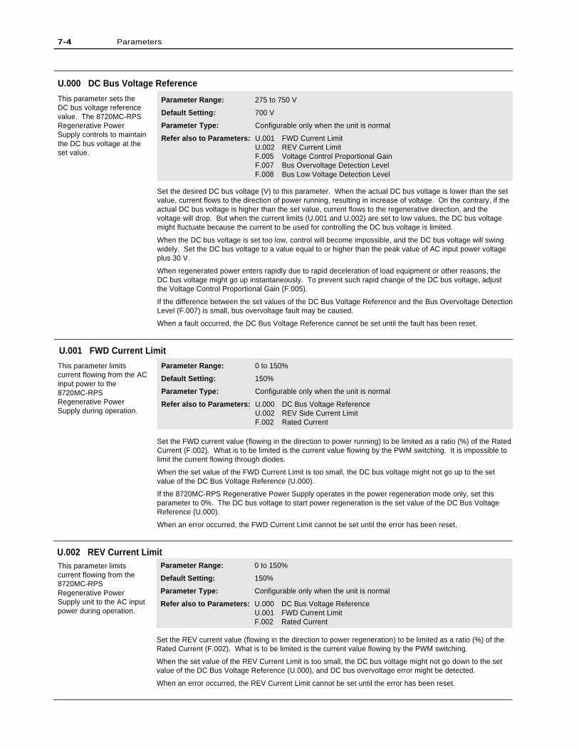
U.002 REV Current LimitThis parameter limitscurrent flowing from the8720MC-RPSRegenerative PowerSupply unit to the AC inputpower during operation.
Parameter Range: 0 to 150%
Default Setting: 150%
Parameter Type: Configurable only when the unit is normal
Refer also to Parameters: U.000 DC Bus Voltage ReferenceU.001 FWD Current LimitF.002 Rated Current
Set the REV current value (flowing in the direction to power regeneration) to be limited as a ratio (%) of theRated Current (F.002). What is to be limited is the current value flowing by the PWM switching.
When the set value of the REV Current Limit is too small, the DC bus voltage might not go down to the setvalue of the DC Bus Voltage Reference (U.000), and DC bus overvoltage error might be detected.
When an error occurred, the REV Current Limit cannot be set until the error has been reset.
Set the FWD current value (flowing in the direction to power running) to be limited as a ratio (%) of the RatedCurrent (F.002). What is to be limited is the current value flowing by the PWM switching. It is impossible tolimit the current flowing through diodes.
When the set value of the FWD Current Limit is too small, the DC bus voltage might not go up to the setvalue of the DC Bus Voltage Reference (U.000).
If the 8720MC-RPS Regenerative Power Supply operates in the power regeneration mode only, set thisparameter to 0%. The DC bus voltage to start power regeneration is the set value of the DC Bus VoltageReference (U.000).
When an error occurred, the FWD Current Limit cannot be set until the error has been reset.
U.000 DC Bus Voltage Reference
This parameter sets theDC bus voltage referencevalue. The 8720MC-RPSRegenerative PowerSupply controls to maintainthe DC bus voltage at theset value.
Parameter Range: 275 to 750 V
Default Setting: 700 V
Parameter Type: Configurable only when the unit is normal
Refer also to Parameters: U.001 FWD Current LimitU.002 REV Current LimitF.005 Voltage Control Proportional GainF.007 Bus Overvoltage Detection LevelF.008 Bus Low Voltage Detection Level
Set the desired DC bus voltage (V) to this parameter. When the actual DC bus voltage is lower than the setvalue, current flows to the direction of power running, resulting in increase of voltage. On the contrary, if theactual DC bus voltage is higher than the set value, current flows to the regenerative direction, and thevoltage will drop. But when the current limits (U.001 and U.002) are set to low values, the DC bus voltagemight fluctuate because the current to be used for controlling the DC bus voltage is limited.
When the DC bus voltage is set too low, control will become impossible, and the DC bus voltage will swingwidely. Set the DC bus voltage to a value equal to or higher than the peak value of AC input power voltageplus 30 V.
When regenerated power enters rapidly due to rapid deceleration of load equipment or other reasons, theDC bus voltage might go up instantaneously. To prevent such rapid change of the DC bus voltage, adjustthe Voltage Control Proportional Gain (F.005).
If the difference between the set values of the DC Bus Voltage Reference and the Bus Overvoltage DetectionLevel (F.007) is small, bus overvoltage fault may be caused.
When a fault occurred, the DC Bus Voltage Reference cannot be set until the fault has been reset.
U.001 FWD Current Limit
This parameter limitscurrent flowing from the ACinput power to the8720MC-RPSRegenerative PowerSupply during operation.
Parameter Range: 0 to 150%
Default Setting: 150%
Parameter Type: Configurable only when the unit is normal
Refer also to Parameters: U.000 DC Bus Voltage ReferenceU.002 REV Side Current LimitF.002 Rated Current
7-4 Parameters
ATTENTION: Only qualified electrical personnel familiar with the construction andoperation of this equipment and the hazards involved should change the FactoryParameters. Read and understand this instruction manual in its entirety beforeproceeding. Failure to change parameter values could result in destruction of theequipment, severe bodily injury or loss of life.
Once a password is set, it will be retained until power to the 8720MC-RPS Regenerative Power Supply isdisconnected. Note, therefore, that once a password is set to this parameter, the Factory parameters can bechanged at any time until the power to the unit is disconnected.
Even though a password has been set to this parameter, the password can be cancelled by setting othervalue than the password to this parameter.
Password can be set at any time while the 8720MC-RPS Regenerative Power Supply is operating orstopping, or fault occurred.
Use the following procedure to set a password:
Step 1. Press the PRG key. "U.---" will be displayed, and the status LED of "PROGRAM" will light ON.
Step 2. Press the key or the key until "F.---" is displayed.
Step 3. Press the ENT key. "F.000" will be displayed.
Step 4. Press the ENT key. "0" will be displayed.
Step 5. Press the key until "55" is displayed. (Holding down the key will increase the scroll speed.)
Step 6. Press the ENT key to enter the value.
F.000 Password
A password must be set tothis parameter to changethe Factory parameters.
Parameter Range: 0 to 999
Default Setting: 0
Parameter Type: Configurable
Refer also to Parameters: F.001 Unit Selection
Factory Parameters
7-5Parameters
!
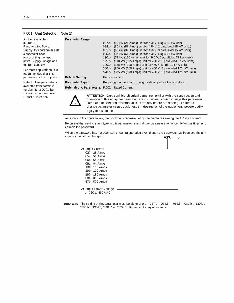
7-6 Parameters
F.001 Unit Selection (Note 1)
As the type of the8720MC-RPSRegenerative PowerSupply, this parameter setsa character coderepresenting the inputpower supply voltage andthe unit capacity.
For most applications, it isrecommended that thisparameter not be adjusted.
Note 1: This parameter isavailable from softwareversion No. 3.00 (to beshown on the parameterF.018) or later only.
Parameter Range:027.b (15 kW (28 Amps) unit for 460 V, single 15 kW unit)054.b (30 kW (56 Amps) unit for 460 V, 2 paralleled 15 kW units)081.b (45 kW (84 Amps) unit for 460 V, 3 paralleled 15 kW units)065.b (37 kW (65 Amps) unit for 460 V, single 37 kW unit)130.b (75 kW (130 Amps) unit for 460 V, 2 paralleled 37 kW units)195.b (110 kW (195 Amps) unit for 460 V, 3 paralleled 37 kW units)190.b (125 kW (190 Amps) unit for 460 V, single 125 kW unit)380.b (250 kW (380 Amps) unit for 460 V, 2 paralleled 125 kW units)570.b (375 kW (570 Amps) unit for 460 V, 3 paralleled 125 kW units)
Default Setting: Unit-dependent
Parameter Type: Requiring the password, configurable only while the unit stops
Refer also to Parameters: F.002 Rated Current
ATTENTION: Only qualified electrical personnel familiar with the construction andoperation of this equipment and the hazards involved should change this parameter.Read and understand this manual in its entirety before proceeding. Failure tochange parameter values could result in destruction of the equipment, severe bodilyinjury or loss of life.
As shown in the figure below, the unit type is represented by the numbers showing the AC input current.
Be careful that setting a unit type to this parameter resets all the parameters to factory default settings, andcancels the password.
When the password has not been set, or during operation even though the password has been set, the unitcapacity cannot be changed.
Important: The setting of this parameter must be either one of "027.b", "054.b", "065.b", "081.b", "130.b","190.b", "195.b", "380.b" or "570.b". Do not set to any other value.
!
AC Input Current 027: 28 Amps 054: 56 Amps 065: 65 Amps 081: 84 Amps 130: 130 Amps 190: 190 Amps 195: 195 Amps 380: 380 Amps 570: 570 Amps
AC Input Power Voltage b: 380 to 460 VAC
027. b
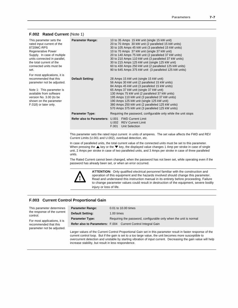
This parameter sets the rated input current in units of amperes. The set value affects the FWD and REVCurrent Limits (U.001 and U.002), overload detection, etc.
In case of paralleled units, the total current value of the connected units must be set to this parameter.When pressing the key or the key, the displayed value changes 1 Amp per stroke in case of singleunit, 2 Amps per stroke in case of two paralleled units, and 3 Amps per stroke in case of three paralleledunits.
The Rated Current cannot been changed, when the password has not been set, while operating even if thepassword has already been set, or when an error occurred.
ATTENTION: Only qualified electrical personnel familiar with the construction andoperation of this equipment and the hazards involved should change this parameter.Read and understand this instruction manual in its entirety before proceeding. Failureto change parameter values could result in destruction of the equipment, severe bodilyinjury or loss of life.
Parameter Range: 10 to 35 Amps 15 kW unit (single 15 kW unit)20 to 70 Amps 30 kW unit (2 paralleled 15 kW units)30 to 105 Amps 45 kW unit (3 paralleled 15 kW units)10 to 70 Amps 37 kW unit (single 37 kW unit)20 to 140 Amps 75 kW unit (2 paralleled 37 kW units)30 to 210 Amps 110 kW unit (3 paralleled 37 kW units)30 to 215 Amps 125 kW unit (single 125 kW unit)60 to 430 Amps 250 kW unit (2 paralleled 125 kW units)90 to 645 Amps 375 kW unit (3 paralleled 125 kW units)
Default Setting: 28 Amps 15 kW unit (single 15 kW unit)56 Amps 30 kW unit (2 paralleled 15 kW units)84 Amps 45 kW unit (3 paralleled 15 kW units)65 Amps 37 kW unit (single 37 kW unit)130 Amps 75 kW unit (2 paralleled 37 kW units)195 Amps 110 kW unit (3 paralleled 37 kW units)190 Amps 125 kW unit (single 125 kW unit)380 Amps 250 kW unit (2 paralleled 125 kW units)570 Amps 375 kW unit (3 paralleled 125 kW units)
Parameter Type: Requiring the password, configurable only while the unit stops
Refer also to Parameters: U.001 FWD Current LimitU.002 REV Current LimitF.001 Unit Selection
F.002 Rated Current (Note 1)
This parameter sets therated input current of the8720MC-RPSRegenerative PowerSupply. In case of multipleunits connected in parallel,the total current of theconnected units must beset.
For most applications, it isrecommended that thisparameter not be adjusted.
Note 1: This parameter isavailable from softwareversion No. 3.00 (to beshown on the parameterF.018) or later only.
Parameters 7-7
Larger values of the Current Control Proportional Gain set in this parameter result in faster response of thecurrent control loop. But if the gain is set to a too large value, the unit becomes more susceptible toovercurrent detection and unstable by starting vibration of input current. Decreasing the gain value will helpincrease stability, but result in less respondence.
F.003 Current Control Proportional Gain
This parameter determinesthe response of the currentcontrol.
For most applications, it isrecommended that thisparameter not be adjusted.
Parameter Range: 0.01 to 10.00 times
Default Setting: 1.00 times
Parameter Type: Requiring the password, configurable only when the unit is normal
Refer also to Parameters: F.004 Current Control Integral Gain
!
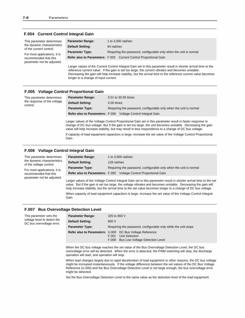
F.004 Current Control Integral Gain
This parameter determinesthe dynamic characteristicsof the current control.
For most applications, it isrecommended that thisparameter not be adjusted.
Parameter Range: 1 to 3,000 rad/sec
Default Setting: 64 rad/sec
Parameter Type: Requiring the password, configurable only when the unit is normal
Refer also to Parameters: F.003 Current Control Proportional Gain
Larger values of the Current Control Integral Gain set in this parameter result in shorter arrival time to thereference current value. If the gain is set too large, the current vibrates and becomes unstable.Decreasing the gain will help increase stability, but the arrival time to the reference current value becomeslonger to a change of input current.
7-8 Parameters
Larger values of the Voltage Control Proportional Gain set in this parameter result in faster response tochange of DC bus voltage. But If the gain is set too large, the unit becomes unstable. Decreasing the gainvalue will help increase stability, but may result in less respondence to a change of DC bus voltage.
If capacity of load equipment capacitors is large, increase the set value of the Voltage Control ProportionalGain.
F.005 Voltage Control Proportional GainThis parameter determinesthe response of the voltagecontrol.
Parameter Range: 0.01 to 30.00 times
Default Setting: 5.00 times
Parameter Type: Requiring the password, configurable only when the unit is normal
Refer also to Parameters: F.006 Voltage Control Integral Gain
F.007 Bus Overvoltage Detection Level
This parameter sets thevoltage level to detect theDC bus overvoltage error.
Parameter Range: 325 to 900 V
Default Setting: 800 V
Parameter Type: Requiring the password, configurable only while the unit stops
Refer also to Parameters: U.000 DC Bus Voltage ReferenceF.001 Unit SelectionF.008 Bus Low Voltage Detection Level
When the DC bus voltage reaches the set value of the Bus Overvoltage Detection Level, the DC busovervoltage error will be detected. When the error is detected, the PWM switching will stop, the dischargeoperation will start, and operation will stop.
When load changes largely due to rapid deceleration of load equipment or other reasons, the DC bus voltagemight be increased instantaneously. If the voltage difference between the set values of the DC Bus VoltageReference (U.000) and the Bus Overvoltage Detection Level is not large enough, the bus overvoltage errormight be detected.
Set the Bus Overvoltage Detection Level to the same value as the detection level of the load equipment.
F.006 Voltage Control Integral Gain
This parameter determinesthe dynamic characteristicsof the voltage control.
For most applications, it isrecommended that thisparameter not be adjusted.
Parameter Range: 1 to 3,000 rad/sec
Default Setting: 128 rad/sec
Parameter Type: Requiring the password, configurable only when the unit is normal
Refer also to Parameters: F.005 Voltage Control Proportional Gain
Larger values of the Voltage Control Integral Gain set in this parameter result in shorter arrival time to the setvalue. But if the gain is set too large, the voltage vibrates and becomes unstable. Decreasing the gain willhelp increase stability, but the arrival time to the set value becomes longer to a change of DC bus voltage.
When capacity of load equipment capacitors is large, increase the set value of the Voltage Control IntegralGain.
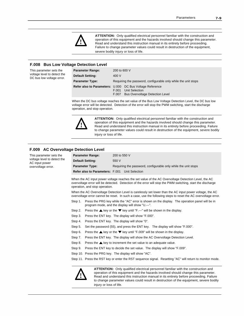
7-9Parameters
ATTENTION: Only qualified electrical personnel familiar with the construction andoperation of this equipment and the hazards involved should change this parameter.Read and understand this instruction manual in its entirety before proceeding.Failure to change parameter values could result in destruction of the equipment,severe bodily injury or loss of life.
!
F.008 Bus Low Voltage Detection LevelThis parameter sets thevoltage level to detect theDC bus low voltage error.
Parameter Range: 200 to 600 V
Default Setting: 400 V
Parameter Type: Requiring the password, configurable only while the unit stops
Refer also to Parameters: U.000 DC Bus Voltage ReferenceF.001 Unit SelectionF.007 Bus Overvoltage Detection Level
When the DC bus voltage reaches the set value of the Bus Low Voltage Detection Level, the DC bus lowvoltage error will be detected. Detection of the error will stop the PWM switching, start the dischargeoperation, and stop operation.
ATTENTION: Only qualified electrical personnel familiar with the construction andoperation of this equipment and the hazards involved should change this parameter.Read and understand this instruction manual in its entirety before proceeding. Failureto change parameter values could result in destruction of the equipment, severe bodilyinjury or loss of life.
!
F.009 AC Overvoltage Detection LevelThis parameter sets thevoltage level to detect theAC input powerovervoltage error.
Parameter Range: 200 to 550 V
Default Setting: 550 V
Parameter Type: Requiring the password, configurable only while the unit stops
Refer also to Parameters: F.001 Unit Selection
When the AC input power voltage reaches the set value of the AC Overvoltage Detection Level, the ACovervoltage error will be detected. Detection of the error will stop the PWM switching, start the dischargeoperation, and stop operation.
When the AC Overvoltage Detection Level is carelessly set lower than the AC input power voltage, the ACovervoltage error cannot be reset. In such a case, use the following steps to reset the AC overvoltage error.
Step 1. Press the PRG key while the "AC" error is shown on the display. The operation panel will be inprogram mode, and the display will show "U.---".
Step 2. Press the key or the key until "F.---" will be shown in the display.
Step 3. Press the ENT key. The display will show "F.000".
Step 4. Press the ENT key. The display will show "0".
Step 5. Set the password (55), and press the ENT key. The display will show "F.000".
Step 6. Press the key or the key until "F.009" will be shown in the display.
Step 7. Press the ENT key. The display will show the AC Overvoltage Detection Level.
Step 8. Press the key to increment the set value to an adequate value.
Step 9. Press the ENT key to decide the set value. The display will show "F.009".
Step 10. Press the PRG key. The display will show "AC".
Step 11. Press the RST key or enter the RST sequence signal. Resetting "AC" will return to monitor mode.
ATTENTION: Only qualified electrical personnel familiar with the construction andoperation of this equipment and the hazards involved should change this parameter.Read and understand this instruction manual in its entirety before proceeding. Failureto change parameter values could result in destruction of the equipment, severe bodilyinjury or loss of life.
!
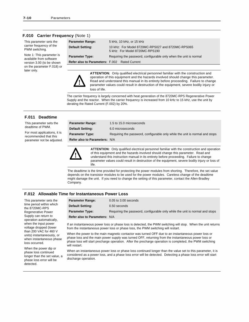
ATTENTION: Only qualified electrical personnel familiar with the construction and operationof this equipment and the hazards involved should change this parameter. Read andunderstand this instruction manual in its entirety before proceeding. Failure to changeparameter values could result in destruction of the equipment, severe bodily injury or loss oflife.
The deadtime is the time provided for protecting the power modules from shorting. Therefore, the set valuedepends on the transistor modules to be used for the power modules. Careless change of the deadtimemight damage the unit. If you need to change the setting of this parameter, contact the Allen-BradleyCompany.
Parameter Range: 5 kHz, 10 kHz, or 15 kHz
Default Setting: 10 kHz: For Model 8720MC-RPS027 and 8720MC-RPS0655 kHz: For Model 8720MC-RPS190
Parameter Type: Requiring the password, configurable only when the unit is normal
Refer also to Parameters: F.002 Rated Current
7-10 Parameters
F.010 Carrier Frequency (Note 1)This parameter sets thecarrier frequency of thePWM switching.
Note 1: This parameter isavailable from softwareversion 3.00 (to be shownon the parameter F.018) orlater only.
ATTENTION: Only qualified electrical personnel familiar with the construction andoperation of this equipment and the hazards involved should change this parameter.Read and understand this manual in its entirety before proceeding. Failure to changeparameter values could result in destruction of the equipment, severe bodily injury orloss of life.
The carrier frequency is largely concerned with heat generation of the 8720MC-RPS Regenerative PowerSupply and the reactor. When the carrier frequency is increased from 10 kHz to 15 kHz, use the unit byderating the Rated Current (F.002) by 20%.
!
F.011 DeadtimeThis parameter sets thedeadtime of PWM.
For most applications, it isrecommended that thisparameter not be adjusted.
Parameter Range: 1.5 to 15.0 microseconds
Default Setting: 6.0 microseconds
Parameter Type: Requiring the password, configurable only while the unit is normal and stops
Refer also to Parameters: N/A
!
F.012 Allowable Time for Instantaneous Power Loss
This parameter sets thetime period within whichthe 8720MC-RPSRegenerative PowerSupply can return tooperation automatically,when the input powervoltage dropped (lowerthan 200 VAC for 460 Vunits) instantaneously, orwhen instantaneous phaseloss occurred.
When the power dip orphase loss continuedlonger than the set value, aphase loss error will bedetected.
Parameter Range: 0.05 to 3.00 seconds
Default Setting: 0.50 seconds
Parameter Type: Requiring the password, configurable only while the unit is normal and stops
Refer also to Parameters: N/A
If an instantaneous power loss or phase loss is detected, the PWM switching will stop. When the unit returnsfrom the instantaneous power loss or phase loss, the PWM switching will restart.
When the power to the main magnetic contactor was turned OFF due to an instantaneous power loss orphase loss and the main power supply was turned OFF, returning from the instantaneous power loss orphase loss will start precharge operation. After the precharge operation is completed, the PWM switchingwill restart.
When an instantaneous power loss or phase loss continued longer than the value set to this parameter, it isconsidered as a power loss, and a phase loss error will be detected. Detecting a phase loss error will startdischarge operation.
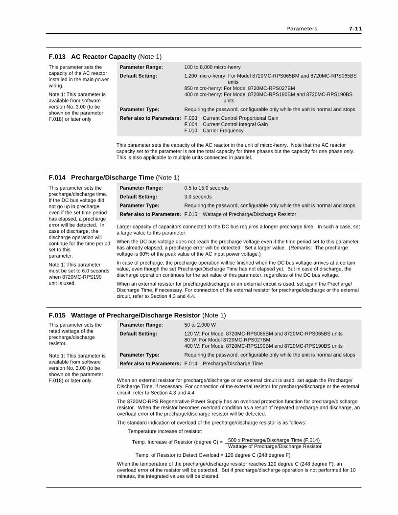
7-11Parameters
Parameter Range: 100 to 8,000 micro-henry
Default Setting: 1,200 micro-henry: For Model 8720MC-RPS065BM and 8720MC-RPS065BS units
850 micro-henry: For Model 8720MC-RPS027BM400 micro-henry: For Model 8720MC-RPS190BM and 8720MC-RPS190BS
units
Parameter Type: Requiring the password, configurable only while the unit is normal and stops
Refer also to Parameters: F.003 Current Control Proportional GainF.004 Current Control Integral GainF.010 Carrier Frequency
F.013 AC Reactor Capacity (Note 1)
This parameter sets thecapacity of the AC reactorinstalled in the main powerwiring.
Note 1: This parameter isavailable from softwareversion No. 3.00 (to beshown on the parameterF.018) or later only
This parameter sets the capacity of the AC reactor in the unit of micro-henry. Note that the AC reactorcapacity set to the parameter is not the total capacity for three phases but the capacity for one phase only.This is also applicable to multiple units connected in parallel.
Larger capacity of capacitors connected to the DC bus requires a longer precharge time. In such a case, seta large value to this parameter.
When the DC bus voltage does not reach the precharge voltage even if the time period set to this parameterhas already elapsed, a precharge error will be detected. Set a larger value. (Remarks: The prechargevoltage is 90% of the peak value of the AC input power voltage.)
In case of precharge, the precharge operation will be finished when the DC bus voltage arrives at a certainvalue, even though the set Precharge/Discharge Time has not elapsed yet. But in case of discharge, thedischarge operation continues for the set value of this parameter, regardless of the DC bus voltage.
When an external resistor for precharge/discharge or an external circuit is used, set again the Precharge/Discharge Time, if necessary. For connection of the external resistor for precharge/discharge or the externalcircuit, refer to Section 4.3 and 4.4.
F.014 Precharge/Discharge Time (Note 1)
This parameter sets theprecharge/discharge time.If the DC bus voltage didnot go up in prechargeeven if the set time periodhas elapsed, a prechargeerror will be detected. Incase of discharge, thedischarge operation willcontinue for the time periodset to thisparameter.
Note 1: This parametermust be set to 6.0 secondswhen 8720MC-RPS190unit is used.
Parameter Range: 0.5 to 15.0 seconds
Default Setting: 3.0 seconds
Parameter Type: Requiring the password, configurable only while the unit is normal and stops
Refer also to Parameters: F.015 Wattage of Precharge/Discharge Resistor
When an external resistor for precharge/discharge or an external circuit is used, set again the Precharge/Discharge Time, if necessary. For connection of the external resistor for precharge/discharge or the externalcircuit, refer to Section 4.3 and 4.4.
The 8720MC-RPS Regenerative Power Supply has an overload protection function for precharge/dischargeresistor. When the resistor becomes overload condition as a result of repeated precharge and discharge, anoverload error of the precharge/discharge resistor will be detected.
The standard indication of overload of the precharge/discharge resistor is as follows:
Temperature increase of resistor:
500 x Precharge/Discharge Time (F.014) Wattage of Precharge/Discharge Resistor
Temp. of Resistor to Detect Overload = 120 degree C (248 degree F)
When the temperature of the precharge/discharge resistor reaches 120 degree C (248 degree F), anoverload error of the resistor will be detected. But if precharge/discharge operation is not performed for 10minutes, the integrated values will be cleared.
Temp. Increase of Resistor (degree C) =
F.015 Wattage of Precharge/Discharge Resistor (Note 1)This parameter sets therated wattage of theprecharge/dischargeresistor.
Note 1: This parameter isavailable from softwareversion No. 3.00 (to beshown on the parameterF.018) or later only.
Parameter Range: 50 to 2,000 W
Default Setting: 120 W: For Model 8720MC-RPS065BM and 8720MC-RPS065BS units80 W: For Model 8720MC-RPS027BM400 W: For Model 8720MC-RPS190BM and 8720MC-RPS190BS units
Parameter Type: Requiring the password, configurable only while the unit is normal and stops
Refer also to Parameters: F.014 Precharge/Discharge Time
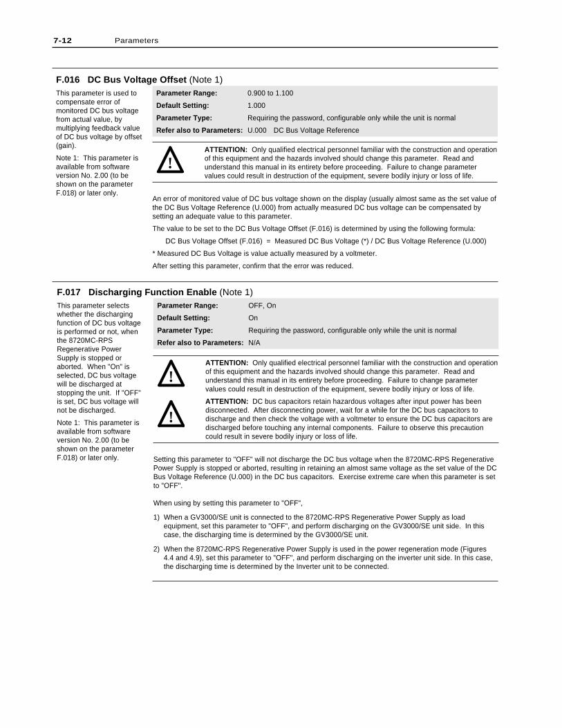
7-12 Parameters
F.016 DC Bus Voltage Offset (Note 1)This parameter is used tocompensate error ofmonitored DC bus voltagefrom actual value, bymultiplying feedback valueof DC bus voltage by offset(gain).
Note 1: This parameter isavailable from softwareversion No. 2.00 (to beshown on the parameterF.018) or later only.
Parameter Range: 0.900 to 1.100
Default Setting: 1.000
Parameter Type: Requiring the password, configurable only while the unit is normal
Refer also to Parameters: U.000 DC Bus Voltage Reference
ATTENTION: Only qualified electrical personnel familiar with the construction and operationof this equipment and the hazards involved should change this parameter. Read andunderstand this manual in its entirety before proceeding. Failure to change parametervalues could result in destruction of the equipment, severe bodily injury or loss of life.
An error of monitored value of DC bus voltage shown on the display (usually almost same as the set value ofthe DC Bus Voltage Reference (U.000) from actually measured DC bus voltage can be compensated bysetting an adequate value to this parameter.
The value to be set to the DC Bus Voltage Offset (F.016) is determined by using the following formula:
DC Bus Voltage Offset (F.016) = Measured DC Bus Voltage (*) / DC Bus Voltage Reference (U.000)
* Measured DC Bus Voltage is value actually measured by a voltmeter.
After setting this parameter, confirm that the error was reduced.
!
F.017 Discharging Function Enable (Note 1)This parameter selectswhether the dischargingfunction of DC bus voltageis performed or not, whenthe 8720MC-RPSRegenerative PowerSupply is stopped oraborted. When "On" isselected, DC bus voltagewill be discharged atstopping the unit. If "OFF"is set, DC bus voltage willnot be discharged.
Note 1: This parameter isavailable from softwareversion No. 2.00 (to beshown on the parameterF.018) or later only.
Parameter Range: OFF, On
Default Setting: On
Parameter Type: Requiring the password, configurable only while the unit is normal
Refer also to Parameters: N/A
ATTENTION: Only qualified electrical personnel familiar with the construction and operationof this equipment and the hazards involved should change this parameter. Read andunderstand this manual in its entirety before proceeding. Failure to change parametervalues could result in destruction of the equipment, severe bodily injury or loss of life.
ATTENTION: DC bus capacitors retain hazardous voltages after input power has beendisconnected. After disconnecting power, wait for a while for the DC bus capacitors todischarge and then check the voltage with a voltmeter to ensure the DC bus capacitors aredischarged before touching any internal components. Failure to observe this precautioncould result in severe bodily injury or loss of life.
Setting this parameter to "OFF" will not discharge the DC bus voltage when the 8720MC-RPS RegenerativePower Supply is stopped or aborted, resulting in retaining an almost same voltage as the set value of the DCBus Voltage Reference (U.000) in the DC bus capacitors. Exercise extreme care when this parameter is setto "OFF".
When using by setting this parameter to "OFF",
1) When a GV3000/SE unit is connected to the 8720MC-RPS Regenerative Power Supply as loadequipment, set this parameter to "OFF", and perform discharging on the GV3000/SE unit side. In thiscase, the discharging time is determined by the GV3000/SE unit.
2) When the 8720MC-RPS Regenerative Power Supply is used in the power regeneration mode (Figures4.4 and 4.9), set this parameter to "OFF", and perform discharging on the inverter unit side. In this case,the discharging time is determined by the Inverter unit to be connected.
!
!
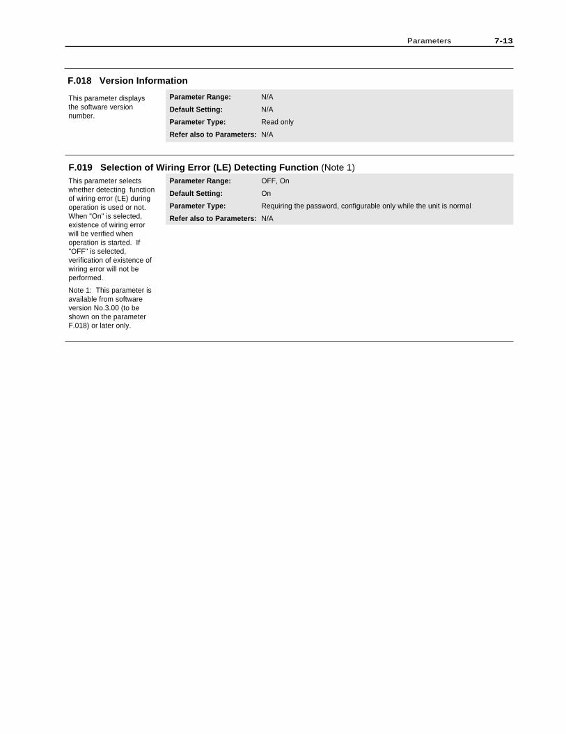
Parameters 7-13
F.019 Selection of Wiring Error (LE) Detecting Function (Note 1)This parameter selectswhether detecting functionof wiring error (LE) duringoperation is used or not.When "On" is selected,existence of wiring errorwill be verified whenoperation is started. If"OFF" is selected,verification of existence ofwiring error will not beperformed.
Note 1: This parameter isavailable from softwareversion No.3.00 (to beshown on the parameterF.018) or later only.
Parameter Range: OFF, On
Default Setting: On
Parameter Type: Requiring the password, configurable only while the unit is normal
Refer also to Parameters: N/A
F.018 Version Information
This parameter displaysthe software versionnumber.
Parameter Range: N/A
Default Setting: N/A
Parameter Type: Read only
Refer also to Parameters: N/A

7-14 Parameters
End of Chapter

This chapter describes contents of error codes and how to correctproblems.
When an error occurs in the 8720MC-RPS Regenerative PowerSupply, an error code corresponding to the error is shown on thedisplay. The error codes are two- or three-letter codes flashing onthe display.
When an error occurs while the unit stops, the precharge operationand the PWM switching cannot be started by entering the RUNsequence signal, and thus, operation cannot be started, until theerror has been reset.
When an error occurs during operation, the PWM switching willstop, the discharge operation will start and the unit will stop. Inthis case, the unit cannot be started until the error has been reset.
For resetting an error, press the RST key or enter the RESETsequence signal after removing the cause of the error. In eithercase, the error cannot be reset when the RUN sequence signal hasbeen entered.
If multiple errors occurred at a time, the corresponding error codeswill be scrolled flashing one by one.
It is possible to view all the parameters, while an error occurred andthe error code is being displayed. But in such a case, anyparameters except some special ones cannot be changed. To view aparameter, press the PRG key while an error code is displayed.Pressing the PRG key will display "U.---", indicating the operationpanel is changed to program mode.
A maximum of ten error codes can be stored in the error log. Thelast error that occurred is the first one to appear on the displaywhen accessing the error log. The last error will be identified withthe highest number (up to 9).
The first error that occurred will appear as the last one in the errorlog. The first error will be identified by the number 0.
When viewing the error log, pressing the key or the key willscroll the error codes.
The error log will be retained even if power to the unit is lost. Ifthe error log is full, more entries can be added by clearing olderentries. If you desire to clear the error log, press the RST key whilethe error log is displayed.
In the course of error processing, an error code (LE*) other thanoriginal errors may be incidentally displayed.
Chapter 8
Error Codes and Warning Buzzer
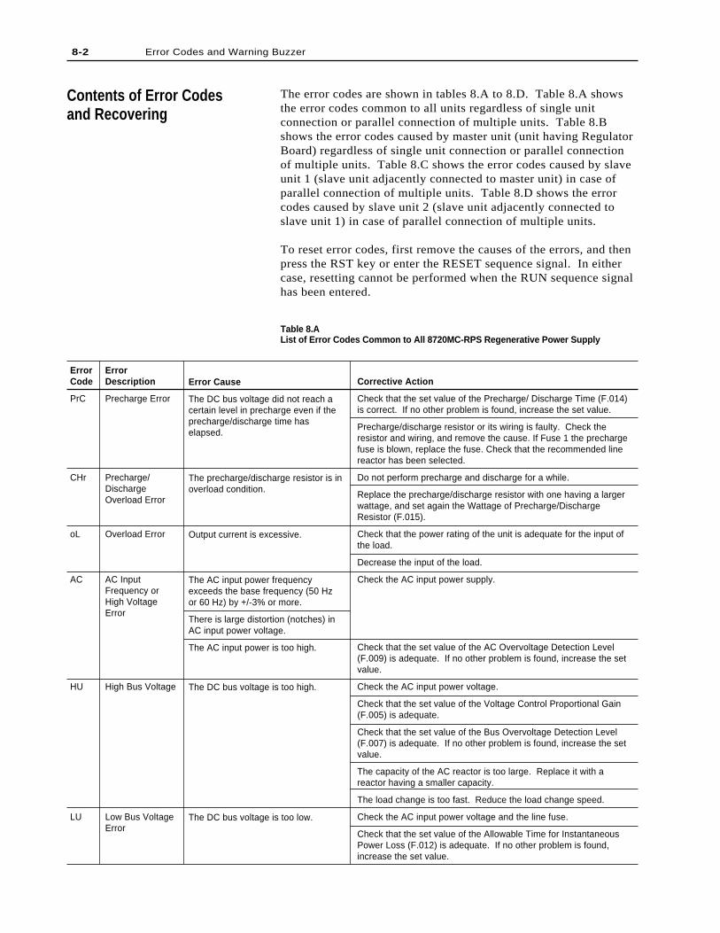
The error codes are shown in tables 8.A to 8.D. Table 8.A showsthe error codes common to all units regardless of single unitconnection or parallel connection of multiple units. Table 8.Bshows the error codes caused by master unit (unit having RegulatorBoard) regardless of single unit connection or parallel connectionof multiple units. Table 8.C shows the error codes caused by slaveunit 1 (slave unit adjacently connected to master unit) in case ofparallel connection of multiple units. Table 8.D shows the errorcodes caused by slave unit 2 (slave unit adjacently connected toslave unit 1) in case of parallel connection of multiple units.
To reset error codes, first remove the causes of the errors, and thenpress the RST key or enter the RESET sequence signal. In eithercase, resetting cannot be performed when the RUN sequence signalhas been entered.
Table 8.AList of Error Codes Common to All 8720MC-RPS Regenerative Power Supply
ErrorCode
PrC
CHr
oL
AC
HU
LU
ErrorDescription
Precharge Error
Precharge/DischargeOverload Error
Overload Error
AC InputFrequency orHigh VoltageError
High Bus Voltage
Low Bus VoltageError
Error Cause
The DC bus voltage did not reach acertain level in precharge even if theprecharge/discharge time haselapsed.
The precharge/discharge resistor is inoverload condition.
Output current is excessive.
The AC input power frequencyexceeds the base frequency (50 Hzor 60 Hz) by +/-3% or more.
There is large distortion (notches) inAC input power voltage.
The AC input power is too high.
The DC bus voltage is too high.
The DC bus voltage is too low.
Corrective Action
Check that the set value of the Precharge/ Discharge Time (F.014)is correct. If no other problem is found, increase the set value.
Precharge/discharge resistor or its wiring is faulty. Check theresistor and wiring, and remove the cause. If Fuse 1 the prechargefuse is blown, replace the fuse. Check that the recommended linereactor has been selected.
Do not perform precharge and discharge for a while.
Replace the precharge/discharge resistor with one having a largerwattage, and set again the Wattage of Precharge/DischargeResistor (F.015).
Check that the power rating of the unit is adequate for the input ofthe load.
Decrease the input of the load.
Check the AC input power supply.
Check that the set value of the AC Overvoltage Detection Level(F.009) is adequate. If no other problem is found, increase the setvalue.
Check the AC input power voltage.
Check that the set value of the Voltage Control Proportional Gain(F.005) is adequate.
Check that the set value of the Bus Overvoltage Detection Level(F.007) is adequate. If no other problem is found, increase the setvalue.
The capacity of the AC reactor is too large. Replace it with areactor having a smaller capacity.
The load change is too fast. Reduce the load change speed.
Check the AC input power voltage and the line fuse.
Check that the set value of the Allowable Time for InstantaneousPower Loss (F.012) is adequate. If no other problem is found,increase the set value.
8-2 Error Codes and Warning Buzzer
Contents of Error Codesand Recovering
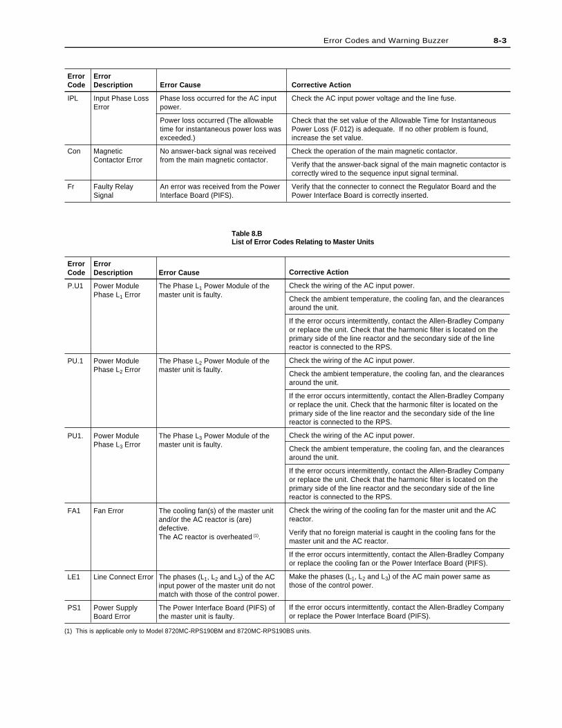
ErrorCode
P.U1
PU.1
PU1.
FA1
LE1
PS1
ErrorDescription
Power ModulePhase L1 Error
Power ModulePhase L2 Error
Power ModulePhase L3 Error
Fan Error
Line Connect Error
Power SupplyBoard Error
Corrective Action
Check the wiring of the AC input power.
Check the ambient temperature, the cooling fan, and the clearancesaround the unit.
If the error occurs intermittently, contact the Allen-Bradley Companyor replace the unit. Check that the harmonic filter is located on theprimary side of the line reactor and the secondary side of the linereactor is connected to the RPS.
Check the wiring of the cooling fan for the master unit and the ACreactor.
Verify that no foreign material is caught in the cooling fans for themaster unit and the AC reactor.
If the error occurs intermittently, contact the Allen-Bradley Companyor replace the cooling fan or the Power Interface Board (PIFS).
Make the phases (L1, L2 and L3) of the AC main power same asthose of the control power.
If the error occurs intermittently, contact the Allen-Bradley Companyor replace the Power Interface Board (PIFS).
Error Cause
The Phase L1 Power Module of themaster unit is faulty.
The Phase L2 Power Module of themaster unit is faulty.
The Phase L3 Power Module of themaster unit is faulty.
The cooling fan(s) of the master unitand/or the AC reactor is (are)defective.The AC reactor is overheated (1).
The phases (L1, L2 and L3) of the ACinput power of the master unit do notmatch with those of the control power.
The Power Interface Board (PIFS) ofthe master unit is faulty.
Table 8.BList of Error Codes Relating to Master Units
ErrorCode
IPL
Con
Fr
ErrorDescription
Input Phase LossError
MagneticContactor Error
Faulty RelaySignal
Error Cause
Phase loss occurred for the AC inputpower.
Power loss occurred (The allowabletime for instantaneous power loss wasexceeded.)
No answer-back signal was receivedfrom the main magnetic contactor.
An error was received from the PowerInterface Board (PIFS).
Corrective Action
Check the AC input power voltage and the line fuse.
Check that the set value of the Allowable Time for InstantaneousPower Loss (F.012) is adequate. If no other problem is found,increase the set value.
Check the operation of the main magnetic contactor.
Verify that the answer-back signal of the main magnetic contactor iscorrectly wired to the sequence input signal terminal.
Verify that the connecter to connect the Regulator Board and thePower Interface Board is correctly inserted.
8-3Error Codes and Warning Buzzer
(1) This is applicable only to Model 8720MC-RPS190BM and 8720MC-RPS190BS units.
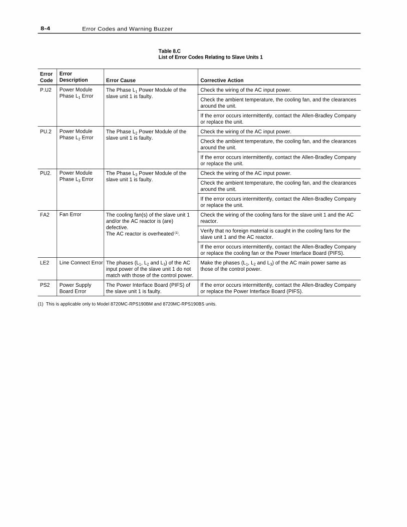
8-4 Error Codes and Warning Buzzer
ErrorCode
P.U2
PU.2
PU2.
FA2
LE2
PS2
ErrorDescription
Power ModulePhase L1 Error
Power ModulePhase L2 Error
Power ModulePhase L3 Error
Fan Error
Line Connect Error
Power SupplyBoard Error
Error Cause
The Phase L1 Power Module of theslave unit 1 is faulty.
The Phase L2 Power Module of theslave unit 1 is faulty.
The Phase L3 Power Module of theslave unit 1 is faulty.
The cooling fan(s) of the slave unit 1and/or the AC reactor is (are)defective.The AC reactor is overheated (1).
The phases (L1, L2 and L3) of the ACinput power of the slave unit 1 do notmatch with those of the control power.
The Power Interface Board (PIFS) ofthe slave unit 1 is faulty.
Corrective Action
Check the wiring of the AC input power.
Check the ambient temperature, the cooling fan, and the clearancesaround the unit.
If the error occurs intermittently, contact the Allen-Bradley Companyor replace the unit.
Check the wiring of the AC input power.
Check the ambient temperature, the cooling fan, and the clearancesaround the unit.
If the error occurs intermittently, contact the Allen-Bradley Companyor replace the unit.
Check the wiring of the AC input power.
Check the ambient temperature, the cooling fan, and the clearancesaround the unit.
If the error occurs intermittently, contact the Allen-Bradley Companyor replace the unit.
Check the wiring of the cooling fans for the slave unit 1 and the ACreactor.
Verify that no foreign material is caught in the cooling fans for theslave unit 1 and the AC reactor.
If the error occurs intermittently, contact the Allen-Bradley Companyor replace the cooling fan or the Power Interface Board (PIFS).
Make the phases (L1, L2 and L3) of the AC main power same asthose of the control power.
If the error occurs intermittently, contact the Allen-Bradley Companyor replace the Power Interface Board (PIFS).
Table 8.CList of Error Codes Relating to Slave Units 1
(1) This is applicable only to Model 8720MC-RPS190BM and 8720MC-RPS190BS units.
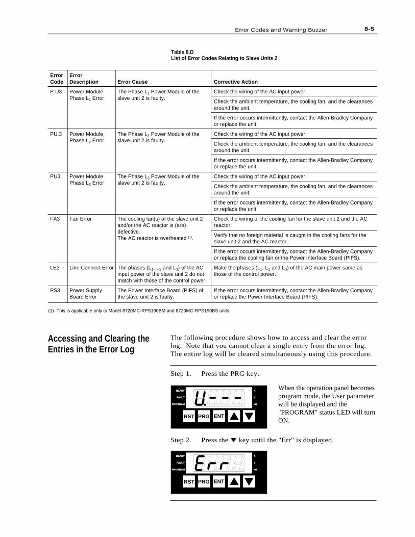
The following procedure shows how to access and clear the errorlog. Note that you cannot clear a single entry from the error log.The entire log will be cleared simultaneously using this procedure.
Step 1. Press the PRG key.
When the operation panel becomesprogram mode, the User parameterwill be displayed and the"PROGRAM" status LED will turnON.
Step 2. Press the key until the "Err" is displayed.
8-5Error Codes and Warning Buzzer
ErrorCode
P.U3
PU.3
PU3.
FA3
LE3
PS3
ErrorDescription
Power ModulePhase L1 Error
Power ModulePhase L2 Error
Power ModulePhase L3 Error
Fan Error
Line Connect Error
Power SupplyBoard Error
Error Cause
The Phase L1 Power Module of theslave unit 2 is faulty.
The Phase L2 Power Module of theslave unit 2 is faulty.
The Phase L3 Power Module of theslave unit 2 is faulty.
The cooling fan(s) of the slave unit 2and/or the AC reactor is (are)defective.The AC reactor is overheated (1).
The phases (L1, L2 and L3) of the ACinput power of the slave unit 2 do notmatch with those of the control power.
The Power Interface Board (PIFS) ofthe slave unit 2 is faulty.
Corrective Action
Check the wiring of the AC input power.
Check the ambient temperature, the cooling fan, and the clearancesaround the unit.
If the error occurs intermittently, contact the Allen-Bradley Companyor replace the unit.
Check the wiring of the AC input power.
Check the ambient temperature, the cooling fan, and the clearancesaround the unit.
If the error occurs intermittently, contact the Allen-Bradley Companyor replace the unit.
Check the wiring of the AC input power.
Check the ambient temperature, the cooling fan, and the clearancesaround the unit.
If the error occurs intermittently, contact the Allen-Bradley Companyor replace the unit.
Check the wiring of the cooling fan for the slave unit 2 and the ACreactor.
Verify that no foreign material is caught in the cooling fans for theslave unit 2 and the AC reactor.
If the error occurs intermittently, contact the Allen-Bradley Companyor replace the cooling fan or the Power Interface Board (PIFS).
Make the phases (L1, L2 and L3) of the AC main power same asthose of the control power.
If the error occurs intermittently, contact the Allen-Bradley Companyor replace the Power Interface Board (PIFS).
Table 8.DList of Error Codes Relating to Slave Units 2
Accessing and Clearing theEntries in the Error Log
RST PRG ENT
READYREADY
FAULTFAULT
PROGRAMPROGRAM kWkW
V
A
RST PRG ENT
READYREADY
FAULTFAULT
PROGRAMPROGRAM kWkW
V
A
(1) This is applicable only to Model 8720MC-RPS190BM and 8720MC-RPS190BS units.
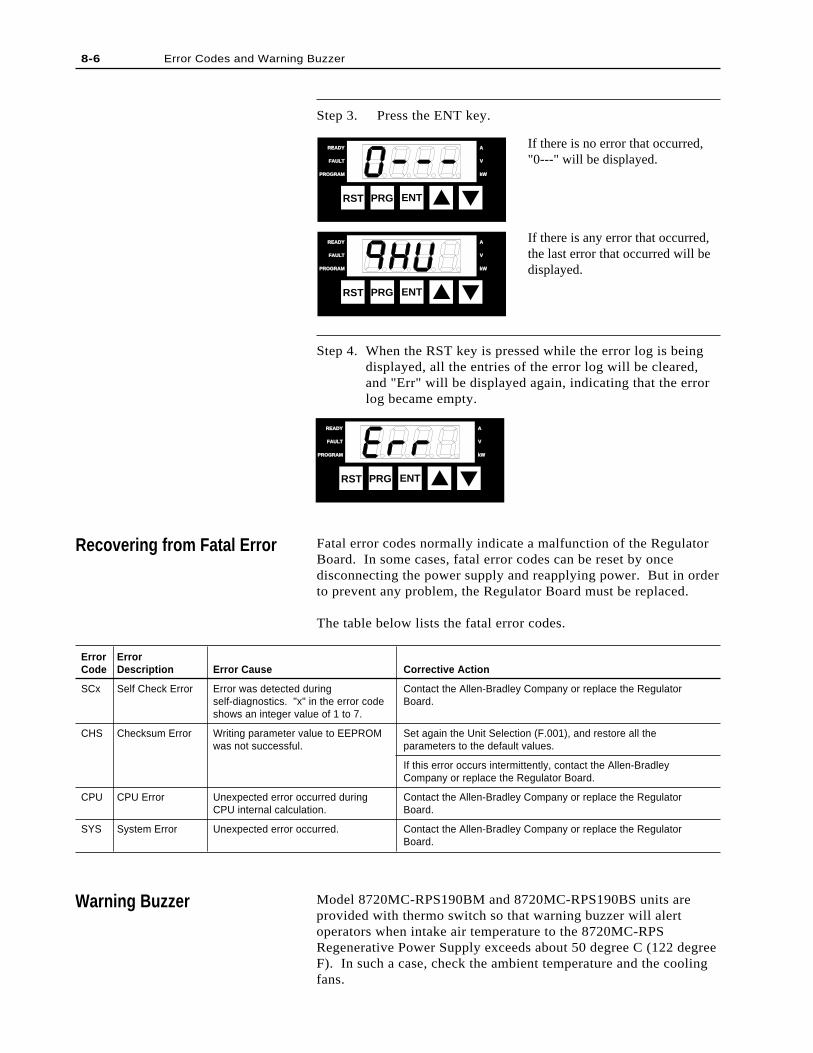
Fatal error codes normally indicate a malfunction of the RegulatorBoard. In some cases, fatal error codes can be reset by oncedisconnecting the power supply and reapplying power. But in orderto prevent any problem, the Regulator Board must be replaced.
The table below lists the fatal error codes.
ErrorCode
SCx
CHS
CPU
SYS
ErrorDescription
Self Check Error
Checksum Error
CPU Error
System Error
Error Cause
Error was detected duringself-diagnostics. "x" in the error codeshows an integer value of 1 to 7.
Writing parameter value to EEPROMwas not successful.
Unexpected error occurred duringCPU internal calculation.
Unexpected error occurred.
Corrective Action
Contact the Allen-Bradley Company or replace the RegulatorBoard.
Set again the Unit Selection (F.001), and restore all theparameters to the default values.
If this error occurs intermittently, contact the Allen-BradleyCompany or replace the Regulator Board.
Contact the Allen-Bradley Company or replace the RegulatorBoard.
Contact the Allen-Bradley Company or replace the RegulatorBoard.
Step 3. Press the ENT key.
If there is no error that occurred,"0---" will be displayed.
If there is any error that occurred,the last error that occurred will bedisplayed.
Step 4. When the RST key is pressed while the error log is beingdisplayed, all the entries of the error log will be cleared,and "Err" will be displayed again, indicating that the errorlog became empty.
8-6 Error Codes and Warning Buzzer
Recovering from Fatal Error
RST PRG ENT
READYREADY
FAULTFAULT
PROGRAMPROGRAM kWkW
V
A
RST PRG ENT
READYREADY
FAULTFAULT
PROGRAMPROGRAM kWkW
V
A
RST PRG ENT
READYREADY
FAULTFAULT
PROGRAMPROGRAM kWkW
V
A
Warning Buzzer Model 8720MC-RPS190BM and 8720MC-RPS190BS units areprovided with thermo switch so that warning buzzer will alertoperators when intake air temperature to the 8720MC-RPSRegenerative Power Supply exceeds about 50 degree C (122 degreeF). In such a case, check the ambient temperature and the coolingfans.
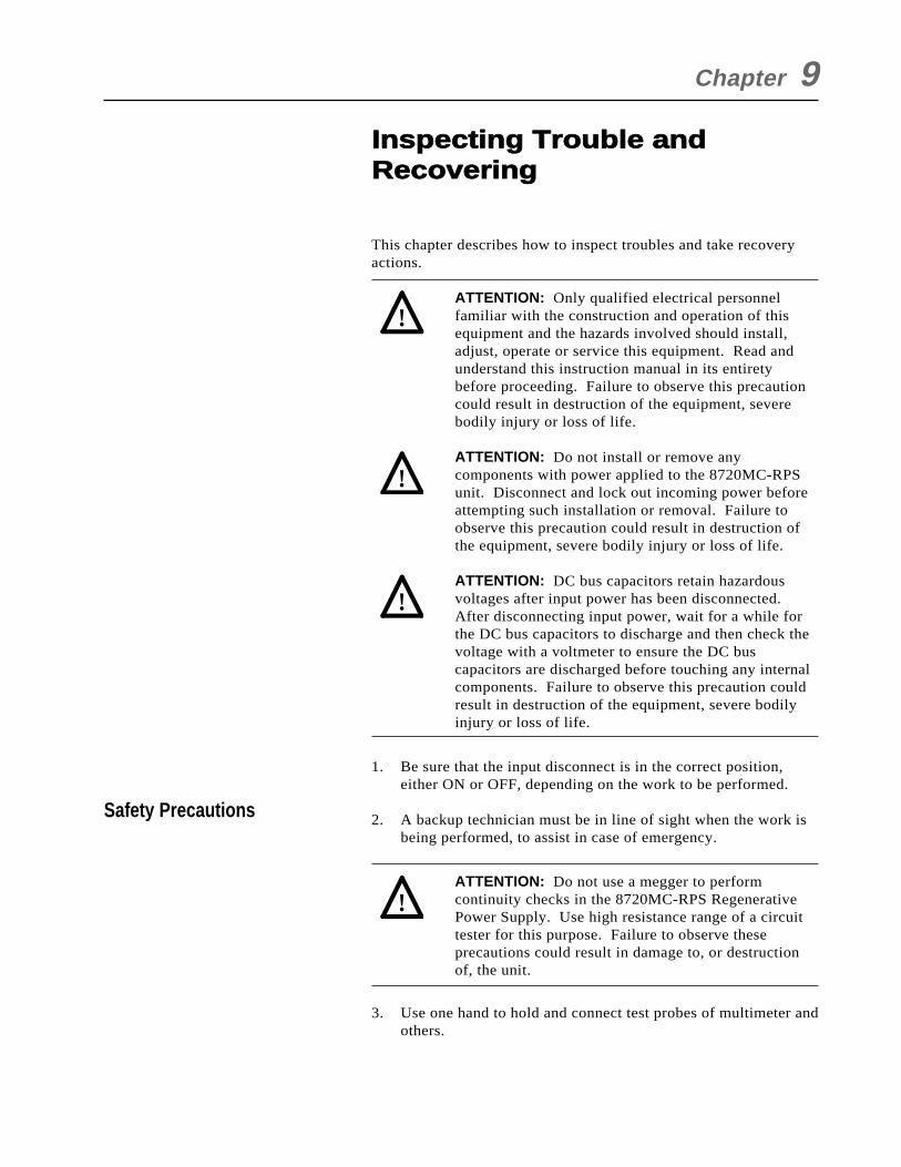
This chapter describes how to inspect troubles and take recoveryactions.
ATTENTION: Only qualified electrical personnelfamiliar with the construction and operation of thisequipment and the hazards involved should install,adjust, operate or service this equipment. Read andunderstand this instruction manual in its entiretybefore proceeding. Failure to observe this precautioncould result in destruction of the equipment, severebodily injury or loss of life.
ATTENTION: Do not install or remove anycomponents with power applied to the 8720MC-RPSunit. Disconnect and lock out incoming power beforeattempting such installation or removal. Failure toobserve this precaution could result in destruction ofthe equipment, severe bodily injury or loss of life.
ATTENTION: DC bus capacitors retain hazardousvoltages after input power has been disconnected.After disconnecting input power, wait for a while forthe DC bus capacitors to discharge and then check thevoltage with a voltmeter to ensure the DC buscapacitors are discharged before touching any internalcomponents. Failure to observe this precaution couldresult in destruction of the equipment, severe bodilyinjury or loss of life.
1. Be sure that the input disconnect is in the correct position,either ON or OFF, depending on the work to be performed.
2. A backup technician must be in line of sight when the work isbeing performed, to assist in case of emergency.
ATTENTION: Do not use a megger to performcontinuity checks in the 8720MC-RPS RegenerativePower Supply. Use high resistance range of a circuittester for this purpose. Failure to observe theseprecautions could result in damage to, or destructionof, the unit.
3. Use one hand to hold and connect test probes of multimeter andothers.
Chapter 9
Safety Precautions
Inspecting Trouble and Recovering
!
!
!
!
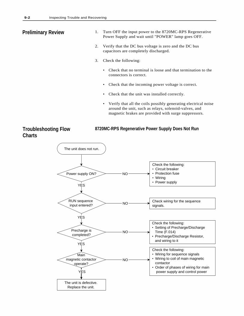
1. Turn OFF the input power to the 8720MC-RPS RegenerativePower Supply and wait until "POWER" lamp goes OFF.
2. Verify that the DC bus voltage is zero and the DC buscapacitors are completely discharged.
3. Check the following:
• Check that no terminal is loose and that termination to theconnectors is correct.
• Check that the incoming power voltage is correct.
• Check that the unit was installed correctly.
• Verify that all the coils possibly generating electrical noisearound the unit, such as relays, solenoid-valves, andmagnetic brakes are provided with surge suppressors.
8720MC-RPS Regenerative Power Supply Does Not Run
9-2 Inspecting Trouble and Recovering
Preliminary Review
Troubleshooting FlowCharts
The unit does not run.
Power supply ON?
YES
YES
YES
YES
Check the following:• Circuit breaker• Protection fuse• Wiring• Power supply
Check wiring for the sequence signals.
Check the following:• Setting of Precharge/Discharge Time (F.014)• Precharge/Discharge Resistor, and wiring to it
Check the following:• Wiring for sequence signals• Wiring to coil of main magnetic contactor• Order of phases of wiring for main power supply and control power
NO
NO
NO
NO
RUN sequence input entered?
Precharge iscompleted?
Mainmagnetic contactor
operate?
The unit is defective.Replace the unit.
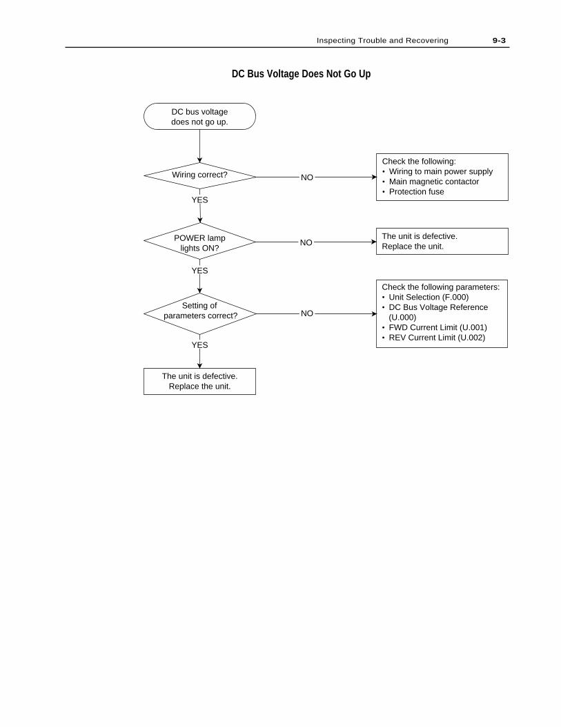
DC Bus Voltage Does Not Go Up
9-3Inspecting Trouble and Recovering
DC bus voltagedoes not go up.
Wiring correct?
POWER lamplights ON?
Setting of parameters correct?
The unit is defective.Replace the unit.
YES
YES
YES
Check the following:• Wiring to main power supply• Main magnetic contactor• Protection fuse
The unit is defective.Replace the unit.
Check the following parameters:• Unit Selection (F.000)• DC Bus Voltage Reference (U.000)• FWD Current Limit (U.001)• REV Current Limit (U.002)
NO
NO
NO

9-4 Inspecting Trouble and Recovering
End of Chapter
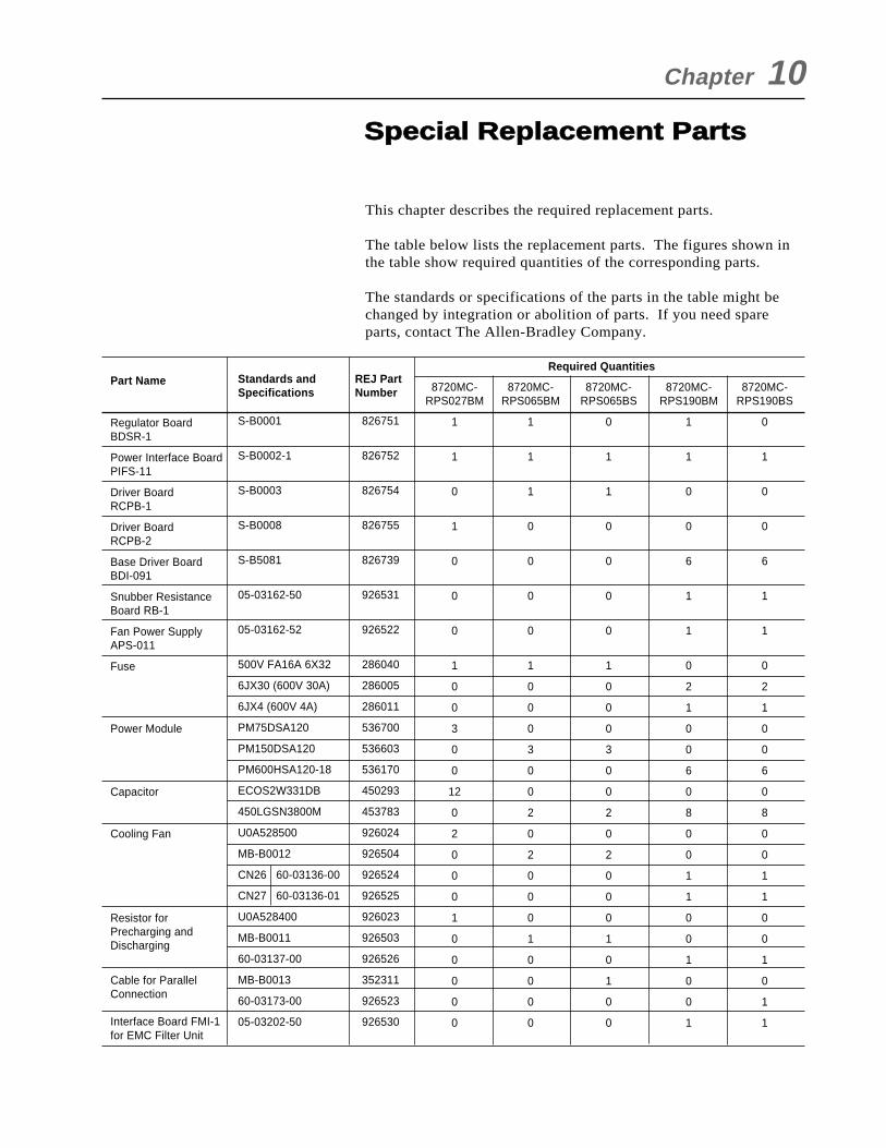
8720MC-RPS027BM
1
1
0
1
0
0
0
1
0
0
3
0
0
12
0
2
0
0
0
1
0
0
0
0
0
This chapter describes the required replacement parts.
The table below lists the replacement parts. The figures shown inthe table show required quantities of the corresponding parts.
The standards or specifications of the parts in the table might bechanged by integration or abolition of parts. If you need spareparts, contact The Allen-Bradley Company.
Part Name
Regulator BoardBDSR-1
Power Interface BoardPIFS-11
Driver BoardRCPB-1
Driver BoardRCPB-2
Base Driver BoardBDI-091
Snubber ResistanceBoard RB-1
Fan Power SupplyAPS-011
Fuse
Power Module
Capacitor
Cooling Fan
Resistor forPrecharging andDischarging
Cable for ParallelConnection
Interface Board FMI-1for EMC Filter Unit
Standards andSpecifications
S-B0001
S-B0002-1
S-B0003
S-B0008
S-B5081
05-03162-50
05-03162-52
500V FA16A 6X32
6JX30 (600V 30A)
6JX4 (600V 4A)
PM75DSA120
PM150DSA120
PM600HSA120-18
ECOS2W331DB
450LGSN3800M
U0A528500
MB-B0012
CN26 60-03136-00
CN27 60-03136-01
U0A528400
MB-B0011
60-03137-00
MB-B0013
60-03173-00
05-03202-50
REJ PartNumber
826751
826752
826754
826755
826739
926531
926522
286040
286005
286011
536700
536603
536170
450293
453783
926024
926504
926524
926525
926023
926503
926526
352311
926523
926530
Required Quantities
Chapter 10
Special Replacement Parts
8720MC-RPS065BM
1
1
1
0
0
0
0
1
0
0
0
3
0
0
2
0
2
0
0
0
1
0
0
0
0
8720MC-RPS065BS
0
1
1
0
0
0
0
1
0
0
0
3
0
0
2
0
2
0
0
0
1
0
1
0
0
8720MC-RPS190BM
1
1
0
0
6
1
1
0
2
1
0
0
6
0
8
0
0
1
1
0
0
1
0
0
1
8720MC-RPS190BS
0
1
0
0
6
1
1
0
2
1
0
0
6
0
8
0
0
1
1
0
0
1
0
1
1

10-2 Special Replacement Parts
Decide the quantities of spare parts in consideration of the numberof the connected units.
8720MC-RPS027BM
0
0
Part Name
Capacitor forEMC Filter Unit
Cooling Fan forACL Unit
Standards andSpecifications
SME35LGSN 68000
60-03177-00
REJ PartNumber
450071
926529
Required Quantities
8720MC-RPS065BM
0
0
8720MC-RPS065BS
0
0
8720MC-RPS190BM
2
2
8720MC-RPS190BS
2
2
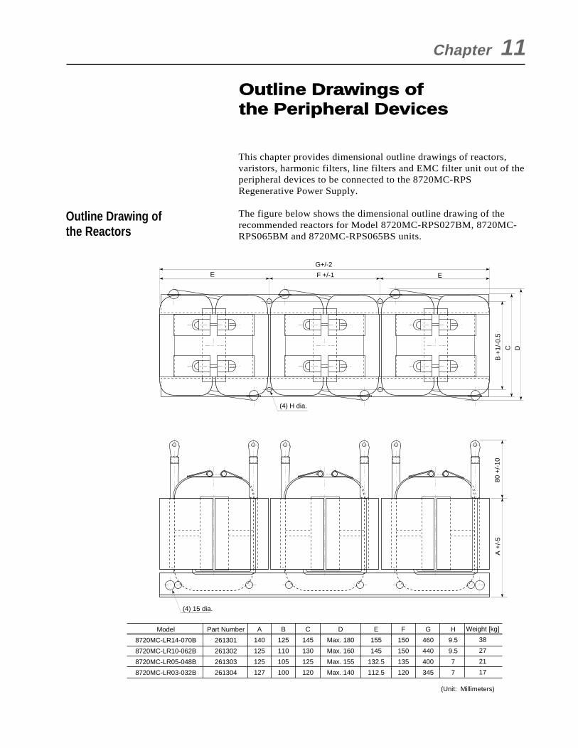
This chapter provides dimensional outline drawings of reactors,varistors, harmonic filters, line filters and EMC filter unit out of theperipheral devices to be connected to the 8720MC-RPSRegenerative Power Supply.
The figure below shows the dimensional outline drawing of therecommended reactors for Model 8720MC-RPS027BM, 8720MC-RPS065BM and 8720MC-RPS065BS units.
Chapter 11
Outline Drawing ofthe Reactors
Outline Drawings of the Peripheral Devices
Part Number
261301
261302
261303
261304
Model
8720MC-LR14-070B
8720MC-LR10-062B
8720MC-LR05-048B
8720MC-LR03-032B
A
140
125
125
127
B
125
110
105
100
C
145
130
125
120
D
Max. 180
Max. 160
Max. 155
Max. 140
Weight [kg]
38
27
21
17
E
155
145
132.5
112.5
F
150
150
135
120
G
460
440
400
345
H
9.5
9.5
7
7
(4) 15 dia.
(4) H dia.
A +
/-5
G+/-2
F +/-1
80 +
/-10
B +
1/-0
.5
C D
E E
(Unit: Millimeters)
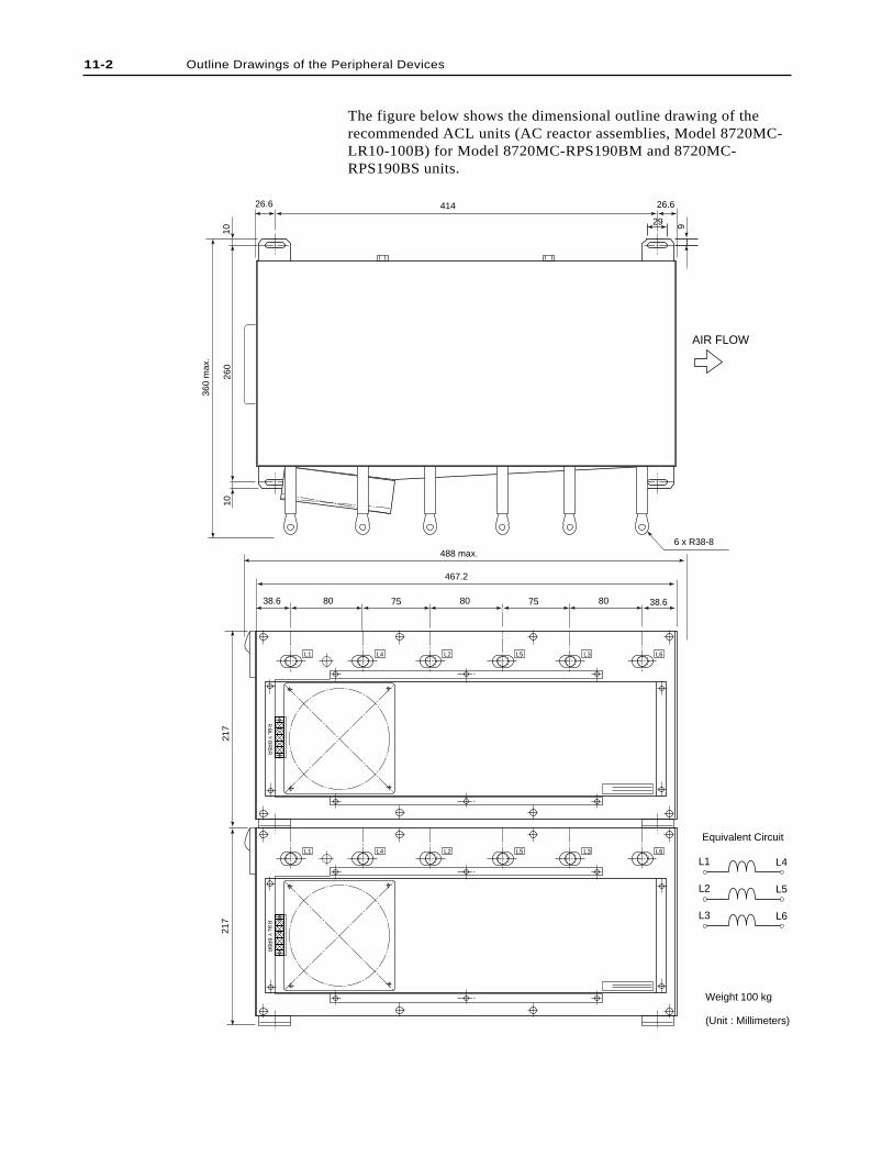
The figure below shows the dimensional outline drawing of therecommended ACL units (AC reactor assemblies, Model 8720MC-LR10-100B) for Model 8720MC-RPS190BM and 8720MC-RPS190BS units.
11-2 Outline Drawings of the Peripheral Devices
RB
RB
RY
BL
L1 L4 L2 L5 L3 L6
RB
RB
RY
BL
L1 L4 L2 L5 L3 L6
217
217
488 max.
467.2
38.6 38.680 80 8075 75
360
max
.
260
1010
26.6 26.6414
29 9
6 x R38-8
AIR FLOW
Weight 100 kg
(Unit : Millimeters)
L3 L6
L2 L5
L1 L4
Equivalent Circuit
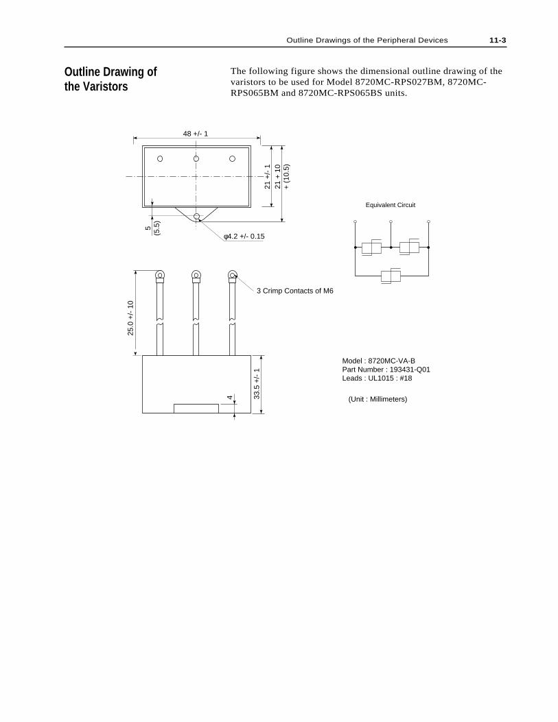
Outline Drawings of the Peripheral Devices 11-3
Outline Drawing ofthe Varistors
The following figure shows the dimensional outline drawing of thevaristors to be used for Model 8720MC-RPS027BM, 8720MC-RPS065BM and 8720MC-RPS065BS units.
48 +/- 1
5(5
.5)
21 +
/- 1
21 +
10
+ (
10.5
)
φ4.2 +/- 0.15
33.5
+/-
1
4
25.0
+/-
10
Equivalent Circuit
3 Crimp Contacts of M6
(Unit : Millimeters)
Model : 8720MC-VA-BPart Number : 193431-Q01Leads : UL1015 : #18
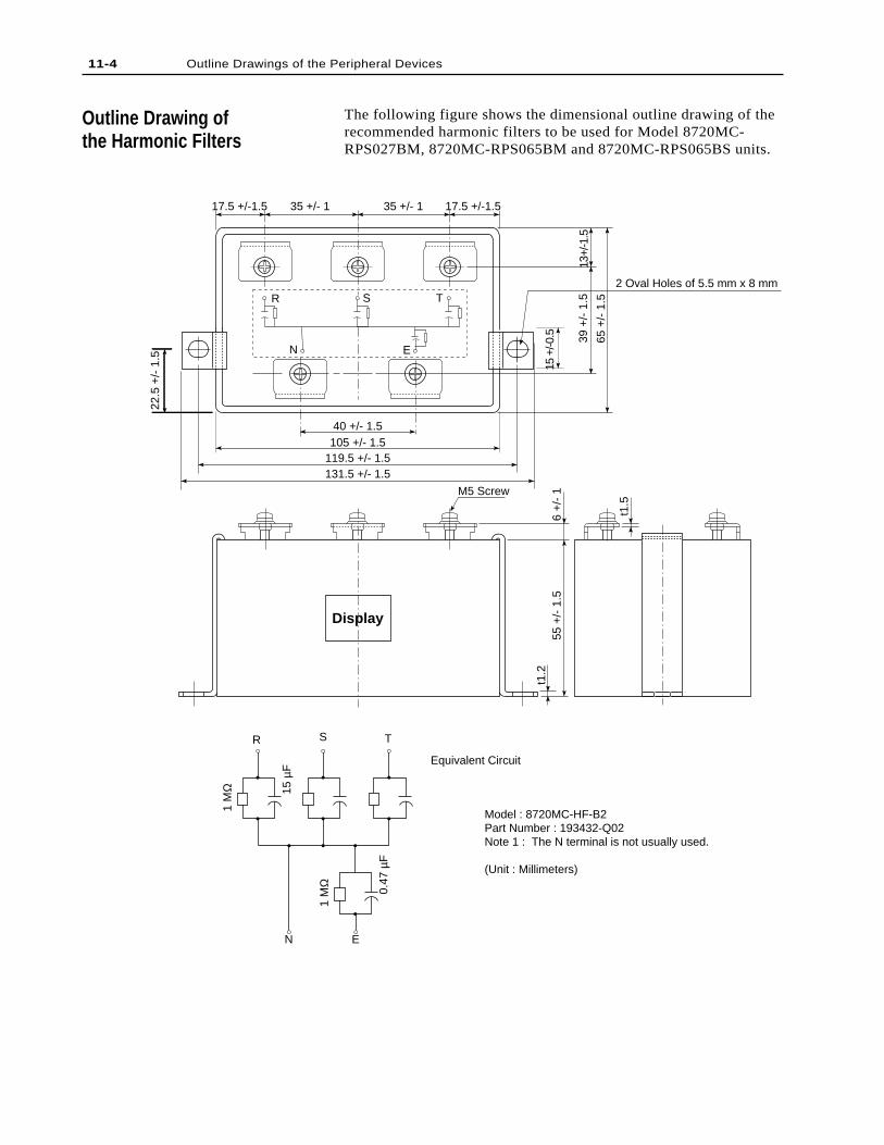
11-4 Outline Drawings of the Peripheral Devices
Outline Drawing ofthe Harmonic Filters
The following figure shows the dimensional outline drawing of therecommended harmonic filters to be used for Model 8720MC-RPS027BM, 8720MC-RPS065BM and 8720MC-RPS065BS units.
17.5 +/-1.5 17.5 +/-1.535 +/- 1 35 +/- 1
R
105 +/- 1.540 +/- 1.5
119.5 +/- 1.5131.5 +/- 1.5
15 +
/-0.5 39
+/-
1.5
13+/
-1.5
65 +
/- 1
.5
2 Oval Holes of 5.5 mm x 8 mm
M5 Screw
t1.5
t1.2
55 +
/- 1
.5
22.5
+/-
1.5
6 +
/- 1
Display
Model : 8720MC-HF-B2Part Number : 193432-Q02Note 1 : The N terminal is not usually used.
(Unit : Millimeters)
N E
S TR
N E
Equivalent Circuit
1 M
Ω 15 µ
F
1 M
Ω
0.47
µF
S T
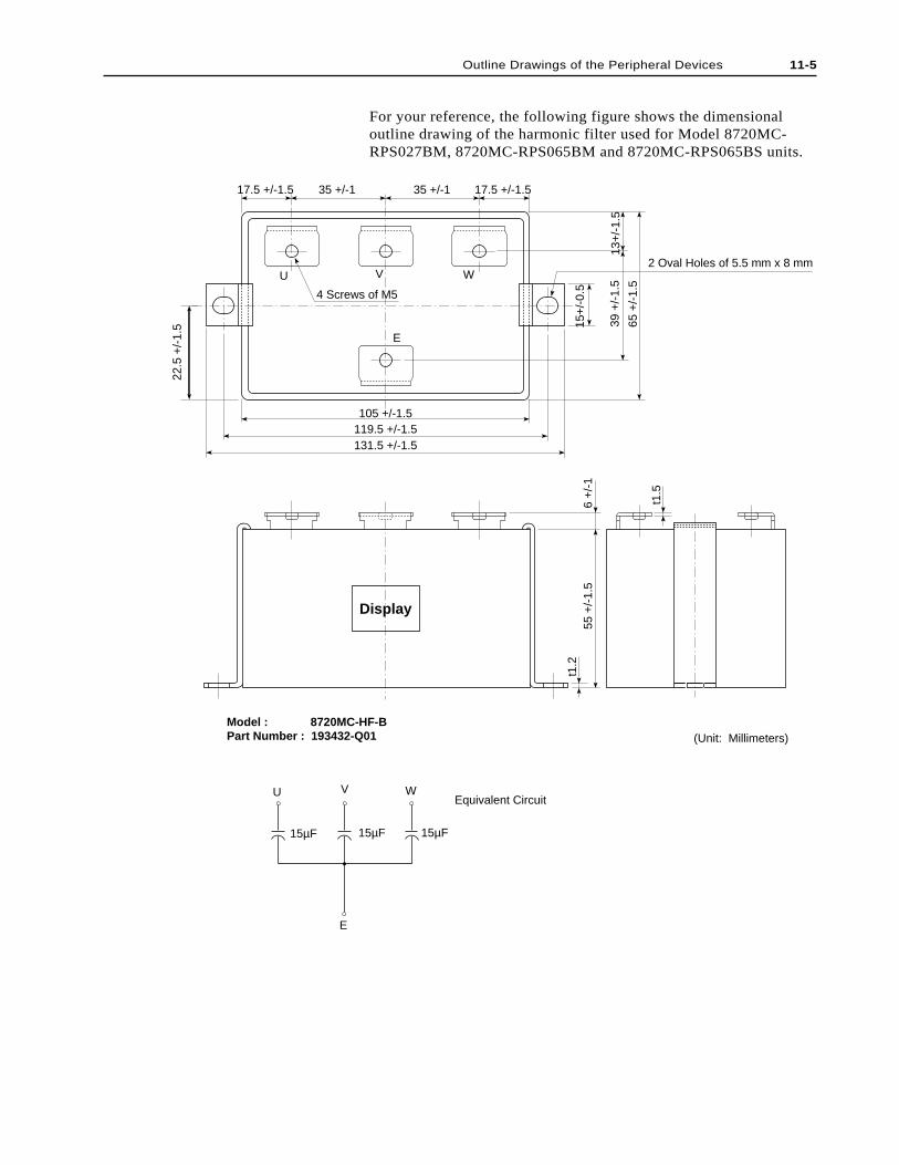
Outline Drawings of the Peripheral Devices 11-5
17.5 +/-1.5 17.5 +/-1.535 +/-1 35 +/-1
U V W
E
105 +/-1.5119.5 +/-1.5131.5 +/-1.5
15+
/-0.
5
22.5
+/-
1.5 39
+/-
1.5
13+
/-1.
5
65 +
/-1.
5
2 Oval Holes of 5.5 mm x 8 mm
t1.5
t1.2
55 +
/-1.
56
+/-
1
Display
Model : 8720MC-HF-BPart Number : 193432-Q01 (Unit: Millimeters)
Equivalent Circuit
4 Screws of M5
V WU
E
15µF15µF 15µF
For your reference, the following figure shows the dimensionaloutline drawing of the harmonic filter used for Model 8720MC-RPS027BM, 8720MC-RPS065BM and 8720MC-RPS065BS units.
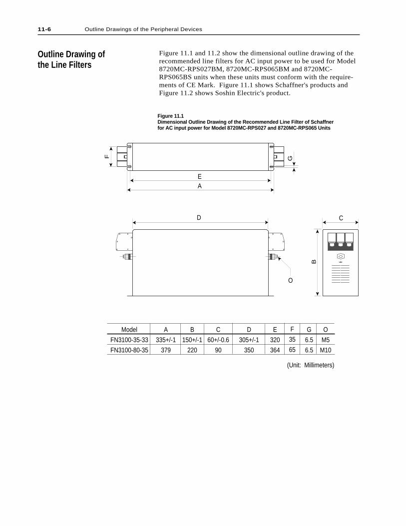
11-6 Outline Drawings of the Peripheral Devices
Figure 11.1 and 11.2 show the dimensional outline drawing of therecommended line filters for AC input power to be used for Model8720MC-RPS027BM, 8720MC-RPS065BM and 8720MC-RPS065BS units when these units must conform with the require-ments of CE Mark. Figure 11.1 shows Schaffner's products andFigure 11.2 shows Soshin Electric's product.
Outline Drawing ofthe Line Filters
Figure 11.1Dimensional Outline Drawing of the Recommended Line Filter of Schaffnerfor AC input power for Model 8720MC-RPS027 and 8720MC-RPS065 Units
A
B
CD
E
F G
O
Model
FN3100-35-33
FN3100-80-35
A
335+/-1
379
B
150+/-1
220
C
60+/-0.6
90
D
305+/-1
350
E
320
364
F
35
65
G
6.5
6.5
O
M5
M10
(Unit: Millimeters)
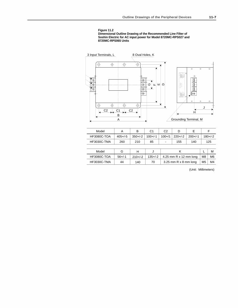
Figure 11.2Dimensional Outline Drawing of the Recommended Line Filter ofSoshin Electric for AC input power for Model 8720MC-RPS027 and8720MC-RPS065 Units
(Unit: Millimeters)
3 Input Terminals, L
C2 H
J
DEFG
AB
C2 C1
8 Oval Holes, K
Grounding Terminal, M
Model
HF3080C-TOA
HF3030C-TMA
Model
HF3080C-TOA
HF3030C-TMA
A
405+/-5
260
B
350+/-2
210
C1
100+/-1
85
C2
100+/1
-
D
220+/-2
155
E
200+/-1
140
F
180+/-2
125
G
56+/-1
44
H
210+/-2
140
J
135+/-2
70
K
4.25 mm R x 12 mm long
3.25 mm R x 8 mm long
L
M8
M5
M
M6
M4
Outline Drawings of the Peripheral Devices 11-7
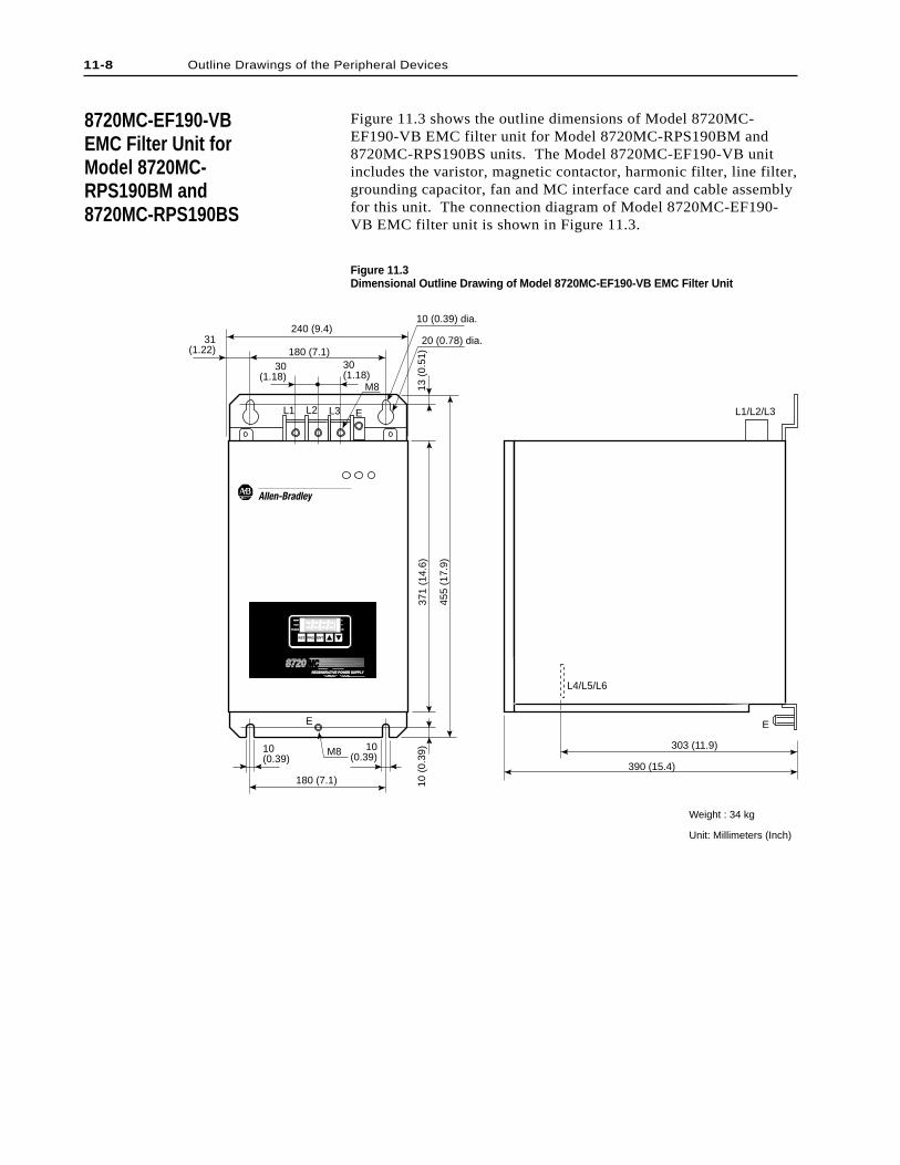
11-8 Outline Drawings of the Peripheral Devices
Figure 11.3 shows the outline dimensions of Model 8720MC-EF190-VB EMC filter unit for Model 8720MC-RPS190BM and8720MC-RPS190BS units. The Model 8720MC-EF190-VB unitincludes the varistor, magnetic contactor, harmonic filter, line filter,grounding capacitor, fan and MC interface card and cable assemblyfor this unit. The connection diagram of Model 8720MC-EF190-VB EMC filter unit is shown in Figure 11.3.
8720MC-EF190-VBEMC Filter Unit forModel 8720MC-RPS190BM and8720MC-RPS190BS
Figure 11.3Dimensional Outline Drawing of Model 8720MC-EF190-VB EMC Filter Unit
Weight : 34 kg
Unit: Millimeters (Inch)
10(0.39)
10(0.39)
10 (
0.39
)37
1 (1
4.6)
455
(17.
9)
180 (7.1)
M8
E
13 (
0.51
)
30(1.18)
30(1.18)
31(1.22) 180 (7.1)
240 (9.4)20 (0.78) dia.
10 (0.39) dia.
M8
EL1 L2 L3 L1/L2/L3
L4/L5/L6
303 (11.9)
390 (15.4)
E
REGENERATIVE POWER SUPPLYREGENERATIVE POWER SUPPLY
8720 MCMC
RST PRG ENT
READYREADY
FAULFAULT
PROGRAMPROGRAM kWkW
V
A
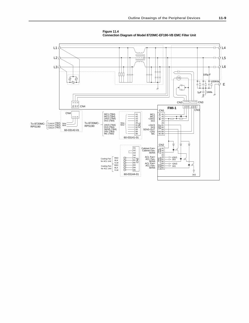
Figure 11.4Connection Diagram of Model 8720MC-EF190-VB EMC Filter Unit
+
+
L4L1
L2
L3
L5
L6
E
1 2 3
1 2 3 1 2 31 2 3
R1
S1
T1
CN3
CN3
CN
160-03141-01
60-03144-01
60-03142-01
CN2
CN
2
CN1
CN3
CN4
CN4
FMI-1 A1 A2 A3 B1 B2 B3
A1A2A3A4A5B1B2B3B4B5
A1A2A3A4A5B1B2B3B4B5
A1A2A3A4A5B1B2B3B4B5
A1A2A3A4A5B1B2B3B4B5
MC1MC2
+24V20V2
+24V30V3
SENS-OUT+24V
MC
Cabinet Fan+Cabinet Fan-
SENS
ACL Fan+ACL Fan-
SENSACL Fan+ACL Fan-
SENS
StripWire
StripWire
MC1 (TB4)MC2 (TB4)24V2 (TB4)0V2 (TB4)
24V3 (TB4)0V3 (TB4)SENS (TB4)24V (TB3)MC (TB3)
To 8720MC-RPS190
To 8720MC-RPS190
L1AUX (TB2)L2AUX (TB2)L3AUX (TB2)
COIL
MC
Ctrl
+24V
3/S
EN
S
+24VMC
FAN
3PO
WER
FAN
2PO
WER
FAN
1PO
WER
0V3
+24V30V3
0V3+24V3
100µ F
1µF 1MΩ
150KΩ
REDBLKYLWREDBLKYLW
Cooling Fanfor ACL Unit
Cooling Fanfor ACL Unit
Outline Drawings of the Peripheral Devices 11-9

11-10 Outline Drawings of the Peripheral Devices
End of Chapter
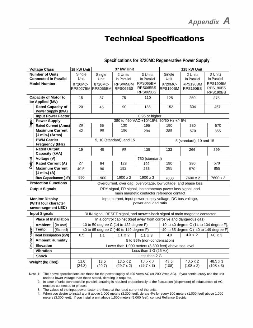
Appendix A
Specifications for 8720MC Regenerative Power Supply
Technical Specifications
SingleUnit
SingleUnit
SingleUnit
2 Unitsin Parallel
2 Unitsin Parallel
3 Unitsin Parallel
3 Unitsin Parallel
RPS190BMRPS190BSRPS190BS
RPS065BMRPS065BSRPS065BS
8720MC-RPS027BM
15
20
2842
19
27
990 1900 76001900 x 2 7600 x 2 7600 x 31900 x 3
40.5
0.5 1.1
6496
128 192 190285
570
570 855380
750 (standard)
45 90 135 133 266 399
6598
130 195196 294
190285
380 570570 855
0.95 or higher
5, 10 (standard), and 15 5 (standard), 10 and 15
380 to 460 VAC +10/-15%, 50/60 Hz +/- 5%
37
45
75
90
110
135
250
304
375
457
125
152
RPS065BMRPS065BS
8720MC-RPS065BM
RPS190BMRPS190BS
8720MC-RPS190BM
15 kW Unit Voltage Class
Model Number
Input Power FactorPower Supply
Inp
ut
Ou
tpu
t Voltage (V)Rated Current (A)
Protection FunctionsBus Capacitance (µF)
Output Signals
Input Signals
Ambient Temp.
Ambient HumidityHeat Dissipation (kW)
Elevation
En
viro
nm
ent
VibrationShock
Weight (kg (lbs))
Place of Installation
Monitor Display(WITH four characterseven-segment LED)
Maximum Current (1 min.) (A)
Rated OutputCapacity (kVA)
PWM CarrierFrequency (kHz)
Maximum Current(1 min.) (Arms)
Rated Current (Arms)
Rated Capacity ofPower Supply (kVA)
Capacity of Motor tobe Applied (kW)
Number of UnitsConnected in Parallel
37 kW Unit 125 kW Unit
192
-10 to 50 degree C (14 to 122 degree F) -40 to 65 degree C (-40 to 149 degree F)
-10 to 40 degree C (14 to 104 degree F),-40 to 65 degree C (-40 to 149 degree F)
In a control cabinet (kept away from corrosive and dangerous gas)RUN signal, RESET signal, and answer-back signal of main magnetic contactor
Input current, input power supply voltage, DC bus voltage,power and load ratio
RDY signal, FR signal, instantaneous power loss signal, andmain magnetic contactor reference contact
Overcurrent, overload, overvoltage, low voltage, and phase loss
288
5 to 95% (non-condensation)
Less than 1 G (25 Hz)Less than 2 G
Lower than 1,000 meters (3,300 feet) above sea level
11.0(24.3)
13.5(29.7)
48.5(108)
13.5 x 2(29.7 x 2)
48.5 x 2(108 x 2)
13.5 x 3(29.7 x 3)
48.5 x 3(108 x 3)
Note 1: The above specifications are those for the power supply of 400 Vrms AC (or 200 Vrms AC). If you continuously use the unit under a lower voltage than those stated, derating is required.
2: In case of units connected in parallel, derating is required proportionally to the fluctuation (dispersion) of inductances of AC reactors connected to phases.
3: The values of the input power factor are those at the rated current of the units.4: When you desire to install a unit above 1,000 meters (3,300 feet), derate 4% for every 300 meters (1,000 feet) above 1,000
meters (3,300 feet). If you install a unit above 1,500 meters (5,000 feet), contact Reliance Electric.
(In use)(Stored)
4.01.1 x 2 4.0 x 2 4.0 x 31.1 x 3

A-2 Technical Specifications
End of Appendix
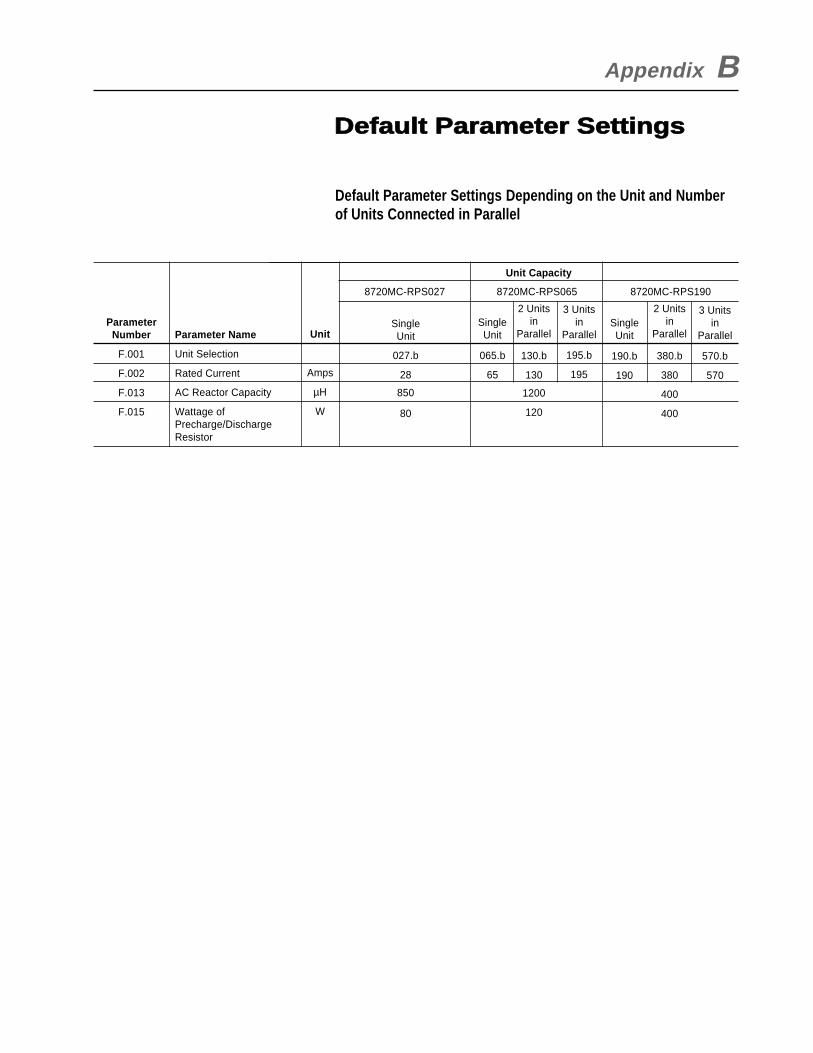
Unit Capacity
Default Parameter Settings Depending on the Unit and Numberof Units Connected in Parallel
ParameterNumber
F.001
F.002
F.013
F.015
Parameter Name
Unit Selection
Rated Current
AC Reactor Capacity
Wattage ofPrecharge/DischargeResistor
Appendix B
Default Parameter Settings
Unit
Amps
µH
W
8720MC-RPS027 8720MC-RPS065 8720MC-RPS1908720MC-RPS065
SingleUnit
027.b
28
850
80
SingleUnit
065.b
65
2 Unitsin
Parallel
130.b
130
1200
120
2 Unitsin
Parallel
380.b
380
400
400
SingleUnit
190.b
190
3 Unitsin
Parallel
195.b
195
3 Unitsin
Parallel
570.b
570
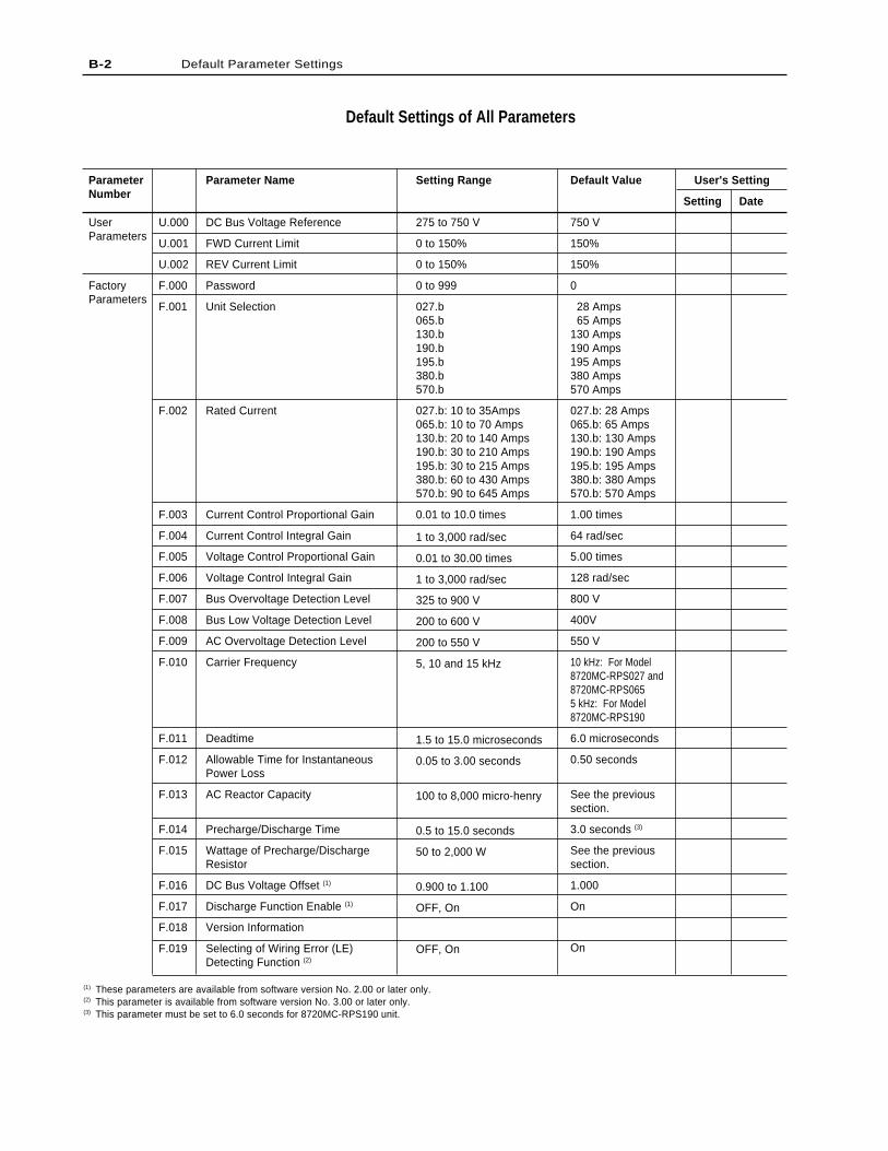
Default Settings of All Parameters
User's Setting
Setting Date
Default Value
750 V
150%
150%
0
28 Amps 65 Amps130 Amps190 Amps195 Amps380 Amps570 Amps
027.b: 28 Amps065.b: 65 Amps130.b: 130 Amps190.b: 190 Amps195.b: 195 Amps380.b: 380 Amps570.b: 570 Amps
1.00 times
64 rad/sec
5.00 times
128 rad/sec
800 V
400V
550 V
10 kHz: For Model8720MC-RPS027 and8720MC-RPS0655 kHz: For Model8720MC-RPS190
6.0 microseconds
0.50 seconds
See the previoussection.
3.0 seconds (3)
See the previoussection.
1.000
On
On
Setting Range
275 to 750 V
0 to 150%
0 to 150%
0 to 999
027.b065.b130.b190.b195.b380.b570.b
027.b: 10 to 35Amps065.b: 10 to 70 Amps130.b: 20 to 140 Amps190.b: 30 to 210 Amps195.b: 30 to 215 Amps380.b: 60 to 430 Amps570.b: 90 to 645 Amps
0.01 to 10.0 times
1 to 3,000 rad/sec
0.01 to 30.00 times
1 to 3,000 rad/sec
325 to 900 V
200 to 600 V
200 to 550 V
5, 10 and 15 kHz
1.5 to 15.0 microseconds
0.05 to 3.00 seconds
100 to 8,000 micro-henry
0.5 to 15.0 seconds
50 to 2,000 W
0.900 to 1.100
OFF, On
OFF, On
Parameter Name
DC Bus Voltage Reference
FWD Current Limit
REV Current Limit
Password
Unit Selection
Rated Current
Current Control Proportional Gain
Current Control Integral Gain
Voltage Control Proportional Gain
Voltage Control Integral Gain
Bus Overvoltage Detection Level
Bus Low Voltage Detection Level
AC Overvoltage Detection Level
Carrier Frequency
Deadtime
Allowable Time for InstantaneousPower Loss
AC Reactor Capacity
Precharge/Discharge Time
Wattage of Precharge/DischargeResistor
DC Bus Voltage Offset (1)
Discharge Function Enable (1)
Version Information
Selecting of Wiring Error (LE)Detecting Function (2)
ParameterNumber
UserParameters
FactoryParameters
U.000
U.001
U.002
F.000
F.001
F.002
F.003
F.004
F.005
F.006
F.007
F.008
F.009
F.010
F.011
F.012
F.013
F.014
F.015
F.016
F.017
F.018
F.019
B-2 Default Parameter Settings
(1) These parameters are available from software version No. 2.00 or later only.(2) This parameter is available from software version No. 3.00 or later only.(3) This parameter must be set to 6.0 seconds for 8720MC-RPS190 unit.
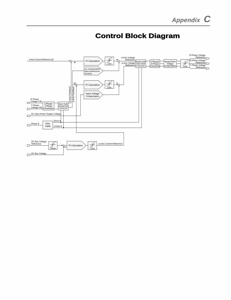
Appendix C
Control Block Diagram
d-Axis Current Reference (0)
R-Phase Voltage F/B
T-Phase Voltage F/B
AC Input Power Supply Voltage
Phase θSince θ
Cosine θ
DC Bus VoltageReference q-Axis Current Reference
Limit
Limit
Limit
Ramp
+
+
++
+
DC Bus Voltage
SineTable
3-Phase/2-Phase
Conversion
Static Shaft/Rotating ShaftConversion
d-A
xis
Fee
dbac
k
q-A
xis
Fee
dbac
k
d-Axis VoltageReference
q-Axis VoltageReference
Rotating Shaft/Static ShaftConversion
2-Phase/3-Phase
Conversion
Neutral PointVoltage
Compensation Limit
R-Phase VoltageReference
S-Phase VoltageReference
T-Phase VoltageReference
Input VoltageCompensation
PI Calculation
ωL Compensation(Non-interferenceControl)
PI Calculation
PI Calculation

C-2 Control Block Diagram
End of Appendix


Publication 8720MC-RM001C-US-P, Nov 01 © 2001 Rockwell International Corporation. Printed in Japan


![REGENERATIVE BRAKING SYSTEM IN ELECTRIC VEHICLES · REGENERATIVE BRAKING SYSTEM IN ELECTRIC VEHICLES ... REGENERATIVE BRAKING SYSTEM ... Regenerative action during braking[9]](https://img.pdfslide.us/doc/110x75/5adccef67f8b9a1a088c7cf0/regenerative-braking-system-in-electric-vehicles-braking-system-in-electric-vehicles.jpg)