Embed Size (px)
Citation preview

Report No. CG-D-73-78
FLAME ARRESTOR DESIGN REQUIREMENTS FOR
' • PROLONGED EXPOSURE TO METHANE/AIR,
II • AND GASOLINE/ AIR FLAMES
R. P. WILSON, JR. AND D. P. CROWLEY/ 4
I I"
DC
JAN 8 1979
FINAL REPORT I KSEPTEMBER 1978
Sw* Di nt is ovailable to the public through thedenal Technical Information Service,
_Springfield, Virginia 22151
Prepared for
U.S. DEPARTMENT OF TRANSPORTATIONUnited States Coast Guard
Office of Research and DevelopmentWashington, D.C. 20M0
79 01 05 013hS
m ,• .• - --

P9
NOTICE
This document is disseminated under the sponsorship of the Departmentof Transpoiuation in the interest of infomiation exchange. The UnitedStates Government assumes no Iability for its contents or use thereof.
The contents of this report do not necessarily reflect the official vwor policy of the Coast Guard; and they do not constitute a stidard,specification, or regulation
This report, or portions thereof may not be used ior advertising orsales promotion purposes. Citation of trade names and manufacturersdoes not constitute endorsement or approval of such products.
E

Techklicil Report Documentation Pager". Report No. c2 Go.rnmerat Acession N.e .
ITFlame Arrestor Design Requirements for Prolonged September 15, 1978Exposure to Methane/Air, Butane/Air ý,Gasoline/Air 6. Pe,..r -"4I Ircrl
10 P ..... • o~mn No.
RP.Wilson, Jr. _ .- D. 3. .ROWLEY
. aFrming Organzaton Name and Addres•.
20 Acorn Park 1 9,,9t o A.•.i€•,u ,,#..
Cambridge, MASS. 02140 V -.1p9 t 0r19LJWr. -1 _11.... V-V.•od Covered
12. Spon.o,,,it Agen., N.m. and Address G-DSA-I/TP44Department of TransportationU. S. Coast Gjard (G-DSA-1/TP44)Washington, D. C. 20590 14. Sponsoring Agency Code
is. Supplementary Notei.
Tests were performed in order to extend the empirical basis for evaluating thedesign of flame arrestors to the case of prolonged exposure to a stabiliEedflame for periods up to 30 ninutes. Both parallel plate arrestors and crimpedribbon arrestors, whose dimensions of passageway diameter &nd length had beenshown to be zargtral for arresting moving methane/air and butane/air flameswere tested. The resulto of the tests denovstrated that the design criteria(Maximumk- ) to withstand prolonged exposure to a stabilized flame are %,:lightlymore strinse'at than the criteria for quenching or arresting a moving flame.
17. Key W Arr ess Is. Di,tribution Srtatment
Flame Arrestor Flame Control Document is available to the publicFlame Arrestor Prolonged Flame hrough the National Technical Informa-
Arrestor tion Service, Springfield, VA. 2211I.Arre.ster
.9. Socuritir Clessil. (of this report) 20. Security Clsseif. (of this 0eo) .11. me.. of I~s 2. Price
Unclassified Unclassified 55
Form DOT F 1700.7 (S-72) Reprodurtir of completed oage authoti sod
J-- ,
- --- -A
I S
uu-4. d 0.•"
4' I I
E E 7
- 2" ""4 i i" Oi| • - ':: . •
20
[G
AtA
21 UA~~ S r~t~1 I*j AL u ~
~~~1 dca E ~-
.IN
amEs u 4~
"I i EE
4A a-O I S I S i i ~ i ~ ~ o
..........

TABLE OF CONTENTS
PAGE
I. BACKGROUND AND SUMMARY OF FINDINGS 1
A. Background 1B. Summary of Findinpg 3
II. EXPERIMENTAL METHODS 5
A. Test Facility Descxiption 5B. Instrumentation 8C. Gasoline Vapor Supply System 12D. Operating Procedure 15E. Gases Tested 18F. Flame Arrestors Tested 18
Ill. PERFORMANCE OF ARRESTORS UNDER PROLONGED 23FLAME EXPOSURE
A. Resiults 23B. Conclusions 32
APPENDIX A - Detailed Results of Heat-Up Tests 36
AP'PENDIX B - Determination of Gasoline Vapor Composition 43Variat ion with Time
REFERENCES 47
Acknowledgement
Lieutenant Michael Flessner of the Marine Safety Branch,
Division of Applied Technology, Office of Research and Development,
United States Coast Guard contributed substantially in both the
planning and interpretation of the experiments reported herein.
fi
1. BACKGROUND AND SUMMARY OF FINDINGS
A. B~ackxround
Tests were performed in order to extend the empirical basis for
evalitating the design of flame arrestors to the case of prolonged
exposure to a stabilized flame for periods up to 30 minutes. Previous
work by Arthur D. Little, Inc. under Contract No. DOT-CG-42357A
addressed the design criteria fcr stopping high-speed flames which canaccidentally develop in cargo vent pipes. When flame passage through
the arrestor is prevented, the flame does not necessarily extinguish,
and in many instances will stabilize at the face of the arrestor where
it is supplied with fresh mixture. This situation continues, with
gradual heat up of the arrestor and other componerts in proximity fto the flarie, until one of three events occur:
(1) The supply of fuel or mixture is sht't off by an noperator;
(2) The flow rate of mixture is increased until the
flame is expelled from the vent piping;
(3) The flame passes through the arrestor, either due
to arrestor heat-up or en gross thermal failure
(melting of arrestor sections).
The central issue can be stated as follows: Even if the arrestor
design is adequate to stop a propagating flame, what additional
design constraints must be placed on the arrestor, in order to prevent
flame passage during or after heat-up? Two possible criteria
come to mind:
H LI
(i) The passageway diameter must be smaller if the flame is
to be controlled after tae arrestcr heats up. Basically,
the flame speed will increase as the unburned mixture
temperature increases and a. less heat is lost to the
passageway boundary zone because the walls are warmer.* -1/2 *
The result can be expressed as DH 1 T , where DH is the
hydraulic diameter of the passageway and T is theu
temperature of the unburned mlxcure (see reference 4).
(ii) The metal thickness and thermal diffusivity must be
adequate to distribute the heat flux received from the
flame ard to prevent mwlting. Assuming that arrestor
failure occurs whenever the temperature within the
arrestor body exceeds some critical value, the arrestor
must be designed to keep the bottom portion cool for as
long as possible.
In the transient during which a pronigating flame attempts to enter
the passageways of a flame arrestor, the metal chickness and thermal
diffusivity do not affect whether the flame Is stopped. (For example,according to tests, plastic arrestors have the same effectiveness
as metal arrestors,) This result has been explained by the argument
that the flame loses heat to the cold gas next to the walls rather
than to the walls themselves. Once the flame stabilizes and begins
to heat up the arrestor, the thermal properties of the mctal come
into play. The interior surfaces of an aluminum arrestor of low mass
will reach a greater temperatu:e in steady-state -han those of a
ceramic or plastic arrestor, and thereby heat up the gass which passes
through the arrestor (which favors flame transmission).
Prior work on extended exposure of arrestors has been reported
by Bolts et al(1) and Rogc'qski ani Ames. (2) Bolta et al(l) could not
induce flashback in 30 minutes through a 1/2-inch thick crimped ribbon
arrestoin of 0.12 cm crimp height, using propane/air mixtures. This
2
arrestor was made of stainless steel and reached an equilibrium
temperature of 708*F on the hot side within 5 minutes. Doubling the
arrestor thickness (to 1-inch) decreased ths wall temperature to 477°F
but doubled the equilibration time (to 10 minutes). Obviously the
flame was stabilized by this thicker arrestor. Doubling the approach
speed of the flammable. mixture reduced thR hot side temperature, as
expected.
Rogowski and Ames(2) tested crimped ribbon arrestors of smaller
crimp height than Bolta et al (.05 and .10 cm), longer length
(1.5 Inches), and higher thermal diffusivity (cupro-nickel brass).
Since all of these factors assist heat extraction, it was not surpris-
ing that Rogowski also found no flame passage for propane/air.
However, when tests were performed on ethylene, which has a .15 cm
theoretical critical diameter at normal temperature (40% smaller than
propane), the arrestor failed after 5-15 minutes. Pyrometer readings
of the hot side temperature indicated 1300*K, and (according to the* -1/2
D * T rule of thumb) this temperature would have reduced theH ua 1/2flame quenching diameter by a factor of (1300'K/30 0 K) - 2.1, or
to .071 cm, Since .071 cm 13 comparable to the crimp height of the
above arrestors, it is not surprising thao flame-through occurred.
B. Summary of Findings
1. The parallel plate arrestor , whose dimensions (L - 0.5",
D - .045") had been shown to be marginal for arrestingH
movi•ig flames (e.g., will arrest low-speed flames but not
high-speed flames) did not control stabilized flames
during heat-up test using butane/air or gasoline vapor/air
for periods longer than epproximately one to ten minutes.
However, it controlled methane/air flames for periods
averaging 25 minutes.
3
------------------------------------------- -,-.. ..

2. The crimped ribbon arrestor, whose dimensions (L ..375",
DH .031") had been shown to be marginal for arresting
moving methane/air and butane/air flames, failed to control
stabilized flames from those same mixtures for periods
longer than approximately one to three mirutes on the
average. However, it successfully controlled flames from
gasoline vapor/air for periods of 30 minutes.
3. Based.on findings 1 and 2, the design criteria (maximum D)
to withstand prolonged exposure to a stabilized flame are
slightly more stringent than the criteria for quenching
or arresting a moving flame.
4. Thermal equilibration occurred for the parallel plate
arrestor and crimped ribbon arrestor in 7 minutes and
1 minute, respectively; this response time of course
depends on thermal properties (conductivity, heat
capacity, thickness of elements, depth of arrestor, etc.).
In practical situations, the arrestor heat-up time will be
available for mixture shut-off, dilution, steam sntffing
or other corrective measures. Therefore the arrestor mist
be designed to keep the metal temperature in the bottom
layer of the arrestor below critical levels as long as
possible.
5. Flame passage occurred at the following values of
arrestor metal temperature at the center-bottom of the
arrestor: 770 + 170*F for methane/air, 730 + 100*F for
gasolinc vapor/air, and 460 + 40*' for butane/air. These
temperatu..as and margins encompass the results of Table 3
for both arrestor types.
Flame speeds 2-16 ft/sec.
4
II. EXPERIMENTAL METHODS
A. Test Facility Description
A complete descriptioi of the test facility in which heat-up
tests were performed is given in Wilson and Crowley, and is
summarized below. No modifications were made to the faci. Lty except
for the addition of a temperature recording system for monitoring
flame arrestor temperatures during tests.
The temperature recording system consisted of a 12-point Leeds
and Northrop recorder Model W, several sets of chromel/alumel
thermocouples and appropriate feed-through connections.
The flame arrestor apparatus consists of a 6" cylindrical testsection, controls and instrumentation. A controlled flow of a
specified flammable gas mixture is a1.lowed to pass through the test
section (containinrg the flame arrestor) and is ignited at the start
of the test by a spark discharge downstream of the arrestor. The
resulting combustion wave accelerates toward fJe arrestor. For heat-
up tests, the fuel/air mixture velocities were adjusted to acbieve
continuous burning at the arrestor following normal upstream flame
propagation. The rate of upstream flame propagation had to be low
enough to achieve flame stabilization rather than quenching at thearrestor. Low velocLy flame propagation was achieved by operating
without an orifice restriction at the test pipe exit (the 18-inch
pipe extension was used). The performance of the arrestor was auto-
matically recorded. A pl-otograph and schematic of the apparatus are
given in Figures 1 and 2, respectively.
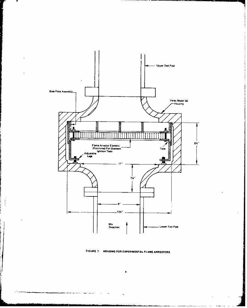
Referring to Figure 2, the test section consists of 6-inch dia-
&,eter vertical pipe, 17-feet high, with a flame arrestor housing
located midway up the pipe. Provisions for both mixture preparation and
pressure relief are at the base of the pipe. The actual flame arrestor
5

WI
0,• i ,
Figure 1'. Facility for flame control testing
6

Dilution and Exhaust 13000 CIMI
Optical Port No.1I
Recorderoptical Port No. 2 o
Pressure Transducer
Optical Port No. 3 ---- 0-- ptical Port No. 4 OfO
Flam ArrstorSwitc'*Solonoid ValveF'anw Orrestn
HousinggDVM
Test Pipe 6' Dia. C) Selector Switch
PIGUAI 2 FLAll AxESO TETAPPAATU
Optial Prt N. 2

device is located midway up the vert~ical pipe section in the housing
shown in Figure 3. it was not necessary to cool the housing despite
30 minute exposures to stabilized flames. For realistic simulation
of cargo vent conditions, cooling would not be appropriate in any case.
Fuel gas was supplied to the test section through a perforated ane-
inch diameter capped tube located in the center of the Tee at the base
of the test pipe. Tests of conczentration decay showed that complete
mixing was achieved 1.5 ft above the nozzle.
Butane, methanie, and gasoline vapor were used during the program
discussed below.
B. Instrumentation
A summary of the instrumentation is giver, in Table 1. An optical
detector at port 3' was used for detection of flame-through at the
arrestor. The optical detector in port 3' was also connected via a
power amplifier to the fuel solenoid valve. In the event of flame-
through, the fuel solenoid would automatically shut off.
In order to measure arrestor temperatures during heat-up tests,
thermocouples were installed using a spot welding method at specific
locations on each arrestor. The thermocouples were 18" long, 30 gauge
chromel/alumel thermocouple wires, electrically insulated using double
hole high temperature ceramic tubing.
In the parallel plate arrestors, nine thermocouples were installed
in three slots milled out of three arrestor plate elements, as
k illustrated in Figure 4. The arrangement of the slots was such that
temperatures could be measured at three planes (depths) in the
arrestor: .062", .25", and .50" from the side of the arrestor facing
the flames. After installing the thermocouples in slots, the elements
were reassembled In the arrestor and the thermocouples were connected
to a Leeds and Northrop multipoint recorder.
8
8 Upper Test Pipe
Base Plate Assembly-
Hoasing
Flame Arrestor E lement(Positioned For Upste.m Tp
Ajsal Ignition TestsS.AdjustableLegs
T
MixDirection ,- Lower Test Pipe
FIGURE 3 HOUSING FOR EXPERIMENTAL FLAME ARRESTORS
9

Table 1
Summary of Instrumentation
Variables Measured Measuring Instrument Accuracy
Air tlow rate Meriam 50 MY 15-4 Flowmeter with + 0.5%
Meriam A844 Manometer
Air temperature Omega CAIN-116G-24 Thermocouple + 11F
Gas flow rate Meriam 50W201F flmnuter with + 0.5%
Ellison IN Manometer
Gas temperature Omega CAIN-116G-24 Thermocouple with + 1F
Dana 4470 Digital Voltmeter
Flame speed ADL fabricated photodetector 5kof thesystem with EG&G HUV 1000 1 valuesensors - 3 units
Flame-through event ADL fabricated photodetector Positivesystem with EG&G HUV 1000 B detectionsensor - 1 unit
Test chamber pressure Kulite XTS-190-200 pressure + 0.5 psitransducer & ADL fabricatedoperational circuitry
Spark ignition event CEC 5-125 Oscillograph UnspecifiedGas Solenoid valve Recorder 8 channelshut off event
Photodetector eventsignals
Pressure transducersignals
Barometric pressure National weather service - local Unspecifieiarea
Arrestor Temperatures Chromel/Alumel thermocouples + 100F
10

Assembly rods
c .•- Thermocouples (9)
Element A TC4 7c, rC Thernocouple Location
SI T - Top plane
EenBI T's Tc2 M - Mid plane-- B - Bottom plane
Element C WI T:S j* 4 i _ _
-... : -- Parallel plate elemant stack
Arrestor plan view
Element A _ r -0 0 - .
Slots: .032" deep
Elemen.t B 0 .062" wide
4v-0 y:Plates: .13" long
.5" highElement C *o -T s 1048" thick
Holes for assembly rods
Details of thermocouples slot location
Thermocouplespot welded to ceramic
plate, in slot insulator Section A-A
Details of thermocouple insulation
Figure 4: Thermocouple Location and Installation
Details for Parallel Plate Arrestor
In the crimped ribbon arrestor the thermocouple assemblies were
spot welded at the top and bottom surfaces of the arrestor in three
xadial positions (1", 2", and 3"1 radius) as illustrated in Fig~re 5.
An eight channel recorder (CEC Model 5-124) was used to record
signals from the instrumentation. The three optical detectors and
the pressure detectors were connected directly to the recorder. The
signal from the flame-through detector was, as mentioned above,
connected to a power amplifier to shut off the fuel solenoid. This
signal was also connected to the recorder so that the flame-through
event could be recorded. A signal from the ignition switch was also
connected to the recorder to record the existence and duration of
the spark discharge. During the conduct of heat-up tests, the standard
recording system was operated only long enough to record the upstream
propagation of the flame front and its stabilization at the arrestor.
The multipoint recorder was used for the entire test period, in
addition to recording temperature histories, time for flame-through,
and top and bottom arrestor temperatures at flame-through were also
recorded.
C. Gasoline Vapor Supply System
A system was set up to produce steady state vaporization of
gasoline liquid for supplying gasoline vapor to the flame arrestor
test apparatus. The system, shown schematically in Figure 6, consisted
of a heated packed column containing approximately 1-gallon of liquid
gasoline and a heated nitrogen gas supply. The system was designed
to saturate a 1 CFM flow of nitrogen with gasoline vapor, producing
a vapor mole fraction of about 0.5 depending on nitrogen temperature.
During the 30 minute test duration, the vapor composition varied
with time, as discussed in Appendix B. The lighter fractions appeared
first, with stabilization after about 5 minutes.
12

"X - Top thermocouples) 0 - Bottom thermocouples
TCZ
\ •7.
ThermocoupleThermonctoue 2 Hole ceramic insulator
Fibrous ceramic spot welded
SDetails of installation method
Figure 5: Thermocouple Location and Installation
Methods for Crimped Ribbon Arrestor
13

II
JIA
II
14
D. Operating Procedure
The operating procedure described in reference (3) waE modified
slightly to permit continuous burning of the gas/air mixtures at the
arrestor. The procedure for testing with methane/air and butane/air
mixtures differed from that used for testing gasoline/air mixturep.
In conducting teats using methane/air or butane/air mixtures,
the following sequential procedure was used:
(1) A safety check of the test site was made which included:
-- Access to fire extinguishers;
-- Wearing of hard hats, glasses and ear protection;
-- Locating danger warnings and restricted area barriers;
-- Turning on flashing red lights in critical area of the
test site; and
-- Turning on the system exhaust fan.
(2) A check of the optical detector and pressure detector
battery condition was made.
(3) The main Power Switch was turned on.
(4) The recorder power and optical, pressure detector power,
switches were turned on ignition power and DVM power.
(5) The selection of upper ignition source was made.
(6) The arrestor element was installed in the housing and
the housing cover secured.
(7) Butane supply and inline heaters were activated and
allowed to come to temperature equilibrium (approximately
1000F and 120*F, respectively). For methane, no in-line
heaters were used.
(8) The air supply blower was turned on and adjusted to
achieve the appropriate flow rate--corrections to the flow
rate for barometric pressure and air temperature were
made.
15

(9) Fuel tank valve, fuel shut-off cocl: and solenoid valve
were opmed. This was followed by an adjustment of the
throttling valve until the appropriate fuel flow rate
was achieved. Corrections for barometric pressure and
fuel gas temperature werE also made.
(10) The gas/air mix was allowed to flow for 60 seconds.
(11) In moderately rapid sequence:
-- The multipoint temperature recorder was turned on;
-- The high-speed recorder was turned on-(to 1 inch/sec
for adequate trace resolution);
-- The ignitor was energized-followed immediately by
combustion;
-- When the passage of the flame front and stabilization
of the flame at the arrestor were ascertained from thesystem recorder trace, the high-speed recorder was shut
off. (At this timwý, optical detectors 2, 3 & 3' were
also removed from the test pipe as a precaution against
overheating.)
(12) The -- tltioir': recorder was observed for temperature
histo-iev of the arrestor elements. recific note was made
o. the temperature at which flame-througt occurred (if
at all). Flame-through was noted both aurally and by the
indication of the operation of the autcmatic fuel shut off
vaIve (triggereel by flre-thzough event).
(13) Cf 'lume-throagtt occurred, the -ir blower was shut off to
quench the flame. Otherwise the heat-up test was continued
for a period of 30 minutes at which time the manual fuel
valve and the air blower was allowed to continue running
to assist in the system cool down.
(14) The temperature recorder was shut off and the recording
e.camined for heat-up histories.
16
.....------ -.--- - I I [ --- .. ... ".......

For gasoline/air mixtures the procedure was essentially the same
as for methane/air and butane/air up to step 6, wheteupon the procedure
was as follows:
(7) The air blo%.er was turned on and adjusted to achievethe appropriate flow rate.
(8) A five gallon supply of gasoline was placed in the gasoline
vapor converter reservoir. (The quantity was sufficientto serve several tests).
(9) The gasoline supply, nitrogen and in-line heaters were
activated to achieve an equilibrium temperature ofapproximately 120'F.
(10) The fuel valve solenoid was opened and the fuel circulation
pump was turned on.
(11) After approximately 30 minu..es the weight of the gasoline
reservoir was measured.
(12) The nitrogen gas valve was opened and adjusted to 3.5 CFM.
(13) AftPr a period of 2 minutes in moderately rapid sequence
-- The multipoint temperature recorder was turned on;
-- The system recorder was turned on (I inch/sec);
-- The igniter was eno.rgized--followed immediately by
combus t ion; 4
-- When the passage of the flame front and flame stabilization
at the arrestor were ascertained from the high-speed
recorder trace, the recorder was shut off and optical
detectors were also removed (as a precaution against
overheating).
(14) The temperature recorder was observed for temperature
excursions of the arrestor thermocouples.
17

(15) The heat-up test was alloweR to continue for a period
up to 30 minutes at which time:
-- The temperature recorder was shut off;
-- The nitrogen gas was turned off. The air blower
was allowed to continue running to assist in system
cool down; and
-- The fuel valve solenoid was shut off.
(16) The gasoline reservoir was reweighed and an average
vaporization rate for the test was determined.
(17) The multipoint recorder was examined to determine
temperature histories.
E. Gases Tested
Gases tested during the heat-up tests were as follows:
(1) Methane, C.P., 99.0% minimum purity, gas/air mixture
equivalence ratio * 1.1.
(2) n-Butane, C.P. 99.0% minimum purity, gas/air mixture
equivalence ratio * 1.1.
(3) Gasoline vapor: Mobil .egular, Mobil Regular No Lead,
Exxon High Test, evaporated at approximately 120OF
through a 22-in high packed column using nitrogen as
carrier gas. Approximate vaporization rate 0.4 - 0.6 ft /
min, gas/air mixture approximately 3 percent by volume.
During the 30 minu .e test period the vapor composition
varied with time Ls discussed in Appendix B.
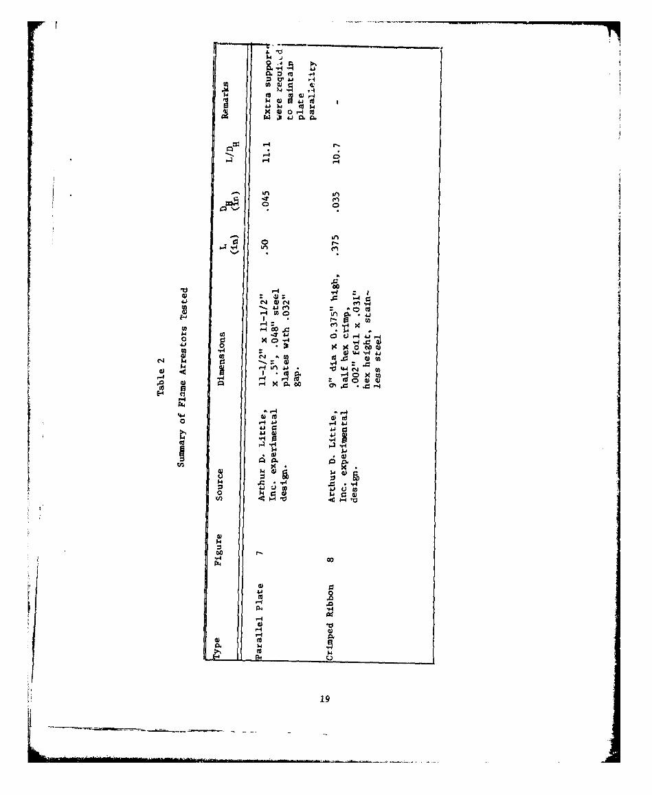
F. Flame Arrestors Tested
Two arrestors were tested for prolonged exposure to flames: a parallel
plate arrestor of L - 0.5 in, DH - 0.045 in (.032" gap); and a crimped
ribbon arrestor of dimensions L - 0.375 in, DH - 0.035 in. Table 2
gives detailed dimensions and Figures 7 and 8 display the arrestors.
18
494
4) 0 r-4 t
0.4 44n(
4) 2: -4
'410
r 0-4 00 Ap -* 450 Q r
0 ,.x J V4
*0f 0n (Vo 1*HX00
4-j cc 0
0 ý4
'v4.1
4.1V0
0 k0
r40
H ciHa
19
A t th 1) 1 lii II
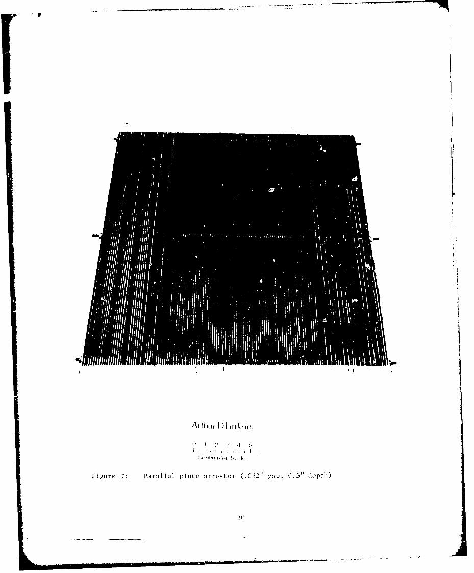
Figure 7: PatraLle1 plate arrestor (.03-2" gap, 0.5" depth)
20

I -1
"-4
'r-I
a)
''2 1.

During previous studies (reference 3), these arrestors were found to
have marginal dimensions (sufficient to arrest low-speed flames but
failing to arrest high-speed flames).
22

III. PERFORMANCE OF ARRESTORE UNDERPROLONGED FLAME EXPOSUJRE
A. Results
Except f or methane/air mixtures, the parallel plate arrestor iailed
to control flames during heat-up after periods ranging from approximnately
one to 10 minutes. The arrestor successfully controlled methane
flames for an average of 25 minutes. The crimped ribbon arrestor
f ailed to control methane and butane flames after a period of between
approximately one to three minutes. However, the crimped ribbon
arrestor successfully controlled gasoline flames for 30 minutes. A
summary of the tests results is shown in Table 3. Data from the
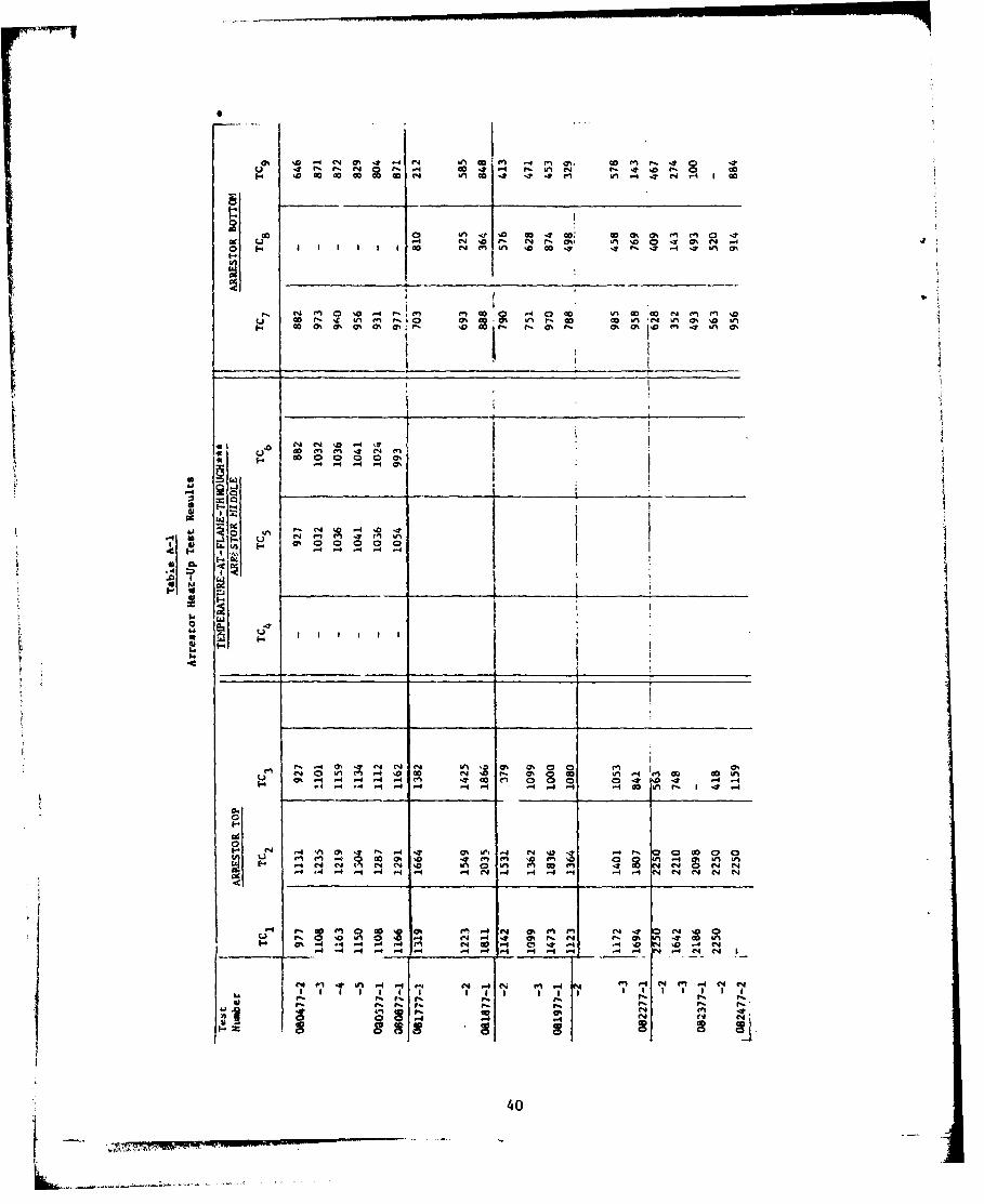
indiidul het-u tess ae litedin TbleA-1 f Apendx AAs can be seen from Table 3, the average temperature gradient
across the crimped ribbon arrestor was in general significantly higher
(by a factor of approximately five) than that of the parallel plate.
This is attributed to the difference in thermal properties of the
arrestor materials, dimensions of the arrestor elements and heat
conduction path of the two arrestors. Table 4 lists dimensions and
the estimated thermal properties of the two arrestors.
Figures 9 through 14 Illustrate typical time--temperature
histories of the top of the arrestors (facing the flame) during the
heat-up tests. The figures show histories of the thermocouple that
recorded the highest temperature during the tests.
During post-test visual observations of the arrestors, it was
noted that the central. area (approximately 4" diameter) of the crimped
ribbon arrestors appeared to be more heavily oxidized from flame
exposure than the remaining (9" diamieter) area of the arrestor.
23

+11 +1 4
-O .. 0 0
4, 4, +i , 4,.1 ÷*1 s •i
00 'a o 0o -o
o OD
IV,=
S~~ 4 5. 0 a
o o.00 0
o, o" 10 No 0k u
O2 ?4
,, iS P2e -
H H H h

Table 4
Physical amd Thermal Properties of Arrestors
? roprt _es Arrestors -
Crimped Ribbon Parallel Plate
Material Stainless Steel Cold Rolled Steel
Arrestor Element Thickness (in.) .002 .04f,
Arrestor Elerwnt Length (in.) .375 .50
Thermal Coniuctivity (Bcu/hr/ft*F) 8-12 26-36
Specific Heat (Btu/lbm-*F) .1 .13
Density (lb/in3) .28 .28
tI
25
... ........

00
$4
*144
-tot
0)
0.E6-4
P-1 r4 V .1
266
0 i5 711

Go
LA j00
* cn
4) 0
I 0
w o"
00
wo "m
0n 0
(A Of- el
$.i *27

I.~
OW 00
/Conojq4-mT
40
0 Al
u( 4 )1- '
0 1
o1 >.41)
~~C14
41 0
00
04 0 00
-.4 Z 3
CD C) D C
o0 0 0) 0 0 0 0o- 0 0 0 0n 0T 0 0 0
28

to0
00
41 0a
1.r- 4 w
4~12
"-r4
04 .0 0
0 0
4 1-
0-m 0 0 041 a 01
-~' 4 ) 441
a 0a
:1 -19

0
C-0%
0~
u0
00
E-4
00
- I.
6 .0 a 0.0l 0.i 4
.441l
300

A.
a, 0)
-w
I.r-,4 IC C
toi i k
IN 0
r444
4-i44- C)
Ai ýe4 = , % 0Qm 0 c"I 1-4 4
,.4H (1- 0-' 000
4)4' 4 K1
ci.
Cu 0 0) 440
0.ii 0 E-4 4o~x-H0) co
on 0 0 W0
(a,) duil

This suggests that the flames during the tests were concentrated
in the center section of the crimped ribbort arrestor. Maximum
temperatures at the top of the arrestor also indicate this effect;
i.e., thermocouple No. 3 (located at 3" radially from the arrestor
center) was generally cooler than the other two thermocouples (see
Table A-1, Appendix A). The localized flame effect was not visually
obvious for the parallel plate arrestor presumably because of the
generally lower maximum temperatures of the arrestor and the higher
thermal conductivity. However, thermocouple No. 2 (located in the
top center of the arrestor) indicated generally higher temperatures
than the other two top thermocouples (see Table A-1, Appendix A).
Since a 6 mesh, .030" dia. wire screen used to help support the
top of the crimped ribbon arrestors during the tests, heat-up tests
were performed to determine if the screen effected the arrestor
performance, using gasoline./air mixtures (3% concentration).
The results of the tests are tabulated in Table 5 and are plotted
in Figure 15. The results show that although in the test with the
screen the arrestor exhibited a slight heating delay, overall
performance of both arrestors are similar. That is, thermal stability
L was reached in each arrestor (differences in maximum temperature were
within normal variances) and both successfully controlled the flames
for 30 minutes.
B. Conclusions
1. The parallel plate arrestor, whose dimensions (L =0.5",
D =.045") had been shown to be marginal for arrestingH
moving flames (e.g., will arrest low speed flames but not
high speed flames) did not control stabilized flames
during heat-up test using butane/air or gasoline vapor/air
for periods longer than approximately one to ten minutes.
However, it controlled methane/air flames for periods
averaging 25 minutes.
32

Table 5
Results of Tests to Determine the Effect of 6 Mesh,.030" dia. Wire Screen on Arrestor Performance
Arrestor: Crimped Ribbon, L - .375", DH - .035"
Gas Mixture: Exxon High Test, 3% concentration
Test Conditions: Downstream ignition, no orifice,mixture velocity approximately 2 ft/sec,run up length 68-1/2"
Test with Screen Test without Screen
Test No. Time Top Bottom Test No. Time Top Bottom(min) Temp Temp (min) Temp Temp
(OF) (OF) (OF) (OF)
083177-1 0 66 66 090177-2 0 88 88
3 169 - 1 165 -
6 204 - 1.4 1050 -
6.5 208 121 2 1360 -
7.0 690 - 3 1730 370S8 1630 870 4 1790,
10 1800 102C 5 - 640
15 1910 1050 8 1810 -
20 1900 1040 10 1780 780
25 1880 1020 15 1735 780
30 1830 990 20 1740 800
25 1740 80030 1740 800
33kL_

td4 0 0
44 4. 0
r-4
*0)
41
0H
'4-4
oS T 0 0 0o 010N r 4 0- 0- 0- -4
(a. 0ma
03

- - W
2. The crimped ribbon arrestor, whose dimensions (L .375",
DH =.031") had been shown to be marginal for arresting
moving methane/air and butane/air flames, failed to
control stabilized flames from those same mixtures for
periods longer than approximately one to three minutes
on the average. However, it successfully controlled
flames from gasoline vapor/air for periods of 30 minutes.
3. Based on findings 1 and 2, the design criteria (maximum D)
to withstand prolonged exposure to a stabilized flame are
more stringent than the criteria for quenching or stopping
a moving flame. However, the reduction in DH required for
a stabilized flame below that required for a transient
flame does not appear to be large.
4. Thermal equilibration occurred for the parallel plate
arrestor and crimped ribbon arrestor in 7 minutes and
1 minute, respectively; this response time of course
depends on thermal properties (conductivity, heat
capacity, thickness of elements, depth of arrestor, etc.).
In practical situations, the arrestor heat-up time will
be available for mixture shut-off, dilution, steam snuffing
or other corrective measures. Therefore the arrestor must
be designed to keep the metal temperature in the bottom
layer of the arrestor below critical levels as long as
possible.
5. Flame passage occurred at the following values of
arrestor metal temperature at the center-bottom of the
arrestor: 770 + 170'F for methane/air, 730 + 100*F for
gasoline vapor/air, and 460 + 40*F for butane/air.
35

APPENDIX A
DETAILED RESULTS OF HEAT-UP TESTS
36

IV
04 F 00 FtV ý6 D
N4 0 '0*ý 0 61% 0% 1, %a'
--3
W - ~' b ~ M r4 I4 C4
00%r. -IN 4 1 0 2" s0 ~I * sv I' .
- $ 0 I~ 0 % *0 0 ~ . 0 0 04 0.. 0 0..d
6J -A-mmrAt-W m r W PA
Cu
m en C4 CI in C C" C C
w C
00 j 300 00 .0 0 40)0
..i .4J ~. . . 41 5( 4* f. 4144 J
a;1 4- a; - 4oz m m N 0 m 0 v " Q a 0 q
9L. a, CI 0. 10
-r% 10 a; 0 a; a; a ; *- C 4 'l ~ l *el It
go 94 fn-, 41w 1 4 1 4 . . U 0-4
_ 44 4 437

on An C4 ao~ , on r.0% .4 OD on r-M on U
U A . 0 Ln 47% 10 0' 03 CNI on n C4 00 .4m- m C- q .- oa -~ LA -A 0 10 on If 4 U0U
00m01 I.-r UN
,-.~~- on on 0 C40 Iý go 14 U , U . 0 14~to, 4 -0 P, m ~ a 4 .'t mV M
00 0n M4 r40 0z NOD 'c 0I
-I on on -n M 'T In.0 en A t, .4-. 4 I I 4 I N .0 0 1 0 %04' r. - N 0 N
U~C .1 It .4rNN N
on w 10 a o-4-4 .M -in oO
0 4- in on (N u I I Io
m ~ C4 N N N N N
'r ONLo JD V0 g% ' -
on v i A9i a -O
4.' n -4o
4..p m__ __ _ C4 IT o
o--
CIO' , 4t % N N ,N' '
Il'.4W 40 '0 N . 0 l U 38

H I. ~ MN 1K N 1
~ p I n 0-f In ,.ý Ln P4 (ND
(N 0% Nf yo .
91IU4 u IM I IU 1 S.4
~~..-4. 00 0 00 00 00000A Q3 2z ZO 9 320 A 33232m3 z
COD.~. CC '0 0 0 ''0 '0 ' '0. '0 OD CC OD ' o CC '0 '0 co,o go C 00 000 0 00 00 0
SILElow t v. .~ II ( N ( 'J ( I ( r A ( ~PC2 ~ ~_ _ _ 2 2'
000 000 0 0 0 0
A. .. A. A. A. A. -1 C-4 C, 4 -4 (N4. e4 4 .
77. ~14 - .4~~ ~S S El ~ U~ '0~ W
Q 4 ~ 41 5414 4w,
10 0 0 0
0 0I' Ni
39 I n w% L ' n n I e
r- In &4 r- 0% -t '-4 N . 4 0, . 0 40al) .044 ?.M' S- -1 40 0 0
H I d r in 'D GO -~44 I .
00 0, 'n (no .~j0 4vl IR .00%c 6 (4 0% a t L 00 0 4 N '1 % 0%' 0~ 0040 r- r- 0 .4n T t
4 -
P6 t i . 0m 0% 0% 0% 0%4 a00 % 4 % 4 0 %I0 4
.0 - 4 N4 -'
P. .4 0 4 N N An 'a 0% a% 0 0 ~ INO4 a ' LA m 0.0 .0 wA c4 a ,4 'M Goa0w
-%'4 .-4 .- f -4 .- 1 CA c4 0l 0 T '0 4-*-4.- 4 '4 ý4 24 -I -1 14 0 n4 . ý
I. N j *A Ch 4 % .4 1 0% uIA -4 N '0r CD 0o 1 5 00V) u. m-4- D A r 4 ' l. n W
rl ~ ~ ' 2 a n D 4 N 4 .1 atr N0% -4 No N4 '0 "~ 0o CIN .01 41 10 QN
4 4 - -4 .4 1- ý4 -4 -4 -- 1 4' ý4 - - " .t
-4 -4 -4 -4 -- 4 44 -4 -4 en 4 -4M -4 N . 4
IA 4
40 N

,1r 4
z . c
-IA-
.x 0-t A
0 ý4 -1 .4Lo ý2 .*I . .
LJU Ný 4f N4 ý4 ý4 -4
&M U) U U)%
44 00 00
0t .;
0 od 44 0 01 w
4.44
4)-4J3 ) ~ I u~u
E U)-W C40)~
~ U)~U)41

I in N4 44 '40
4.,i
44 6
.4 (.5 C484841
it5 10 0 4~
a 4-' 41
-4 co 4~ A4.8
'0 .enUV Vt
-4 Q 41
*~~c 4~ *4 . *0 5. 1 4.
H~ 0~ 4 IVIw .44.
41 4
ý414 -48.4-48.44~
IA .95 4408 SA 4
c.o. 4
-- 4 '-9 42
ME '4 - .
APPENDIX B
DETERMINATION OF GASOLINE VAPOR COMPOSITION VARIATION WITH TIME
Gas samples were taken from the outlet of the gasoline vapor
converter at various time intervals over the 30 minute operation of
the converter. The samples, obtained using a flow-through extraction
method, were subsequently analyzed using standard gas chromatography
(GC) procedures. Converter operating conditions during the test were
similar to that during normal operation for arrestor heat-up tests;
that is. gasoline temperature 120*F, gasoline circulation rate 275 ml/
min, nitrogen gas temperature and flow rate 120 0 F and 3.5 CFM,
respectively. During the test, the vaporization rate was approximately
40 gm/min average over the 30 minute period. (In prior tests over a
5 minute period, the vaporization rate was greater by about a factor
of four because of high volatiles evolved in the early phases--seereference 3. )
Gas vapor samples were taken at intervals of 1, 3, 10 and 30
minutes during the test. Analysis of the liquid gasoline was made
before and after the test. The gasoline tested was Exxon High Test.
Results
Table B-1 lists the results of the GC analyses of both liquid
and gasoline vapor samples taken before, during and after the test.
Based on the tabulated data, the gasoline vapor composition variation
with time is plotted in Figure B-1. The data in the figure illustrates
that during the first 10 minutes of the converter operation, a high
fraction (approximately 65%) of low boiling components was generated
and diminished to a more stable lower level (approximately 35%);
whereas the concentration of high boilers such as tri & tetramethyl-
benzene, and xylenes increased from zero to more stable levels ranging
43

0 44
0) C1 O
.41 r.J,.
41*
Ln w
P4-
P%-4 P- - -I
1-4 &-
0 01-4 C4 N4 NI N N
00 '. 0. - U
00~I Ni N N n N
0
V44
0 0
.r4 0 4 m4-
41 P- 00
444.
7L w,777'

4.4
H 0 0
0) H) 4
0'0H~~icc
H vO V4.
H ~ 4.8
0
en 0 0W
1 x
41- . z 0
Ii, W' C: 0-
CU4) rtE- 4) 00,1 14 0 1 o c
Q)v4 OH 4.8 l4a 4
w IIOLM 9-HH 0 t
0 H -HwQ
0H cc tv H r-00 00 0 0
00
45.
between 6 and 16 percent. Following an initial surge in concentration,toluene remained more or less stable at approximately 28% for most ofthe test period.
The lack of significant change in composition of the liquidgasoline extracted before and after the tests was due to the replen-ishing effect of continuous circulation of gasoline which is a normalpart of the converter operation.
46

REFERENCES
1. Bolta, C., Friedman, R., Griner, G., Markels, M., Tobriner, M.,and Von Elbe, G., 'lightning Protection Measures for AircraftFuel Syutems (Phase II)," FAA ADS-18, Atlantic Research Corp.,(1964).
2. Rogowski, Z. and Ames, S., "Perforrance of Metal Foam as a FlameArrestor when Fitted to Gas-Explosion-Relief Vents," FireResearch Note No. 931, Fire Research Station (Herts, England),1973.
3. Wilson, R. P. and Crowley, D. P., Preliminary Draft, "Performanceof Commercially Available Flame Arrestors for Butane/Air andGasoline/Air Mixtures" DOT-CG-42357A, ADL 77396-13-1-4, Officeof Research and Development, USCG, 400 Seventh Street, S.W.,Washington, D.C. 20590, June 1977.
4. Wilson, R. P. and Atallah, S., "Design Criteria for Flame ControlDevices for Cargo Venting Systems," Report No. CG-D-157, Officeof Research and Development, USCG, Washington, D.C. 20590,August 1975.
47