Embed Size (px)
Citation preview

Jay R.SmithMfg. Co.
Engineer's Handbook ofWater Hammer Arresters
Stainless Steel Bellow Units and a Generation of Innovative Piston UnitsFeaturing:
P.O. Box 3237Montgomery,AL 36109-0237P: 334-277-8520F: 334-272-7396www.jrsmith.com
CUSTOMERDRIVEN
SMITH®
NEW NEW
Page 1 .................................................................................................................................. IndexPage 2 ..............................................................................................Conversions and EquivalentsPage 3,4 ................................ Engineered Mechanical Water Hammer Arresters Technical DataPage 5................................................................ Design, Construction and Operation HydrotrolsPage 6,7 ........................................................ Sizing and Placement of Water Hammer ArrestersPage 8......................................................Stainless Steel Bellows Type Water Hammer ArrestersPage 9 ......................................................................................5005 to 5050 Hydrotrol SubmittalPage 10 ..................................................................................5060 Hy-Duty Hydrotrol SubmittalPage 11 ..............................................................................Piston Type Water Hammer ArrestersPage 12 ..................................................................................520-T Series Piston Type SubmittalPage 13................................................................................520-SC Series Piston Type SubmittalPage 14 ............................................................................................Fixture Unit Demand ChartsPage 15 ..........................................................Pipe Sizing Data for Copper Tubing-Smooth PipePage 16................................................................................Pipe Sizing Data-Fairly Smooth PipePage 17 ................................................................................Pipe Sizing Data-Fairly Rough PipePage 18 ............................................................................................Pipe Sizing Data-Rough PipePage 19 ........................................................................................................ Kinetic Energy ChartPage 20 .................................................................................................... Questions and Answers
1
Table of Contents
JAY R.SMITH MFG. CO.DIVISION OF SMITH INDUSTRIES, INC.POST OFFICE BOX 3237MONTGOMERY, ALABAMA 36109-0237 (USA)TEL: 334-277-8520 FAX: 334-272-7396 www.jrsmith.comCUSTOMER
DRIVEN
SMITH®
MEMBER OF:
®
ASPE®
SANITARY
E
NGINEERINGPrevention Rather Than Cure
WEIGHT OF WATER1 Cubic Inch = .0360 Pound12 Cubic Inches = .433 Pound1 Cubic Foot = 62.3 Pounds1 Cubic Foot = 7.48 U.S. Gallons1 U.S. Gallon = 8.33 Pounds1 Imperial Gallon= 10.0 Pounds
TEMPERTURECelsius (Centigrade) X 9/5 ths, + 32Fahrenheit -32 X 5/9 ths
TO METRICKnown Multiply By To Obtain
LENGTHInches 2.54 CentimetersFoot 30 CentimetersYards 0.91 MetersMiles 1.6 Kilometers
AREASq. Inches 6.5 Sq. CentimetersSq. Feet 0.09 Sq. MetersSq. Yards 0.8 Sq. MetersSq. Miles 2.6 Sq. KilometersAcres 0.4 Hectares
MASSOunces 28 GramsPounds 0.45 KilogramsShort Ton 0.9 Metric Ton
VOLUMEPints 0.47 LitersQuarts 0.95 LitersGallons 3.8 LitersCubic Feet 0.03 Cubic MetersCubic Yards 0.76 Cubic Meters
SQUARE MEASURE EQUIVALENTS144 Square Inches = 1 Square Foot9 Square Feet = 1 Square Yard30.25 Square Yards = 1 Square Rod160 Square Yards = 1 Acre640 Acres = 1 Square Mile
CUBIC MEASURE EQUIVALENTS1728 Cubic Inches = 1 Cubic Foot27 Cubic Feet = 1 Cubic Yard
TO U.S. STANDARDKnown Multiply By To Obtain
LENGTHMillimeters 0.04 InchesCentimeters 0.4 InchesMeters 3.3 FeetKilometers 0.62 Miles
AREASq. Centimeters 0.16 Sq. InchesSq. Meters 10.7638 Sq. FeetSq. Meters 1.2 Sq. YardsSq. Kilometers 0.4 Sq. MilesHectares 2.47 Acres
MASSGrams 0.035 OuncesKilograms 2.2 PoundsMetric Ton 1.1 Short Ton
VOLUMELiters 2.1 PintsLiters 1.06 QuartsLiters 0.26 GallonsCubic Meters 35 Cubic FeetCubic Meters 1.3 Cubic Yards
CONVERSIONS AND EQUIVALENTS
2
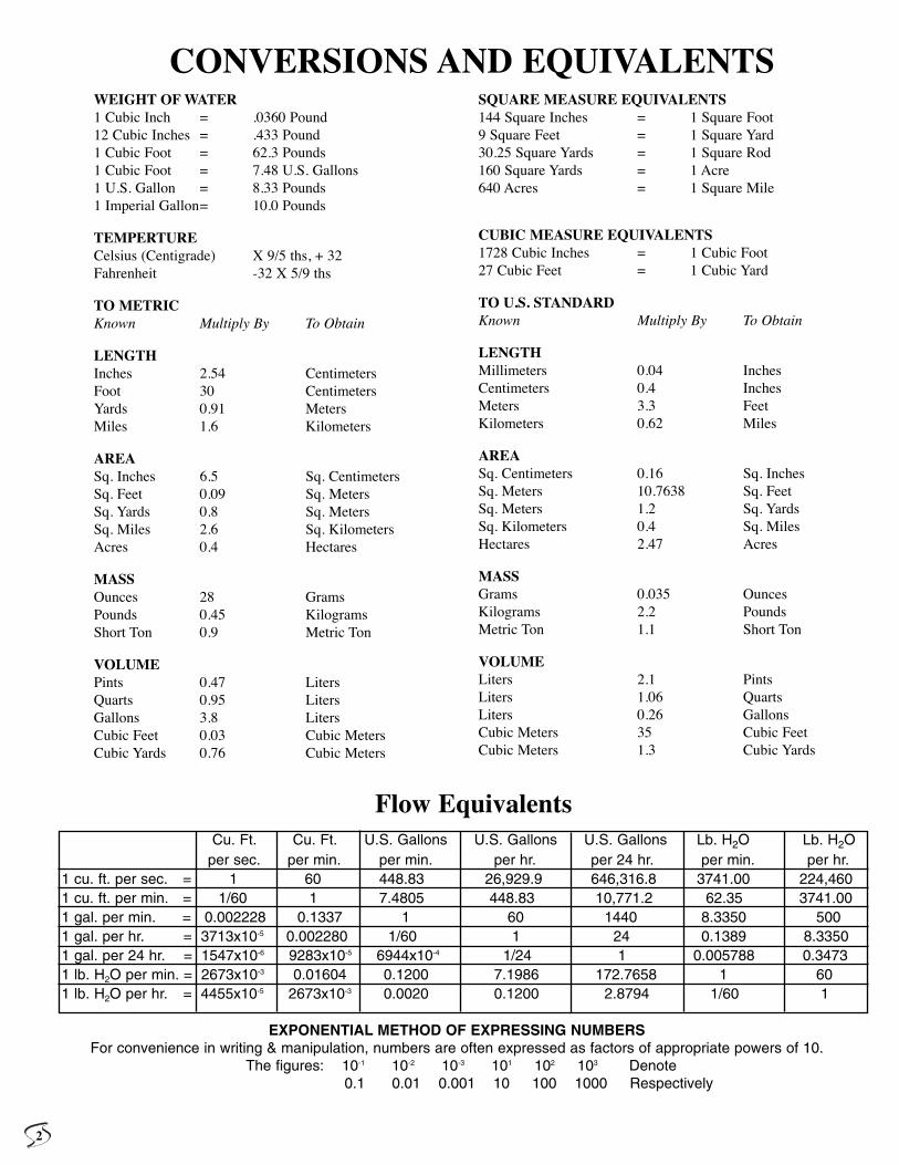
Cu. Ft. Cu. Ft. U.S. Gallons U.S. Gallons U.S. Gallons Lb. H2O Lb. H2Oper sec. per min. per min. per hr. per 24 hr. per min. per hr.
1 cu. ft. per sec. = 1 60 448.83 26,929.9 646,316.8 3741.00 224,4601 cu. ft. per min. = 1/60 1 7.4805 448.83 10,771.2 62.35 3741.001 gal. per min. = 0.002228 0.1337 1 60 1440 8.3350 5001 gal. per hr. = 3713x10-5 0.002280 1/60 1 24 0.1389 8.33501 gal. per 24 hr. = 1547x10-6 9283x10-5 6944x10-4 1/24 1 0.005788 0.34731 lb. H2O per min. = 2673x10-3 0.01604 0.1200 7.1986 172.7658 1 601 lb. H2O per hr. = 4455x10-5 2673x10-3 0.0020 0.1200 2.8794 1/60 1
Flow Equivalents
EXPONENTIAL METHOD OF EXPRESSING NUMBERSFor convenience in writing & manipulation, numbers are often expressed as factors of appropriate powers of 10.
The figures: 10-1 10-2 10-3 101 102 103 Denote0.1 0.01 0.001 10 100 1000 Respectively
SHOCK INTENSITYQuick valve closure is defined as the closure time equal to or less than2L seconds. This will cause maximum pressure rise. This pressure risecan be calculated by using Joukowsky’s formula.
PR = WaV (PSI)
144g
PR - pressure rise above flow pressure in pounds per square inchW- the specific weight of liquid, pounds per cubic feet (62.4 for
water)a -the velocity of pressure wave, feet per second (4,000 to
4,500 feet per second average for water)V -the change of velocity - feet per secondg- acceleration due to gravity - Ft./Sec. 2 (32.2)L - the length of pipe in feet from point of valve closure to point
of relief
Point of relief is a larger mass of water in the system to which thebranch is connected. Point of relief could be a larger diameter main orriser, water tank or hot water boiler.
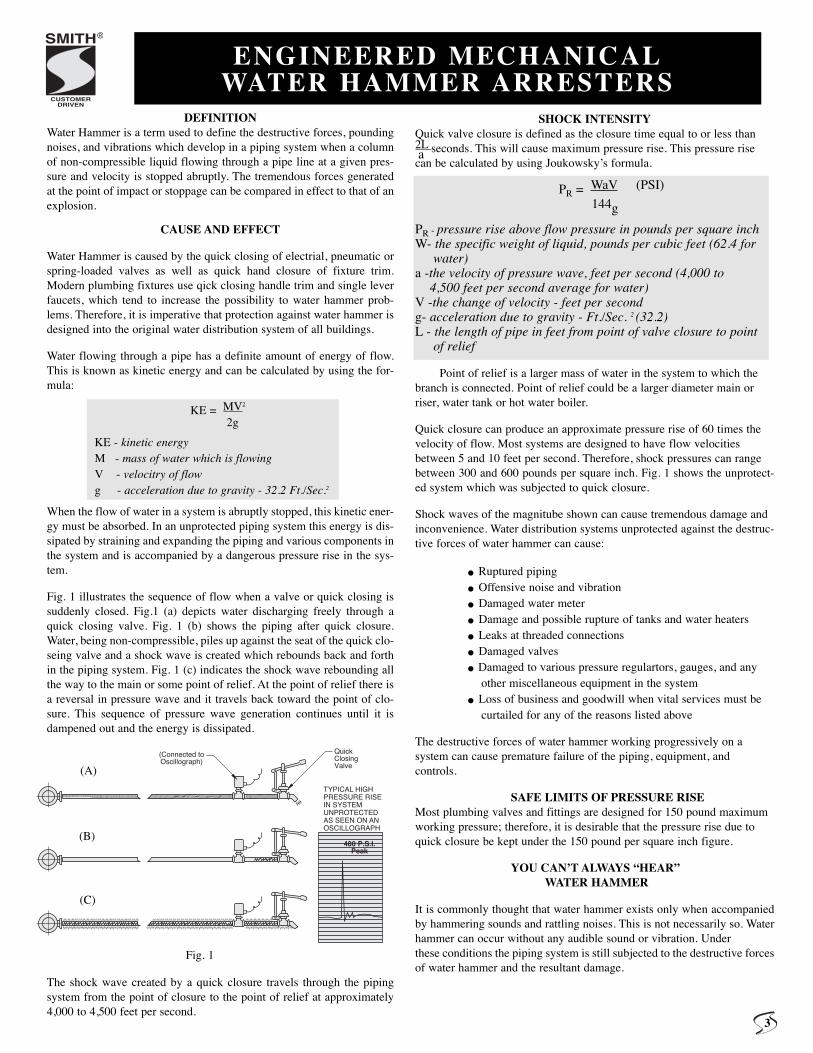
Quick closure can produce an approximate pressure rise of 60 times thevelocity of flow. Most systems are designed to have flow velocitiesbetween 5 and 10 feet per second. Therefore, shock pressures can rangebetween 300 and 600 pounds per square inch. Fig. 1 shows the unprotect-ed system which was subjected to quick closure.
Shock waves of the magnitube shown can cause tremendous damage andinconvenience. Water distribution systems unprotected against the destruc-tive forces of water hammer can cause:
. Ruptured piping. Offensive noise and vibration. Damaged water meter. Damage and possible rupture of tanks and water heaters. Leaks at threaded connections. Damaged valves. Damaged to various pressure regulartors, gauges, and anyother miscellaneous equipment in the system. Loss of business and goodwill when vital services must becurtailed for any of the reasons listed above
The destructive forces of water hammer working progressively on a system can cause premature failure of the piping, equipment, and controls.
SAFE LIMITS OF PRESSURE RISEMost plumbing valves and fittings are designed for 150 pound maximumworking pressure; therefore, it is desirable that the pressure rise due toquick closure be kept under the 150 pound per square inch figure.
YOU CAN’T ALWAYS “HEAR”WATER HAMMER
It is commonly thought that water hammer exists only when accompaniedby hammering sounds and rattling noises. This is not necessarily so. Waterhammer can occur without any audible sound or vibration. Underthese conditions the piping system is still subjected to the destructive forcesof water hammer and the resultant damage.
(Connected toOscillograph)
480 P.S.I.Peak
QuickClosingValve
TYPICAL HIGHPRESSURE RISEIN SYSTEMUNPROTECTEDAS SEEN ON AN OSCILLOGRAPH
DEFINITIONWater Hammer is a term used to define the destructive forces, poundingnoises, and vibrations which develop in a piping system when a columnof non-compressible liquid flowing through a pipe line at a given pres-sure and velocity is stopped abruptly. The tremendous forces generatedat the point of impact or stoppage can be compared in effect to that of anexplosion.
CAUSE AND EFFECT
Water Hammer is caused by the quick closing of electrial, pneumatic orspring-loaded valves as well as quick hand closure of fixture trim.Modern plumbing fixtures use qick closing handle trim and single leverfaucets, which tend to increase the possibility to water hammer prob-lems. Therefore, it is imperative that protection against water hammer isdesigned into the original water distribution system of all buildings.
Water flowing through a pipe has a definite amount of energy of flow.This is known as kinetic energy and can be calculated by using the for-mula:
KE = MV2
2g
KE - kinetic energyM - mass of water which is flowingV - velocitry of flowg - acceleration due to gravity - 32.2 Ft./Sec.2
When the flow of water in a system is abruptly stopped, this kinetic ener-gy must be absorbed. In an unprotected piping system this energy is dis-sipated by straining and expanding the piping and various components inthe system and is accompanied by a dangerous pressure rise in the sys-tem.
Fig. 1 illustrates the sequence of flow when a valve or quick closing issuddenly closed. Fig.1 (a) depicts water discharging freely through aquick closing valve. Fig. 1 (b) shows the piping after quick closure.Water, being non-compressible, piles up against the seat of the quick clo-seing valve and a shock wave is created which rebounds back and forthin the piping system. Fig. 1 (c) indicates the shock wave rebounding allthe way to the main or some point of relief. At the point of relief there isa reversal in pressure wave and it travels back toward the point of clo-sure. This sequence of pressure wave generation continues until it isdampened out and the energy is dissipated.
The shock wave created by a quick closure travels through the pipingsystem from the point of closure to the point of relief at approximately4,000 to 4,500 feet per second.
ENGINEERED MECHANICALWATER HAMMER ARRESTERS
a
CUSTOMERDRIVEN
SMITH®
3
(A)
(B)
(C)
Fig. 1
REQUIRED AIR CHAMBER FAILURENominal FLOW Volume ExceededPipe Dia. Conditions Cu. In. Diameter Hight 150 P.S.I.G. Total1/2 Length Pipe 30 3/4 56.7” 1st Hour 2nd Day3/4 50 Ft. 50 1 58.2” 1st Hour 3rd Day
1 Flow Pressure 75 1 1/4 50” 1st Hour 2nd Day1 1/4 60 P.S.I.G. 110 1 1/2 54” 1st Hour 2nd Day1 1/2 Velocity 170 2 50.5” 1st Hour 1st Day
2 10 Ft./Sec. 300 3 40.5” 1st Hour 2nd Day
CONTROL OF WATER HAMMERThe old conventional method of controlling water hammer has been the “pipe cappedair chamber.” Unforturately, this antiquated method is still used, even though the airchamber cannot control water hammer due to many inherent limitations.
Traditionally, air chambers have been installed using random lengths of pipe, usuallythe same nominal size as the branch to which they are connected. Air chambers arefound to be as short as just several inches to a maximum of 18 inches as specified insome codes.
S. M. Dawson and A. A. Kalinske of the Iowa Institute of HydraulicResearch in their Technical Bulletin #3, titled “WATER SUPPLYPIPING FOR THE PLUMBING SYSTEM” determined after a series of tests, the rec-ommended volume of air chambers for various conditions of pipe size, length of run,flow pressure and velocity. Table 1 indicates some of their recommendations.
AIR CHAMBERS MUST BE CONSTANTLY MAINTAINED-Air chambers vary quickly become water logged and must be constant-
ly maintained if they are to offer even minimal amount of protection.Recharing often can be accomplished only by draining the complete sys-tem. This type of maintenance on a periodic basis is very expensive andin most building is impossible to perform, since the water supply systemcannot be shut down.
The SolutionSMITH HYDROTROL
An Engineered, MechanicalWATER HAMMER ARRESTER
The extreme limitations of the air chamber have been conclusivelyproven and documented by independent testing laboratories anduniversity researchers. Therefore, it must be concluded that the onlymodern means of protection of the water distribution system from thedestructive forces of water hammer is the installation of an “Engineered,Mechanical Water Hammer Arrester.”
The Smith HYDROTROL is a device which offers positive protection.HYDROTROLS are completely described on the following pages.
Extremely large air chambers are necessary to temporarily control water hammershock to acceptable levels. It may be concluded that “ideally sized air chambers” areexcessive in size. Therefore, the usual short air chamber made of random lengthpieces of pipe offers extremely limited protection. It is also interesting to note that insizing the “ideal air chamber” the pipe diameter of the chamber is increased one nom-inal size so that the necessary volume can be attained.
AIR CHAMBERS OFFER ONLY
TEMPORARY PROTECTION
Pipe capped air chambers quickly become water logged (completelyfilled with water) and are rendered ineffective in the system. Conclusive tests per-formed at an independent testing laboratory prove that even “ideally sized air cham-bers” (sized by the Dawson and Kelinske method) will quickly become water loggedand ineffective. Table 1 also shows some typical results of tests run on “ideally sizedair chambers.” All air chambers show in the table failed within the first hour. The unitwas considered as having failed when it allowed the pressure rise in the system to goabove 150 P.S.I.G. The same air chambers were completely water logged within threedays. This is conclusive and documented proof that air chambers very quickly becomewater logged and offer no protection to the system against the destructive forces ofwater hammer.
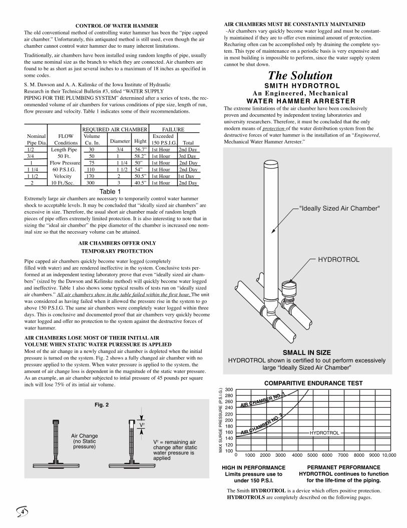
AIR CHAMBERS LOSE MOST OF THEIR INITIAL AIR VOLUME WHEN STATIC WATER PURESSURE IS APPLIED Most of the air change in a newly changed air chamber is depleted when the initialpressure is turned on the system. Fig. 2 shows a fully changed air chamber with nopressure applied to the system. When water pressure is applied to the system, theamount of air change loss is dependent in the magnitude of the static water pressure.As an example, an air chamber subjected to intial pressure of 45 pounds per squareinch will lose 75% of its intial air volume.
Table 1
SMALL IN SIZEHYDROTROL shown is certified to out perform excessively
large “Ideally Sized Air Chamber”
V2
V2 = remaining airchange after staticwater pressure isapplied
Air Change(no Staticpressure)
Fig. 2
COMPARITIVE ENDURANCE TEST300280260240220200180160140120100
0 1000 2000 3000 4000 5000 6000 7000 8000 9000 10,000
HYDROTROL
AIR CHAMBER NO. 1
AIR CHAMBER NO. 2
MA
X S
UR
GE
PR
ES
SU
RE
(P.
S.I.
G.)
HIGH IN PERFORMANCELimits pressure use to
under 150 P.S.I.
PERMANET PERFORMANCEHYDROTROL continues to function
for the life-time of the piping.
4
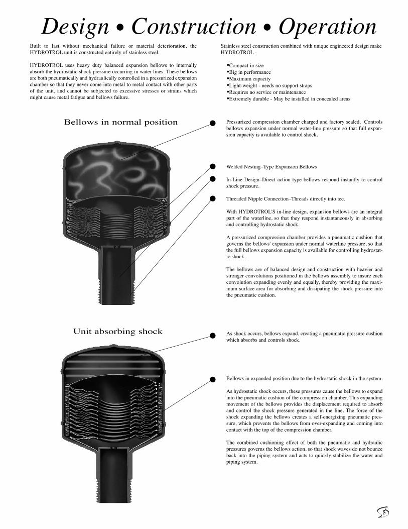
Pressurized compression chamber charged and factory sealed. Controlsbellows expansion under normal water-line pressure so that full expan-sion capacity is available to control shock.
Welded Nesting–Type Expansion Bellows
In-Line Design–Direct action type bellows respond instantly to controlshock pressure.
Threaded Nipple Connection–Threads directly into tee.
With HYDROTROL'S in-line design, expansion bellows are an integralpart of the waterline, so that they respond instantaneously in absorbingand controlling hydrostatic shock.
A pressurized compression chamber provides a pneumatic cushion thatgoverns the bellows' expansion under normal waterline pressure, so thatthe full bellows expansion capacity is available for controlling hydrostat-ic shock.
The bellows are of balanced design and construction with heavier andstronger convolutions positioned in the bellows assembly to insure eachconvolution expanding evenly and equally, thereby providing the maxi-mum surface area for absorbing and dissipating the shock pressure intothe pneumatic cushion.
As shock occurs, bellows expand, creating a pneumatic pressure cushionwhich absorbs and controls shock.
Bellows in expanded position due to the hydrostatic shock in the system.
As hydrostatic shock occurs, these pressures cause the bellows to expandinto the pneumatic cushion of the compression chamber. This expandingmovement of the bellows provides the displacement required to absorband control the shock pressure generated in the line. The force of theshock expanding the bellows creates a self-energizing pneumatic pres-sure, which prevents the bellows from over-expanding and coming intocontact with the top of the compression chamber.
The combined cushioning effect of both the pneumatic and hydraulicpressures governs the bellows action, so that shock waves do not bounceback into the piping system and acts to quickly stabilize the water andpiping system.
Built to last without mechanical failure or material deterioration, theHYDROTROL unit is constructed entirely of stainless steel.
HYDROTROL uses heavy duty balanced expansion bellows to internallyabsorb the hydrostatic shock pressure occurring in water lines. These bellowsare both pneumatically and hydraulically controlled in a pressurized expansionchamber so that they never come into metal to metal contact with other partsof the unit, and cannot be subjected to excessive stresses or strains whichmight cause metal fatigue and bellows failure.
Stainless steel construction combined with unique engineered design makeHYDROTROL -
•Compact in size•Big in performance•Maximum capacity•Light-weight - needs no support straps•Requires no service or maintenance•Extremely durable - May be installed in concealed areas
Design • Construction • Operation
Bellows in normal position •
•••
•
•
Unit absorbing shock
5
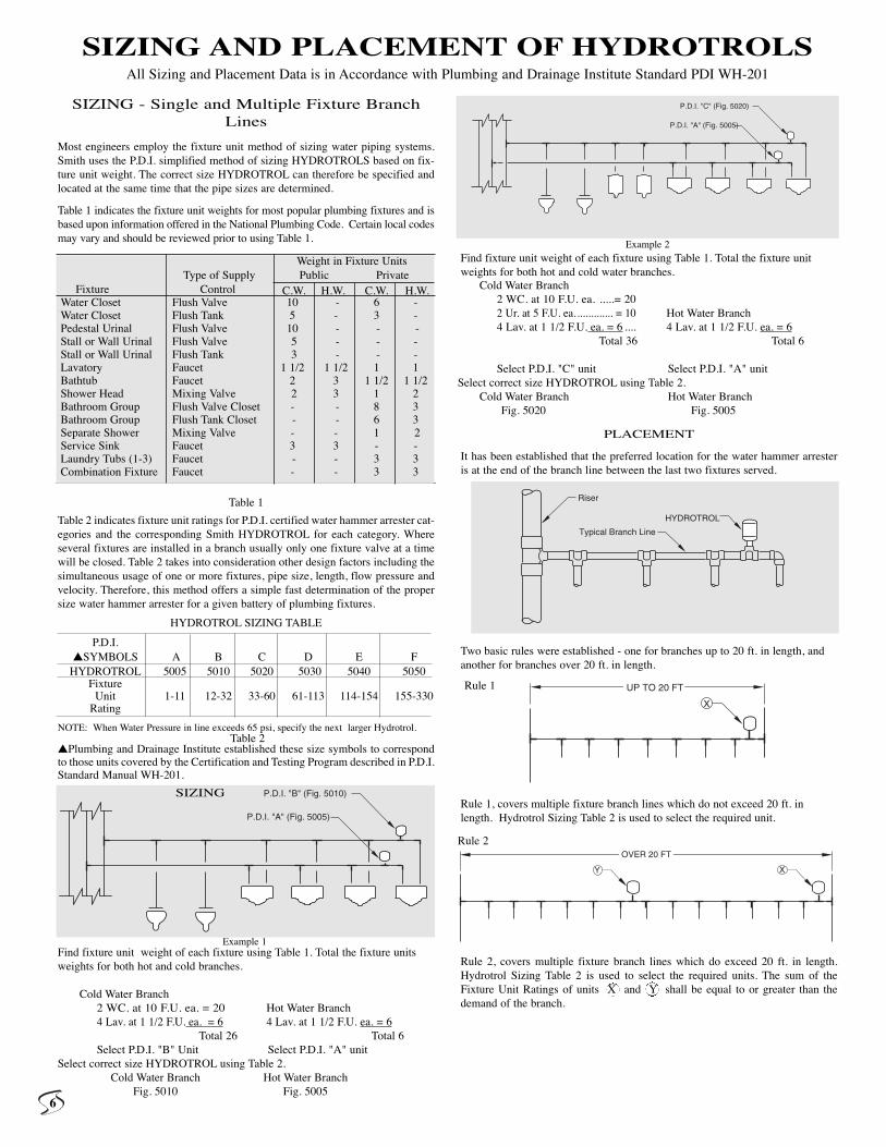
SIZING - Single and Multiple Fixture BranchLines
Most engineers employ the fixture unit method of sizing water piping systems.Smith uses the P.D.I. simplified method of sizing HYDROTROLS based on fix-ture unit weight. The correct size HYDROTROL can therefore be specified andlocated at the same time that the pipe sizes are determined.
Table 1 indicates the fixture unit weights for most popular plumbing fixtures and isbased upon information offered in the National Plumbing Code. Certain local codesmay vary and should be reviewed prior to using Table 1.
Table 1
Table 2 indicates fixture unit ratings for P.D.I. certified water hammer arrester cat-egories and the corresponding Smith HYDROTROL for each category. Whereseveral fixtures are installed in a branch usually only one fixture valve at a timewill be closed. Table 2 takes into consideration other design factors including thesimultaneous usage of one or more fixtures, pipe size, length, flow pressure andvelocity. Therefore, this method offers a simple fast determination of the propersize water hammer arrester for a given battery of plumbing fixtures.
HYDROTROL SIZING TABLE
NOTE: When Water Pressure in line exceeds 65 psi, specify the next larger Hydrotrol.
�Plumbing and Drainage Institute established these size symbols to correspondto those units covered by the Certification and Testing Program described in P.D.I.Standard Manual WH-201.
Find fixture unit weight of each fixture using Table 1. Total the fixture unitsweights for both hot and cold branches.
Cold Water Branch2 WC. at 10 F.U. ea. = 20 Hot Water Branch4 Lav. at 1 1/2 F.U. ea. = 6 4 Lav. at 1 1/2 F.U. ea. = 6
Total 26 Total 6Select P.D.I. "B" Unit Select P.D.I. "A" unit
Select correct size HYDROTROL using Table 2.Cold Water Branch Hot Water Branch
Fig. 5010 Fig. 5005
Find fixture unit weight of each fixture using Table 1. Total the fixture unitweights for both hot and cold water branches.
PLACEMENT
It has been established that the preferred location for the water hammer arresteris at the end of the branch line between the last two fixtures served.
Two basic rules were established - one for branches up to 20 ft. in length, andanother for branches over 20 ft. in length.
Rule 1, covers multiple fixture branch lines which do not exceed 20 ft. inlength. Hydrotrol Sizing Table 2 is used to select the required unit.
Rule 2, covers multiple fixture branch lines which do exceed 20 ft. in length.Hydrotrol Sizing Table 2 is used to select the required units. The sum of theFixture Unit Ratings of units X and Y shall be equal to or greater than thedemand of the branch.
Y X
OVER 20 FT
SIZING AND PLACEMENT OF HYDROTROLSAll Sizing and Placement Data is in Accordance with Plumbing and Drainage Institute Standard PDI WH-201
P.D.I.�SYMBOLS A B C D E F
HYDROTROL 5005 5010 5020 5030 5040 5050Fixture
Unit 1-11 12-32 33-60 61-113 114-154 155-330Rating
P.D.I. "A" (Fig. 5005)
P.D.I. "B" (Fig. 5010)
P.D.I. "A" (Fig. 5005)
P.D.I. "C" (Fig. 5020)
Riser
Typical Branch Line
HYDROTROL
X
UP TO 20 FT
Cold Water Branch2 WC. at 10 F.U. ea. .....= 202 Ur. at 5 F.U. ea.............. = 10 Hot Water Branch4 Lav. at 1 1/2 F.U. ea. = 6 .... 4 Lav. at 1 1/2 F.U. ea. = 6
Total 36 Total 6
Select P.D.I. "C" unit Select P.D.I. "A" unitSelect correct size HYDROTROL using Table 2.
Cold Water Branch Hot Water BranchFig. 5020 Fig. 5005
Rule 1
Rule 2
SIZING
Example 2
Example 1
Table 2
Weight in Fixture UnitsType of Supply Public Private
Fixture Control C.W. H.W. C.W. H.W.Water Closet Flush Valve 10 - 6 -Water Closet Flush Tank 5 - 3 -Pedestal Urinal Flush Valve 10 - - -Stall or Wall Urinal Flush Valve 5 - - -Stall or Wall Urinal Flush Tank 3 - - -Lavatory Faucet 1 1/2 1 1/2 1 1Bathtub Faucet 2 3 1 1/2 1 1/2Shower Head Mixing Valve 2 3 1 2Bathroom Group Flush Valve Closet - - 8 3Bathroom Group Flush Tank Closet - - 6 3Separate Shower Mixing Valve - - 1 2Service Sink Faucet 3 3 - -Laundry Tubs (1-3) Faucet - - 3 3Combination Fixture Faucet - - 3 3
6
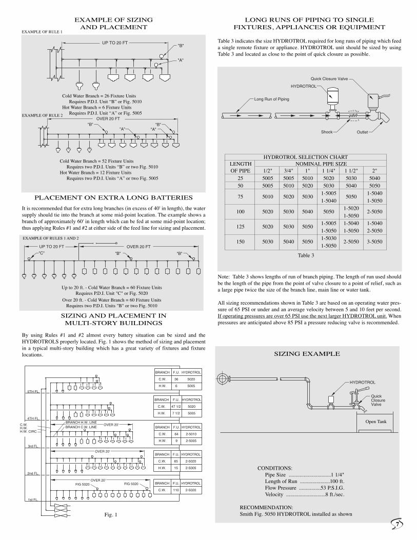
EXAMPLE OF SIZING AND PLACEMENT
PLACEMENT ON EXTRA LONG BATTERIES
It is recommended that for extra long branches (in excess of 40' in length), the watersupply should tie into the branch at some mid-point location. The example shows abranch of approximately 60' in length which can be fed at some mid-point location;thus applying Rules #1 and #2 at either side of the feed line for sizing and placement.
SIZING AND PLACEMENT IN MULTI-STORY BUILDINGS
By using Rules #1 and #2 almost every battery situation can be sized and theHYDROTROLS properly located. Fig. 1 shows the method of sizing and placementin a typical multi-story building which has a great variety of fixtures and fixturelocations.
LONG RUNS OF PIPING TO SINGLE FIXTURES, APPLIANCES OR EQUIPMENT
Table 3 indicates the size HYDROTROL required for long runs of piping which feeda single remote fixture or appliance. HYDROTROL unit should be sized by usingTable 3 and located as close to the point of quick closure as possible.
Note: Table 3 shows lengths of run of branch piping. The length of run used shouldbe the length of the pipe from the point of valve closure to a point of relief, such asa large pipe twice the size of the branch line, main line or water tank.
All sizing recommendations shown in Table 3 are based on an operating water pres-sure of 65 PSI or under and an average velocity between 5 and 10 feet per second.If operating pressures are over 65 PSI use the next larger HYDROTROL unit. Whenpressures are anticipated above 85 PSI a pressure reducing valve is recommended.
Long Run of Piping
HYDROTROL
Quick Closure Valve
Shock Outlet
HYDROTROL
Quick ClosureValve
BRANCH C.W. LINE
BRANCH
C.W.
H.W.
BRANCH
C.W.
H.W.
F.U.
36
6
HYDROTROL
5020
5005
F.U.
47 1/2
7 1/2
HYDROTROL
5020
5005
BRANCH
C.W.
H.W.
F.U.
64
9
HYDROTROL
2-5010
2-5005
BRANCH
C.W.
H.W.
F.U.
65
15
HYDROTROL
2-5020
2-5005
BRANCH
C.W.
F.U.
110
HYDROTROL
2-5020
OVER 20'FIG 5020 FIG 5020
1st FL.
2nd FL.
OVER 20'
3rd FL.
BRANCH H.W. LINEOVER 20'
4TH FL.
5TH FL.
C.W.H.W.H.W. CIRC
"B"
"A"
UP TO 20 FT
"C" "B" "B"
UP TO 20 FT OVER 20 FT
SIZING EXAMPLE
Fig. 1
CONDITIONS:Pipe Size ...............................1 1/4"Length of Run ......................100 ft.Flow Pressure ................53 P.S.I.G.Velocity .............................8 ft./sec.
RECOMMENDATION:Smith Fig. 5050 HYDROTROL installed as shown
HYDROTROL SELECTION CHARTLENGTH NOMINAL PIPE SIZEOF PIPE 1/2" 3/4" 1" 1 1/4" 1 1/2" 2"
25 5005 5005 5010 5020 5030 504050 5005 5010 5020 5030 5040 5050
75 5010 5020 50301-5005
50501-5040
1-5040 1-5050
100 5020 5030 5040 50501-5020
2-50501-5050
125 5020 5030 50501-5005 1-5040 1-50401-5050 1-5050 2-5050
150 5030 5040 5050 1-5030
2-5050 3-50501-5050
Table 3
OVER 20 FT"B"
"A""A""B"
EXAMPLE OF RULE 1
EXAMPLE OF RULE 2
EXAMPLE OF RULES 1 AND 2
Open Tank
Cold Water Branch = 26 Fixture UnitsRequires P.D.I. Unit “B” or Fig. 5010
Hot Water Branch = 6 Fixture UnitsRequires P.D.I. Unit “A” or Fig. 5005
Cold Water Branch = 52 Fixture UnitsRequires two P.D.I. Units “B” or two Fig. 5010
Hot Water Branch = 12 Fixture UnitsRequires two P.D.I. Units “A” or two Fig. 5005
Up to 20 ft. - Cold Water Branch = 60 Fixture UnitsRequires P.D.I. Unit "C" or Fig. 5020
Over 20 ft. - Cold Water Branch = 60 Fixture UnitsRequires two P.D.I. Units "B" or two Fig. 5010
7
STAINLESS STEELBELLOWS TYPE WATER HAMMER ARRESTERS
ALL STAINLESS STEEL
Smith’s bellows arresters are constructed entirely of 304 stainlesssteel for maximum corrosion resistance and decades of reliableoperation. This construction eliminates the possibility of galvaniccorrosion between dissimilar materials within the structure of thearrester.
ALL-WELDED CONSTRUCTION
There are no o-ring seals, crimp joints, or other “weak links” inthe structure. All joints are gas-tungsten arc welded (GTAW) orresistance welded stainless steel to stainless steel. This construc-tion results in a burst pressure greater than 2000 psi, giving a mar-gin of safety over 13 times the maximum operating pressure of atypical 150 psi water system.
TOTALLY METALLIC, WELDED STAINLESS STEEL GASCHARGE CONTAINMENT
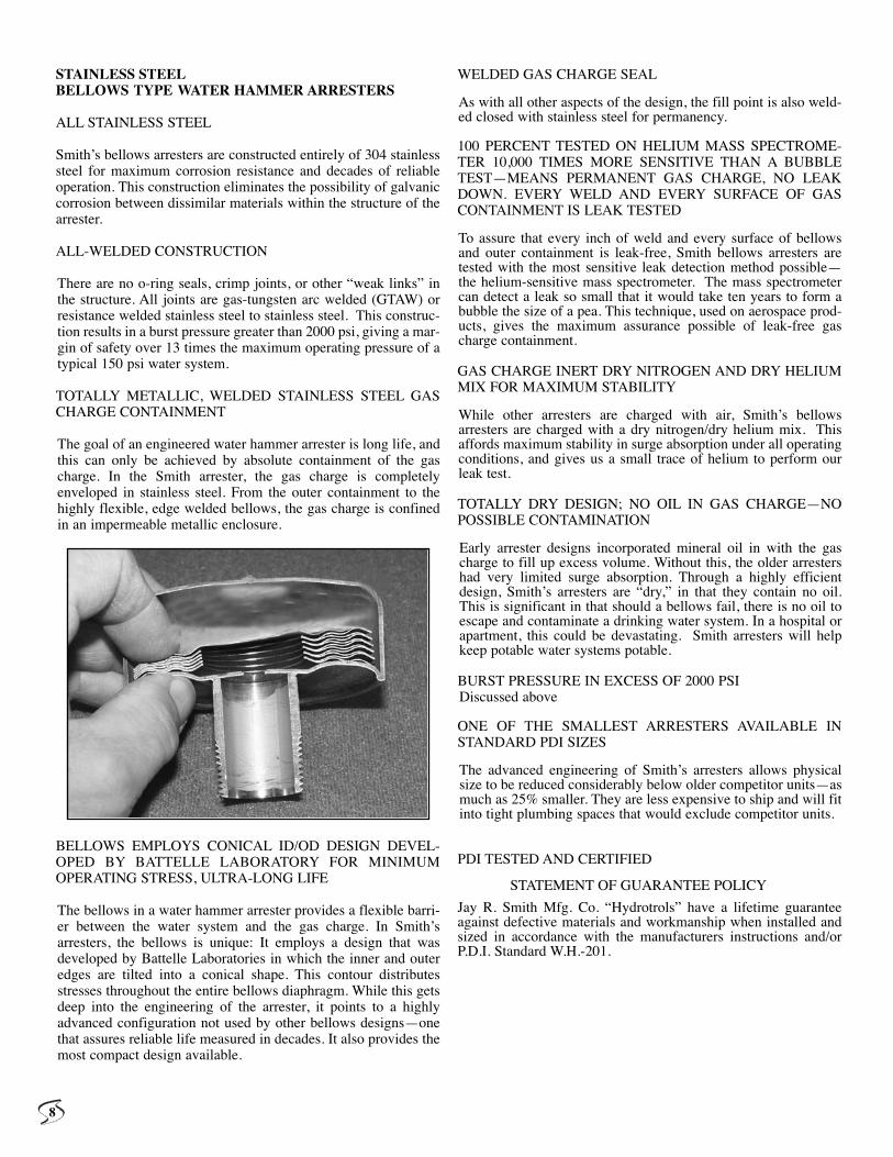
The goal of an engineered water hammer arrester is long life, andthis can only be achieved by absolute containment of the gascharge. In the Smith arrester, the gas charge is completelyenveloped in stainless steel. From the outer containment to thehighly flexible, edge welded bellows, the gas charge is confinedin an impermeable metallic enclosure.
BELLOWS EMPLOYS CONICAL ID/OD DESIGN DEVEL-OPED BY BATTELLE LABORATORY FOR MINIMUMOPERATING STRESS, ULTRA-LONG LIFE
The bellows in a water hammer arrester provides a flexible barri-er between the water system and the gas charge. In Smith’sarresters, the bellows is unique: It employs a design that wasdeveloped by Battelle Laboratories in which the inner and outeredges are tilted into a conical shape. This contour distributesstresses throughout the entire bellows diaphragm. While this getsdeep into the engineering of the arrester, it points to a highlyadvanced configuration not used by other bellows designs—onethat assures reliable life measured in decades. It also provides themost compact design available.
WELDED GAS CHARGE SEAL
As with all other aspects of the design, the fill point is also weld-ed closed with stainless steel for permanency.
100 PERCENT TESTED ON HELIUM MASS SPECTROME-TER 10,000 TIMES MORE SENSITIVE THAN A BUBBLETEST—MEANS PERMANENT GAS CHARGE, NO LEAKDOWN. EVERY WELD AND EVERY SURFACE OF GASCONTAINMENT IS LEAK TESTED
To assure that every inch of weld and every surface of bellowsand outer containment is leak-free, Smith bellows arresters aretested with the most sensitive leak detection method possible—the helium-sensitive mass spectrometer. The mass spectrometercan detect a leak so small that it would take ten years to form abubble the size of a pea. This technique, used on aerospace prod-ucts, gives the maximum assurance possible of leak-free gascharge containment.
GAS CHARGE INERT DRY NITROGEN AND DRY HELIUMMIX FOR MAXIMUM STABILITY
While other arresters are charged with air, Smith’s bellowsarresters are charged with a dry nitrogen/dry helium mix. Thisaffords maximum stability in surge absorption under all operatingconditions, and gives us a small trace of helium to perform ourleak test.
TOTALLY DRY DESIGN; NO OIL IN GAS CHARGE—NOPOSSIBLE CONTAMINATION
Early arrester designs incorporated mineral oil in with the gascharge to fill up excess volume. Without this, the older arrestershad very limited surge absorption. Through a highly efficientdesign, Smith’s arresters are “dry,” in that they contain no oil.This is significant in that should a bellows fail, there is no oil toescape and contaminate a drinking water system. In a hospital orapartment, this could be devastating. Smith arresters will helpkeep potable water systems potable.
BURST PRESSURE IN EXCESS OF 2000 PSIDiscussed above
ONE OF THE SMALLEST ARRESTERS AVAILABLE INSTANDARD PDI SIZES
The advanced engineering of Smith’s arresters allows physicalsize to be reduced considerably below older competitor units—asmuch as 25% smaller. They are less expensive to ship and will fitinto tight plumbing spaces that would exclude competitor units.
PDI TESTED AND CERTIFIED
STATEMENT OF GUARANTEE POLICY
Jay R. Smith Mfg. Co. “Hydrotrols” have a lifetime guaranteeagainst defective materials and workmanship when installed andsized in accordance with the manufacturers instructions and/orP.D.I. Standard W.H.-201.
8
REV. DATE DESCRIPTION BY CKD. BY
WEIGHTPOUNDS
VOLUMECUBIC FEET
FIGURE NUMBER
LOCATION
FIG
UR
EN
UM
BE
R
DIM
EN
SIO
NS
AR
E S
UB
JEC
T T
O M
AN
UF
AC
TU
RE
RS
TO
LER
AN
CE
AN
D C
HA
NG
E W
ITH
OU
T N
OT
ICE
WE
CA
N A
SS
UM
E N
O R
ES
PO
NS
IBIL
ITY
FO
R U
SE
OF
SU
PE
RS
ED
ED
OR
VO
ID D
AT
A
DR
AW
N B
Y:
CH
EC
KE
D B
Y:
AP
PR
OV
ED
BY
:D
AT
E:
SC
ALE
:S
IZE
DR
AW
ING
NU
MB
ER
C
3.25 (83)3.25 (83)3.25 (83)3.25 (83)3.25 (83)3.25 (83)
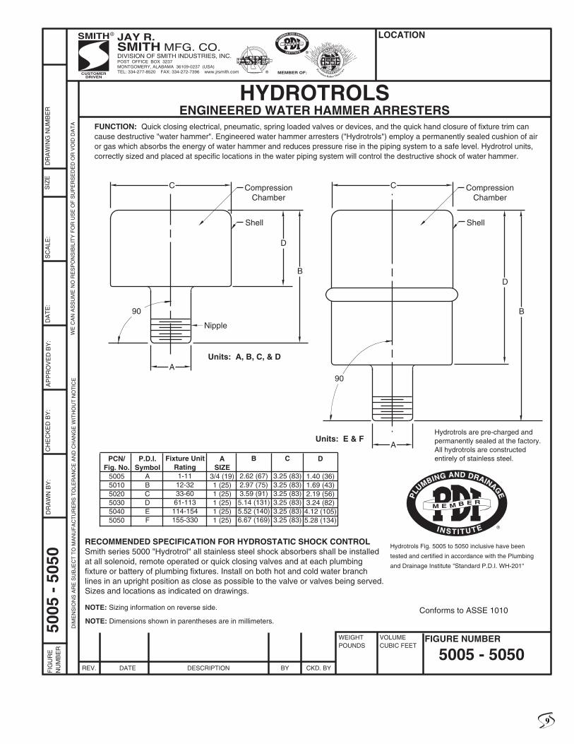
HYDROTROLSENGINEERED WATER HAMMER ARRESTERS
FUNCTION: Quick closing electrical, pneumatic, spring loaded valves or devices, and the quick hand closure of fixture trim cancause destructive "water hammer". Engineered water hammer arresters ("Hydrotrols") employ a permanently sealed cushion of airor gas which absorbs the energy of water hammer and reduces pressure rise in the piping system to a safe level. Hydrotrol units,correctly sized and placed at specific locations in the water piping system will control the destructive shock of water hammer.
RECOMMENDED SPECIFICATION FOR HYDROSTATIC SHOCK CONTROLSmith series 5000 "Hydrotrol" all stainless steel shock absorbers shall be installedat all solenoid, remote operated or quick closing valves and at each plumbingfixture or battery of plumbing fixtures. Install on both hot and cold water branchlines in an upright position as close as possible to the valve or valves being served.Sizes and locations as indicated on drawings.
PCN/Fig. No.
500550105020503050405050
P.D.I.Symbol
ABCDEF
Fixture UnitRating1-1112-3233-6061-113114-154155-330
ASIZE
3/4 (19)1 (25)1 (25)1 (25)1 (25)1 (25)
B
2.62 (67)2.97 (75)3.59 (91)5.14 (131)5.52 (140)6.67 (169)
Hydrotrols Fig. 5005 to 5050 inclusive have been
tested and certified in accordance with the Plumbing
and Drainage Institute "Standard P.D.I. WH-201"
Hydrotrols are pre-charged andpermanently sealed at the factory.All hydrotrols are constructedentirely of stainless steel.
NOTE: Sizing information on reverse side.
5005 - 5050
5005
- 5
050
NOTE: Dimensions shown in parentheses are in millimeters.
D
1.40 (36)1.69 (43)2.19 (56)3.24 (82)4.12 (105)5.28 (134)
Conforms to ASSE 1010
C
B
90
A
CompressionChamber
Shell
Nipple
Units: A, B, C, & D
D
C
B
CompressionChamber
Shell
Units: E & F
D
90
A
JAY R.SMITH MFG. CO.DIVISION OF SMITH INDUSTRIES, INC.POST OFFICE BOX 3237MONTGOMERY, ALABAMA 36109-0237 (USA)TEL: 334-277-8520 FAX: 334-272-7396 www.jrsmith.comCUSTOMER
DRIVEN
SMITH®
MEMBER OF:
®
ASPE®
SANITARY
E
NGINEERINGPrevention Rather Than Cure
9
REV. DATE DESCRIPTION BY CKD. BY
WEIGHTPOUNDS
VOLUMECUBIC FEET
FIGURE NUMBER
LOCATIONF
IGU
RE
NU
MB
ER
DIM
EN
SIO
NS
AR
E S
UB
JEC
T T
O M
AN
UF
AC
TU
RE
RS
TO
LER
AN
CE
AN
D C
HA
NG
E W
ITH
OU
T N
OT
ICE
WE
CA
N A
SS
UM
E N
O R
ES
PO
NS
IBIL
ITY
FO
R U
SE
OF
SU
PE
RS
ED
ED
OR
VO
ID D
AT
A
DR
AW
N B
Y:
CH
EC
KE
D B
Y:
AP
PR
OV
ED
BY
:D
AT
E:
SC
ALE
:S
IZE A
DR
AW
ING
NU
MB
ER
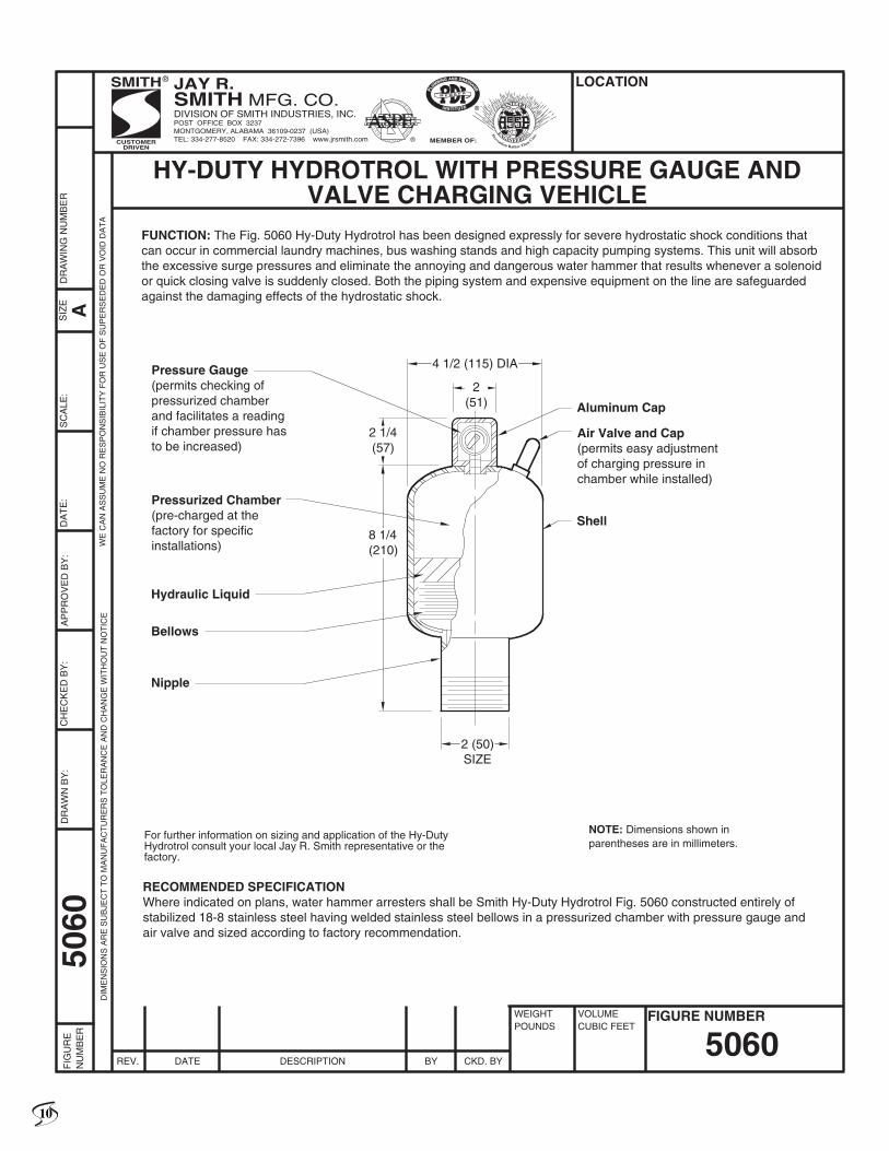
HY-DUTY HYDROTROL WITH PRESSURE GAUGE ANDVALVE CHARGING VEHICLE
FUNCTION: The Fig. 5060 Hy-Duty Hydrotrol has been designed expressly for severe hydrostatic shock conditions thatcan occur in commercial laundry machines, bus washing stands and high capacity pumping systems. This unit will absorbthe excessive surge pressures and eliminate the annoying and dangerous water hammer that results whenever a solenoidor quick closing valve is suddenly closed. Both the piping system and expensive equipment on the line are safeguardedagainst the damaging effects of the hydrostatic shock.
RECOMMENDED SPECIFICATIONWhere indicated on plans, water hammer arresters shall be Smith Hy-Duty Hydrotrol Fig. 5060 constructed entirely ofstabilized 18-8 stainless steel having welded stainless steel bellows in a pressurized chamber with pressure gauge andair valve and sized according to factory recommendation.
4 1/2 (115) DIA
2(51)
2 1/4(57)
8 1/4(210)
2 (50)SIZE
Pressure Gauge(permits checking of pressurized chamber and facilitates a reading if chamber pressure has to be increased)
Pressurized Chamber(pre-charged at the factory for specificinstallations)
Hydraulic Liquid
Bellows
Nipple
Aluminum Cap
Air Valve and Cap(permits easy adjustmentof charging pressure inchamber while installed)
Shell
For further information on sizing and application of the Hy-DutyHydrotrol consult your local Jay R. Smith representative or thefactory.
5060
5060
NOTE: Dimensions shown inparentheses are in millimeters.
JAY R.SMITH MFG. CO.DIVISION OF SMITH INDUSTRIES, INC.POST OFFICE BOX 3237MONTGOMERY, ALABAMA 36109-0237 (USA)TEL: 334-277-8520 FAX: 334-272-7396 www.jrsmith.comCUSTOMER
DRIVEN
SMITH®
MEMBER OF:
®
ASPE®
SANITARY
E
NGINEERINGPrevention Rather Than Cure
10
11
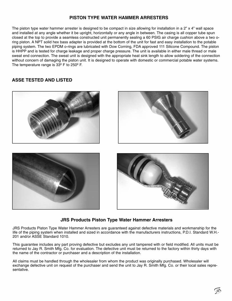
PISTON TYPE WATER HAMMER ARRESTERS
The piston type water hammer arrester is designed to be compact in size allowing for installation in a 2” x 4” wall spaceand installed at any angle whether it be upright, horizontally or any angle in between. The casing is all copper tube spunclosed at the top to provide a seamless constructed unit permanently sealing a 60 PSIG air charge cushion above a two o-ring piston. A NPT solid hex bass adapter is provided at the bottom of the unit for fast and easy installation to the potablepiping system. The two EPDM o-rings are lubricated with Dow Corning, FDA approved 111 Silicone Compound. The pistonis HHPP and is tested for charge leakage and proper charge pressure. The unit is available in either male thread or malesweat end connection. The sweat unit is designed with the appropriate heat sink length to allow soldering of the connectionwithout concern of damaging the piston unit. It is designed to operate with domestic or commercial potable water systems.The temperature range is 33º F to 250º F.
ASSE TESTED AND LISTED
JRS Products Piston Type Water Hammer Arresters
JRS Products Piston Type Water Hammer Arresters are guaranteed against defective materials and workmanship for thelife of the piping system when installed and sized in accordance with the manufacturers instructions, P.D.I. Standard W.H.-201 and/or ASSE Standard 1010.
This guarantee includes any part proving defective but excludes any unit tampered with or field modified. All units must bereturned to Jay R. Smith Mfg. Co. for evaluation. The defective unit must be returned to the factory within thirty days withthe name of the contractor or purchaser and a description of the installation.
All claims must be handled through the wholesaler from whom the product was originally purchased. Wholesaler willexchange defective unit on request of the purchaser and send the unit to Jay R. Smith Mfg. Co. or their local sales repre-sentative.

SERIES 520-T
Water Hammer ArresterPiston Type Water Hammer Arresters, Series 520-T
60 p
sig
char
ge Arrester Chamber, cold rolledand spun closed seamlesschamber
Pipe Size
B
Poly piston. Two EPDMO-rings, pressure-lubricatedwith Dow-Corning 111 SiliconeCompound, FDA approved.
Seamless Spun Reduction
Lead Free Solder JointStandard wrought copperadapter with wrench hex
APressurized air cushion
NPT, male thread
Product Description: Recommended for plumbing fixtures in office buildings, retail, schools, hospitals,correctional facilities, and public buildings. Threaded connection piston type water hammer arrestersconsists of seamless, cold rolled and spun closed copper; pressurized arrester chamber; poly piston withtwo EPDM O-rings.
Features and Benefits:. Designed to absorb and control shock pressure in water lines from surges during quick valve closure. Maximum rated suge pressure: 350 P.S.I.G.. Operating line flow pressure up to 60 P.S.I.G.. Working temperature range: 33˚ to 250˚ F. Listed by the American Society of Sanitary Engineers to ASSE 1010 Standard. Certified and tested by U.S. Testing Co. Inc., Tulsa, OK to ASSE 1010 Standard. IAPMO Listed, File No. 4785
For flow pressures up to 60 P.S.I.G.
Lengthof
Pipe
Nominal Pipe Diameter1/2” 3/4” 1” 1 1/4” 1 1/2” 2”
25’ A A B C D E50’ A B C D E F75’ B C D AE F EF100’ C D E F CF FF125’ C D F AF EF EFF150’ D E F DF FF FFF
Listed:
®
Threaded Connection Piston Water Hammer ArresterSeries 520-T
WATER HAMMER ARRESTER SIZING CHART
NOTE: Dimensional date is subject to manufacturing tolerances and change without notice*NOTE: AA size for residential applications onlyNOTE: Per ASSE Standard, systems exceeding 60 P.S.I.G.shall be installed with a pressure reducing valve upstream of the unit
Smith Pipe Air Dimensions Fixture UnitFig. No. Size, NTP Size Change A B (DIA) Capacity520-T-AA 1/2” AA* 60 psig 5.56” 875” Residential520-T-A 1/2” A 60 psig 6.875” 1.125” 1 to 11520-T-B 3/4” B 60 psig 8.69” 1.38” 12 to 32520-T-C 1” C 60 psig 12.00” 1.38” 33 to 60520-T-D 1-1/4” D 60 psig 12.00” 2.13” 61 to 113520-T-E 1-1/2” E 60 psig 14.56” 2.13” 114 to 154520-T-F 2” F 60 psig 16.38” 2.13” 155 to 330
12

SERIES 520-SC
Water Hammer ArresterPiston Type Water Hammer Arresters, Series 520-SC
Product Description: Recommended for plumbing fixtures in office buildings, retail, schools, hospitals,correctional facilities, and public buildings. Threaded connection piston type water hammer arrestersconsists of seamless, cold rolled and spun closed copper; pressurized arrester chamber; poly piston withtwo EPDM O-rings.
Features and Benefits:. Designed to absorb and control shock pressure in water lines from surges during quick valve closure. Maximum rated suge pressure: 350 P.S.I.G.. Operating line flow pressure up to 60 P.S.I.G.. Working temperature range: 33˚ to 250˚ F. Listed by the American Society of Sanitary Engineers to ASSE 1010 Standard. Certified and tested by U.S. Testing Co. Inc., Tulsa, OK to ASSE 1010 Standard. IAPMO Listed, File No. 4785
Sweat Connection Piston Water Hammer ArresterSeries 520-SC
NOTE: Dimensional date is subject to manufacturing tolerances and change without notice*NOTE: AA size for residential applications onlyNOTE: Per ASSE Standard, systems exceeding 60 P.S.I.G.shall be installed with a pressure reducing valve upstream of the unit
Pipe Size
60 p
si c
harg
e
B
Poly piston. Two EPDMO-rings, pressure-lubricatedwith Dow-Corning 111 SiliconeCompound, FDA approved.
A
Male Sweat Connection
Heat SinkLength
Pressurized air cushion
Arrester Chamber, cold rolledand spun closed seamlesschamber
Listed:
For flow pressures up to 60 P.S.I.G.
Lengthof
Pipe
Nominal Pipe Diameter1/2” 3/4” 1” 1 1/4” 1 1/2” 2”
25’ A A B C D E50’ A B C D E F75’ B C D AE F EF100’ C D E F CF FF125’ C D F AF EF EFF150’ D E F DF FF FFF
WATER HAMMER ARRESTER SIZING CHART
Smith Pipe Air Dimensions Fixture UnitFig. No. Size, NTP Size Change A B (DIA) Capacity520-SC-AA 1/2” AA* 60 psig 5.56” 875” Residential520-SC-A 1/2” A 60 psig 6.875” 1.125” 1 to 11520-SC-B 3/4” B 60 psig 8.69” 1.38” 12 to 32520-SC-C 1” C 60 psig 12.00” 1.38” 33 to 60520-SC-D 1-1/4” D 60 psig 12.00” 2.13” 61 to 113520-SC-E 1-1/2” E 60 psig 14.56” 2.13” 114 to 154520-SC-F 2” F 60 psig 16.38” 2.13” 155 to 330
13
®
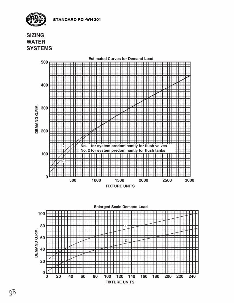
SIZINGWATERSYSTEMS
500
500 1000 1500 2000 2500 3000
400
300
200
100
100
80
60
40
20
00 20 40 60 80 100 120 140 160 180 200 220 240
0
No. 1 for system predominantly for flush valvesNo. 2 for system predominantly for flush tanks
1
1
2
2
FIXTURE UNITS
FIXTURE UNITS
DE
MA
ND
G.P
.M.
DE
MA
ND
G.P
.M.
Estimated Curves for Demand Load
Enlarged Scale Demand Load
14
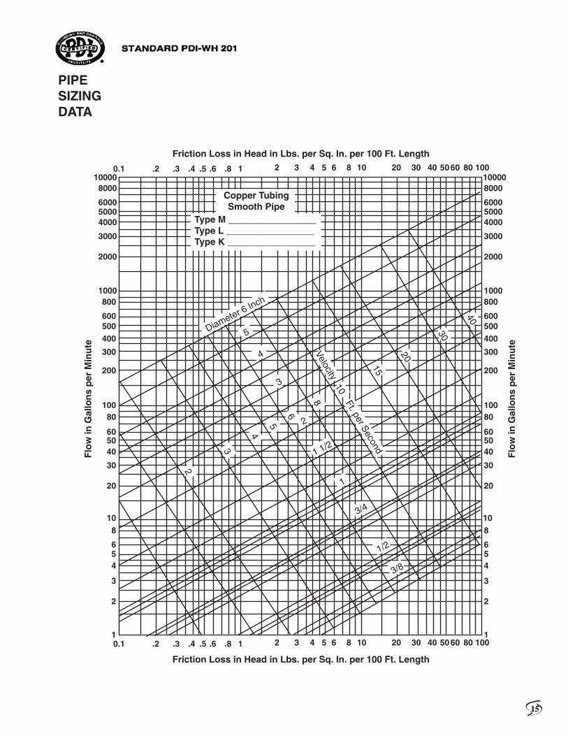
PIPESIZINGDATA
100008000
600050004000
3000
2000
1000800
600500400
300
200
10080
605040
30
20
10
0.1 .2 .3 .4 .5 .6 .8 1 2 3 4 5 6 8 10 20 30 40 50 60 80 100
0.1 .2 .3 .4 .5 .6 .8 1 2 3 4 5 6 8 10 20 30 40 50 60 80 100
8
654
2
3
1
100008000
600050004000
3000
2000
1000800
600500400
300
200
10080
605040
30
20
108
654
2
3
1
Flo
w in
Gal
lon
s p
er M
inu
te
Flo
w in
Gal
lon
s p
er M
inu
te
Friction Loss in Head in Lbs. per Sq. In. per 100 Ft. Length
Friction Loss in Head in Lbs. per Sq. In. per 100 Ft. Length
5
2
3
4
5
8
10
15
20
30
40
6
4
3
2
1
3/4
1/2
3/8
1 1/2
Diameter 6 Inch
Velocity Ft. per SecondCopper TubingSmooth Pipe
Type M _________________Type L _________________Type K _________________
15
100008000
600050004000
3000
2000
1000800
600500400
300
200
10080
605040
30
20
10
0.1 .2 .3 .4 .5 .6 .8 1 2 3 4 5 6 8 10 20 30 40 50 60 80 100
0.1 .2 .3 .4 .5 .6 .8 1 2 3 4 5 6 8 10 20 30 40 50 60 80 100
8
654
2
3
1
100008000
600050004000
3000
2000
1000800
600500400
300
200
10080
605040
30
20
108
654
2
3
1
Flo
w in
Gal
lon
s p
er M
inu
te
Flo
w in
Gal
lon
s p
er M
inu
te
Friction Loss in Head in Lbs. per Sq. In. per 100 Ft. Length
Friction Loss in Head in Lbs. per Sq. In. per 100 Ft. Length
5
6
8
10
2
3
4
5
8
10
15
20
30
40
6
4
3
2
1
3/4
1/2
3/8
1 1/2
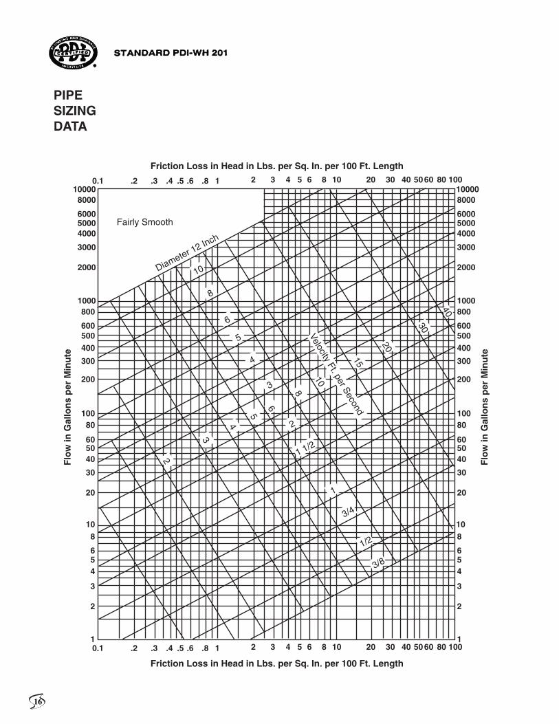
Diameter 12 InchVelocity Ft. per Second
Fairly Smooth
PIPESIZINGDATA
16
100008000
600050004000
3000
2000
1000800
600500400
300
200
10080
605040
30
20
10
0.1 .2 .3 .4 .5 .6 .8 1 2 3 4 5 6 8 10 20 30 40 50 60 80 100
0.1 .2 .3 .4 .5 .6 .8 1 2 3 4 5 6 8 10 20 30 40 50 60 80 100
8
654
2
3
1
100008000
600050004000
3000
2000
1000800
600500400
300
200
10080
605040
30
20
108
654
2
3
1
Flo
w in
Gal
lon
s p
er M
inu
te
Flo
w in
Gal
lon
s p
er M
inu
te
Friction Loss in Head in Lbs. per Sq. In. per 100 Ft. Length
Friction Loss in Head in Lbs. per Sq. In. per 100 Ft. Length
5
6
8
10
2
3
4
5
8
10
15
20
30
6
4
3
2
1
3/4
1/2
3/8
1 1/2
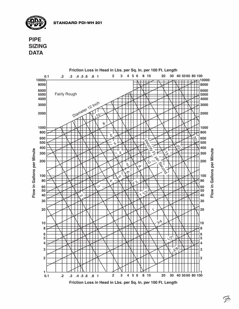
Diameter 12 Inch
Velocity Ft. per Second
Fairly Rough
PIPESIZINGDATA
17
100008000
600050004000
3000
2000
1000800
600500400
300
200
10080
605040
30
20
10
0.1 .2 .3 .4 .5 .6 .8 1 2 3 4 5 6 8 10 20 30 40 50 60 80 100
0.1 .2 .3 .4 .5 .6 .8 1 2 3 4 5 6 8 10 20 30 40 50 60 80 100
8
654
2
3
1
100008000
600050004000
3000
2000
1000800
600500400
300
200
10080
605040
30
20
108
654
2
3
1
Flo
w in
Gal
lon
s p
er M
inu
te
Flo
w in
Gal
lon
s p
er M
inu
te
Friction Loss in Head in Lbs. per Sq. In. per 100 Ft. Length
Friction Loss in Head in Lbs. per Sq. In. per 100 Ft. Length
5
6
8
10
2
3
4
5
8
10
15
20
6
4
3
2
1
3/4
1/2
3/8
1 1/2
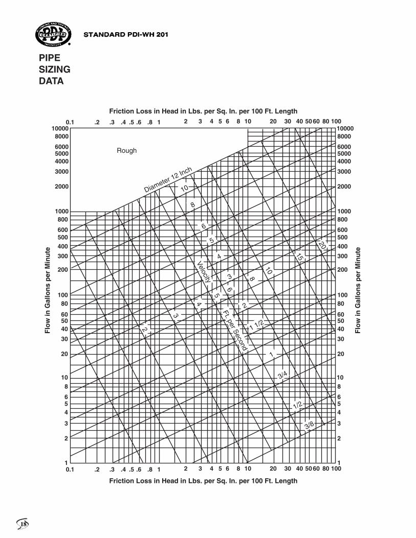
Diameter 12 Inch
Velocity Ft. per Second
Rough
PIPESIZINGDATA
18
110000
8000
60005000
4000
3000
2000
1000
800
600
400
300
200
100
80
6050
40
30
20
10
8
65
4
3
2
1
500
100
80
6050
40
30
20
10
8
6
4
3
2
1
0.8
0.60.5
0.4
0.3
0.2
0.1
.08
.06
.05
.04
.03
.02
.01
5
2 3 4 5 6 8 10 1 2 3 4 5 6 8 10
1 2 3 4 5 6 8 10 1 2 3 4 5 6 8 10
VELOCITY CHART
VELOCITY FT. SECFIG. A
VELOCITY FT. SECFIG. B
VELOCITY CHART
12" P
IPE S
IZE
12" P
IPE
SIZ
E
10"
8"
6" 6"
8"
10"
5"
5"
4"
4"
3 1
/2"
3"
2"
2"
3"
1"
1"
3/4
"
3/4
"
1/2
"
1/2
"
2 1
/2"
2 1
/2"
1 1
/4"
1 1
/4"
3 1
/2"
1 1
/2"
1 1
/2"
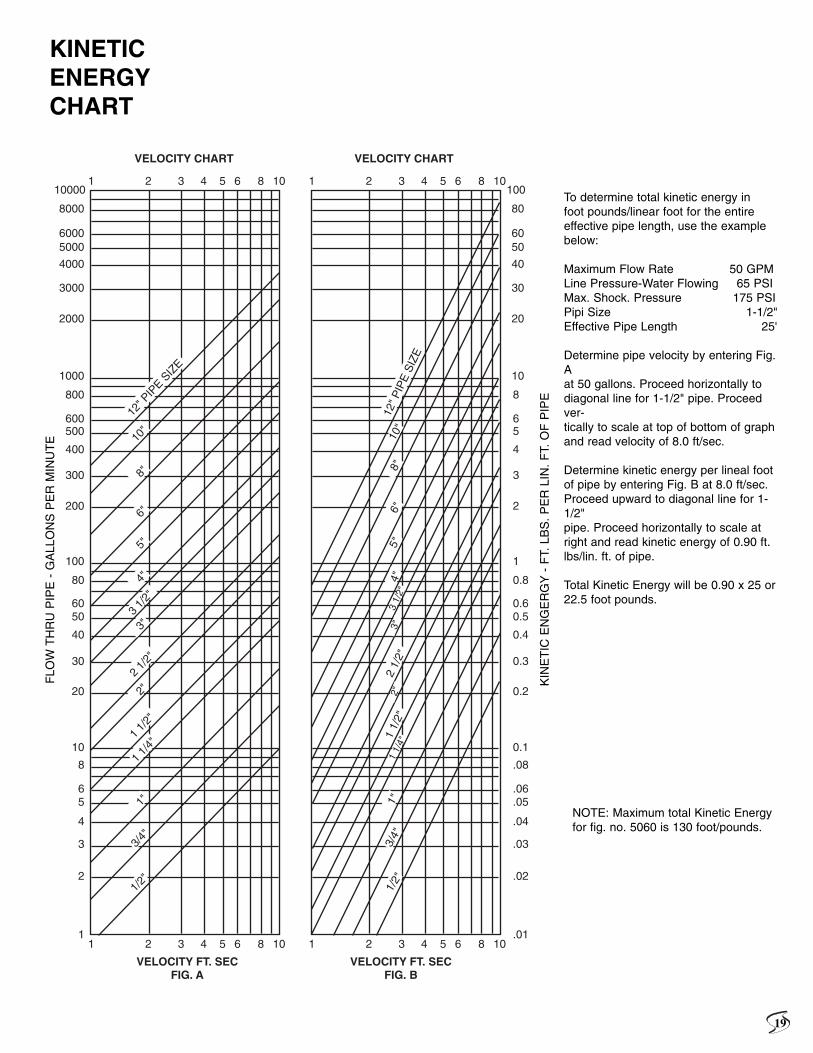
To determine total kinetic energy infoot pounds/linear foot for the entireeffective pipe length, use the examplebelow:
Maximum Flow Rate 50 GPMLine Pressure-Water Flowing 65 PSIMax. Shock. Pressure 175 PSIPipi Size 1-1/2"Effective Pipe Length 25'
Determine pipe velocity by entering Fig.Aat 50 gallons. Proceed horizontally to diagonal line for 1-1/2" pipe. Proceedver-tically to scale at top of bottom of graphand read velocity of 8.0 ft/sec.
Determine kinetic energy per lineal footof pipe by entering Fig. B at 8.0 ft/sec.Proceed upward to diagonal line for 1-1/2"pipe. Proceed horizontally to scale atright and read kinetic energy of 0.90 ft.lbs/lin. ft. of pipe.
Total Kinetic Energy will be 0.90 x 25 or22.5 foot pounds.
NOTE: Maximum total Kinetic Energyfor fig. no. 5060 is 130 foot/pounds.
KINETICENERGYCHART
FLO
W T
HR
U P
IPE
- G
ALL
ON
S P
ER
MIN
UT
E
KIN
ET
IC E
NG
ER
GY
- F
T. L
BS
. P
ER
LIN
. F
T. O
F P
IPE
19
Q. Will water hammer arresters control the movement in pip-ing mains?
A. The movement in piping mains is caused by shock and par-tially by the flow of water through the mains. The greatestmovement is caused by shock which can be controlled by theinstallation of water hammer arresters. The movement causedby water flow can be controlled by the proper placement ofpipe hangers and supports.
Q. Is it possible to control the shock created by pumpingequipment?
A. When a pump shuts off, some degree of shock will be expe-rienced in the discharge line. This is caused by the back surgeof water to the pumping equipment. The shock can be con-trolled in most applications by the installation of a properlysized water hammer arrester. The unit should be installed at atee connection in the vertical discharge line.
Q. Will a water hammer arrester prevent check valve slam?
A. A water hammer arrester will absorb the shock and mini-mize the slam noise. A soft seat in the check valve will thenassure a quiet closure.
Q. Is the shock generated in dishwasher piping controllable?
A. A solenoid or other type of quick closure valve is employedfor dishwasher applications. A properly sized water hammerarrester installed on the pressure side of the solenoid valve willeliminate the shock and noise.
Q. Is the shock generated in home washing machines control-lable?
A. Yes, a properly sized water hammer arrester placed on thecold and hot water supplies to the washing machine willabsorb the shock as caused by quick closure devices.
Q. Will water hammer arresters control the shock experiencedin commercial laundry machines?
A. A violent shock is created in commercial laundry piping asa result of quick closure valves. The 5060 Hydrotrol has beendesigned for severe applications such as this. However, attimes is not large enough to effectively control the situationand another method must be utilized. These applications shallbe submitted with all pertinent data to Smith’s SalesEngineering for evaluation.
Q. Can shock be prevented in other types of liquid conveyingsystems?
A. The 5005-5050 stainless steel bellows units can be usedwith most types of liquid conveyed in a piping distributionsystem. Therefore, if a shock is encountered, it can be con-trolled. When liquids other than water are involved, it is rec-
ommended that Smith’s Sales Engineering group be consultedfor evaluation.
Q. Will water hammer arresters eliminate piping vibration?
A. If the vibration is caused by the occurance of shock in thepiping system it can be avoided if a properly sized water ham-mer arrester is installed near the quick closure valve.
Q. Are water hammer arresters required in the average resi-dence?
A. Yes, a severe shock can occur in the residential piping sys-tem, especially when excessive water pressures are involved.Most of the premature failures of piping, hot water storageheaters, home laundry machines, automatic control valves andflush tanks or valves, may be attributed to shock caused byquick closure valves. Properly sized water hammer arrestersshould be installed on the hot and cold water supply piping tothat fixture, equipment or apparatus wherein shock can be pro-duced. A pressure reducing valve installed on the dischargeside of the water meter can be most helpful in protecting theresidential piping system.
Q. Will water hammer arresters rectify every shock condition?
A. Occasionally, a piping system is improperly designed orinstalled. Therefore, it is necessary to correct the installationbefore you can cure the shock. After this has been accom-plished a properly sized water hammer arrester will rectify theshock condition.
Q. What is the importance of cubic inch displacement in waterhammer arresters?
A. A prescribed amount of cubic inch displacement is requiredfor each type of device intended for the control of shock. Sincethe Hydrotrols are pressurized, its displacement volume is notactually utilized until the water pressure exceeds 60 P.S.I. Bycomparison, the air chamber type device require a displace-ment volume approximately six times that of each Hydrotrolunit.
Q. Are water hammer arresters safe for potable water system?
A. Yes, the bellows & piston type water hammer arresters aresafe for potable water systems. The o-rings used in the pistontype arresters are lubricated with FDA approved Dow-Corning111 Silicone Compound and all solder joints use lead free sol-der.
IMPORTANT: If you have a question that is not answered onthis page or the preceding pages, or if you have a special prob-lem involving hydrostatic shock or water hammer, please con-tact Smith’s Sales Engineering group.
QUESTIONS & ANSWERS
20

JAY R. SMITH JAY R. SMITH MFG. CO. MFG. CO.
PM 10546/06