Embed Size (px)
Citation preview
1
Enhancements to the Linac Coherent Light Source
2
LCLS Strategic Plan
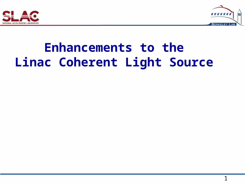
Near term - 2 years “LCLS-I”Increase user capacity flexible beam delivery through optics, linac energy and pulse length changesfixed gap afterburner at second harmonic 16 keV
Intermediate term – 5 years “LCLS-II”Same injector, last 1/3 of linac, same conventional facilities Implement full capacity: simultaneous use of 6 hutchesIncrease spectral capability: present 800eV - 8keV, future 500eV - 24keVImplement polarization controlImplement seeding
Long term – 10 years “LCLS-III”Expansion: additional injectors, linac sections, undulators, conventional facilities higher rep. rate, linac energy, pulse properties, number of stations

3
LCLS upgrade – “LCLS-II”
Increased energy range toward transform limited pulses

4
0.5-15 Å
4-14 GeV
FEE-1Existing 112-m Undulator (1.5-15 Å)
0.75 Åadjustable gap
SHAB30 m
Shortened 74-m Undulator
5 m
FEE-2SXR2 (40 m)
5 mfull polarization control
self-seeding option
6-60 Åadjust. gap
6-60 Åadjust. gap
SXR1 (40 m)4-GeV bypass
new adj. gap und. (0.5-15 Å)
4-GeV SXR and 14-GeV HXR simultaneous op’s with bypass line
2-pulse 2-color
No civil construction. Uses existing beam energy and quality.
full polarization control
ExistingPhase-1Phase-2Phase-3self-seeding HXR option(2 bunches)
EEHG*?
240 nm 6 nm
LCLS-II: 3 Phases over 5 years
* Phys. Rev. Lett. 102, 074801 (2009)
5 m
full polarization control

5
Phase-1 (2nd Harmonic Afterburner)Existing 1.5-15 Å capabilities fully preservedQuick path to 2nd harmonic (0.75 Å) with afterburner (1-2 GW)Full polarization control of 1st or 2nd harmonic
Phase-2 (Soft X-ray Line)Two-pulse, two-color, variable delay (0-50 ps) soft X-rays (6-60 Å)Self-seeding option (6-60 Å) for narrow bandwidth (10-4)Full polarization control in both SASE and self-seeded modesBypass line allows simultaneous 4-GeV & 14-GeV op’s (60 Hz/ea)Possible Echo-Enhanced seeding at 240 6 nm (or shorter?)
Phase-3 (Ultra-Hard X-ray Line)Existing 1.5-Å to 15-Å & 2nd harm. op’s fully preserved0.5 Å (up to 15 Å) by replacing all existing undulators with variable gapFull polarization control at any HXR wavelength
Self-seeding HXR option with two e- bunches (~10 ns spacing)
Summary of three Phases

6
Undulator Parameters
Periods, gaps and peak fields for new LCLS undulators are wellwithin state-of-the-art for hybrid permanent magnet devices
Soft XR
Hard XR
~ 2 x 10¹¹ 1
~ 4 x 10¹¹ 2

7
Timeline compatible with operation
FY10 FY11 FY13FY12 FY14 FY15
Annual 2 month summer downtime
Phase 1 Installation
Phase 2 Installation
Phase 3 Installation
Startup
ED&I
Fabrication

8
Limitations of SLAC Linac
• The SLAC Linac has been in nearly continuous use since May 1966.
• The major components of the Linac are:– Klystrons (240)
• Now 60,000 hr lifetime, replaced as needed, SLAC rebuilds klystrons (50%) and constructs new ones (50%).
– Pulsed modulators (240)• Major upgrades with SLC in 1980s, new upgrades underway
for LCLS: power feeds, modulator controls, safety systems.– RF controls
• Major upgrades with SLC in 1980s, new upgrades underway for LCLS: phase, amplitude, and stability controls and electronics.
– “Three meter” RF copper accelerating structures (960) • No new ones since 1966, none have failed in every day use. • Expected minimum lifetime from now of >20 years without
erosion mitigation. Metallographic tests done on one unit in service for 31 years. Showed only water
cooling line erosion. Vacuum and RF characteristics are fine. Mitigation studies started.

9
Up to 6 more undulator branch lines possible at ±1, ±2, and/or ±4 deg.Existing 3-km SLAC linac can supply 3 different simultaneous 14-GeV, 120-Hz beams or 28-GeV & 14-GeV beams (shared with PEPX).Can also operate in multi-bunch (~10, 10ns apart) mode to feed FEL farm.
Injector Test Facility will be used to develop source technology, do critical beam physics, and also becomes the electron source for LCLS upgrades.
Limitation of present LCLS Facilities
HXRHXRSXRSXR
-4º
-2º
-1º
-0º
+0º
+1º
+2º
+4º
Future FEL Lines
Injector Test Facility
Possible CW, SC-linac, or compact, high rep-rate X-band linac on SLAC site to feed FEL farm.
Longer-Term