Embed Size (px)
Citation preview
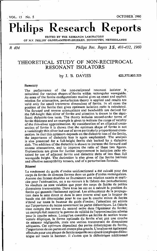
, VOL. 15 No. 5 OCTOBER '1960
Philips Research ReportsEDITED BY THE RESEARCH LABORATORY
OF N.V. PHILIPS' GLOEILAMPENFABRIEKEN. EINDHOVEN. NETHERLANDS
R 404 Philips Res. Repts 15, 401-432, 1960
THEORETICAL STUDY OF NON-RECIPROCALRESONANT ISOLATORS
by J. B. DAVIES 621.372.852.223
SummaryThe performance of the non-reciprocal resonant isolator iscalculated for various shapes of ferrite within rectangular waveguide.As none of the ferrite configurations studied gives an exact and explicitrelation for attenuation, perturbation theory is applied and results arevalid only for small transverse dimensions of ferrite. In all cases theposition of the ferrite that gives optimum isolation ratio is calculated.The forward and reverse attenuations and bandwidth are derived forthe full-height thin sliver of ferrite and attention is drawn to the signi-ficant dielectric-loss term. The theory includes second-order terms offerrite thickness and an example is given to indicate the range ofvalidityof the thin-sliver approximation. By consideration of an elliptical cross-section of ferrite it is shown that the optimum shape of ferrite is nota vanishingly thin sliver but one of some particularly proportioned cross-section. In that this optimum depends on the dielectric loss of the ferrite,the importance of dielectric loss is again emphasized. The analysisis also presented for a full-height ferrite slab backed by a dielectricslab. The addition of the dielectric is shown to increase the forward andreverse attenuations, and to improve the ratio of these two figures.Explanations are given for further improvement in isolation ratio ob-tained by use of adjacent ferrite and dielectric slabs of less than fullwaveguide height. The derivation is also given of the ferrite intrinsicand effective susceptibility tensors, and of a perturbation formula.
RésuméLe rendement du guide d'ondes unidirectionnel a été calculé pour descorps de ferrite de diverses formes dans un guide d'ondes rectangulaire.Aucune des formes étudiées ne fournissant une relation exacte et expli-cite pour l'atténuation, on a eu recours à la théorie des perturbations;les résultats ne sont valables que pour des corps de ferrite de petitesdimensions transversales. Dans tous les cas on a calculé la position duferrite qui garantit I'isolement optimal. Les atténuations de la propaga-tion dans Ie sens direct et dans Ie sens inverse ainsi que la largeur debande ont été déterminées pour le cas que la couche mince de ferrites'étend sur toute la hauteur du guide d'ondes; I'attention est attiréesur l'importance du terme concernant les pertes diélectriques. La théorietient compte des termes du second ordre dans l'épaisseur du ferrite;un exemple fait ressortir la gamme de validité de l'approximation admisepour la couche mince. Lorsqu'on considère un ferrite de section trans-versale élliptique, la forme optimale du ferrite n'est pas une couchede minceur négligeable, mais une section transversale de dimensionsadéquates. eet optimum dépendant des pertes diélectriques du ferrite,I'importance de ces pertes est encore plus grande. L'analyse est égalementeffectuée pour une plaque de ferrite auquelle ona ajouté une plaquediélec-trique sur toute la hauteur. Il s'avère que le diélectrique additionnel

402 J. B. DAVIES
augmente l'atténuation de l'onde directe et de l'onde inverse tout enaméliorant Ie rapport de ces deux grandeurs. On explique I'augmentationobtenue en rapport d'isolement par I'utilisation de ferrites et de blocsdiélectriques adjacents de hauteur inférieure à la hauteur totale du guided'ondes. En outre on indique la détermination des tenseurs intrinsèqueset effectifs de la susceptibilité du ferrite et la formule de perturbation.
Zusammenfassung
Die Leistung des nicht reziproken Resonanz-Isolators wird für ver-schiedene Ferritkörperformen innerhalb eines rechteckigen Hohl-leiters berechnet. Da keine der untersuchten Ferrit-Konfigurationeneine exakte und explizite Relation für die Dämpfung liefert, wirddie Störungstheorie angewandt; die Resultate geiten nur für kleineDurchgangsquerschnitte des Ferrits. In sämtlichen Fällen wird die-jenige Ferrit-Position, die ein optimales Isolationsverhältnis ergibt,berechnet. Die Vorwärts- und Rückwärtsdämpfung sowie die Band-breite werden für die volle Höhe der dünnen Ferritschicht abgeleitet;auf die Bedeutung der dielektrischen Verluste wird hingewiesen. DieTheorie enthält G1ieder zweiter Ordnung in der Ferritdicke, und es wirdein Beispiel angeführt, um den Gültigkeitsbereich der Dünnschicht-Näherung aufzuzeigen. Durch Betrachtung eines elliptischen Ferrit-querschnitts wird gezeigt, daB die optimale Form des Ferrits nicht eineverschwindend dünne Schicht ist, sondern ein in ganz bestimmter Weiseproportionierter Querschnitt. Dadurch, daB dieses Optimum von dendielektrischen Verlusten im Ferrit abhängt, wird die Bedeutung dieserVerluste noch mals unterstrichen. bie Analyse wird ferner für einenFerritblock voller Höhe ausgeführt, der mit einem dielektrischen Blockhinterlegt ist. Es zeigt sich, daB die Einfügung des Dielektrikums dieVorwärts- und Rückwärtsdämpfungswerte erhöht und dadurch das Ver-hältnis dieser beiden Ziffern zueinander verbessert. Es werden Erklä-rungen angeführt für die weitere Verbesserung des Isolationsverhält-nisses durch Verwendung anliegender Ferrit- und Dielektrikblöcke,deren Höhe geringer ist als die volle Höhe des Hohlleiters. Ferner werdendie Ableitung für die intrinsiken und effektiven Suszeptibilitätstensorendes Ferrits sowie eine Störungsformel angegeben.
1. Introduetion
In 1948Tellegen 1) discussed the possibility of a non-reciprocal device whichhe termed a "gyrator", whose operation could rely on the use of a mediumwith a permeability or permittivity in the form of a non-symmetric tensor. Thedevice he was proposing would violate the reciprocity theorem, which propertyit would have in common with such existing devices as the Faraday rotator oflight and a mechanical system including a gyroscopic coupler. Tellegen alsosuggested that ferromagnetic media would be suitable, as having the requiredform of permeability when subjected to a steady magnetic field.
In 1952 Hogan 2) showed that a non-reciprocal microwave attenuator (orisolator) could be contructed utilizing the Faraday-rotation effect that followsfrom the non-symmetric permeability tensor of a ferrite. His experiment wasexactly analogous with Lord Rayleigh's classical experiment on the Faradayrotation of light. During the following year, Kales, Chait and Sakiotis 3)produced a non-reciprocal microwave component in which rectangular wave-guide was partially filled with ferrite subjected to a saturating magnetic field.

NON·RECIPROCAL RESONANT ISOLATORS 403
In this component, as distinct from the Faraday-rotation type of device, thereis an inherent absorption of energy at the resonant frequency, and so it istermed a resonant isolator. Since 1953 much workhas been done on this typeof isolator, most of the work being of a' practical nature owing to the com-plexity of a theoretical approach. .
In the following work, the attenuation in each direction is calculated forvarious configurations of ferrite within rectangular waveguide pr.opagating thedominant TE mode. The attenuation is derived as a function of frequency sothat the isolator bandwidth can be derived. Most attention is given to the iso-lator performance at resonance, where the values of interest are the reverse(higher) loss per inch of ferrite and the ratio of forward to reverse loss (orisolation ratio). Both these values are of great practical importance, though, asa low reverse loss per inch can generally be compensated by Iengthening thedevice, the figure of merit of more fundamental interest is the isolation ratio.Van Trier 4), Lax 5) and others have derived this ratio, assuming electric losses,to be negligible, although a few people, including Lax 6), have suggested thatelectric losses could degrade the ratio. In the following theory it is shown thatelectric losses are almost always important, in particular in the problem ofoptimizing the proportions of the ferrite to be used in the isolator.The theory of the full-height ferrite slab is extended to include second-order
effects and indicates the range of validity of the first-order, or "thin-slab",approximation. Unfortunately the results are complex and make impossiblea very concise conclusion to the problem.The theory is given of a ferrite rod of smaIl elliptical cross-section, which
brings out a number of important features. It shows that the optimum ferriteshape is not a vanishingly thin sliver, as is often supposed, but one of someparticularly proportioned cross-section. A formula is given from which theoptimum proportions can be derived.Experimental investigations have been made (by Beljers 7), Weiss 8) and
others) of the effect of dielectric loading of the ferrite in a resonant isolator.No theoretical account appears to have been given of such dielectric loading.This paper therefore includes the first-order (or "thin-silver") solution of theresonant isolator utilizing a full-height ferrite slab backed by a slab of dielec-tric material.
Sections 2, 3 and 4 are tutorial In nature and include calculations whosèresults are used continuaIly in the succeeding three sections.A few equations may be pointed out for their applicability to the long ferrite
samples employed in resonant isolators. Equation (100) gives the very simplerelation between demagnetizing factors and ferrite proportions. The appliedmagnetic field, and the internal magnetic field are given in terms of ferriteproportions by eqs (102) and (106). This latter relation can be used to verifythat the ferrite is in fact saturated at a particular resonant frequency.

dM ay- = y MAH+ - {MA(MAH)} .dt . IMI
(3)
404 J. B. DAVIES
2. The magnetic susceptibility tensor
The equation of motion of a lossless ferrite has the following form:dM- = y MAH, (1)dt . .
where ;EI is the magnetic field, M is the intensity of magnetization, and y is thegyromagnetic ratio (a negative constant for the ferrite).
This equation implies that the magnetization vector would precess indefi-nitely around a static applied field, whereas in practice damping factors tendto align the magnetization with the field. The decay of the angle of precessionis taken to be exponential with time, and so has an associated time constantcalled the "relaxation time". This phenomenological form of damping givesthe following equation of motion, as introduced by Bloch 11) and applied toferromagnetic resonance by Bloembergen 12):
dM M-Mo IMI H-=yMAH----+--, (2)ili T . Iffl T
where T is the relaxation time and Mois the equilibrium magnetization in thepresence of H.
An alternative form of damping was introduced by Landau and Lifshitz 13)
as:
Earlier work of Bloembergen's omitted certain terms from eq. (2) but in itsmost recent form it gives the same result for the susceptibility tensor as theL-L type damping if the microwave magnetization and magnetic fields aresmall compared with the static magnetization and field, and if a TlyllHI= 1.It appears that a and T are approximately independent of frequency, whilst theirdependence on magnetic field has yet to be established.Thé derivation of the susceptibility tensor is now given for a rectangular
coordinate system, taking eq. (3) as the equation of motion.
(5)
Let H= (hz, hy, Hz + hz), M= (mz, my, M« + mz) , (4)
where static values are denoted by upper-case letters. Let the microwave fieldshave time dependence eiw1•
Substituting in eq. (3) we have from the z component:
Assuming small microwave signal we have 'mz, my «Mz and he, hy « H~'and so from eq. (5):

NON-RECIPROCAL RESONANT ISOLATORS 405
Now ignoring mz and hz we have from eq_(3):iw- ma;= my Hz - hy Mz - a {ha;Mz - ma;Hz} ,y
(6)
iw- my = ha;M; - ma; Hz - a {hyMz - myHz}. (7)y
As eqs (6) and (7) give the linear relations between ha;, hy and me, my, they can becombined to form an explicit tensor relation between the column vectors
(ma;) and (ha;):my hy
(ma;) = (~-iK)(ha;),,my IK X hy
(8)
where
~
iwa )Mz (1 + a2) - - ~-n,~
(9)X=------------~------~-
~2 iwa w2 ~
Hz (1 + a2) ------ (yHz y2Hz2 )
andiw
Mz---yHz'
i« = ---------------------.,---Hz ~(l + a2) _ 2iwa _~ ~
( -u, y2Hz2 SThe tensor formulation of eq. (8) was first put forward by Polder 14). Equa-
tions (9) and (10) give the resonant frequency of an unbounded medium offerrite to be w = lylHz.
X and K are both real when, and only when, a is zero, and so corresponds toa ferrite with infinite relaxation time. Such a ferrite would therefore have aHermitian susceptibility tensor and this Tellegen has shown to be a necessarycondition for media to 'be non-dissipative.3. The effective magnetic susceptibility tensor3.1. The Kittel resonant frequency
(10)
It has been shown in sec. 2 that an unbounded medium of magneticallysaturated ferrite exhibits a resonance at frequency w = lylHz. That is the fre-quency at which there is a peak in magnetization for a given value of micro-wave field.For a bounded volume of ferrite there are discontinuities in the magnetic
field at the ferrite surface. If the effect is being studied of a ferrite sample in amicrowave field, there arises a more pertinent resonant frequency, - that atwhich there is a peak in magnetization within the ferrite for a given value ofmicrowave field just outside the ferrite. This resonant frequency was first deriv-ed by Kittel 15). The ferromagnetic resonance in unbounded media is asso-

3.2. The effective magnetic susceptibility tensor
From eqs (4) and (8) of the previous section we have:
M ~ ( ~ -~" Dw',~ (X",) H"',
where Hint is the internal magnetic field vectorand
(11)
406 J. B. DAVIES
ciated with a singularity (or for the non-ideal ferrite, a peak in magnitude) ofthe susceptibility-tensor components. Similarly we have that the resonance of abounded volume of ferrite is associated with a singularity (or peak in magni-tude) of the "effective susceptibility tensor". This tensor relates the magneti-zation to the magnetic field immediately outside the ferrite (or "external"field). The tensor is only applied to ferrite samples of small dimensions com-pared with the effective microwave wavelength. The external field is thereforeuniquely defined.
(12)
Now consider a ferrite sample for which de!pagnetizing factors can be de-fined, i.e. in the form of an ellipsoid with principal axes oriented along the x,y, z coordinate axes and with axes that are much smaller than both the eddycurrent skin depth and wavelength in each corresponding direction.
The equations for the demagnetizing effect on magnetic fields are:
or, in matrix form:
Hzint = Hzext_ NzMz lHyint = Hyext_ NyMy
Hzint = Hzext _ NzM;;
(13)
Hint = Hext _ (N) M,
where Hext is the external magnetic field vectorand
(14)
(
Nz
(N) = ~oNy
o(15)
From eqs (11) and (14) we have
- . (1 + NzxH~xt = «1) + (N) (Xint)) HInt = Nyi~ ~ ) Hint.
1+ NzXo
(16)1 +Nyxo

NON-RECIPROCAL RESONANT ISOLATORS
Forming the reciprocal matrix gives:
(
1 + NyX Nr;iK
Hint = ~ -N;iK 1 +ONzx o )o Hext,
FI(l + NzXo)and hence:
. 1M=-
F (
X + NY(X2 - K2) =i« 0)i« X + Nz(X2 - K2) 0 n=.o 0 Fxo/(l + NzXo)
F = {I + X(Nz + Ny) + NzNy (X2 - K_2)}.where
Putting eq. (18) in the form
M = (Xerr)Hext
defines the effective susceptibility tensor.X, K and Xo as used in eqs (18) and (19) are given by eqs (9), (10) and (12)
in terms of Hzlnt. Now denoting by H and M the external (or applied) staticmagneti,c field and the static magnetization, we derive from eq. (13) that
Hz=H-NzM.
Substitution in eqs (9), (10) and (12) gives
X _ r M {r(l + a2) (H- NzM)- iwa}F - {B C (1+ a2) - w2 + iwa (B + C)} ,
t« rM i wF = {B C (1 + a2) - w2+ iwa (B + C)} ,
X2 - K2 r2 M2 (1 + a2)F {B C (1+ a2) - w2+ iwa (B + C)}
whereB = Irl {H + (Nz- Nz) M},
C = Irl {H + (Ny - Nz) M}.
Substituting the above into eq. (18) gives the susceptibility tensor:
IrlM(Xeff) = {B C (1 + a2) - w2+ iwa (B + C)} X
CCl + a2)+ iwa +iw 0
(-iw B(l + a2) + iwa 0 ) (27)
X 0 0 {BCCl+a2)-w2+iwa(B+C)}'
IrlH
407
(17)
(18)
(19)
(20)
(21)
(22)
(23)
(24)
(25)
(26)

408 .B. DAVIES
In manyapplications the lossy terms (or else the "phase" terms) of the effec-. tive susceptibility tensor are required, i.e. the skew-Hermitian (or else theHermitian) component of the tensor. For use in such applications (as in secs5, 6 and 7) the real and imaginary parts of the tensor elements are now given.
If
. c= Xxv 0) C'><+iXU ••X'XV+ iX"xv
M/~)(Xerr) = x~x Xvv o = X'vx + iX"Vx X'vv + tx" vu (28)'0 Xzz 0 0
X'XX = K{C(BC- w2) + a2B(2C2 + w2)},
x"xx = -K a w {C2(I + a2) + w2},
x'vv = K{B(BC- w2) + a2C(2B2 + w2)},
X"vv = -K a w {B2(I + a2) + w2},
X'VX = - X'XV= - Ka w 2(B + C),
x"vx = -x"xv = -K w {(BC-w2)+a2B Cl,
(29)
and x' xx, x" xx, ... , are all real, then:
where
K= IrlM{(BC [1 + a2]- w2)2+ a2w2(B + C)2} ,
and B, C are given by eqs (25), (26).This gives the resonance frequency to be
(30)
Ik
o(32)
.,- ./-:-------,-.,.-,---,------:----:-w= liBC = Irll'{H+(Nx-Nz)M}{H+(Nv-Nz)M}. (31)
At this frequency there is a sharp maximum in the magnitude ofthe lossy terms(x" xx, x" uu»x' xv and x'vx). The remaining terms go through zero just abovethis frequency.
For reference, the relation is given here between the "Polder" tensor com-ponents and the effective susceptibility tensor. The Polder tensor is the intrin-sic permeability tensor, giving:
Bint = (:. 0
-iK
and so comparison with eq. (11) identifies the terms Ik and !Ls.The relation is given for the particular case (such as arises in secs 5 and 7)
of a thin sliver of ferrite whose plane contains the direction of propagation ofelectro-magnetic waves and the direction of the static magnetic field. The threedemagnetizing factors are Nx = 1, Nv = N; = 0 and we have:
NON-RECIPROCAL RESONANT ISOLATORS 409------------------------------
/
1- = (1- Xxx),ft
ft2 - K2-- = (1+ Xvv),
ft
(33)
(34)
i«- = Xvx;ft
ft and K can be separately derived from say eqs (33) and (35) but the forms ofl/ft, (ft2 - K2)/ft and iK/ft are the most commonly occurring in the problemssolved.
(35)
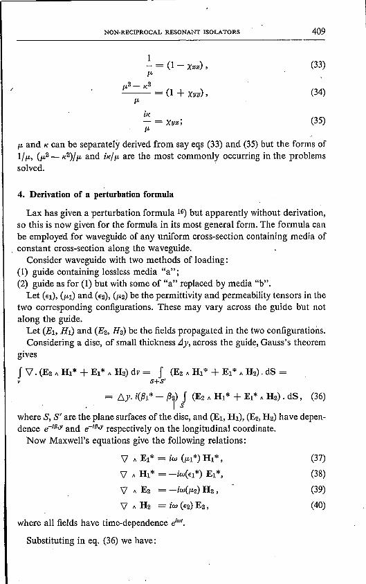
4. Derivation of a perturbation formula
Lax has given a perturbation formula 16) but apparently without derivation,so this is now given for the formula in its most general form. The formula canbe employed for waveguide of any uniform cross-section containing media of
, constant cross-section along the waveguide.Consider waveguide with two methods of loading:
(1) guide containing lossless media "a";(2) guide as for (1) but with some of "a" replaced by media "b".
Let (El), (ftl) and (E2), (ft2) be the permittivity and permeability tensors in thetwo corresponding configurations. These may vary across the guide hut notalong the guide.
Let (El, Hl) and (E2, H2) be the fields propagated in the two configurations,Considering a disc, of small thickness Lly, across the guide, Gauss's theorem
gives
J \1. (E2 A Hl* + El* A H2) dv = I (E2 A Hl* + El* A H2). dS =v ~r
= 6y· i({3l* - (3i) ) (E2 A Hl* + El* A H2). dS, (36)
where S, S' are the plane surfaces of the disc, and (El, HI), (E2, H2) have depen-dence e-1fJ,Y and e-1fJ,y respectively on the longitudinal coordinate.
Now MaxweII's equations give the following relations:
\l A Ei" = iw (ftl*) Hl*,
\l A Hl* = -iW(El*) Ei",
\l A E2 = -iW(ft2) H2,
\l A H2 = iw (E2)E2 ,
where all fields have time-dependence dW1•
Substituting in eq. (36) we have:
(37)
(38)
(39)
(40)
410 J. B. DAVIES
i(f3I* - f32) J (E2" HI* + E~*" H2). dS =s
w J {HI*' (,6P.)H2 + EI*. (,6€) E2}dSf32 - f31= ~<I=S,---;;,..--:- .__ -:- __
J {E2" HI* + EI* "H2}' dSS
(45)
1= - J {(V'"E2).HI*-(V' "HI*).E2 + (V' "EI*).H2-(V' "H2).EI*} dv
6Y v
= iw J {E2.(€I*)EI*-HI*'(P.2)H2+H2'(P.I*)HI*-EI*.(€2)E2}dv. (41)6Y v
Now configuration 1 is non-dissipative, and so the tensors (€1)and (P.l) areHermitian. It can readily be shown that
E2. (€I*)EI* = EI* . (€1)E2 (42)and H2. (p.I*)HI* = HI*. (p.I)H2. (43)
Noting also that f31*= f31,we have by substitution:
(f32 - f31) J (E2" HI* + EI* " H2). dS =S
w= - J {HI*. (P.2 - P.1)H2 + EI* .(€2 - €1)E2}dv
,6y v
= w J {HI*' (P.2 - P.1)H2 + EI*. (€2- €1)E2}dS. (44)S
From this is formed the final relation:
where 6S is the cross-section of media "b", and (,6p.), (6€) are the differencesin tensors between the two configurations.Equation (45) is exact and so if the fields (El, HI) and (E2,H2) were known,
f32 - f31could be evaluated exactly. However an approximate solution forsmall perturbations can be obtained (assuming the unperturbed fields (El, HI)to be known) by taking (E2,H2)equal to (El, HI) outside media "b", and thencederiving (E2, H2) in media "b".When the formula is used for the resonant isolator, configuration 1 is taken
as empty ·çectangular waveguide supporting the dominant TE mode and con-figuration 2 is the waveguide containing ferrite of small uniform cross-section.If demagnetizing factors for the ferrite can be defined, eq. (45) can be simplifiedto
w J {HI*. (Xefr) Hl + EI*. eg) El} dSf32 - f31= __::<I:.=.s-=-~ _
J {El" HI* + EI* "Hl} . dSS
(46)
where (Xeff) is the effective magnetic susceptibility defined by eq. (20),and (g) is the effective electric s,usceptibility tensor given by
NON-RECIPROCAL RESONANT ISOLATORS 411
10-11 +Nx(€-; 1) ,
0 0
(g)='10- 1
0 0 (47)1+Ny(€-I)
0 0(101- 1)
l+Nz(€-I)10is the permittivity of the ferrite.
5. The full-height slab of ferrite in rectangular waveguide
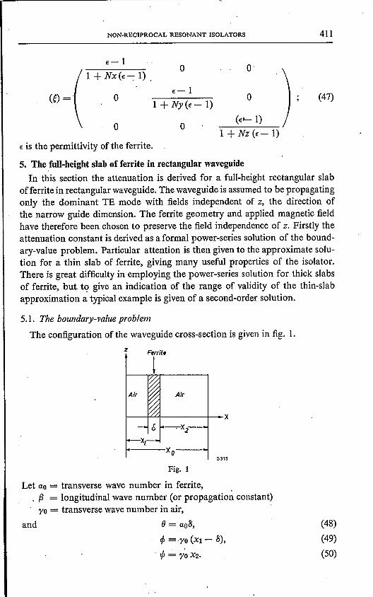
In this section the attenuation is derived for a full-height rectangular slabofferrite in rectangular waveguide. The waveguide is assumed to be propagatingonly the dominant TE mode with fields independent of z, the direction ofthe narrow guide dimension. The ferrite geometry and applied magnetic fieldhave therefore been chosen to preserve the field independenee of z. Firstly theattenuation constant is derived as a formal power-series solution of the bound-ary-value problem. Particular attention is then given to the approximate solu-tion for a thin slab of ferrite, giving many useful properties of the isolator.There is great difficulty in employing the power-series solution for thick slabsof ferrite, but to give an indication of the range of validity of the thin-slabapproximation a typical example is given of a second-order solution.
5.1. The boundary-value problemThe configuration of the waveguide cross-section is given in fig. 1.
Fig. 1
Let ao = transverse wave number in ferrite, ,. {3 = longitudinal wave number (or propagation constant)yo = transverse wave number in air,
and 8 = ao8,cp = yo (Xl - 8),
!fr = y~X2.
(48)
(49)
(50)
412 J. B. DAVIES
Then (51)
~ ~+~=~~ ~where p. and K are the Polder tensor components (defined in eq. (32)) and € isthe relative permittivity of the ferrite.
Solving the boundary-value problem gives the following secular equation(as can be obtained from eq. (Ill) of sec. 7 by putting 7J = 0):
1+ v2f(,8, S)= tan e { , tan é tan!fr+ v(tan!fr-tanq,)- n-{tanq,+tan!fr} = 0,
(53) ,
where v=--,p.ao
(54)
and (55)
~ is required as an explicit function of S, and ,8can be formally developed as apower series in S:
,8(S) = ,8(0) + S,8'(0) + S2 ,8';0) + . .. . (56)
. The required derivatives of,8 can be derived from eq. (53) by means of therelations
(57)
(58)
No terms will be evaluated beyond the second power in S. Noting thattan q, + tan !fr = °when S = 0, successive differentiation of eq. (53) gives thefollowing expressions: .
'öf ~[ 1+ v2 ro] ro~- =-ao -- tan2q, + 2vtan q, + ,-- ,
M 'ao ao(59)
cf xo,8 .- = - sec2 q"'ö,8 ro
vr ~[ 1+ v2 ro] l'?JS2= 2 ao ro sec2 q, ? , - 'ao tan q, + vS'
'ö2f .Xo secê q,-,82 = 3 {,82+ ro2 + 2 ,82ro(X2 - xi) tan q,},ö ro
(60)
(61) .
(62)
NON-RECIPROCAL RESONANT ISOLATORS 413
- :0 sec2 cp ~ 1 + ao(X2 - xi) [1~ v
2tan cp + v] ~
(a02 + fi2) ~ v ~- 2 v tan cp 1+- tan cpaofi ,
- 2 fi Xl tan cp sec2 cp . (63)
All functions in the above equations are evaluated at 8 = 0, - in particularfi and ')'0 are the longitudinal and transverse wave numbers in the empty wave-guide.
For substitution in the above equations, the following relations are neces-sary:
1+ v2 ')'0 1y =- +- {(fi2 + ')'02) (€ - 1) + fi2 Xxx} , (64)'" ao ao')'o
-ifiv = - X:r;y, (65)
ao
')'0, = - {I + Xyy} , (66)ao
where Xxx, Xxyand Xyy are evaluated with (Nx, Ny, Nz) = (1, 0, 0).Detailed consideration is now given to the case of the thin sliver of ferrite,
being the simplest solution and one of the most fruitful for derivation of thevarious isolator properties.
5.2. The first-order solution
For a sufficiently thin sliver of ferrite, the first two terms of eq. (56) can betaken as an accurate solution:
ao')'o ~ 1+ v2 ')'0 ~fi(8)-fi(0) = 8- sin2cp+2vsincpcos cp+'cos2cp-- . (67)fixo , ao
This expression can be put in terms of the effective susceptibility tensor byuse of eqs (64), (65) and (66):
8.fi ~[ (€- 1)(fi2 + ')'02)] ')'0fi(8)- fi(O)=- Xxx + sin2cp - i - Xxy sin2cp +
Xo fi2 fi
(68)
By taking the negative of the imaginary part of this expression theattenuation is derived (in nepersfmetre):
414 J. B. DAVIES
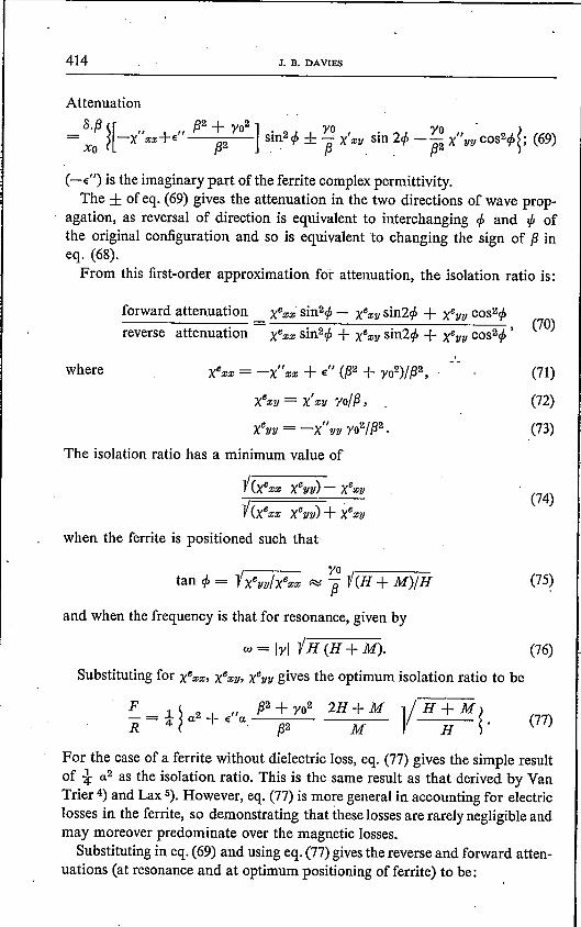
Attenuation
S.{3~[" " {32+ r02] . rO,. rO ,,' ~= -x Xx+€ sm2 ef> ± --'x xy sm 2ef> - - x yy cos2ef>; (69)Xo {32 {3. . (32
forward attenuation XBxx' sin2ef>- XBxy sin2ef>+ XByy cos2ef>reverse attenuation = XBxx sin2ef>+ XBXY sin2ef>+ Xeyy cos2ef>' (70)
(-€") is the imaginary part of the ferrite complex permittivity.The ± of eq. (69) gives the attenuation in the two directions of wave prop-
agation, as reversal of direction is equivalent to interchanging ef> and '" ofthe original configuration and so is equivalent to changing the sign of {3ineq. (68).From this first-order approximation for attenuation, the isolation ratio is:
where xBzz = -X"xx + €" ({32+ ro2)/{32,
X6XY = X'Zy ro/{3,
XByy = -X"yy ro2/{32.
The isolation ratio has a minimum value of
(71)
(72)
(73)
i(xexx XByy) - XBxy
i(xexx XByy) + XBXY
when the ferrite is positioned such that:
(74)
(75)
and when the frequency is that for resonance, given by
w= Irl "VH(H+M). (76)
Substituting for XBzz, XBxy, XByy gives the optimum isolation ratio to be
For the case of a ferrite without dielectric loss, eq. (77) gives the simple resultof i a2 as the isolation ratio. This is the same result as that derived by VanTrier 4) and Lax 5). However, eq. (77) is more general in accounting for electriclosses in the ferrite, so demonstrating that these losses are rarely negligible andmay moreover predominate over the magnetic losses.
Substituting in eq. (69) and using eq. (77) gives the reverse and forward atten-uations (at resonance and at optimum positioning of ferrite) to be:

NON-RECIPROCAL RESONANT ISOLATORS 415
reverse attenuation8.f3 4x6zz X611Yxo XBZZ + X6yy
8.f3 47T2M -vH(H + M)= -. ; (78)
Xo a(7T2[ M + H] + f32xo2 H) (2H +M) .
forward attenuation
Some of the limiting factors on the attenuation ratio can now be seen. Thefirst term of eq. (77) represents a limit due to magnetic damping in the ferriteand the second term describes the limitation due to electric loss in the forwarddirection.The bandwidth of the isolator in the reverse direction can be obtained by
observing that the loss terms of the effective susceptibility tensor all have thesame frequency dependence near resonance (that of K given by eq. (30)) andso, electric losses being negligible in the reverse direction, the attenuation mustalso have a maximum ofthat frequency dependence. From eq. (30) we have thatthe bandwidth for half peak attenuation is given by:
bandwidth = alyl(2H +M). (80)
Expressing the bandwidth in terms of the applied field gives
bandwidth (in oersteds) = 2 a wllyl. (81)
The form of the attenuation near resonance in the forward direction is dif-ferent to that in the reverse direction for two reasons. Firstly because electriclosses vary very slowly with frequency compared with magnetic losses and onlycontribute substantially to the forward attenuation. Secondly because the for-ward attenuation near resonance is (by eq. (69)) the difference between twolarge figures and whilst these figures share a common denominator that variesrapidly near resonance, they have numerators that vary differently with fre-quency. This small difference between two quantities is critically dependent onthe ferrite being correctly placed in the waveguide.
5.3. The second-order solutionWhen the perturbation of the waveguide fieldsdue to the presence of the ferrite
slab is no longer sinall, it is necessary to consider terms of the power series(eq. 56)) beyond the second. The third term is found for eq. (56) by evaluatingthe effective susceptibility tensor components at resonance (eqs (29) and (30)),substituting in eqs (64), (65), (66) and (75), then substituting again into eqs (60),

416 J. B. DAVIES
(61), "(62),(63) and (68) and so obtaining the required derivative given by eq.(58). This involved procedure emphasizes the difficulties in attempting any-thing beyond the small-perturbation (first-order) solution, Unfortunately thegeneral investigation, such as has been made of the first-order solution, is anintractable problem for a second or higher-order solution. However, to give anindication of the range of validity of the first-order solution, the second-ordersolution is now given for a typical configuration and ferrite. Only the reverseattenuation is evaluated, with the ferrite in the position of optimum isolationratio for a vanishingly thin ferrite sliver. Parameters for the ferrite are based(without any claimed accuracy) on Mullard ferroxcube T950, which is a nickel-copper ferrite.The following values are assumed:
M .....:.2800 OeWres = 9280.Mc/sa = 0·035Xo = 0'02286m
H= 1745 OeIrlerr = 3·2 Mc/s Oe
€ = 11{3o = ro = 137·5 m-1
Fig. 2
.From these figures are derived:
phase propagation constant = (137·5+ 1.091.1058 + 7.05.10782) m-1;attenuation constant = (1.1.1058- 1.003.10882) nepers m-1•
Changing the units of attenuation, and taking the sliver thickness 8 in thou-sandths of an inch, we derive the following:
attenuation = 0'616 8 - 0'0143 82 dB/in.
This relation is shown graphically in fig. 2.
0.005 0.0/0 0.015' 0.020 0.025Ferrite Ihickness (in)_3316
6. The small elliptical cylinder of ferrite mounted longitudinally in rectangularwaveguide
The isolation ratio has been derived in sec. 5 for the ferrite slab, the resultdescribing limitations due to the intrinsic magnetic damping and dielectric

NON-RECIPROCAL RESONANT ISOLATORS 417
losses within the ferrite. Making the ferrite height less than that of the wave-guide will reduce these dielectric losses which will be at a minimum when theheight is vanishingly small compared with the waveguide height and ferritewidth. If, on the other hand, the ferrite width is not vanishingly small comparedwith the waveguide width, then not all the ferrite will be at the position foroptimum isolation ratio (given by eq. (75», and the ratio will be non-optimum.These two restrictions on ferrite dimensions present a problem in isolator design,since a practical isolator requires a finite cross-section area of ferrite. A com-promise between the requirements of small height and width must therefore befound.To analyse this problem, a study has been made of an elliptical cylinder of
ferrite so that the effect of ferrite proportions on isolation ratio can be evalu-ated. The ellipse is chosen as the only cross-section for which one can definedemagnetizing factors, although the analysis is complicated by this shape ofarea of integration. The cross-section area of the cylinder has to be small com-pared with that ofthe waveguide in order that the perturbation formula (eq. (46»can be employed in the analysis. A ratio oft % or less should be suitably small.
6.1. Derivation of isolator performance
The configuration is shown in fig. 3.The ferrite cross-sect~on has ~rea LlA which is assumed to be very small com-
Fig.3

418 J. B. DAVIES
pared with the waveguide cross-section area A. The unperturbed fields are:
H» = F i f3 sin 7tXl t!(wt-{3Y) ,
Xo
7T 7TXlHy = F - cos - t!(wt-{3y) ,xc xc
where
. 7TXlEz = F i W /LOsin - t!(wt-{3Y) ,
Xo
Ex = Ey = Hz = 0,7T2
w2 /Lo eo =- + f32,x02
(82)
7TXl 7T2/L0 7TXl 7TXl
J )f32/LOXXX sin2 - + -- Xyy cosê - + W2/L02eOçzz Sin2-!Xo x02 Xo Xo
W
. (if37T if37T ). 7TXl 7TXl± - /LOXxv - - /LOXyx sm - cos -«lA Xo Xo Xo Xo
dA
and xi is the distance from the waveguide wall.~p.en the perturbation formula of eq. (46) can be applied to give
7TXlf 2w /LOf3 sin2 - dAA Xo
f3 f ~[ w2 /LOso s - 1 ]. 7TXl=A ? Xxx + f32 '. 1 + -Nz(e'- 1) sm2
~ +«lA
7T2XYy 7TXl i7T • 27TXl+ -- cosê - ± - Xxy sm -- dA. (83)f32 x02 xc f3xo xn
The alternative signs of ± give the.change in propagation constants in thetwo directions of propagation. Taking the negative of the imaginary part ofthis expression gives the attenuation as
:;;Lf3 f ~ 7TXl 7TXl 27TXl ~Xexx sin2 - + Xeyy COS2 -- ± Xexy sin -- dA
Xo Xo Xo(84)
«lA
where" " w2 /LOeO 1
Xexx = -X xx + e -------f32 {I + Nz(e' - 1)}2'
,Xxy -,
f3xo
7T
(85)

, NON-RECIPROCAL RESONANT ISOLATORS 419
e' is the real part of the dielectric constant e. .The integration in eq. (84) being over the ferrite cross-section, the distance Xl
is now evaluated for the element of ferrite E E of fig. 3:
CXl = X + - cos 8 .
2(86)
Noting that dA = t bc sin28 d8 we now proceed from eq. (84):TT
. bcf3 ~ f' . 2 7T Cattenuation = - Xezz sm2 8 sm - (x + - cos8) d82A xo 2
oTT ,
f 7T C+ Xeyy sin28 cosê - (x +- cos8) d8Xo 2
oTT
± xezy f sin28 sin 27T (x +~cos8) d8 ~. (87)xo 2 ~
oNowTT 7T C TT 27T Cf sin28 sin2 - (x + - cos8) d8 = t f {sin28- sin28 cos - (x + - cos8)} d8o Xo 2 0 Xo 2
7T TT 27TX (CX ) 27TX (C7T )= - -! f sin28 {cos - cos - cos8 - sin - sin - cos8 } d8.4 0 Xo Xo xo xe
(88)
TT C7TBy inspection I sin28 sin (- cos8) d8 = 0,
o xo
and by an ~ntegràl formula of Poisson:
(89)
TT (C7T) 2xo . (7TC)f 'sin28 cos - cos8 d8 =- r CV r Ct) J: -o xo 7TC Xo
xo (7TC)= - J1 - ,C Xo
(90)
where Ji (z) is the Bessel function ofthe first kind and first order.
Therefore
TT 7T C 7T Xo (7TC) 27TXf sin28 sin2 - (x + - cos8) d8 = --- Jt. - cos-o xc 2 4 2c Xo Xo
= ~~1 - cos 2;; [1- t (:] 2] } ,taking the first two terms only of the Bessel-function expansion. The followingintegrals are evaluated in a similar way:
J sin28 cosê ~ (x + ~cos8) d8 =~S 1·+ cos 27TX [1- t (C7T)2] l, (92)o xo 2 4 ? Xo Xo S
(91)
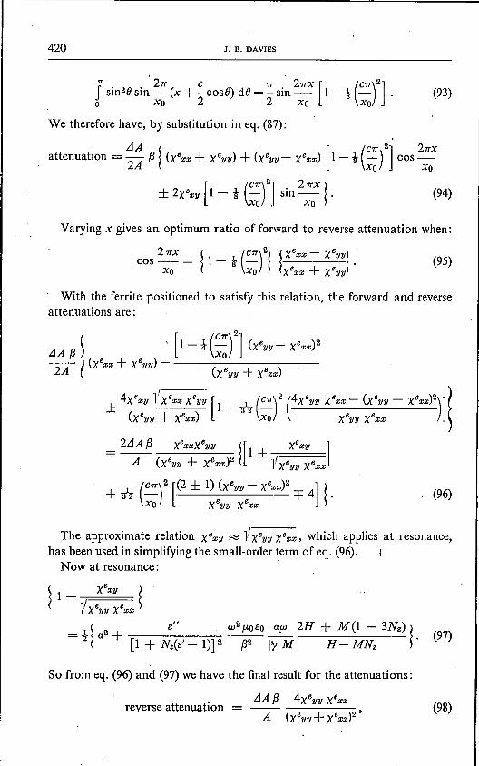
420 J. B. DAVIES
, .." 27T C 7T 27TX [ (C7T)2]I sin2e sin - (x + - cosë) de = - sin - 1 - t - .o xo 2 2 xo xo
(93)
We therefore have, by substitution in eq. (87):
Varying x gives an optimum ratio of forward to reverse attenuation when:
(95)
With the ferrite positioned to satisfy this relation, the forward and reverseattenuations are:
. (96)
The approximate relation XeXY R::: iXeyy xexx, which applies at resonance,has been used in simplifying the small-order term of eq. (96).
Now at resonance:
(97)
So from eq. (96) and (97) we have the final result for the attenuations:
LlA f3 4Xeyy xexx
A (xeyy + Xexx)2 'reverse attenuation = (98)

NON-RECIPROCAL RESONANT ISOLATORS 421
forward attenuationreverse attenuation
= ~t!l _ e" w2p.oeo ~ 2H + M(l - 3Nz)t (. -i {I + Nz(e' - 1)}2 f32 lylM H - MNz
(99)
The first two terms of this last expression have already been derived for thethin 'sliver (cf. eq. (77)) and with the three terms we associate intrinsic mag-netic losses, electric losses, and "additional magnetic losses", respectively.The last term expresses the degradation of performance due to some of the :ferrite not lying in the position for optimum isolation ratio.We wish to examine the effect of ellipse shape on isolation ratio and so must
derive the ratio explicitly in terms of a single parameter describing ellipse shape ..The ferrite being an ellipsoid with one axis of (assumed) infinite length, the
demagnetizing factors have the simple form
Nz = bj(b + c), Ny = 0, Nz = cj(b + c), (100)
where band c are the axis lengths in the z and x directions, respectively. Nzwill then be a suitable parameter describing ellipse shape.
Substitution in eq. (31) gives
H2 + H M (b - 2c)j(b + c) = M2 c(b - c)j(c + b)2 + w2jy2. (101)
Taking the appropriate root:
H = {Mj2(b + c)} {lb2 + [2(b + c)wjlyIM)2 + E2c- b)}. (102)
Some simplification is effected by considering the case
i.e. when for the unperturbed waveguide, the wavelength in the waveguide isi2times the free-space wavelength. Any deviation from this particular frequencywill alter final results by at most the same order ofproportion as the frequencyvariation.Equations (98) and (99) now take the form:
reverse attenuationLlA,BlyIM LlA 2R,B
~ [IYIM b 12 ~= A a (1 + R2Nz2)'
Aaw 1+2w(b+c)
(103)
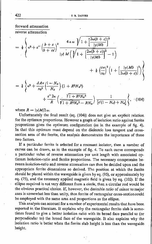
422 J. B. DAVIES
forward attenuationreverse attenuation
l 4aw 1/ [2wCb + C)]2= t a2+ e" ( b + C )2 V 1+ IrlMb
b + ce' . (1/ [2wCb + C)]2 )IrlM 1+ -1.lrlMb
+ t (CTr)2 (1 + [___l!~]2) (Xo 2w(b + c) ~
where R = IrIM/2w.Unfortunately the final result (eq. (104» does not give an explicit relation
for the optimum proportions. However a graph of isolation ratio against ferriteproportions gives the optimum configuration (as in the example of fig. 4).In that this optimum must depend on the dielectric loss tangent and cross-section area of the ferrite, the analysis demonstrates the importance of thesetwo factors.If a particular ferrite is selected for a resonant isolator, then a number of
curves can be drawn, as in the example of fig. 4. To each curve correspondsa particular value of reverse attenuation per unit length with associated op-timum isolation-ratio and ferrite proportions. The necessary compromise be-tween isolation-ratio and reverse attenuation can then be decided upon and theappropriate ferrite dimensions so derived. The position at which the ferriteshould be placed within the waveguide is given by eq. (95), or approximately byeq. (75), and the necessary applied magnetic field is given by eq. (l02). If theellipse required is not very different from a circle, then a circular rod would bethe obvious practical choice. If, however, the desirable ratio of minor to majoraxes is somewhat less than unity, then ferrite of rectangular cross-sectioncouldbe employed with the same area and proportions as the ellipse.This analysis can account for a number of experimental results that have been
reported in the literature. It explains why the rectangular ferrite slab is some-times found to give a better isolation ratio with its broad face parallel to (orperpendicular to) the broad face of the waveguide. It also explains why theisolation ratio is better when the ferrite slab height is less than the waveguideheight.
NON-RECIPROCAL RESONANT ISOLATORS 423
As the analysis can account for the dependence of isolator performance onferrite proportions, it partially amends the complete lack of theory on thisproblem pointed out by Clarricoats, Hayes and Harvey 9).
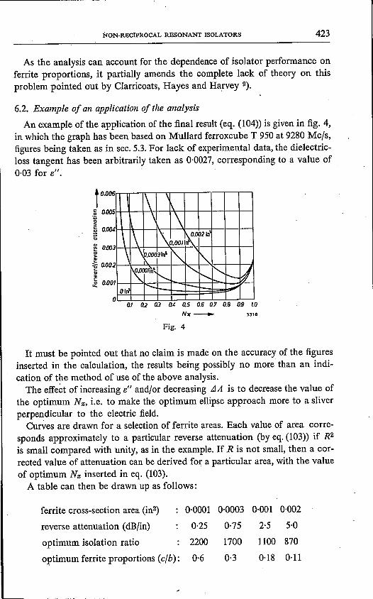
6.2. Example of an application of the analysisAn example of the application of the final result (eq. (104» is given in fig. 4,
in which the graph has been based on Mullard ferroxcube T 950 at 9280 Mc/s,figures being taken as in sec. 5.3. For lack of experimental data, the dielectric-loss tangent has been arbitrarily taken as 0,0027, corresponding to a value of0·03 for 13".
t 0.006.ê 0.005'ö"~ O.(J(U'ö~ 0.003'",.'"~ 0.002
~~ 0.00
I 1\,
\ \\ 1\ 1\ ~OO2In'
0.0011
\ \ p_OO03In' Î' '"l\.
I"M\<, <,r--..... I'--I'-- IJ
IOl~
["": ;-- ::.;;.
o0./ Q2 G.3 tu 0.5 0.6 0.7 0.8 OS /.0
NlC_ 3318
Fig.4
It must be pointed out that no claim is made on the accuracy of the figuresinserted in the calculation, the results being possibly no more than an indi-cation of the method of use of the above analysis.
The effect of increasing 13" and/or decreasing JA is to decrease the value ofthe optimum Nr;, i.e. to make the optimum ellipse approach more to a sliverperpendicular to the electric field.
Curves are drawn for a selection of ferrite areas. Each value of area corre-sponds approximately to a particular reverse attenuation (by eq. (103» if R2is small compared with unity, as in the example. If R is not small, then a cor-rected value of attenuation can be derived for a particular area, with the valueof optimum Nz inserted in eq. (103).A table can then be drawn up as follows:
ferrite cross-section area (in'') 0-0001 0-0003 a-OOI 0-002
reverse attenuation (dB/in) 0-25 0·75 2·5 5·0
optimum isolation ratio 2200 1700 1100 870
optimum ferrite proportions (c/b): 0·6 0·3 0-18 0-11

424 'J. B. DAVIES
The greatest area shown (0·002 in2) is approximately t % of the waveguidearea, so that the perturbation theory applied should be valid for all the valuesgiven.N.B. In the above analysis it has been assumed that the distance of the ferritefrom each waveguide broad face is much greater than the ferrite transversedimensions. The images of the ferrite formed in the broad faces will then havenegligible effect on the microwave field in the ferrite.
6.3. Some relations concerning demagnetizing factors
The demagnetizing factors of the general ellipsoid are expressed in terms ofelliptic integrals but reduce to the very simple form of eq. (100) for the case of anelliptical cylinder. From these relations is derived eq. (102) which can be ap-plied generally to resonant isolators. It gives the necessary applied magneticfield if the ferrite insert length is much greater than its other dimensions. Fromthis equation can be derived the following equation for the internal magneticfield:
Hint = {M/2(b + c)} {"V b2 + [2(b + c) w/lrIM] 2 - b}. (106)These equations may be applied to small rectangular cylinders with reason-
able accuracy, taking b : c as the ratio of ferrite dimensions parallel and per-pendicular to the static magnetic field.
Equation (106) can be used to verify that the ferrite is saturated in any par-ticular configuration. One canalso find the lower limit of frequency allowingmagnetic saturation from the equation:
Wmin = Irl -V-n.-sa-t-:{-M-s-at-:b--:-/("""b-+-c"-) -+-H,-sa-:t}-. (107)
7. The ferrite slab with dielectric backing plate
An attempt is made in this section to account for some of the results ob-tained experimentallyon ferrite slabs with adjacent dielectric slabs. Though themajority of experimentation has not been with full-height slabs, this configu-ration has been chosen to give a reasonably tractable problem.
The configuration of the waveguide cross-section is given in fig. 5.
z6 Il.
Fig.5
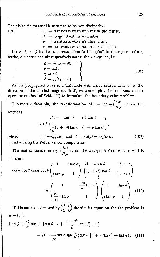
NON-RECIPROCAL RESONANT ISOLATORS 425
The dielectric material is assumed to be non-dissipative.Let ao = transverse wave number in the ferrite,
f3 = longitudinal wave number,yo = transverse wave number in air,u = transverse wave.number in dielectric.
Let cp, 0, TJ, ifl be the transverse "electrical lengths" in the regions of air,ferrite, dielectric and air respectively across the waveguide, i.e,
cp = YO(Xl - a),0= ao15,TJ = uLl,ifl = YO(X2 - Ll).
(l08)
As the propagated wave is a TE mode with fields independent of z (thedirection of the applied magnetic field), we can employ the transverse matrixoperator method of Seidel J") to formulate the boundary-value problem.
/ The matrix describing the transformation of the vector (Ez) across the,Hy
ferrite is
(
1- v tan 0)
cos 0 i~ (1 + v2) tan 0
i ~ tan 0 )
(1 + vtan 0) ,
where (109)
f.L and K being the Polder tensor components.
The matrix transforming (!:) across the waveguide from wall to wall is
therefore
(1 i tan CP) (1 - v tan 0 i ~ tan 0)
coscp cosO cosç cosifl i(l + v2) tan 0i~ncp 1 l+v~nO
~
X (ly'U
o
1 i :0 tan TJ) (1 i tan ifl). (110)
tan TJ 1 i tan ifl 1
If this matrix is denoted by (~ ~) the secular equation for the problem is
B = 0, i.eyo 1+ v2
{tan ifl + - tan TJ} {tan 0 [v + -- tan cp] -I}u ~
u= {I - - tan ifl tan TJ}{tan 0 [~ + v tan cp] + tan cp}. (111)
yo .

426 J. B. DAVIES
It is required to derive the propagation constant as a function of the thicknessof ferrite and of dielectric. f3 can be expressed as a doubly infinite power seriesin 8 and LI:
<Xl <Xl
f3 = I I f3mn 8m Llnm=O n=O
(112)
and for the fust order approximation in 8:co <Xl
f3 R:iI f30n Lln + 8I f3ln Lln . (113)o o
As the dielectric is non-dissipative, the fust series of eq. (113) must be real.The attenuation is therefore:
<Xl df3- Im S 8 \' f3ln Lln 2 = - 8Im[-] •
? ~ S . as 8=0
"-(~14)
df3 aodyo f3 do f3-=-- -=--df3 YO' df3 u
(116)
The secular eq. (111) can be put in the form:
yo ug(f3,8) _ {tan é + tan cp + - tan 7J - - tan cp tan'" tan 7J}
u yo
'1 + v2 -+ tanOg+ v [tancp-tan"'] ---~ -tancptan"'}
~v yo vu ~u yo(l +v2) ~
-tanO tan » - +- tan é tan'" +- tan'" + tan ë =0. (115)u yo YO. u~
Since (ao2 + (32), (Y02 + (32) and (0'2 + (32) are all independent of 8, LIand f3,the following relations exist:
dao f3
To derive df3jd8,the partial derivations è:Jgjè:Jf3 and è:JgjM are obtained fromeqs (108), (115) and (116): ' .
-.!!_ [Xl sec2 cp tan'" + (X2 - LI)sec2 '" tan cp] ~,Y02
(117)
[è:Jg] ~ Xl sec2cp+ (X2 - LI)sec2 '" LIsec27J (Y02 ) ~- = -f3 + - - tancp tan'"bp 6=0 yo yo 0'2
NON-RECIPROCAL RESONANT ISOLATORS 427
[bg] u- = yo sec2cp{~ tanifi tan'YJ-l}ba 8=0 yo
1+ v2+ aO{~+ v(tan cp - tan ifi)- ~ tan é tan é}
~vyo vu ~u (1 + v2)yO ~
-aotan'YJ -+-tancptanifi+-tanifi+ tan é ] • (118)u yo yo ~u,
Therefore
[df3] '. aoyo S[~+ v(tancp _ tanifi)- 1 + v
2tan é tanifi _ yo sec2cp]
do 8=0 f3D? ~ ao
[vyo vu ~u yo(1+' v2) u ] ~- tan 'YJ - + - tanë tanifi + - tanifi + , tanë - - sec2cp tanifi ,
. u yo yo u~ ao(119)
Y02where D = {Xl sec2 cp + (X2 - LI) sec2 ifi + LI secê 'YJ (- - tan cp tan ifi)
u2
U Y02 Y02+ tan'YJ- [(1--)(-+ tan ë tan ë) - yo (Xl sec2cptanifiY02 u2 u2
+ (X2 .; LI) secê ifi tan cp)]} • (120)
In eqs (117) to (120) and the following, ao, f3, YO,u and their related ex-pressions are all evaluated at 0 = 0, i.e. are the values for the waveguide loadedonly with the dielectric slab. This slab being non-dissipative, f3, yo, u, cp, 'YJ andifimust all be real, as must, also be D. .
From eq. (119):
[df3] yo yo uIm - = - {[tan cp - tanifi - - tan » - - tan ë tanifi tan'YJ] Im(aov)do 6=0 f3D u yo
+ [1- ~ tan ç tan ifi] Im(ao~)-tan cp [tan ifi+ yo tan 'YJ] Im (ao(1+v2»)l. (121)
yo u ~ , SFrom eqs (64), (65) and (66):
Im(ao~) = yo x" yy ,
Im(aov) = -f3 X'Zy,
(122)
(123)
(ao(1 + v2») 1 ""Im =- {_(f32 + Y02)s + f32x zz}.z . yo
(124)
Equation (121) now takes the form:
Im [df3] =_i {[I .:": tan » tan ifi] Xeyy - tan cp [tan ifi+ yo tan 'YJ] xezzdo 8=0 D yo u
. yo u+ [tan cp - tan ifi- - tan-, - - tan cp tan ifi tan 'YJ] XeXY}, (125)
u yo

428 J. B. DAVIES
where Xezz, Xezy and Xeyy are defined by eqs (71) to (73).Putting £J = ° in eq. (111) gives the relation
u yo[1 - - tan ljJ tan 7)] = - cot cp [tan ljJ +- tan 7]] (126)
yo u
by means of which eq. (125) reduces to
f3 sec2 cp u-- {I - - tanljJtan»]D yo
X {xezz sin2 cp + XeZy sin2 cp + Xeyy cosê cp}. (127)
The ratio of forward to reverse attenuations is now derived:
Ill! fdf3
] =d ê 6=0
F =~xezz sin2 cp - Xezy sin2 cp + Xeyy cos2 cp ~ •R ? xezz sin2 cp + XeZy sin2 cp + Xeyy cos'' cp S
(128)
This has a minimum value when (129)
This position can (theoretically) be realized since Xeyy and xezz are positive.At this position the ratio is given by eq. (74). At the resonant
frequency the ratio is given by eq. (7·7). In this equation, the onlyfactor dependent on the dielectric backing is f3 in the denominator of thesecond term. This gives the result that the dielectric backing plate has no effecton the isolation ratio if the ferrite electric loss is negligible, but improves theratio if ferrite electric loss is significant. This result is subject only to the ferritethickness being small compared with the waveguide width.The isolation ratio may now be given to a first-order approximation in the
die!ectric slab thickness:
f31 and Yl are the values of f3 and yo when LI = 0, i.e. for guide with onlyvanishingly thin slabs of ferrite and dielectric.Having examined the effect of a dielectric backing plate on isolation ratio,
the next study to follow from eq. (127) is of the effect on reverse attenuation.A convenient figure to study is the ratio of reverse attenuations with and without. backing plate. The comparison must clearly be made with the ferrite positionedalways in the position for optimum isolation ratio, which position will dependon the thickness of dielectric. Therefore when calculating the reverse attenuationas a function of zl, then - xi, X2, f3, yo, £J, cp, ljJ and 7]must all be regarded asfunctions of LI.

NON-RECIPROCAL RESONANT ISOLATORS
~attenuation with backing plate, at optimum position ~
Let feLl) = . _(131)attenuation without backing plate, at optimum position
From eq. (127):2
-Xo (tan if!+ yo tan 7]) {3(x" xx sin2 4>- X' xV yo sin2 4>+X"VV'!.:!_ cos" 4»feLl) = a {3 {32
{31(x" xxsin24>1- X' XV Y1 sin2 4>1+X"VV.!!. coS24>I){31 (312
(132)al and 4>1are the values of a and 4>when Ll= 0, i.e. for guide with only vanish-ingly thin slabs of ferrite and dielectric.
We wish to study the function feLl) for thin dielectric slabs and so employthe Taylor series expansion:
D sin 4>cos 4>
We therefore require
feLl) = 1+ Ll ['df] + O(Ll2).
dzl .<1=0
df 'è:Jf 'è:Jf d{3dLl = 'è:JLl+ 'è:J{3dLl '
where the derivative d{3/dLlarises from the restriction
{3tan 4>= yo ix" Vv/x" xx·
Differentiating eq. (135) with respect to {3gives
,1 ti "r x xx X xxd{3 yod{3
Differentiation of eq. (132) gives
['è:Jf] (a12-Y12)~Sin24>1 ~- = -- + (X2 - xi) tan4>l ,'è:J.Ll.<I =0 TT Y1
['è:Jf] = ,{31 {xo _ 2X2 sin24>1}
ö {3 .<I =0 Y1 sm 4>1cos 4>1
l" .2.J. I {31'n2 .J. ,,(2{312 + Y1
2) 2 .J. lX xx sin 'f'1+ Xxv - SI 'f'1 - X Vu cos 'f'l
Y1 {312
[dx2 {31X1] [( " "Y1
2) . I· Y1 ]+Y1{31 ---- . X xx-X vu- sm24>1-Xxu- COS24>1d{3 y2 fh2, {31+ 2'
{31{x" xx sin2 4>1- X' XV Y1 sin2 4>1+ X"uu ~ cos'' 4>1}. {31 {312.
d{3/dLlis derived by differentiating eq. (126) totally with respect to .Ll:
429
(133)
(134)
(135)
(136)
(137)
(138)
430 J. B. DAVIES
[dfJ] 0'12 - ')'12 •- = Sm2c/>1'dzl .<1=0 fJ~xo .
Substitution in, and considerable manipulation of eqs (134) and (136) to(139) gives the result:
(139)
[ df] 0'2 - ')'2
dLi .<I=0= fJxo (fJ2 x" xx + ')'2 x"vv) X
~2Q2 ,j 11 " + (fJ2 + ')'2) 11 (')'2X" vv - fJ2x" xx) ~ (140)I-' X2 r X xx x VV Q X VV 2 11 + Q2 11 •
I-' vrx v» I-'Xxx
The suffix 1 is now omitted from fJ1, ')'1, 0'1, it now being assumed that allfigures are evaluated in the limit as a and LI tend to zero.
As electric losses are negligible in the reverse direction, we can take the ratiox"vvlx"xx to be (H + M)IHat the resonantfrequency.
Noting that (141)
where 81is the permittivity of the dielectric, we have finally that at resonance:
LI(81- 1)f(LI) = 1+ S M')'2 l X
Xo ? H + (fJ2 + ')'2) S
I X2 ,j ) (fJ2 + ')'2) (H + M) [H(')'2 - fJ2) +M')'2] ~27T- y H(H + M + .xn fJ2 H(')'2 + fJ2) +M')'2 .
(142)
This relation takes the following simpler form for the particular, though com-mon case when fJ = ')',i.e. when the wavelength in the empty wavegulde is i2times the free-space wavelength:
LI ( H + M) S X2 1/ H M lf(LI) = 1+ Xo (81- 1) 4 2H + M l7T Xo V H + M + 2H + MS'
Equation (142) predicts that the effect of a thin dielectric backingplateis to increase the attenuation of an isolator in both' directions, the increasebeing smaller in the forward direction.
By interchanging xi for X2 in the above analysis, we can also say that theincrease is greater when the dielectric is nearer to the centre of the guide thanis the ferrite. This is in àgreement with experimental results 8) 10). . .
Since the ratio x" vvlx" xx varies slowly with frequency in the neighbourhoodof resonance, eq. (140) predicts that the multiplying factor f(LI) varies slowlywith frequency, - i.e. that the shape of the attenuation curves near resonanceare substantially the same for ferrite with or without dielectric backing plate.Itmight be noted that almost all practical values of H and M give a value be-tween 4 and 6 for the expression .
(143)

NON-RECIPROCAL .RESONANT ISOLATORS 431
4(2:::) C~21/H:M+ 2H: M)'The multiplying factor is then given approximately by:
f(,1) = 1+ 5(Sl - 1).tJ/xo. (144)
Wefinallyconsider how the analysis ofthis section accounts for the improvedisolation ratios obtained in various experiments cited in the literature 7)~) 10). Three reasons can be put forward for these improvements. Firstly ithas been shown that the dielectric backing plate enhances the isolation ratio ifthere is significant electric loss in the ferrite. The improvement, however, is notlikely to be very great. Secondly the addition of the backing plate increasesthe reverse attenuation, and so to achieve a particular reverse attenuation asmaller cross-section area offerrite can be used. This reduction of area improvesthe isolation ratio that can be achieved (by the results of sec. 6), for exampleby reducing the ferrite height and hence the ferrite electriè loss. Thirdly it mustbe pointed out that invariably the slabs offerrite and dielectric used experimen-tally have not been full height. For partial-height slabs the placing of the dielec-tric material alongside the ferrite increases the effective depolarizing factorin the "z" direction, and so reduces the ferrite electric losses.
8. Conclusions
The performance of the resonant isolator has been derived for rectangularwaveguide containing various configurations of ferrite. The analyses attemptto explain and evaluate the working of the resonant isolator, and to provideguidance in certain aspects of isolator design.The difficulties and limitations of these analyses are typical of boundary-
value problems without exact solutions. Many practical ferrite configurationscan be implicitly solved exactly, as for example the problems studied in secs5 and 7. However in such cases the required explicitsolutionmustbe anapprox-imate solution: a solution in the form of a convergent infinite series is for-mally exact, but numerically only approximate. This report presents pertur-bation solutions for the various geometries studied, and so gives results thatare tractable only for small volumes of ferrite. The perturbation method be-comes tedious in its complexity when the perturbation becomes large, and forsuch a case it would be more fruitful to employ the variational method.
Mullard Research LaboratoriesSalfords, England
Salfords, March 1960
432 J. B. DAVIES
REFERENCES
1) B. D. H. Tellegen, Philips Res. Repts3, 81-101,1948.2) C. L. Hogan, Bell Syst. tech. J. 31,1-31,1952.3) M. L. Kales, H. M. Chait, and N. G. Sakiotis, J. appl. Phys. 24, 816-817, 1953.4) A. A. Th. M. van Trier, unpublished report.5) B. Lax, Proc. Inst. Radio Engrs 44, 1368-1386, 1956, p. 1377.0) B. Lax, Proc. Inst. Radio Engrs 44,1368-1386, 1956, p. 1385.7) H. G. Beljers, private communication.S) M. T. Weiss, Trans. Inst. Radio Engrs, MTT-4 No. 4,240,1956.9) P. J. B. Clarricoats, A. G. Hayes and A. F. Harvey, Proc. Instn elect. Engrs 104 B,
278, 1957.10) R. M. Godfrey, B. L. Humphreys, P. E. V. Allin and G. Mott, Proc. Instn elect.
Engrs 104 B, 356, 1957.11) F. Bloch, Phys. Rev. 70,460-474,1946.12) N. Bloembergen, Phys. Rev. 78, 572-580,1950.13) L. La nda u and L. Lifshitz, Phys. Z. Sowjet 8,153-169,1935.14) D. Polder, Phil. Mag. 40, 99-115, 1949.15) C. Kittel, Phys. Rev. 73, 155-172, 1948.10) B. Lax, Proc. Inst. Radio Engrs 44, 1368-1386, 1956, p. 1370.17) H. Seidel, J. appl. Phys. 28, 218-226, 1957.