Embed Size (px)
Citation preview
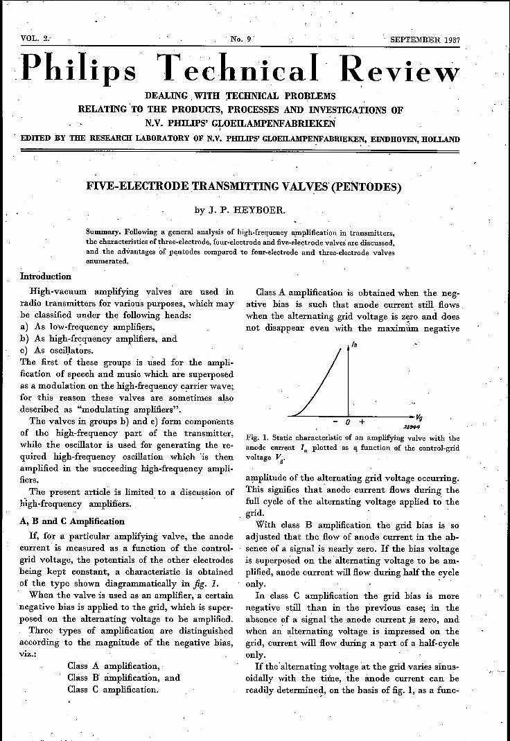
VOL .. 2; , No. 9 SEPTEMBER 1937
Philips ReviewDEALING. WITH )'ECHNICAL PR01,)LEMS
RELATING' TO THE PRODUCTS, PROCESSES AND INVESTIGATIONS OFN.V. PHILIPS' GLOEILAMPENFABRIEKEN,
EDITED BY THE RESEARCH LABORATORY OF N.V. PIDLIPS' GLOEILAMPENFABRIEKEN, EINDHOVEN, HOLLAND. ,
FIVE-ELECTRODE TRANSMITTING VALyES' (PENTODES)
by J. P. HEYBOER.
Summary. Following a general analysis of high-frequency amplification in transmitters,the characteristics of three-electrode, four-electrode and five-electrode valves'are discussed,and the advantages of pentodes compared to four-electrode and three-electrode valvesenumerated.
Introduetion
High-vacuum amplifying valves are used inradio transmitters for various purposes, which maybe classified under the following headsra) As low-frequency amplifiers,b) As high-fr~quency amplifiers, andc) As oscillators,The first of these groups is U:sed for the ampli-fication of speech and music which are superposedas a modulation on the high-frequency carrier wave;for this reason these valves are sometimes alsodescribed as "modulating amplifiers".The valves in groups b) and c) form components
of the high-frequency part of the transmitter,while the oscillator is used for generating the re-quired high-frequency oscillation which 'is thenamplified in the succeeding high-frequency ampli-fiers.
The present article is limited to a discussion ofhigh-frequency amplifiers., .
A, Band C Amplification
If, for a particular amplifying valve, the anodecurrent is measured as a function of the control-grid voltage, the potentials of the other electrodesbeing kept constant, a characteristic is obtainedof the type shown diagrammatically in fig. 1.When the valve is used as an amplifier, a certain
.negative bias is applied to the grid, which is super-posed on the alternating voltage to be amplified.
Three types of amplification are distinguishedaccording to the magnitude of the negative bias,viz.:
Class A amplification,Class B amplification, andClass C amplification.
L__ .. __ ....
, ,
Class A amplification is obtained when the neg-ative bias is such that anode current still flowswhen the alternating grid voltage is z~ro and doesnot disappear even with the maximum negative
la _'
.......:::...._------!:o-+-:------ Vg2ZS44
Fig. 1. Static characteristic of an amplifying valve with theanode current la plotted as I! function of the control-gridvoltage Vg'
amplitude of the alternating grid voltage occurring.This signifies that' anode current flows during thefull cycle of the alternating voltage applied to' thegrid.
With class B amplification the grid bias is soadjusted that the flow of anode current in the ab-sence of a signal is nearly zero. If the bias voltageis superposed on the 'alternating voltage to be am-plified, anode current will flow during half the cycleonly. .
In class C amplification the grid bias is morenegative still than in the previous case; in theabsence of a signal the ·anode current js zero, andwhen an' alternating voltage is impressed on thegIid, current will flow during a part of a half-cycleonly.If the' alternating voltage at the grid varies sinus-
oidally with' the time, 'the anode current can bereadily determined, on the basis of fig. 1, as a func-
258 PHILIPS TECHNICAL REVIEW VOL. 2, No. 9
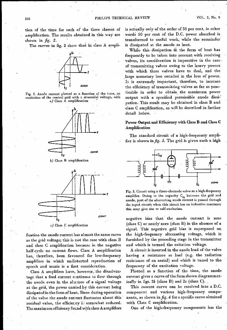
tion of the time for each of the three classes ofamplification. The results obtained in this way areshown in fig. 2. .
The curves in fig. 2 show that in class A a;mpli-
Ja
Z2S45t
Fig. 2. Anode current plotted as a function of the time, onexcitation of the control grid with a sinusoidal voltage, with
a) Class A amplification '
Ia
tb) Class B amplification
Ja
__-+--11·I 22S47
tc) Class ~ amplification
fication the anode current has almost the same curveas the grid voltage; this is not the case with class Band class C amplification because in the negativehalf-cycle no current flows. Class A amplificationhas, therefore, been favoured for low-frequencyamplifiers in which undistorted reproduetion ofspeech. and music is a first consideration.
Class A amplifiers have, however, .the disadvan-tage that a feed current c orrtinues to flow throughthe anode even in the absence of a signal voltageat the grid, the power carried by this current beingdissipated in the form of heat. Since during operationof the valve the anode current fluctuates about this'residual value, the efficier.cy i j~ somewhat reduced.The maximum efficiency found with class A amplifiers
,is actually only of the order of 50 per cent, in otherwords 50 per cent of the D.C. power absorbed is.transformed to useful work,' while the remainderis dissipated at the anode as heat.
While this dissipation in the form of heat hasfrequently to he taken into account with receivingvalves, its considerarion is imperative in the case·of transmitting valves owing to the heavy powerswith which these valves have to deal, and the_large monetary loss entailed in .the loss of power.It is extremely important, therefore, to increasethe efficiency of transmitting valves as far as prac-ticable in order to obtain the maximum poweroutput with a specified permissible anode dissi-'pation. This result may be obtained in class Bandclass C amplification, as will be described in furtherdetail below.
Power Output and Efficiency with Class B and Class CAmplification
The standard circuit of a high-frequency ampli-fier is shoIDI infig. 3. The grid is given such a high
Fig. 3. Circuit using a three-electrode valve as a high-frequencyamplifier. Owing to the capacity Ca8 between the grid andanode, part of the alternating anode current is passed throughthe input circuit; when this circuit has an inductive reactancethis may give rise to self-excitation.
negative bias that' the anode current is zero(class C) or nearly" zero (class B) in the absence of asignal. This negative grid bias is superposed onthe high-frequency alternating voltage, which isfurnished by the preceding stage in the transmitterand which is termed the exitation voltage.A circuit is inserted in the anode lead of the valve
having a resistance as load (e.g. the radiation'resistance of an aerial) and which is tuned to thefrequency of the excitation voltage,
Plotted as a function of the time, the anodecurrent gives a curve of the form shown diagrammat-ically in figs. 2b (class B) and 2c (class C)..
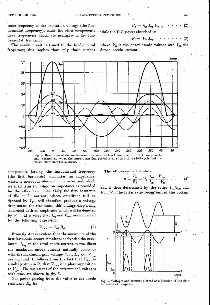
This current curve can he resolved into a D.C.component and various high-frequency compo-nents, as shown in fig. 4 for a specific curve obtainedwith Class C amplification.
One of the high-frequency components has the
SEPTEMBER 1937 TRANSMITTING PENTODES 259
same frequency as the excitation voltage (the fun-damental frequency), while the other componentshave frequencies which are multiples of the fun-damental frequency.The anode' circuit is tuned to the fundamental
frequency; this implies that only diose current
(2)Po= 1/2 lal Va~,while the D.e. power absorbed is:
Pi = Va lao, (3)where Va is the direct anode voltage and lao thedirect' anode current.
1,0....---.------., r---",.....-::---r-Iam --r----T-......--....---r---~,(~.\~' ,OPI-+-------hl/I---l--\--I-\ ~-I-+---I--+-I-I-I/ ~\-+---+-.,...j\o.6·~+---~---4--~~--4----+----~--+---~--_'----~~~_'~~,~--~~
280 o 80 120 160 200 240 280 320 360 40 80,40320Fig. 4. Resolution of the anode-current curve of a class e amplifier into D.e. componentsand harmonics. when the current-carrying period is one third of the full cycle and thevalve characteristic is linear. .
components having the fundamental frequency(the' first harmonic) encounter an impedance,which is moreover ohmic in character and which 'we shall term Ra, while no impedance is providedfor the other harmonics. Only thè first harmonicof the anode current, whose amplitude will bedenoted by Iai, will therefore produce a voltagedrop across the resistance, this voltage drop being, sinusoidal With an amplitude which will be denoted.by Va~' It is clear that lal and Va~ are connectedby the following expression:
Va~ = lal Ra (1)
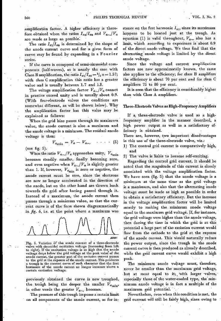
. From fig. 4 it is evident that the maximum of thefirst harmonic occurs simultaneously with the max-imum Ia on the total anode-current curve. Sincemrhe maximum anode current naturally coincideswith the maximum grid voltage Vg~, ia1 and Vg~are cophasal. It follows from the fact that Va~ isa voltage drop in Ra that Va~ is in phase oppositionto Vg~' The variations of the currents and voltageswith time are shown in fig. 5. ,
The power passing from the valve to the anoderesistance Ra is:
The efficiency is therefore:Po lal' r.;
17 = - = 1/2,_, -; (4)Pi lao Va
and is thus determined by the ratios Ial/1ao andVa~/Va, the latter ratio being' termed the voltage
Fig. 5. Voltages and currents plotted as a function of the timefor a class e amplifier.
260 P1I1LIPS TECHNICAL REVIEW vOL. 2, No. 9
amplificatión factor. A higher efficiency is there-fore obtained when the ratios lalflao and Va~/Vaare made as large as possible:
The ratio lal/lao is determined by the shape ofthe anode current curve and for' a given form ofcurve may be found by expanding in a F 0 u l' ierseries.If the curve is composed of semi-sinusoidal com-
'ponents (half-waves), as is nearly the case withCI~ss B amplification, the ~atio l~l!I ao=1/2n= 1.57;with class C amplification this ratio has a greatervalue and is usually' between 1.7 and 1.8.
The voltage amplification factor Va~/Va cannotin practice exceed unity and is usually about 0.9.(With four-electrode valves the conditions aresomewhat different, as will be shown below). Whythe amplification factor has this value may beexplained as follows:
When the grid bias passes through its maximumvalue, the anode current is also. a maximum andthe anode voltage is a minimum. The residual anodevoltage is then:
Vamin = Va - Va~ . (5)(see fig. 5).
When the ratio Va~/Va approaches unity, Va .rmnbecomes steadily smaller, finally becoming zero,and even negative when Va~/Va is slightly greaterthan 1. If, however, Va . is zero or negative, the= ,anode current must be zero, since the electronsare now no 'longer accelerated in the direction ofthe anode, but on the other hand are thrown backtówards the grid after having passed through it.Instead of a maximum, the anode current thenpasses through a minimum value, so that the cur-rent curve is of the 'form shown diagrammaticallyin fig. 6, i.e. at the point where a maximum was
/1 1\ ft J!\. AA~,
Fig. 6. Variation óf the anode current of a three-electrodevalve with sinusoidal excitation voltage (increasing from leftto right). If the excitation voltage is so high that the anodevoltage drops below the grid voltage at the peak valué of theanode current, the greater part of the emission current passesto the grid at the expense of the anode current. This producesa trough in the current curve of such character that the firstharmonic of the anode current no longer increases above acertain excitation voltage.
previously obtained the curve is now troughed,the troügh being the deeper the smaller Vu . ,. rmnin other words the greater Va~ becomes.
The presence of this trough imposes a'certain limiton all components of the anode current, as for in-
stance on the first harmonic lal' since its maximumhappens' to he located just at the trough. Asequation (1) is valid throughout, Va"" also has alimit, which according to experience is' about 0.9of the direct anode voltage. We thus find that thealternating 'anode voltage is limited by the directanode voltage.
Since the voltage and current amplificationfactors are now approximately known, the samealso applies to the efficiency; for class B amplifiersthe efficiency is about 70 per cent and for class Camplifiers 75 to 80 per cent. "It is seen that the efficiency is considerably higher
tha~ with Class A amplifiers.
Three-Electrode Valves as High-Frequency Amplifiers
If a_ three-electrode valve is used as a high-frequency amplifier in the manner described, ahigh power output as well as a satisfactory ef-ficiency is obtained.There are, however; two important disadvantagesin this use of the three-electrode valve, viz.:1) The control grid current is comparatively high,
and2) The valve is liable to become self-exciting,, Regarding the control grid current, it should benoted that the magnitude of this current is closelyassociated with the voltage amplification factor.We have seen (fig. 5) that the 'anode voltage is a.minimum at the same time as the grid voltageis a maximum, and also that the alternating ~nodevoltage must be made as high as possible in orderto obtain a satisfactory efficiency. But the increasein the voltage' amplification factor will be limitedmerely to making the minimum anode voltageequal to the maximum grid voltagè. If, for instance, 'the grid voltage were higher than the anode voltage,then during the time in which the grid is at this,potential a large part of the emission current wouldflow from the cathode to the grid at the expenseof the anode current. This would naturally 'reducethe power output, since the trough in the anodecurrent curve is then produced as already described,while the grid' current curve would exhibit a highpeak. .
The minimum anode voltage must, therefore,never be smaller than the maximum' grid voltage,.bu~ at most equal to it;, with larger 'valves,'especially those of the water-cooled type, the' min-nimum anode voltage is in fact a multiple of themaximum grid potential. . ",
Nevertheless, even when this condition is met, thegrid current will still he fairly high,. since owing to
SEPTEMBER 1937 TRANSMITTING PENTODES 261
the periodically low anode voltage the acceleratingaction of the anode is small and hence the proh-ability 'of electrons reaching the grid is com-paratively high.The grid current power, the socalled excitation
power, is hence relatively high with' a three-elec-trodé valve and must be furnished by 'the pre-ceding stage. It will be seen below that screen gridvalves have more satisfactory characteristics inthis direction.The liability to become self-exciting is due to the
capacity.hetween the grid and anode, shown as Cagin fig. 3, because the alternating anode voltageinduces a curr~nt in the series circuit made up ofCag and the grid circuit, whereby an alternatingvoltage is applied to the latter. If the impedancein the grid circuit is inductive, this feed-backvoltage will be in phase opposition to the alternatinganode voltage and hence just cophasal with theinitial excitation voltage. In certain circumstances,the feed-back voltage at a given alternating anodevoltage can thus become equal to the excitationvoltage required to produce this alternating anode.voltage; self-excitation then results.This disadvantage of. high-frequency three-
electrode amplifiers can. be eliminated in one oftwo ways:1) By neutrodyning, i.e. applying a voltage to
the grid which is equal to the feed-back voltagebut in phase opposition to it.
2) Inserting an auxiliary grid between the anodeand control grid, which is earthed on the high-frequency side, so that a screening action isproduced between the a~ode and the controlgrid, and Cag is thereby made very small.
Four-Electrode Valves
The latter method is used in four-electrode andfive-electrode valves which are fitted with a screengrid g2 between the control grid gl and the anode a.Experience has shown that neutrodyning can bedispensed with in these amplifying valves, as Cagl
is very small. The values of Cag! are given belowfor typical four-electrode valves, as well as thecorresponding values for two-three-electrode valvesfor purposes of comparison.
Four-~QC 05/15 Cag! = 0.004 (J.(J.F
electrode QB 2/75 Cagl = 0.02 (J.(J.Fvalves { QB 3/500 Cag! = 0.01 (J.(J.F
Three-
{ TC 04/10-1 Cag 6.8 (J.(J.Felectrodevalves TC i/75 Cag =10.4 (J.(J.F
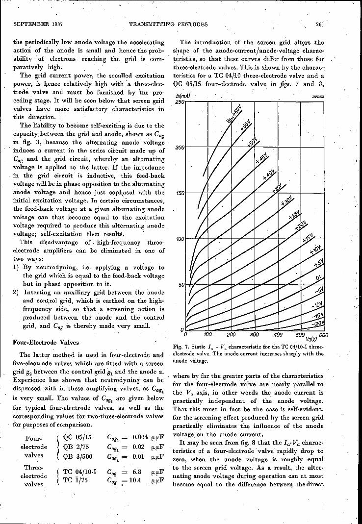
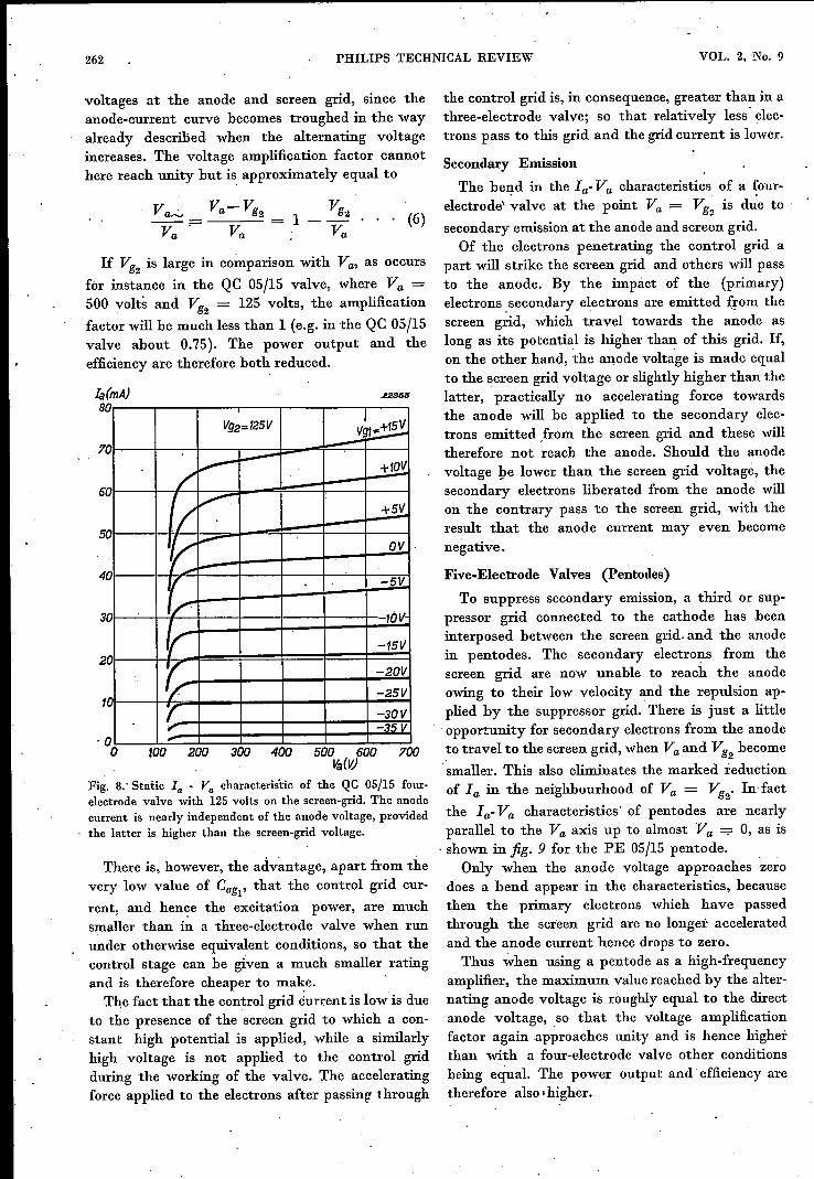
The introduetion of the screen grid alters thes~ape of the anode-current/anode-voltage charac-teristics, so that these curves differ from those forthree-electrode valves. This is shown by the charac-:teristics for a TC 04/10 three-electrode valve and aQC 05/15 four-electrode valve in figs. 7 and 8,
là(mA)250r---------r---------~--------.---------._--------._--------,
22352
500 Va(V) 600
Fig. 7. Static la - Va characteristic for the TC 04/10-1 three-electrode valve. The anode current increases sharply with theanode voltage.
where by far the greater parts of the characteristicsfor the four-electrode valve are nearly parallel tothe Va axis, in other words the, anode current ispractically independent of the anode voltage.That this must in fact be the case IS self-evident,for the screening effect produced by the screen gridpractically eliminates the influence of the anodevoltage, on the anode current.
It may be seen from fig. 8 that the Ia- Va charac-teristics of a four-electrode' valve rapidly drop tozero, when the anode voltage is roughly equal
. to the screen grid voltage.' As a result, the alter-nating anode voltage during operatien can at mostbecome equal to the difference hetween the direct
262 PHILIPS TECHNICAL REVIEW VOL. 2, No. 9
voltages at the anode and screen grid, since theanode-current curve becomes troughed in the wayalready described when the alternating voltageincreases. The voltage amplification factor cannothere reach unity but is approximately equal to
Vg.). . . (6)
Va
If Vg2 is large in comparison with Va, as occurs
for instance in the QC 05/15 valve, where Va =500 volts and Vg2 = 125 volts, the amplification
factor will be much less than l(e.g. in the QC 05/15valve about 0.75). The power output and theefficiency are therefore both reduced.
Ia (mA)8
.uSt5lS
6i
0 IVg2=125V
~~'0 -
/'~+1~
'0
(/V +~
~J...o- DV
0_,.. i"'"
v -5V
'01/
-1DV
1/ -15V'0 /' -2DV
1/ -25V" r. -3DV
~ -35V0
5'0
4
3
2
1
a tDO 2'0'0 300 400 500 6'00 700vaM
Fig. 8.' Static la - Va characteristic of the QC 05/15 four-electrode valve with 125 volts on the screen-grid. The anodecurrent is nearly independent of the anode voltage, providedthe latter is higher than the screen-grid voltage.
There is, however, the advantage, apart from thevery low value of Cag1, that the control grid cur-
rent, and hence the excitation power, are muchsmaller than in a three-electrode valve when rununder otherwise equivalent conditions, so that thecontrol stage can be given a much smaller ratingand is therefore cheaper to make, .The fact that the control grid current is low is due
to the presence of the screen grid to which a con-stant high potential is applied, while a similarlyhigh voltage is not applied to the control gridduring the working of the valve. The acceleratingforce applied to the electrons after passing through
the control grid is, in consequence, greater than in athree-electrode valve; so that relatively less' elec-trons pass to this grid and the grid current is lower.
Secondary Emission
The bend in the Ia- Va characteristics of a ~our-electrode' valve at the point Va = Vg2 is due tosecondary emission at the anode and screen grid.
Of the electrons penetrating the control grid apart will strike the screen grid and others will passto the anode. By the impact of the (primary)electrons. secondary electrons are emitted from thescreen grid, which travel towards the anode aslong as its potential is higher than of this grid. If,on the other hand, the anode voltage is made equalto the screen grid voltage or slightly higher than thelatter, practically no accelerating force towardsthe anode will be applied to the secondary elec-trons emitted .from the screen grid and these willtherefore not reach the anode. Should the anodevoltage ye lower than the screen grid voltage, thesecondary electrons liberated from the anode willon the contrary pass to the screen grid, with theresult that the anode current may even becomenegative.
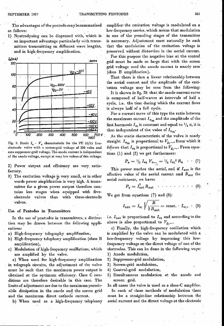
Five-Electrode Valves (Pentodes)
To suppress secondary emission, a third or sup-pressor grid connected to the cathode has .beeninterposed between the screen grid. and the anodein pentodes. The secondary electrons from thescreen grid are now unable to reach the anodeowing to their low velocity and the repulsion ap-plied by the suppressor grid. There is just a little.opportunity for secondary electrons from the anodeto travel to the screen grid, when Va and Vg become. 2smaller. This also eliminates the marked reductionof la in the neighbourhood of Va = Vg2• In·fact
the Ia- Va characteristics' of pentodes are nearlyparallel to the Va axis up to almost Va --:-0, as is. shown in fig. 9 for the PE 05/15 pentode.
Only when the anode voltage approaches 'zerodoes a bend appear in the characteristics, becausethen the primary electrons which have passedthrough the screen grid are no longer acceleratedand the anode current hence drops to zero.Thus when using a pentode as a high-frequency
amplifier, the maximum value reached by the alter-nating anode voltage is roughly equal to the directanode voltage, so that the voltage amplificationfactor again approaches unity and is hence higherthan with a four-electrode valve other conditionsbeing equal. The power output and efficiency aretherefore also Ihigher.
SEPTEMBER 1937 TRANSMITTINGPENTODES
amplifier the excitation voltage is modulated on aluw-frequency carrier, which means that modulationin one of the preceding stages of the transmitteris necessary. Adjustment must naturally be suchthat the modulation of the excitation voltage ispreserved 'without distortion in the aerial current.
For this purpose the negative bias at the controlgrid must be made so large that with the screengrid voltagc used the anode current is nearly zero(class B amplification).That there is then a linear relationship between
the aerial current and the amplitude of the exci-tation voltage may be seen from the following:
It is shown in fig. 2b that the anode current curveis composed' of half-waves at intervals of half acycle, i.e. the time during which the current flowsis always half of a full cycle.
For a current curve of this type the ratio betweenthe maximum current Iam and the amplitude of the
first harmonic lal is constant and equal to 1/2 n, it is,o thus independent of the value of lam·o tOO 200 300 400 500 600Va{VJ
OOv . As the static characteristic of the valve is nearly
Fig. 9. Static la _ Va characteristic for the PE 05/15 five- straight lam is proportional to VgI~' from·which it .electrode valve with a screen-gridvoltage of 300 volts and fo~lows that lal is proportional to VgI~. From equa-zerosuppressor-gridvoltage. Theanodecurrent is independent tions (1) and (2) we get furthermore:of the anodevoltage,exceptat very lowvaluesofthisvoltage.
The advantages of the pentode may he summarisedas follows:1) Neutrodyning can be dispensed with,' which is
an important advantage particularly with trans-mitters transmitting on different wave lengths,and in high~frequency amplification.
!a(mA)120
100'VQl~~OV
-::.-- Vg2=300V
I Vg3=OV -40V
·1,
-60V,
C -BOV
-tODV,..- -120V- -1.d, 'v
80
60
40
20
2) Power output and efficiency are very. satis-fuctmy. .3) The excitation voltage is very small, or in other,.
words power ainplification is very high. A trans-mitter for a given power output therefore con-tains less stages when equipped with five-electrode valves than with three-electrodevalves.
Use of Pentodes in Transmitters -In the use of pentodes in transmitters, a distinc-
tion may be drawn between the following appli-cations:a) High-frequency telegraphy amplification,b) High-frequency telephony amplification (class B
amplification),c) Modulation of high-frequency oscillations, which
are amplified by the valve.a) When used for high-frequency amplification
in telegraph circuits, the adjustment of the valvemust be such that the maximum power output isobtained at the optimum efficiency. Class C con-ditions are therefore desirable in this case. Thelimits of adjustment are due to the maximum permis-sible dissipation in the anode and the screen gridand the maximum direct cathod~ current.
l?) When used as a high-frequency telephony
Po = 1/2 lal Va_ = 1/2 Ia12 Ra . . (7)~.".
This power reaches the aerial, and if Iant is theeffective value of the aerial current and Raat theaerial resistance, we have:
2Po = Iant Ra11t . . . . . (8).
We get from equations (7) and (8):
i»:Iant = lal )/-- = const .. lal' . (9)
2Rant
i.e. I ant is proportional to Ial and according to theabove is also proportional to VgI~.
c) Finally, the high-frequency oscillation whichis amplified by the va:lve can be modulated with alow-frequency voltage by impressing' this low-frequency voltage on the direct voltage of one of theelectrodes. This can be done in the following ways:1) Anode modulation,2) Suppressor-grid modulation,3) Screen-grid modulation,4) Control-grid modulation,S) Simultaneous modulation at the anode and
screen grid.In all cases the valve is used as a class-C amplifier.
In each of these methods of modulation theremust be a straight-line relationship between theaerial current and the direct voltage at the electrode
263
264. PHILIPS TECHNICAL REVIEW VOL. 2, No. 9
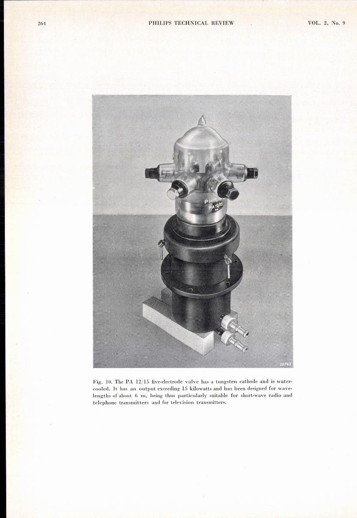
Fig. 10. The PA 12/15 five-electrode valve has a tungsten cathode and is water-cooled. It has an output exceeding 15 kilowatts and has been designed for wave-lengths of about 6 rn, being thus particularly suitable for short-wave radio andtelephone transmitters and for television transmitters.
SEPTEMBER 1937 TRANSMITTING PENTODES 265
on which the modulation voltage is impressed, sincethe modulation must be reproduced without dis-'tortion. It has been found in practice that a satis-factory' linear relationship is readily obtainableby methods 1), 2) and 5), but that this is difficultwith 3) and, 4).In modulation at the suppressor grid, the fact
is used that the .anode current is the smaller thehigher the negative voltage applied to the suppressorgrid. This is due to the partial rejection by thenegative suppressor grid of the slower electrons,so that, not all the electrons reach the anode.The' relationship between the aerial current and
the suppressor grid voltage has been found satis-factorily linear' so that good modulation may he'obtained. A particular advantage found withmodulation at the suppressor grid is that no powerfor modulation is required, for since the suppressorgrid remains negative throughout modulation nocurrent flows to this grid. The modulator can there-fore be made small even with the largest of thefive-electrode valves, e.g. the PC 3/1000.
Properties of the Philips Transmitting Pentode
Philips manufacture the following five-electrodetransmitting valves:PE 05/15, OC 05/15, PC 1/50, PE 1/80, PC 1.5/100"PC 3/1000 and PA 12/15. The power outputs ofthese valves lie between 15 watts with the firstvalve over 15 kilowatts with the last valve. Ofthese valves PE 05/15 and PE 1/80 have indirectly-heated cathodes, PA 12/15 has a tungsten cathodeand the other valves a directly-heated oxidecathode. The PA 12/15 transmitting valve is water-cooled and is shown in fig. la.
It has already been ,'seen that the control gridcurrent in these valves is very small as comparedwith that in three-electrode valves, and that theexcitation power also is hence much smaller., A comparison is made in the following tablebetween the TC 1/75 three-electrode valve and thePC 1.5/100 five-electrode valve, the data relatingto the so-called telegraph adjustment, i.e. at which
, the valves give their highest output.
TC 1/75 PC1.5/100
Anode voltage. . . VaControl-grid voltage VglScreen-grid voltage . Vg2Suppressor-grid voltage . Vgs
Anode current. . . laControl-grid. cur~ent 19lScreen-grid current. 19aExcitation voltage . Vgl
Excitation power. . Ph!Anode power input . Pi~Anode dissipation . . ~}' PaScreen-~d dissipation .: ,~',Pg2High-frequency power output:::PoAnode efficiency. . . . " -:~~~'Ja
. power output . . . ',' PoRatio --:---:--------'
, excitation power .• ' ;.~Ph!Capacity between anode anl':" .control 'grid , . . . . . ~~~Cagl /10.4 {.l.{.l.F0.03 {.l.{.l.F
1500 V 1500 V-160 V -200, V
300 V0 V
123 mA 145 mA12 mA 3.5 mA
50 mA ..240 V 280 V ;':;if~2:9 W 1.0 W185 W 218 W .!:~~J
-n , ..
70 W 77 w ·;l~15 w115 W 141 W62.2 %, 65 % , "
40 141
It is seen from this table that the ratio of thepower output to the excitation power is 141 withthe five-electrode valve and 40 with the three-electrode valve, the five-electrode valve thushaving a marked advantage in this direction.