Embed Size (px)
Citation preview

Siemens LV 1 T · 2009
7
7
7/2 Introduction
SIMOCODE 3UF Motor Management and Control Devices
7/6 SIMOCODE pro 3UF7 motor management and control devices
7/32 3UF18 current transformers for overload protection
LOGO! Logic Modules7/37 General data7/38 LOGO! Modular basic versions7/39 LOGO! Modular pure versionsST 701) LOGO! Modular expansion modulesST 701) LOGO! Modular communication
modulesST 701) AS-Interface connection for LOGO!ST 701) LOGO! Contact7/40 LOGO! Software
3RP, 3RT19 Timing Relays7/41 General data7/46 3RP15 timing relays
in industrial enclosure, 22.5 mm7/52 3RP20 timing relays, 45 mm7/55 3RT19 16, 3RT19 26 timing relays
for mounting onto contactors
Monitoring Relays3UG Monitoring Relaysfor Electrical and AdditionalMeasurements
7/59 Line monitoring7/65 Voltage monitoring7/69 Current monitoring7/73 Power factor and active current
monitoringResidual current monitoring:
7/78 - Residual current monitoring relays7/83 - 3UL22 summation current
transformersInsulation monitoring:
7/84 - For ungrounded AC networks7/86 - For ungrounded DC networks
Level monitoring:7/88 - Level monitoring relays7/92 - Level monitoring sensors7/93 Speed monitoring
3RS10, 3RS11 Temperature Monitoring Relays
7/97 General data7/100 Relays, analogically adjustable,
for 1 sensor7/104 Relays, digitally adjustable,
for 1 sensor7/107 Relays, digitally adjustable,
for up to 3 sensors3RN1 Thermistor Motor Protection
7/110 For PTC sensors
3TK28 Safety Relays7/116 General data7/118 With electronic enabling circuits7/127 With relay enabling circuits7/138 With contactor relay enabling circuits7/143 With special functions
3RK3 Modular Safety Systems7/147 General data7/148 Modules
Interface Converters 7/155 3RS17 interface converters
1) See Catalog ST 70 · 2009 "Products for Totally Integrated Automation and Micro Automation".
Monitoring and Control Devices
LV1T_2009_Gesamtbuch_EN.book Seite 1 Donnerstag, 26. Februar 2009 2:00 14
© Siemens AG 2009

Monitoring and Control Devices
Introduction
7/2 Siemens LV 1 T · 2009
7
■ Overview
1) See Catalog ST 70 · 2009 "Products for Totally Integrated Automation and Micro Automation".
The advantages at a glance
Type PageSIMOCODE 3UF motor management and control devicesSIMOCODE pro 3UF7 • Compact, modular design
• Unique flexibility in terms of functionality and hardware configuration
• Wide functional range from the distributed I/O system to the autonomous motor management system
• All control functions from the direct-on-line starter to the pole-changing switch with reversing contactor
• All motor sizes• Integration in all PROFIBUS-capable automation systems• Application in low-voltage controlgear for motor control
centers in the process industry• Increases plant availability• Saves costs during construction, commissioning and
operation of the plant• Extensive data of the motor feeder available everywhere on
the PROFIBUS• All protection, monitoring and control functions for the motor
feeder in a single system
3UF7 7/6
3UF18 current transformers for overload protection
• Protection transformer for activating overload relays or for use with SIMOCODE 3UF
• Ensures proportional current transfer up to a multiple of the primary rated current
3UF18 7/32
LOGO! logic modulesLOGO! logic modules • Compact, user-friendly and low-cost solution for simple
control tasks• Universal:
- Building installation and wiring (lighting, shutters, awnings, doors, access control, barriers, ventilation systems ...)
- Control cabinet installation- Machine and device construction (pumps, small presses,
compressors, hydraulic lifts, conveyors ...) - Special controls for conservatories and greenhouses- Signal preprocessing for other controllers
• Flexible expansion depending on the application
LOGO! Modular basic versions • With display, pushbuttons and an interface for connecting expansion units
6ED1 052-1 7/38
LOGO! Modular pure versions
• Without display and pushbuttons but with an interface for connecting expansion units
6ED1 052-2 7/39
LOGO! Modular expansion modules • For connection to LOGO! Modular basic versions with digital inputs and outputs or analog inputs and outputs
6ED1 055-1 ST 701)
LOGO! Modular communication modules
• For integrating LOGO! in an instabus KNX EIB system or as an AS-Interface slave
6BK1 700,3RK1 400
ST 701)
LOGO! Power • Power supply for converting the mains voltage of 100 ... 240 V AC into an operational voltage of 24 V DC or 12 V DC
6EP1 3 ST 701)
LOGO! Contact • Switching module for switching resistive loads and motors directly
6ED1 057-4 ST 701)
LOGO! Software • For switchgear program generation on the PC 6ED1 058 7/40
3RP, 3RT19 timing relays3RP15 timing relays in industrial enclosure, 22.5 mm
• Low-cost solution with monofunctions such as response delay, off-delay, clock-pulse, wye-delta function and multi-function
3RP15 7/46
• Wide voltage range versions
3RP20 timing relays, 45 mm • The solution for small mounting depths 3RP20 7/52• The low mounting height reduces the tier spacing
3RT19 16, 3RP19 26 timing relays for mounting onto contactors
• Saves space because the relay is mounted onto the contactor
3RT19 16, 3RT19 26
7/55
• Wiring advantages thanks to direct contacting to the contactor
3UF7 3RP156ED1 052
LV1T_2009_Gesamtbuch_EN.book Seite 2 Donnerstag, 26. Februar 2009 2:00 14
© Siemens AG 2009

Monitoring and Control Devices
7/3Siemens LV 1 T · 2009
Introduction
7
The advantages at a glance
Type Page
3UG monitoring relays for electrical and additional measurementsLine monitoring
Phase sequence • Low-cost solution for monitoring the phase sequence 3UG45 11 7/59
Phase sequence, phase failure, phase unbalance • Wide voltage range from 160 ... 690 V 3UG45 12 7/59
Phase sequence, phase failure, phase unbalance and undervoltage
• Analogically adjustable• Wide voltage range from 160 ... 690 V
3UG45 13 7/60
• Digitally adjustable with LCD for indication of ACTUAL value and device status
• Wide voltage range from 160 ... 690 V
3UG46 14 7/60
Phase sequence, phase failure, phase unbalance over limit values, overvoltage and undervoltage
• Digitally adjustable with LCD for indication of ACTUAL value and device status
• Wide voltage range from 160 ... 690 V
3UG46 15 7/61
Phase sequence, phase and N conductor failure, phase unbalance over limit values, overvoltage and undervoltage
3UG46 16 7/61
Automatic correction of the direction of rotation in case of wrong phase sequence, phase failure, phase unbalance, overvoltage and undervoltage
3UG46 17 7/61
Automatic correction of the direction of rotation in case of wrong phase sequence, phase and N conductor failure, phase unbalance, overvoltage and undervoltage
3UG46 18 7/61
Voltage monitoring
Voltage monitoring with internal power supply for overvoltage and undervoltage
• Digitally adjustable with LCD for indication of ACTUAL value and device status
• Wide measuring ranges• Version for wide voltage range
3UG46 33 7/65
Voltage monitoring with auxiliary voltage for overvoltage and undervoltage
3UG46 31,3UG46 32
7/66
Current monitoring
Current monitoring with auxiliary voltage for overshoot and undershoot
• Digitally adjustable with LCD for indication of ACTUAL value and device status
• Wide measuring ranges• Version for wide voltage range
3UG46 21,3UG46 22
7/69
Power factor and active current monitoring (motor load monitoring)
Power factor and active current monitoring with internal power supply for overshoot, undershoot or window monitoring
• For load monitoring over the entire torque range• Digitally adjustable with LCD
for indication of ACTUAL value and device status• Wide voltage range from 90 ... 690 V
3UG46 41 7/73
Residual current monitoring
Residual current monitoring relays • Digitally adjustable with LCD for indication of ACTUAL value and device status
• Adjustable threshold values for warning and disconnection• For plant monitoring• Wide voltage range from 90 ... 690 V
3UG46 24 7/78
Summation current transformers • Detects fault currents in machines and plants 3UL22 7/83
Insulation monitoring
Monitoring of the insulation resistance for ungrounded AC or DC networks from 1 to 110 kΩ
• Test button 3UG30 81, 3UG30 82
7/84• With or without memory• Switchable measuring range
Level monitoring
Fill level and resistance • As single-step or two-step controls for inlet or outlet monitor-ing of conducting liquids or as resistance threshold switch
3UG45 01 7/88
• Adjustable, wide range from 2 ... 200 kΩ• UNDER/OVER adjustable
Level monitoring sensors • Wire, rod or bow electrodes 3UG32 7/92
Speed monitoring
Speed monitoring for overshoot, undershoot or window monitoring
• Digitally adjustable with LCD for indication of ACTUAL value and device status
• Wide measuring ranges• Version for wide voltage range• Together with a sensor for monitoring continuous pulses• With or without memory• Adjustable delay times
3UG46 51 7/93
3UG45 11 3UG46 16 3UG46 33
LV1T_2009_Gesamtbuch_EN.book Seite 3 Donnerstag, 26. Februar 2009 2:00 14
© Siemens AG 2009

Monitoring and Control Devices
Introduction
7/4 Siemens LV 1 T · 2009
7
The advantages at a glance
Type Page
3RS10, 3RS11 temperature monitoring relaysFor monitoring the temperatures of solids, liquids, and gases
Relays, analog adjustable, for 1 sensor • Separate versions for overshoot and undershoot 3RS10, 3RS11
7/100• For simple monitoring tasks• For PT100 or thermoelements J and K• Variable hysteresis
Relays, digitally adjustable, for 1 sensor • For two-step or three-step controls 3RS10, 3RS11, 3RS20,3RS21
7/104• For monitoring heat generation plants• For PT100/1000, KTY83/84, NTC or thermoelements
type J, K, T, E, N, R, S, B
Relays, digitally adjustable for up to 3 sensors • For simultaneously monitoring several sensors 3RS10 7/107• Especially suited for monitoring motor winding temperatures• For PT100/1000, KTY83/84, NTC
3RN1 thermistor motor protectionFor PTC sensors • Relays for monitoring motor winding temperatures with type
A PTC sensors3RN1 7/110
• Integrated with ATEX approval• Closed-circuit principle• Depending on the version: with short-circuit and open-circuit
detection, protection against voltage failure, manual/auto/remote RESET, 1 CO, 1 NO + 1 NC, 2 CO, 1 NO + 1 CO or 2 CO hard gold-plating
3TK28 safety relaysWith electronic enabling circuits • Permanent function checking
• No wear because switched electronically• High switching frequency• Long electrical endurance• Evaluation of solid-state sensors• Sensor lead up to max. 2000 m• Cascading possible• Insensitive to vibrations and dirt• Compact design, low weight• Approved for the world market
3TK28 4 7/118
With relay enabling circuits • Compact design• Floating safe outputs• Also suitable for press and punch controls• Can be used up to an ambient temperature
of max. 70 °C
3TK28 2, 3TK28 3
7/127
With contactor relay enabling circuits • Enabling circuits, floating• AC-15/DC-13 switching capacity• Protective separation• Long mechanical and electrical endurance• Certified as a complete unit• Fault minimization and cost reduction through factory wiring• Low installation costs
3TK28 5 7/138
With special functions • Floating safe outputs• Signaling outputs for status and diagnostic signals• Safe standstill monitoring
3TK28 1 7/143
3TK283RN13RS10
LV1T_2009_Gesamtbuch_EN.book Seite 4 Donnerstag, 26. Februar 2009 2:00 14
© Siemens AG 2009

Monitoring and Control Devices
7/5Siemens LV 1 T · 2009
Introduction
7
■ Options
On the following pages you will find selection tables for monitor-ing and control devices.
"Increased safety" type of protection EEx e/d according to ATEX directive 94/9/EC
The communication-capable, modularly designed SIMOCODE pro motor management system (SIRIUS Motor Management and Control Devices) protects motors of types of protection EEx e and EEx d in potentially explosive areas.
ATEX approval for operation in areas subject to explosion hazard
The SIRIUS 3RN1 thermistor motor protection relay for PTC sen-sors is certified according to ATEX Ex II (2) G and GD for gases and dust.
The SIRIUS SIMOCODE pro 3UF7 motor management system is certified for the protection of motors in areas subject to explosion hazard according to• ATEX Ex I (M2); equipment group I, category M2 (mining) • ATEX Ex II (2) GD; equipment group II, category 2 in area GD
See "Appendix" --> "Standards and approvals" --> "Type over-view of approved devices for potentially explosive areas (ATEX explosion protection)".
The advantages at a glance
Type Page3RK3 modular safety systemFreely configurable, modular safety relays • More functionality and flexibility through freely configurable
safety logic• For all safety applications thanks to compliance with the
highest safety requirements (Category 4 according to EN 954-1, Performance Level e according to ISO 13849-1 or SIL3 according to IEC 62061)
• Can be used globally• Modular hardware configuration • Parameterization by means of software instead of wiring• Removable terminals for greater plant availability
3RK3 7/147
3RS17 interface convertersConverters for standard signals and non-standard variables
• All terminals protected against polarity reversing and overvoltage up to 30 V
• For electrical separation and conversion of analog signals
• Short-circuit resistant outputs• From 6.2 mm width• Switchable multi-range converters• Versions with manual/automatic switch for setpoint selection• Versions for conversion of analog variables into frequency
3RS17 7/155
3RS173RK3
Screw terminals
Spring-type terminals
These connections are indicated in the Technical specifications by orange backgrounds.
LV1T_2009_Gesamtbuch_EN.book Seite 5 Donnerstag, 26. Februar 2009 2:00 14
© Siemens AG 2009

SIMOCODE 3UF Motor Management and Control Devices
SIMOCODE pro 3UF7 motor managementand control devices
7/6 Siemens LV 1 T · 2009
7
■ Overview
SIMOCODE pro V with current/voltage measuring module, expansion modules and operator panel with display
SIMOCODE pro is a flexible, modular motor management sys-tem for motors with constant speeds in the low-voltage perfor-mance range. It optimizes the connection between I&C and mo-tor feeder, increases plant availability and allows significant savings to be made for startup, operation and maintenance of a system.
When SIMOCODE pro is installed in the low-voltage switch-board, it is the intelligent interface between the higher-level au-tomation system and the motor feeder and includes thefollowing:• Multifunctional, solid-state full motor protection which is inde-
pendent of the automation system• Integrated control functions instead of hardware for the motor
control• Detailed operating, service and diagnostics data• Open communication through PROFIBUS DP, the standard for
fieldbus systems
SIMOCODE ES is the software package for SIMOCODEpro pa-rameterization, start-up and diagnostics.
■ Design
General
SIMOCODE pro is a modularly constructed motor management system which is subdivided into two device series with different functional scopes:• SIMOCODE pro C and• SIMOCODE pro V.
Both series (systems) are made up of different hardware compo-nents (modules):
Per feeder each system always comprises one basic unit and one separate current measuring module. The two modules are connected together electrically through the system interface with a connection cable and can be mounted mechanically con-nected as a unit (one behind the other) or separately (side by side). The motor current to be monitored is decisive only for the choice of the current measuring module.
An operator panel for mounting in the control cabinet door is op-tionally connectable through a second system interface on the basic unit. Both the current measuring module and the operator panel are electrically supplied by the basic unit through the con-nection cable. More inputs, outputs and functions can be added to basic unit 2 (SIMOCODE pro V) by means of optional expan-sion modules, thus supplementing the inputs and outputs al-ready existing on the basic unit.
All modules are connected by connection cables. The connec-tion cables are available in various lengths. The maximum dis-tance between the modules (e.g. between the basic unit and the current measuring module) must not exceed 2.5 m. The total length of all the connection cables in a single system must not be more than 3 m.
SIMOCODE pro designed for mixed operation
Depending on functional requirements, the two systems can be used simultaneously without any problems and without any ad-ditional outlay in a low-voltage system. SIMOCODE pro C is fully upward-compatible to SIMOCODE pro V. The same compo-nents are used. The parameterization of SIMOCODE pro C can be transferred without any problems. Both systems have the same removable terminals and the same terminal designations.
System SIMOCODE pro C SIMOCODE pro V
Modules • Basic unit 1 • Basic unit 2• Current measuring module • Current measuring module or
current/voltage measuring module
• Operator panel (optional) • Decoupling module (optional)
• Operator panel or operator panel with display (optional)
• Expansion modules (optional)
LV1T_2009_Gesamtbuch_EN.book Seite 6 Donnerstag, 26. Februar 2009 2:00 14
© Siemens AG 2009

SIMOCODE 3UF Motor Management and Control Devices
7/7Siemens LV 1 T · 2009
SIMOCODE pro 3UF7 motor managementand control devices
7
SIMOCODE pro C, basic unit 1
The compact system for • Direct-on-line and reversing starters • For actuation of a circuit breaker (MCCB)with up to 4 binary inputs, up to 3 monostable relay outputs and one thermistor connection (binary PTC)
The basic unit 1 is available in two different versions for the fol-lowing supply voltages:• 24 V DC• 110 ... 240 V AC/DC
SIMOCODE pro C, basic unit 1
Inputs:4 binary inputs, with internal supply from 24 V DC
Outputs:3 (2+1) monostable relay outputs
Thermistor connection for binary PTC
PROFIBUS interface:• 9-pole SUB-D or• Terminal connection
Connection of the supply voltage:• 24 V DC or• 110 ... 240 V AC/DC
Test/reset button
3 LEDs
2 system interfaces for connection of• a current measuring module and• an operator panel
Basic unit 1 is suitable for standard rail mounting or, with addi-tional push-in lugs, for fixing to a mounting plate.
SIMOCODE pro V, basic unit 2
The variable system which offers all SIMOCODE pro C functions plus many additional functions. Basic unit 2 supports the follow-ing control functions:• Direct-on-line and reversing starters• Wye/delta starters, also with direction reversal • Two speeds, motors with separate windings (pole-changing
switch); also with direction reversal • Two speeds, motors with separate Dahlander windings (also
with direction reversal) • Positioner actuation • Solenoid valve actuation • Actuation of a motor starter protector or circuit breaker
(MCCB)• Soft starter actuation (also with direction reversal)
Basic unit 2 has 4 binary inputs, 3 monostable relay outputs and one thermistor connection (binary PTC). The type and number of inputs and outputs can be increased by means of additional ex-pansion modules.
Basic unit 2 is available in two different versions for the following supply voltages:• 24 V DC• 110 ... 240 V AC/DC
SIMOCODE pro V, basic unit 2
Inputs:4 binary inputs, with internal supply from 24 V DC
Outputs:3 (2+1) monostable relay outputs
Thermistor connection for binary PTC
PROFIBUS interface:• 9-pole SUB-D or• Terminal connection
Connection of the supply voltage:• 24 V DC or• 110 ... 240 V AC/DC
Test/reset button
3 LEDs
2 system interfaces for connection of• a current measuring module or current/voltage measuring
module,• expansion modules and• an operator panel.
Basic unit 2 is suitable for standard rail mounting or, with addi-tional push-in lugs, for fixing to a mounting plate.
LV1T_2009_Gesamtbuch_EN.book Seite 7 Donnerstag, 26. Februar 2009 2:00 14
© Siemens AG 2009

SIMOCODE 3UF Motor Management and Control Devices
SIMOCODE pro 3UF7 motor managementand control devices
7/8 Siemens LV 1 T · 2009
7
Current measuring modules (current ranges)
The current measuring module is selected for each feeder ac-cording to the rated motor current to be monitored. Available for this purpose are various current measuring modules for current ranges from 0.3 ... 630 A. The current measuring module is con-nected to the basic unit by a connection cable and is supplied with electricity by the basic unit through this connection cable. Current measuring modules up to 100 A are suitable for stan-dard rail mounting or can be fixed directly to the mounting plate by means of additional push-in lugs. Similarly, current measuring modules up to 200 A can also be mounted on standard mount-ing rails or be fixed directly to mounting plates by means of fixtures integrated in the enclosure. Finally, current measuring modules up to 630 A can only be mounted with the integrated screw fixtures.
Note: Current measuring modules for up to 100 A current setting can be mechanically connected to the corresponding basic unit and mounted with it as a unit (one behind the other). For larger cur-rent measuring modules, only separate mounting is possible.
Current measuring modules for the following current ranges are offered:• 0.3 ... 3 A with straight-through current transformer• 2.4 ... 25 A with straight-through current transformer• 10 ... 100 A with straight-through current transformer• 20 ... 200 A with straight-through current transformer or bus-
bar connection• 63 ... 630 A with busbar connection
For motor currents up to 820 A, a current measuring module for 0.3 ... 3 A, for example, can be used in combination with a 3UF1 8 interposing/current transformer.
Current/voltage measuring modules (voltage range)
Current/voltage measuring modules have the same functions as the current measuring modules. However, they can only be used in combination with basic unit 2. They offer the same current ranges for the rated motor current. Mounting on standard mount-ing rails, on mounting plates or directly on the contactor is also the same as with the current measuring modules. They can also measure voltages up to 690 V in the main circuit, which is nec-essary for calculating or monitoring power-related measured variables. Current/voltage measuring modules have additional removable terminals, to which the voltages of all three phases of the main circuit are connected (3-pole). An additional 3-core cable can be used, for example, to directly connect the main cir-cuit from the busbar terminals of the current/voltage measuring modules to the voltage measuring terminals.
Note: Current/voltage measuring modules can only be mounted sepa-rately from the associated basic unit 2. If the current/voltage measuring module is used in non-grounded networks or in net-works with insulation measurement or monitoring, then a decou-pling module must be used in addition.
Sizes and current setting of the current measuring modules and the current/voltage measuring modules
Width
45 mm 55 mm 120 mm 145 mm
Current measuring modules
Current/voltage measuring modules
Current setting To measure and monitor motor currents up to 820 A, matching 3UF18 intermediate current transformers are avail-able for the current mea-suring modules and current/voltage measur-ing modules.
0.3 ... 3 A; 2.4 ... 25 A 10 ... 100 A 20 ... 200 A 63 ... 630 A
Straight-through transformers
Busbar connection
LV1T_2009_Gesamtbuch_EN.book Seite 8 Donnerstag, 26. Februar 2009 2:00 14
© Siemens AG 2009

SIMOCODE 3UF Motor Management and Control Devices
7/9Siemens LV 1 T · 2009
SIMOCODE pro 3UF7 motor managementand control devices
7
Decoupling module for current/voltage measuring modules
Decoupling module
If the voltage and power measuring module from SIMOCODE pro is used in non-grounded networks, then a decoupling mod-ule must be installed on the system interface upstream from each current/voltage measuring module. If the voltage and power measuring module from SIMOCODE pro is used in net-works with additional insulation measurement or insulation mon-itoring, then a decoupling module must be installed likewise up-stream from each current/voltage measuring module. If 3UF7 10 current-only measuring modules are used in these networks, then additional decoupling modules must not be used under any circumstances.
Note: When a decoupling module is used, restrictions on the number of connectable expansion modules must be observed (see page 7/13).
Operator panels
The operator panel is used to control the motor feeder and can replace all conventional pushbuttons and indicator lights to save space. This means that SIMOCODE pro or the feeder can be op-erated directly at the control cabinet and that the system inter-face is connected externally for easier parameterization or diag-nostics using a PC or programming device, for example.
The operator panel is connected to the basic unit over a connec-tion cable from its rear system interface and is supplied electri-cally from the basic unit.
The operator panel has 5 freely assignable buttons and a total of 10 LEDs, of which 7 LEDs can be used as required and as-signed to any status signal.
A PC or programming device can be connected to the front sys-tem interface over the PC cable.
The operator panel is mounted in the control cabinet door or the front plate of, for example, a withdrawable unit and satisfies de-gree of protection IP54 with the system interface covered.
Operator panel for SIMOCODE pro
• 10 LEDs• Test/reset button• 4 control keys• 2 system interfaces on the front with interface covers
LV1T_2009_Gesamtbuch_EN.book Seite 9 Donnerstag, 26. Februar 2009 2:00 14
© Siemens AG 2009
SIMOCODE 3UF Motor Management and Control Devices
SIMOCODE pro 3UF7 motor managementand control devices
7/10 Siemens LV 1 T · 2009
7
Operator panels with display
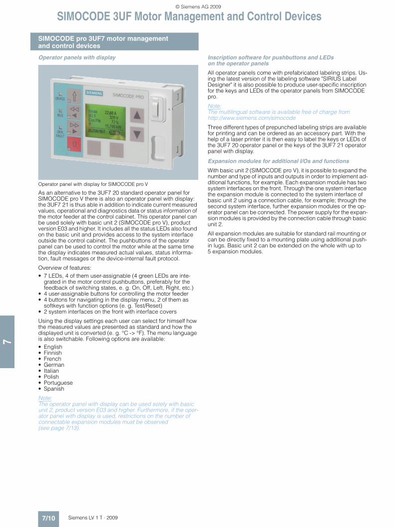
Operator panel with display for SIMOCODE pro V
As an alternative to the 3UF7 20 standard operator panel for SIMOCODE pro V there is also an operator panel with display: the 3UF7 21 is thus able in addition to indicate current measured values, operational and diagnostics data or status information of the motor feeder at the control cabinet. This operator panel can be used solely with basic unit 2 (SIMOCODE pro V), product version E03 and higher. It includes all the status LEDs also found on the basic unit and provides access to the system interface outside the control cabinet. The pushbuttons of the operator panel can be used to control the motor while at the same time the display indicates measured actual values, status informa-tion, fault messages or the device-internal fault protocol.
Overview of features:• 7 LEDs, 4 of them user-assignable (4 green LEDs are inte-
grated in the motor control pushbuttons, preferably for the feedback of switching states, e. g. On, Off, Left, Right, etc.)
• 4 user-assignable buttons for controlling the motor feeder• 4 buttons for navigating in the display menu, 2 of them as
softkeys with function options (e. g. Test/Reset)• 2 system interfaces on the front with interface covers
Using the display settings each user can select for himself how the measured values are presented as standard and how the displayed unit is converted (e. g. °C -> °F). The menu language is also switchable. Following options are available:• English• Finnish• French• German• Italian• Polish• Portuguese• Spanish
Note: The operator panel with display can be used solely with basic unit 2, product version E03 and higher. Furthermore, if the oper-ator panel with display is used, restrictions on the number of connectable expansion modules must be observed (see page 7/13).
Inscription software for pushbuttons and LEDs on the operator panels
All operator panels come with prefabricated labeling strips. Us-ing the latest version of the labeling software "SIRIUS Label Designer" it is also possible to produce user-specific inscription for the keys and LEDs of the operator panels from SIMOCODE pro.
Note: The multilingual software is available free of charge from http://www.siemens.com/simocode
Three different types of prepunched labeling strips are available for printing and can be ordered as an accessory part. With the help of a laser printer it is then easy to label the keys or LEDs of the 3UF7 20 operator panel or the keys of the 3UF7 21 operator panel with display.
Expansion modules for additional I/Os and functions
With basic unit 2 (SIMOCODE pro V), it is possible to expand the number and type of inputs and outputs in order to implement ad-ditional functions, for example. Each expansion module has two system interfaces on the front. Through the one system interface the expansion module is connected to the system interface of basic unit 2 using a connection cable, for example; through the second system interface, further expansion modules or the op-erator panel can be connected. The power supply for the expan-sion modules is provided by the connection cable through basic unit 2.
All expansion modules are suitable for standard rail mounting or can be directly fixed to a mounting plate using additional push-in lugs. Basic unit 2 can be extended on the whole with up to 5 expansion modules.
LV1T_2009_Gesamtbuch_EN.book Seite 10 Donnerstag, 26. Februar 2009 2:00 14
© Siemens AG 2009

SIMOCODE 3UF Motor Management and Control Devices
7/11Siemens LV 1 T · 2009
SIMOCODE pro 3UF7 motor managementand control devices
7
Expansion with additional binary I/Os through digital modules
Up to two digital modules can be used to add additional binary inputs and relay outputs to basic unit 2. The input circuits of the digital modules are supplied from an external power supply. The following versions are available:• 4 inputs, supplied externally with 24 V DC and 2 monostable
relay outputs• 4 inputs, supplied externally with 110 ... 240 V AC/DC and
2 monostable relay outputs• 4 inputs, supplied externally with 24 V DC and 2 bistable relay
outputs• 4 inputs, supplied externally with 110 ... 240 V AC/DC and
2 bistable relay outputs
Up to two digital modules can be connected to one basic unit 2. All versions can be combined with each other.
3UF7 300-1AB00-0 (left) and 3UF7 300-1AU00-0 (right) digital modules
4 binary inputs, externally supplied with• 24 V DC or • 110 ... 240 V AC/DC
2 relay outputs • Monostable or• Bistable (the switching state of the relay outputs is also main-
tained following failure of the supply voltage on basic unit 2)
1 Ready LED
2 system interfaces for connection• to basic unit 2,• of expansion modules,• of a current measuring module or current/voltage measuring
module,• of an operator panel.
Note: For the implementation of some motor control functions, in addi-tion to the relay outputs on basic unit 2, at least one further digital module is required.
Expansion with a ground-fault monitoring module with an external summation current transformer
Instead of ground-fault monitoring using the current measuring modules or current/voltage measuring modules, it may be nec-essary, especially in high-impedance grounded networks, to im-plement ground-fault monitoring for smaller ground fault cur-rents using a summation current transformer. A ground-fault module can be used to add an additional input to basic unit 2 for connection of a summation current transformer (3UL2 20.-.A).
Maximum one ground-fault module can be connected to onebasic unit 2.
3UF7 500-1AA00-0 ground-fault module
1 input for connecting a summation current transformer (3UL2 20.-.A)
1 Ready LED
2 system interfaces for connection• to basic unit 2,• of expansion modules,• of a current measuring module or current/voltage measuring
module,• of an operator panel.
Note: For the corresponding summation current transformers for rated fault currents of 0.3 A, 0.5 A or 1 A see page 7/83.
LV1T_2009_Gesamtbuch_EN.book Seite 11 Donnerstag, 26. Februar 2009 2:00 14
© Siemens AG 2009

SIMOCODE 3UF Motor Management and Control Devices
SIMOCODE pro 3UF7 motor managementand control devices
7/12 Siemens LV 1 T · 2009
7
Expansion of analog temperature monitoring with a temperature module
Independently of the thermistor motor protection of the basic units, up to 3 analog temperature sensors can be evaluated us-ing a temperature module. The temperatures measured here can be completely integrated in the process, monitored and supplied to a higher-level automa-tion system through PROFIBUS. The temperature module can be used, for example, for analog monitoring of the temperature of the motor windings or bearings or for monitoring the coolant or gear oil temperature. Various sensor types are supported (resis-tance sensors) for use in solid, liquid or gaseous media:• PT100/PT1000• KTY83/KTY84• NTC
Maximum one temperature module can be connected to one basic unit 2. The same sensor type must be used in all sensor measuring circuits.
3UF7 700-1AA00-0 temperature module
3 inputs for connecting up to 3 resistance sensors in 2-wire or 3-wire circuits
1 Ready LED
2 system interfaces for connection• to basic unit 2,• of expansion modules,• of a current measuring module or current/voltage measuring
module,• of an operator panel.
Expansion with additional inputs/outputs by means of an analog module
Basic unit 2 can be optionally expanded with analog inputs and outputs (0/4 ... 20 mA) by means of the analog module. It is then possible to measure and monitor any process variable that can be mapped on a 0/4 ... 20 mA signal. Typical applications are, for example, level monitoring for the implementation of dry run protection for pumps or monitoring the degree of pollution of a filter using a differential pressure transducer. In this case the au-tomation system has free access to the measured process vari-ables. The analog output can be used, for example, to visualize process variables on a pointer instrument. The automation sys-tem also has free access to the output through PROFIBUS.
Maximum one analog module can be connected to one basic unit 2. Both inputs are set to a measuring range of either 0 ... 20 mA or 4 ... 20 mA.
3UF7 400-1AA00-0 analog module
Inputs:2 inputs, passive, for measuring 0/4 ... 20 mA signals
Outputs:1 output to output a 0/4 ... 20 mA signal
1 Ready LED
2 system interfaces for connection• to basic unit 2,• of expansion modules,• of a current measuring module or current/voltage measuring
module,• of an operator panel.
LV1T_2009_Gesamtbuch_EN.book Seite 12 Donnerstag, 26. Februar 2009 2:00 14
© Siemens AG 2009

SIMOCODE 3UF Motor Management and Control Devices
7/13Siemens LV 1 T · 2009
SIMOCODE pro 3UF7 motor managementand control devices
7
Protective separation
All circuits in SIMOCODE pro are safely separated from each other according to IEC 60947-1, Annex N. That is, they are de-signed with double creepages and clearances. In the event of a fault, therefore, no parasitic voltages can be formed in neighbor-ing circuits. The instructions of Test Report No. 2668 must be complied with.
EEx e and EEx d types of protection
The overload protection and the thermistor motor protection of the SIMOCODE pro system comply with the requirements for overload protection of explosion-protected motors to the type of protection:• EEx d "flameproof enclosure" e. g. according to EN 60079-1 • EEx e "increased safety" e. g. according to EN 60079-7
When using SIMOCODE pro devices with a 24 V DC control volt-age, electrical separation must be ensured using a battery or a safety transformer according to EN 61558-2-6.
EC type test certificate: BVS 06 ATEX F 001 Test log: BVS PP 05.2029 EG.
1) No bistable relay outputs and no more than 5 of 7 relay outputs active simultaneously (> 3 s).
2) No bistable relay outputs and no more than 3 of 5 relay outputs active simultaneously (> 3 s).
3) Analog module output is not used.
Configuration instructions when using an operator panel with display and/or a decoupling module
If you want to use an operator panel with display and/or a decou-pling module in the SIMOCODE pro V system, then the following configuration instructions concerning the type and number of connectable expansion modules must be observed.
The following tables show the maximum possible configuration of the expansion modules for the various combinations.
Use of an operator panel with display
Use of a decoupling module (voltage measurement in insulated networks)
Use of a decoupling module (voltage measurement in insulated networks) in combination with an operator panel with display
✓ Possible
-- Not possible
Digitalmodule
Digitalmodule
Analog module
Temperature module
Ground-fault module
Only operator panel with display for basic unit 2(24 V DC or 110 ... 240 V AC/DC)Max. 4 expansion modules can be usedOperator panel with display and current/voltage measurement with basic unit 2 (110 ... 240 V AC/DC)Max. 3 expansion modules can be used or:
-- -- ✓ ✓ --
Digitalmodule
Digitalmodule
Analog module
Temperature module
Ground-fault module
Basic unit 2 (24 V DC)✓1) ✓1) ✓ ✓ ✓
Basic unit 2 (110 ... 240 V AC/DC)✓ ✓ -- ✓ ✓
✓1) ✓1) ✓ ✓ --
✓ -- ✓ ✓ --
✓ -- ✓ -- ✓
Digitalmodule
Digitalmodule
Analog module
Temperature module
Ground-fault module
Basic unit 2 (24 V DC)✓ -- ✓ ✓ ✓
✓ ✓ -- ✓ ✓
Basic unit 2 (110 ... 240 V AC/DC)✓2) -- ✓ ✓ ✓
✓ ✓ -- -- --
✓1) ✓1) ✓3) -- --
✓ -- -- ✓ ✓
LV1T_2009_Gesamtbuch_EN.book Seite 13 Donnerstag, 26. Februar 2009 2:00 14
© Siemens AG 2009

SIMOCODE 3UF Motor Management and Control Devices
SIMOCODE pro 3UF7 motor managementand control devices
7/14 Siemens LV 1 T · 2009
7
■ Function
Multifunctional, solid-state full motor protection
Inverse-time delayed overload protection with adjustable trip-ping characteristics (Classes 5, 10, 15, 20, 25, 30, 35 and 40)
SIMOCODE pro protects induction or AC motors according to IEC 60947-4-1 requirements. The trip class can be adjusted in eight steps from Class 5 to Class 40. In this way, the break time can be adapted very accurately to the load torque which allows the motor to be utilized more effectively. In addition, the time until the overload trip is performed is calculated and can be made available to the I&C system. After an overload trip, the remaining cooling time can be displayed (characteristic curves for 2-pole and 3-pole loading in SIMOCODE pro System Manual).
Phase failure/unbalance protection
The level of the phase unbalance can be monitored and trans-mitted to the I&C system. If a specified limit value is violated, a defined and delayable response can be initiated. If the phase unbalance is larger than 50 %, the tripping time is also automat-ically reduced according to the overload characteristic since the heat generation of the motors increases in unbalanced con-ditions.
Stall protection
If the motor current rises above an adjustable blocking threshold (current threshold), a defined and delayable response can be configured for SIMOCODE pro. In this case, for example, the motor can be shut down independent of the overload protection. The stall protection is only enabled after the configured class time has elapsed and avoids unnecessarily high thermal and mechanical stress as well as wear of the motor.
Thermistor motor protection
This protection function is based on direct temperature mea-surements by means of temperature sensors in the stator wind-ings or in the enclosure of the motor. These protection functions should be used, in particular, in motors with high switching fre-quencies, heavy starting, intermittent and/or braking operation, but also in the case of speeds lower than the rated speed. SIMOCODE pro supports connection and evaluation of several PTC sensors connected in series on the basic unit. In addition, the sensor measuring circuit can be monitored for short-circuits and open-circuits. If the temperature of the motor increases be-yond a defined limit or if there is a fault in the sensor measuring circuit, a defined response can be configured.
Ground-fault monitoring (internally) with a current measuring module or current/voltage measuring module
SIMOCODE pro acquires and monitors all three phase currents. With vector addition of the phase currents, the motor feeder can be monitored for possible residual currents or ground faults with the help of internal calculations. Internal ground-fault monitoring is only available for motors with three-phase connections in di-rectly grounded networks or in networks grounded with low im-pedance. The response of SIMOCODE pro when a ground fault is detected can be parameterized and delayed as required.
1) Using basic unit 2.2) Using basic unit 2 with current/voltage measuring module.
Ground-fault monitoring (external)with summation current transformer1)3)
External ground-fault monitoring is normally implemented for networks that are grounded with high impedance. Using an additional summation current transformer (3UL2 20.-.A), even extremely low ground-fault currents can be measured. The re-sponse of SIMOCODE pro when a ground fault is detected can be parameterized and delayed as required. Fault current mea-surement is performed for each summation current transformer for the following fault currents: 0.3/0.5/1 A.
Monitoring of adjustable limit values for the motor current
Current limit monitoring is used for process monitoring indepen-dent of overload protection. Violation of a current limit value be-low the overload threshold can be an indication for a dirty filter in a pump or for an increasingly sluggish motor bearing, for ex-ample. Violation of the lower current limit value can be a first in-dication of a worn drive belt. SIMOCODE pro supports two-step monitoring of the motor current for freely selectable upper and lower current limit values. The response of SIMOCODE pro can be freely parameterized and delayed if it reaches an alarm or tripping threshold.
Voltage monitoring2)
By measuring the voltage directly at the circuit breaker or at the fuses in the main circuit, even when the motor is deactivated, SIMOCODE pro can also obtain information about the reclosing capability of the feeder and signal it if required.SIMOCODE pro supports two-stage undervoltage monitoring for freely selectable limit values. The response of SIMOCODE pro can be freely parameterized and delayed if it reaches an alarm or tripping threshold.
Monitoring the active power2)
The active power characteristic of a motor provides an accurate statement of the actual loading over the complete range. Exces-sive loading will cause increased wear in the motor and can re-sult in early failure. Insufficient active power can be an indication of, for example, motor idling.SIMOCODE pro supports two-step monitoring of the active pow-er for freely selectable upper and lower current limit values. The response of SIMOCODE pro can be freely parameterized and delayed if it reaches an alarm or tripping threshold.
Monitoring the power factor2)
Especially in the low-end performance range of a motor, the power factor varies more than the motor current or active power. Monitoring of the power factor is therefore particularly useful for distinguishing between motor idling and fault events such as a tear in a drive belt or a crack in a drive shaft.SIMOCODE pro supports two-stage monitoring of power factor undershoot for freely selectable limit values. The response of SIMOCODE pro can be freely parameterized and delayed if it reaches an alarm or tripping threshold.
3) An additional ground-fault module with a 3UL22 summation current trans-former is required.
LV1T_2009_Gesamtbuch_EN.book Seite 14 Donnerstag, 26. Februar 2009 2:00 14
© Siemens AG 2009

SIMOCODE 3UF Motor Management and Control Devices
7/15Siemens LV 1 T · 2009
SIMOCODE pro 3UF7 motor managementand control devices
7
Temperature monitoring1)3)
The temperature can be monitored, for example, in the motor windings or at the bearings through up to three resistance sen-sors connected to the temperature module.SIMOCODE pro supports two-stage monitoring of overheating for freely selectable limit values. The response of SIMOCODE pro can be freely parameterized and delayed if it reaches an alarm or tripping threshold. Temperature monitoring is always performed with reference to the highest temperature of all sensor measuring circuits used.
Monitoring additional process variables over analog inputs (0/4 ... 20 mA)1)4)
The analog module enables SIMOCODE pro to measure addi-tional process variables and monitor them. A pump can, for ex-ample, be protected against dry running in this manner with level monitoring or the degree of pollution of a filter can be measured using a differential pressure transducer. When a specified level is undershot, the pump can be deactivated and when a speci-fied differential pressure is overshot, the filter can be cleaned. SIMOCODE pro supports two-step monitoring of the corre-sponding process variable for freely selectable upper and lower current limit values. The response of SIMOCODE pro can be freely parameterized and delayed if it reaches an alarm or trip-ping threshold.
Phase sequence detection2)
By detecting the phase sequence, SIMOCODE pro is able to make a statement about the direction of rotation of a motor. If the direction is incorrect, this can be reported or it can result in im-mediate disconnection of the affected motor.
Monitoring of operating hours, downtime and number of starts
In order to prevent plant downtime caused by motor failure due to excessive motor operating times (wear) or excessive motor downtimes, SIMOCODE pro can monitor the operating hours and downtime of a motor. When an adjustable limit value is vio-lated, a signal or warning can be generated which can indicate that the corresponding motor must be serviced or replaced. Af-ter the motor has been replaced, the operating hours and down-times can be reset, for example.To avoid excessive thermal loads and early wear of the motor, it is possible to limit the number of motor startups for a specifiable period. Alarms can indicate that only a small number of possible starts remain.
1) Using basic unit 2.2) Using basic unit 2 with current/voltage measuring module.
Flexible motor control implemented with integrated control functions
Many typical motor control functions have been predefined in SIMOCODE pro and are available for use:• Overload relay• Direct-on-line and reversing starters• Wye-delta starters (also with direction reversal)1)
• Two speeds, motors with separate windings (pole-changing switch); also with direction reversal1)
• Two speeds, motors with separate Dahlander windings (also with direction reversal)1)
• Positioner actuation1)
• Solenoid valve actuation1)
• Actuation of a motor starter protector or circuit breaker (MCCB)
• Actuation of a 3RW soft starter also with direction reversal1)
These control programs already include all the software inter-locks and logic operations required for operation of the required motor control functions.
It is also monitored whether the current checkback of the motor feeder corresponds with the control command. If not, SIMOCODE pro opens the motor contactor and generates a fault message.
Depending on the application, motor control can be switched over or carried out simultaneously from several control stations, e. g.:• From the I&C system through PROFIBUS DP• From a PC or programming device through PROFIBUS DP• From the control cabinet door through the operator panel• From a PC or programming device on the system interface
through SIMOCODE pro• From a local control point on the motor. In this case, the but-
tons, switches and indicator lights are connected to the inputs and outputs of SIMOCODE pro
Regardless of whether a control command is sent to SIMOCODE pro via PROFIBUS DP using the operator panel or via the buttons connected to the binary SIMOCODE pro inputs, SIMOCODE pro can execute these control commands simultaneously or in ac-cordance with the enabled commands defined during parame-terization.
These predefined control functions can also be flexibly adapted to each customized configuration of a motor feeder by means of freely configurable logic modules (truth tables, counters, timers, edge evaluation etc.).
In addition, special standard functions are stored in SIMOCODE pro which can also be used to extend the protection and control functions, e. g.:• Power failure monitoring1) for automatic, time-staggered re-
start of motors following a mains failure e. g. with the help of a separate voltage relay (voltage controller).
• Fault signaling modules for external faults with or without man-ual or automatic acknowledgement for generating internal messages or for tripping SIMOCODE pro in response to freely definable events (e. g. overspeed monitor has been acti-vated). Designations/names can also be assigned to the ex-ternal faults which are stored in the device and which are therefore also available to the I&C system.
• Emergency start function and reset of the thermal memory of SIMOCODE pro after tripping, i. e. immediate restart is possi-ble (important, for example, for pumps used to extinguish fires).
• Test function for the load feeder circuit when the main control switch is open to test the control circuit while the main circuit is de-energized.
3) An additional temperature module is required.4) An additional analog module is required.
LV1T_2009_Gesamtbuch_EN.book Seite 15 Donnerstag, 26. Februar 2009 2:00 14
© Siemens AG 2009

SIMOCODE 3UF Motor Management and Control Devices
SIMOCODE pro 3UF7 motor managementand control devices
7/16 Siemens LV 1 T · 2009
7
Detailed operational, service and diagnostics data
SIMOCODE pro provides a variety of operating, service and di-agnostics data, such as:
Operating data• The switching state of the motor (On, Off, clockwise, counter-
clockwise, fast, slow) is derived from the current flow in the main circuit, so feedbacks are not required through auxiliary contacts from circuit breakers and contactors
• Current in phase 1, 2, 3 and maximum current in % of the current setting
• Voltage in phases 1, 2, 3 in V2)
• Active power in W2)
• Apparent power in VA2)
• Power factor in %2)
• Phase unbalance in %• Phase sequence2)
• Temperature in sensor measuring circuits 1, 2, 3 and maxi-mum temperature in K1)3)
• Current values of the analog signals1)4)
• Time until tripping in sec.• Temperature rise for motor model in %• Remaining cooling time of the motor in sec. etc.
Freely configurable logic modules (calculators5)) can be used for the device-internal conversion of the measured values in SIMOCODE pro V. This means, for example, that temperatures can be transmitted to the automation system in °C or °F.
Service data• Motor operating hours (can be reset)• Motor stop times (can be reset)• Number of motor starts (can be reset)• Number of remaining permissible motor starts• Number of overload trips (can be reset)• Feeder-related power consumption in kWh (can be reset)6)
• Internal comments, stored in the device for each feeder, e. g. notes for maintenance events etc.
Diagnostics data• Numerous detailed early warning and fault messages (can
also be used for further processing in the device or I&C system)
• Internal device fault logging with time stamp• Value of the previous tripping current• Checkback error (e. g. no current flow in the main circuit fol-
lowing ON control command) etc.
1) Using basic unit 2.2) Using basic unit 2 with current/voltage measuring module.3) An additional temperature module is required.
Safety-oriented Emergency-Stop monitoring
In principle it is possible with SIMOCODE pro to equip various control functions in addition with Emergency-Stop monitoring in order for them to be safely deactivated according to EN 954, Category 2 or 4.
Note: Examples of functions can be found at:http://www.siemens.com/simocode
Autonomous operation
An essential feature of SIMOCODE pro is independent execu-tion of all protection and control functions even if communication with the I&C system breaks down. If the bus or automation sys-tem fails, the full functionality of the feeder is ensured or a pre-defined response can be initiated, e. g. the feeder can be shut down in a controlled manner or certain configured control mech-anisms can be performed (e. g. the direction of rotation can be reversed).
4) An additional analog module is required.5) When using basic unit 2, product version E03 and higher.6) When using basic unit 2, product version E03 and higher, with
current/voltage measuring module.
LV1T_2009_Gesamtbuch_EN.book Seite 16 Donnerstag, 26. Februar 2009 2:00 14
© Siemens AG 2009

SIMOCODE 3UF Motor Management and Control Devices
7/17Siemens LV 1 T · 2009
SIMOCODE pro 3UF7 motor managementand control devices
7
■ Integration
General
In addition to device function and hardware design, a great deal of emphasis is placed on the case of communication-capable controls on the user-friendliness of the parameterization software and the ability of the system to be integrated easily into various different system configurations and process automation sys-tems. For this reason, the SIMOCODE pro system provides suit-able software tools for consistent, time-saving parameterization, configuration and diagnostics:• SIMOCODE ES for totally integrated start-up and service• OM SIMOCODE pro object manager for total integration into
SIMATIC S7 • PCS 7 function block library SIMOCODE pro for total integra-
tion into PCS 7
SIMOCODE ES
The parameterization software for SIMOCODE pro can be run on a PC or programming device under Windows 2000/XP/Vista.
With SIMOCODE ES, the SIMOCODE pro motor management system provides a user-friendly and clear-cut user interface with which to configure, operate, monitor and test SIMOCODE pro in the field or from a central location through PROFIBUS. By dis-playing all operating, service and diagnostics data, SIMOCODE ES supplies important information on whether main-tenance work is required or, in the event of a fault, helps to pre-vent faults or to localize and rectify them once they have occurred.
Unnecessary plant downtimes can be prevented by changing parameters online (even during operation). The printing function integrated into SIMOCODE ES allows comprehensive documen-tation of all parameters according to EN ISO 7200.
In addition the graphical editor enables extremely ergonomic and user-friendly parameterization with Drag & Drop. Inputs and outputs of function blocks can be graphically linked and param-eters can be set. The configured functions can be described in greater detail using comments and the device parameterization can be documented graphically – this speeds up start-up and simplifies the plant documentation.
OM SIMOCODE pro object manager
The OM SIMOCODE pro object manager is a component of SIMOCODE ES. In contrast to a conventional GSD file, it enables SIMOCODE ES to be integrated into STEP 7 for convenient de-vice parameterization. By installing SIMOCODE ES and OM SIMOCODE pro on a PC or programming device, which is used to configure the hardware of the SIMATIC S7, SIMOCODE ES can be called directly from the hardware config-uration. This allows easy and consistent S7 configuration.
Note: More information can be found in Chapter 12.
PCS 7 function block library for SIMOCODE pro
The SIMOCODE pro PCS 7 function block library can be used for simple and easy integration of SIMOCODE pro into the SIMATIC PCS 7 process control system. The SIMOCODE pro PCS 7 function block library contains the diagnostics and driver blocks corresponding with the diagnostics and driver concept of SIMATIC PCS 7 as well as the elements (symbols and faceplate) required for operator control and process monitoring. The appli-cation is integrated by graphic interconnection using the CFC Editor.
The technological and signal processing functions of the SIMOCODE pro PCS 7 function block library are based on the SIMATIC PCS 7 standard libraries (driver blocks, technological blocks) and are optimally tailored to SIMOCODE pro. Users who previously configured motor feeder circuits using conventional technology by means of signal blocks and motor or valve blocks, can now easily switch to the SIMOCODE pro PCS 7 function block library.
The SIMOCODE pro PCS 7 function block library supplied on CD-ROM allows the user to run the required engineering soft-ware on the engineering station (single license) including the runtime software for executing the AS modules in an automation system (single license). If the AS modules are to be used in ad-ditional automation systems, the corresponding number ofruntime licenses are required which are supplied without a data carrier.
System manual for SIMOCODE pro
The SIMOCODE pro system manual describes the motor man-agement system and its functions in detail. It contains informa-tion about configuration and commissioning as well as servicing and maintenance. A typical example of a reversing starter appli-cation is used to teach the user quickly and practically how to use the system. In addition to help on how to identify and rectify faults in the event of a malfunction, the manual also contains special information for servicing and maintenance.
Furthermore, the manual contains schematics, dimensional drawings and technical specifications of the system compo-nents as project planning aids.
LV1T_2009_Gesamtbuch_EN.book Seite 17 Donnerstag, 26. Februar 2009 2:00 14
© Siemens AG 2009

SIMOCODE 3UF Motor Management and Control Devices
SIMOCODE pro 3UF7 motor managementand control devices
7/18 Siemens LV 1 T · 2009
7
■ Technical specifications
General data applicable to the basic units, current measuring modules, current/voltage measuring modules, expansion modules, decoupling module and operator panel
Permissible ambient temperature• During operation °C -25 ... +601)
• Storage and transport °C -40 ... +802)
Installation height above sea level m ≤ 2000• Permissible ambient temperature max. +50 °C
(no protective separation)m ≤ 3000
• Permissible ambient temperature max. +40 °C (no protective separation)
m ≤ 4000
Degree of protection (acc. to IEC 60529)• All components,
(except for current measuring modules or current/voltage measuring modules for busbar connection, operator panel and door adapter)
IP20
• Current measuring modules or current/voltage measuring module with busbar connection
IP00
• Operator panel (front) and door adapter (front) with cover IP54
Shock resistance (sine pulse) g/ms 15/11
Mounting position Any
Frequency Hz 50/60 ±5 %
Immunity to electromagnetic interferences (acc. to IEC 60947-1) Corresponds to degree of severity 3• Line-induced interference, burst acc. to IEC 61000-4-4 kV
kV2 (power ports)1 (signal ports)
• Line-induced interference, high frequency acc. to IEC 61000-4-6 V 10• Line-induced interference, surge acc. to IEC 61000-4-5 kV
kV2 (line to earth)1 (line to line)
• Electrostatic discharge, ESD acc. to IEC 61000-4-2 kVkV
8 (air discharge)63) (contact discharge)
• Field-related interference acc. to IEC 61000-4-3 V/m 10
Immunity to electromagnetic interference (acc. to IEC 60947-1)• Line-conducted and radiated interference emission EN 55011/EN 55022 (CISPR 11/CISPR 22)
(corresponds to degree of severity A)
Protective separation acc. to IEC 60947-1, Annex N All circuits in SIMOCODE pro are safely separated from each other acc. to IEC 60947-1, they are designed with doubled creepage paths and clearances
In this context, compliance with the instructions in the test report "Protective separation" No. 2668 is required.
Basic unitsMounting Snap-on mounting onto TH 35 standard mounting rail or
screw fixing with additional push-in lugs
Display• Red/green/yellow LED "DEVICE" • Green: "Ready"
• Red: "Function test not OK; device is disabled"• Yellow:"Memory module or addressing plug detected"• Off: "No control supply voltage"
• Green "BUS" LED • Continuous light: "Communication with PLC/PCS"• Flashing: "Baud rate recognized/communicating with PC or programming
device"• Red "GEN. FAULT" LED • Continuous light/flashing: "Feeder fault", e. g. overload trip
Test/Reset buttons • Resets the device after tripping • Function test• Operation of a memory module or addressing plug
System interface• Front Connection of an operator panel or expansion modules; the memory mod-
ule, addressing plug or a PC cable can also be connected to the system interface for parameterizing
• Bottom Connection of a current measuring module or current/voltage measuring module
PROFIBUS DP interface Connection of the PROFIBUS DP cable through terminal connection or through a 9-pin sub D socket
1) For 3UF7 21: 0 ... +60 °C.2) For 3UF7 21: -20 ... +70 °C.3) For 3UF7 21: 4 kV.
LV1T_2009_Gesamtbuch_EN.book Seite 18 Donnerstag, 26. Februar 2009 2:00 14
© Siemens AG 2009

SIMOCODE 3UF Motor Management and Control Devices
7/19Siemens LV 1 T · 2009
SIMOCODE pro 3UF7 motor managementand control devices
7
1) For 3UF7 103 or 3UF7 104 up to 1000 V. 2) For 3UF7 103 or 3UF7 104 up to 8 kV.
Basic units
Control circuitRated control supply voltage Us (acc. to EN 61131-2) 110 ... 240 V AC/DC; 50/60 Hz 24 V DC
Operating range 0.85 ... 1.1 x Us 0.80 ... 1.2 × Us
Power consumption• Basic unit 1 (3UF7 000) 7 VA/5 W 5 W• Basic unit 2 (3UF7 010)
incl. two expansion modules connected to basic unit 210 VA/7 W 7 W
Rated insulation voltage Ui V 300 (at degree of pollution 3)
Rated impulse withstand voltage Uimp kV 4
Relay outputs• Number 3 monostable relay outputs• Auxiliary contacts of the 3 relay outputs Floating NO contacts (NC contact response can be parameterized with
internal signal conditioning), 2 relay outputs are jointly and 1 relay output is separately connected to a common potential; they can be freely assigned to the control functions (e. g. for line, star and delta contactors and for signal-ing the operating state)
• Specified short-circuit protection for auxiliary contacts (relay outputs)
• Fuse links, gL/gA operational class 6 A, quick-acting 10 A (IEC 60947-5-1)• Miniature circuit breaker 1.6 A, C characteristic (IEC 60947-5-1)• Miniature circuit breaker 6 A, C characteristic (Ik < 500 A)
• Rated uninterrupted current A 6• Rated switching capacity AC-15 6 A/24 V AC 6 A/120 V AC 3 A/230 V AC
DC-13 2 A/24 V DC 0.55 A/60 V DC 0.25 A/125 V DC
Inputs (binary) 4 inputs supplied internally by the device electronics (24 V DC) and con-nected to a common potential for acquiring process signals (e. g. local con-trol station, key-operated switch, limit switch, ...), freely assignable to the control functions
Thermistor motor protection (binary PTC)• Summation cold resistance kΩ ≤ 1.5• Response value kΩ 3.4 ... 3.8• Return value kΩ 1.5 ... 1.65
Conductor cross-sections• Tightening torque Nm 0.8 ... 1.2• Solid mm2 1 × (0.5 ... 4.0); 2 × (0.5 ... 2.5)• Finely stranded with end sleeve mm2 1 × (0.5 ... 2.5); 2 × (0.5 ... 1.5)• AWG cable (solid) AWG 1 x AWG 20 to 12/2 x AWG 20 to 14• AWG cable (finely stranded) AWG 1 x AWG 20 to 14/2 x AWG 20 to 16Current measuring modules or current/voltage measuring modules Mounting• Current setting Ie = 0.3 ... 3 A; 2.4 ... 25 A; 10 ... 100 A
(3UF7 1.0, 3UF7 1.1, 3UF7 1.2)Snap-on mounting onto 35 mm standard mounting rail or screw fixing with additional push-in lugs
• Current setting Ie = 20 ... 200 A (3UF7 103, 3UF7 113) Snap-on mounting onto 35 mm standard mounting rail, screw fixing on mounting plate or direct fixing on contactor
• Current setting Ie = 63 ... 630 A (3UF7 104, 3UF7 114) Screw fixing on mounting plate or direct fixing on contactor
System interface For connection to a basic unit or decoupling module
Main circuit3UF7 1.0 3UF7 1.1 3UF7 1.2 3UF7 1.3 3UF7 1.4
Current setting Ie A 0.3 ... 3 2.4 ... 25 10 ... 100 20 ... 200 63 ... 630
Rated insulation voltage Ui(degree of pollution 3)
V 6901)
Rated operational voltage Ue V 690
Rated impulse withstand voltage Uimp kV 62)
Rated frequency Hz 50/60
Type of current Three-phase current
Short-circuit Additional short-circuit protection is required in main circuit
Accuracy of current measurement (in the range 1 x minimum current setting Iu to 8 x max. current setting Io)
% ±3
Typical voltage measuring ranges• Phase-to-phase voltage/line-to-line voltage (e. g. UL1 L2) V 110 ... 690
(only the phase voltages are available in SIMOCODE pro as measured values)• Phase voltage (e. g. UL1) V 65 ... 400
Accuracy• Of voltage measurement
(phase voltage UL in the range 230 ... 400 V)% ±3 (typical)
• Of power factor measurement (in the rated load range power factor = 0.4 ... 0.8)
% ±5 (typical)
• Of apparent power measurement (in the rated load range) % ±5 (typical)
Notes on voltage measurement• In non-grounded networks or in networks with integrated
insulation measurement or monitoringIn these networks the current/voltage measuring module can be used only with an upstream decoupling module on the system interface.
• Feeder lines for voltage measurement In the feeder lines from the main circuit for voltage measurement of SIMOCODE pro it may be necessary to provide additional line protection!
LV1T_2009_Gesamtbuch_EN.book Seite 19 Donnerstag, 26. Februar 2009 2:00 14
© Siemens AG 2009

SIMOCODE 3UF Motor Management and Control Devices
SIMOCODE pro 3UF7 motor managementand control devices
7/20 Siemens LV 1 T · 2009
7
Current measuring modules or current/voltage measuring modules
Connection for main circuitFeed-through opening (diameter)• Current setting Ie = 0.3 ... 3 A; 2.4 ... 25 A mm 7.5• Current setting Ie = 10 ... 100 A mm 14.0• Current setting Ie = 20 ... 200 A mm 25.0
Busbar connections1) 3UF7 100, 3UF7 101, 3UF7 102 3UF7 103, 3UF7 104• Current setting Ie A 20 ... 200 63 ... 630• Terminal screw M8 x 25 M10 x 30• Tightening torque Nm 10 ... 14 14 ... 24• Solid with cable lug mm2 16 ... 952) 50 ... 2403)
• Stranded with cable lug mm2 25 ... 1202) 70 ... 2403)
• AWG cable AWG 6 ... 3/0 kcmil 1/0 ... 500 kcmilConductor cross-sections for voltage measurement• Tightening torque Nm 0.8 ... 1.2• Solid mm2 1 x (0.5 ... 4.0); 2 x (0.5 ... 2.5)• Finely stranded with end sleeve mm2 1 x (0.5 ... 2.5); 2 x (0.5 ... 1.5)• AWG cable (solid) AWG 1 x AWG 20 to 12/2 x AWG 20 to 14• AWG cable (finely stranded) AWG 1 x AWG 20 to 14/2 x AWG 20 to 16
Decoupling modulesMounting Snap-on mounting onto 35 mm standard mounting rail or
screw fixing with additional push-in lugs
Display• Green "READY" LED • Continuous light: "Ready"
System interfaces Left interface for connecting to a basic unit or to an expansion module, right interface only for connecting to a current/voltage measuring module.
Conductor cross-sections• Tightening torque Nm 0.8 ... 1.2• Solid mm2 1 x (0.5 ... 4.0); 2 x (0.5 ... 2.5)• Finely stranded with end sleeve mm2 1 x (0.5 ... 2.5); 2 x (0.5 ... 1.5)• AWG cable (solid) AWG 1 x AWG 20 to 12/2 x AWG 20 to 14• AWG cable (finely stranded) AWG 1 x AWG 20 to 14/2 x AWG 20 to 16
Digital modulesMounting Snap-on mounting onto 35 mm standard mounting rail or
screw fixing with additional push-in lugs
Display• Green "READY" LED • Continuous light: "Ready"
• Flashing: "No connection to the basic unit"
System interfaces For connecting to a basic unit, another expansion module, a current measuring module or current/voltage measuring module or to the operator panel
Control circuitRated insulation voltage Ui V 300 (at degree of pollution 3)
Rated impulse withstand voltage Uimp kV 4
Relay outputs• Number 2 monostable or bistable relay outputs (depending on the version)• Auxiliary contacts of the 2 relay outputs Floating NO contacts (NC contact response can be parameterized with
internal signal conditioning), all relay outputs are jointly connected to a com-mon potential, they can be freely assigned to the control functions (e. g. for line, wye and delta contactors and for signaling the operating state)
• Specified short-circuit protection for auxiliary contacts (relay outputs)
• Fuse links, gL/gG operational class 6 A, quick-acting 10 A (IEC 60947-5-1)• Miniature circuit breaker 1.6 A, C characteristic (IEC 60947-5-1)• Miniature circuit breaker 6 A, C characteristic (Ik<500 A)
• Rated uninterrupted current A 6• Rated switching capacity AC-15 6 A/24 V AC 6 A/120 V AC 3 A/230 V AC
DC-13 2 A/24 V DC 0.55 A/60 V DC 0.25 A/125 V DC
Inputs (binary) 4 externally supplied floating inputs, 24 V DC or 110 ... 240 V AC/DC depending on the version; inputs jointly connected to common potential for sensing process signals (e. g.: local control station, key-operated switch, limit switch ...), freely assignable to the control functions
Conductor cross-sections • Tightening torque Nm 0.8 ... 1.2• Solid mm2 1 × (0.5 ... 4.0); 2 × (0.5 ... 2.5)• Finely stranded with end sleeve mm2 1 × (0.5 ... 2.5); 2 × (0.5 ... 1.5)• AWG cable (solid) AWG 1 x AWG 20 to 12/2 x AWG 20 to 14• AWG cable (finely stranded) AWG 1 x AWG 20 to 14/2 x AWG 20 to 16
1) Screw terminal is possible using a suitable 3RT19 ... box terminal.2) When connecting cable lugs according to DIN 46235, use the 3RT19 56-4EA1
terminal cover for conductor cross-sections from 95 mm2 to ensure phase spacing.
3) When connecting cable lugs according to DIN 46234 for conductor cross-sections from 240 mm2 as well as DIN 46235 for conductor cross-sections from 185 mm2, use the 3RT19 66-4EA1 terminal cover to ensure phase spacing.
-
LV1T_2009_Gesamtbuch_EN.book Seite 20 Donnerstag, 26. Februar 2009 2:00 14
© Siemens AG 2009

SIMOCODE 3UF Motor Management and Control Devices
7/21Siemens LV 1 T · 2009
SIMOCODE pro 3UF7 motor managementand control devices
7
Ground-fault modules
Mounting Snap-on mounting onto 35 mm standard mounting rail or screw fixing with additional push-in lugs
Display• Green "READY" LED • Continuous light: "Ready"
• Flashing: "No connection to the basic unit"
System interfaces For connecting to a basic unit, another expansion module, a current measuring module or current/voltage measuring module or to the operator panel
Control circuitConnectable 3UL22 summation current transformer with rated fault currents IN
A 0.3/0.5/1
• IGround fault ≤ 50 % IN No tripping• IGround fault ≥ 100 % IN Tripping
Response delay (conversion time) ms 300 ... 500, additionally delayable
Conductor cross-sections• Tightening torque Nm 0.8 ... 1.2• Solid mm2 1 × (0.5 ... 4.0); 2 × (0.5 ... 2.5)• Finely stranded with end sleeve mm2 1 × (0.5 ... 2.5); 2 × (0.5 ... 1.5)• AWG cable (solid) AWG 1 x AWG 20 to 12/2 x AWG 20 to 14• AWG cable (finely stranded) AWG 1 x AWG 20 to 14/2 x AWG 20 to 16
Temperature modulesMounting Snap-on mounting onto 35 mm standard mounting rail or
screw fixing with additional push-in lugs
Display• Green "READY" LED • Continuous light: "Ready"
• Flashing: "No connection to the basic unit"
System interfaces For connecting to a basic unit, another expansion module, a current measuring module or current/voltage measuring module or to the operator panel
Sensor circuitTypical sensor circuits• PT100 mA 1 (typical)• PT1000/KTY83/KTY84/NTC mA 0.2 (typical)
Open-circuit/short-circuit detection• For sensor type PT100/PT1000 KTY83-110 KTY84 NTC• Open circuit ✓ ✓ ✓ --• Short-circuit ✓ ✓ ✓ ✓• Measuring range °C -50 ... +500 -50 ... +175 -40 ... +300 +80 ... +160
Measuring accuracy at 20 °C ambient temperature (T20) K < ±2
Deviation due to ambient temperature (in % of measuring range) % 0.05 per K deviation from T20
Conversion time ms 500
Connection type Two- or three-wire connection
Conductor cross-sections• Tightening torque Nm 0.8 ... 1.2• Solid mm2 1 × (0.5 ... 4.0); 2 × (0.5 ... 2.5)• Finely stranded with end sleeve mm2 1 × (0.5 ... 2.5); 2 × (0.5 ... 1.5)• AWG cable (solid) AWG 1 x AWG 20 to 12/2 x AWG 20 to 14• AWG cable (finely stranded) AWG 1 x AWG 20 to 14/2 x AWG 20 to 16
✓ Detection possible
-- Detection not possible
LV1T_2009_Gesamtbuch_EN.book Seite 21 Donnerstag, 26. Februar 2009 2:00 14
© Siemens AG 2009

SIMOCODE 3UF Motor Management and Control Devices
SIMOCODE pro 3UF7 motor managementand control devices
7/22 Siemens LV 1 T · 2009
7
Analog modules
Mounting Snap-on mounting onto 35 mm standard mounting rail or screw fixing with additional push-in lugs
Display• Green "READY" LED • Continuous light: "Ready"
• Flashing: "No connection to the basic unit"
System interfaces For connecting to a basic unit, another expansion module, a current measuring module or current/voltage measuring module or to the operator panel
Control circuitInputs• Channels 2 (passive)• Parameterizable measuring ranges mA 0/4...20• Shielding Up to 30 m shield recommended, from 30 m shield required• Max. input current (destruction limit) mA 40• Accuracy % ±1• Input resistance Ω 50• Conversion time ms 150• Resolution bit 12• Open-circuit detection With measuring range 4 ... 20 mA
Output• Channels 1• Parameterizable output range mA 0/4...20• Shielding Up to 30 m shield recommended, from 30 m shield required• Max. voltage at output 30 V DC• Accuracy % ±1• Max. output load Ω 500• Conversion time ms 25• Resolution bit 12• Short-circuit resistant Yes
Connection type Two-wire connection
Electrical separation of inputs/output to the device electronics NoConductor cross-sections• Tightening torque Nm 0.8...1.2• Solid mm2 1 x (0.5...4.0); 2 x (0.5...2.5)• Finely stranded with end sleeve mm2 1 x (0.5...2.5); 2 x (0.5...1.5)• AWG cable (solid) AWG 1 x AWG 20 to 12/2 x AWG 20 to 14• AWG cable (finely stranded) AWG 1 x AWG 20 to 14/2 x AWG 20 to 16
Operator panelsMounting Mounted in a control cabinet door or in a front panel,
IP54 with system interface cover
Display• Red/green/yellow LED "DEVICE" • Green: "Ready"
• Green flashing: "No connection to the basic unit"• Red: "Function test not OK; device is disabled"• Yellow: "Memory module or addressing plug detected"• Off: "No control supply voltage"
• Green "BUS" LED • Continuous light: "Communication with PLC/PCS"• Flashing: "Baud rate recognized/communicating with PC or programming
device"• Red "GEN. FAULT" LED • Continuous light/flashing: "Feeder fault", e. g. overload trip• Green or yellow LEDs For assigning to any status signals, as required
Keys• Test/Reset • Resets the device after tripping
• Function test• Operation of a memory module or addressing plug
• Control keys For controlling the motor feeder, user-assignable
System interface• Front For plugging in a memory module, an addressing plug or
a PC cable for parameterization• Rear Connection to the basic unit or to an expansion module
LV1T_2009_Gesamtbuch_EN.book Seite 22 Donnerstag, 26. Februar 2009 2:00 14
© Siemens AG 2009

SIMOCODE 3UF Motor Management and Control Devices
7/23Siemens LV 1 T · 2009
SIMOCODE pro 3UF7 motor managementand control devices
7
Operator panels with display
Mounting Mounted in a control cabinet door or in a front panel, IP54 with system interface cover
Display• Red/green/yellow LED "DEVICE" • Green: "Ready"
• Green flashing: "No connection to the basic unit"• Red: "Function test not OK; device is disabled"• Yellow: "Memory module or addressing plug detected"• Off: "No control supply voltage"
• Green "BUS" LED • Continuous light: "Communication with PLC/PCS"• Flashing: "Baud rate recognized/communicating with PC or programming
device"• Red "GEN. FAULT" LED • Continuous light/flashing: "Feeder fault", e. g. overload trip• 4 green LEDs For assigning to any status signals as required (preferably for the feedback
of switching states, e. g. On, Off, Left, Right, etc.)
Displays Graphic display for indicating current measured values, operational and diagnostics data or status information
Keys• Control keys For controlling the motor feeder, user-assignable• Arrow keys Navigation in the display menu• Softkeys Various menu-dependent functions, e. g. test, reset, operation of a memory
module or addressing plug
System interface• Front For plugging in a memory module, an addressing plug or
a PC cable for parameterization• Rear Connection to the basic unit or to an expansion module
LV1T_2009_Gesamtbuch_EN.book Seite 23 Donnerstag, 26. Februar 2009 2:00 14
© Siemens AG 2009

SIMOCODE 3UF Motor Management and Control Devices
SIMOCODE pro 3UF7 motor managementand control devices
7/24 Siemens LV 1 T · 2009
7
Short-circuit protection with fuses for motor feeders for short-circuit currents up to 50 kA and 690 V for 3UF7
1) Contactor cannot be mounted.
Current measuring module or current/voltage measuring module
Contactors CLASS 5 and Class 10 CLASS 15 CLASS 20 CLASS 25
Rated operational current Ie/AC-3 in A at ... V
Type 400 500 690 400 500 690 400 500 690 400 500 690
Current setting 0.3 ... 3.0 A3UF7 1.0-1AA00-0 3RT10 15 3.0 3.0 3.0 3.0 3.0 3.0 3.0 3.0 3.0 3.0 3.0 3.0
3RT10 16 3.0 3.0 3.0 3.0 3.0 3.0 3.0 3.0 3.0 3.0 3.0 3.0
Current setting 2.4 ... 25 A3UF7 1.1-1AA00-0 3RT10 15 7.0 5.0 4.0 7.0 5.0 4.0 7.0 5.0 4.0 7.0 5.0 4.0
3RT10 16 9.0 6.5 5.2 9.0 6.5 5.2 9.0 6.5 5.2 9.0 6.5 5.23RT10 17 12.0 9.0 6.3 11.0 9.0 6.3 10.0 9.0 6.3 9.5 9.0 6.3
3RT10 23 9.0 6.5 5.2 9.0 6.5 5.2 9.0 6.5 5.2 -- -- --3RT10 24 12.0 12.0 9.0 12.0 12.0 9.0 12.0 12.0 9.0 12.0 12.0 9.03RT10 25 17.0 17.0 13.0 17.0 17.0 13.0 16.0 16.0 13.0 15.0 15.0 13.03RT10 26 25.0 18.0 13.0 18.0 18.0 13.0 16.0 16.0 13.0 15.0 15.0 13.0
3RT10 34 25.0 25.0 20.0 25.0 25.0 20.0 22.3 22.3 20.0 20.3 20.3 20.33RT10 35 25.0 25.0 24.0 25.0 25.0 24.0 25.0 25.0 24.0 25.0 25.0 24.0
Current setting 10 ... 100 A3UF7 1.2-1AA00-0 3RT10 34 32.0 32.0 20.0 25.5 25.5 20.0 22.3 22.3 20.0 20.3 20.3 20.0
3RT10 35 40.0 40.0 24.0 33.0 33.0 24.0 29.4 29.4 24.0 28.0 28.0 24.03RT10 36 50.0 50.0 24.0 38.5 38.5 24.0 32.7 32.7 24.0 29.4 29.4 24.0
3RT10 44 65.0 65.0 47.0 56.0 56.0 47.0 49.0 49.0 47.0 45.0 45.0 45.03RT10 45 80.0 80.0 58.0 61.0 61.0 58.0 53.0 53.0 53.0 47.0 47.0 47.03RT10 46 95.0 95.0 58.0 69.0 69.0 58.0 59.0 59.0 58.0 53.0 53.0 53.0
3RT10 54 100.0 100.0 100.0 93.2 93.2 93.2 81.7 81.7 81.7 74.8 74.8 74.83RT10 55 -- -- -- 100.0 100.0 100.0 100.0 100.0 100.0 97.5 97.5 97.5
Current setting 20 ... 200 A3UF7 1.3-1.A00-0 3RT10 54 115 115 115 93.2 93.2 93.2 81.7 81.7 81.7 74.8 74.8 74.8
3RT10 55 150 150 150 122 122 122 107 107 107 98 98 983RT10 56 185 185 170 150 150 150 131 131 131 120 120 120
Current setting 63 ... 630 A3UF7 1.4-1BA00-0 3RT10 64 225 225 225 182 182 182 160 160 160 146 146 146
3RT10 65 265 265 265 215 215 215 188 188 188 172 172 1723RT10 66 300 300 280 243 243 243 213 213 213 195 195 195
3RT10 75 400 400 400 324 324 324 284 284 284 260 260 2603RT10 76 500 500 450 405 405 405 355 355 355 325 325 325
3RT12 64 225 225 225 225 225 225 225 225 225 194 194 1943RT12 65 265 265 265 265 265 265 265 265 265 228 228 2283RT12 66 300 300 300 300 300 300 300 300 300 258 258 258
3RT12 75 400 400 400 400 400 400 400 400 400 344 344 3443RT12 76 500 500 500 500 500 500 500 500 500 430 430 430
3TF681) 630 630 630 502 502 502 440 440 440 408 408 4083TF691) 630 630 630 630 630 630 572 572 572 531 531 531
LV1T_2009_Gesamtbuch_EN.book Seite 24 Donnerstag, 26. Februar 2009 2:00 14
© Siemens AG 2009
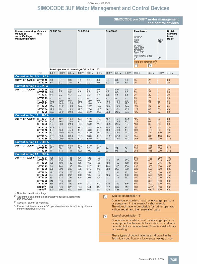
SIMOCODE 3UF Motor Management and Control Devices
7/25Siemens LV 1 T · 2009
SIMOCODE pro 3UF7 motor managementand control devices
71) Note the operational voltage.2) Assignment and short-circuit protective devices according to
IEC 60947-4-1.3) Contactor cannot be mounted.4) Ensure that the maximum AC-3 operational current is sufficiently different
from the rated fuse current.
Current measuring module or current/voltage measuring module
Contac-tors
CLASS 30 CLASS 35 CLASS 40 Fuse links1) British Standard fuses BS 88
LV HRCType3NA
Type 3ND
DIAZEDType 5SBNEOZEDType 5SE
Operational classgG aM
Type of coordination2) 1 2
Rated operational current Ie/AC-3 in A at ... V
Type 400 V 500 V 690 V 400 V 500 V 690 V 400 V 500 V 690 V 690 V 690 V 690 V 415 V
Current setting 0.3 ... 3.0 A3UF7 1.0-1AA00-0 3RT10 15 3.0 3.0 3.0 3.0 3.0 3.0 3.0 3.0 3.0 35 20 -- 20
3RT10 16 3.0 3.0 3.0 3.0 3.0 3.0 3.0 3.0 3.0 35 20 -- 20
Current setting 2.4 ... 25 A3UF7 1.1-1AA00-0 3RT10 15 7.0 5.0 4.0 7.0 5.0 4.0 7.0 5.0 4.0 35 20 -- 20
3RT10 16 9.0 6.5 5.2 9.0 6.5 5.2 8.5 6.5 5.2 35 20 -- 203RT10 17 9.0 9.0 6.3 9.0 9.0 6.3 8.5 8.5 6.3 35 20 -- 20
3RT10 23 -- -- -- -- -- -- -- -- -- 63 25 -- 253RT10 24 12.0 12.0 9.0 12.0 12.0 9.0 12.0 12.0 9.0 63 25 20 253RT10 25 14.0 14.0 13.0 13.0 13.0 13.0 12.0 12.0 12.0 63 25 20 253RT10 26 14.0 14.0 13.0 13.0 13.0 13.0 12.0 12.0 12.0 100 35 20 25
3RT10 34 19.1 19.1 19.1 17.6 17.6 17.6 16.1 16.1 16.1 125 63 50 633RT10 35 25.0 25.0 24.0 25.0 25.0 24.0 23.5 23.5 23.5 125 63 50 63
Current setting 10 ... 100 A3UF7 1.2-1AA00-0 3RT10 34 19.1 19.1 19.1 17.6 17.6 17.6 16.1 16.1 16.1 125 63 50 63
3RT10 35 26.5 26.5 24.0 25.0 25.0 24.0 23.5 23.5 23.5 125 63 50 803RT10 36 26.5 26.5 24.0 25.0 25.0 24.0 23.5 23.5 23.5 160 80 50 80
3RT10 44 41.7 41.7 41.7 38.2 38.2 38.2 34.5 34.5 34.5 200 125 63 1253RT10 45 45.0 45.0 45.0 43.0 43.0 43.0 40.0 40.0 40.0 200 160 80 1603RT10 46 50.0 50.0 50.0 47.0 47.0 47.0 44.0 44.0 44.0 200 160 100 160
3RT10 54 69.0 69.0 69.0 63.0 63.0 63.0 57.0 57.0 57.0 355 315 160 2503RT10 55 90.0 90.0 90.0 82.0 82.0 82.0 74.0 74.0 74.0 355 315 200 315
Current setting 20 ... 200 A3UF7 1.3-1.A00-0 3RT10 54 69.0 69.0 69.0 64.0 64.0 64.0 -- -- -- 355 315 160 250
3RT10 55 90 90 90 82 82 82 74 74 74 355 315 200 3153RT10 56 111 111 111 102 102 102 93 93 93 355 315 200 315
Current setting 63 ... 630 A3UF7 1.4-1BA00-0 3RT10 64 135 135 135 126 126 126 -- -- -- 500 400 250 400
3RT10 65 159 159 159 146 146 146 133 133 133 500 400 315 4003RT10 66 180 180 180 165 165 165 150 150 150 500 400 315 400
3RT10 75 240 240 240 220 220 220 200 200 200 630 500 400 4503RT10 76 300 300 300 275 275 275 250 250 250 630 500 500 500
3RT12 64 173 173 173 152 152 152 131 131 131 500 500 400 4503RT12 65 204 204 204 180 180 180 156 156 156 500 500 400 4503RT12 66 231 231 231 204 204 204 177 177 177 500 500 400 450
3RT12 75 316 316 316 -- -- -- -- -- -- 800 800 630 8003RT12 76 385 385 385 340 340 340 316 316 316 800 800 630 800
3TF683) 376 376 376 344 344 344 317 317 317 800 5004) 630 5003TF693) 500 500 500 469 469 469 438 438 438 800 6304) 630 630
1ToC
2ToC
Type of coordination "1"
Contactors or starters must not endanger persons or equipment in the event of a short-circuit. They do not have to be suitable for further operation without repair and the renewal of parts.
Type of coordination "2"
Contactors or starters must not endanger persons or equipment in the event of a short-circuit and must be suitable for continued use. There is a risk of con-tact welding.
These types of coordination are indicated in the Technical specifications by orange backgrounds.
1ToC
2ToC
LV1T_2009_Gesamtbuch_EN.book Seite 25 Donnerstag, 26. Februar 2009 2:00 14
© Siemens AG 2009

SIMOCODE 3UF Motor Management and Control Devices
SIMOCODE pro 3UF7 motor managementand control devices
7/26 Siemens LV 1 T · 2009
7
■ Dimensional drawings
Basic unit 1, SIMOCODE pro C, 3UF7 000
3UF7 100, 3UF7 101 current measuring module (straight-through transformer)
Basic unit 2, SIMOCODE pro V, 3UF7 010
3UF7 102 current measuring module(straight-through transformer)
3UF7 103 current measuring module (straight-through transformer)
1
2 1
� ��1
��
2
�
�������3
� 2
���������
� 2 � �2
�
� �� �
3 4 2
� �
� ��1
��
2
� 2
� � 2
2 1 2
�
�������35
2 2 1 3
5�
12
� �
2
��������
� �
� �
� �
� � �
5 2
35
52
2 � � �
3
� 2
��������
3
LV1T_2009_Gesamtbuch_EN.book Seite 26 Donnerstag, 26. Februar 2009 2:00 14
© Siemens AG 2009

SIMOCODE 3UF Motor Management and Control Devices
7/27Siemens LV 1 T · 2009
SIMOCODE pro 3UF7 motor managementand control devices
7
3UF7 103 current measuring module (busbar connection)
3UF7 104 current measuring module (busbar connection)
�������
� � �
5 2
3 � 35
35
52
��5
3 � 3
� � �
2
�
� � 2
23
� 22 �� �
5
2
���
��3
� � 2
1
� �
1 � 4 2
1�42
1��������
LV1T_2009_Gesamtbuch_EN.book Seite 27 Donnerstag, 26. Februar 2009 2:00 14
© Siemens AG 2009

SIMOCODE 3UF Motor Management and Control Devices
SIMOCODE pro 3UF7 motor managementand control devices
7/28 Siemens LV 1 T · 2009
7
3UF7 110, 3UF7 111 current/voltage measuring module (straight-through transformer)
3UF7 112 current/voltage measuring module (straight-through transformer)
3UF7 113 current/voltage measuring module (straight-through transformer)
2
� 2 �2
1 1
��
3
� �
����������
� �
� �
� �
2 2
5�
5 �
2 1 �
� �
��
�
���������
� �
� �
� �
� � �
5 2
35
52
2
� � �
3
� 2
����������
3
1
3
LV1T_2009_Gesamtbuch_EN.book Seite 28 Donnerstag, 26. Februar 2009 2:00 14
© Siemens AG 2009

SIMOCODE 3UF Motor Management and Control Devices
7/29Siemens LV 1 T · 2009
SIMOCODE pro 3UF7 motor managementand control devices
7
3UF7 113 current/voltage measuring module (busbar connection)
3UF7 114 current/voltage measuring module (busbar connection)
���������
� � �
5 2
3 � 35
35
52
��5
3 � 3
� � �
2
3 5
6
14967
8832125
147
122
254811
9
NS
A0_
0040
4
145
LV1T_2009_Gesamtbuch_EN.book Seite 29 Donnerstag, 26. Februar 2009 2:00 14
© Siemens AG 2009

SIMOCODE 3UF Motor Management and Control Devices
SIMOCODE pro 3UF7 motor managementand control devices
7/30 Siemens LV 1 T · 2009
7
3UF7 200 operator panel
3UF7 210 operator panel with display
3UF7 922 adapter for operator panel
3UF7 920 door adapter
3UF7 3 digital module3UF7 4 analog module3UF7 5 ground-fault module3UF7 7 temperature module3UF7 15 decoupling module
298 7
2936
NS
A0_
0038
5a89
96
NS
A0_
0046
3b
5560
2933
91,5
96
NS
A0_
0046
4
6238
100
63 51
37
�������3
� 3
�1
3
5
� � 22 �
��
1 5�
� � 4 2
� � � � � � � 1
LV1T_2009_Gesamtbuch_EN.book Seite 30 Donnerstag, 26. Februar 2009 2:00 14
© Siemens AG 2009

SIMOCODE 3UF Motor Management and Control Devices
7/31Siemens LV 1 T · 2009
SIMOCODE pro 3UF7 motor managementand control devices
7
■ Schematics
Reversing starter with SIMOCODE pro
Circuit diagrams for additional control functions can be referred to in the SIMOCODE pro system manual
■ More information
System manual
For selection of equipment and for configuration, it is recom-mended that the 3UF7 970-0AA0.-0 system manual is consulted.
InternetYou can find further information on the Internet at: http://www.siemens.com/simocode
4�
�(-
44�
(-
� �.:
� ,
� � �
�6�
4� 4 4�
��� ��
�D�
����
E5
� ��
� � �
, �
� � �
, �
� � ,�6�
�6
@�A
�#�
� �
5 < 7
#�� 9
(- .:
���� ��6��
�(-.(- E6�
�
�
�
4�
�
�.�.(-�� 9���FG��,��<
()*�+E5�
�.��� 9���FG����< �.��� 9���FG����<
�4�
��
�
�
���� ���
� ,
()*�+E5���( ��<� 9
�� �
,<+�,+��+�+��
�, �,���� ��� ����
�� � ��
�� � �� � ��6��
(�9
�C�@�A
�
�C@A
�
�5�� �5�
�;�
�-<+9-
�;�
�
@,A @�A
�5��
�
E E
@A
�C.:,
@�A
�C�.:,
(-
� �� , � � �
� �
9�� 9���� G G G G G
E5� H-�:� 54�
�� �1��,��
@�A
@�A��#����'��!�'!���'��'0 �$�@A��#����'��!�'!���'���!��'��'0 �$�@�A��4�'������@,A��4�'���'��'0 �$�@�A��4�'���'���!��'��'0 �$�
*%���!���%����
��2�'�E5�H��:�����!��$!.��$�!
�+#*9*�-�%���9.<E�$�'����!
9�����!���!�'!���
-+�@ -+�A 5� �-��)-�-�
LV1T_2009_Gesamtbuch_EN.book Seite 31 Donnerstag, 26. Februar 2009 2:00 14
© Siemens AG 2009

SIMOCODE 3UF Motor Management and Control Devices
3UF18 current transformersfor overload protection
7/32 Siemens LV 1 T · 2009
7
■ Overview
The 3UF18 current transformers are protection transformers and are used for actuating overload relays. Protection transformers are designed to ensure proportional current transfer up to a mul-
tiple of the primary rated current. The 3UF18 current transform-ers convert the maximum current of the corresponding operating range into the standard value of 1 A secondary.
■ Technical specifications
1) With or without box terminal.2) Conductor cross-sections for box terminals, see 3TF68 and
3TF69 contactors in the section "Contactors and Contactor Assemblies".3) With max. conductor cross-section, a terminal cover for maintaining the
phase spacing is required.
Climatic environmental conditions
Temperatures• Operation °C -25 ... +60 • Storage/transport °C -40 ... +85
Temperature changes• Operation °C/h Max. 10• Storage/transport °C/h Max. 20
Relative humidity % 15 ... 95 (indoor, acc. to IEC 60721-3, no condensation)
Air pressure• Operation hPa 860 ... 1060 • Storage/transport hPa 650 ... 1060
Contaminants• SO2 ppm 0.5 (relative humidity ≤ 60 %, no condensation) • H2S ppm 0.1 (relative humidity ≤ 60 %, no condensation) Mechanical environmental conditionsVibrations (acc. to IEC 60068-2-6)
HzHz
10 ... 57 (for constant amplitude 0.15 nm)57 ... 150 (for constant acceleration 2 g)
Shock (acc. to IEC 60068-2-27) 12 shocks (half-sine 15 g/11 ms)Requirements acc. to IEC and ENDegree of protection (acc. to IEC 60529) IP20
Rated insulation voltage V 690/1000 (type-dependent)
Rating of the insulation (acc. to UL/CSA)
V 600
Trip class (acc. to IEC 60947-4-1) Suitable from CLASS 5 to CLASS 30
Power loss per conducting path of the transformers
Operating range For setting ...
To the lower limit To the upper limit
A mW (mVA) mW (mVA)• 3UF18 45 12.5 ... 50 33 (38) 570 (650)• 3UF18 48 25 ... 100 110 (120) 1700 (1900)• 3UF18 50 32 ... 130 135 (150) 2400 (2700)• 3UF18 52 50 ... 200 170 (190) 2600 (2900)• 3UF18 56 100 ... 400 450 (500) 6500 (7000)• 3UF18 57 125 ... 500 850 (940) 13000 (15000)• 3UF18 68-3F 160 ... 630 900 (1000) 17000 (19000)• 3UF18 68-3G 205 ... 820 1400 (1600) 22000 (25000)
Conductor cross-sections (one or two conductors can be connected)
Current transformers
On secondary side
On primary side
3UF18 453UF18 481)
3UF18 501)
For connection data see "3RT Contactors"
3UF18 52 3UF18 56 3UF18 572)
3UF18 68-3FA002)
3UF18 68-3GA002)
• Terminal screw M 3.5 M 8 M 10 M 10 M 12• Solid mm2 2 × 1.5 ... 2.5 -- -- -- --• Stranded mm2 2 × 1.5 ... 2.5 -- -- -- --• Finely stranded without end sleeve mm2 -- -- -- -- --• Finely stranded with end sleeve mm2 2 × 1.5 -- -- -- --• Finely stranded with cable lug mm2 -- 35 ... 95 50 ... 2403) 50 ... 240 185 ... 240• Stranded with cable lug mm2 -- 50 ... 120 70 ... 2403) 70 ... 240 185 ... 240• Connecting bars mm -- 20 × 4 25 × 6.30 × 6 30 × 5 50 × 5• Tightening torque Nm 0.8 ... 1.4 10 ... 14 14 ... 24 14 ... 24 14 ... 24• Tightening torque lb 7 ... 12 89 ... 124 124 ... 210 124 ... 210 124 ... 210
LV1T_2009_Gesamtbuch_EN.book Seite 32 Donnerstag, 26. Februar 2009 2:00 14
© Siemens AG 2009

SIMOCODE 3UF Motor Management and Control Devices
7/33Siemens LV 1 T · 2009
3UF18 current transformersfor overload protection
7
Short-circuit protection with fuses for motor feeders for short-circuit currents up to 50 kA at 690 V3), 50/60 Hz
1) Note the operational voltage.2) Assignment and short-circuit protective devices according to
IEC 60947-4-1.3) Voltage tolerance +5 %.
Overload relay Contactors Rated operational current Ie AC-3 in A with 400 V and Class ...
Type of coor-dination 12)
Type of coordination 22)
5 and 10 15 20 25 30 Fuse links in A1)
LV HRC, type 3NADIAZED, type 5SB NEOZED, type 5SEgL/gG
LV HRC, type 3NADIAZED, type 5SB NEOZED, type 5SEgL/gG
LV HRC, type 3ND
aM
British Standards fuses BS 88
Operating range 0.25 ... 2.5 A3UF18 43-1BA00 3RT10 15 2.5 2.5 2.5 2.5 2.5 25 10 -- --
Operating range 1.25 ... 12.5 A3UF18 43-1AA00 3RT10 15 7 7 7 7 7 25 10 -- --
3RT10 16 9 9 9 9 9 25 10 -- --3RT10 17 12 11 10 9.5 9 25 10 -- --
3RT10 24 12 12 12 12 12 35 16 20 353RT10 25 12.5 12.5 12.5 12.5 12.5 35 16 20 35
Operating range 2.5 ... 25 A3UF18 43-2BA00 3RT10 15 7 7 7 7 7 25 10 -- --
3RT10 16 9 9 9 9 9 25 10 -- --3RT10 17 12 11 10 9.5 9 25 10 -- --
3RT10 24 12 12 12 12 12 63 25 20 353RT10 25 17 17 16 15 14 63 25 20 353RT10 26 25 18 16 15 14 63 25 35 50
3RT10 34 -- 25 22.3 20.3 19.1 63 25 -- --3RT10 35 -- -- 25 25 25 63 25 -- --
Operating range 12.5 ... 50 A3UF18 45-2CA00 3RT10 25 17 17 16 15 14 63 25 20 35
3RT10 26 25 18 16 15 14 100 35 35 50
3RT10 34 32 25.5 22.3 20.3 19.1 100 63 -- --
3RT10 35 40 33 29.4 28 26.5 100 63 -- --3RT10 36 50 38.5 32.7 29.4 26.5 100 80 -- --
3RT10 44 -- 50 49 45 41.7 100 80 -- --3RT10 45 -- -- 50 47 45 100 80 -- --3RT10 46 -- -- -- 50 50 100 80 -- --
Operating range 16 ... 65 A3UF18 47-2DA00 3RT10 34 32 25.5 22.3 20.3 19.1 125 63 -- --
3RT10 35 40 33 29.4 28 26.5 125 63 -- --3RT10 36 50 38.5 32.7 29.4 26.5 160 80 -- --
3RT10 44 65 56 49 45 41.7 160 125 -- --3RT10 45 65 61 53 47 45 160 125 -- --3RT10 46 -- 65 59 53 50 160 125 -- --
3RT10 54 65 65 65 65 65 160 125 -- --
Operating range 25 ... 100 A3UF1 848-2EA00 3RT10 44 65 65 49 45 41.7 250 125 -- --
3RT10 45 80 61 53 47 45 250 160 -- --3RT10 46 95 69 59 53 50 250 160 -- --
3RT10 54 100 93 82 75 69 250 160 125 1253RT10 55 -- 100 100 98 90 250 160 125 1253RT10 56 -- -- -- 100 100 250 160 125 125
1ToC
2ToC
LV1T_2009_Gesamtbuch_EN.book Seite 33 Donnerstag, 26. Februar 2009 2:00 14
© Siemens AG 2009

SIMOCODE 3UF Motor Management and Control Devices
3UF18 current transformersfor overload protection
7/34 Siemens LV 1 T · 2009
7
1) Note the operational voltage.2) Assignment and short-circuit protective devices according to
IEC 60947-4-1.
Overload relay Contactors Rated operational current Ie AC-3 in A with 400 V and Class ...
Type of coor-dination 12)
Type of coordination 22)
5 and 10 15 20 25 30 Fuse links in A1)
LV HRC, type 3NADIAZED, type 5SB NEOZED, type 5SEgL/gG
LV HRC, type 3NADIAZED, type 5SB NEOZED, type 5SEgL/gG
LV HRC, type 3ND
aM
British Standards fuses BS 88
Operating range 32 ... 130 A3UF18 50-3AA00 3RT10 44 65 56 49 45 41.7 250 125 -- --
3RT10 45 80 61 53 47 45 250 160 -- --3RT10 46 95 69 59 53 50 250 160 -- --
3RT10 54 115 93 82 75 69 315 224 160 1603RT10 55 130 122 107 98 90 315 224 160 1603RT10 56 -- 130 130 120 111 315 224 160 160
3RT10 64 -- -- -- 130 130 315 224 160 160Operating range 50 ... 200 A3UF18 52-3BA00 3RT10 54 115 93 82 75 69 355 224 160 200
3RT10 55 150 122 107 98 90 355 224 160 2003RT10 56 185 150 131 120 111 355 224 160 200
3RT10 64 200 182 160 146 135 355 224 160 2003RT10 65 -- 200 188 172 159 355 224 160 2003RT10 66 -- -- 200 195 180 355 224 160 200
3RT10 75 -- -- -- 200 200 355 224 160 200Operating range 63 ... 250 A3UF18 54-3CA00 3RT10 56 185 150 131 120 111 355 250 160 200
3RT10 64 225 182 160 146 135 400 250 250 3553RT10 65 250 215 188 172 159 500 400 315 3553RT10 66 -- 243 213 195 180 500 400 315 355
3RT10 75 -- 250 250 250 240 500 400 400 3553RT10 76 -- -- -- -- 250 500 400 400 355
Operating range 100 ... 400 A3UF18 56-3DA00 3RT10 65 265 215 188 172 159 500 400 315 400
3RT10 66 300 243 213 195 180 500 400 315 400
3RT10 75 400 324 284 260 240 630 500 400 4503RT10 76 -- 400 355 325 300 630 500 500 450
3TF68 -- -- 400 400 400 800 500 630 450Operating range 125 ... 500 A3UF18 57-3EA00 3RT10 66 300 243 213 195 180 500 400 315 400
3RT10 75 400 324 284 260 240 800 500 400 4503RT10 76 500 405 355 325 300 800 500 500 450
3TF68 -- 500 500 479 441 800 500 630 4503TF69 -- -- -- 500 500 800 500 630 450
Operating range 160 ... 630 A3UF18 68-3FA00 3RT10 75 400 324 284 260 240 800 500 400 450
3RT10 76 500 405 355 325 300 800 500 500 450
3TF68 630 630 536 479 441 1000 500 630 4503TF69 -- -- -- 531 500 1000 500 630 450
Operating range 200 ... 820 A3UF18 69-3GA00 3TF68 630 630 536 479 441 1000 500 630 450
3TF69 820 662 572 531 500 1000 500 630 450
1ToC
2ToC
LV1T_2009_Gesamtbuch_EN.book Seite 34 Donnerstag, 26. Februar 2009 2:00 14
© Siemens AG 2009

SIMOCODE 3UF Motor Management and Control Devices
7/35Siemens LV 1 T · 2009
3UF18 current transformersfor overload protection
7
■ Dimensional drawings
3UF18 43 current transformer
3UF18 45 current transformerfor stand-alone installation: for screw and snap-on mounting onto TH 35 standard mounting rails according to EN 60715
1) Clearance to grounded components.2) Snap-on mounting onto standard mounting rails
EN 60715-35 x 7.5 or EN 60715-35 x 15.
3UF18 47 to 3UF18 52 current transformers
3UF18 54 to 3UF18 57 current transformers
2
��
32
% �
2
� 2
��������22
1 5 �
5
3
21
5
� 4 2
2
�
52
� � �
� � � � � � � � 2 1
21
1 2 2
� 2
1� � � �
% �
% 4 2 ��
1
��
a a
b
d e f
n
q
ml
hi
j6,2
k
g
NS
A0_
0015
7c
1
Ø
1
� � � -* $�
� 2 + � � 3 � 4
� 2 + � � 3 � 3
� 2 + � � 3 * �
� 2 + � � 3 * �
6 7 � � � � �
6 7 � � � � 2
6 7 � � � � 1
� 1 4 2
� 1 4 2
3
� �
� 2
� 2
3 4 2
3 4 2
�
�
3 � 4 2
3 � 4 2
� � �
� � �
5 5
� � �
� � �
� � �
� � �
� � �
� � 4 2
� � 4 2
� 2
� �
5 �
5 �
� � �
� � �
� 1
� 1
� �
� �
5 �
5 �
� � �
� � �
� � 2
� � 2
5 2
5 2
2
2
1 �
1 �
1 3
1 3
5
5
5
5
8
8
8
8
1 4 �
1 4 �
1 4 1
5
� " & ( � ,
Additional cover, can be shortened
� � � � ! � � 5 � � ! " � � � � � � !
NSB0_01476a
14550
110
134
62
666 15
127
0,510
j i
k l
9
88
� 2 + � 3 � * �
� 2 + � 3 � * �
� 2 + � 3 � * 4
�
�
2 �
� 2
� 2
�
� �
� �
�
� 2 5
� 2 5
� 1
� , � �
11 for M10
� � � � ! � � 5 � � !
LV1T_2009_Gesamtbuch_EN.book Seite 35 Donnerstag, 26. Februar 2009 2:00 14
© Siemens AG 2009

SIMOCODE 3UF Motor Management and Control Devices
3UF18 current transformersfor overload protection
7/36 Siemens LV 1 T · 2009
7
3UF18 68-3FA00, 3UF18 68-3GA00 current transformersfor 3TF68 contactors
NSA0_00159a0,5
4015
170
230
74
230100
28
232
220
210
174
14012
7070
105
c
a
b
gfe
d
12
� 2
� 2 + � 3 � � 3 � � + 6 � �
� 2 + � 3 � � 3 � � 7 6 � �
7 9 1
7 9 1
5 �
� � �
5
� �
�
� �
2
� � 2
� 2 2
� 3 2
� 5 2
� � �
� 2 �
� * � $ � " &
14 for M 12
14 for M 12
" � � � � � � !� � � � ! � � 5 � � !
LV1T_2009_Gesamtbuch_EN.book Seite 36 Donnerstag, 26. Februar 2009 2:00 14
© Siemens AG 2009

LOGO! Logic Modules
7/37Siemens LV 1 T · 2009
General data
7
■ Overview
• The compact, user-friendly, and low-cost solution for simple control tasks
• Compact, user-friendly, can be used universally withoutaccessories
• All in one: the display and operator panel are integrated• 4-line LOGO! TD text display can be connected directly to all
LOGO! basic versions• 39 different functions can be linked at a press of a button or
with PC software; up to 200 times in total• Functions can be changed simply using buttons;
no complicated rewiring
Catalog ST 70:
Information on LOGO! can also be found in the catalog ST 70:
http://www.siemens.com/automation/salesmaterial-as/catalog/en/st70k1ad.pdf
■ Design
The LOGO! modular design is available in different versions for different supply voltages (12 V DC, 24 V DC, 24 V AC, 115/230 V DC, 115/230 V AC):• Basic versions with operator control and display panels• Low-cost pure versions without operator control and display
panels• 4-line LOGO! TD text display can be connected directly to all
LOGO! basic versions, degree of protection IP65, including connection cable
The LOGO! versions have the following distinguishing characteristics:• R: relay output• C: clock/time switch• o: without display
LOGO! is simple:• Keypad and display field in one unit; no other tools are re-
quired• Non-volatile storage of switching program and setpoints
(e. g. times) in integrated EEPROM
LOGO! is space-saving:• e. g. LOGO! 230RC: 72 x 90 x 55 mm (W x H x D)• Fitted mounting in the distribution box (same mounting dimen-
sions as the RCCB)
LOGO! offers maximum flexibility and is universal:• Expandability:
Depending on the application, additional expansion modules can be connected
LOGO! is communication-capable:• Optional communication modules support connection to
AS-Interface and instabus EIB networks
■ Function
LOGO! is simple:• 39 functions:
Integrated basic functions (e. g. AND, OR) and special func-tions (e. g. timers, counters, latching relays, PI controllers) of the electronics
• Program generation simply by combining stored functions at the press of a button or PC software
• Easy-to-use and simple duplication of the switching program with an optional program module
• LOGO! offers maximum flexibility and is universal:• Easy modification by reconnecting the functions at a press of
a button; no need for time-consuming rewiring• Optional operation from the PC:
For creating, simulating, online testing and archiving the switching program on the PC, including documentation facility
LV1T_2009_Gesamtbuch_EN.book Seite 37 Donnerstag, 26. Februar 2009 2:00 14
© Siemens AG 2009

LOGO! Logic Modules
LOGO! Modular basic versions
7/38 Siemens LV 1 T · 2009
7
■ Overview
• The space-saving basic versions• Interface for connecting expansion modules, max. 24 digital
inputs, 16 digital outputs, 8 analog inputs and 2 analog outputs can be addressed
• Interface for direct connection of the new LOGO! TD text display
■ Design
• Relay outputs with up to 10 A output current (not LOGO! 24)• Integrated display field with background illumination
(4x12 characters)• Integrated operator control panel• Integrated EEPROM for storing switching program and set-
points• Optional program module• Integrated clock with automatic summertime/wintertime
changeover (not LOGO! 24)• 8 digital inputs, 4 digital outputs• 4 inputs as analog inputs for 12/24 V DC versions
(0 ... 10 V); inputs can also be used as digital inputs• 4 inputs for counting up to 5 kHz can be used
(for DC versions only)• Interface for connecting expansion modules, max. 24 digital
inputs, 16 digital outputs, 8 analog inputs and 2 analog out-puts can be addressed
• Interface for direct connection of the new LOGO! TD text displays
■ Function
• Integrated basic and special functions: • Basic functions:
AND, OR, NOT, NAND, NOR, XOR, positive/negative edge evaluation
• Special functions: ON delay, latching ON-delay, OFF-delay, pulse relay, latching relay, counter (forwards/backwards), time switch, interval time-delay relay, operating hours counter, threshold switch, asynchronous pulse encoder, twelve-month time switch, easy-to-use switch function, random generator, staircase lighting function according to DIN 18015-2, edge-triggered interval time-delay relay, combined ON/OFF-delay, analog compara-tor, analog threshold switch, analog delta threshold switch, an-alog watchdog, analog amplifier, text and variable display, shift register, softkey function, PI controller, ramp function, an-alog multiplexer, analog arithmetic function, PWM function
• 200 function blocks can be combined• 24 flags (including start-up flag)• Integrated retentivity• Password protection
Optional function• Additional know-how protection with the optional program
module• Additional 2-year buffer for the integrated real-time clock (not
LOGO! 24) with the optional battery and memory module/battery module
• 4-line LOGO! TD text display can be connected directly to all LOGO! basic versions
LV1T_2009_Gesamtbuch_EN.book Seite 38 Donnerstag, 26. Februar 2009 2:00 14
© Siemens AG 2009

LOGO! Logic Modules
7/39Siemens LV 1 T · 2009
LOGO! Modular pure versions
7
■ Overview
• The cost-optimized basic versions• Interface for connecting expansion modules,
max. 24 digital inputs, 16 digital outputs, 8 analog inputs and 2 analog outputs can be addressed
• Interface for direct connection of the new LOGO! TD text display
■ Design
• Relay outputs with up to 10 A output current (not LOGO! 24o).
• Integrated EEPROM for storing switching program and set-points
• Optional program module• Integrated clock with automatic summertime/wintertime
changeover (not LOGO! 24o)• 8 digital inputs, 4 digital outputs• 4 inputs as analog inputs for 12/24 V DC versions
(0 ... 10 V); inputs can also be used as digital inputs• 4 inputs for counting up to 5 kHz can be used
(for DC versions only)• Interface for connecting expansion modules,
max. 24 digital inputs, 16 digital outputs, 8 analog inputs and 2 analog outputs can be addressed
• Interface for direct connection of the new LOGO! TD text displays
■ Function
• Integrated basic and special functions: • Basic functions:
AND, OR, NOT, NAND, NOR, XOR, positive/negative edge evaluation
• Special functions: ON delay, latching ON-delay, OFF-delay, pulse relay, latching relay, counter (forwards/backwards), time switch, interval time-delay relay, operating hours counter, threshold switch, asynchronous pulse encoder, twelve-month time switch, easy-to-use switch function, random generator, staircase lighting function according to DIN 18015-2, edge-triggered interval time-delay relay, combined ON/OFF-delay, analog compara-tor, analog threshold switch, analog delta threshold switch, an-alog watchdog, analog amplifier,shift register, softkey func-tion, PI controller, ramp function, analog multiplexer, analog arithmetic function, PWM function
• 200 function blocks can be combined• 24 flags (including start-up flag)• Integrated retentivity• Password protection
Optional function• Additional know-how protection with the optional program
module• Additional 2-year buffer for the integrated real-time clock with
the optional battery and memory module/battery module• 4-line LOGO! TD text display can be connected directly to all
LOGO! basic versions
LV1T_2009_Gesamtbuch_EN.book Seite 39 Donnerstag, 26. Februar 2009 2:00 14
© Siemens AG 2009

LOGO! Logic Modules
LOGO! Software
7/40 Siemens LV 1 T · 2009
7
■ Overview
• The user-friendly software for switching program generation on the PC
• Switching program generation for function diagrams (FBD) or contact diagrams (LAD)
• Additional testing, simulation, online testing and archiving of the switching programs
• Professional documentation with the help of various comment and print functions
■ Design
The connection between LOGO! and the PC is established with the help of the LOGO! PC cable (serial or USB interface)
Minimum system requirements
Windows 98 SE, NT 4.0, ME, 2000, XP or Vista• Pentium PC• 90 Mbyte free on hard disk• 64 Mbyte RAM• SVGA graphics card with minimum 800x600 resolution
(256 colors)
Mac OS X• PowerMac G3, G4, G4 Cube, iMac, PowerBook G3, G4 or
iBook
Linux (tested with Caldera OpenLinux 2.4)• Runs on all Linux releases on which Java 2 SDK Version 1.3.1
runs• Please consult your Linux release for hardware requirements
■ Function
• Control program generation with the programming languages FBD and LAD (switchable). How to place the functions on the drawing board by means of "Drag and Drop" is almost self-explanatory
• Comprehensive documentation functions: Various print options permit professional documentation
• Program simulation (offline): For preliminary testing of switching programs on the PC
• Program test (online): The current values of LOGO! are presented on screen, for FBD and LAD
• Analog modem communication for remote servicing of LOGO! with program UP/DOWN load and online test
• Comprehensive, context-sensitive online help functions
The following functions are available:• Basic functions (AND, OR, NOT, NAND, NOR, XOR, positive
edge evaluation, negative edge evaluation)• ON-delay• OFF-delay• Current impulse relay• Latching• Latching ON-delay• Operating hours counter• Interval time-delay relay/pulse output mode• Up/down counter• Threshold switch• Pulse encoder• Twelve-month time switch• Time switch• ON/OFF-delay• Random generator• Edge-triggered interval time-delay relay• Analog threshold switch• Analog comparator• Analog delta threshold switch• Analog watchdog• Analog amplifier• Staircase lighting switch• Easy-to-use switch• Message texts• Shift register• Softkey• PI controller• Ramp function• Analog multiplexer• Analog arithmetic function• PWM function
LV1T_2009_Gesamtbuch_EN.book Seite 40 Donnerstag, 26. Februar 2009 2:00 14
© Siemens AG 2009

3RP, 3RT19 Timing Relays
7/41Siemens LV 1 T · 2009
General data
7
■ Function
3RP15 and 3RP20 function table
1) Note on function with start contact: A new control signal at terminal B, after the operating time has started, resets the operating time to zero.
This does not apply to G, G! and H, H!, which are not retriggerable.
7 Function is possible
Function Function chart 3RP20 timing relay and 3RP19 01 label set
3RP15 timing relay and 3RP19 01 label set
Timing relay energized
Contact closed
Contact open
3RP
20 0
5-.A
3RP
20 2
5
3RP
15 0
5-.A
3RP
19 0
1-0A
Iden
tific
atio
n le
tter
3RP
15 1
.
3RP
15 2
5
3RP
15 2
7
3RP
15 3
.
3RP
15 4
0
3RP
15 5
5
3RP
15 7
.
1 CO contactWith ON-delay 7 7 7 A 7 7
OFF-delay with auxiliary voltage
7 7 B1)7
OFF-delay without auxiliary voltageObserve minimum ON period for correct operation. For 3RP15 40-..W31: Us 24 to 40 V AC/DC: 400 ms and Us > 40 to 240 V AC/DC: 200 ms.
7
ON-delay and OFF-delay with auxiliary voltage (t = ton = toff)
7 7 C1)
Flashing, starting with interval (pulse/interval 1:1)
7 7 D
Clock-pulse, starting with interval (dead time, pulse time, and time setting ranges each separately adjustable)
7
Passing make contact 7 7 E
Passing break contact with auxiliary voltage
7 7 F1)
Pulse-forming with auxiliary voltage (pulse generation at the output does not depend on duration of energizing)
7 7 G1)
Additive ON-delay with auxiliary voltage
7 7 H1)
1 NO contact (semiconductor)ON-delay The two-wire timing relay is connected in series with the load. Timing begins after appli-cation of the exciting voltage. The semicon-ductor output then becomes conducting, and the load is under power.
7
�
��������
��
��
��
A1/A2
15/1815/16
t
35 ms
NS
B00
859B1/A2
>
15/16
A1/A2
200 ms
t
15/18
NS
B0_
0086
0a
tt
NS
B00
861
15/16
A1/A2
15/18
B1/A2
NS
B00
862
t t
15/16
A1/A2
15/18
NS
B00
863
15/16
A1/A2
15/18
Interval Pulse period
NS
B00
864
t
A1/A2
15/1815/16
t
NS
B00
865
35 ms>A1/A2
15/1815/16
B1/A2
t
NS
B00
867
>A1/A2
15/1815/16
B1/A2
35 ms
t
NS
B00
868
t1 t2t3
A1/A2
15/1815/16
B1/A2
�
��
���������
LV1T_2009_Gesamtbuch_EN.book Seite 41 Donnerstag, 26. Februar 2009 2:00 14
© Siemens AG 2009
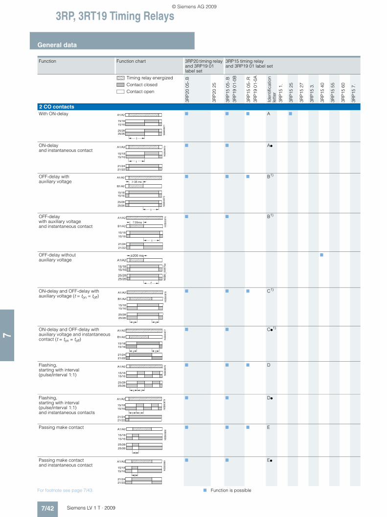
3RP, 3RT19 Timing Relays
General data
7/42 Siemens LV 1 T · 2009
7
For footnote see page 7/43. 7 Function is possible
Function Function chart 3RP20 timing relay and 3RP19 01 label set
3RP15 timing relay and 3RP19 01 label set
Timing relay energized
Contact closed
Contact open
3RP
20 0
5-.B
3RP
20 2
5
3RP
15 0
5-.B
3RP
19 0
1-0B
3RP
15 0
5-.R
3RP
19 0
1-0A
Iden
tific
atio
n le
tter
3RP
15 1
.
3RP
15 2
5
3RP
15 2
7
3RP
15 3
.
3RP
15 4
0
3RP
15 5
5
3RP
15 6
0
3RP
15 7
.
2 CO contactsWith ON-delay 7 7 7 A 7
ON-delay and instantaneous contact
7 7 A!
OFF-delay with auxiliary voltage
7 7 7 B1)
OFF-delay with auxiliary voltage and instantaneous contact
7 7 B1)
OFF-delay without auxiliary voltage
7
ON-delay and OFF-delay with auxiliary voltage (t = ton = toff)
7 7 7 C1)
ON-delay and OFF-delay with auxiliary voltage and instantaneous contact (t = ton = toff)
7 7 C!1)
Flashing, starting with interval (pulse/interval 1:1)
7 7 7 D
Flashing, starting with interval (pulse/interval 1:1) and instantaneous contacts
7 7 D!
Passing make contact 7 7 7 E
Passing make contact and instantaneous contact
7 7 E!
t
NS
B00
871
A1/A2
15/1815/16
25/2825/26
15/1815/16
t
A1/A2
NS
B00
872
21/2421/22
t
NS
B00
873
>A1/A2
15/1815/16
B1/A2
25/2825/26
35 ms
��
��
�
����
�
��
��������
��
�
15/16
A1/A2200 ms
t
15/18
25/2825/26 N
SB
0_00
875a
15/1815/16
t
25/2825/26
A1/A2
B1/A2
t
NS
B00
876
15/1815/16
t21/2421/22
A1/A2
B1/A2
t
NS
B00
877
15/1815/16
t
A1/A2
25/2825/26
t
NS
B00
878
15/1815/16
21/2421/22
NS
B00
879A1/A2
t t
15/1815/16
t
A1/A2
25/2825/26
NS
B00
880
15/1815/16
21/2421/22
NS
B00
881A1/A2
t
LV1T_2009_Gesamtbuch_EN.book Seite 42 Donnerstag, 26. Februar 2009 2:00 14
© Siemens AG 2009

3RP, 3RT19 Timing Relays
7/43Siemens LV 1 T · 2009
General data
7
1) Note on function with start contact: A new control signal at terminal B, after the operating time has started, resets the operating time to zero. This does not apply to G, G! and H, H!, which are not retriggerable.
2) For function diagrams showing the various possibilities of operation of the 3RP15 60-1S.30, see page 7/45.
7 Function is possible
Function Function chart 3RP20 timing relay and3RP19 01label set
3RP15 timing relay and 3RP19 01 label set
Timing relay energized
Contact closed
Contact open
3RP
20 0
5-.B
3RP
20 2
5
3RP
15 0
5-.B
3RP
19 0
1-0B
3RP
15 0
5-.R
3RP
19 0
1-0A
Iden
tific
atio
n le
tter
3RP
15 1
.
3RP
15 2
5
3RP
15 2
7
3RP
15 3
.
3RP
15 4
0
3RP
15 5
5
3RP
15 6
0
3RP
15 7
.
2 CO contactsPassing break contact with auxiliary voltage
7 7 7 F1)
Passing break contact with auxiliary voltage and instantaneous contact
7 7 F!1)
Pulse-forming with auxiliary voltage (pulse generation at the output does not depend on duration of energizing)
7 7 7 G1)
Pulse-forming with auxiliary voltage and instantaneous contact) (pulse generation at the output does not depend on duration of energizing)
7 7 G!1)
Additive ON-delay with auxiliary voltage
7 H1)
Additive ON-delay with auxiliary voltage and instantaneous contact
7 7 H!1)
Wye-delta function 7 7 *Δ
2 NO contactsWye-delta function *Δ 7
3 NO contactsWye-delta function with overtravel function2)
(idling)
7
15/1815/16
t
25/28
35ms
NS
B00
882
�
25/26
B1/A2
A1/A2
15/1815/16
t
35ms
21/2421/22
NS
B00
883A1/A2
B1/A2
>
15/1815/16
t
25/2825/26
A1/A2
B1/A2
35ms
NS
B00
884
�
15/1815/16
21/2421/22
A1/A2
B1/A2
t
NS
B00
885
35ms>
����
� � � �
��
��
��
������
�
�
� ��
�����
���
�
� � � � � � � �
� � � � �� � � � �
� � � � �
� � � � �
��� �� �
�
t
A1/A2
50ms
17/18
27/28
NS
B00
888
t 50 ms
NS
B00
889A1/A2
17/1817/28
��
����
��
��
��
������
�
� �
���
������
LV1T_2009_Gesamtbuch_EN.book Seite 43 Donnerstag, 26. Februar 2009 2:00 14
© Siemens AG 2009

3RP, 3RT19 Timing Relays
General data
7/44 Siemens LV 1 T · 2009
7
Function table 3RT19 16, 3RT19 26
7 Function is possible
Function Function chart 3RT19 16 timing relays 3RT19 26 timing relays
Timing relay energized
Contact closed
Contact open
3RT1
9 16
-2C
3RT1
9 16
-2D
3RP
19 1
6-2E
3RT1
9 16
-2F
3RT1
9 16
-2G
3RT1
9 16
-2L
3RT1
9 26
-2C
3RT1
9 26
-2D
3RT1
9 26
-2E
3RT1
9 16
-2F
3RT1
9 26
-2G
1 CO contactOFF-delay with auxiliary voltage
7
1 NO contact + 1 NC contactON-delay (varistor integrated)
7
With ON-delay 7
OFF-delay without auxiliary voltage (varistor integrated)
7
OFF-delay without auxiliary voltage
7
2 NO contactsWye-delta function (varistor integrated) 1 NO delayed, 1 NO instantaneous, dead time 50 ms
7
Wye-delta function 1 NO delayed, 1 NO instantaneous, dead time 50 ms
7
1 NO contact (semiconductor)ON-delay Two-wire version (varistor integrated)
7 7
OFF-delay with auxiliary voltage (varistor integrated)
7 7
A1/A2
15/1815/16
t
35 ms
NS
B00
859B1/A2
>
t
NS
B00
933
A1/A2
27/28
35/36
NS
B00
936
A1/A2
-7/-8
-5/-6
t
t
NS
B00
934
A1/A2
27/28
35/36
200 ms>
t
NS
B00
937
-7/-8
-5/-6
200 ms>
A1/A2
t
NS
B00
935
A1/A2
Y 27/28
� � 37/38
50 ms
t
NS
B00
938
A1/A2
Y -7/-8
� � -7/-850 ms
NS
B00
939a
A1/A2
A1/A2t
Timing relay
Contactor
NS
B00
940a
A1/A2
A1/A2
B1/A2
35 ms>
t
Timing relay
Contactor
LV1T_2009_Gesamtbuch_EN.book Seite 44 Donnerstag, 26. Februar 2009 2:00 14
© Siemens AG 2009

3RP, 3RT19 Timing Relays
7/45Siemens LV 1 T · 2009
General data
7
3RP15 function table
Possibilities of operation of the 3RP15 60-1S.30 timing relay
Timing relay energized
Contact closed
Contact open
tY = Star time 1 ... 20 s
tIdling = Idling time (overtravel time) 30 ... 600 s
Operation 1 Operation 1:Start contact B./A2 is open when supply voltage A./A2 is applied.
The supply voltage is applied to A./A2 and there is no control signal on B./A2. This starts the *Δ timing. The idling time (coasting time) is started by applying a control signal to B./A2. When the set time tIdling (30 ... 600 s) has elapsed, the output relays (17/16 and 17/28) are reset. If the control signal on B./A2 is switched off (minimum OFF period 270 ms), a new timing is started.
Comments:
Observe response time (dead time) of 400 ms on energizing supply voltage until contacts 17/18 and 17/16 close.
Operation 2:Start contact B./A2 is closed when supply voltage A./A2 is applied.
If the control signal B./A2 is already present when the supply voltage A./A2 is applied, no timing is started. The timing is only started when the control signal B./A2 is switched off.
Operation 3:Start contact B./A2 closes while star time is running.
If the control signal B./A2 is applied again during the star time, the idling time starts and the timing is terminated normally.
Operation 4:Start contact B./A2 opens while delta time is running and is applied again.
If the control signal on B./A2 is applied and switched off again during the delta time, although the idling time has not yet elapsed, the idling time (coasting time) is reset to zero. If the control signal is re-applied to B./A2, the idling time is restarted.
Application example based on standard operation (operation 1): For example, use of 3RP15 60 for compressor control
Frequent starting of compressors strains the network, the machine, and the increased costs for the operator. The new timing relay prevents fre-quent starting at times when there is high demand for compressed air. A special control circuit prevents the compressor from being switched off immediately when the required air pressure in the tank has been reached. Instead, the valve in the intake tube is closed and the com-pressor runs in "Idling" mode for a specific time which can be set from 30 ... 600 s.
If the pressure falls within this time, the motor does not have to be restarted again, but can return to nominal load operation from no-load operation.
If the pressure does not fall within this idling time, the motor is switched off.
The pressure switch controls the timing via B./A2.
The supply voltage is applied to A./A2 and the start contact B./A2 is open, i.e. there is no control signal on B./A2 when the supply voltage is applied. The pressure switch signals "too little pressure in system" and starts the timing by way of terminal B./A2. The compressor is started, enters *Δ operation, and fills the pressure tank.
When the pressure switch signals "sufficient pressure", the control signal B./A2 is applied, the idling time (overtravel time) is started, and the compressor enters no-load operation for the set period of time from 30 ... 600 s. The compressor is then switched off. The compressor is only restarted if the pressure switch responds again (low pressure).
Operation 2
Operation 3
Operation 4
Note:
The following applies to all operations: The pressure switch controls the timing via B./A2.
NS
B0_
0089
1a
A./A2
B./A2
17/18 Y
17/28
17/16
Y Idlingtt 50ms Yt Idlingt
300 ms50ms
A./A2
B./A2
17/18 Y
17/28
17/16
Y
NS
B0_
0089
2a
t Idlingt 50ms
A./A2
B./A2
17/18 Y
17/28
17/16
Y
NS
B0_
0089
3a
50ms
t Idling
t
NS
B0_
0089
4b
A./A2
B./A2
17/18 Y
17/28
17/16
Y Idlingt<t Idlingt< Idlingt50ms
LV1T_2009_Gesamtbuch_EN.book Seite 45 Donnerstag, 26. Februar 2009 2:00 14
© Siemens AG 2009

3RP, 3RT19 Timing Relays
3RP15 timing relays in industrial enclosure, 22.5 mm
7/46 Siemens LV 1 T · 2009
7
■ Overview
Standards
The timing relays comply with: • EN 60947-5-1 (VDE 0660 Part 200)
"Low-voltage switchgear and controlgear – Electromechanical control circuit devices"
• EN 61812-1 (VDE 0435 Part 2021) "Specified time relays for industrial use"
• EN 60721-3-3 "Environmental conditions"• EN 61000-6-2 and EN 61000-6-4
"Electromagnetic compatibility"
Accessories
Push-in lugs for screw fixing
Sealable cover
Label set for marking the multifunction relay
■ Function
• Changes to the time setting ranges and the functions must be carried out in the de-energized state.
• Start input B1 or B3 must only be triggered when the control supply voltage is applied.
• The same potential must be applied to A1 and B1 or A3 and B3. With two-voltage version, only one voltage range must be connected.
• The activation of loads parallel to the start input is not permis-sible when using AC control supply voltage (see diagrams).
• Surge suppression is integrated in the timing relay. This pre-vents the generation of voltage peaks on the control supply voltage when the relay is switched on and off. No additional damping measures are necessary.
• 3RP15 05-.R must not be operated next to heat sources > 60 °C.
• For 3RP15 40-..W31: For correct operation, observe minimum ON period at 24 to 40 V AC/DC: 400 ms and at 40 to 240 V AC/DC: 200 ms.The timing relay has only one LED which indicates that the control supply voltage is connected. The switch position of the relay is not indicated.Setting of output contacts in as-supplied state not defined (bistable relay). Application of the control supply voltage once results in contact changeover to the correct setting.
Timing relay with multifunction
The functions can be adjusted by means of rotary switches. Insert labels can be used to adjust different functions of the 3RP15 05 timing relay clearly and unmistakably. The corresponding labels can be ordered as an accessory. The same potential must be applied to terminals A. and B.
Parallel load on start input
NSB0_01423b
LED for indicating"Timing relay on voltage"
LED for indicating"Relay switched"
Time setting range selector switch
Function switch
Device labeling plate
Operating timeadjustment
Inspection windowfor set time range
Inspection windowfor set function
K2A1
A2N
NSB0_00895a
L1
S1
K1B1
K2A1
A2N
NSB0_00896a
L1
S1 S1
K1B1
LV1T_2009_Gesamtbuch_EN.book Seite 46 Donnerstag, 26. Februar 2009 2:00 14
© Siemens AG 2009
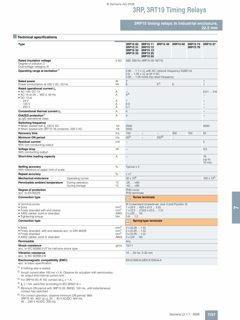
3RP, 3RT19 Timing Relays
7/47Siemens LV 1 T · 2009
3RP15 timing relays in industrial enclosure,22.5 mm
7
■ Technical specifications
1) If nothing else is stated.2) Inrush current after 100 ms <1 A. Observe for actuation with semiconduc-
tor output and internal current limit.3) For 3RP15 05-.R: NC contact -> Ie = 1 A.4) Ik ≥ 1 kA, weld-free according to IEC 60947-5-1.5) Minimum ON period with 3RP15 05-.BW30, 150 ms, until instantaneous
contact has switched.6) For correct operation, observe minimum ON period. With
3RP15 40-..W31 at Us 24 ... 40 V AC/DC: 400 ms, 40 ... 240 V AC/DC: 200 ms.
Type 3RP15 053RP15 313RP15 323RP15 33
3RP15 113RP15 123RP15 133RP15 253RP15 55
3RP15 40 3RP15 60 3RP15 743RP15 76
3RP15 27
Rated insulation voltage Degree of pollution 3Overvoltage category III
V AC 300; 500 for 3RP15 05-1BT10
Operating range at excitation1) 0.85 ... 1.1 x Us with AC network frequency 50/60 Hz0.8 ... 1.25 x Us at 24 V DC 0.95 ... 1.05 times the rated frequency
Rated power W 2 1Power consumption at 230 V AC, 50 Hz VA 6 22) 6 1
Rated operational current Ie • AC-140, DC-13 A -- 0.01 … 0.6• AC-15 at 24 ... 400 V, 50 Hz A 33) --• DC-13 at
- 24 V A 1 --- 125 V A 0.2 --- 250 V A 0.1 --
Conventional thermal current Ith A 5 --
DIAZED protection4) gL/gG operational class
A 4 --
Switching frequency • When loaded with Ie 230 V AC 1/h 2500 5000• When loaded with 3RT10 16 contactor, 230 V AC 1/h 5000
Recovery time ms 150 -- -- 300 150 50
Minimum ON period ms 355) -- 2006) --
Residual current With non-conducting output
mA -- 5
Voltage drop With conducting output
VA -- 3.5
Short-time loading capacity A -- 10 (up to 10 ms)
Setting accuracy With reference to upper limit of scale
% Typical ± 5
Repeat accuracy % ≤ ±1
Mechanical endurance Operating cycles 30 x 106 100 x 106
Permissible ambient temperature During operation °C -25 … +60During storage °C -40 … +85
Degree of protection acc. to EN 60529
IP40 cover, IP20 terminals
Connection type Screw terminals
• Terminal screw M 3 (standard screwdriver, size 2 and Pozidriv 2)• Solid mm2 1 x (0.5 ... 4)/2 x (0.5 ... 2.5)• Finely stranded with end sleeve mm2 1 x (0.5 ... 2.5)/2 x (0.5 ... 1.5)• AWG cables, solid or stranded AWG 2 x (20 ... 14)• Tightening torque Nm 0.8 … 1.2
Connection type Spring-type terminals
• Solid mm2 2 x (0.25 ... 1.5)• Finely stranded, with end sleeves acc. to DIN 46228 mm2 2 x (0.25 ... 1.5)• Finely stranded mm2 2 x (0.25 ... 1.5)• AWG cables, solid or stranded AWG 2 x (24 ... 16)
Permissible Any
Shock resistance acc. to IEC 60068-2-27 for half-sine shock type
g/ms 15/11
Vibration resistance acc. to IEC 60068-2-6
10 ... 55 Hz: 0.35 mm
Electromagnetic compatibility (EMC) acc. to basic specification
EN 61000-6-2/EN 61000-6-4
LV1T_2009_Gesamtbuch_EN.book Seite 47 Donnerstag, 26. Februar 2009 2:00 14
© Siemens AG 2009

3RP, 3RT19 Timing Relays
3RP15 timing relays in industrial enclosure, 22.5 mm
7/48 Siemens LV 1 T · 2009
7
■ Dimensional drawings
■ Schematics
3RP15 internal circuit diagrams (terminal designation to DIN 46199, Part 5)
NSB0_01698a
A C74
86536
62 90
1522,5
62 110
15
1)
22,5
82
3RP15 053RP15 25-.B3RP15 33RP15 40-.B3RP15 60
3RP15 13RP15 25-.A3RP15 273RP15 40-A3RP15 553RP15 7
A C
83 102
84 103
1) For standard mounting rail according to EN 60715.
Screw-type terminal
Spring-loaded terminal
Removable terminal
Type
3RP15 05-.A3RP15 1.3RP15 25-.A
3RP15 05-.A3RP15 3.-.A
3RP15 05-.A 3RP15 05-.A
With ON-delay OFF-delay with auxiliary voltage
ON-delay and OFF-delay with auxiliary voltage
Flashing
3RP15 05-.A 3RP15 05-.A 3RP15 05-.A 3RP15 05-.A
Passing make contact Passing break contact with auxiliary voltage
Pulse-forming with auxiliary voltage
Additive ON-delay with auxiliary voltage
�� �
� � ��������
�
�
���� ��
���� ���� �� ���
��
������
���� ��
���� ���� �� ���
� �
� ��
��� ��
��������
���� ��
���� ���� �� ���
� �
� ��
��� �� �� �
� � ��
������
�
�
���� ��
���� ���� �� ���
)
A3 15
A2 18 NS
B00
901
16
A1
AC/DC24V
AC100/127VAC200/240V
��
�����
���� ��
���� ���� �� ���
�
�
��� �� �
�� ��������
���� ��
���� ���� �� ���
�
�
��� �� �
�� ��
������
���� �,
���� �,�� �� ��,
� �
� ��
��� ��
�
LV1T_2009_Gesamtbuch_EN.book Seite 48 Donnerstag, 26. Februar 2009 2:00 14
© Siemens AG 2009

3RP, 3RT19 Timing Relays
7/49Siemens LV 1 T · 2009
3RP15 timing relays in industrial enclosure,22.5 mm
7
3RP15 27
U = 24 ... 66 V AC/DC
90 ... 240 V AC/DC
3RP15 40-.A 3RP15 55 3RP15 05-.AW30
ON-delay, two-wire version
OFF-delay without auxiliary voltage
Clock-pulse relay Multifunction relay (same functions as 3RP15 05-1A)
3RP15 05-.B, 3RP15 25-1B 3RP15 05-.B 3RP15 05-.B 3RP15 05-.B
ON-delay, 3RP15 25-1B also for 42 ... 48/60 V AC/DC (see page 7/50 3RP15 25-1BR30)
OFF-delay with auxiliary voltage ON-delay and OFF-delay with auxiliary voltage
Flashing
3RP15 05-.B 3RP15 05-.B 3RP15 05-.B 3RP15 05-.B
Passing make contact Passing break contact with auxiliary voltage
Pulse-forming with auxiliary voltage Additive ON-delay with auxiliary voltage and instantaneous contact
3RP15 05-.B 3RP15 05-.B 3RP15 05-.B 3RP15 05-.B
ON-delay and instantaneous contact
OFF-delay with auxiliary voltage and instantaneous contact
ON-delay and OFF-delay with aux-iliary voltage and instantaneous contact
Flashing and instantaneous contact
3RP15 05-.B 3RP15 05-.B 3RP15 05-.B 3RP15 05-.B
Passing make contact and instantaneous contact
Passing break contact with auxil-iary voltage and instantaneous contact
Pulse-forming with auxiliary voltage and instantaneous contact
Wye-delta function
�-
� ��
������
�
����### �(��,����#��( ��,
.���
15
A2 18 NS
B00
906a
16
A1
AC/DC100...127VAC/DC200...240VAC/DC24...240V
AC/DC24V
�
� � ��
������
�
�
���� ���� �� ���
)
�������
��
���� ������� �000���
� �
� ��
�
��2� �000 ��,
��
������
�� �
� ��
�
���� ��
���� ���� �� ���
�
� ��
������
� ��
�����
���� ��
���� ���� �� ���
� �
� �
��� ��
�
�
� � ��
����
���� ��
���� ���� �� ���
� �
� �
��� ��
�
�
� �
�� �
� ��
�
��2� �,
���� �,�� �� ��,
�
� ��
����
�
))
�� �
� � ��
�����
�
�
���� ��
���� ���� �� ���
�
� � ��
�����
���� �,
���� �,�� �� ��,
�
�
��� �� �
��
�
� � ��
�����
���� �,
���� �,�� �� ��,
�
�
��� �� �
��
�
� � ��
�����
��2� �,
���� �,�� �� ��,
� �
� ��
��� ��
�
�
�� �
� ��
�
��2� �,
���� �,�� �� ��,
� �������
��
�����
���� ��
���� ���� �� ���
� �
� �
��� ��
�
� ��
�����
���� ��
���� ���� �� ���
� �
� �
��� ��
�
�
�� �
� ��
�
���� ��
���� ���� �� ���
� ��
���� �
)
�� �
� � ��
����
�
�
���� ��
���� ���� �� ���
� ��
����
��2� �,
���� �,�� �� ��,
�
�
��� �� �
��
� ������ �
���� ��
���� ���� �� ���
�
�
��� �� �
��
�
��
<�� ��
���� �
��
��2� �,
���� �,�� �� ��,
; �
�
LV1T_2009_Gesamtbuch_EN.book Seite 49 Donnerstag, 26. Februar 2009 2:00 14
© Siemens AG 2009

3RP, 3RT19 Timing Relays
3RP15 timing relays in industrial enclosure, 22.5 mm
7/50 Siemens LV 1 T · 2009
7
Position of the terminals
Note: All the diagrams show the view onto the terminals.1) Depending on the version.
3RP15 05-.BW30/-1BT20/-.RW30 3RP15 25-. BR30 3RP15 25-. BW30 3RP15 40-.B
Multifunction relay (for functions see function table)
With ON-delay With ON-delay OFF-delay without auxiliary voltage
3RP15 60-. S 3RP15 7.-.M20 3RP15 74, 3RP15 76
Wye-delta timing relay with overtravel function (idling)
Wye-delta timing relay Wye-delta timing relay
���������
� � � � � � � �
� �
� �
� �
� �
� �
� � � � � � � � � � � �
� � � �
� � � � � � � � �
� � � � � � �
�� ��
�� ����
��
���� ���
�����
��
�� ��
��
��
��
��
��
����
���� ����
��
�� ��
��
��
���
��
��
��
A1 15
A2 18 NS
B00
926a
16
25
2826
AC/DC100...127VAC/DC200...240V
AC/DC24V
AC/DC24...240V
��
��
��
���
�!
�� "�� �� ��
������!���������
�� �� �� ��
�����
� �
� � �� � ����� ��
� �� �
� � � � � � � � � �
� � � � � � � � � �
� � �
��
����� ����� ��
��
��������
��������������������
���
3RP15 05-.A
.
3RP15 05-.AA40 3RP15 05-.AW 3RP15 05-.BP/-.BQ 3RP15 05-.BW 3RP15 05-1BT
A1 B1 15
A3 B3
16 18 A2NSB00996
for 1changeovercontact
A1 B1 15
16 18 A2NSB0_01605
A1
for 2changeover contact
�� � �
�! �� ��������
for 1changeovercontact
�� ��
�� ��
�! �� ���������
� ���
���� ���
����!
�����
for 2changeovercontacts
�� ��
�! �� ���������
� ���
���� ���
����!
�����
for 2changeovercontacts
�� ��
�! �� ���������
� ���
���� ���
����!
�����
for 2changeovercontacts
3RP15 05-.RW 3RP15 1. 3RP15 25-1A. or -1B. 1) 3RP15 27 3RP15 3.
3RP15 40 3RP15 55 3RP15 60 3RP15 7.
�� �� �
�! �� ���������
�
�! ��
for 2changeovercontacts
�� �� �
�! �� ���������
for 1changeovercontact
�� �
�! �� ��
�
�! ��
�� �� �
�! �� ���������
��
for 1changeover
for 2changeover
contact contacts
��
���������
for 1 NO contact
A1 B1 15
A3 B3
16 18 A2NSB00996
for 1changeovercontact
A1 15
16 18 A2
25
26 28
A1 15
16 18 A2NSB0_01004a
A1
A2
for 1changeovercontact
for 2changeovercontacts
�� �� �
�! �� ���������
for 1changeovercontact
�� ��
�� �� ��
�!
��
������
�� ��
for 1 NOcontact
�� �� ��
�� �� �������!
for 1 NOcontact
LV1T_2009_Gesamtbuch_EN.book Seite 50 Donnerstag, 26. Februar 2009 2:00 14
© Siemens AG 2009

3RP, 3RT19 Timing Relays
7/51Siemens LV 1 T · 2009
3RP15 timing relays in industrial enclosure,22.5 mm
7
3RP15 circuit diagrams
Note:
The contact element 17/18 is only closed in the wye stage; the contact element is open in the delta stage as well as in the de-energized state.
Control circuits (example circuits) with 3RP15 74 and 3RP15 76 wye-delta timing relays
Control circuit (example circuit) with 3RP15 60 wye-delta timing relays
For momentary-contact operation For maintained-contact operation
Size S00 to S3 Size S00 to S3
"�
������!
�#$%%&
$�#$'&
(�
�
��% �)*%#��%%+++�&
�� �� ��
�� �� �!(� (�
(� (��� ��
�� ��
(� (� (��� �� ��
�� �� ��
�� ��
��
��
�� ����
Legend:S0 Button "OFF"S1 Button "ON"S Maintained-contact buttonK1 Line contactorK2 Star contactorK3 Delta contactorK4 Timer or timing relayF0 FuseF1 Overload relayP1Pressure switch
"�
(�(�
����� ��
��
�
�#$%%&
$�#$'&
��
��
��
(�
(�
(�
�
�
"��!
��% �)�%#��&%%+++�
��
��(�
�� ��
(�
��
(�
��
��
(� (���
��
� �
� �
� �� �
� � � � � � � �
� �
� � � � � �
� � � � �
�
� �
� �
� �
�
� �
� � � � � � � � � � � � � � � � � �
�
� �
� �
� � �
� �
�
�
� �
� �
� � � �
�
�
� �
� �
�
�
�
LV1T_2009_Gesamtbuch_EN.book Seite 51 Donnerstag, 26. Februar 2009 2:00 14
© Siemens AG 2009

3RP, 3RT19 Timing Relays
3RP20 timing relays, 45 mm
7/52 Siemens LV 1 T · 2009
7
■ Overview
Standards
The timing relays comply with: • EN 60947-5-1 (VDE 0660 Part 200)
"Low-voltage switchgear and controlgear – Electromechanical control circuit devices"
• EN 61812-1 (VDE 0435 Part 2021) "Specified time relays for industrial use"
• EN 60721-3-3 "Environmental conditions"• EN 61000-6-2 and EN 61000-6-4
"Electromagnetic compatibility"• EN 61140 "Protective separation"
Accessories
Label set for marking the multifunction relay
■ Function
• Changes to the time setting ranges and the functions must be carried out in the de-energized state.
• Start input B1 or B3 must only be triggered when the control supply voltage is applied.
• The same potential must be applied to A1 and B1 or A3 and B3. With two-voltage version, only one voltage range must be connected.
• The activation of loads parallel to the start input is not permis-sible when using AC control supply (see diagrams).
• Surge suppression is integrated in the timing relay. This pre-vents the generation of voltage peaks on the control supply voltage when the relay is switched on and off. No additional damping measures are necessary.
Timing relay with multifunction
The functions can be adjusted by means of rotary switches. In-sert labels can be used to adjust different functions of the 3RP20 05 timing relay clearly and unmistakably. The corresponding labels can be ordered as an accessory. The same potential must be applied to terminals A. and B.
3RP20 05 with one changeover contact
Corresponds to the functions of 3RP15 05-.A.
3RP20 05 with two changeover contacts
Corresponds to the functions of 3RP15 05-.B.
Parallel load on start input
NSB0_01424b
LED for indicating"Timing relay excited"(left)
LED for indicating"Relay switched"(right)
Time settingrange selectorswitch
Device labelingplate
Functionswitch
Time settingrange adjuster,analog
K2A1
A2N
NSB0_00895a
L1
S1
K1B1
K2A1
A2N
NSB0_00896a
L1
S1 S1
K1B1
LV1T_2009_Gesamtbuch_EN.book Seite 52 Donnerstag, 26. Februar 2009 2:00 14
© Siemens AG 2009

3RP, 3RT19 Timing Relays
7/53Siemens LV 1 T · 2009
3RP20 timing relays, 45 mm
7
■ Technical specifications
1) If nothing else is stated.2) Ik ≥ 1 kA, weld-free according to IEC 60947-5-1.3) If two different conductor cross-sections are connected to one clamping
point, both cross-sections must lie in the range specified. If identical cross-sections are used, this restriction does not apply.
Type 3RP20 053RP20 25
Rated insulation voltage Degree of pollution 3 Overvoltage category III
V AC 300
Operating range at excitation1) 0.85 ... 1.1 x Us at AC; 0.8 ... 1.25 x Us at DC; 0.95 ... 1.05 times rated frequency
Rated power W 1Power consumption at 230 V AC, 50 Hz VA 4
Rated operational current Ie • AC-15, at 24 ... 400 V, 50 Hz A 3• DC-13 at
- 24 V A 1- 125 V A 0.2- 250 V A 0.1
Conventional thermal current Ith A 5
DIAZED protection2) gL/gG operational class
A 4
Switching frequency • When loaded with Ie 230 V AC 1/h 2500• When loaded with 3RT10 16 contactor, 230 V AC 1/h 5000
Recovery time ms 150
Minimum ON period ms 35
Setting accuracy With reference to upper limit of scale
% Typical ±5
Repeat accuracy % ≤ ±1
Mechanical endurance Operating cycles 30 x 106
Permissible ambient temperature During operation °C -25 … +60During storage °C -40 … +85
Degree of protection acc. to EN 60529
IP40 cover, IP20 terminals
Connection type Screw terminals
• Terminal screw M 3 (standard screwdriver, size 2 and Pozidriv 2)• Solid mm2 1 x (0.5 ... 4)/2 x (0.5 ... 2.5)3)
• Finely stranded with end sleeve mm2 1 x (0.5 ... 2.5)/2 x (0.5 ... 1.5)3)
• AWG cables, solid or stranded AWG 2 x (20 ... 14)3)
• Tightening torque Nm 0.8 … 1.2
Connection type Spring-type terminals
• Solid mm2 2 x (0.25 ... 1.5)• Finely stranded, with end sleeves acc. to DIN 46228 mm2 2 x (0.25 ... 1.5)• Finely stranded mm2 2 x (0.25 ... 1.5)• AWG cables, solid or stranded AWG 2 x (24 ... 16)
Permissible Any
Shock resistance acc. to IEC 60068 for half-sine shock type
g/ms 15/11
Vibration resistance acc. to IEC 60068-2-6
10 ... 55 Hz: 0.35 mm
Electromagnetic compatibility (EMC) acc. to basic specification
EN 61000-6-2/EN 61000-6-4
LV1T_2009_Gesamtbuch_EN.book Seite 53 Donnerstag, 26. Februar 2009 2:00 14
© Siemens AG 2009

3RP, 3RT19 Timing Relays
3RP20 timing relays, 45 mm
7/54 Siemens LV 1 T · 2009
7
■ Dimensional drawings
■ Schematics
3RP20 internal circuit diagrams (terminal designation to DIN 46199, Part 5)
Position of the terminals
Note:
All the diagrams show the view onto the terminals.
� �
� � � � � � �
�� ��
� �����
����
�
� �
�
��
3RP20 053RP20 25
3RP20 05 3RP20 05 3RP20 05
With ON-delay OFF-delay with auxiliary voltage
ON-delay and OFF-delay with auxiliary voltage
Flashing
3RP20 05 3RP20 05 3RP20 05
Passing make contact Passing break contact with auxiliary voltage
Pulse-forming with auxiliary voltage
�� ��
�� �� �
�
��
�
��
��
��������
�������� �����������
�
��
��
��
��������
�������� �����������
�� ��
�� ����
���� ��
�
�
��
��
��������
�������� �����������
�� ��
�� ����
��� � �� ��
�� �� �
��
��
��
��
��
��������
�������� �����������
+
A3 15
A2 18 NS
B00
901
16
A1
AC/DC24V
AC100/127VAC200/240V
�
��
��
��
��������
�������� �����������
��
��
���� �� ��
���� �
�
��
��
��������
�������� �����������
��
��
��� � ��
����
3RP20 05-.A 3RP20 25-.A 3RP20 05-.BW30
� � � � � � � � �
� �
� � �
� �
�
� � � � � � � � �
� �
� � �
� �
�
�����
������
�� �� ��
�
��
� ����� �� � �
LV1T_2009_Gesamtbuch_EN.book Seite 54 Donnerstag, 26. Februar 2009 2:00 14
© Siemens AG 2009

3RP, 3RT19 Timing Relays
7/55Siemens LV 1 T · 2009
3RT19 16, 3RT19 26 timing relaysfor mounting onto contactors
7
■ Technical specifications According to IEC 61812-1 (VDE 0435 Part 2021)
Contactors Type Solid-state time-delay blocks with semiconductor output
Solid-state time-delay auxiliary switch blocks
3RT19 .6-2C 3RT19 .6-2D 3RT19 .6-2L 3RT19 .6-2E 3RT19 .6-2F 3RT19 .6-2G
Rated insulation voltage Ui Degree of pollution 3Overvoltage category III acc. to EN 60664-1
V AC 300
Operating range of excitation 0.8 ... 1.1 x Us, 0.95 ... 1.05 times rated frequency
0.85 ... 1.1 x Us, 0.95 ... 1.05 times rated frequency
Rated power W 1 2Power consumption at 230 V AC, 50 Hz VA 1 4
Rated operational currents Ie
• AC-140, DC-13 A 0.3 for 3RT19 16 --A 0.5 for 3RT19 26 --
• AC-15, 24 ... 400 V, 50 Hz A -- 3• DC-13, 24 V A -- 1• DC-13, 125 V A -- 0.2• DC-13, 250 V A -- 0.1
DIAZED protection gL/gG operational class A -- 4
Switching frequency for load• With Ie 230 V AC 1/h 2500• With 3RT10 16 contactor, 230 V AC 1/h 2500 5000
Recovery time ms 50 150
Minimum ON period ms 35 35 (OFF-delay with auxiliary voltage)
200 (with OFF-delay)
Residual current Max. mA 5 --
Voltage drop With conducting output
Max. VA 3.5 --
Short-time loading capacity Up to 10 ms A 10 --
Setting accuracy With reference to upper limit of scale
% typ. ±15
Repeat accuracy % typ. ≤ ±1
Mechanical endurance Oper-ating cycles
100 x 106 10 x 106
Permissible ambient temperature
• During operation °C -25 ... +60• During storage °C -40 ... +80
Degree of protection acc. to EN 60947-1, Appendix C• Cover IP40• Terminals IP20
Connection type Screw terminals
• Terminal screw M 3 (standard screwdriver, size 2 and Pozidriv 2)• Solid mm2 1 x (0.5 ... 4)/2 x (0.5 ... 2.5)• Finely stranded with end sleeve mm2 1 x (0.5 ... 2.5)/2 x (0.5 ... 1.5)• AWG cables, solid or stranded AWG 2 x (20 ... 14)• Tightening torque Nm 0.8 … 1.2
Permissible mounting positions Any
Shock resistance Half-sine acc. to IEC 60068-2-27
g/ms 15/11
Vibration resistance acc. to IEC 60068-2-6
10 ... 55 Hz: 0.35 mm
Electromagnetic compatibility (EMC) acc. to basic specification
EN 61000-6-2/EN 61000-6-4
Overvoltage protection Varistor integrated in timing relay
--
LV1T_2009_Gesamtbuch_EN.book Seite 55 Donnerstag, 26. Februar 2009 2:00 14
© Siemens AG 2009

3RP, 3RT19 Timing Relays
3RT19 16, 3RT19 26 timing relaysfor mounting onto contactors
7/56 Siemens LV 1 T · 2009
7
■ Dimensional drawings
3RT19 16-2E, -2F, -2G, -2L solid-state, time-delay auxiliary switch blocks For size S00 contactors and contactor relays
3RT19 26-2E, -2F, -2G For size S0 to S3 contactors and contactor relays
3RT19 16-2Csolid-state time-delay blocks, with ON-delay For mounting onto the front of size S00 contactors
3RT19 26-2C Mountable on top or bottom of the contactors for size S0 to S3
3RT19 16-2Dsolid-state time-delay blocks, with OFF-delay For mounting onto the front of size S00 contactors
3RT19 26-2D Mountable on top or bottom of the contactors for size S0 to S3
NS
B00
985
38
5 9
4575
38
NS
B00
986 25
533
73
4646
12
NS
B00
987
3845
3866
NS
B00
988
441
506
45
40
NS
B00
989
16 38
389 545
456 11 4
4150
26
NS
B00
990
LV1T_2009_Gesamtbuch_EN.book Seite 56 Donnerstag, 26. Februar 2009 2:00 14
© Siemens AG 2009

3RP, 3RT19 Timing Relays
7/57Siemens LV 1 T · 2009
3RT19 16, 3RT19 26 timing relaysfor mounting onto contactors
7
■ Schematics
3RT19 circuit diagrams
Note:The 27/28 contact element for the solid-state time-delay auxiliary switch block with wye-delta function is only closed on the wye stage; the contact element is open in the delta stage as well as in the de-energized state.
Control circuits (example circuits) with delayed 3RT19 .6-2G wye-delta auxiliary switch block
For momentary-contact operation
Size S00 Sizes S0 to S3
For maintained-contact operation
Size S00 Sizes S0 to S3
Legend:
S0
S1
S
K1
K2
K3
K4
F0
F1
"OFF" button
"ON" button
Maintained-contact switch
Line contactor
Star contactor
Delta contactor
Timer or timing relay
Fuse
Overload relay
��
�� ����
����� �
��
��
������
������
��
��
��
��
��
��
�
�
���
������������������
��
����
�� ��
��
����
��
������
�������
��
������
������
����
����
�� ��
��
����
��
�
�
���
�������������
�� ��
��
����
����
����
����
����
����
����
����
����
��
�� ����
�������
��
������
������
��
����
���
������������������
����
��
�� ��
��
����
��
��
��
��
F0
K1K3K2
NSB0_00949a
95
N(L )
L1(L+)
(.4)
(.3)
K1 K2
K4
K2K3
S
F196
AC 50Hz ...V
28 37
38
K427
(.4)
(.3)
(.1)
(.2)
(.1)
(.2)
K314
13
LV1T_2009_Gesamtbuch_EN.book Seite 57 Donnerstag, 26. Februar 2009 2:00 14
© Siemens AG 2009

3RP, 3RT19 Timing Relays
3RT19 16, 3RT19 26 timing relaysfor mounting onto contactors
7/58 Siemens LV 1 T · 2009
7
Solid-state timing relay blocks For size S00 to S3 3RT10 contactors and 3RH11 contactor relays
3RT19 16-2C 3RT19 26-2C 3RT19 16-2D/3RT19 26-2D $ Timing relay block% Contactor--- Can be connected✖Do not connect!
With ON-delay With ON-delay OFF-delay (with auxiliary voltage)
3RT19 16-2E 3RT19 26-2E 3RT19 16-2F 3RT19 26-2F
With ON-delay With ON-delay With OFF-delay (without auxiliary voltage)
With OFF-delay (without auxiliary voltage)
3RT19 16-2G 3RT19 26-2G 3RT19 16-2L
Wye-delta function Wye-delta function OFF-delay (with auxiliary voltage)
�1�
�
������
��1��
��
��
�
�
��
��
��
�1�
������
��1��
��
��
��
��
��
���
�
�1�
�
�������
��1��
����� ��
��
��
��
��
�
�
A1
A2
S1
35
3628A2
NSB0_01838
27A1 35
3628A2
27A1
NSB0_01873
A1
A2
S1
35
3628A2
NSB0_01839
27A1 35
3628A2
27A1
NSB0_01874
A1
A2
S1
37
3828A2NSB0_01840
A1 27
NSB0_01875
37
3828A2
A1 27A1
A2
S1
16 18A2
NSB0_01841
B1 A115
LV1T_2009_Gesamtbuch_EN.book Seite 58 Donnerstag, 26. Februar 2009 2:00 14
© Siemens AG 2009

Monitoring Relays
7/59Siemens LV 1 T · 2009
3UG Monitoring Relays for Electrical and Additional Measurements
Line monitoring
7
■ Overview
Solid-state line monitoring relays provide maximum protection for mobile machines and plants or for unstable networks. Net-work and voltage faults can be detected early and rectified be-fore far greater damage ensues.Depending on the version, the relays monitor phase sequence, phase failure with and without N conductor monitoring, phase unbalance, undervoltage or overvoltage. Phase unbalance is evaluated as the difference between the greatest and the smallest phase voltage relative to the greatest phase voltage. Undervoltage or overvoltage exists when at least one phase voltage deviates by 20 % from the set rated system voltage or the directly set limit values are overshot or undershot. The rms value of the voltage is measured. With the 3UG46 17 or 3UG46 18 relay, a wrong direction of rota-tion can also be corrected automatically.
■ Function
3UG45 11 monitoring relaysThe 3UG45 11 phase sequenced relay monitors the phase se-quence in a three-phase network. No adjustments are required for operation. The device has an internal power supply and works using the closed-circuit principle. If the phase sequence at the terminals L1-L2-L3 is correct, the output relay picks up af-ter the delay time has elapsed and the LED is lit. If the phase se-quence is wrong, the output relay remains in its rest position.Note: When one phase fails, connected loads (motor windings, lamps, transformers, coils, etc.) create a feedback voltage at the terminal of the failed phase due to the network coupling. Be-cause the 3UG45 11 relays are not resistant to voltage feedback, such a phase failure is not detected. Should this be required, then the 3UG45 12 monitoring relay must be used.
Correct phase sequence
Wrong phase sequence
3UG45 12 monitoring relays
The 3UG45 12 line monitoring relay monitors three-phase net-works with regard to phase sequence, phase failure and phase unbalance of 10 %. Thanks to a special measuring method, a phase failure is reliably detected in spite of the wide voltage range from 160 ... 690 V AC and feedback through the load of up to 90 %. The device has an internal power supply and works us-ing the closed-circuit principle. No adjustments are required. When the mains voltage is switched on, the green LED is lit. If the phase sequence at the terminals L1-L2-L3 is correct, the output relay picks up. If the phase sequence is wrong, the red LED flashes and the output relay remains in its rest position. If a phase fails, the red LED is permanently lit and the output relay drops.Note: The red LED is a fault diagnostic indicator and does not show the current relay status. The 3UG45 12 monitoring relay is suitable for line frequencies of 50/60 Hz.Phase failure
Wrong phase sequence
NS
B0_
0156
5a
11/14
L1-L2-L3
11/12
21/24
21/22
ON
NS
B0_
0156
6a
11/14
L3-L2-L1
11/12
21/24
21/22
OFF
NS
B0_
0156
7a11/14
L1-L2-L3L2-L3L1-L2-L3
11/12
21/24
21/22
OFF OFFONPhase loss
LED rd
NS
B0_
0156
8a
11/14
11/12
21/24
21/22
L3-L2-L1
FLASHPhase sequence
OFFOFF
LED rd
LV1T_2009_Gesamtbuch_EN.book Seite 59 Donnerstag, 26. Februar 2009 2:00 14
© Siemens AG 2009

Monitoring Relays3UG Monitoring Relays for Electrical and Additional Measurements
Line monitoring
7/60 Siemens LV 1 T · 2009
7
3UG45 13 monitoring relays
The 3UG45 13 line monitoring relay monitors three-phase net-works with regard to phase sequence, phase failure, phase un-balance and undervoltage of 20 %. The device has an internal power supply and works using the closed-circuit principle. The hysteresis is 5 %. The integrated response delay time is adjust-able from 0 ... 20 s and responds to undervoltage. If the direction is incorrect, the device switches off immediately. Thanks to a special measuring method, a phase failure is reliably detected in spite of the wide voltage range from 160 ... 690 V AC and feed-back up to 80 % through the load. When the mains voltage is switched on, the green LED is lit. If the phase sequence at the terminals L1-L2-L3 is correct, the output relay picks up. If the phase sequence is wrong, the red LED flashes and the output relay remains in its rest position. If a phase fails, the red LED is permanently lit and the output relay drops.
Note: The red LED is a fault diagnostic indicator and does not show the current relay status. The 3UG45 13 monitoring relay is suitable for line frequencies of 50/60 Hz.
Phase failure and undervoltage
Wrong phase sequence
3UG46 14 monitoring relays
The 3UG46 14 line monitoring relay has a wide voltage range and an internal power supply. The device is equipped with a dis-play and is parameterized using three buttons. It monitors three-phase networks with regard to phase unbalance from 5 ... 20 %, phase failure, undervoltage and phase sequence. The hystere-sis is adjustable from 1 ... 20 V. In addition the device has a re-sponse delay and ON-delay from 0 ... 20 s in each case. The in-tegrated response delay time responds to phase unbalance and undervoltage. If the direction is incorrect, the device switches off immediately. Thanks to a special measuring method, a phase failure is reliably detected in spite of the wide voltage range from 160 ... 690 V AC and feedback up to 80 % through the load.
The 3UG46 14 monitoring relay can be operated on the basis of either the open-circuit or closed-circuit principle and with man-ual or auto RESET.
With the closed-circuit principle selected
Wrong phase sequence
Phase failure
Undervoltage
Unbalance
NSB0_01569a
11/14
-20 %L1-L2-L3L2-L3L1-L2-L3
n3~5 %
11/12
21/24
21/22
Hysteresis
DelayOFFOFF OFFON
Phase lossON
LED rd
NS
B0_
0157
0a
11/14
11/12
21/24
21/22
L3-L2-L1
FLASHPhase sequence
OFFOFF
LED rd
NS
B0_
0157
1a
11/1411/12
21/2421/22
L3-L2-L1
NS
B0_
0157
6a
11/1411/12
21/24
21/22
L1-L2-L3L2-L3L1-L2-L3
NS
B0_
0157
7a
<
21/24
21/22
11/14
11/12
x-yHysteresis
DelayonDelay
NS
B0_
0157
8a
> Asy0 %
21/24
21/22
11/14
11/12
Hysteresis2 %
DelayonDelay
LV1T_2009_Gesamtbuch_EN.book Seite 60 Donnerstag, 26. Februar 2009 2:00 14
© Siemens AG 2009

Monitoring Relays
7/61Siemens LV 1 T · 2009
3UG Monitoring Relays for Electrical and Additional Measurements
Line monitoring
7
3UG46 15/3UG46 16 monitoring relays
The 3UG46 15/3UG46 16 line monitoring relay has a wide volt-age range and an internal power supply. The device is equipped with a display and is parameterized using three buttons. The 3UG46 15 device monitors three-phase networks with regard to phase failure, undervoltage, overvoltage and phase sequence. The 3UG46 16 monitoring relay monitors the neutral conductor as well. The hysteresis is adjustable from 1 ... 20 V. In addition the device has two separately adjustable delay times for over-voltage and undervoltage from 0 .. 20 s in each case. If the di-rection is incorrect, the device switches off immediately. Thanks to a special measuring method, a phase failure is reliably de-tected in spite of the wide voltage range from 160 ... 690 V AC and feedback through the load of up to 80 %.
The 3UG46 15/ 3UG46 16 monitoring relay can be operated on the basis of either the open-circuit or closed-circuit principle and with manual or auto RESET.
With the closed-circuit principle selected
Wrong phase sequence
Phase failure
Undervoltage
Overvoltage
3UG46 17/3UG46 18 monitoring relays
The 3UG46 17/ 3UG46 18 line monitoring relay has an internal power supply and can automatically correct a wrong direction of rotation. Thanks to a special measuring method, a phase failure is reliably detected in spite of the wide voltage range from 160 ... 690 V AC and feedback through the load of up to 80 %. The device is equipped with a display and is parameterized us-ing three buttons. The 3UG46 17 line monitoring relay monitors three-phase networks with regard to phase sequence, phase failure, phase unbalance, undervoltage and overvoltage. The 3UG46 18 monitoring relay monitors the neutral conductor as well. The hysteresis is adjustable from 1 ... 20 V. In addition the device has delay times from 0 ... 20 s in each case for overvolt-age, undervoltage, phase failure and phase unbalance. The 3UG46 17/ 3UG46 18 monitoring relay can be operated on the basis of either the open-circuit or closed-circuit principle and with manual or auto RESET. The one changeover contact is used for warning or disconnection in the event of power system faults (voltage, unbalance), the other responds only to a wrong phase sequence. In conjunction with a contactor reversing assembly it is thus possible to change the direction automatically.
With the closed-circuit principle selected
Phase failure
Undervoltage
Overvoltage
Unbalance
NS
B0_
0157
1a
11/1411/12
21/2421/22
L3-L2-L1
NS
B0_
0157
2a
11/1411/12
21/2421/22
L1-L2-L3L1-L2-L3-N
L2-L3L1-L2-L3
L1-L2-L3L1-L2-L3-N
NS
B0_
0157
3a
<
21/24
21/22
11/14
11/12
x-yHysteresis
Delay
NS
B0_
0157
4a
21/24
21/22
11/14
11/12
<x-y
Hysteresis
Delay
NS
B0_
0158
7a
11/14
50 ms11/12
21/2421/22
L1-L2-L3L1-L2-L3-N
L2-L3L1-L2-L3
L1-L2-L3L1-L2-L3-N
NS
B0_
0158
8a
11/14
50 ms
11/12
21/2421/22
<x-yHysteresis
Delay
NS
B0_
0158
9a
11/14
50 ms
11/12
21/2421/22
x-y> Hysteresis
Delay
NS
B0_
0159
0a
11/14
50 ms
11/12
21/2421/22
> Asy0 %
Hysteresis2 %
Delay
LV1T_2009_Gesamtbuch_EN.book Seite 61 Donnerstag, 26. Februar 2009 2:00 14
© Siemens AG 2009

Monitoring Relays3UG Monitoring Relays for Electrical and Additional Measurements
Line monitoring
7/62 Siemens LV 1 T · 2009
7
■ Technical specifications
1) Absolute limit values.2) Important: This is a Class A product. In the household environment this
device may cause radio interference. In this case the user must introduce suitable measures.
Type 3UG45 11-..N20
3UG45 11-..P20
3UG45 11-..Q20
3UG45 12 3UG45 13 3UG46 14 3UG46 153UG46 17
3UG46 163UG46 18
General dataRated control supply voltage Us
1) V 160 … 260 320 … 500 420 … 690 160 … 690 90 … 400
Rated frequency Hz 50/60
Rated power, typical• At AC 230 V W/VA 2/4 -- -- 2/2.5• At AC 400 V W/VA -- 2/8 -- 2/3.5• At AC 460 V W/VA -- -- 2/8 2/4
Width mm 22.5
RESET Auto-RESET Automatic/manual
Principle of operation Closed-circuit Closed-circuit, open-circuit (3UG46 17/3UG46 18: closed-circuit)
Availability time after application of Us ms 200 1.000
Response time once a switching threshold is reached
ms Max. 450
Unbalance % -- 10 20 0; 5 ... 20 3UG46 15/3UG46 16: Through threshold values3UG46 17/3UG46 18: 0; 5 ... 20
Adjustable tripping delay time s -- 0.1 ... 20
Adjustable ON-delay time s -- 0.1 … 20 --
Mains buffering time, minimum ms 10 30
Rated insulation voltage UiDegree of pollution 3 Overvoltage category III acc. to EN 60664-1
V 690
Rated impulse withstand voltage kV 6
Permissible ambient temperature • During operation °C -25 … +60• During storage °C -40 … +85
EMC tests2) IEC 60947-/IEC 61000-6-2/IEC 61000-6-4
Degree of protection• Enclosure IP40• Terminals IP20
Vibration resistance acc. to IEC 60068-2-6 1 ... 6 Hz: 15 mm; 6 ... 500 Hz: 2 g
Shock resistance acc. to IEC 60068-2-27 12 shocks (half-sine 15 g/11 ms)
Connection type Screw terminals
• Terminal screw M 3 (standard screwdriver, size 2 and Pozidriv 2)• Solid mm2 1 x (0.5 ... 4)/2 x (0.5 ... 2.5)• Finely stranded with end sleeve mm2 1 x (0.5 ... 2.5)/2 x (0.5 ... 1.5)• AWG cables, solid or stranded AWG 2 x (20 ... 14)• Tightening torque Nm 0.8 … 1.2
Connection type Spring-type terminals
• Solid mm2 2 x (0.25 ... 1.5)• Finely stranded, with end sleeves
acc. to DIN 46228mm2 2 x (0.25 ... 1.5)
• Finely stranded mm2 2 x (0.25 ... 1.5)• AWG cables, solid or stranded AWG 2 x (24 ... 16)Measuring circuitMeasuring range AC 50/60 Hz rms value V 160 ... 260 320 ... 500 420 ... 690 160 ... 690
Setting range V 200...690 160...690 90...400
Measuring accuracy % -- ±5
Repeat accuracy At constant parameters
% -- ±1
Setting accuracy -- ±10 % referred to setting
±1 V
Accuracy of digital display -- ±1 digit
Deviations for temperature fluctuations %/°C -- ±0.1
Hysteresis for voltage V -- 5 % from setting
1 ... 20 V
Hysteresis for unbalance % -- (setting - 2) 3UG46 17/3UG46 18:(setting - 2)
Deviation for frequency fluctuation % -- ±1
LV1T_2009_Gesamtbuch_EN.book Seite 62 Donnerstag, 26. Februar 2009 2:00 14
© Siemens AG 2009

Monitoring Relays
7/63Siemens LV 1 T · 2009
3UG Monitoring Relays for Electrical and Additional Measurements
Line monitoring
7
■ Dimensional drawings
3UG45 11-..N20
3UG45 11-..P20
3UG45 11-..Q20
3UG45 12 3UG45 13 3UG46 14 3UG46 153UG46 17
3UG46 163UG46 18
Control circuitLoad capacity of the output relay• Conventional thermal current Ith A 5
Rated operational current Ie at• AC-15/24 ... 400 V A 3• DC-13/24 V A 1• DC-13/125 V A 0.2• DC-13/250 V A 0.1
Minimum contact load at 17 V DC mA 5
Output relay with DIAZED fusegL/gG operational class
A 4
Electrical endurance AC-15 Million oper-ating cycles
0.1
Mechanical endurance Million oper-ating cycles
10
NSB0_01606b
A B C74
86536
62 90
1522,5
62 110
1522,5
82
1)
3UG46 163UG46 18
3UG45 11-.A3UG45 12-.A
3UG45 11-.B3UG45 12-.B3UG45 133UG46 143UG46 153UG46 17
BA C
9283 102
9484 103
1) For standard mounting rail according to EN 60715.
Screw-type terminal
Spring-loaded terminal
Removable terminal
Type
LV1T_2009_Gesamtbuch_EN.book Seite 63 Donnerstag, 26. Februar 2009 2:00 14
© Siemens AG 2009

Monitoring Relays3UG Monitoring Relays for Electrical and Additional Measurements
Line monitoring
7/64 Siemens LV 1 T · 2009
7
■ Schematics
Note: It is not necessary to protect the measuring circuit for device protection. The protective device for line protection depends on the cross-section used.
Position of the terminals
3UG45 11-.A3UG45 12-.A
3UG45 11-.B3UG45 12-.B3UG45 133UG46 143UG46 153UG46 17
3UG46 163UG46 18
� � � � � � � � �
� �
�
� �
� �
� �
�
�
� �
� � �
� � � � � � � � � �
� �
�
� �
� �
� �
�
�
� �
�
�
� � �
� � � � � � � � � �
� �
�
� �
� �
� �
�
�
� �
�
�
�
�
� � �
3UG45 11-.A3UG45 12-.A
3UG45 11-.B3UG45 12-.B3UG45 133UG46 143UG46 153UG46 17
3UG46 163UG46 18
����������
� �
� � � � �
� �
����������
� �
� � � � �
� �
� �
����������
� �
� � � � �
� �
� �
�
LV1T_2009_Gesamtbuch_EN.book Seite 64 Donnerstag, 26. Februar 2009 2:00 14
© Siemens AG 2009
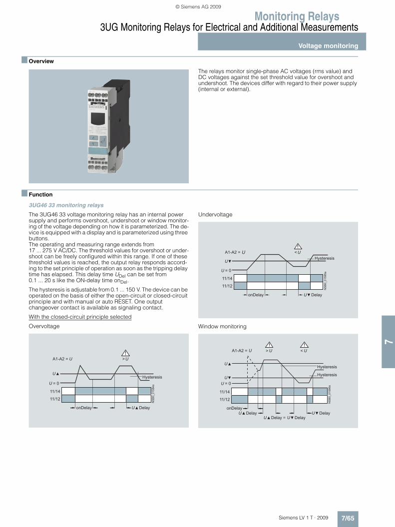
Monitoring Relays
7/65Siemens LV 1 T · 2009
3UG Monitoring Relays for Electrical and Additional Measurements
Voltage monitoring
7
■ Overview
The relays monitor single-phase AC voltages (rms value) and DC voltages against the set threshold value for overshoot and undershoot. The devices differ with regard to their power supply (internal or external).
■ Function
3UG46 33 monitoring relays
The 3UG46 33 voltage monitoring relay has an internal power supply and performs overshoot, undershoot or window monitor-ing of the voltage depending on how it is parameterized. The de-vice is equipped with a display and is parameterized using three buttons.The operating and measuring range extends from 17 ... 275 V AC/DC. The threshold values for overshoot or under-shoot can be freely configured within this range. If one of these threshold values is reached, the output relay responds accord-ing to the set principle of operation as soon as the tripping delay time has elapsed. This delay time UDel can be set from 0.1 ... 20 s like the ON-delay time onDel.
The hysteresis is adjustable from 0.1 ... 150 V. The device can be operated on the basis of either the open-circuit or closed-circuit principle and with manual or auto RESET. One output changeover contact is available as signaling contact.
With the closed-circuit principle selected
Overvoltage
Undervoltage
Window monitoring
NS
B0_
0158
4a
11/14
11/12
= 0
A1-A2 = >
Hysteresis
DelayonDelay
NS
B0_
0158
5a
11/14
11/12
= 0
A1-A2 = <Hysteresis
DelayonDelay
A1-A2 =
NS
B0_
0158
6a
>
11/14
11/12
= 0
<
Hysteresis
Hysteresis
DelayonDelay
Delay =Delay
Delay
LV1T_2009_Gesamtbuch_EN.book Seite 65 Donnerstag, 26. Februar 2009 2:00 14
© Siemens AG 2009

Monitoring Relays3UG Monitoring Relays for Electrical and Additional Measurements
Voltage monitoring
7/66 Siemens LV 1 T · 2009
7
3UG46 31/3UG46 32 monitoring relays
The 3UG46 31/3UG46 32 voltage monitoring relay is supplied with an auxiliary voltage of 24 V AC/DC or 24 ... 240 V AC/DC and performs overshoot, undershoot or window monitoring of the voltage depending on how it is parameterized. The device is equipped with a display and is parameterized using three buttons.The measuring range extends from 0.1 V ... 60 V or 10 ... 600 V AC/DC. The threshold values for overshoot or under-shoot can be freely configured within this range. If one of these threshold values is reached, the output relay responds accord-ing to the set principle of operation as soon as the delay time has elapsed. This delay time UDel can be set from 0.1 ... 20 s.The hysteresis can be set from 0.1 ... 30 V or 0.1 ... 300 V. The device can be operated on the basis of either the open-circuit or closed-circuit principle and with manual or auto RESET. One out-put changeover contact is available as signaling contact.
With the closed-circuit principle selected
Overvoltage
Undervoltage
Window monitoring
NS
B0_
0158
1a
11/14
11/12
= 0
A1-A2
>
Hysteresis
Delay
NS
B0_
0158
2a
11/14
11/12
= 0
A1-A2
<Hysteresis
Delay
NS
B0_
0158
3b
>
11/14
11/12
A1-A2
<
Hysteresis
Hysteresis
Delay DelayDelay = Delay
LV1T_2009_Gesamtbuch_EN.book Seite 66 Donnerstag, 26. Februar 2009 2:00 14
© Siemens AG 2009

Monitoring Relays
7/67Siemens LV 1 T · 2009
3UG Monitoring Relays for Electrical and Additional Measurements
Voltage monitoring
7
■ Technical specifications
1) Absolute limit values. 2) Important: This is a Class A product. In the household environment this device may cause radio interference. In this case the user must introduce suitable measures.
3UG46 31-.AA
3UG46 31-.AW
3UG46 32-.AA
3UG46 32-.AW
3UG46 33
General dataRated control supply voltage Us V 24 AC/DC 24...240
AC/DC24 AC/DC 24...240
AC/DC17 ... 2751)
AC/DC
Rated frequency for AC Hz 50/60 40 ... 500
Operating range V 20.4 ... 27.6 20.4 ... 264 20.4 ... 27.6 20.4 ... 264 17...275
Rated power in W/VA VA 2/4
Width mm 22.5
RESET Automatic/manual
Availability time after application of Us ms 1000
Response time once a switching threshold is reached ms Max. 450
Adjustable tripping delay time s 0.1 … 20
Adjustable ON-delay time s -- 0.1 ... 20
Mains buffering time, minimum ms 10
Rated insulation voltage UiDegree of pollution 3 Overvoltage category III acc. to EN 60664-1
V 690
Rated impulse withstand voltage Uimp kV 6
Protective separation acc. to EN 60947-1, Annex N V 300
Permissible ambient temperature • During operation °C -25 … +60• During storage °C -40 … +85
EMC tests2) IEC 60947-1/IEC 61000-6-2/IEC 61000-6-4
Degree of protection• Enclosure IP40• Terminals IP20
Vibration resistance acc. to IEC 60068-2-6 1 ... 6 Hz: 15 mm; 6 ... 500 Hz: 2 g
Shock resistance acc. to IEC 60068-2-27 12 shocks (half-sine 15 g/11 ms)
Connection type Screw terminals
• Terminal screw M 3 (standard screwdriver, size 2 and Pozidriv 2)• Solid mm2 1 x (0.5 ... 4)/2 x (0.5 ... 2.5)• Finely stranded with end sleeve mm2 1 x (0.5 ... 2.5)/2 x (0.5 ... 1.5)• AWG cables, solid or stranded AWG 2 x (20 ... 14)• Tightening torque Nm 0.8 … 1.2
Connection type Spring-type terminals
• Solid mm2 2 x (0.25 ... 1.5)• Finely stranded, with end sleeves acc. to DIN 46228 mm2 2 x (0.25 ... 1.5)• Finely stranded mm2 2 x (0.25 ... 1.5)• AWG cables, solid or stranded AWG 2 x (24 ... 16)Measuring circuitPermissible measuring range single-phase AC/DC voltage V 0.1 … 68 10 … 650 17 … 275
Setting range single-phase voltage V 0.1 ... 60 10 ... 600 17 ... 275
Measuring frequency Hz 40 ... 500 40 ... 500
Measuring accuracy % 5
Repeat accuracy at constant parameters % 1
Accuracy of digital display ±1 digit
Deviations for temperature fluctuations %/°C ±0.1
Hysteresis for single-phase voltage V 0.1 ... 30 0.1 ... 300 0.1 ... 150Control circuitLoad capacity of the output relay• Conventional thermal current Ith A 5
Rated operational current Ie at• AC-15/24 ... 400 V A 3• DC-13/24 V A 1• DC-13/125 V A 0.2• DC-13/250 V A 0.1
Minimum contact load at 17 V DC mA 5
Output relay with DIAZED fuse gL/gG operational class
A 4
Electrical endurance AC15 Million operating cycles
0.1
Endurance with contactor relay Million operating cycles
10
LV1T_2009_Gesamtbuch_EN.book Seite 67 Donnerstag, 26. Februar 2009 2:00 14
© Siemens AG 2009

Monitoring Relays3UG Monitoring Relays for Electrical and Additional Measurements
Voltage monitoring
7/68 Siemens LV 1 T · 2009
7
■ Dimensional drawings
■ Schematics
Note: It is not necessary to protect the measuring circuit for device protection. The protective device for line protection depends on the cross-section used.
Position of the terminals
NSB0_01729a
A B74
865
62 110
1522,5
72
1)
3UG46 313UG46 323UG46 33A B
83 92
84 94
Screw-type terminal
Spring-loaded terminal
Removable terminal
Type
1) For standard mounting rail according to EN 60715.
3UG46 31-.AA303UG46 32-.AA30
3UG46 31-.AW30 3UG46 32-.AW30
3UG46 33
NSB0_01532b
12
11
14
A1(+)
U
IN(+)
A2(–) M(–)
< U >
AC/DC Last
NSB0_01614a
12
11
14
A1(+)
U
IN(+)
A2(–) M(–)< U >
AC/DC Last
NSB0_01533b
12
11
14
A1(+)
A2(–)
< U >
AC/DC
3UG46 313UG46 32
3UG46 33
���������
� �
�
� � �
� � � � �
���������
� �
�
� � � � �
LV1T_2009_Gesamtbuch_EN.book Seite 68 Donnerstag, 26. Februar 2009 2:00 14
© Siemens AG 2009

Monitoring Relays
7/69Siemens LV 1 T · 2009
3UG Monitoring Relays for Electrical and Additional Measurements
Current monitoring
7
■ Overview
The relays monitor single-phase AC currents (rms value) and DC currents against the set threshold value for overshoot and under-shoot. They differ with regard to their measuring ranges and sup-ply voltage types.
■ Function
3UG46 21/3UG46 22 monitoring relays
The 3UG46 21/3UG46 22 current monitoring relay is supplied with an auxiliary voltage of 24 V AC/DC or 24 ... 240 V AC/DC and performs overshoot, undershoot or window monitoring of the current depending on how it is parameterized. The device is equipped with a display and is parameterized using three buttons.
The measuring range extends from 3 ... 500 mA or 0.05 ... 10 A. The rms value of the current is measured. The threshold values for overshoot or undershoot can be freely configured within this range. If one of these threshold values is reached, the output re-lay responds according to the set principle of operation as soon as the tripping delay time IDel has elapsed. This time and the ON-delay time onDel are adjustable from 0.1 ... 20 s.
The hysteresis is adjustable from 0.1 ... 250 mA or 0.01 ... 5 A. The device can be operated with manual or auto RESET and on the basis of either the open-circuit or closed-circuit principle. Following options are available: Response of the output relay when the supply voltage Us = ON is applied or not until the lower measurement range limit of the measuring current (I > 3 mA/50 mA) is reached. One output changeover contact is available as signaling contact.
With the closed-circuit principle selectedupon application of the supply voltage
Current overshoot
Current undershoot
Window monitoring
NS
B0_
0157
9a11/14
A1-A2
11/12
=0
>
Hysteresis
DelayonDelay
NS
B0_
0158
0a
= 0
11/14
A1-A2
11/12
<
Hysteresis
DelayonDelay
NS
B0_
0162
6a
>
11/14
11/12
= 0
A1-A2
<
Hysteresis
Hysteresis
DelayDelayDelayDelay =
onDelay
LV1T_2009_Gesamtbuch_EN.book Seite 69 Donnerstag, 26. Februar 2009 2:00 14
© Siemens AG 2009

Monitoring Relays3UG Monitoring Relays for Electrical and Additional Measurements
Current monitoring
7/70 Siemens LV 1 T · 2009
7
■ Technical specifications
1) Important: This is a Class A product. In the household environment this device may cause radio interference. In this case the user must introduce suitable measures.
2) With protective separation.3) With simple separation.
3UG46 21-.AA 3UG46 21-.AW 3UG46 22-.AA 3UG46 22-.AWGeneral dataRated control supply voltage Us V 24 24 … 240 24 24 … 240
Rated frequency Hz 50/60
Operating range V 20.4 ... 26.4 20.4 ... 264 20.4 ... 26.4 20.4 ... 264
Rated power W/VA 2/4
Width mm 22.5
RESET Automatic/manual
Availability time after application of Us ms 1000
Response time once a switching threshold is reached ms Max. 450
Adjustable tripping delay time/ON-delay time s 0.1 … 20
Mains buffering time, minimum ms 10
Rated insulation voltage UiDegree of pollution 3; overvoltage category III acc. to EN 60664-1
V 690
Rated impulse withstand voltage Uimp kV 6
Protective separation acc. to EN 60947-1, Annex N V 300
Permissible ambient temperature• During operation °C -25 … +60• During storage °C -40 … +85
EMC tests1) IEC 60947-1/IEC 61000-6-2/IEC 61000-6-4
Degree of protection• Enclosure IP40• Terminals IP20
Vibration resistance acc. to IEC 60068-2-6 1 ... 6 Hz: 15 mm; 6 ... 500 Hz: 2 g
Shock resistance acc. to IEC 60068-2-27 12 shocks (half-sine 15 g/11 ms)
Connection type Screw terminals
• Terminal screw M 3 (standard screwdriver, size 2 and Pozidriv 2)• Solid mm2 1 x (0.5 ... 4)/2 x (0.5 ... 2.5)• Finely stranded with end sleeve mm2 1 x (0.5 ... 2.5)/2 x (0.5 ... 1.5)• AWG cables, solid or stranded AWG 2 x (20 ... 14)• Tightening torque Nm 0.8 … 1.2
Connection type Spring-type terminals
• Solid mm2 2 x (0.25 ... 1.5)• Finely stranded, with end sleeves acc. to DIN 46228 mm2 2 x (0.25 ... 1.5)• Finely stranded mm2 2 x (0.25 ... 1.5)• AWG cables, solid or stranded AWG 2 x (24 ... 16)Measuring circuitMeasuring range for single-phase AC/DC current A 0.003 … 0.6 0.05 … 15
Setting range for single-phase current A 0.003 ... 0.5 0.05 ... 10
Load supply voltage V 24 Max. 3002)
Max. 5003)24 Max. 3002)
Max. 5003)
Measuring accuracy % 5
Repeat accuracy at constant parameters % 1
Accuracy of digital display ±1 digit
Deviations for temperature fluctuations %/°C ±0.1
Hysteresis for single-phase current 0.1 ... 250 mA 0.01 ... 5 A
Permissible overcurrent, continuous A 0.6 15
Permissible overcurrent, < 1 s A 5 50
Protection against destruction, DIAZED gL/gG A 2 16
Measuring circuit internal resistance, shunt mΩ 500 5Control circuitLoad capacity of the output relay• Conventional thermal current Ith A 5
Rated operational current Ie at• AC-15/24 ... 400 V A 3• DC-13/24 V A 1• DC-13/125 V A 0.2• DC-13/250 V A 0.1
Minimum contact load at 17 V DC mA 5
Output relay with DIAZED fuse gL/gG A 4
Electrical endurance AC15 (million operating cycles) 0.1
Endurance with contactor relay (million operating cycles) 10
LV1T_2009_Gesamtbuch_EN.book Seite 70 Donnerstag, 26. Februar 2009 2:00 14
© Siemens AG 2009

Monitoring Relays
7/71Siemens LV 1 T · 2009
3UG Monitoring Relays for Electrical and Additional Measurements
Current monitoring
7
■ Dimensional drawings
■ Schematics
Position of the terminals
NSB0_01728a
A B74865
62 110
1522,5
72
1)
3UG46 213UG46 22A B
83 92
84 94
Screw-type terminal
Spring-loaded terminal
Removable terminal
Type
1) For standard mounting rail according to EN 60715.
3UG46 21-.AA303UG46 22-.AA30Operation with separate control circuit and load circuit
Operation with joint control circuit and load circuit
3UG46 21-.AW30 3UG46 22-.AW30Single-phase operation 3-phase operation
< >
11
14
NSB0_01534b
12 A2 M
A1 IN
MLoad
ULoad
24 V AC/DC
Load
< >
11
14
NSB0_01708
12 A2 M
A1 IN
24 V AC/DC
optional
Load
NSB0_01535b
11
14 M
12
A1
A2
< >
IN
MLoad
AC/DC
LoadULoad
NS
B0_
0170
7
< >
A1 IN
A2 M
L3L2L1AC/DC
11
1412
Load
3UG46 213UG46 22
����������
� �
�
� � �
� � � � �
LV1T_2009_Gesamtbuch_EN.book Seite 71 Donnerstag, 26. Februar 2009 2:00 14
© Siemens AG 2009

Monitoring Relays3UG Monitoring Relays for Electrical and Additional Measurements
Current monitoring
7/72 Siemens LV 1 T · 2009
7
Wiring diagram for 24 V AC/DC (only 3UG46 2.-.AA30)
From the following circuit diagrams it is clear that loads in mea-suring circuits have to be in the current flow upstream from the monitoring relay. Otherwise, the monitoring relay could be de-stroyed and the short-circuit current could cause damage to the plant.
Configuring note:
A2 and M are electrically connected internally!
For applications in which the load to be monitored and the mon-itoring relay are supplied from the same power supply, there is no need for connection A2!
The load current must always flow through M or the monitoring relay may be destroyed!
< >
NSB0_01199e
A2 M
A1 IN
MLoad
ULoad
AC/DC
Load
NS
B0_
0120
0e
A2
M
L1
L2
L3
IN
A1
< >
o.k.
3UG3
24 V AC/DC
Load
o.k.
< >
A2 M
A1 IN
NS
B0_
0119
7e Load
24 V AC/DC
< >
A2
A1
NSB
0_01
198e
o.k.
M
L1 L2 L3
IN
24 V AC/DC
Load
LV1T_2009_Gesamtbuch_EN.book Seite 72 Donnerstag, 26. Februar 2009 2:00 14
© Siemens AG 2009

Monitoring Relays
7/73Siemens LV 1 T · 2009
3UG Monitoring Relays for Electrical and Additional Measurements
Power factor and active current monitoring
7
■ Overview
The 3UG46 41 power factor and active current monitoring de-vice enables the load monitoring of motors.
Whereas power factor monitoring is used above all for monitor-ing no-load operation, the active current monitoring option can be used to observe and evaluate the load factor over the entire torque range.
■ Function
3UG46 41 monitoring relays
The 3UG46 41 monitoring relay is self-powered and serves the single-phase monitoring of the power factor or performs over-shoot, undershoot or window monitoring of the active current de-pending on how it is parameterized.
The load to be monitored is connected in front of the IN terminal. The load current flows over the IN and Ly/N terminals. The set-ting range for the power factor is 0.1 ... 0.99 and for the active current Ires 0.2 ... 10 A.
If the supply voltage is switched on and no load current is flow-ing, the display indicates I < 0.2 and a symbol for overshoot, un-dershoot or window monitoring.
If the motor is now switched on and the current exceeds 0.2 A, the set ON-delay time begins. During this time, an undershoot-ing or overshooting of the set limit values will not lead to a relay response of the changeover contact.
If the operational flowing active current and/or the power factor value falls below or exceeds the respective set threshold value, the spike delay begins. When this time has expired, the relay changes its switch position. The relevant measured variables for overshooting and undershooting in the display flashes. If the monitoring of active current undershooting is deactivated (Ires▼= OFF) and the load current drops below the lower mea-surement range threshold (0.2 A), then the CO contacts remain unchanged. If a threshold value is set for the monitoring of active current undershooting, then undershooting of the measurement range threshold (0.2 A) will result in a response of the CO contacts.
The relay operates either according to the open-circuit or closed-circuit principle.
If the device is set to Auto-RESET (Memory = No), depending on the set principle of operation, the switching relay returns to its ini-tial state and the flashing ends when the hysteresis threshold is reached.
If manual reset is selected in the menu (Memory = Yes), the switching relay remains in its current switching state and the cur-rent measured value and the symbol for undershooting and overshooting continues to flash, even when the measured vari-able reaches a permissible value again. This stored fault status can be reset by pressing the UP▲ and DOWN▼ key simulta-neously for 2 seconds, or by switching the supply voltage off and back on again.
With the closed-circuit principle selected
Behavior upon undershooting of the measurement range limit with activated monitoring of Ires▼
Behavior upon undershooting of the measurement range limit with deactivated monitoring of active current undershooting
NS
B0_
0165
8b
21/22
21/24
11/12
11/14
Lx-Ly/N
I = 0,2 A
I = 0
I < 0,2 A
Ires
onDelayonDelayN
SB
0_01
917a
21/22
21/24
11/12
11/14
Lx-Ly/N
I = 0,2 A
I = 0
I < 0,2 A
Ires = off
onDelayonDelay
LV1T_2009_Gesamtbuch_EN.book Seite 73 Donnerstag, 26. Februar 2009 2:00 14
© Siemens AG 2009

Monitoring Relays3UG Monitoring Relays for Electrical and Additional Measurements
Power factor and active current monitoring
7/74 Siemens LV 1 T · 2009
7
Overshooting of active current
Undershooting of active current
Window monitoring of active current
Legend
cos ϕ: p. f.
Overshooting of power factor
Undershooting of power factor
Window monitoring of power factor
NS
B0_
0165
9a
21/24
21/22
11/14
11/12
> res
= 0
res
DelayonDelay
Hysteresis
NS
B0_
0166
0a
21/24
21/22
11/14
11/12
< res
= 0
res
DelayonDelay
Hysteresis
NS
B0_
0166
1a
21/24
21/22
11/14
11/12
< res
= 0
> res
res
res
DelayonDelay Delay
Hysteresis
Hysteresis
NS
B0_
0166
2a
21/24
21/22
11/14
11/12
> cos
cos = 0
cos
p.f.
DelayonDelay
Hysteresis 0,10
cos = 0
NS
B0_
0166
3a
21/24
21/22
11/14
11/12
< cos
cosp.f.
Hysteresis 0,10
DelayonDelay
cos = 0
NS
B0_
0166
4a
21/24
21/22
11/14
11/12
< cos
cos
p.f.cos
> cos
Hysteresis0,10
DelayonDelay Delay
LV1T_2009_Gesamtbuch_EN.book Seite 74 Donnerstag, 26. Februar 2009 2:00 14
© Siemens AG 2009

Monitoring Relays
7/75Siemens LV 1 T · 2009
3UG Monitoring Relays for Electrical and Additional Measurements
Power factor and active current monitoring
7
■ Technical specifications
1) Important: This is a Class A product. In the household environment this device may cause radio interference. In this case the user must introduce suitable measures.
Type 3UG46 41General dataRated control supply voltage Us V 90 … 690
Rated frequency Hz 50/60
Rated power, typical• At 200 V AC VA 2.0• At 400 V AC VA 2.7• At 460 V AC VA 3.1
Width mm 22.5
RESET Automatic/manual
Principle of operation Closed-circuit principle, open-circuit principle
Availability time after application of Us ms 1000
Response time once a switching threshold is reached ms Max. 450
Adjustable tripping delay time s 0.1 ... 20
Adjustable ON-delay time s 0 ... 99
Mains buffering time, minimum ms 10
Rated insulation voltage UiDegree of pollution 3Overvoltage category III acc. to EN 60664-1
V 690
Rated impulse withstand voltage kV 6
Permissible ambient temperature • During operation °C -25 … +60• During storage °C -40 … +85
EMC tests1) IEC 60947-1/IEC 61000-6-2/IEC 61000-6-4
Degree of protection• Enclosure IP40• Terminals IP20
Vibration resistance acc. to IEC 60068-2-6 1 ... 6 Hz: 15 mm; 6 ... 500 Hz: 2 g
Shock resistance acc. to IEC 60068-2-27 12 shocks (half-sine 15 g/11 ms)
Connection type Screw terminals
• Terminal screw M 3 (standard screwdriver, size 2 and Pozidriv 2)• Solid mm2 1 x (0.5 ... 4)/2 x (0.5 ... 2.5)• Finely stranded with end sleeve mm2 1 x (0.5 ... 2.5)/2 x (0.5 ... 1.5)• AWG cables, solid or stranded AWG 2 x (20 ... 14)• Tightening torque Nm 0.8 … 1.2
Connection type Spring-type terminals
• Solid mm2 2 x (0.25 ... 1.5)• Finely stranded, with end sleeves acc. to DIN 46228 mm2 2 x (0.25 ... 1.5)• Finely stranded mm2 2 x (0.25 ... 1.5)• AWG cables, solid or stranded AWG 2 x (24 ... 16)Measuring circuitMeasurable active current Ires A 0.2 ... 10
Max. permissible load current A 10
Peak current < 1 s A 50
Adjustable response value Phase displacement angle
0.1 ... 0.99
DIAZED protection, gL/gG operational class A 16
Measuring accuracy % 10
Repeat accuracy at constant parameters % 1
Accuracy of digital display ± 1 digit
Deviations for temperature fluctuations %/°C ±0.1
Hysteresis Phase angle
0.10
Hysteresis Active current monitoring
A 0.1 ... 2.0
LV1T_2009_Gesamtbuch_EN.book Seite 75 Donnerstag, 26. Februar 2009 2:00 14
© Siemens AG 2009

Monitoring Relays3UG Monitoring Relays for Electrical and Additional Measurements
Power factor and active current monitoring
7/76 Siemens LV 1 T · 2009
7
■ Dimensional drawings
Type 3UG46 41Control circuitNumber of CO contacts for auxiliary contacts 2
Load capacity of the output relay• Conventional thermal current Ith A 5
Rated operational current Ie at• AC-15/24 ... 400 V A 3• DC-13/24 V A 1• DC-13/125 V A 0.2• DC-13/250 V A 0.1
Minimum contact load at 17 V DC mA 5
Output relay with DIAZED fusegL/gG operational class
A 4
Electrical endurance AC-15 Million operat-ing cycles
0.1
Mechanical endurance Million operat-ing cycles
10
NSB0_01699b
A B74
865
62 110
1522,5
72
1)
3UG46 41A B
83 92
84 94
1) For standard mounting rail according to EN 60715.
Screw-type terminal
Spring-loaded terminal
Removable terminal
Type
LV1T_2009_Gesamtbuch_EN.book Seite 76 Donnerstag, 26. Februar 2009 2:00 14
© Siemens AG 2009

Monitoring Relays
7/77Siemens LV 1 T · 2009
3UG Monitoring Relays for Electrical and Additional Measurements
Power factor and active current monitoring
7
■ Schematics
Legend
cos ϕ: p. f.
Position of the terminals
Single-phase motors 3-phase motors 3-phase motors with transformers for currents > 10 A
M1~
Lx IN
12
14
22
24
N/L
L/N
21
Ly/N
113UG46 41
cos / r
cos / r
NSB0_01654b
Lx IN
12
14
22
24
LnLnLnn = 1,2,3
21
M3~
11
Ly/N
3UG46 41
cos / r
cos / r
NSB0_01655b
Lx IN
12
14
22
2421
M3~
Ly/N
11
3UG46 41
NSB0_01656b
cos / r
cos / r
LnLnLnn = 1,2,3
3UG46 41
NS
B0_
0165
7
Lx
12 14
IN
22 21 24
11
Ly/N
LV1T_2009_Gesamtbuch_EN.book Seite 77 Donnerstag, 26. Februar 2009 2:00 14
© Siemens AG 2009

Monitoring Relays3UG Monitoring Relays for Electrical and Additional MeasurementsResidual current monitoring:Residual-current monitoring relays
7/78 Siemens LV 1 T · 2009
7
■ Overview
The 3UG46 24 residual current monitoring relay is used together with the 3UL22 summation current transformer for plant monitoring.
■ Function
3UG46 24 monitoring relays
The main conductor and any neutral conductor to which a load is connected, are routed through the opening of the annular strip-wound core of a summation current transformer. A second-ary winding is placed around this annular strip-wound core to which the monitoring relay is connected.
If operation of a plant is fault-free, the sum of the inflowing and outward currents equals zero. In this case, no voltage is induced in the secondary winding of the summation current transformer.
However, if an insulation fault occurs downstream of the residual current operated circuit breaker, the sum of the inflowing cur-rents is greater than that of the outward currents.
The differential current - the residual current - induces a second-ary current in the secondary winding of the transformer. This cur-rent is evaluated in the monitoring relay and is used on the one hand to display the actual residual current and on the other, to switch the relay if the set warning or tripping threshold is over-shot.
If the measured residual current exceeds the set warning value, the associated changeover contact instantly changes the switching state and an indication appears on the display. If the measured residual current exceeds the set tripping value, the set delay time begins and the associated relay symbol flashes. On expiry of this time, the associated changeover contact changes the switching state.
ON-delay time for motor start
To be able to start a motor, once the auxiliary voltage has been applied for an adjustable ON-delay time, and depending on whether the open-circuit or closed-circuit principle is selected, the output relay switches to the GO state.
The changeover contacts do not react if the set threshold value is overshot during this period.
LV1T_2009_Gesamtbuch_EN.book Seite 78 Donnerstag, 26. Februar 2009 2:00 14
© Siemens AG 2009

Monitoring Relays
7/79Siemens LV 1 T · 2009
3UG Monitoring Relays for Electrical and Additional MeasurementsResidual current monitoring:
Residual-current monitoring relays
7
With the closed-circuit principle selected
Residual current monitoring with Auto-RESET (Memory = no)
If the device is set to Auto-RESET (Memory = No), the relay switches for the tripping value once the value falls below the set hysteresis threshold and the display stops flashing. The associ-ated relay changes its switching state if the value falls below the fixed hysteresis value of 5 % of the warning value. Any over-shoots are therefore not stored.
Note:
The neutral conductor must not be grounded downstream of the summation current transformer as this may impair the function of the residual current monitoring device.
Residual current monitoring with Manual-RESET (Memory = yes)
If Manual-RESET is selected in the menu, the output relay re-mains in its current switching state and the current measured value and the symbol for overshooting continues to flash, even when the measured residual current returns to a permissible value. This stored fault status can be reset by pressing the UP▲ and DOWN▼ key simultaneously for > 2 seconds, or by switch-ing the supply voltage off and back on again.
NS
B0_
0181
2a
11/14
Lx-Ly/N
11/12
21/24
21/22
>
= 0
!
!>
Hysteresis
Mem = no
Hysteresis = 5 %
onDelay Delay
NS
B0_
0181
3a
11/14
Lx-Ly/N
11/12
21/24
21/22
>
= 0
!
!>
Reset
Hysteresis
Mem = yes
Hysteresis = 5 %
onDelay Delay
LV1T_2009_Gesamtbuch_EN.book Seite 79 Donnerstag, 26. Februar 2009 2:00 14
© Siemens AG 2009
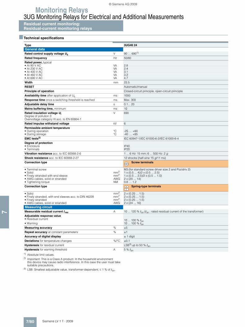
Monitoring Relays3UG Monitoring Relays for Electrical and Additional MeasurementsResidual current monitoring:Residual-current monitoring relays
7/80 Siemens LV 1 T · 2009
7
■ Technical specifications
1) Absolute limit values.2) Important: This is a Class A product. In the household environment
this device may cause radio interference. In this case the user must take suitable precautions.
3) LSB: Smallest adjustable value, transformer-dependent, ≤ 1 % of IΔn.
Type 3UG46 24General dataRated control supply voltage Us V 90 … 6901)
Rated frequency Hz 50/60
Rated power, typical• At 90 V AC VA 2.8• At 230 V AC VA 2.4• At 400 V AC VA 3.1• At 460 V AC VA 3.2• At 690 V AC VA 4.7
Width mm 22.5
RESET Automatic/manual
Principle of operation Closed-circuit principle, open-circuit principle
Availability time after application of Us ms 1000
Response time once a switching threshold is reached ms Max. 300
Adjustable delay time s 0.1... 20
Mains buffering time, minimum ms 10
Rated insulation voltage UiDegree of pollution 3Overvoltage category III acc. to EN 60664-1
V 690
Rated impulse withstand voltage kV 6
Permissible ambient temperature • During operation °C -25 … +60• During storage °C -40 … +85
EMC tests2) IEC 60947-1/IEC 61000-6-2/IEC 61000-6-4
Degree of protection• Enclosure IP40• Terminals IP20
Vibration resistance acc. to IEC 60068-2-6 1 ... 6 Hz: 15 mm; 6 ... 500 Hz: 2 g
Shock resistance acc. to IEC 60068-2-27 12 shocks (half-sine 15 g/11 ms)
Connection type Screw terminals
• Terminal screw M3 (for standard screw driver size 2 and Pozidriv 2)• Solid mm2 1 x (0.5 ... 4)/2 x (0.5 ... 2.5)• Finely stranded with end sleeve mm2 1 x (0.5 ... 2.5)/2 x (0.5 ... 1.5)• AWG cables, solid or stranded AWG 2 x (20 ... 14)• Tightening torque NM 0.8 … 1.2
Connection type Spring-type terminals
• Solid mm2 2 x (0.25 ... 1.5)• Finely stranded, with end sleeves acc. to DIN 46228 mm2 2 x (0.25 ... 1.5)• Finely stranded mm2 2 x (0.25 ... 1.5)• AWG cables, solid or stranded AWG 2 x (24 ... 16)Measuring circuitMeasurable residual current Ires A 10 ... 120 % IΔn (IΔn : rated residual current of the transformer)
Adjustable response value • Residual current 10 ... 100 % IΔn • Warning 10 ... 100 % IΔn
Measuring accuracy % ±5
Repeat accuracy at constant parameters % ±1
Accuracy of digital display ± 1 digit
Deviations for temperature changes %/°C ±0.1
Hysteresis for residual current LSB3) up to 50 % IΔn
Hysteresis for warning threshold A 5 % IΔn
LV1T_2009_Gesamtbuch_EN.book Seite 80 Donnerstag, 26. Februar 2009 2:00 14
© Siemens AG 2009

Monitoring Relays
7/81Siemens LV 1 T · 2009
3UG Monitoring Relays for Electrical and Additional MeasurementsResidual current monitoring:
Residual-current monitoring relays
7
■ Dimensional drawings
3UG46 24
Type 3UG46 24Control circuitNumber of CO contacts for auxiliary contacts 2
Load capacity of the output relay
Conventional thermal current IthA 5
Rated operational current Ie at• AC-15/24 ... 400 V A 3• DC-13/24 V A 1• DC-13/125 V A 0.2• DC-13/250 V A 0.1
Minimum contact load at 17 V DC mA 5
Output relay with DIAZED fuse gL/gG operational class
A 4
Electrical endurance AC-15 Million operat-ing cycles
0.1
Mechanical endurance Million operat-ing cycles
10
NSB0_01828
A B74
86536
62 110
1522,5
82
3UG46 24A B
84 103
83 102Screw-type terminal
Spring-loaded terminal
Removable terminal
1) For standard mounting rail according to EN 60715.
Type
LV1T_2009_Gesamtbuch_EN.book Seite 81 Donnerstag, 26. Februar 2009 2:00 14
© Siemens AG 2009

Monitoring Relays3UG Monitoring Relays for Electrical and Additional MeasurementsResidual current monitoring:Residual-current monitoring relays
7/82 Siemens LV 1 T · 2009
7
■ Schematics
3UG46 24
Note: It is not necessary to protect the measuring circuit for device protection. The protective device for line protection depends on the cross-section used.
Circuit example
Position of the terminals
11
12 14
Lx C1 C2
Ly/N
3UG46 24
AC
AC
NSB0_01808a
21
22 24
L1 L2 L3 N
AC 24 V
F1
3UL22Z3
A2
R1
R2
Lx Ly/N
3UG46 24 C1 Z1
C2 Z2
NS
B0_
0183
2
Load
220 >3 W --
Type R1 R23UL22 0.-1A 3UL22 0.-2A3UL22 0.-3A
0,3 A0,5 A 1 A
3UL22 0.-1B3UL22 0.-2B3UL22 0.-3B3UL22 0.-4B3UL22 0.-5B
6 A10 A16 A25 A40 A
22 >6 W 22 >6 W
-
- -
NS
B0_
0182
5
C1 C2Lx Ly/N
22 21 2412 11 14
LV1T_2009_Gesamtbuch_EN.book Seite 82 Donnerstag, 26. Februar 2009 2:00 14
© Siemens AG 2009

Monitoring Relays
7/83Siemens LV 1 T · 2009
3UG Monitoring Relays for Electrical and Additional MeasurementsResidual current monitoring:
3UL22 summation current transformers
7
■ Overview
The 3UL22 summation current transformers detect fault currents in machines and plants. Together with the 3UG46 24 residual current monitoring relay or the SIMOCODE 3UF motor manage-ment and control device they enable residual-current and ground-fault monitoring.
■ Technical specifications
■ Dimensional drawings
3UL22 summation current transformer
Summation current transformers
Type 3UL22 01 3UL22 02 3UL22 03
Rated insulation voltage Ui AC 50/60 Hz
690 V 1000 V
Rated residual current IΔnWithout response delay A 0.3 ... 1 0.3 ... 40 0.3 ... 40
Permissible ambient temperature °C -20 ... +70
Feed-through openings mm 40 65 120
For Protodur cablesCan be fed through Max. mm² 4 x 95 4 x 240 8 x 300
NSB0_00364b
a1
a6
a4 a5
a2 a3
b5b 1
b 2b 3b 4
c 1 c 2 c 3
A2
Z2Z1
Z3
Type
3UL22 013UL22 023UL22 03
a1
100125200
a3
101020
a2
7595
165
a4
151520
c1
657085
a6
80100170
a5
for M4for M4for M4
b1
85110200
b2
72.597.5
100
b3
42.555
100
b4
7.57.5
10
b5
4065
120
c2
506070
c3
404555
LV1T_2009_Gesamtbuch_EN.book Seite 83 Donnerstag, 26. Februar 2009 2:00 14
© Siemens AG 2009
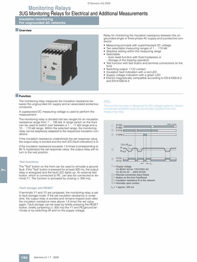
Monitoring Relays3UG Monitoring Relays for Electrical and Additional MeasurementsInsulation monitoringFor ungrounded AC networks
7/84 Siemens LV 1 T · 2009
7
■ Overview
Relay for monitoring the insulation resistance between the un-grounded single or three-phase AC supply and a protective con-ductor• Measuring principle with superimposed DC voltage• Two selectable measuring ranges of 1 ... 110 kΩ• Stepless setting within the measuring range• Selectable:
- Auto reset function with fixed hysteresis or- Storage of the tripping operation
• Test function with test button and terminal connections on the front
• Switching output: 1 CO contact• Insulation fault indication with a red LED• Supply voltage indication with a green LED• Electro-magnetically compatible according to EN 61000-6-2
and EN 61000-6-4
■ Function
The monitoring relay measures the insulation resistance be-tween the ungrounded AC supply and an associated protective conductor.
A superposed DC measuring voltage is used to perform the measurement.
The monitoring relay is divided into two ranges for an insulation resistance range from 1 ... 100 kΩ. A range switch on the front can be used to switch over between a 1 ... 11 kΩ range and a 10 ... 110 kΩ range. Within the selected range, the monitoring relay can be steplessly adapted to the respective insulation con-ditions.
If the insulation resistance undershoots the set response value, the output relay is excited and the red LED (fault indication) is lit.
If the insulation resistance exceeds 1.6 times (corresponding to 60 % hysteresis) the set response value, the output relay will re-turn to the rest position.
Test functions
The "Test" button on the front can be used to simulate a ground fault. If the "Test" button is pressed for at least 300 ms, the output relay is energized and the fault LED lights up. An external test button, which is connected to PE, can also be connected to ter-minal Y1. The function is activated by closing (> 300 ms).
Fault storage and RESET
If terminals Y1 and Y2 are jumpered, the monitoring relay is set to fault storage mode. If the set insulation resistance is under-shot, the output relay is excited and remains tripped even after the insulation resistance rises above 1.6 times the set value again. Fault storage can be reset by briefly pressing the RESET button, briefly jumpering (< 300 ms) the Y1 and PE/ground ter-minals or by switching off and on the supply voltage.
Note:
The monitoring relay is designed for AC voltage systems. Series-connected rectifiers must be electrically isolated from the measuring relay.
= Supply voltage A1-B2/A1-A2 for 115V/230V AC A1-A2 for 24 … 240V AC/DC= Remote connection-Save-Reset= Button on the front Test/Reset= Insulation resistance R of the network= Normally open contact
tTest
tTest = > approx. 300 ms
A1/A2A1/B2
11/1411/12
Y1/Y2
Y1/PE
1,6 x Rvalue
RRvalue
2
1
3
4
5
2
1
3
4
5
NSB0_01393a
LV1T_2009_Gesamtbuch_EN.book Seite 84 Donnerstag, 26. Februar 2009 2:00 14
© Siemens AG 2009

Monitoring Relays
7/85Siemens LV 1 T · 2009
3UG Monitoring Relays for Electrical and Additional MeasurementsInsulation monitoring
For ungrounded AC networks
7
■ Technical specifications
■ Dimensional drawings
■ Schematics
Circuit diagram for networks up to 400 V AC
3UG30 81Control circuitOperating range of the control supply voltage -15 %... +10 %
Rated power 24 ... 240 V AC/DC VA/W 8/2
110 ... 130 V AC/DC VA 3
220 ... 240 V AC/DC VA 3
Frequency of the rated control supply voltage Hz 50 ... 60Measuring circuit L/PE• Response value kΩ 1...110
• Min. internal resistance for AC kΩ 100
• Min. internal resistance for DC kΩ 100
• Measurement DC voltage V 30
• Max. AC insulation voltage (L/PE) V 415
• Reset/test function terminals (max. 10 m) Y1-Y2
• Delay time in case of response s 1
Output relay 1 CO contact, open-circuit principleGeneral data Rated insulation voltage Ui Between supply, measurement,
and output circuitV 250 acc. to IEC 60947-1
Overvoltage category Acc. to EN 60664-1 III
Degree of pollution Acc. to IEC 60664-1 3
Impulse withstand voltage Uimp Acc. to VDE 0435, Part 303 kV 4
Degree of protection Acc. to EN 60529 IP50 enclosure, IP20 terminals
Shock resistance Acc. to IEC 60068-2-27 g/ms 10
Vibration resistance Acc. to IEC 60068-2-6 10 ... 55 Hz: 0.35 mm
Permissible ambient temperature • During operation °C -25 ... 65• During storage °C -40 ... 85
Permissible mounting positions Any
Conductor cross-section Solid mm2 2 x 0.75 ... 2.5
Finely stranded with end sleeve mm2 2 x 0.75 ... 2.5
��
��
��
��
�
��
��
��
��
��
��
L1L2L3
A1
A2B21)
N 230 VN 115 V
R
A1
A2 B2
L
PE Y2Y1
111412
NS
B0_
0139
4c
N
A1-A2 for 24...240 V AC/DC
TestReset
3 x 230/400 V AC
PE
A1-B2 for 115 V AC orA1-B2 for 230 V AC1) Only 3UG3081-1AK20.
LV1T_2009_Gesamtbuch_EN.book Seite 85 Donnerstag, 26. Februar 2009 2:00 14
© Siemens AG 2009

Monitoring Relays3UG Monitoring Relays for Electrical and Additional MeasurementsInsulation monitoringFor ungrounded DC networks
7/86 Siemens LV 1 T · 2009
7
■ Overview
Relay for monitoring the insulation resistance between un-grounded pure DC networks and a protective conductor• Measuring principle for residual current measurement• Response value can be adjusted steplessly from 10 ... 110 kΩ• Selectable
- Auto reset function with hysteresis or - Storage of the tripping operation
• Front selector switch for open-circuit and closed-circuit principle for the output relay
• Test function with test buttons on the front for L+ and L-and over terminal connections
• Switching output: 1 CO contact• Insulation fault indicator for L+ and L- through two red LEDs• Supply voltage indication with a green LED • Electro-magnetically compatible according to EN 61000-6-2
and EN 61000-6-4
■ Function
The monitoring relay measures the insulation resistance be-tween the positive and negative supply voltage in an un-grounded DC voltage network and a corresponding protective conductor.
The measurement is based on the DC residual current measure-ment principle. The response value can be adjusted steplessly in the range from 10 ... 110 kΩ and thus can be adapted to the corresponding conditions. If the insulation resistance falls below the set response value, the output relay triggers (depending on the setting of the open/closed-circuit principle selector switch) and a fault LED lights up.
A ground fault is evaluated separately for L+ and L- and indi-cated by means of a corresponding LED.
Note:
Due to the measurement principle, a symmetrical ground fault on terminals L+ and L- cannot be evaluated.
Test function
A ground fault can be simulated using the Test L+ and Test L- buttons on the front. If the test button is pressed for at least 1 s, the status of the output relay changes and the corresponding fault LED lights up.
An external test button can be connected to terminals Y1-Y3 for L+ and terminals Y4-Y3 for L-. The function is triggered by means of a NO contact.
Fault storage and RESET
If terminals Y2 and Y3 are linked, the monitoring relay is set to fault storage mode.
If the insulation resistance falls below the set value, the output re-lay triggers (depending on the setting of the open/closed circuit selector switch), and stays in this state even if the insulation re-sistance rises again above the hysteresis value (typical: 2 times the set value). This fault storage can be deleted by pressing and releasing the L+ RESET button, opening the Y2-Y3 connection or by switching off the supply voltage.
Open/closed-circuit principle selector switch
The principle of operation of the output relay can be adjusted by means of a selector switch on the front panel.
If the relay is to respond in the event of a fault (contact symbol open), the open-circuit principle must be selected. If the relay however is to trigger in the event of a fault (contact symbol closed), the closed-circuit principle must be selected.
Note:
The position of the selector switch has no effect upon the fault LEDs. The LEDs always light up if the insulation resistance on L+ or L– falls below the set value.
= Supply voltage= Button on front – Reset L+ and L-/Test L+= Button on front – Test L – Test remote connection – Test L= Test remote connection – Test L+= Test remote connection – Store, reset= Insulation resistance R of supply set response value R= Switch on front Open-circuit/closed-circuit principle= Selector switch
Open-circuit/closedcircuitprinciple11/1411/12
2
1
3
4
5
6
7
8
21
3
4
56
7
8
A1/A2
Y3/Y4Y1/Y3Y2/Y3
L+/PEL-/PE
tTest > IstTest = approx. 1 sRHyst = typically 2 x Rx
R
Rvalue
RHyst
NSB0_01395a
LV1T_2009_Gesamtbuch_EN.book Seite 86 Donnerstag, 26. Februar 2009 2:00 14
© Siemens AG 2009

Monitoring Relays
7/87Siemens LV 1 T · 2009
3UG Monitoring Relays for Electrical and Additional MeasurementsInsulation monitoring
For ungrounded DC networks
7
■ Technical specifications
■ Dimensional drawings
■ Schematics
Circuit diagram for 24 ... 240 V DC
3UG30 82Control circuitOperating range of the control supply voltage -15 %... +10 %
Rated power 24 ... 240 V AC/DC VA/W 8/2
Frequency of the rated control supply voltage Hz 50 ... 60Measuring circuit • Response value kΩ 10 ... 110
• Min. internal resistance for DC kΩ 57
• Measurement DC voltage V 24 ... 240
• Max. DC insulation voltage (L+/PE/ground, L-/PE/ground) V 300
• Reset/test function terminals (max. 10 m) Y1/Y3, Y4/Y3
• Delay time in case of response s 1
Output relay 1 changeover contact, open-circuit or closed-circuit principleGeneral data Rated insulation voltage Ui Insulation resistance
Between supply, measurement, and output circuit
V 250
Overvoltage category Acc. to EN 60664-1 III
Degree of pollution Acc. to EN 60664-1 3
Impulse withstand voltage Uimp Acc. to VDE 0435, Part 303 kV 4
Degree of protection Acc. to EN 60529 IP50 enclosure, IP20 terminals
Shock resistance Acc. to IEC 60068-2-27 g/ms 10
Vibration resistance Acc. to IEC 60068-2-6 10 ... 55 Hz: 0.35 mm
Permissible ambient temperature • During operation °C -25 ... + 65• During storage °C -40 ... + 85
Permissible mounting positions Any
Conductor cross-section Solid mm2 2 x 0.75 ... 2.5
Finely stranded with end sleeve mm2 2 x 0.75 ... 2.5
��
��
��
��
�
��
��
��
��
��
��
NS
B0_
0139
6
A1
A2
L+
PE
Y2
11
1412
Y1
Y4
Y3
Test L-
24...240 V AC/DC
R
24...240 V DC
L
L+
L-N
PE
L-
Test L+Reset
LV1T_2009_Gesamtbuch_EN.book Seite 87 Donnerstag, 26. Februar 2009 2:00 14
© Siemens AG 2009

Monitoring Relays3UG Monitoring Relays for Electrical and Additional MeasurementsLevel monitoring:Level monitoring relays
7/88 Siemens LV 1 T · 2009
7
■ Overview
The 3UG45 01 level monitoring relay is used together with 2- or 3-pole sensors to monitor the levels of conductive liquids.
■ Function
3UG45 01 monitoring relays
The principle of operation of the 3UG45 01 level monitoring relay is based on measuring the electrical resistance of the liquid be-tween two immersion sensors and a reference terminal. If the measured value is lower than the sensitivity set at the front, the output relay changes its switching state. In order to exclude electrolytic phenomena in the liquid, the sensors are supplied with alternating current.
Two-point control
The output relay changes its switching state as soon as the liquid level reaches the maximum sensor, while the minimum sensor is submerged. The relay returns to its original switching state as soon as the minimum sensor no longer has contact with the liquid.
Single-point control
If only one level is being controlled, the terminals for Min and Max on the monitoring relay are bridged. The output relay changes its switching state as soon as the liquid level is reached and returns to its original switching state once the sensor no longer has contact with the liquid.
In order to prevent premature tripping of the switching function caused by wave motion or frothing, even though the set level has not been reached, it is possible to delay this function by 0.5 ... 10 s.
For safe resetting, the supply voltage must be interrupted for at least the set delay time of +0.5 s.
Note:
It is also possible to connect other resistance sensors to the Min and Max terminals in the range 2 ... 200 kW, e. g. photoresistors, temperature sensors, encoders based on resistance etc. The monitoring relay can therefore also be used for other applica-tions apart from monitoring the levels of liquids.
LV1T_2009_Gesamtbuch_EN.book Seite 88 Donnerstag, 26. Februar 2009 2:00 14
© Siemens AG 2009

Monitoring Relays
7/89Siemens LV 1 T · 2009
3UG Monitoring Relays for Electrical and Additional MeasurementsLevel monitoring:
Level monitoring relays
7
OVER, two-point control
UNDER, two-point control
OVER, single-point control
UNDER, single-point control
11/14
A1/A2
t t
11/12
t t
NS
B0_
0179
9b
Max
Min
t = Delay 0,5 - 10 s
> 0,5 s + t
Reset
11/14
A1/A2
11/12
t
NS
B0_
0180
0b
t t t
t = Delay 0,5 - 10 s
Max
Min
> 0,5 s + t
Reset
11/14
A1/A2
t t
11/12
t t
NS
B0_
0180
1b
Max Min
t = Delay 0,5 - 10 s
> 0,5 s + t
Reset
11/14
A1/A2
t t
11/12
t t
NS
B0_
0180
2c
Max Min
t = Delay 0,5 - 10 s
> 0,5 s + t
Reset
LV1T_2009_Gesamtbuch_EN.book Seite 89 Donnerstag, 26. Februar 2009 2:00 14
© Siemens AG 2009

Monitoring Relays3UG Monitoring Relays for Electrical and Additional MeasurementsLevel monitoring:Level monitoring relays
7/90 Siemens LV 1 T · 2009
7
■ Technical specifications
1) Important: This is a Class A product. In the household environment this device may cause radio interference. In this case the user must introduce suitable measures.
2) The sensor cable does not necessarily have to be shielded, but we do not recommend installing this cable parallel to the power supply lines. It is also possible to use a shielded cable, whereby the shield has to be connected to the M terminal.
Type 3UG45 01-1AA30,3UG45 01-2AA30
3UG45 01-1AW30, 3UG45 01-2AW30
General dataRated control supply voltage Us V AC/DC 24 24 … 240
Rated frequency Hz 50/60
Operating range V 20.4 ... 26.4 20.4 ... 264
Rated power, max.• At 24 V AC VA 2 2• At 240 V AC VA -- 4
Width mm 22.5
Availability time after application of Us ms 500
Response time once a switching threshold is reached ms Max. 300
Adjustable delay time s 0.5 ... 10
Inlet or outlet monitoring function UNDER/OVER selector switch at the front
Mains buffering time, minimum ms 200
Rated insulation voltage UiDegree of pollution 3, Overvoltage category III acc. to EN 60664-1
V 300
Rated impulse withstand voltage kV 4
Permissible ambient temperature • During operation °C -25 … +60• During storage °C -40 … +80
EMC tests1) IEC 60947-1/IEC 61000-6-2/IEC 61000-6-4
Degree of protection• Enclosure (acc. to EN 60529) IP40• Terminals IP20
Vibration resistance acc. to IEC 60068-2-6 1 ... 6 Hz: 15 mm; 6 ... 500 Hz: 2 g
Shock resistance acc. to IEC 60068-2-27 12 shocks (half-sine 15 g/11 ms)
Connection type Screw terminals
• Terminal screw M3 (for standard screwdriver, size 2 and Pozidriv 2)• Solid mm2 1 x (0.5 ... 4)/2 x (0.5 ... 2.5)• Finely stranded with end sleeve mm2 1 x (0.5 ... 2.5)/2 x (0.5 ... 1.5)• AWG cables, solid or stranded AWG 2 x (20 ... 14)• Tightening torque Nm 0.8 … 1.2
Connection type Spring-type terminals
• Solid mm2 2 x (0.25 ... 1.5)• Finely stranded, with end sleeves acc. to DIN 46228 mm2 2 x (0.25 ... 1.5)• Finely stranded mm2 2 x (0.25 ... 1.5)• AWG cables, solid or stranded AWG 2 x (24 ... 16)Measuring circuitElectrode current, max. (typ. 70 Hz) mA 1
Electrode voltage, max. (typ. 70 Hz) V 15
Sensor feeder cable m Max. 100
Conductor capacity of sensor cable2) nF Max. 10
Adjustable sensitivity• Resistance kΩ 2 ... 200
Measuring accuracy % ±20
Repeat accuracy at constant parameters % ±1
Deviations for temperature fluctuations %/°C ±1Control circuitNumber of CO contacts for auxiliary contacts 1
Load capacity of the output relayConventional thermal current Ith A 5
Rated operational current Ie at• AC-15/24 ... 400 V A 3• DC-13/24 V A 1• DC-13/125 V A 0.2• DC-13/250 V A 0.1
Minimum contact load at 17 V DC mA 5
Output relay with DIAZED fusegL/gG operational class
A 4
Electrical endurance AC-15 Million oper-ating cycles
0.1
Mechanical endurance Million oper-ating cycles
10
LV1T_2009_Gesamtbuch_EN.book Seite 90 Donnerstag, 26. Februar 2009 2:00 14
© Siemens AG 2009

Monitoring Relays
7/91Siemens LV 1 T · 2009
3UG Monitoring Relays for Electrical and Additional MeasurementsLevel monitoring:
Level monitoring relays
7
■ Dimensional drawings
3UG45 01
■ Schematics
3UG45 01
Two-point controlwith outlet monitoring
Single-point controlwith inlet monitoring
Position of the terminals
3UG45 01A B
84 94
83 92
NSB0_01826
A B74
865
62 110
1522,5
72
1)
1) For standard mounting rail according to EN 60715.
Screw terminals
Spring-loaded terminals
Removable terminals
Type
AC/+U
AC/0V
A1 (+) M
NSB0_01796aA2 (–)
11
12 14
3UG45 01Max Min
A1 (+)
A2 (–)
M
11
12 14K1
AC/+U
AC/0V NSB0_01797a
3UG45 01
K1
Max Min
NSB0_01798a
A1 (+)
A2 (–)
M
11
12 14K1
AC/+U
AC/0V
3UG45 01
K1
Max Min
NS
B0_
0118
23
A1+
MIN MAX A2-
M
12 11 14
LV1T_2009_Gesamtbuch_EN.book Seite 91 Donnerstag, 26. Februar 2009 2:00 14
© Siemens AG 2009

Monitoring Relays3UG Monitoring Relays for Electrical and Additional MeasurementsLevel monitoring:Level monitoring sensors
7/92 Siemens LV 1 T · 2009
7
■ Technical specifications
■ Dimensional drawings
3UG32 07-3Athree-pole wire electrode
3UG32 07-2Atwo-pole wire electrode
3UG32 07-2Btwo-pole bow electrode
3UG32 07-1Bsingle-pole bow electrode
3UG32 07-1Csingle-pole electrode, rugged version
Type 3UG32 07-3Athree-pole
3UG32 07-2Atwo-pole
3UG32 07-2Btwo-pole
3UG32 07-1Bsingle-pole
3UG32 07-1Csingle-pole
Length mm 500 500 -- -- --
Insulation Teflon insulation (PTFE) Yes Yes Yes -- Yes
Installation Vertical Vertical Lateral Lateral Lateral
Screw-in gland width A/F 22
Thread inch R 3/8
Connecting cable mm2 3 x 0.5, 2 m long
Operating temperature °C 90
Operating pressure bar 10
Assignment
Cable/Electrode • Cable brown Center electrode
Not assignable Gland Gland Gland
• Cable white Not assignable Not assignable Not assignable Electrode Electrode
• Cable green Not assignable -- Not assignable -- --
�
�
� �
��
�
�
��
��
��
��
�
�
� �
��
�
�
��
��
��
�
������
���
� �
� ���������
������
���
� �
��������
1515
SW 22
40
50
NSB00995
PTFE-insulation
LV1T_2009_Gesamtbuch_EN.book Seite 92 Donnerstag, 26. Februar 2009 2:00 14
© Siemens AG 2009

Monitoring Relays
7/93Siemens LV 1 T · 2009
3UG Monitoring Relays for Electrical and Additional Measurements
Speed monitoring
7
■ Overview
The 3UG46 51 monitoring relay is used together with a sensor to monitor motor drives for overspeed and/or underspeed.
Furthermore, this relay is ideal for all functions where a continu-ous pulse signal needs to be monitored (e. g. belt travel monitor-ing, completeness monitoring, passing monitoring, clock-time monitoring).
■ Function
3UG46 51 monitoring relays
The speed monitoring relay operates according to the principle of period duration measurement.
In the monitoring relay, the time between two successive rising edges of the pulse encoder is measured and compared to the minimum and/or maximum permissible period duration calcu-lated from the set limit values for the speed.
Thus, the period duration measurement recognizes any devia-tion in speed after just two pulses, even at very low speeds or in the case of extended pulse gaps.
By using up to ten pulse encoders evenly distributed around the circumference, it is possible to shorten the period duration, and in turn the response time. By taking into account the number of sensors in the monitoring relay, the speed continues to be indi-cated in rpm.
ON-delay time for motor start
To be able to start an motor drive, and depending on whether the open-circuit or closed-circuit principle is selected, the output re-lay switches to the GO state during the ON-delay time, even if the speed is still below the set value.
The ON-delay time is started by either switching on the auxiliary voltage or, if the auxiliary voltage is already applied, by actuating the respective NC contact (e. g. auxiliary contact).
Speed monitoring with Auto-RESET (Memory = no)
If the device is set to Auto-RESET, the output relay switches to the GO state, once the adjustable hysteresis threshold is reached in the range of 0.1 ... 99.9 rpm and the flashing stops. Any overshoots or undershoots are therefore not stored.
Speed monitoring with Manual-RESET (Memory = yes)
If Manual-RESET is selected in the menu, the output relay re-mains in its current switching state and the current measured value and the symbol for overshooting/undershooting continues to flash, even when the speed returns to a permissible value. This stored fault status can be reset by pressing the UP▲ and DOWN▼ buttons simultaneously for > 2 seconds, by connect-ing the RESET device terminal to 24 V DC or by switching the supply voltage off and back on again.
With the closed-circuit principle selected
Window monitoring without enable input Window monitoring with enable input
11/14
A1/A2
11/12
NS
B0_
0180
3b
onDelay Delay Delay
Hysteresis
Hysteresis
RPM = 0
rpm
rpm > RPM < RPM
NS
B0_
0180
4a
11/14
A1/A2
EN
11/12
onDelay Delay Delay
Hysteresis
Hysteresis
RPM = 0
rpm
> RPM < RPMrpm
LV1T_2009_Gesamtbuch_EN.book Seite 93 Donnerstag, 26. Februar 2009 2:00 14
© Siemens AG 2009

Monitoring Relays3UG Monitoring Relays for Electrical and Additional Measurements
Speed monitoring
7/94 Siemens LV 1 T · 2009
7
■ Technical specifications
1) At a distance of > 1 cm to adjacent devices; if butt-mounted: +50 °C.
2) Important: This is a Class A product. In the household environment this device may cause radio interference. In this case the user must introduce suitable measures.
Type 3UG46 51-1AA30,3UG46 51-2AA30
3UG46 51-1AW30, 3UG46 51-2AW30
General dataRated control supply voltage Us V AC/DC 24 24 … 240
Rated frequency Hz 50/60
Operating range V 20.4 ... 26.4 20.4 ... 264
Rated power, max.• At 24 V AC VA 2.5 4• At 240 V AC VA -- 9
Width mm 22.5
RESET Automatic/manual
Availability time after application of Us ms 500
Response time once a switching threshold is reached ms Max. 300
Adjustable tripping delay time s 0.1 ... 99.9
Adjustable ON-delay time s 1 ... 900
Principle of operation Closed-circuit principle, open-circuit principle
NC/NO contact behavior Adjustable
Mains buffering time, minimum ms 10
Rated insulation voltage UiDegree of pollution 3, Overvoltage category III acc. to EN 60664-1
V 300
Rated impulse withstand voltage kV 4
Permissible ambient temperature • During operation °C -25 … +601)
• During storage °C -40 … +80
EMC tests2) IEC 60947-1, IEC 61000-6-2, IEC 61000-6-4
Degree of protection• Enclosure (acc. to EN 60529) IP40• Terminals IP20
Vibration resistance acc. to IEC 60068-2-6 1 ... 6 Hz: 15 mm; 6 ... 500 Hz: 2 g
Shock resistance acc. to IEC 60068-2-27 12 shocks (half-sine 15 g/11 ms)
Connection type Screw terminals
• Terminal screw M3 (for standard screwdriver, size 2 and Pozidriv 2)• Solid mm2 1 x (0.5 ... 4)/2 x (0.5 ... 2.5)• Finely stranded with end sleeve mm2 1 x (0.5 ... 2.5)/2 x (0.5 ... 1.5)• AWG cables, solid or stranded AWG 2 x (20 ... 14)• Tightening torque Nm 0.8 … 1.2
Connection type Spring-type terminals
• Solid mm2 2 x (0.25 ... 1.5)• Finely stranded, with end sleeves acc. to DIN 46228 mm2 2 x (0.25 ... 1.5)• Finely stranded mm2 2 x (0.25 ... 1.5)• AWG cables, solid or stranded AWG 2 x (24 ... 16)Measuring circuitSensor supply• For three-wire sensor (24 V/0 V) mA Max. 50• For 2-wire NAMUR sensor (8V2) mA Max. 8.2
Signal input• IN1 kΩ 16, three-wire sensor, pnp operation• IN2 kΩ 1, floating contact, 2-wire NAMUR sensor
Voltage level• For level 1 at IN1 V 4.5 ... 30• For level 0 at IN1 V 0 ... 1
Current level• For level 1 at IN2 mA > 2.1• For level 0 at IN2 mA < 1.2
Minimum pulse duration of signal ms 5
Minimum interval between 2 pulses ms 5
Adjustable response value rpm rpm 0.1 ... 2200
Hysteresis rpm OFF and 0.1 ... 99.9
Scale 1 ... 10
Measuring accuracy % ±10
Repeat accuracy at constant parameters % ±1
Accuracy of digital display ±1 digit
LV1T_2009_Gesamtbuch_EN.book Seite 94 Donnerstag, 26. Februar 2009 2:00 14
© Siemens AG 2009

Monitoring Relays
7/95Siemens LV 1 T · 2009
3UG Monitoring Relays for Electrical and Additional Measurements
Speed monitoring
7
■ Dimensional drawings
3UG46 51
Type 3UG46 51-1AA30,3UG46 51-2AA30
3UG46 51-1AW30, 3UG46 51-2AW30
Control circuitNumber of CO contacts for auxiliary contacts 1
Load capacity of the output relayConventional thermal current Ith A 5
Rated operational current Ie at• AC-15/24 ... 400 V AC/DC A 3• DC-13/24 V A 1• DC-13/125 V A 0.2• DC-13/250 V A 0.1
Minimum contact load at 17 V DC mA 5
Output relay with DIAZED fusegL/gG operational class
A 4
Electrical endurance AC-15 Million operating cycles
0.1
Mechanical endurance Million operating cycles
10
NSB0_01827a
A B74
86536
62 110
1522,5
1)
82
3UG46 51A B
84 103
83 102
1) For standard mounting rail according to EN 60715.
Screw-type terminal
Spring-loaded terminal
Removable terminal
Type
LV1T_2009_Gesamtbuch_EN.book Seite 95 Donnerstag, 26. Februar 2009 2:00 14
© Siemens AG 2009

Monitoring Relays3UG Monitoring Relays for Electrical and Additional Measurements
Speed monitoring
7/96 Siemens LV 1 T · 2009
7
■ Schematics
3UG46 51
Circuit example without enable input
Circuit example with enable input
Position of the terminals
U
AC/DC
AC/DC
A1 (+) EN RES 24V IN1
IN2 8V2
+ –
0V
pnp
A2 (–)
3UG46 51
NS
B0_
0180
5a
11
12 14
– +NAMUR
AC/+U
S1
A2 (–) IN2 8V2
RES ENA1 (+)
24V BNI
BU
NO
AC/0V
12 14
11K1
K2
IN1
0V
3UG46 51
NSB0_01806a
K1
NAMUR
Reset
A2 (–) IN2 8V2
A1 (+) EN
S1
RES
I1
4
3 NO
AC/+U
AC/0V
S1
12
11K1
K2
14
24VIN1
0V
3UG46 51
NSB0_01807a
K1
DC 24V/max. 50 mA
ResetEnable
NS
B0_
0118
24
24V IN1
8V2 IN2 A2-
0VA1+ EN RES
12 11 14
LV1T_2009_Gesamtbuch_EN.book Seite 96 Donnerstag, 26. Februar 2009 2:00 14
© Siemens AG 2009

Monitoring Relays
7/97Siemens LV 1 T · 2009
3RS10, 3RS11 Temperature Monitoring Relays
General data
7
■ Overview
The 3RS10/3RS11 temperature monitoring relays can be used for measuring temperatures in solid, liquid and gas media. The temperature is detected by the sensor in the medium, evaluated by the device and monitored for overshoot or undershoot or for staying within an operating range (window function).
The range comprises adjustable analog units with one or two threshold values, digital units for 1 sensor, which are also a good alternative to temperature controllers for the low-end range, and digital units for up to 3 sensors which have been optimized for monitoring large motors.
■ Design
The temperature monitoring relays comply with:• IEC 60947-5-1 "Low-voltage switchgear and controlgear –
Electromechanical control circuit devices"• IEC 60721-3-3 "Environmental conditions"• EN 61000-6-4
"Basic specification for emitted interference (Industry)"• EN 61000-6-2
"Basic specification for interference immunity (Industry)"• EN 50042 "Designations for terminals"• UL/CSA• CCC
Connection of resistance-type thermometers
Two-wire measurement
When two-wire temperature sensors are used, the resistances of the sensor and wiring are added. The resulting systematic error must be taken into account when the signal evaluation unit is cal-ibrated. A jumper must be clamped between terminals T2 and T3 for this purpose.
Wiring errors
The errors that are generated by the wiring comprise approxi-mately 2.5 Kelvin/Ω. If the resistance of the cable is not known and cannot be measured, the wiring errors can also be esti-mated using the following table.
Temperature drift dependent on the length and cross-section of the cable with PT100 sensors and an ambient temperature of 20 °C, in K:
Three-wire measurement
To minimize the effects of the line resistances, a three-wire circuit is often used. Using the additional cable, two measuring circuits can be formed of which one is used as a reference. The signal evaluation unit can then automatically calculate the line resis-tance and take it into account.
TemperaturesettingLED "Deviceon voltage"
LED "Relayswitched"
Hysteresisswitch
LED for display
"Up and Down" keys
Rotary switch forparameter selection
NSB0_01421a
��������
�����
��
��
���
Cable length in m
Cross-section mm²
0.5 0.75 1 1.5
0 0.0 0.0 0.0 0.0
10 1.8 1.2 0.9 0.6
25 4.5 3.0 2.3 1.5
50 9.0 6.0 4.5 3.0
75 13.6 9.0 6.8 4.5
100 18.1 12.1 9.0 6.0
200 36.3 24.2 18.1 12.1
500 91.6 60.8 45.5 30.2
�������
�����
��
��
��
�
�
LV1T_2009_Gesamtbuch_EN.book Seite 97 Donnerstag, 26. Februar 2009 2:00 14
© Siemens AG 2009

Monitoring Relays3RS10, 3RS11 Temperature Monitoring Relays
General data
7/98 Siemens LV 1 T · 2009
7
Connection of thermoelements
Based on the thermo-electrical effect, a differential temperature measurement will be performed between the measuring point and the signal evaluation unit.
This principle assumes that the signal evaluation unit knows the temperature at the clamping point (T2). For this reason, the 3RS11 temperature monitoring relay has an integral compensa-tor that determines this comparison temperature and builds it into the result of the measurement. The thermal sensors and ca-bles must be insulated therefore.
The absolute temperature is therefore calculated from the ambi-ent temperature of the signal evaluation unit and the temperature difference measured by the thermoelement.
Temperature detection is therefore possible (T1) without needing to know the precise ambient temperature of the clamping point at the signal evaluation unit (T2).
The connecting cable is only permitted to be extended using connecting leads that are made from the same material as the thermoelement. If a different type of conductor is used, an error will result in the measurement.
You can find more information on the Internet at:
http://www.feldgeraete.de/76/produkte/fuw.html http://www.ephy-mess.de
or from
EPHY-MESS GmbH, see "Appendix", "External Partners"
■ Function
Once the temperature has reached the set threshold value ϑ1, the output relay K1 changes its switching state as soon as the set time t has elapsed (K2 responds in the same manner to ϑ2). The delay time can only be adjusted with digital units (on analog units t = 0).
The relays return to their original state as soon as the tempera-ture reaches the set hysteresis value.
Temperature overshoot
Closed-circuit principle
Temperature undershoot
Closed-circuit principle
NSB0_01325a
T1 T2
Ni
NiCr
Measuring point Internalreference point compensation
NSB0_01327d
t
t t
Us
K1
K2
1
2
NSB0_01329c
t
t t
Us
K1
K2
1
2
LV1T_2009_Gesamtbuch_EN.book Seite 98 Donnerstag, 26. Februar 2009 2:00 14
© Siemens AG 2009

Monitoring Relays
7/99Siemens LV 1 T · 2009
3RS10, 3RS11 Temperature Monitoring Relays
General data
7
Window monitoring (digital units only)
Once the temperature has reached the upper threshold value ϑ1, the output relay K1 changes its switching state as soon as the set time t has elapsed. The relay returns to its original state as soon as the temperature reaches the set hysteresis value.
K2 responds in the same manner to the lower threshold value of ϑ2.
Closed-circuit principle
Principle of operation with memory function (3RS10 42, 3RS11 42), based on the example of temperature overshoot
Once the temperature has reached the set threshold value ϑ1, the output relay K1 changes its switching state as soon as the set time t has elapsed (K2 responds in the same manner to ϑ2). The relays only return to the original state when the temperature falls below the set hysteresis value and when terminals Y3 and Y4 have been briefly jumpered.
Closed-circuit principle
■ Characteristic curves
For thermoelements
For resistance sensors
The short-circuit and open-circuit detection as well as the mea-suring range is limited, depending on the sensor type.
Measuring range in °C for thermoelements
Measuring range in °C for resistance sensors
1) NTC type: B57227-K333-A1 (100 °C: 1.8 KΩ; 25 °C: 32.762 KΩ).✔ = Detection possible-- = Detection not possible
tt
NSB0_01331d
t
Us
K1
K2
1
2
t
NSB0_01332e
t
Us
Y3-Y4
K1
tK2
1
2
Sensor type
Short-cir-cuit
Open circuit
3RS11 40Measuring range in °C
3RS11 42Measuring range in °C
J -- ✔ -99 ... +999 -99 ... +1200
K -- ✔ -99 ... +999 -99 ... +1350
T -- ✔ -99 ... +400 -99 ... +400
E -- ✔ -99 ... +999 -99 ... +999
N -- ✔ -99 ... +999 -99 ... +999
S -- ✔ -- 0 ... 1750
R -- ✔ -- 0 ... 1750
B -- ✔ -- 400 ... 1800
Sensor type
Short-cir-cuit
Open circuit
3RS10 40/3RS10 41Measuring range in °C
3RS10 42
Measuring range in °C
PT100 ✔ ✔ –50 ... +500 –50 ... +750
PT1000 ✔ ✔ –50 ... +500 –50 ... +500
KTY 83-110 ✔ ✔ –50 ... +175 –50 ... +175
KTY 84 ✔ ✔ –40 ... +300 –40 ... +300
NTC1) ✔ -- 80 ... 160 80 ... 160
�������������������,����������������������������������������������,���������
��
�
��
��
,�
��
�
��
� ��E�1�����
���%���!�������I9
<��!�3������<
�&%��J-J �&%��JKJ
�&%��JCJ
�&%��J�J
�&%��J�J
�����������������������������������������������������������������,���������������
����
,���
����
���
����
�
��9
C�;�� C�;�, (�����
(����
��E�1���
���%���!�������I9
)�$�$!��'�����*"�
LV1T_2009_Gesamtbuch_EN.book Seite 99 Donnerstag, 26. Februar 2009 2:00 14
© Siemens AG 2009

Monitoring Relays3RS10, 3RS11 Temperature Monitoring Relays
Relays, analogically adjustable, for 1 sensor
7/100 Siemens LV 1 T · 2009
7
■ Overview
The 3RS10/3RS11 analog temperature monitoring relays can be used for measuring temperatures in solid, liquid and gas media. The temperature is detected by the sensors in the medium, eval-uated by the device and monitored for overshoot or undershoot. When the threshold values are reached, the output relay switches on or off depending on the parameterization.
LV1T_2009_Gesamtbuch_EN.book Seite 100 Donnerstag, 26. Februar 2009 2:00 14
© Siemens AG 2009

Monitoring Relays
7/101Siemens LV 1 T · 2009
3RS10, 3RS11 Temperature Monitoring Relays
Relays, analogically adjustable, for 1 sensor
7
■ Technical specifications
1) Two-wire connection of resistance sensors with wire bridge between T2 and T3.
Type 3RS10 00 3RS10 10 3RS11 00 3RS11 01 3RS10 20 3RS10 30 3RS11 20 3RS11 21General dataSensor type PT100 TC type J TC type K PT100 TC type J TC type K
Width mm 22.5
Operating range 0.85 ... 1.1 x Us
Rated power W/VA < 2/4Auxiliary circuitContacts 1 NO + 1 NC 1 CO + 1 NO
Rated operational currents Ie • AC-15 at 230 V, 50 Hz A 3• DC-13 at:
- 24 V A 1- 240 V A 0.1
DIAZED fuse • gL/gG operational class A 4Short-circuit current (at 250 V) kA 1
Electrical endurance AC-15 at 3A
A 100 000
Mechanical endurance Mechanical operating cycles
3 x 10⁶
Tripping units• Measuring accuracy at 20°C ambient
temperature (T20)
Typically < ±5 % from upper limit of scale
• Reference point accuracy -- < ±5 K -- < ±5 K
• Deviations due to ambient temperature in % of measuring range
< 2 < 3 < 2 < 3
• Hysteresis settings - For temperature 1 2 ... 20 % of upper limit of scale- For temperature 2 5 % of upper limit of scale
Sensor circuit • Typical sensor circuits - PT100 mA Typically 1 -- Typically 1 --- PT1000 mA Typically 0.2 -- Typically 0.2 --
• Open-circuit detection No
• Short-circuit detection No
• Three-wire conductor connection 1) Yes - Yes -EnclosuresEnvironmental influences Permissible ambient temperature °C -25 ... +60Permissible storage temperature °C -40 ... +80Permissible mounting positions Any
Degree of protection acc. to EN 60529
Terminals: IP20; Cover: IP40
Rated insulation voltage Ui (degree of pollution 3)
V 300
Connection type Screw terminals
• Terminal screw M3 (for standard screw driver size 2 and Pozidriv 2)• Solid mm2 1 x (0.5 ... 4)/2 x (0.5 ... 2.5)• Finely stranded with end sleeve mm2 1 x (0.5 ... 2.5)/2 x (0.5 ... 1.5)• AWG cables, solid or stranded AWG 2 x (20 ... 14)• Tightening torque Nm 0.8 … 1.2
Connection type Spring-type terminals
• Solid mm2 2 x (0.25 ... 1.5)• Finely stranded, with end sleeves
acc. to DIN 46228mm2 2 x (0.25 ... 1.5)
• Finely stranded mm2 2 x (0.25 ... 1.5)• AWG cables, solid or stranded AWG 2 x (24 ... 16)
Vibration resistance acc. to IEC 60068-2-6
5 ... 26 Hz: 0.75 mm
Shock resistance acc. to IEC 60068-2-27
12 shocks (half-sine 15 g/11 ms)
LV1T_2009_Gesamtbuch_EN.book Seite 101 Donnerstag, 26. Februar 2009 2:00 14
© Siemens AG 2009

Monitoring Relays3RS10, 3RS11 Temperature Monitoring Relays
Relays, analogically adjustable, for 1 sensor
7/102 Siemens LV 1 T · 2009
7
■ Dimensional drawings
A B C74
86536
62 90
1522,5
62 110
1522,5
1)
82
NSB0_01730a
3RS11 03RS11 13RS1. 23RS1. 3
3RS10 00 3RS10 10
BA C
9283 102
9484 103
1) For standard mounting rail according to EN 60715
Screw-type terminal
Spring-loaded terminal
Removable terminal
Type
LV1T_2009_Gesamtbuch_EN.book Seite 102 Donnerstag, 26. Februar 2009 2:00 14
© Siemens AG 2009

Monitoring Relays
7/103Siemens LV 1 T · 2009
3RS10, 3RS11 Temperature Monitoring Relays
Relays, analogically adjustable, for 1 sensor
7
■ Schematics
Connection examples
3RS10 00, 3RS10 10
3RS11 00, 3RS11 01
3RS10 20, 3RS10 30
3RS11 20, 3RS11 21
General item codes
A1= 24 V AC/DC, 230 V AC, 24 ... 240 V AC/DC
A3= 110 V AC
A2= M
K1, K2 output relays
Item code for 3RS10 00, 3RS10 10, 3RS11 00, 3RS11 01, 3RS10 20, 3RS10 30, 3RS11 20, 3RS11 21
= LED: "Device connected to voltage"
ϑ1 = LED: "Relay 1 tripped"
ϑ2 = LED: "Relay 2 tripped"
T1 to T3 = Sensor connection for resistance sensor
T+/T- = Sensor connection for thermoelements
Caution!
When resistance sensors with two-wire connection are used, T2 and T3 must be jumpered.
��
�����������
��
��
��
��
��
��
��
�
��
��
��
��������� �
��
��
��
��
��
��
�
��
��
A2NSB0_01335b
A1
T1
T2
T3
K111
14
23K2
12
24
1
2
��
�����������
��
��
��
����
�
����
��
�
�
�
LV1T_2009_Gesamtbuch_EN.book Seite 103 Donnerstag, 26. Februar 2009 2:00 14
© Siemens AG 2009

Monitoring Relays3RS10, 3RS11 Temperature Monitoring Relays
Relays, digitally adjustable, for 1 sensor
7/104 Siemens LV 1 T · 2009
7
■ OverviewThe 3RS10/3RS11 temperature monitoring relays can be used for measuring temperatures in solid, liquid and gas media. The temperature is detected by the sensor in the medium, evaluated by the device and monitored for overshoot or undershoot or for staying within an operating range (window function).
The relays are also an excellent alternative to temperature con-trollers in the low-end performance range (2-or 3-point closed-loop control).
LV1T_2009_Gesamtbuch_EN.book Seite 104 Donnerstag, 26. Februar 2009 2:00 14
© Siemens AG 2009

Monitoring Relays
7/105Siemens LV 1 T · 2009
3RS10, 3RS11 Temperature Monitoring Relays
Relays, digitally adjustable, for 1 sensor
7
■ Technical specifications
1) Not for NTC B57227-K333-A1 (100 °C: 1.8 kΩ; 25 °C: 32.762 kΩ).2) Two-wire connection of resistance sensors with wire bridge between
T2 and T3.
Type 3RS10 40/3RS10 42/3RS20 40 3RS11 40/3RS21 40 3RS11 42 General dataWidth mm 45
Operating range V 0.85 ... 1.1 x Us
Rated power W/VA < 4/7Auxiliary circuitContacts 1 CO + 1 CO + 1 NO
Rated operational currents Ie • AC-15 at 230 V, 50 Hz A 3• DC-13 at:
- 24 V A 1- 240 V A 0.1
DIAZED protection gL/gG operational class
A 4
Electrical endurance AC-15 at 3A
A 100 000
Mechanical endurance Mechanical operating cycles
30 x 106
Tripping units Measuring accuracy at 20°C ambient temperature (T20) < ±2 K, ±1 digit < ±5 K, ±1 digit < ±7 K, ±1 digit
Reference point accuracy -- < ±5 K
Deviations due to ambient temperature In % of measuring range
% 0.05 °C per K deviation from T20
Measuring cycle ms 500
Hysteresis settings for temperature 1 1 ... 99 Kelvin, for both values
Adjustable delay time s 0 ... 999Sensor circuit Typical sensor circuits • PT100 mA Typically 1 -- --• PT1000/KTY83/KTY84/NTC mA Typically 0.2 -- --
Open-circuit detection Yes1) Yes Yes
Short-circuit detection Yes No No
Three-wire conductor connection Yes2) -- --EnclosuresEnvironmental influences • Permissible ambient temperature °C -25 ... +60• Permissible storage temperature °C -40 ... +80• Permissible mounting positions Any
Degree of protection acc. to EN 60529 Terminals: IP20; Cover: IP40
Rated insulation voltage Ui (degree of pollution 3)
V AC 300
Connection type Screw terminals
• Terminal screw M3 (for standard screw driver size 2 and Pozidriv 2)• Solid mm2 1 x (0.5 ... 4)/2 x (0.5 ... 2.5)• Finely stranded with end sleeve mm2 1 x (0.5 ... 2.5)/2 x (0.5 ... 1.5)• AWG cables, solid or stranded AWG 2 x (20 ... 14)• Tightening torque Nm 0.8 … 1.2
Connection type Spring-type terminals
• Solid mm2 2 x (0.25 ... 1.5)• Finely stranded, with end sleeves acc. to DIN 46228 mm2 2 x (0.25 ... 1.5)• Finely stranded mm2 2 x (0.25 ... 1.5)• AWG cables, solid or stranded AWG 2 x (24 ... 16)
Vibration resistance acc. to IEC 60068-2-6 5 ... 26 Hz: 0.75 mm
Shock resistance acc. to IEC 60068-2-27 12 shocks (half-sine 15 g/11 ms)
LV1T_2009_Gesamtbuch_EN.book Seite 105 Donnerstag, 26. Februar 2009 2:00 14
© Siemens AG 2009

Monitoring Relays3RS10, 3RS11 Temperature Monitoring Relays
Relays, digitally adjustable, for 1 sensor
7/106 Siemens LV 1 T · 2009
7
■ Dimensional drawings
■ Schematics
Circuit examples
3RS10 40, 3RS10 42, 3RS20 40
3RS11 40, 3RS11 42, 3RS21 40
General item codes
A1, A2, A3 terminals for rated control supply voltage
K1, K2, K3 output relay
Item code
ϑ1 = LED: "Relay 1 tripped"
ϑ2 = LED: "Relay 2 tripped"
Ready = LED: "Device is ready for operation"
T1 to T3 = Sensor connection for resistance sensor
T+/T- = Sensor connection for thermoelements
Y1/Y2 connection for memory jumper for 3RS10 40, 3RS11 40, 3RS20 40, 3RS21 40 or Y3/Y4 Reset input for 3RS10 42, 3RS11 42
Caution!
When resistance sensors with two-wire connection are used, T2 and T3 must be jumpered.
NSB0_01412c
45 6586
3657468 A C92
1)
102
3RS10, 3RS11, 3RS20, 3RS21 digital
CA
10683
10884
1) For standard mounting rail according to EN 60715.
Screw-type terminal
Spring-loaded terminal
Removable terminal
Type
� �
� � � � � � � �
�
� �
�
�
�
� �� �
� �
�
�
� �
� �
� � � � � � � �
� � � � �
�
� � � � �
� � �
� �
� �
� � � � � � �
�
� �
�
!
"
�
� �� �
� �
�
�
� �
� � �
� �
� �
�
� � � � � � �
� � � � �
�
� � � � �
LV1T_2009_Gesamtbuch_EN.book Seite 106 Donnerstag, 26. Februar 2009 2:00 14
© Siemens AG 2009
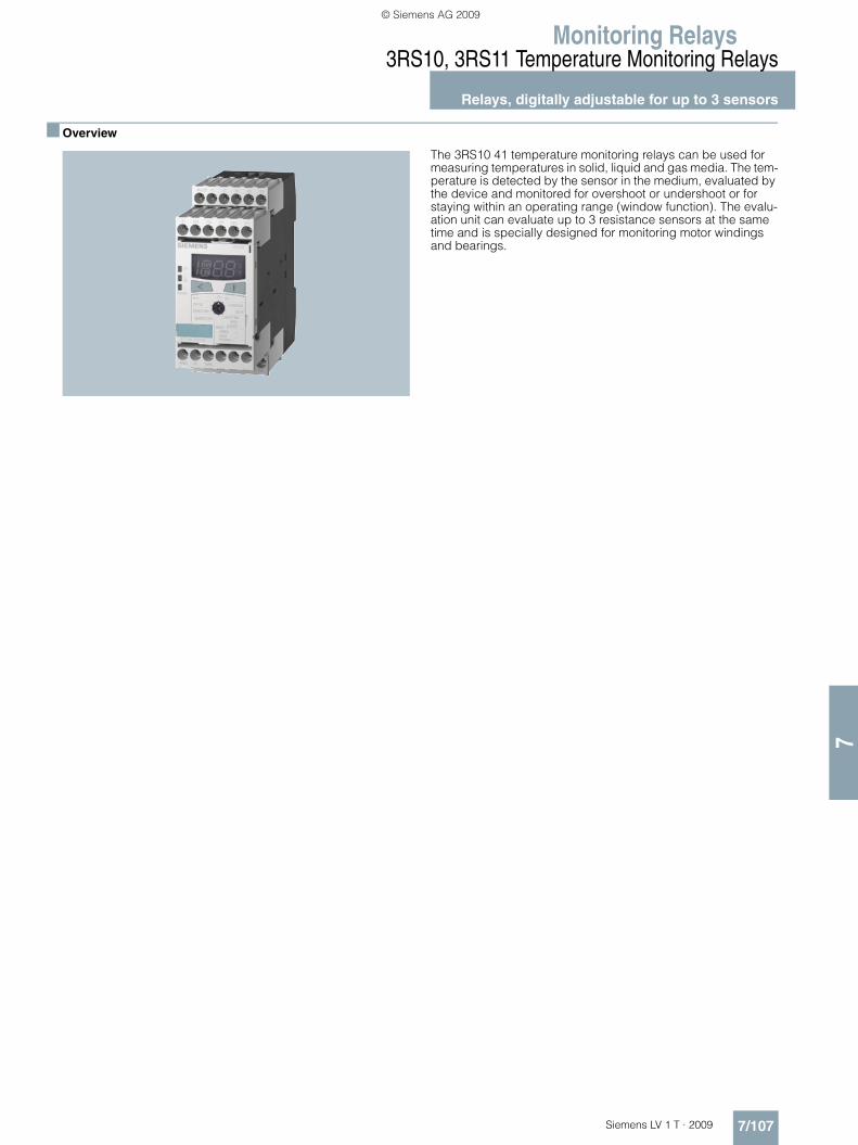
Monitoring Relays
7/107Siemens LV 1 T · 2009
3RS10, 3RS11 Temperature Monitoring Relays
Relays, digitally adjustable for up to 3 sensors
7
■ Overview
The 3RS10 41 temperature monitoring relays can be used for measuring temperatures in solid, liquid and gas media. The tem-perature is detected by the sensor in the medium, evaluated by the device and monitored for overshoot or undershoot or for staying within an operating range (window function). The evalu-ation unit can evaluate up to 3 resistance sensors at the same time and is specially designed for monitoring motor windings and bearings.
LV1T_2009_Gesamtbuch_EN.book Seite 107 Donnerstag, 26. Februar 2009 2:00 14
© Siemens AG 2009
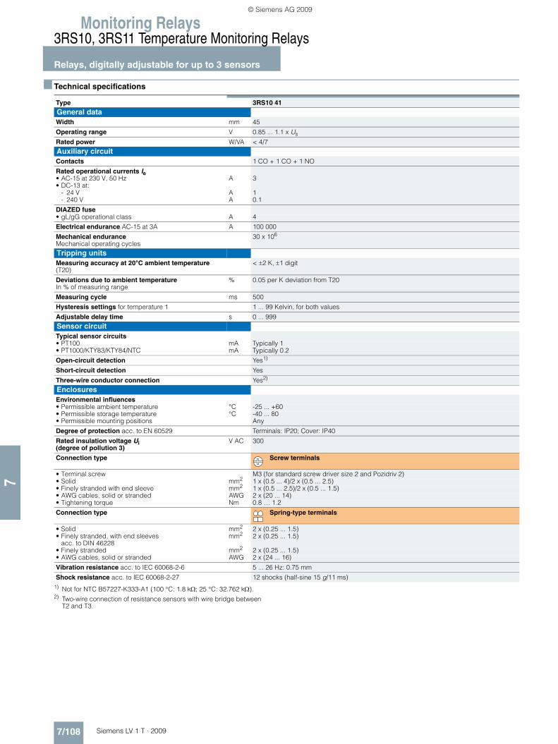
Monitoring Relays3RS10, 3RS11 Temperature Monitoring Relays
Relays, digitally adjustable for up to 3 sensors
7/108 Siemens LV 1 T · 2009
7
■ Technical specifications
1) Not for NTC B57227-K333-A1 (100 °C: 1.8 kΩ; 25 °C: 32.762 kΩ).2) Two-wire connection of resistance sensors with wire bridge between
T2 and T3.
Type 3RS10 41 General dataWidth mm 45
Operating range V 0.85 ... 1.1 x Us
Rated power W/VA < 4/7Auxiliary circuitContacts 1 CO + 1 CO + 1 NO
Rated operational currents Ie • AC-15 at 230 V, 50 Hz A 3• DC-13 at:
- 24 V A 1- 240 V A 0.1
DIAZED fuse • gL/gG operational class A 4
Electrical endurance AC-15 at 3A A 100 000
Mechanical endurance Mechanical operating cycles
30 x 106
Tripping units Measuring accuracy at 20°C ambient temperature (T20)
< ±2 K, ±1 digit
Deviations due to ambient temperature In % of measuring range
% 0.05 per K deviation from T20
Measuring cycle ms 500
Hysteresis settings for temperature 1 1 ... 99 Kelvin, for both values
Adjustable delay time s 0 ... 999Sensor circuit Typical sensor circuits • PT100 mA Typically 1• PT1000/KTY83/KTY84/NTC mA Typically 0.2
Open-circuit detection Yes1)
Short-circuit detection Yes
Three-wire conductor connection Yes2)
EnclosuresEnvironmental influences • Permissible ambient temperature °C -25 ... +60• Permissible storage temperature °C -40 ... 80• Permissible mounting positions Any
Degree of protection acc. to EN 60529 Terminals: IP20; Cover: IP40
Rated insulation voltage Ui (degree of pollution 3)
V AC 300
Connection type Screw terminals
• Terminal screw M3 (for standard screw driver size 2 and Pozidriv 2)• Solid mm2 1 x (0.5 ... 4)/2 x (0.5 ... 2.5)• Finely stranded with end sleeve mm2 1 x (0.5 ... 2.5)/2 x (0.5 ... 1.5)• AWG cables, solid or stranded AWG 2 x (20 ... 14)• Tightening torque Nm 0.8 … 1.2
Connection type Spring-type terminals
• Solid mm2 2 x (0.25 ... 1.5)• Finely stranded, with end sleeves
acc. to DIN 46228mm2 2 x (0.25 ... 1.5)
• Finely stranded mm2 2 x (0.25 ... 1.5)• AWG cables, solid or stranded AWG 2 x (24 ... 16)
Vibration resistance acc. to IEC 60068-2-6 5 ... 26 Hz: 0.75 mm
Shock resistance acc. to IEC 60068-2-27 12 shocks (half-sine 15 g/11 ms)
LV1T_2009_Gesamtbuch_EN.book Seite 108 Donnerstag, 26. Februar 2009 2:00 14
© Siemens AG 2009

Monitoring Relays
7/109Siemens LV 1 T · 2009
3RS10, 3RS11 Temperature Monitoring Relays
Relays, digitally adjustable for up to 3 sensors
7
■ Dimensional drawings
■ Schematics
Circuit example
General item codes
A1, A2, A3 terminals for rated control supply voltage
K1, K2, K3 output relay
Item codes for 3RS10 41
ϑ1 = LED: "Relay 1 tripped"
ϑ2 = LED: "Relay 2 tripped"
Ready = LED: "Device is ready for operation"
1T1 to 1T3 = Sensor connection for resistance sensor 1
2T1 to 2T3 = Sensor connection for resistance sensor 2
3T1 to 3T3 = Sensor connection for resistance sensor 3
Y1/Y2 connection for memory jumper
Caution!
When resistance sensors with two-wire connection are used, T2 and T3 must be jumpered.
NSB0_01412c
45 6586
36574
68 A C92
1)
102
3RS10, 3RS11, 3RS20, 3RS21 digital
CA
10683
10884
1) For standard mounting rail according to EN 60715.
Screw-type terminal
Spring-loaded terminal
Removable terminal
Type
A2NSB0_01338c
A1
K1 15
1618
K2 25
28
K3 33
34
26
Y2Y1
1T11T21T32T12T22T33T13T23T3
Memory
Ready
1
2
LV1T_2009_Gesamtbuch_EN.book Seite 109 Donnerstag, 26. Februar 2009 2:00 14
© Siemens AG 2009

Monitoring Relays3RN1 Thermistor Motor Protection
For PTC sensors
7/110 Siemens LV 1 T · 2009
7
■ Overview
Thermistor motor protection devices are used for direct monitor-ing of the motor winding temperature. For this purpose, the mo-tors are equipped with temperature-dependent resistors (PTC) that are directly installed in the motor winding and abruptly change their resistance at their limit temperature.
■ Design
The 3RN1 tripping units are suitable for use in any climate and finger-safe according to EN 50274. They comply with:• EN 60947-8• EN 61000-6-2 and EN 61000-6-4, "Electromagnetic compati-
bility of I&C equipment in industrial process engineering"
The terminals of the auxiliary contacts are designated in accor-dance with EN 50005.
The 3RN1 tripping units are suitable for snap-on mounting onto TH 35 standard mounting rails according to EN 60715 or for screw fixing using an adapter (Accessories).
Any mounting position is possible.
For devices with the "Manual RESET" function, the test function can be activated and a trip simulated by pressing the blue Test/RESET button for longer than 2 seconds.
If a Type A temperature sensor is connected to a Type A tripping unit, compliance with the operating temperatures is assured (on pick-up and reset) according to IEC 60034-11-2 and EN 60947-8.
The characteristic curves of the Type A temperature sensors are described in EN 60947-8, DIN 44081 and DIN 44082.
Use in areas subject to explosion hazard for gases
All devices are approved for Equipment Group II, Category (2) in Area "G" (areas that contain explosive gases, vapor, spray and air mixtures).
With PTB 01 ATEX 3218 ex II (2) G, compliance with 94/9 EC di-rective Appendix II is confirmed. The safety devices must be se-lected with suitable settings for the safe operation of motors of the "Increased safety" (EEx e) and "Flameproof enclosure" (EEx d) types of protection and are used outside the area sub-ject to explosion hazard.
PTB 01 ATEX 3218 ex II (2) G
The increased danger in areas subject to explosion hazard de-mands careful analysis of the operating manual, the safety and commissioning instructions and the standard (EN 60079-14) for electronic equipment in areas subject to gas explosion hazards.
A risk analysis must be performed for the complete plant or ma-chine. If this risk analysis results in a minimal potential for danger (Safety Category 1), all 3RN1 TMS tripping units can be imple-mented taking into account the safety notes. In the case of plants or machines with a high potential risk, versions with inte-grated short-circuit detection in the sensor circuit are necessary.
Use in areas subject to explosion hazard for dust
PTB 01 ATEX 3218 ex II (2) GD
3RN10 11-.B/-.G, 3RN10 12-.B/-.G and 3RN10 13-...0 tripping units can be used as protective devices for motors in areas sub-ject to gas explosion hazard for protection against impermissible overheating due to overload. If the ATEX marking has the exten-sion "D:=Dust", these units can also be used as protective de-vices for motors in areas subject to dust explosion hazard (EN 50281-1-1).
Additional information is provided in the EC type test certificate which can be obtained from the Internet. The units comply with the requirements of the following classes:
4000
1330
550
250
20
-20°C 0 TNF-20TNF-5
TNF TNF+15 T
R
NSB00320
TNF+5 Device Class
3RN10 00, 3RN10 10, 3RN10 11-.C, 3RN10 12-.C, 3RN10 22, 3RN10 62
EN 954-1: Category 1
3RN10 11-.B, 3RN10 11-.G, 3RN10 12-.B, 3RN10 12-.G, 3RN10 13
EN 954-1: Category 2
LV1T_2009_Gesamtbuch_EN.book Seite 110 Donnerstag, 26. Februar 2009 2:00 14
© Siemens AG 2009

Monitoring Relays
7/111Siemens LV 1 T · 2009
3RN1 Thermistor Motor Protection
For PTC sensors
7
The measuring circuit leads must be routed as separate control cables. It is not permitted to use cores from the supply line of the motor or any other main supply cables. If extreme inductive or capacitive interference is expected as a result of power lines routed in parallel, shielded control cables must be used.
Cable routing
Maximum cable length for sensor circuit cables
1) A short-circuit in the sensor circuit will be detected up to this maximum cable length.
Notes:
Tripping of the thermistor motor protection relay even in combi-nation with a converter must directly result in disconnection. This must be implemented with circuitry.
Mounting and installation must only be performed by qualified personnel who observe the applicable regulations! For mount-ing, use mounting instruction No.: 3ZX1012-0RN10-1AA1.
The 3RN10 is not intended for installation in hazardous areas. For installation in areas subject to explosion hazards, the 3RN10 must be enclosed in a flameproof casing.
For tripping units with a 24 V AC/DC control voltage, electrical separation must be secured with a battery network or a safety transformer according to DIN VDE 0551.
When tripping units with Auto-RESET function are used, a reset is performed automatically after the cooling time has expired. It must be ensured by means of an external interlock (latching with a separate ON and OFF button) that the machine to be moni-tored does not start up again spontaneously.
Units with the "Auto-RESET" function must not be used in appli-cations in which the unexpected restart can lead to personal in-jury or property damage.
In the case of tripping units without short-circuit detection, dur-ing commissioning or after modifications or maintenance work (assembly, disassembly) on the equipment, the sensor resis-tance must be measured using a suitable measuring device. For resistances of < 50 Ω the sensor circuit must be checked for a short-circuit.
If 3RN10 00 units are used to protect EEx e motors, separate monitoring of the control voltage is recommended because there is no Ready LED to indicate connection to the supply voltage.
If 3RN10 13-.BW01 units are used to protect EEx e motors, sep-arate monitoring of the control voltage is recommended be-cause the switching state of the auxiliary contacts does not change if the control voltage fails (use of a bistable relay is recommended).
Before commissioning, the effectiveness of the protection func-tion must be checked.
■ Function
The 3RN1 tripping units operate in accordance with the closed-circuit principle and therefore monitor themselves for open cir-cuit (except: warning output in the case of 3RN10 22). A momen-tary voltage failure of less than 50 ms does not change the status of the auxiliary contacts. The 3RN10 11, 3RN10 12 and 3RN10 13 units with 2 changeover contacts are also equipped with short-circuit detection in the sensor circuit. The unit will trip in the event of a short-circuit in the sensor circuit (resistance in sensor circuit < 20 Ω).
All tripping units (except for 24 V AC/DC ) feature electrical separation between the control circuit and the sensor circuit.
3RN10 00 compact tripping units
The compact tripping unit is equipped with a red LED (TRIPPED) for the tripped indicator and a changeover contact.
After the unit has tripped, it is automatically reset once the ther-mistors have cooled down. The root of the changeover contact is connected to the control voltage (95 is connected to terminal A1).
This unit is particularly suitable in circuits in which the control cir-cuit and signaling circuit have the same potential, e. g. in local control cabinets.
3RN10 10, 3RN10 11, 3RN10 12, 3RN10 13 standard tripping units
The standard devices are equipped with two LEDs (READY and TRIPPED) for an operating and tripped display and are available with either 1 NO + 1 NC or with 2 CO contacts. They are available depending on the version with automatic RESET (3RN10 10), manual/remote RESET (3RN10 11) or manual/automatic and re-mote RESET (3RN10 12 and 3RN10 13). Remote RESET can be achieved by connecting an external pushbutton with a normally-open function to terminals Y1 and Y2. If terminals Y1 and Y2 are bridged, tripping will be followed by an automatic RESET.
The 3RN10 11, 3RN10 12 and 3RN10 13 units with 2 COs also have short-circuit monitoring in the sensor circuit.
The 3RN10 12 and the 3RN10 13 are non-volatile. This means that even if the control supply voltage fails, a trip preceding it will be latched.
In the case of the 3RN10 13 tripping unit, tripping due to a short-circuit in the sensor circuit will be indicated by a flashing red LED. The monostable version also indicates open circuit in the sensor circuit by flashing of the red LED.
3RN10 22 "Warning and disconnection" tripping units
Two sensor circuits can be connected to one 3RN10 22 tripping unit that acts on one output relay with 1 NO contact for warning and 1 CO for disconnection. Temperature sensors with different rated response temperatures TNF are used to implement the "Warning" and "Disconnection" functions. When the "Warning" sensor circuit responds, a yellow LED is lit and when the "Disconnection" circuit responds, a red LED is lit.
The sensor circuits have a different reset response and operat-ing behavior:
"Warning" (terminals 2T1, T2) only features automatic RESET and uses the open-circuit principle.
"Disconnection" (terminals 1T1, T2) can be changed from man-ual RESET to automatic RESET by linking terminals Y1 and Y2. Remote RESET is implemented by connecting an external push-button with a normally-open function.
Conductor cross-section
Cable length for tripping unitsWithout short-circuit detection3RN10 00, 3RN10 103RN10 11-.C, 3RN10 12-.C3RN10 22, 3RN10 62
With short-circuit detection1)
3RN10 11-.B/-.G3RN10 12-.B/-.G3RN10 13
mm2 m m
2.5 2 x 2800 2 x 250
1.5 2 x 1500 2 x 150
0.5 2 x 500 2 x 50
LV1T_2009_Gesamtbuch_EN.book Seite 111 Donnerstag, 26. Februar 2009 2:00 14
© Siemens AG 2009

Monitoring Relays3RN1 Thermistor Motor Protection
For PTC sensors
7/112 Siemens LV 1 T · 2009
7
3RN10 62 tripping units for multiple motor protection
Up to 6 sensor circuits can be connected to the 3RN10 62 trip-ping unit, all of which act on one output relay. The simultaneous protection of several motors (up to 6) is an advantage for multi-motor drives (e. g. if one motor is overloaded, all the other mo-tors of the drive will be shut down). Apart from the red LED "TRIPPED", which signals the switching state of the tripping unit, a LED is assigned to each sensor circuit which indicates the sen-sor circuit that has responded. Unused sensor circuits must be short-circuited.
The reset response of the 3RN10 62 tripping units can be changed from manual RESET to automatic RESET by linking ter-minals Y1 and Y2. Remote RESET is implemented by connecting an external pushbutton with a normally-open function.
Response of the tripping units in the event of control voltage failure
Protective separation
All circuits (outputs, control circuits, sensor and RESET circuits) of the 3RN10 13-1BW10 and 3RN10 13-1GW10 multifunction tripping units (wide voltage range, monostable output relay and screw connection) are safely separated from each other up to a rated voltage of 300 V according to DIN VDE 0100-410 (IEC 60364-4-41) and EN 60947-1.
Function diagrams
3RN10 00/3RN10 10 (Auto-RESET)
1) For versions with 2 CO and short-circuit detection in the sensor circuit see function diagram 3RN10 13.
3RN10 111)
3RN10 13-...01
3RN10 121)/3RN10 22/3RN10 62
3RN10 13-....0
3RN10 22 only
Behavior Monostable Non-volatile, monostable
Bistable
3RN10 003RN10 103RN10 11
3RN10 123RN10 13-....03RN10 223RN10 62
3RN10 13-...01
In case of failure of the control voltage
Device trips Device trips No change in switching state of the auxiliarycontacts
In case of return of the control volt-age without a pre-ceding tripping operation
Device resets Device resets No change in switching state of the auxiliary contacts
In case of return of the control volt-age after a pre-ceding tripping operation
Device resets The device remains tripped
No change in switching state of the auxiliarycontacts
�����
�����
����� ��
�����������
��������
�
� � � � �
� � � � �
� � � � � �
� � � � � � �
� � � �
�
� � � � � � � � � � �
�����
����
���
���
������
�����������
����
�
����������
�����
���
���
������
�����������
��������
� ���
����������
�����
���
���
������
�����������
��������
�
����������
����
�����!��"
���������#���������
��
LV1T_2009_Gesamtbuch_EN.book Seite 112 Donnerstag, 26. Februar 2009 2:00 14
© Siemens AG 2009

Monitoring Relays
7/113Siemens LV 1 T · 2009
3RN1 Thermistor Motor Protection
For PTC sensors
7
■ Technical specifications
1) See Catalog LV 1, Selection and ordering data.2) Remote RESET possible by disconnecting control voltage.3) Open circuits are only indicated by monostable versions
(3RN10 13-....0).
Type Compact units
Standard devices Multi-function units
Warning + tripping
Multiple motor protection
3RN10 00 3RN10 10 3RN10 11 3RN10 12 3RN10 13 3RN10 22 3RN10 62General dataWidth mm 22.5 45
Number of connectable sensor circuits
1 2 6
Response in the event of control voltage failure
1)
Manual RESET No Yes
Automatic RESET Yes No Yes
Remote RESET No Yes2) Yes
TEST pushbutton No Yes
Short-circuit detection for sensor circuit
No Yes (for 2 CO units) Yes No
Short-circuit and open-circuit indication
No Yes3) No
Warning and disconnection in one unit
No Yes No
Tripping unitsRated insulation voltage Ui (degree of pollution 3)
V 300
Permissible ambient temperature °C -25 … +60
Permissible storage temperature °C -40 … +80
EMC tests EN 61000-6-2, EN 61000-6-4
Degree of protection acc. to EN 60529
IP20
Connection type Screw terminals
• Terminal screw M3 (for standard screw driver size 2 and Pozidriv 2)• Solid mm2 1 x (0.5 ... 4)/2 x (0.5 ... 2.5)• Finely stranded with end sleeve mm2 1 x (0.5 ... 2.5)/2 x (0.5 ... 1.5)• AWG cables
solid or strandedAWG 2 x (20 ... 14)
• Tightening torque Nm 0.8 … 1.2
Connection type Spring-type terminals
• Solid mm2 2 x (0.25 ... 1.5)• Finely stranded with end sleeves
acc. to DIN 46228mm2 2 x (0.25 ... 1.5)
• Finely stranded mm2 2 x (0.25 ... 1.5)• AWG cables
solid or strandedAWG 2 x (24 ... 16)
Sensor circuit Measuring circuit load at RF ≤ 1.5 mW
≤ 5
Voltage in sensor circuit at RF ≤ 1.5 mW
V ≤ 2
Response temperature (depends on sensor)
°C 60 ... 180
Coupling time (depends on sensor)
s About 5
Summation PTC resistance RF (per sensor loop)
kΩ ≤ 1.5
Response value kΩ 3.4 ... 3.8Return value kΩ 1.5 ... 1.65
Response tolerance °C ±6
LV1T_2009_Gesamtbuch_EN.book Seite 113 Donnerstag, 26. Februar 2009 2:00 14
© Siemens AG 2009

Monitoring Relays3RN1 Thermistor Motor Protection
For PTC sensors
7/114 Siemens LV 1 T · 2009
7
1) See Catalog LV 1, Selection and ordering data.2) In > 1 kA weld-free according to EN 60947-5-1.
■ Dimensional drawings
3RN1 with 1 ... 2 sensor circuits
3RN10 62
Type Compact units
Standard devices Multi-function units
Warning + tripping
Multiple motor protection
3RN10 00 3RN10 10 3RN10 11 3RN10 12 3RN10 13 3RN10 22 3RN10 62Control circuitRated control supply voltage Us 1)
Operating range • 110/230 V AC 0.85 ... 1.1 x Us• 24 ... 240 V AC/DC 0.85 ... 1.1 x Us• 24 V AC/DC 0.85 ...1.2 x Us for DC operation, 0.85 ...1.1 x Us for AC operation
Rated power • AC/DC W < 2
Max. mains buffering time ms 50Auxiliary circuitConventional thermal current Ith A 5
Rated operational current Ie • AC-15 240 V A 3• DC-13 24 V A 1
DIAZED fuse A 62)
CSA and UL rated data, control circuitRated control voltage 50/60 Hz• AC V 300• DC V 300
Switching capacity R 300/B 300
Protective separation up to 300 V acc. to DIN 60947-1
-- 3RN10 13-1BW10, 3RN10 13-1GW10
--
NSB0_01731a
A B C74
86536
62 90
1522,5
62 110
1522,5
82
1)
BA C
9283 102
9484 103
3RN10 00 3RN10 10-.B3RN10 10-.G3RN10 113RN10 123RN10 133RN10 22
3RN10 10-.C
1) For standard mounting rail according to EN 60715.
Screw-type terminal
Spring-loaded terminal
Removable terminal
Type
NSB0_01732a
45 6586
36574
68 A C92
1)
102
10683
10884
3RN10 62
A C
1) For standard mounting rail according to EN 60715.
Typ
Screw-type terminal
Spring-loaded terminal
Removable terminal
Type
LV1T_2009_Gesamtbuch_EN.book Seite 114 Donnerstag, 26. Februar 2009 2:00 14
© Siemens AG 2009

Monitoring Relays
7/115Siemens LV 1 T · 2009
3RN1 Thermistor Motor Protection
For PTC sensors
7
■ Schematics
Circuit diagrams
1) For units with combination voltages 230 V/110 V AC (3RN10 11-.CK00 and 3RN10 12-.CK00) the following applies: A1 and A2: 230 V AC, A3 and A2: 110 V AC.
Illustrated with control voltage applied
Illustrated with control voltage not applied
Illustrated with control voltage applied
Illustrated with control voltage not applied
3RN10 00, 1 CO
3RN10 10, 1 NO + 1 NC 3RN10 10, 2 COs
3RN10 111), 1 NO + 1 NC 3RN10 11, 2 COs
3RN10 121), 1 NO + 1 NC 3RN10 12, 2 COs
3RN10 13-...0 (monostable)
3RN10 13-...1 (bistable)
3RN10 22
3RN10 62
General item codes
A1, A2 , A3
NT/RY1, Y2
⇑
Connections of the control voltageAmplifierTEST/RESET buttonConnections for remote RESET (jum-pered = Auto-RESET)The double arrow indicates an operating state which deviates from the standard repre-sentation of the contact according to DIN 40900, Part 7 (Here: Position of the contacts when control voltage is applied to terminals A1 and A2)
Item codes for 3RN10
H1H2KT1, T2
"READY" LED"TRIPPED" LEDOutput relayConnections of the sensor loop
Item codes for 3RN10 22
H1H2H3K1
K2
1T1 and T22T1 and T2
"READY" LED"TRIPPED" LED"ALARM" LEDOutput relayfor warning threshold ("ALARM" LED)Output relay for discon-nection ("TRIPPED" LED)Connections of the sensor loop
. Important!
Close unconnected sensor circuits.
Item codes for 3RN10 62
H1 to H6
H7H8K1T1, 1T2to6T1, 6T2
LED for the tripped sensor loop"READY" LED"TRIPPED" LEDOutput relayConnections of the 1st sensor loop Connections of the 6th sensor loop
. Important!
Close unconnected sensor circuits.
���#�
� � �� #� #�
�$� �
�%� ���
�����������
�� ���
96 98T1 T2 A2
95 97A1
(14) (22)
(13) (21)
NSB0_00323b
H1
N H2 K
T/R
� �� #� #�
�� #�
� �� ��
��
$� �
�%�
��� ���
��������#�
��� �%� ���
$�
�
96 98T1 T2 A2
95 97A1
(14) (22)
(13) (21)
NSB0_00323b
H1
N H2 K
T/R�
�
�� #� #�
�� #�
� �� ��
��
$� �
�%�
��� ���
��������#�
��� �%� ���
$�
�
#� #�
#� #��� �� �� ���
$�
� $� �
� � ��
�
�%� ���
��� ���
�����������
T1
T/R
A2 96 98
95
T2 06 08
05
H2 K
(14)
(11) (21)
NSB0_01399a
(12) (24) (22)
H1
N
Y1 Y2 A1
�
�
�� #� #�
�� �� �� #�
� �� ��
��
$� �
�%�
��� ���
�������%��
��� �%� ���
$�
�
�
�
�� #� #�
�� �� �� #�
� �� ��
��
$� �
�%�
��� ���
����������
��� �%� ���
$�
�
�� �� �� #�
�� �%� �� �� � �� #� #�
��
$�
�
$�
� $� ��
�
�� ���
�%� ���
����������&
���
� #� #�
#�
�
���� �� ��
�� �� ��
�
$� $�
$�
$%
� �
� �
%� �� �� ����%����� �� #� �%� ���
��� ���
���������#�
LV1T_2009_Gesamtbuch_EN.book Seite 115 Donnerstag, 26. Februar 2009 2:00 14
© Siemens AG 2009

3TK28 Safety Relays
General data
7/116 Siemens LV 1 T · 2009
7
■ Overview
SIRIUS safety relays are the key modules of a consistent and cost-effective safety chain. Be it EMERGENCY-STOP disconnec-tion, protective door monitoring or the protection of presses or punches – with SIRIUS safety relays every safety application can be implemented to optimum effect in terms of engineering and price.
SIRIUS safety relays provide numerous safety-related functions:• Monitoring the safety functions of sensors• Monitoring the sensor cables• Monitoring the correct operation of the safety relay• Monitoring the actuators (contactors) in the shutdown circuit• Safety-oriented disconnection when dangers arise
SIRIUS safety relays meet the highest requirements (Category 4) according to EN 954-1 and achieve the highest safety integrity level (SIL 3) according to IEC 61508.
LV1T_2009_Gesamtbuch_EN.book Seite 116 Donnerstag, 26. Februar 2009 2:00 14
© Siemens AG 2009

3TK28 Safety Relays
7/117Siemens LV 1 T · 2009
General data
7
■ Function
SIRIUS safety relays and the safety chain
A safety chain normally comprises the following functions: sensing, evaluating and shutdown.
SensingThe detection of a safety requirement, e. g. when an EMERGEN-CY-STOP is actuated or someone enters a hazardous area which is protected by sensors such as light arrays or laser scanners.
Evaluating The evaluation of a safety requirement and the reliable initiation of a reaction, e. g. shutting down the enabling circuits.
ShutdownThe shutting down of hazards, e. g. a power supply, using the downstream contactors. SIRIUS safety relays are active in the evaluating and shutdown links of this safety chain.
The inputs of the device (number and type) are portrayed in the sensor interface. The safety logistics is shown at the center. The mode of operation of the device and the way the inputs act on the outputs are explained with the help of this safety logistics. The type and number of enabling circuits or signaling outputs are shown in the actuator interface, and the setting options (pa-rameters) of the device are shown at the lower edge of the graphic.
Notes on the function diagrams on pages 7/118 to 7/143
In the interest of simplicity, the function diagrams show only the inputs and outputs which are required to explain the safety func-tion. The power supply inputs and the sensors and actuators which can be connected to the interfaces are disregarded be-cause they are not relevant for illustrating the function.
The legends explain the meaning of the symbols.
��
������
������
�
��9�1����
��� ������
�����������
��� ������������
� ������������� ����������� �������������
������������� ���������
����������������� ������������������������ ���������������������
��� !�
"���������#
LV1T_2009_Gesamtbuch_EN.book Seite 117 Donnerstag, 26. Februar 2009 2:00 14
© Siemens AG 2009

3TK28 Safety Relays
With electronic enabling circuits
7/118 Siemens LV 1 T · 2009
7
■ Design
The solid-state safety relays can be used in EMERGENCY-STOP devices to EN 418 and in safety circuits to EN 60204-1 (11.98), for example, for moving covers and protective doors. Depend-ing on the device type and the external circuit, the maximum cat-egory that can be achieved is Category 4 of EN 954-1 or SIL 3 according to IEC 61508.
Mounting
For snap-on mounting on 35 mm standard mounting rail accord-ing to EN 60715. Screw fixing is also possible for the devices by means of 2 additional 3RP19 03 push-in lugs.
■ Function
Basic units
3TK28 40
The 3TK28 40 has one sensor input S1 and two solid-state en-abling circuits. If the signal is no longer applied to the sensor in-put, the enabling circuits are disconnected immediately.
3TK28 41 and 3TK28 42
The 3TK28 41 and 3TK28 42 each has one sensor input S1 and one cascading input KAS/BS as well as two solid-state enabling circuits (2 x instantaneous or 1 x instantaneous and 1 x with de-lay). If the signal is no longer applied to either of the two inputs, the enabling circuits are isolated immediately or according to the set delay time. Autostart or monitored start can be selected in the parameterization.
Legend
Sensor interfaceKAS/BS: Cascading input or normal switching duty.
Normal switching duty: Connection of a PLC output for exam-ple. The enabling circuits and hence the connected loads can then be operated by the machine control. The safety function is on a higher level.
Sx: Sensor input
Safety logicAS/ÜS: Automatic or monitored start depending on the parameteri-
zation
Time delay, OFF-delay
ParametersAS/ÜS: Automatic or monitored start depending on the parameteri-
zationQS: With or without crossover monitoring1-/2-channel: One-channel / two-channel sensor connection
Actuator interfaceFKel: Enabling circuit, solid-state (non-floating)NO: NO contactNOtv: NO contact, time-delayed
NS
C0_
0068
6a
S
1
FKel
FK
el
AS/ÜS
AS/ÜS (NO)
(NO)
1-/2-channel
3TK28 40 basic unit
NS
C0_
0068
7
KAS/ BS
S
1
FK
el
FK
el
AS/ÜS
AS/ÜS &
QS
(NO)
(NO)
3TK28 41 basic unit
NS
C0_
0068
8
KAS/ BS
S
1
FK
el
FK
el
AS/ÜS
AS/ÜS &
QS
tv
(NO)
(NO tv)
3TK28 42 basic unit
tv
LV1T_2009_Gesamtbuch_EN.book Seite 118 Donnerstag, 26. Februar 2009 2:00 14
© Siemens AG 2009

3TK28 Safety Relays
7/119Siemens LV 1 T · 2009
With electronic enabling circuits
7
Multi-function units
3TK28 45-.HB.. "Monitored start and autostart"
The 3TK28 45-.HB.. has two sensor inputs (S1 with monitored start, S2 with autostart), a cascading input (KAS/BS with au-tostart) and a changeover input (key-operated switch). On the output side are two relay enabling circuits, two solid-state en-abling circuits and a solid-state signaling output.
Normal operationIn normal operation (key-operated switch "OFF"), all enabling cir-cuits are activated. All inputs are "AND"-interconnected and act simultaneously on all enabling circuits, some time-delayed.
Legend
Sensor interfaceKAS/BS: Cascading input or normal switching duty.
Normal switching duty: Connection of a PLC output for example. The enabling circuits and hence the connected loads can then be operated by the machine control. The safety function is on a higher level.
Sx: Sensor inputKey-operatedswitch: Bridging of the sensor connected to S2
(normal/service operation)
Safety logicAS: Automatic start. Device starts automatically once the
enabling conditions are fulfilled. If a START button is integrated in the feedback circuit, a manual start is also possible (up to Category 3 according to EN 954-1).
ÜS: Monitored start. Device does not start until after the enabling conditions are fulfilled and a start signal is issued.
Time delay, OFF-delay
Service operationIn service operation (key-operated switch "ON"), only two of the four enabling circuits are activated. In this case the sensor input S2 (e. g. protective door) has no function. The hazard area can be entered because the hazardous movement is switched off by means of the two inactive enabling circuits. The sensor input S1 and the cascading input KAS/BS still act on the active enabling circuits.
ParametersQS: With or without crossover monitoring
Actuator interfaceFKel: Enabling circuit, solid-state (non-floating)FKrel: Enabling circuit, relay contact (floating)MKel: Signaling circuit, solid-state (non-floating)NO: NO contactNOtv: NO contact, time-delayed
NS
C0_
0069
7
KAS/BS
S1
FKrel
FKel
FKrel
FKel
MKel
S2
ÜS
AS
&
QS S1 QS S2
AS
3TK28 45 "Automatic and monitored start" instantaneous (normal operation)
Key-oper.switch
OFF
(NO)
(NO)
(NO)
(NO)
(NO)
NS
C0_
0069
9
KAS/ BS S
1
FK
rel
FK
el
FK
rel
FK
el
MK
el
S
2
ÜS
AS
&
QS S
1
QS S
2
AS
tv
tv
3TK28 45 "Automatic and monitored start" delayed (normal operation)
Key-oper.switch
OFF
(NO)
(NO)
(NO )
(NO )
(NO)
tv
tv
tv
NS
C0_
0069
8
KAS/ BS S
1
FK
r el
FK
el
FK
rel
FK
el
MK
el
S
2
ÜS
&
QS S 1
QS S 2
AS
3TK28 45 "Automatic and monitored start" instantaneous (service operation)
Key-oper.switchON
(NO)
(NO)
(NO)
(NO)
(NO)
NS
C0_
0070
0
KAS/ BS S
1
FK
rel
FK
el
FK
rel
FK
el
MK
el
S
2
ÜS
&
QS S
1
QS S
2
AS
tv
3TK28 45 "Automatic and monitored start" delayed (service operation)
Key-oper.switch
ON
(NO)
(NO)
(NO )
(NO )
(NO)
tv
tv
LV1T_2009_Gesamtbuch_EN.book Seite 119 Donnerstag, 26. Februar 2009 2:00 14
© Siemens AG 2009

3TK28 Safety Relays
With electronic enabling circuits
7/120 Siemens LV 1 T · 2009
7
3TK28 45-.DB.. "Monitored start"
The 3TK28 45-.DB.. has two sensor inputs (S1, S2 with monitored start), a cascading input (KAS/BS with autostart) and a changeover input (key-operated switch). On the output side are two relay enabling circuits, two solid-state enabling circuits and a solid-state signaling output.
Normal operation In normal operation (key-operated switch "OFF"), all enabling cir-cuits are activated. All inputs are "AND"-interconnected and act simultaneously on all enabling circuits, some time-delayed.
Legend
Sensor interfaceKAS/BS: Cascading input or normal switching duty.
Normal switching duty: Connection of a PLC output for example. The enabling circuits and hence the connected loads can then be operated by the machine control. The safety function is on a higher level.
Sx: Sensor inputKey-operatedswitch: Bridging of the sensor connected to S2
(normal/service operation)
Safety logicAS: Automatic start. Device starts automatically once the
enabling conditions are fulfilled. If a START button is integrated in the feedback circuit, a manual start is also possible (up to Category 3 according to EN 954-1).
ÜS: Monitored start. Device does not start until after the enabling conditions are fulfilled and a start signal is issued.
Time delay, OFF-delay
Service operation In service operation (key-operated switch "ON"), only two of the four enabling circuits are activated. In this case the sensor input S2 (e. g. protective door) has no function. The hazard area can be entered because the hazardous movement is switched off by means of the two inactive enabling circuits. The sensor input S1 and the cascading input KAS/BS still act on the active enabling circuits.
ParametersQS: With or without crossover monitoring
Actuator interfaceFKel: Enabling circuit, solid-state (non-floating)FKrel: Enabling circuit, relay contact (floating)MKel: Signaling circuit, solid-state (non-floating)NO: NO contactNOtv: NO contact, time-delayed
NS
C0_
0070
1
KAS/ BS S
1
FK
rel
FK
el
FK
rel
FK
el
MK
el
S
2
ÜS
ÜS
&
QS S 1 QS S 2
AS
3TK28 45 "Monitored start" instantaneous (normal operation)
Key-oper.switch
OFF
(NO)
(NO)
(NO)
(NO)
(NO)
NSC
0_00
703
KAS/ BS S
1
FK
rel
FK
el
FK
rel
FK
el
MK
el
S
2
ÜS
ÜS
&
QS S 1 QS S 2
AS
tv
tv
3TK28 45 "Monitored start" delayed (normal operation)
Key-oper.switch
OFF
(NO)
(NO)
(NO )
(NO )
(NO)
tv
tv
tv
NS
C0_
0070
2
KAS/ BS S
1
FK
r el
FK
el
FK
rel
FK
el
MK
el
S
2
ÜS
&
QS S 1 QS S 2
AS
3TK28 45 "Automatic and monitored start" instantaneous (service operation)
Key-oper.switchON
(NO)
(NO)
(NO)
(NO)
(NO)
NSC
0_00
704
KAS/ BS S
1
FK
rel
FK
el
FK
rel
FK
el
MK
el
S
2
ÜS
&
QS S 1 QS S 2
AS
tv
3TK28 45 "Monitored start" delayed (service operation)
Key-oper.switch
ON
(NO)
(NO)
(NO )
(NO )
(NO)
tv
tv
LV1T_2009_Gesamtbuch_EN.book Seite 120 Donnerstag, 26. Februar 2009 2:00 14
© Siemens AG 2009

3TK28 Safety Relays
7/121Siemens LV 1 T · 2009
With electronic enabling circuits
7
3TK28 45-.EB.. "OK button"
The 3TK28 45-.EB.. has two sensor inputs (S1 OK button with au-tostart, S2 protective door with selectable monitored start or au-tomatic start), a cascading input (KAS/BS with autostart) and a changeover input (key-operated switch). On the output side are two relay enabling circuits, two solid-state enabling circuits and a solid-state signaling output.
Normal operation In normal operation (key-operated switch "OFF"), all enabling cir-cuits are activated. The cascading input KAS/BS and the protec-tive door input S2 are "AND"-interconnected and act simultaneously on all enabling circuits, some time-delayed. The input S1 for the OK button has no function here. Opening the pro-tective door or a missing signal at the cascading input KAS/BS will deactivate all enabling circuits.
Legend
Sensor interfaceKAS/BS: Cascading input or normal switching duty.
Normal switching duty: Connection of a PLC output for example. The enabling circuits and hence the connected loads can then be operated by the machine control. The safety function is on a higher level.
Sx: Sensor inputKey-operatedswitch: Bridging of the sensor connected to S2
(normal/service operation)
Safety logicAS: Automatic start. Device starts automatically once the
enabling conditions are fulfilled. If a START button is integrated in the feedback circuit, a manual start is also possible (up to Category 3 according to EN 954-1).
AS/ÜS: Automatic or monitored start depending on the parameterization
Time delay, OFF-delay
Service operationIn service operation (key-operated switch "ON"), only two of the four enabling circuits are activated. In this case the sensor input S2 (e. g. protective door) has no function. The hazard area can be entered because the hazardous movement is switched off by means of the two inactive enabling circuits. Using the OK button at sensor input S1, the hazardous movement can be started in spite of an open protective door.
ParametersQS: With or without crossover monitoringAS/ÜS: Automatic or monitored start depending on the parameterization
Actuator interfaceFKel: Enabling circuit, solid-state (non-floating)FKrel: Enabling circuit, relay contact (floating)MKel: Signaling circuit, solid-state (non-floating)NO: NO contact
NS
C0_
0070
5
KAS/ BS S
1
FK
rel
FK
el
FK
rel
FK
el
MK
el
S 2 AS/ÜS
&
QS S 1 QS S AS/ÜS 2
AS
3TK28 45 "Acknowledgement button" instantaneous (normal operation)
OFF
Key-oper.switch
Protectivedoor
Ackowl.button
(NO)
(NO)
(NO)
(NO)
(NO)
NS
C0_
0070
7
KAS/ BS S 1
FK
rel
FK
el
FK
rel
FK
el
MK
el
S 2 AS/ÜS
&
QS S 1 QS S AS/ÜS 2
AS
tv
tv
3TK28 45 "Acknowledgement button" delayed (normal operation)
(NO)
(NO)
(NO)
(NO)
(NO)
Key-oper.switch
Protectivedoor
Acknowl.button
OFF
tv
NS
C0_
0070
6
KAS/ BS S
1
FK
rel
FK
el
FK
rel
FK
el
MK
el
S 2
AS
&
QS S 1 QS S AS/ÜS 2
AS
3TK28 45 "Acknowledgement button" instantaneous (service operation)
ON
Key-oper.switch
Protectivedoor
Acknowl.button
(NO)
(NO)
(NO)
(NO)
(NO)
NS
C0_
0070
8
KAS/ BS S
1
FK
rel
FK
el
FK
rel
FK
el
MK
el
S 2
AS
QS S 1 QS S AS/ÜS 2
AS
&
tv
tv
3TK28 45 "Acknowledgement button" delayed (service operation)
(NO)
(NO)
(NO)
(NO)
(NO)
Key-oper.switch
Acknowl.button
Protectivedoor
ON
LV1T_2009_Gesamtbuch_EN.book Seite 121 Donnerstag, 26. Februar 2009 2:00 14
© Siemens AG 2009

3TK28 Safety Relays
With electronic enabling circuits
7/122 Siemens LV 1 T · 2009
7
3TK28 45-.FB.. "Spring-type interlocking"
The 3TK28 45-.FB.. has two sensor inputs (S1: EMERGENCY-STOP with monitored start, S2: protective door with interlock and monitored start), a cascading input (KAS/BS with autostart) and a door-enabling input. On the output side are a relay enabling circuit, two solid-state enabling circuits, a relay solenoid control output and a solid-state signaling output.
Not enabled If the protective door is not enabled, it cannot be opened. If the signal is no longer applied to the inputs S1 or KAS/BS, the en-abling circuit is deactivated.
EnabledWith a signal at the door enabling input, the solenoid control out-put and the second solid-state enabling circuit are activated af-ter the delay time has elapsed. The protective door is thus enabled.
Legend
Sensor interfaceKAS/BS: Cascading input or normal switching duty.
Normal switching duty: Connection of a PLC output for example. The enabling circuits and hence the connected loads can then be operated by the machine control. The safety function is on a higher level.
Sx: Sensor inputDoor enabling: Isolating the lock on the protective door
Safety logicAS: Automatic start. Device starts automatically once the
enabling conditions are fulfilled. If a START button is integrated in the feedback circuit, a manual start is also possible (up to Category 3 according to EN 954-1).
ÜS: Monitored start. Device does not start until after the enabling conditions are fulfilled and a start signal is issued.
Time delay, OFF-delay
Time delay, ON-delay
3TK28 45-.GB.. "Solenoid interlocking"
The 3TK28 45-.GB.. has two sensor inputs (S1: EMERGENCY-STOP with monitored start, S2: protective door with interlock and monitored start), a cascading input (KAS/BS with autostart) and a door-enabling input. On the output side are a relay enabling circuit, two solid-state enabling circuits, a relay solenoid control output and a solid-state signaling output.
Not enabled If the protective door is not enabled, it cannot be opened. If the signal is no longer applied to the inputs S1 or KAS/BS, the en-abling circuit is deactivated.
Enabled With a signal at the door enabling input, the solenoid control out-put and the second solid-state enabling circuit are deactivated after the delay time has elapsed. The protective door is thus en-abled.
ParametersQS: With or without crossover monitoring
Actuator interfaceFKel: Enabling circuit, solid-state (non-floating)FKrel: Enabling circuit, relay contact (floating)MKel: Signaling circuit, solid-state (non-floating)NO: NO contact
NS
C0_
0070
9
KAS/BS
S1
FKrel
FKel
FKrel
FKel
MKel
S2
ÜS
ÜS
&
QS S1 QS S2
AS
Enablingof door
Protectivedoor withtumbler
Solenoidcontrol
EMER-GENCY-STOP
3TK28 45 "Spring-type interlock" not enabled
(NO)
(NO)
(NO)
(NO)
NS
C0_
0071
0
KAS/BS
S1
FKrel
FKel
FKrel
FKel
MKel
S2
QS S1 QS S2
tv
tvEnablingof door
Protectivedoor withtumbler
Solenoidcontrol
EMER-GENCY-STOP
3TK28 45 "Spring-type interlock" enabled
(NO)
(NO)
(NO)
(NO)
tv
tv
NS
C0_
0071
1a
KAS/BS
S1
FKrel
FKel
FKrel
FKel
MKel
S2
ÜS
ÜS
&
QS S1 QS S2
AS
Enablingof door
Protectivedoor withtumbler
Solenoidcontrol
EMER-GENCY-STOP
3TK28 45 "Solenoid interlock" not enabled
(NO)
(NO)
(NO)
(NO)
NS
C0_
0071
2a
KAS/BS
S1
FKrel
FKel
FKrel
FKel
MKel
S2
QS S1 QS S2
tv
tvEnablingof door
Protectivedoor withtumbler
Solenoidcontrol
EMER-GENCY-STOP
3TK28 45 "Solenoid interlock" enabled
(NO)
(NO)
(NO)
(NO)
LV1T_2009_Gesamtbuch_EN.book Seite 122 Donnerstag, 26. Februar 2009 2:00 14
© Siemens AG 2009

3TK28 Safety Relays
7/123Siemens LV 1 T · 2009
With electronic enabling circuits
7
■ Technical specifications
Type 3TK28 40 3TK28 41 3TK28 42 3TK28 45-..B40 3TK28 45-..B413TK28 45-..B423TK28 45-..B44
General dataStandards EN 60204-1,
EN ISO 12100, EN 954-1, IEC 61508
EN 60204-1, EN ISO 12100, EN 954-1, IEC 61508 EN 50156-1
EN 60204-1, EN ISO 12100, EN 954-1, IEC 61508
Test certificates TÜV, UL, CSA
Safety-oriented output contacts• Instantaneous FKrel -- 2 1• Time-delayed FKrel (tv) -- -- 1
Safety-oriented semiconductor outputs• Instantaneous FKel 2 1 2 1• Time-delay FKel (tv) -- 1 -- 1
Signaling contacts MKrel --
Semiconductor signaling outputs MKrel -- 1
Sensor inputs S 1 2
Cascading inputs KAS/BS -- 1
Degree of protection acc. to EN 60529• Enclosure IP40• Terminals IP20
Shock resistance sine wave g/ms 8/10 and 15/5
Permissible mounting positions Any
Touch protection acc. to EN 61140 or EN 60900
Finger-safe
Height mm 102: Screw terminals; 104: Spring-type terminals
Width mm 22.5 45
Depth mm 86 120
Weight kg 0.180 0.400
Connection type Screw terminals
• Terminal screw M 3 (standard screwdriver, size 2 and Pozidriv 2)• Solid mm2 1 x (0.5 ... 4)/2 x (0.5 ... 2.5)• Finely stranded with end sleeve mm2 1 x (0.5 ... 2.5)/2 x (0.5 ... 1.5)• AWG cables, solid or stranded AWG 2 x (24 ... 16)• Tightening torque Nm 0.8 … 1.2
Connection type Spring-type terminals
• Solid mm2 2 x (0.25 ... 1.5)• Finely stranded, with end sleeves acc. to
DIN 46228mm2 2 x (0.25 ... 1.5)
• Finely stranded mm2 2 x (0.25 ... 1.5)
Electrical specificationsRated control supply voltage Us V 24 DC
Operating rangeDC operation V 0.9 ... 1.15 × Us 0.85 ... 1.15 × Us
Rated insulation voltage Ui• For control circuit V 50 50• For outputs V 50 50/300
Rated impulse withstand voltage Uimp• For control circuit V 500 500• For outputs V 500 500/4000
Rated power at Us W 1.5 1.3 2.5
Frequency ranges Hz --
Rated operational current Ie (relay outputs) at• AC-15 at 115 V A -- --• AC-15 at 230 V A -- 3• DC-13 at 24 V A -- 1• DC-13 at 115 V A -- --• DC-13 at 230 V A -- 0.1
Rated operational current Ie (semiconductor outputs) at• DC-13 at 115 V A 0.5 1.5 0.5• DC-13 at 230 V A -- -- --
Electrical endurance Operat-ing cycles
Unlimited
Mechanical endurance Operat-ing cycles
-- 105
Switching frequency z 1/h 2000
LV1T_2009_Gesamtbuch_EN.book Seite 123 Donnerstag, 26. Februar 2009 2:00 14
© Siemens AG 2009

3TK28 Safety Relays
With electronic enabling circuits
7/124 Siemens LV 1 T · 2009
7
■ Technical specifications
Type 3TK28 40 3TK28 41 3TK28 42 3TK28 45-..B40 3TK28 45-..B413TK28 45-..B423TK28 45-..B44
Electrical specifications (continued)Conventional thermal current Ith --
Conventional thermal current Ith• 1 contact A --• 2 contacts A --• 3 contacts A --• 4 contacts A --
Fusing for output contactsFuse links LV HRC Type 3NA, DIAZED Type 5SB, NEOZED Type 5SE, gL/gG operational class• gL/gG Not required• Quick Not required
Maximum line resistance Ω 250 1000
Cable length from terminal to terminalWith Cu 1.5 mm2 and 150 nF/km
m 2000 1000
TimesBridging of voltage dips, supply voltage (only internal, no outputs) (only internal, no outputs)
ms 25
Make-time tE• For automatic start typ. ms 80 60 60• For automatic start max. ms 100 100 100• For automatic start after mains failure typ. ms 350 6000 --• For automatic start after mains failure max. ms 500 7000 --• For monitored start typ. ms 60 60 60• For monitored start max. ms 100 100 100
Release time tR• For sensor typ. ms 20 45 -- 45 --• For sensor max. ms 30 60 0.05 ... 300
Adjustable-- 0.05 ... 300
Adjustable• For mains failure typ. ms 0 0 0 25 25• For mains failure max. ms 0 0 0 30 30
Recovery time tW• After sensor ms 120 400 400• After mains failure s 0.5 Max. 7 Max. 8
Minimum command duration tB• Sensor input ms 5 45• ON button input ms 60 200 ... 5000• Cascading input ms 5 45
Simultaneity tG ms ∞
TemperaturesPermissible ambient temperature
• During operation °C –25 ... +60• During storage °C –40 ... +80
Safety specificationsSafety integrity level SIL CLacc. to IEC 61508
2 3
Performance level PLacc. to ISO 13849-1
-- e
Safety category CATacc. to EN 954-1
3 4
Typeacc. to EN 574
--
Probability of a dangerous failure• Per hour (PFHD) 1/h 1.05 x 10⁻⁸ 5.36 x 10⁻¹¹ 6.86 x 10⁻⁹
• On demand (PFD) -- -- --
Proof-test interval T1 a 10 20
Environmental dataEMC EN 60947-5-1,
EN 61000-6-2, EN 61000-6-4
IEC 60947-5-1, IEC 60000-4-3, IEC 60000-4-5, IEC 60000-4-6
Vibrationsacc. to EN 60068-2-6• Frequency Hz 5 ... 500• Amplitude mm 0.075
Climatic withstand capability EN 60068-2-78
Clearances in air and creepage distances EN 60947-1
LV1T_2009_Gesamtbuch_EN.book Seite 124 Donnerstag, 26. Februar 2009 2:00 14
© Siemens AG 2009

3TK28 Safety Relays
7/125Siemens LV 1 T · 2009
With electronic enabling circuits
7
■ Dimensional drawings
3TK28 40 to 3TK28 42 with screw terminals
3TK28 45 with screw terminals
1) For standard mounting rail TH 35 according to EN 60715.
3TK28 40 to 3TK28 42 with spring-type terminals
3TK28 45 with spring-type terminals
■ Schematics
LegendFKx.x: Enabling circuitsSx.x: Sensor terminals (test connectors)RFx.x: Feedback circuit terminals1-/2-kan: Parameter terminal switchover, one/two-channel
QS: Parameter terminal with crossover monitoring (ON/OFF)AS/ÜS: Parameter terminal switchover, automatic/monitored startKAS/BS: Terminal, cascading input/normal switchingtv: Time-delayed outputs
8665
365
102
83 92120
8768 74
74
1522,5
110
NSC0_00678b
1)
139
9168 118
NSC0_00672b
3745
11594
65
74
102
106
83
5
1)
22,55
1)
86
104
84 9474
15
120
9475 110
72,5NSC0_00677b
5
75
3745
73
98 139
118
102
115
84 108
NSC0_00673b
1)
3TK28 40 3TK28 41 3TK28 42
A1DC24 V
Y11S1.1
Y12S1.2
Y33RF1.1
Y201-/2-kan
0VA2
S1.3Y21
S1.4Y22
RF1.2Y34
FK114
FK224
=
=Logic
NS
B0_
0184
9b
A1DC24 V
NS
B0_
0185
0a
Y11S1.1
Y12S1.2
Y35QS
13AS/ÜS
0VA2
S1.3Y21
S1.4Y22
RFY34
FK114
FK224
=
=
1KAS/BS
Logic
A1DC24 V
Y11S1.1
Y12S1.2
Y35QS
Y32AS/ÜS
0VA2
S1.3Y21
S1.4Y22
RFY34
FK114
FK224
=
=
1KAS/BS
Logic
NS
B0_
0185
1b
LV1T_2009_Gesamtbuch_EN.book Seite 125 Donnerstag, 26. Februar 2009 2:00 14
© Siemens AG 2009

3TK28 Safety Relays
With electronic enabling circuits
7/126 Siemens LV 1 T · 2009
7
3TK28 45-.HB40, -.DB40
3TK28 45-.HB41, -.HB42, -.HB44, -.DB41, -.DB42, -.DB44
3TK28 45-.EB40
3TK28 45-.EB41, -.EB42, -.EB44
3TK28 45-.FB41, -.FB42, -.FB44, -.GB41, -.GB42, -.GB44
Legend FKx.x: Enabling circuitsSx.x: Sensor terminals (test connectors)RFx.x: Feedback circuit terminalsMKx.x: Indicating circuit terminalsSTART: Start signal terminalQS: Parameter terminal with crossover monitoring (ON/OFF)AS/ÜS: Parameter terminal switchover, automatic/monitored startKAS/BS: Terminal, cascading input/normal switchingSSx.x: Key-operated switch terminalsMAG: Magnetic monitoringTF: Door enablingtv: Time-delayed outputs
A1DC24 V
NS
B0_
0185
2a
Y11S1.1
Y12S1.2
Y21S1.3
Y22S1.4
0VA2
QS S1Y35
QS S2Y65
STARTY34
FK1.214
FK3.234
=
=
RFY64
SS1.1Y72
SS1.2Y82
MK152
FK224
FK444
1KAS/BS
Y41S2.1
Y42S2.2
Y51S2.3
Y52S2.4
13FK1.1
33FK3.1
Logic
A1DC24 V
NS
B0_
0185
3a
Y11S1.1
Y12S1.2
Y21S1.3
Y22S1.4
0VA2
QS S1Y35
QS S2Y65
STARTY34
FK1.214
FK3.238
=
=
RFY64
SS1.1Y72
SS1.2Y82
MK152
FK224
FK448
1KAS/BS
Y41S2.1
Y42S2.2
Y51S2.3
Y52S2.4
13FK1.1
37FK3.1
tvLogic
A1DC24 V
NS
B0_
0185
4a
Y11S1.1
Y12S1.2
Y21S1.3
Y22S1.4
0VA2
AS/ÜSY32
QS S2Y65
STARTY34
FK1.214
FK3.234
=
=
RFY64
SS1.1Y72
SS1.2Y82
MK152
FK224
FK444
1KAS/BS
Y41S2.1
Y42S2.2
Y51S2.3
Y52S2.4
13FK1.1
33FK3.1
Logic
A1DC24 V
NS
B0_
0185
5a
Y11S1.1
Y12S1.2
Y21S1.3
Y22S1.4
0VA2
AS/ÜSY32
QS S2Y65
STARTY34
FK1.214
FK3.238
=
=
RFY64
SS1.1Y72
SS1.2Y82
MK152
FK224
FK448
1KAS/BS
Y41S2.1
Y42S2.2
Y51S2.3
Y52S2.4
13FK1.1
37FK3.1
tvLogic
A1DC24 V
NS
B0_
0185
7a
Y11S1.1
Y12S1.2
Y21S1.3
Y22S1.4
0VA2
QS S1Y35
QS S2Y65
STARTY34
FK1.214
FK3.238
=
=
RFY64
MAGY72
TFY82
MK152
FK224
FK448
1KAS/BS
Y41S2.1
Y42S2.2
Y51S2.3
Y52S2.4
13FK1.1
37FK3.1
tvLogic
LV1T_2009_Gesamtbuch_EN.book Seite 126 Donnerstag, 26. Februar 2009 2:00 14
© Siemens AG 2009

3TK28 Safety Relays
7/127Siemens LV 1 T · 2009
With relay enabling circuits
7
■ Design
The 3TK28 21 to 3TK28 28, 3TK28 30 and 3TK28 34 safety re-lays operate with internal contactor relays with positively-driven contacts The contacts of the controls comply with the require-ment for positively-driven operation laid down in ZH 1/457, Edition 2, 1978. NO and NC contacts are not allowed to be closed at the same time.
In a redundant circuit, operation of the internal controls is moni-tored. If a safety relay fails, it will always switch to the de-ener-gized and consequently safe state. The fault is detected and the safety relay can no longer be switched on.
This product series is characterized by its space-saving width (22.5 mm or 45 mm). The usual BIA, BG and SUVA approvals and test certificates have been awarded.
Enabling contacts (FK)
Safety related operation must be performed by safe output con-tacts, known as enabling contacts. Enabling contacts are always NO contacts and switch without delay.
Signaling contacts (MK)
NC contacts are used as signaling contacts but they are not per-mitted to perform functions with relevance for safety. An en-abling contact can also be used as a signaling contact. A signaling contact cannot, however, be used as an enabling contact.
Delayed enabling contacts
Machine drives that overrun for a long time must be externally braked in the event of danger. For this purpose, the energy in-feed for electrical braking can be maintained (Stop Category 1 according to EN 60204-1).
The basic units have off-delay enabling contacts in addition to instantaneous enabling contacts. Delay times of between 0.5 ... 30 s are available with the different versions. A 3RP19 02 sealable cover can be fitted to protect against unauthorized ad-justment of the set delay time.
Expansion units
If the enabling contacts of the basic unit are inadequate, expan-sion units can be used. An expansion unit has 4 enabling contacts.
Expansion units are not allowed to be operated separately in safety-related switching circuits; they must be combined with a basic unit. One enabling contact of the basic unit is required for connecting an expansion unit. The category of a control system with expansion unit corresponds to that of the basic unit.
Mounting
The equipment is designed for snap-on mounting on a TH 35 standard mounting rail according to EN 60715. Screw fixing is also possible for the devices by means of 2 additional 3RP19 03 push-in lugs.
■ Function
Basic units
3TK28 21 to 3TK28 24
The devices 3TK28 21 to 3TK28 24 each have one sensor input and a varying number of relay enabling circuits and signaling outputs. If the signal is no longer applied to the sensor input, the enabling circuits are disconnected immediately or according to the set delay timed.
Legend
Sensor interfaceSx: Sensor input
Safety logicAS: Automatic start. Device starts automatically once the
enabling conditions are fulfilled. If a START button is integrated in the feedback circuit, a manual start is also possible (up to Category 3 according to EN 954-1).
ÜS: Monitored start. Device does not start until after the enabling conditions are fulfilled and a start signal is issued.
Actuator interfaceFKrel: Enabling circuit, relay contact (floating)MKrel: Signaling circuit, relay contact (non-floating)NC: NC contactNO: NO contact
S 1 FK rel
NS
C0_
0067
9
FK rel
FK rel
MK rel
AS (NO)
(NO)
(NO)
(NC)
3TK28 21 basic unit
NS
C0_
0068
0
S 1 FK rel
FK rel
AS (NO)
(NO)
3TK28 22/3TK28 24 basic unit
S S i t
NS
C0_
0068
1
S 1 FK rel
FK rel
ÜS (NO)
(NO)
3TK28 23 basic unit
S1 Sensor input
LV1T_2009_Gesamtbuch_EN.book Seite 127 Donnerstag, 26. Februar 2009 2:00 14
© Siemens AG 2009

3TK28 Safety Relays
With relay enabling circuits
7/128 Siemens LV 1 T · 2009
7
Basic units
3TK28 25, 3TK28 27 and 3TK28 28
The devices 3TK28 25, 3TK28 27 and 3TK28 28 each have one sensor input and a varying number of contactor relay enabling circuits and signaling outputs. If the signal is no longer applied to the sensor input, the enabling circuits are disconnected im-mediately or according to the set delay timed.
For legend see page 7/129.
Basic units
3TK28 26
The 3TK28 26 safety relay combines several functions in one unit. The sensor input S1 and the cascading input KAS are suit-able for connecting sensors with contacts, non-contact sensors (electronic sensors), safety mats and NC/NO magnetically operated switches.
DIP switches mounted on the front can be used to adapt the functions of the device to the functions required.
NS
C0_
0068
2
S
1
FK
rel
FK
rel
FK
rel
MK
rel
MK
rel
AS/ÜS
AS/ÜS
(NO)
(NO)
(NO)
(NC)
(NC)
1-/2-channel
3TK28 25 basic unit
NS
C0_
0068
3
S
1
FK
rel
FK
rel
FK
rel
MK
rel
FK
rel
ÜS
tv
tv )
tv
tv
(NO)
(NO)
(S
(NC)
(S
)
1-/2-channel
3TK28 27 basic unit delayed
NS
C0_
0068
4
S
1
FK
rel
FK
rel
FK
rel
MK
rel
FK
rel
AS
tv
tv
(NO)
tv
tv
(NO)
(S )
(NC)
(S )
1-/2-channel
3TK28 28 basic unit delayed
NS
C0_
0069
5a
&AS/ÜS
AS/ÜS
1 2 3 4 5 6 7 8
S3TK28 26 24 V DC instantaneous
1 with/without crossover detection2 2 NC/1 NC+1 NO evaluation3 1x2/2x1-channel4 10 ms/50 ms debounce time for cascading and
sensor input5 Sensor input monitored/automatic start6 Cascading input monitored/automatic start7 with/without starting check8 with/without automatic starting after mains failureSafety mats operation:1: ON, 2: OFF, 3: OFF, 4 to 6: unchanged
KAS/BS
S1
FKrel(NO)
MK rel(NC)
FKrel(NO)
FKrel(NO)
FKrel(NO)
MKel(NO)
MKel(NO)
NS
C0_
0071
3a
&AS/ÜS
AS/ÜS
1 2 3 4 5 6 7 8
S3TK28 26 24 … 240 V AC/DC instantaneous
1
Safety mats operation:1: ON, 2: OFF, 3: OFF, 4 to 6: unchanged
with/without crossover detection2 2 NC/1 NC+1 NO evaluation3 1x2/2x1-channel4 10 ms/50 ms debounce time for cascading and
sensor input 5 Sensor input monitored/automatic start6 Cascading input monitored/automatic start7 with/without starting check8 with/without automatic starting after mains failure
KAS/BS
S1
FKrel(NO)
MK rel(NC)
FKrel(NO)
FKrel(NO)
FKrel(NO)
MKrel(NO)
LV1T_2009_Gesamtbuch_EN.book Seite 128 Donnerstag, 26. Februar 2009 2:00 14
© Siemens AG 2009

3TK28 Safety Relays
7/129Siemens LV 1 T · 2009
With relay enabling circuits
7
Basic units
3TK28 26 (continued)
Expansion units
3TK28 30
The 3TK28 30 is activated through the power supply input A1. On the output side are four contactor relay enabling circuits. If the signal is no longer applied to the input, the enabling circuits are isolated immediately.
Legend
Sensor interfaceSx: Sensor inputA1: Power supply input as sensor input or cascading inputKAS/BS: Cascading input or normal switching duty.
Normal switching duty: Connection of a PLC output for example. The enabling circuits and hence the connected loads can then be operated by the machine control. The safety function is on a higher level.
Safety logicAS: Automatic start. Device starts automatically once the
enabling conditions are fulfilled. If a START button is integrated in the feedback circuit, a manual start is also possible (up to Category 3 according to EN 954-1).
AS/ÜS: Automatic or monitored start depending on the parameteri-zation
ÜS: Monitored start. Device does not start until after the enabling conditions are fulfilled and a start signal is issued.
Time delay, OFF-delay
Time delay, ON-delay
Parameters1 to 8: See drawing1-/2-channel: One-channel / two-channel sensor connectionAS/ÜS: Automatic or monitored start depending on the parameteri-
zation
Actuator interfaceFKrel: Enabling circuit, relay contact (floating)MKel: Signaling circuit, solid-state (non-floating)MKrel: Signaling circuit, relay contact (non-floating)NC: NC contactNO: NO contactStv: NO contact, time-delayed
NS
C0_
0069
6a
&
1 2 3 4 5 6 7 8
tv
tv
11
3TK28 26 DC 24 V delayed
1 with/without crossover detection2 2 NO/1 NC + 1 NO sensor evaluation3 1x2-channel/2x1-channel4 10 ms/50 ms debounce time for KAS/BS and S5 Monitored/automatic start for S6 Monitored/automatic start for KAS/BS7 Without/with start test8 Without/with automatic start after mains failure
KAS/BS
1
FKrel(NO)
MK rel(NC)
AS/ÜS
AS/ÜSFKrel(NO)
FKrel(NO)
FKrel(NO)
MKel(NO)
MKel(NO)
MK rel(NC)
S
NS
C0_
0071
4a
&AS/ÜS
AS/ÜS
1 2 3 4 5 6 7 8
tv
tv
11
3TK28 26 AC/DC 24 ... 240 V delayed
1 With/without crossover detection2 2 NO/1 NC + 1 NO sensor evaluation3 1x2/2x1-kanalig4 10 ms/50 ms debounce time for KAS/BS and S5 Monitored/automatic start for S6 Monitored/automatic start for KAS/BS7 Without/with start test8 Without/with automatic start after mains failure
KAS/BS
S1
FKrel(NO)
MK rel(NC)
FKrel(NO)
FKrel(NO)
FKrel(NO)
MKrel(NO)
MK rel(NC)
A 1
NS
C0_
0068
5
FKrel(NO)
FKrel(NO)
FKrel(NO)
FKrel(NO)
3TK28 30 expansion unit
tv
tv
LV1T_2009_Gesamtbuch_EN.book Seite 129 Donnerstag, 26. Februar 2009 2:00 14
© Siemens AG 2009

3TK28 Safety Relays
With relay enabling circuits
7/130 Siemens LV 1 T · 2009
7
■ Technical specifications
Type 3TK28 21 3TK28 22 3TK28 23 3TK28 24-..B0.0
3TK28 24-.A.20 3TK28 25
General dataStandards EN 60204-1, EN ISO 12100, EN 954-1, IEC 61508
Test certificates BG, SUVA, UL, CSA
Safety-oriented output contacts• Instantaneous FKrel 3 2 3• Time-delayed FKrel (tv) -- -- --
Safety-oriented semiconductor outputs• Instantaneous FKel --• Time-delay FKel (tv) --
Signaling contacts MKrel 1 -- 2
Semiconductor signaling outputs MKrel --
Sensor inputs S 1
Cascading inputs KAS/BS --
Degree of protection acc. to EN 60529 • Enclosure IP40• Terminals IP20
Shock resistance sine wave g/ms 8/10
Permissible mounting positions Any
Touch protection acc. to EN 61140 or EN 60900
Finger-safe
Height mm 102: screw terminals; 104: spring-type terminals
Width mm 22.5
Depth mm 115
Weight kg 0.240 0.460
Connection type Screw terminals
• Terminal screw M 3 (standard screwdriver, size 2 and Pozidriv 2)• Solid mm2 1 x (0.5 ... 4)/2 x (0.5 ... 2.5)• Finely stranded with end sleeve mm2 1 x (0.5 ... 2.5)/2 x (0.5 ... 1.5)• AWG cables, solid or stranded AWG 2 x (24 ... 16)• Tightening torque Nm 0.8 … 1.2
Connection type Spring-type terminals
• Solid mm2 2 x (0.25 ... 1.5)• Finely stranded, with end sleeves acc. to
DIN 46228mm2 2 x (0.25 ... 1.0)
• Finely stranded mm2 2 x (0.25 ... 1.5)• Stripped length mm 10
Electrical specificationsRated control supply voltage Us V 24 AC/DC 115/230 AC 24/115/230 AC,
24 DC
Operating range• AC operation V 0.85 ... 1.1 × Us 0.85 ... 1.1 × Us 0.85 ... 1.1 × Us• DC operation V 0.85 ... 1.2 × Us -- 0.85 ... 1.1 × Us
Measurement voltage V --
Response value Uresp mV --
Rated insulation voltage Ui• For control circuit V --• For outputs V 300
Rated impulse withstand voltage Uimp• For control circuit V --• For outputs V 4000
Rated power W 1.5 3
Frequency ranges Hz 50/60
Rated operational current Ie (relay outputs) at• AC-15 at 115 V A 5 6• AC-15 at 230 V A 5 6• DC-13 at 24 V A 5 6• DC-13 at 115 V A 0.2 0.2• DC-13 at 230 V A 0.1 0.1
Rated operational current Ie(semiconductor outputs) at• DC-13 at 24 V A --• DC-13 at 230 V A --
LV1T_2009_Gesamtbuch_EN.book Seite 130 Donnerstag, 26. Februar 2009 2:00 14
© Siemens AG 2009

3TK28 Safety Relays
7/131Siemens LV 1 T · 2009
With relay enabling circuits
7
Type 3TK28 21 3TK28 22 3TK28 23 3TK28 24-..B0.0
3TK28 24-.A.20 3TK28 25
Electrical specifications (continued)Electrical endurance Operat-
ing cycles
105
Mechanical endurance Operat-ing cycles
107
Switching frequency z 1/h 1000
Conventional thermal current Ith A 5 6
Conventional thermal current Ith• 1 contact A --• 2 contacts A --• 3 contacts A --• 4 contacts A --
Fusing for output contactsFuse links LV HRC Type 3NA, DIAZED Type 5SB, NEOZED Type 5SE, gL/gG operational class• gL/gG A 6 6 6 6• Quick A 10;
Signaling circuit: 6
10 10; Signaling circuit: 6
10
Maximum line resistance Ω 30
Cable length from terminal to terminal With Cu 1.5 mm2 and 150 nF/km
m 1000
TimesBridging of voltage dips, supply voltage(only internal, no outputs)
ms 60 30 80 60 100
Make-time tE• For automatic start typ. ms -- -- -- -- -- --• For automatic start max. ms AC: 300,
DC: 200125 -- AC: 300,
DC: 200300 150
• For automatic start after mains failure typ. ms -- -- -- -- -- --• For automatic start after mains failure max. ms -- -- -- -- -- --• For monitored start typ. ms -- -- -- -- -- --• For monitored start max. ms -- -- 30 -- -- 25
Release time tR• For sensor typ. ms -- -- -- -- --• For sensor max. ms 200 20 20 200 25• For mains failure typ. ms -- -- -- -- --• For mains failure max. ms 200 100 150 200 350
Recovery time tW• After sensor ms Min. 200 Min. 400 Min. 200 Min. 200• After mains failure s Min. 200 Min. 600 Min. 200 Min. 500
Minimum command duration tB• Sensor input ms Min. 200 Min. 25 Min. 25 Min. 200 Min. 300 Min. 25• ON button s Min. 150 Min. 40 Min. 25 Min. 150 Min. 300 Min. 25• Cascading input s -- -- -- -- -- --
Simultaneity tG ms ∞
TemperaturesPermissible ambient temperature
• During operation °C –25 ... +60• During storage °C –40 ... +80
Safety specificationsSafety integrity level SIL CL acc. to IEC 61508
2 -- 2 3
Performance level PLacc. to ISO 13849-1
--
Safety category CAT acc. to EN 954-1
3 4 3 4
Type acc. to EN 574
--
Probability of a dangerous failure • Per hour (PFHD) 1/h 2 x 10⁻⁷ -- 2 x 10⁻⁷ 3 x 10⁻⁸
• On demand (PFD) -- -- -- --
Proof-test interval T1 a 20
Environmental dataEMC EN 60947-5-1
Vibrations acc. to EN 60068-2-6• Frequency Hz 5 .. 500• Amplitude mm 0.075
Climatic withstand capability EN 60068-2-1, EN 60068-2-2, EN 60068-2-14, EN 60068-2-30
Clearances in air and creepage distances EN 60947-1
LV1T_2009_Gesamtbuch_EN.book Seite 131 Donnerstag, 26. Februar 2009 2:00 14
© Siemens AG 2009

3TK28 Safety Relays
With relay enabling circuits
7/132 Siemens LV 1 T · 2009
7
Type 3TK28 26-.BB40 3TK28 26-.CW30 3TK28 26-.BB41 3TK28 26-.BB423TK28 26-.BB44
3TK28 26-.CW31 3TK28 26-.CW323TK28 26-.CW44
3TK28 27
General dataStandards EN 60204-1, EN ISO 12100, EN 954-1, IEC 61508
Test certificates TÜV, UL, CSA BG, SUVA, UL, CSA
Safety-oriented output contacts• Instantaneous FKrel 4 2• Time-delayed FKrel (tv) -- 2
Safety-oriented semiconductor outputs• Instantaneous FKel --• Time-delay FKel (tv) --
Signaling contacts MKrel 1 2 3 1
Semiconductor signaling outputs MKrel 2 -- 2 --
Sensor inputs S 1
Cascading inputs KAS/BS 1 --
Degree of protection acc. to EN 60529 • Enclosure IP40• Terminals IP20
Shock resistance sine wave g/ms 8/10
Permissible mounting positions Any
Touch protection acc. to EN 61140 or EN 60900
Finger-safe
Height mm 106: screw terminals; 108: spring-type terminals
Width mm 45
Depth mm 116 115
Weight kg 0.350 0.580
Connection type Screw terminals
• Terminal screw M 3 (standard screwdriver, size 2 and Pozidriv 2)• Solid mm2 1 x (0.5 ... 4)/2 x (0.5 ... 2.5)• Finely stranded with end sleeve mm2 1 x (0.5 ... 2.5)/2 x (0.5 ... 1.5)• AWG cables, solid or stranded AWG 2 x (24 ... 16)• Tightening torque Nm 0.8 … 1.2
Connection type Spring-type terminals
• Solid mm2 2 x (0.25 ... 1.5)• Finely stranded, with end sleeves acc. to DIN 46228 mm2 2 x (0.25 ... 1.0)• Finely stranded mm2 2 x (0.25 ... 1.5)• Stripped length mm 10
Electrical specificationsRated control supply voltage Us V 24 DC 24 ... 240
AC/DC24 DC 24 ... 240
AC/DC24 DC, 24/115/230 AC
Operating rangec• AC operation V -- 0.9 ... 1.1 × Us -- 0.9 ... 1.1 × Us 0.85 ... 1.1 × Us• DC operation 0.85 ... 1.2 × Us 0.9 ... 1.1 × Us 0.85 ... 1.2 × Us 0.9 ... 1.1 × Us 0.85 ... 1.1 × Us
Measurement voltage V --
Response value Uresp mV --
Rated insulation voltage Ui• For control circuit V --• For outputs V 300
Rated impulse withstand voltage Uimp• For control circuit V --• For outputs V 4000
Rated power W 3
Frequency ranges Hz 50/60
Rated operational current Ie (relay outputs) at• AC-15 at 115 V A 13/14, 23/24,
33/34, 43/44: 451/52: 3
13/14, 23/24, 33/34, 43/44: 451/52: 3
13/14, 23/24, 33/34, 43/44: 451/52: 3
13/14, 23/24, 33/34, 43/44: 451/52: 3
--
• AC-15 at 230 V A 13/14, 23/24, 33/34, 43/44: 451/52: 3
13/14, 23/24, 33/34, 43/44: 451/52: 363/64: 1
13/14, 23/24, 47/48, 57/58: 431/32, 61/62: 3
13/14, 23/24, 33/34, 43/44: 451/52: 3
13/14, 23/24, 47/48, 57/58: 431/32, 61/62: 373/74: 1
• DC-13 at 24 V A 13/14, 23/24, 33/34, 43/44: 451/52: 2
13/14, 23/24, 33/34, 43/44: 451/52: 2, 63/64: 1
13/14, 23/24, 47/48, 57/58: 431/32, 61/62: 2
13/14, 23/24, 47/48, 57/58: 431/32, 61/62: 273/74: 1
13/14, 23/24: 547/48, 57/58: 2
• DC-13 at 115 V A 0.2 0.2 0.2 0.2 0.2• DC-13 at 230 V A 0.1 0.1 0.1 0.1 0.1
Rated operational current Ie(semiconductor outputs) at• DC-13 at 24 V A 64, 75: 0.5 -- 74, 84: 0.5 -- --• DC-13 at 230 V A -- -- -- -- --
LV1T_2009_Gesamtbuch_EN.book Seite 132 Donnerstag, 26. Februar 2009 2:00 14
© Siemens AG 2009

3TK28 Safety Relays
7/133Siemens LV 1 T · 2009
With relay enabling circuits
7
1) Time-delayed enabling circuit: ≤ 300 ms adjustable.
Type 3TK28 26-.BB40 3TK28 26-.CW30 3TK28 26-.BB41 3TK28 26-.BB423TK28 26-.BB44
3TK28 26-.CW31 3TK28 26-.CW323TK28 26-.CW44
3TK28 27
Electrical specifications (continued)Electrical endurance Oper.
cycles-- 105
Mechanical endurance Oper.cycles
107
Switching frequency z 1/h 2000 1000
Conventional thermal current Ith A Summation current max. 12 5
Conventional thermal current Ith• 1 contact A 4• 2 contacts A 4• 3 contacts A 4• 4 contacts A 3
Fusing for output contactsFuse links LV HRC Type 3NA, DIAZED Type 5SB, NEOZED Type 5SE, gL/gG operational class• gL/gG A 4 6 (control
voltage: 2)• Quick A 6 10
Maximum line resistance Ω 1000 30
Cable length from terminal to terminal With Cu 1.5 mm2 and 150 nF/km
m 2000 1000
TimesBridging of voltage dips, supply voltage (only internal, no outputs)
ms Min. 10 30
Make-time tE• For automatic start typ. ms 50 + debounce time --• For automatic start max. ms 50 + debounce time --• For automatic start after mains failure typ. ms Approx. 8000 starting time Approx. 8000
starting time• For automatic start after mains failure max. ms Approx. 8000 starting time Approx. 8000
starting time• For monitored start typ. ms 50 + debounce time --• For monitored start max. ms 50 + debounce time 80
Release time tR• For sensor typ. ms 50 + deb. time 50 + deb. time -- -- --• For sensor max. ms -- -- 50+ deb. time 50+ deb. time ≤ 30 adjustable• For mains failure typ. ms 75 -- 75 -- --• For mains failure max. ms 125 300 125 320 100
Recovery time tW• After sensor ms Min. 250 Min. 250 Min. 250 After time has
elapsed• After mains failure s Min. 200 Min. 600 Min. 200 Min. 200
Minimum command duration tB• Sensor input ms 30 Min. 25• ON button s 0.2 ... 5 Min. 25• Cascading input s -- --
Simultaneity tG ms ∞
TemperaturesPermissible ambient temperature
• During operation °C –25 ... +60• During storage °C –40 ... +80
Safety specificationsSafety integrity level SIL CL acc. to IEC 61508
3 Stop cat. 0: 3 Stop cat. 1: 2
Performance level PL acc. to ISO 13849-1 e --
Safety category CAT acc. to EN 954-1
4 Stop cat. 0: 4 Stop cat. 1: 3
Type acc. to EN 574 --
Probability of a dangerous failure• Per hour (PFHD) 1/h 7.8 x 10⁻⁹ 7.8 x 10⁻⁹ 7.8 x 10⁻⁹ 7.8 x 10⁻⁹ Stop cat. 0: 3 x 10⁻⁸
Stop cat. 1: 2 x 10⁻⁷
• On demand (PFD) -- -- -- -- --
Proof-test interval T1 a 20
Environmental dataEMC EN 60947-5-1
Vibrations acc. to EN 60068-2-6• Frequency Hz 5 .. 500• Amplitude mm 0.075
Climatic withstand capability EN 60068-2-1, EN 60068-2-2, EN 60068-2-14, EN 60068-2-30
Clearances in air and creepage distances EN 60947-1
LV1T_2009_Gesamtbuch_EN.book Seite 133 Donnerstag, 26. Februar 2009 2:00 14
© Siemens AG 2009

3TK28 Safety Relays
With relay enabling circuits
7/134 Siemens LV 1 T · 2009
7
Type 3TK28 28 3TK28 30 3TK28 34 3TK28 35
General dataStandards EN 60204-1,
EN ISO 12100, EN 954-1, IEC 61508
EN 60204-1, EN ISO 12100, EN 954-1, IEC 61508, EN 574
Test certificates BG, SUVA, UL, CSA, TÜV
Safety-oriented output contacts• Instantaneous FKrel 2 4 2 4• Time-delayed FKrel (tv) 2 -- -- --
Safety-oriented semiconductor outputs• Instantaneous FKel --• Time-delay FKel (tv) --
Signaling contacts MKrel 1 2 --
Semiconductor signaling outputs MKrel --
Sensor inputs S 1 -- 1
Cascading inputs KAS/BS --
Degree of protection acc. to EN 60529 • Enclosure IP40 IP20• Terminals IP20 IP20
Shock resistance sine wave g/ms 8/10
Permissible mounting positions Any
Touch protection acc. to EN 61140 or EN 60900
Finger-safe
Height mm 106 (3TK28 30: 102): screw terminals; 108 (3TK28 30: 104): spring-type terminals
Width mm 45 22.5 45
Depth mm 115
Weight kg 0.580 0.260 0.450 0.500
Connection type Screw terminals
• Terminal screw M 3 (standard screwdriver, size 2 and Pozidriv 2)• Solid mm2 1 x (0.5 ... 4)/2 x (0.5 ... 2.5)• Finely stranded with end sleeve mm2 1 x (0.5 ... 2.5)/2 x (0.5 ... 1.5)• AWG cables, solid or stranded AWG 2 x (24 ... 16)• Tightening torque Nm 0.8 … 1.2
Connection type Spring-type terminals
• Solid mm2 2 x (0.25 ... 1.5)• Finely stranded, with end sleeves acc. to DIN 46228 mm2 2 x (0.25 ... 1.0)• Finely stranded mm2 2 x (0.25 ... 1.5)• Stripped length mm 10
Electrical specificationsRated control supply voltage Us V 24 DC, 24/115/230 AC
Operating range• AC operation V 0.85 ... 1.1 × Us 0.85 ... 1.1 × Us 0.85 ... 1.1 × Us• DC operation V 0.85 ... 1.1 × Us 0.85 ... 1.2 × Us 0.85 ... 1.1 × Us
Measurement voltage V --
Response value Uresp mV --
Rated insulation voltage Ui• For control circuit V --• For outputs V 300
Rated impulse withstand voltage Uimp• For control circuit V --• For outputs V 4000
Rated power W 3 2 3
Frequency ranges Hz 50/60
Rated operational current Ie (relay outputs) at• AC-15 at 115 V A -- -- -- --• AC-15 at 230 V A 13/14, 23/24: 5
47/48, 57/58: 35 5 23/24, 33/34, 41/42: 5
13/14: 3• DC-13 at 24 V A 13/14, 23/24: 5
47/48, 57/58: 25 6 23/24, 33/34, 41/42: 5
13/14: 2• DC-13 at 115 V A 0.2 0.2 0.2 0.2• DC-13 at 230 V A 0.1 0.1 0.1 0.1
Rated operational current Ie (semiconductor outputs) at• DC-13 at 24 V A --• DC-13 at 230 V A --
LV1T_2009_Gesamtbuch_EN.book Seite 134 Donnerstag, 26. Februar 2009 2:00 14
© Siemens AG 2009
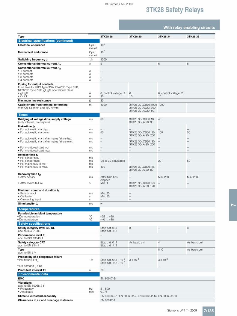
3TK28 Safety Relays
7/135Siemens LV 1 T · 2009
With relay enabling circuits
7
Type 3TK28 28 3TK28 30 3TK28 34 3TK28 35
Electrical specifications (continued)Electrical endurance Oper.
cycles105
Mechanical endurance Oper. cycles
107
Switching frequency z 1/h 1000
Conventional thermal current Ith A 5 6 5
Conventional thermal current Ith• 1 contact A --• 2 contacts A --• 3 contacts A --• 4 contacts A --
Fusing for output contactsFuse links LV HRC Type 3NA, DIAZED Type 5SB, NEOZED Type 5SE, gL/gG operational class• gL/gG A 6, control voltage: 2 6 6, control voltage: 2• Quick A 10 10 10
Maximum line resistance Ω 30 --
Cable length from terminal to terminal With Cu 1.5 mm2 and 150 nF/km
m 1000 3TK28 30-.CB30:10003TK28 30-.AJ20: 3003TK28 30-.AL20: 80
1000 --
TimesBridging of voltage dips, supply voltage (only internal, no outputs)
ms 30 3TK28 30-.CB30:103TK28 30-.A.20: 35
40
Make-time tE• For automatic start typ. ms -- -- -- --• For automatic start max. ms 80 3TK28 30-.CB30: 30
3TK28 30-.A.20: 200100 50
• For automatic start after mains failure typ. ms -- -- -- --• For automatic start after mains failure max. ms -- 3TK28 30-.CB30: 30
3TK28 30-.A.20: 200-- --
• For monitored start typ. ms -- -- -- --• For monitored start max. ms -- -- -- --
Release time tR• For sensor typ. ms -- -- -- --• For sensor max. ms Up to 30 adjustable -- 20 50• For mains failure typ. ms -- -- -- --• For mains failure max. ms 100 3TK28 30-.CB20: 25
3TK28 30-.A.20: 80-- --
Recovery time tW• After sensor ms After time has
elapsed-- Min. 250 Min. 250
• After mains failure s Min. 1 3TK28 30-.CB20: 503TK28 30-.A.20: 120
-- --
Minimum command duration tB• Sensor input ms Min. 25 --• ON button s Min. 25 --• Cascading input s -- --
Simultaneity tG ms ∞
TemperaturesPermissible ambient temperature
• During operation °C –25 ... +60• During storage °C –40 ... +80
Safety specificationsSafety integrity level SIL CL acc. to IEC 61508
Stop cat. 0: 3 Stop cat. 1: 2
3 -- 3
Performance level PLacc. to ISO 13849-1
--
Safety category CAT acc. to EN 954-1
Stop cat. 0: 4Stop cat. 1: 3
As basic unit 4 As basic unit
Type acc. to EN 574
-- -- III C As basic unit
Probability of a dangerous failure • Per hour (PFHD) 1/h Stop cat. 0: 3 x 10⁻⁸
Stop cat. 1: 2 x 10-73 x 10-8 3 x 10⁻⁸
• On demand (PFD) -- -- --
Proof-test interval T1 a 20
Environmental dataEMC EN 60947-5-1
Vibrations acc. to EN 60068-2-6• Frequency Hz 5 .. 500• Amplitude mm 0.075
Climatic withstand capability EN 60068-2-1, EN 60068-2-2, EN 60068-2-14, EN 60068-2-30
Clearances in air and creepage distances EN 60947-1
LV1T_2009_Gesamtbuch_EN.book Seite 135 Donnerstag, 26. Februar 2009 2:00 14
© Siemens AG 2009

3TK28 Safety Relays
With relay enabling circuits
7/136 Siemens LV 1 T · 2009
7
■ Dimensional drawings
3TK28 21 to 3TK28 24, 3TK28 30 with screw terminals
3TK28 25 up to 3TK28 28, 3TK28 34, 3TK28 35with screw terminals
1) For standard mounting rail TH 35 according to EN 60715.
3TK28 21 to 3TK28 24, 3TK28 30 with spring-type terminals
3TK28 25 to 3TK28 28, 3TK28 34, 3TK28 35with spring-type terminals
■ Schematics
Legend FKx.x: Enabling circuitsSx.x: Sensor terminals (test connectors)RFx.x: Feedback circuit terminalsMKx.x: Indicating circuit terminals
22,515
NSC0_00671b
120
8768 74110
11594
655
74
102
83
1)
139
9168 118
NSC0_00672b
3745
11594
65
74
102
106
83
5
1)
22,515
NSC0_00674b
120
9475 74110
1155
72,5
103
84
1)
5
75
3745
73
98 139
118
102
115
84 108
NSC0_00673b
1)
3TK28 21 3TK28 22, 3TK28 23 3TK28 24
A1L/+
NS
B0_
0185
8b
Y1RF1.1
Y2RF1.2
13FK1.1
23FK2.1
N/-A2
41MK1.1
MK1.242
FK1.214
FK2.224
FK3.234
=
~
33FK3.1
Logic
A1L/+
NS
B0_
0185
9a
Y11S1.1
Y12S1.2
Y33RF1.1
13FK1.1
N/-A2
S2.1Y21
S2.2Y22
RF1.2Y34
FK1.214
FK2.224
=
~
23FK2.1
Logic
A1L/+
NS
B0_
0186
0
Y1RF1.1
Y2RF1.2
13FK1.1
N/-A2
FK1.214
FK2.224
=
~
23FK2.1
Logic
LV1T_2009_Gesamtbuch_EN.book Seite 136 Donnerstag, 26. Februar 2009 2:00 14
© Siemens AG 2009

3TK28 Safety Relays
7/137Siemens LV 1 T · 2009
With relay enabling circuits
7
■ Schematics
3TK28 25
3TK28 26-.BB40
3TK28 26-.BB41/-.BB42/-.BB44
3TK28 26-.CW30
3TK28 26-.CW31/-.CW32/-.CW34
3TK28 27, 3TK28 28
3TK28 30
Legend FKx.x: Enabling circuitsSx.x: Sensor terminals (test connectors)RFx.x: Feedback circuit terminalsMKx.x: Indicating circuit terminalsPE: PE/ground conductor terminalTx: Test signal terminalEIN: Start signal terminal1-/2-kan: Parameter terminal switchover, one/two-channelAS/ÜS: Parameter terminal switchover, automatic/monitored
startKAS/BS: Terminal, cascading input/normal switchingtv: Time-delayed outputs
A1L/+
NS
B0_
0186
1a
Y11S1.1
Y12S1.2
Y21S1.3
Y22S1.4
N/-A2
PEPE
RF1.1Y33
RF1.2Y34
FK2.224
FK3.234
=
~
AS/ÜS1.1Y43
MK1.242
MK2.252
13FK1.1
33FK3.1
AS/ÜS1.2Y44
FK1.214
23FK2.1
41MK1.1
51MK2.1
Y101-/2-kan
Logic
A1DC24 V
NS
B0_
0186
2a
Y12S1.1
T1T1
Y33EIN
T3T3
0VA2
TST2
FK2.2 FK3.2
=
=
S1.2Y22
FK1.2 FK4.2 MK1.2
1KAS/BS
43FK4.1
51MK1.1
RFY34
MK174
MK264
13FK1.1
23FK2.1
33FK3.1
Logic
A1DC24 V
Y12S1.1
T1T1
Y33EIN
T3T3
0VA2
TST2
=
=
S1.2Y22
1KAS/BS
57FK4.1
61MK2.1
RFY34
MK174
MK284
13FK1.1
23FK2.1
47FK3.1
FK2.224
FK3.248
FK1.214
FK4.258
MK2.262
MK1.232
31MK1.1
Logic
NS
B0_
0200
2
A1DC24 V
NS
B0_
0186
3a
Y12S1.1
T1T1
Y33EIN
T3T3
0VA2
TST2
FK2.224
FK3.234
=
~
S1.2Y22
FK1.214
FK4.244
MK1.252
1KAS/BS
43FK4.1
51MK1.1
RFY34
MK1.163
MK1.264
13FK1.1
23FK2.1
33FK3.1
Logic
A1DC24 V
NS
B0_
0200
3
Y12S1.1
T1T1
Y33EIN
T3T3
0VA2
T2T2
=
~
S2.1Y22
1KAS/BS
57FK4.1
61MK2.1
RFY34
MK1.173
MK1.274
13FK1.1
23FK2.1
47FK3.1
FK2.224
FK3.248
FK1.214
FK4.258
MK2.262
MK1.232
31MK1.1
Logic
A1L/+
Y11S1.1
Y12S1.2
Y21S1.3
Y22S1.4
N/-A2
PEPE
RF1.1Y33
RF1.2Y34
FK2.224
MK1.232
=
~
FK3.244
FK4.254
13FK1.1
31MK1.1
FK1.214
23FK2.1
43FK3.1
53FK4.1
Y101-/2-kan
Logic
NS
B0_
0186
6c
A1L/+
NS
B0_
0186
7b
33FK3.1
43FK4.1
13FK1.1
23FK2.1
N/-A2
MK1.252
FK3.234
FK4.244
=
~
51MK1.1
FK2.224
FK1.214
Logic
LV1T_2009_Gesamtbuch_EN.book Seite 137 Donnerstag, 26. Februar 2009 2:00 14
© Siemens AG 2009

3TK28 Safety Relays
With contactor relay enabling circuits
7/138 Siemens LV 1 T · 2009
7
■ Design
The solid-state safety relays can be used in EMERGENCY-STOP devices according to EN 418 and in safety circuits according to EN 60204-1 (11.98), for example, for moving covers and protec-tive doors. Depending on the device type and the external cir-cuit, the maximum category that can be achieved is Category 4 of EN 954-1 or SIL 3 according to IEC 61508.
With these devices, solid-state safety relays are connected with contactor relays. The combination is supplied as a complete unit, fully wired up and tested, for snapping onto a standard mounting rail. This unit combines the advantages of a solid-state safety relay and those of contactor relays with positively-driven contacts in a single device. It has been certified by the appropri-ate authorities as a complete unit.
Basic units, Category 3
The 3TK28 50, 3TK28 51 and 3TK28 52 solid-state safety relays have two contactor relays snapped onto the safety solid-state unit as floating switching blocks. Three LEDs indicate the oper-ating state and the function. During operation, all internal circuit elements are monitored cyclically for faults. Up to Category 3 ac-cording to EN 954-1 is achieved, depending on the external circuit.
Basic units, Category 4
The 3TK28 53 solid-state safety relay has two contactor relays snapped onto the safety solid-state units as floating switching blocks, as well as a safe solid-state output, a safe input for cas-cading and one input for normal switching duty. Three LEDs in-dicate the operating state and the function.
During start-up, the device runs through a self-test in which the internal electronics are checked for correct functioning. During operation, all internal circuit elements are monitored cyclically for faults.
Expansion units, namely 3TK28 30, 3TK28 56, 3TK28 57, 3RA7 11 to 3RA7 14, as well as external actuators or loads can be connected using the safe solid-state output (terminal 2). Cas-cading with the 3TK28 41, 3TK28 42, 3TK28 45 and 3TK28 53 safety relays as well as with the 3RA7 11 load feeder is also pos-sible using the safe solid-state output (terminal 2).
Mounting
For snap-on mounting on TH 35 standard mounting rail accord-ing to EN 60715. Screw fixing is also possible for the devices by means of 2 additional 3RP19 03 push-in lugs.
■ Function
Basic units
3TK28 50 to 3TK28 52
The devices 3TK28 50 to 3TK28 52 each have one sensor input and a varying number of contactor relay enabling circuits and signaling outputs. If the signal is no longer applied to the sensor input, the enabling circuits are disconnected immediately.
Legend
Sensor interfaceSx: Sensor input
Safety logicAS/ÜS: Automatic or monitored start depending on the parameterization
Parameters1-/2-channel: One-channel / two-channel sensor connectionAS/ÜS: Automatic or monitored start depending on the parameterization
Actuator interfaceFKhs: Enabling circuit, contactor relay (floating)MKhs: Signaling circuit, contactor relay (floating)NO: NO contact NC: NC contact
NS
C0_
0068
9a
S
1
FK
hs
FK
hs
FK
hs
(NO)
(NO)
(NO)
3TK28 50 basic unit
1-/2-channel
AS/ÜS
AS/ÜS
NS
C0_
0069
0a
S1FKhs
FKhs
MKhs
AS/ÜS
AS/ÜS (NO)
(NO)
(NC)
3TK28 51 basic unit
1-/2-channel
NS
C0_
0069
1a
S
1
FK
hs
FK
hs
FK
hs
FK
hs
FK
hs
MK
hs
FK
hs
AS/ÜS
AS/ÜS (NO)
(NO)
(NO)
(NO)
(NO)
(NO)
(NO)
3TK28 52 basic unit
1-/2-channel
LV1T_2009_Gesamtbuch_EN.book Seite 138 Donnerstag, 26. Februar 2009 2:00 14
© Siemens AG 2009
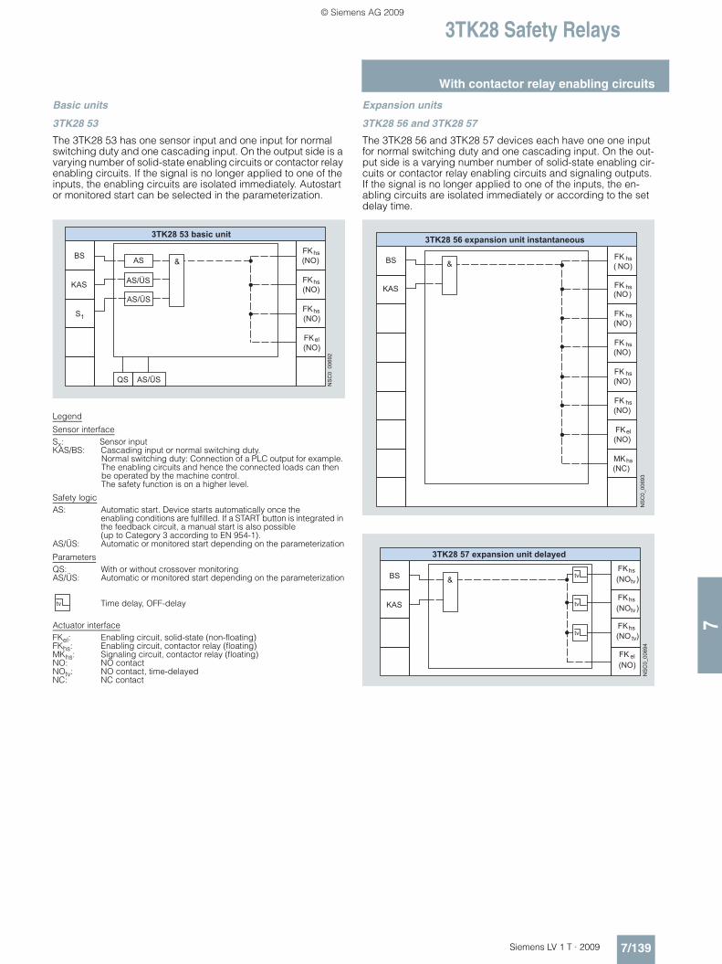
3TK28 Safety Relays
7/139Siemens LV 1 T · 2009
With contactor relay enabling circuits
7
Basic units
3TK28 53
The 3TK28 53 has one sensor input and one input for normal switching duty and one cascading input. On the output side is a varying number of solid-state enabling circuits or contactor relay enabling circuits. If the signal is no longer applied to one of the inputs, the enabling circuits are isolated immediately. Autostart or monitored start can be selected in the parameterization.
Legend
Sensor interfaceSx: Sensor inputKAS/BS: Cascading input or normal switching duty.
Normal switching duty: Connection of a PLC output for example. The enabling circuits and hence the connected loads can then be operated by the machine control. The safety function is on a higher level.
Safety logicAS: Automatic start. Device starts automatically once the
enabling conditions are fulfilled. If a START button is integrated in the feedback circuit, a manual start is also possible (up to Category 3 according to EN 954-1).
AS/ÜS: Automatic or monitored start depending on the parameterization
ParametersQS: With or without crossover monitoringAS/ÜS: Automatic or monitored start depending on the parameterization
Time delay, OFF-delay
Actuator interfaceFKel: Enabling circuit, solid-state (non-floating)FKhs: Enabling circuit, contactor relay (floating)MKhs: Signaling circuit, contactor relay (floating)NO: NO contact NOtv: NO contact, time-delayedNC: NC contact
Expansion units
3TK28 56 and 3TK28 57
The 3TK28 56 and 3TK28 57 devices each have one one input for normal switching duty and one cascading input. On the out-put side is a varying number number of solid-state enabling cir-cuits or contactor relay enabling circuits and signaling outputs. If the signal is no longer applied to one of the inputs, the en-abling circuits are isolated immediately or according to the set delay time.
NS
C0_
0069
2
BS
KAS
S
1
FK
hs (NO)
FK
hs (NO)
FK
el (NO)
FK
hs (NO)
AS/ÜS
AS
&
AS/ÜS
QS
AS/ÜS
3TK28 53 basic unit
tv
NS
C0_
0069
3
BS
KAS
FK
hs
FK
hs
FK
hs
FK
hs
FK
hs
FK
hs
FK
el
MK
hs
&
( NO)
(NO)
(NO)
(NO)
(NO)
(NO)
(NO)
(NC)
3TK28 56 expansion unit instantaneous
tv
NS
C0_
0069
4
BS
KAS
FK
hs
FK
hs
FK
hs
FK
el
&
tv
tv
tv
tv(NO
(NO
(NO)
(NO
)
)tv
3TK28 57 expansion unit delayed
tv)
LV1T_2009_Gesamtbuch_EN.book Seite 139 Donnerstag, 26. Februar 2009 2:00 14
© Siemens AG 2009

3TK28 Safety Relays
With contactor relay enabling circuits
7/140 Siemens LV 1 T · 2009
7
■ Technical specifications
Type 3TK28 50 3TK28 51 3TK28 52 3TK28 53 3TK28 53-0AB1 3TK28 56 3TK28 57
General dataStandards EN 60204-1, EN ISO 12100, EN 954-1, IEC 61508
Test certificates TÜV, UL, CSA
Safety-oriented output contacts• Instantaneous FKrel 3 2 6 3 6 3• Time-delayed FKrel (tv) -- -- -- -- -- --
Safety-oriented semiconductor outputs• Instantaneous FKel -- 1• Time-delay FKel (tv) -- --
Signaling contacts MKrel -- 1 -- 1 --
Semiconductor signaling outputs MKrel --
Sensor inputs S 1 --
Cascading inputs KAS/BS -- 2
Degree of protection acc. to EN 60529 • Enclosure IP20• Terminals IP20
Shock resistance sine wave g/ms 5/11 8/10 and 15/5
Permissible mounting positions Any
Touch protectionacc. to EN 61140 or EN 60900
Finger-safe
Height mm 89
Width mm 90
Depth mm 112 150 112 150 112
Weight kg 0.850 0.750
Connection type Screw terminals
• Terminal screw M 3 (standard screwdriver, size 2 and Pozidriv 2)• Solid mm2 1 x (0.2 ... 2.5)/2 x (0.2 ... 1.0)• Finely stranded with end sleeve mm2 1 x (0.25 ... 2.5)/2 x (0.25 ... 1.0)• AWG cables, solid or stranded AWG 2 x (24 ... 12)• Tightening torque Nm 0.8 … 1.2
Connection type Spring-type terminals
• Solid mm2 2 x (0.2 ... 2.5)• Finely stranded, with end sleeves
acc. to DIN 46228mm2 2 x (0.25 ... 2.5)
• Finely stranded mm2 2 x (0.25 ... 2.5)• Stripped length mm 10
Electrical specificationsRated control supply voltage Us V 24 DC, 24/115/230 AC 24 DC
Measurement voltage V --
Response value Uresp V --
Operating range• AC operation V 0.9 ... 1.15 × Us --• DC operation V 0.85 ... 1.1 × Us 0.85 ... 1.1 × Us
Rated insulation voltage Ui• For control circuit V 50• For outputs V 690
Rated impulse withstand voltage Uimp• For control circuit V 500• For outputs V 6000
Rated power at Us W 8.5
Frequency ranges Hz 50/60 --
Rated operational current Ie (relay outputs) at• AC-15 at 115 V A -- -- -- --• AC-15 at 230 V A 6 6 -- --• DC-13 at 24 V A 10 10,
Auxiliary switch blocks: 6
10 10, Auxiliary switch blocks: 6
• DC-13 at 115 V A -- -- -- --• DC-13 at 230 V A -- -- -- --
Rated operational current Ie (semiconductor outputs) at• DC-15 at 24 V A --• DC-15 at 230 V A --
LV1T_2009_Gesamtbuch_EN.book Seite 140 Donnerstag, 26. Februar 2009 2:00 14
© Siemens AG 2009

3TK28 Safety Relays
7/141Siemens LV 1 T · 2009
With contactor relay enabling circuits
7
Type 3TK28 50 3TK28 51 3TK28 52 3TK28 53 3TK28 53-0AB1 3TK28 56 3TK28 57
Electrical specifications (continued) Electrical endurance Operat-
ing cycles
See "3RH1 Characteristic Curves"
Mechanical endurance Operat-ing cycles
3 x 10⁷
Switching frequency z 103
Conventional thermal current Ith A --
Conventional thermal current Ith• 1 contact A --• 2 contacts A --• 3 contacts A --• 4 contacts A --
Fusing for output contactsFuse links LV HRC Type 3NA, DIAZED Type 5SB, NEOZED Type 5SE • gL/gG A 10• Quick A --
Maximum line resistance Ω 250 500
Cable length from terminal to terminalWith Cu 1.5 mm2 and 150 nF/km
m 2000
TimesBridging of voltage dips, supply voltage(only internal, no outputs)
ms 5
Make-time tE• For automatic start typ. ms 100 60 --• For automatic start max. ms 200 100 --• For automatic start after mains failure typ. ms 350 6000 6000• For automatic start after mains failure max. ms 500 7000 7000• For monitored start typ. ms 60 60 --• For monitored start max. ms 100 100 --
Release time tR• For sensor typ. ms 30 50 --• For sensor max. ms 50 60 300
adjustable• For mains failure typ. ms 100 120 120• For mains failure max. ms 120 120 120
Recovery time tW• After sensor ms 20 500• After mains failure s 0.02 7
Minimum command duration tB• Sensor input ms 20 45 --• ON button s 20 0.2 ... 5 --• Cascading input ms 20 45 45
Simultaneity tG ms ∞
TemperaturesPermissible ambient temperature
• During operation °C –25 ... +60• During storage °C –40 ... +80
Safety specificationsSafety integrity level SIL CL acc. to IEC 61508
2 --
Performance level PLacc. to ISO 13849-1
--
Safety category CATacc. to EN 954-1
3 4 As basic unit
Typeacc. to EN 574
--
Probability of a dangerous failure 1/h• Per hour (PFHD) 1/h 1.52 x 10⁻⁸ 5 x 10-11 9.8 x 10⁻¹¹
• On demand (PFD) -- -- -- --
Proof-test interval T1 a 10
Environmental dataEMC IEC 60947-5-1,
IEC 60000-4-3, IEC 60000-4-5, IEC 60000-4-6
Vibrationsacc. to EN 60068-2-6• Frequency Hz 5 ... 500• Amplitude mm 0.075
Climatic withstand capability EN 60068-2-78
Clearances in air and creepage distances EN 60947-1
LV1T_2009_Gesamtbuch_EN.book Seite 141 Donnerstag, 26. Februar 2009 2:00 14
© Siemens AG 2009
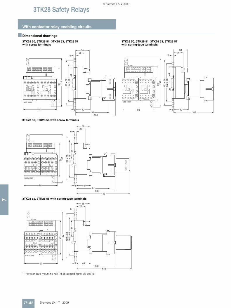
3TK28 Safety Relays
With contactor relay enabling circuits
7/142 Siemens LV 1 T · 2009
7
■ Dimensional drawings
3TK28 50, 3TK28 51, 3TK28 53, 3TK28 57 with screw terminals
3TK28 50, 3TK28 51, 3TK28 53, 3TK28 57 with spring-type terminals
3TK28 52, 3TK28 56 with screw terminals
3TK28 52, 3TK28 56 with spring-type terminals
1) For standard mounting rail TH 35 according to EN 60715.
��
��������
� ��
���
� �
��
��
� �
��
�
��
�����
���
��
��
�� ���
�����
�
�����
�
��
� �������
�
�
���
��
��
��
� �������
��
���
�����
�
�����
�
��
�
�
���
��
��
��
��
��
�� ���
�����
�
�����
�
��
� ������
�
�
���
��
���
��
LV1T_2009_Gesamtbuch_EN.book Seite 142 Donnerstag, 26. Februar 2009 2:00 14
© Siemens AG 2009

3TK28 Safety Relays
7/143Siemens LV 1 T · 2009
With special functions
7
■ Design
The 3TK28 10 safety relays with special functions operate with internal contactor relays with positively-driven contacts.
In a redundant circuit, operation of the internal controls is moni-tored. If a safety relay fails, it will always switch to the de-ener-gized and consequently safe state. The fault is detected and the safety relay can no longer be switched on.
Enabling contacts (FK)
Safety related operation must be performed by safe output con-tacts, known as enabling contacts. Enabling contacts are always NO contacts and switch without delay.
Signaling contacts (MK)
NC contacts are used as signaling contacts but they are not per-mitted to perform functions with relevance for safety. An en-abling contact can also be used as a signaling contact. A signal-ing contact cannot, however, be used as an enabling contact.
Expansion units
If the enabling contacts of the basic unit are inadequate, expan-sion units can be used. An expansion unit has 4 enabling con-tacts. Expansion units are not allowed to be operated separately in safety-related switching circuits; they must be combined with a basic unit. One enabling contact of the basic unit is required for connecting an expansion unit. The category of a control sys-tem with expansion unit corresponds to that of the basic unit.
■ Function
3TK28 10-0 standstill monitor
The 3TK2810-0 safe standstill monitor measures a voltage of the decelerating motor, which is induced by residual magnetism, at 3 terminals of the stator winding. When the induction voltage ap-proximates to 0, the monitor interprets this to mean that the motor has stopped and the output relay is activated. To be able to adapt the monitor to different motors and applications, it is pos-sible to adjust the voltage threshold Uan below which the 3TK2810-0 detects a stoppage. Also adjustable is the length of time over which Uan must be undershot in order for a stoppage to be detected and the output circuit enabled (downtime ts).
The device also detects wire breaks between the measuring in-puts L1/L2/L3. If a wire break is detected, the output relay will adopt the safe position (the same as with a running motor).
Legend
Sensor interfaceSx: Sensor input
Actuator interfaceFKrel: Enabling circuit, relay contact (floating)MKel: Signaling circuit, solid-state output (non-floating)MKrel: Signaling circuit, relay contact (floating)NO: NO contact NC: NC contactCO: Changeover contact
NS
B0_
0187
1
3TK28 10-0 basic unit delayed
FKrel(NC)
FKrel(NC)
FKrel(NC)
FKrel(NO)
MKrel(NC)
MKrel(NC)
MKrel(CO)
S1
Uan
LV1T_2009_Gesamtbuch_EN.book Seite 143 Donnerstag, 26. Februar 2009 2:00 14
© Siemens AG 2009

3TK28 Safety Relays
With special functions
7/144 Siemens LV 1 T · 2009
7
■ Technical specifications
Type 3TK28 10
General dataStandards EN 60204-1, EN ISO 12100, EN 954-1, IEC 61508
Test certificates TÜV, UL, CSA
Safety-oriented output contacts• Instantaneous FKrel 4• Time-delayed FKrel (tv) --
Safety-oriented semiconductor outputs• Instantaneous FKel --• Time-delay FKel (tv) --
Signaling contacts MKrel 1
Semiconductor signaling outputs MKrel 2
Sensor inputs S 1
Cascading inputs KAS/BS --
Degree of protection acc. to EN 60529 • Enclosure IP40• Terminals IP20
Shock resistance sine wave g/ms 8/10
Permissible mounting positions Any
Touch protection acc. to EN 61140 or EN 60900
Finger-safe
Height mm 106: screw terminals; 108: spring-type terminals
Width mm 45
Depth mm 116
Weight kg 0.500
Connection type Screw terminals
• Terminal screw M 3 (standard screwdriver, size 2 and Pozidriv 2)• Solid mm2 1 x (0.5 ... 4)/2 x (0.5 ... 2.5)• Finely stranded with end sleeve mm2 1 x (0.5 ... 2.5)/2 x (0.5 ... 1.5)• AWG cables, solid or stranded AWG 2 x (24 ... 16)• Tightening torque Nm 0.8 … 1.2
Connection type Spring-type terminals
• Solid mm2 2 x (0.25 ... 1.5)• Finely stranded, with end sleeves acc. to DIN 46228 mm2 2 x (0.25 ... 1.0)• Finely stranded mm2 2 x (0.25 ... 1.5)
Electrical specificationsRated control supply voltage Us V 24 DC, 230/400 AC
Operating range• AC operation V 0.8 ... 1.1 × Us• DC operation V 0.9 ... 1.15 × Us
Measurement voltage V Max. 690
Response value Uresp V 20 ... 400 adjustable
Rated insulation voltage Ui• For control circuit V 300• For outputs V 690
Rated impulse withstand voltage Uimp• For control circuit V 6/4• For outputs V 6
Rated power at Us W 3
Frequency ranges Hz 50/60
Rated operational current Ie (relay outputs) at• AC-15 at 115 V A --• AC-15 at 230 V A 3 (NO contacts); 2 (NC contacts)• DC-13 at 24 V A 2• DC-13 at 115 V A --• DC-13 at 230 V A --
Rated operational current Ie (semiconductor outputs) at• DC-13 at 115 V A 0.1• DC-13 at 230 V A --
Electrical endurance Operat-ing cycles
2 x 10⁵
Mechanical endurance Operat-ing cycles
5 x 10⁷
Switching frequency z 1/h 1200
LV1T_2009_Gesamtbuch_EN.book Seite 144 Donnerstag, 26. Februar 2009 2:00 14
© Siemens AG 2009

3TK28 Safety Relays
7/145Siemens LV 1 T · 2009
With special functions
7
■ Technical specifications
Type 3TK28 10
Electrical specifications (continued)Conventional thermal current Ith A 5, summation current max. 8
Conventional thermal current Ith• 1 contact A 5• 2 contacts A 5• 3 contacts A 5• 4 contacts A --
Fusing for output contactsFuse links LV HRC Type 3NA, DIAZED Type 5SB, NEOZED Type 5SE, gL/gG operational class• gL/gG --• Quick A 5
Maximum line resistance Ω --
Cable length from terminal to terminalWith Cu 1.5 mm2 and 150 nF/km
m --
TimesRelease time tR• For sensor typ. ms --• For sensor max. ms 6 adjustable• For mains failure typ. ms --• For mains failure max. ms --
Simultaneity tG ms ∞
TemperaturesPermissible ambient temperature
• During operation °C –25 ... +60• During storage °C –40 ... +75
Safety specificationsSafety integrity level SIL CL acc. to IEC 61508
3
Performance level PLacc. to ISO 13849-1
e
Safety category CAT acc. to EN 954-1
4
Probability of a dangerous failure• Per hour (PFHD) 1/h 1.49 x 10⁻⁹
• On demand (PFD) --
Proof-test interval T1 a 20
LV1T_2009_Gesamtbuch_EN.book Seite 145 Donnerstag, 26. Februar 2009 2:00 14
© Siemens AG 2009

3TK28 Safety Relays
With special functions
7/146 Siemens LV 1 T · 2009
7
■ Dimensional drawings
3TK28 10with screw terminals
1) For standard mounting rail TH 35 according to EN 60715.
3TK28 10with spring-type terminals
■ Schematics
3TK28 10-0BA0.
3TK28 10-0GA0.
3TK28 10-0JA0.
Legend FKx.x: Enabling circuitsMKx.x: Indicating circuit terminalsM-MK: Ground signaling circuitsSx.x: Sensor terminals (test connectors)SKx: Control terminals
139
9168 118
NSC0_00672b
3745
11594
65
74
102
106
835
1)
5
75
3745
73
98 139
118
102
115
84 108
NSC0_00673b
1)
A1DC24 V
NS
B0_
0186
8a
A4M-MK
X1SK1
X2SK2
0VA2
S1.1L1
FK1.212
FK2.224
=
=
MK164
MK3.252
FK3.234
FK4.244
51MK3.1
33FK3.1
43FK4.1
S1.2L2
S1.3L3
MK274
MK3.354
11FK1.1
23FK2.1
X3SK3
A3DC24 V
Logic
A1AC230 V
NS
B0_
0186
9a
A4M-MK
X1SK1
X2SK2
0VA2
S1.1L1
FK1.212
FK2.224
=
~
MK164
MK3.252
FK3.234
FK4.244
51MK3.1
33FK3.1
43FK4.1
S1.2L2
S1.3L3
MK274
MK3.354
11FK1.1
23FK2.1
X3SK3
A3DC24 V
Logic
A1AC400 V
NS
B0_
0187
0a
A4M-MK
X1SK1
X2SK2
0VA2
S1.1L1
FK1.212
FK2.224
=
~
MK164
MK3.252
FK3.234
FK4.244
51MK3.1
33FK3.1
43FK4.1
S1.2L2
S1.3L3
MK274
MK3.354
11FK1.1
23FK2.1
X3SK3
A3DC24 V
Logic
LV1T_2009_Gesamtbuch_EN.book Seite 146 Donnerstag, 26. Februar 2009 2:00 14
© Siemens AG 2009
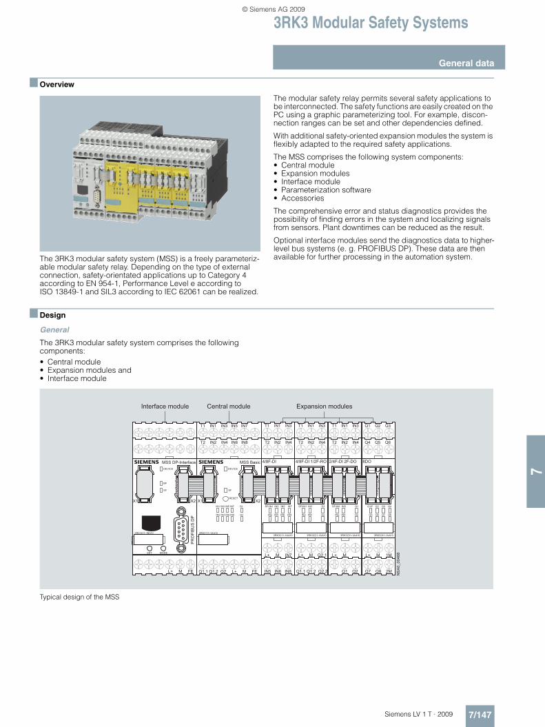
3RK3 Modular Safety Systems
7/147Siemens LV 1 T · 2009
General data
7
■ Overview
The 3RK3 modular safety system (MSS) is a freely parameteriz-able modular safety relay. Depending on the type of external connection, safety-orientated applications up to Category 4 according to EN 954-1, Performance Level e according to ISO 13849-1 and SIL3 according to IEC 62061 can be realized.
The modular safety relay permits several safety applications to be interconnected. The safety functions are easily created on the PC using a graphic parameterizing tool. For example, discon-nection ranges can be set and other dependencies defined.
With additional safety-oriented expansion modules the system is flexibly adapted to the required safety applications.
The MSS comprises the following system components:• Central module• Expansion modules• Interface module• Parameterization software• Accessories
The comprehensive error and status diagnostics provides the possibility of finding errors in the system and localizing signals from sensors. Plant downtimes can be reduced as the result.
Optional interface modules send the diagnostics data to higher-level bus systems (e. g. PROFIBUS DP). These data are then available for further processing in the automation system.
■ Design
General
The 3RK3 modular safety system comprises the following components:• Central module• Expansion modules and • Interface module
Typical design of the MSS
T1 IN1 IN3 IN5 IN7
T2 IN2 IN4 IN6 IN8
Q1.1 Q1.2 Q2 L+ M FE
X1 X2
DEVICE
SF
RESET
IN1 IN3 IN5 IN7 Q1
IN2 IN4 IN6 IN8 Q2
3RK3111-1AA10
MSS Basic
SF/IN1 IN3 Q1
IN2 IN4 Q2
T1 IN1 IN3
T2 IN2 IN4
L+ M Q2.1
Q1.1 Q1.2 Q2.2
3RK3221-1AA10
4/8F-DI 1/2F-RO
SF/IN1 IN3 Q1
IN2 IN4 Q2
T1 IN1 IN3
T2 IN2 IN4
L+ M
Q1 Q2
3RK3231-1AA10
2/4F-DI 2F-DO
Q1/F Q2 Q3 Q4
Q5 Q6 Q7 Q8
Q1 Q2 Q3
Q4 Q5 Q6
L+ M 1M
Q7 Q8 2M
3RK3241-1AA10
8DO
SF/IN1 IN3 IN5 IN7
IN2 IN4 IN6 IN8
T1 IN1 IN3
T2 IN2 IN4
L+ M IN7
IN5 IN6 IN8
3RK3211-1AA10
4/8F-DI
X1 X2
DEVICE
SF
3RK3511-1BA10
MSS DP-Interface
PR
OFI
BU
S D
P
L+ M FE
BF
SET MODE
NS
A0_
0046
8
Central moduleInterface module Expansion modules
LV1T_2009_Gesamtbuch_EN.book Seite 147 Donnerstag, 26. Februar 2009 2:00 14
© Siemens AG 2009

3RK3 Modular Safety Systems
Modules
7/148 Siemens LV 1 T · 2009
7
Central module
The 3RK3 Basic central module is the basic unit of the MSS mod-ular safety system for every system configuration. It controls the expansion modules and supplies data to the DP interface. The central module also stores the parameterization which performs logic operations for input signals and output signals.
The 3RK3 Basic central module has:• 8 safety-oriented, freely configurable sensor inputs• 1 safety-oriented two-channel relay output• 1 safety-oriented two-channel solid-state output
Up to 7 expansion modules can be connected to the 3RK3 Basic central module.
Data exchange with the higher-level automation system takes place through an additional bus module (DP interface) or through PROFIBUS. The 3RK3 Basic central module can be pa-rameterized with the MSS ES engineering software.
Expansion modules
Using expansion modules, the functional scope of the MSS can be flexibly adapted to the requirements of the application. Ex-pansion modules are offered as safety-oriented and standard in-put modules, output modules and mixed modules. The module types can be combined as required.
4/8 F-DI expansion modules
The 4/8 F-DI expansion module has only safety-oriented inputs. With single-channel connection of the sensors, 8 different sen-sors can be connected. For two-channel connection, two inputs are grouped per sensor. It is thus possible to connect 4 different sensors. The sensor connection types can be mixed on the module.
The 4/8 F-DI expansion module has:• 8 single-channel inputs
2/4 F-DI 1/2 F-RO
The 2/4F-DI 1/2 F-RO expansion module has safety-oriented in-puts and outputs. With single-channel connection of the sen-sors, 4 different sensors can be connected. For two-channel connection, two inputs are grouped per sensor. It is thus possi-ble to connect 2 different sensors. The 2/4F-DI 1/2 F-RO expan-sion module has 2 safety-orientated relay outputs in single-chan-nel configuration. If a two-channel output is required, the relay outputs can be connected in series. The sensor connection types can be mixed on the module.
The 2/4 F-DI 1/2 F-RO expansion module has:• 4 single-channel inputs • 2 single-channel relay outputs
LV1T_2009_Gesamtbuch_EN.book Seite 148 Donnerstag, 26. Februar 2009 2:00 14
© Siemens AG 2009

3RK3 Modular Safety Systems
7/149Siemens LV 1 T · 2009
Modules
7
Expansion modules (continued)
2/4 F-DI 2 F-DO
The 2/4F-DI 2 F-DO expansion module has safety-oriented in-puts and outputs. With single-channel connection of the sen-sors, 4 different sensors can be connected. For two-channel connection, two inputs are grouped per sensor. It is thus possi-ble to connect 2 different sensors. The 2/4F-DI 1/2 F-DO expan-sion module has 2 safety-oriented solid-state outputs in two-channel configuration. The sensor connection types can be mixed on the module.
The 2/4 F-DI 2 F-DO expansion module has:• 4 single-channel inputs• 2 two-channel solid-state outputs
8 DO
The 8 DO expansion module has standard outputs (signaling outputs). No safety-oriented disconnection is allowed through these outputs.
The 8 DO expansion module has:• 8 single-channel solid-state standard outputs.
DP-Interface interface modules
The bus module (DP-Interface) is used for transferring diagnos-tics data and device status data to a higher-level PROFIBUS net-work. Here these exclusively non-safety-oriented data can be evaluated in the PLC or a B&B system.
The MSS supports among other things:• Baud rates up to 12 Mbit/s • Automatic baud rate detection• Cyclic services (DPV0) and acyclic services (DPV1)• Exchange of 32-bit cyclic data• Diagnostics using data record invocations
The bus module is integrated in the PROFIBUS network using a GSD. This is a standardized, vendor-independent specification with which the bus module can be integrated in practically all au-tomation systems.
LV1T_2009_Gesamtbuch_EN.book Seite 149 Donnerstag, 26. Februar 2009 2:00 14
© Siemens AG 2009

3RK3 Modular Safety Systems
Modules
7/150 Siemens LV 1 T · 2009
7
■ Function
The 3RK3 modular safety system can be used for all safety-re-lated applications in the manufacturing industry and offers the following functions:
Function Description
Monitoring functionsEMERGENCY-STOP With the EMERGENCY-STOP function, signals from EMERGENCY-STOP control
devices with positive-opening contacts are evaluated.
Protective door monitoring With the protective door function, signals from protective doors or protective flaps with positive-opening contacts a combination of NC and NO contacts are evaluated.
BWS monitoring (non-contact protective devices)
With the BWS function, signals from e. g. light curtains and laser scanners are evaluated.
Operating mode selector switches With the operating mode selector switch function, signals from an operating mode selector switch with NO contacts are evaluated. Up to 5 operating modes can be defined. The operating mode to be implemented can be freely configured in the downstream logic.
Switching mats With the switching mat function, signals from switching mats with NC contacts or crossover monitoring are evaluated.
Two-hand operator control With the two-hand operator control function, signals from a two-hand operator control device are evaluated.
Approval switches With the OK button function, signals from OK buttons with NO contact are evaluated.
Logic operation functionsAND, OR, XOR, NAND, NOR, negation (NEG), flip-flop (FF-RS)
Counter functionsCounter 0 -> 1 The safety relay supports the counting function "counter 0 -> 1". The count value
is changed only when there is a positive edge at the count inputs. The current count value can be counted forwards or backwards through one own count input each.
Counter 1 -> 0 The safety relay supports the counting function "For negative edge 1 -> 0". The count value is changed only when there is a negative edge. The current count value can be counted forwards or backwards through one own count input each.
Counter 0 -> 1/1 -> 0 The safety relay supports the counting function "For both edges". The count value is changed both when there is a positive edge and when there is a nega-tive edge. The current count value can be counted forwards or backwards through one own count input each.
Time functionsON delay, On delay (trigger), passing make contact, passing make contact (trigger),OFF delay, OFF delay (trigger), clock-pulsing
Start functionsManual and automatic start
Output functionsStandard outputs and fail-safe outputs can be actuated.
LV1T_2009_Gesamtbuch_EN.book Seite 150 Donnerstag, 26. Februar 2009 2:00 14
© Siemens AG 2009

3RK3 Modular Safety Systems
7/151Siemens LV 1 T · 2009
Modules
7
■ Technical specifications
General data
Device dataShock resistance (sine pulse) g/ms 15/11
Touch protection acc. to EN 61140 or EN 60529 IP20
Permissible mounting position Vertical mounting surface (+10°/-10°), deviating mounting positions are permitted for reduced ambient temperature
Minimum distances For heat dissipation through convection from the devices 25 mm to the ventilation openings (top and bottom)
Permissible ambient temperature• During operation °C -20 ... +60• Storage and transport °C -40 ... +85
Installation height above sea level m 2000
Safety specificationsSIL integrity level SIL CL acc. to IEC 61508 3
Performance level PL acc. to ISO 13849-1 e
Safety category CAT acc. to EN 954-1 4
Type acc. to EN 574 III C
Proof-test interval T1 20 years
Environmental dataEMC interference immunity IEC 60947-5-1
Vibrations• Frequency Hz 5 ... 500• Amplitude mm 0.75
Climatic withstand capability EN 60068-2-78Central moduleDevice dataNumber of sensor inputs (1-channel) 8
Number of test outputs 2
Number of outputs 1 relay output, two-channel1 solid-state output, two-channel
Dimensions H x W x D mm 111 x 45 x 124 screw terminals; 113 x 45 x 124 spring-type terminals
Weight g 300
Electrical specificationsRated control supply voltage Us acc. to IEC 61131-2
V 24 DC Device current supply through a power supply unit acc. to IEC 60 536 safety class (SELV or PELV)
Operating range 0.85 ... 1.15 x Us
Rated insulation voltage Ui V 300
Rated impulse voltage Uimp kV 4
Total current input mA 185
Rated power at Us W 4.5
Utilization category acc. to EN 60947-5-1 (relay outputs) • AC15 at 230 V A 2• DC13 at 24 V (semiconductor outputs) A 1• DC13 at 24 V A 1.5
Mechanical endurance during normal duty 10 x 106 operating cycles (relays)
Switching frequency z at rated operational current 1/h 1000
Conventional thermal current Ith A 2/1.5
Fusing for output contactsFuse links LV HRC Type 3NA, DIAZED Type 5SB, NEOZED Type 5SE• gL/gG operational class A 4• Operational class quick A 6
Safety specificationsProbability of a dangerous failure• Per hour (PFHd) 1/h 5.14 x 10⁻⁹ • On demand (PFD) 1/h 1.28 x 10⁻⁵
Parameters for cablesLine resistance Ω 100
Cable length from terminal to terminalWith Cu 1.5 mm2 and 150 nF/km m 1000
Conductor capacity nF 330
LV1T_2009_Gesamtbuch_EN.book Seite 151 Donnerstag, 26. Februar 2009 2:00 14
© Siemens AG 2009

3RK3 Modular Safety Systems
Modules
7/152 Siemens LV 1 T · 2009
7
4/8F-DI expansion modulesDevice dataNumber of sensor inputs (1-channel) 8
Number of test outputs 2
Dimensions H x W x D mm 111 x 22.5 x 124 screw terminals; 113 x 22.5 x 124 spring-type terminals
Weight g 160
Electrical specificationsRated control supply voltage Us acc. to IEC 61131-2 V 24 DC ±15 %
Operating range 0.85 ... 1.15 x Us
Rated insulation voltage Ui V 50
Rated impulse voltage Uimp V 500
Total current input mA 60
Rated power at Us W 2.5
Safety specificationsProbability of a dangerous failure• Per hour (PFHd) 1/h 1.89 x 10⁻⁹ • On demand (PFD) 1/h 4.29 x 10⁻⁶
Parameters for cablesLine resistance Ω 100
Cable length from terminal to terminalWith Cu 1.5 mm2 and 150 nF/km m 1000
Conductor capacity nF 3302/4F-DI 1/2F-RO expansion modulesDevice dataNumber of sensor inputs (1-channel) 4
Number of test outputs 2
Number of outputs 2 relay outputs, single-channel
Dimensions H x W x D mm 111 x 22.5 x 124 screw terminals; 113 x 22.5 x 124 spring-type terminals
Weight g 160
Electrical specificationsRated control supply voltage Us acc. to IEC 61131-2 V 24 DC ±15 %
Operating range 0.85 ... 1.15 x Us
Rated insulation voltage Ui V 50
Rated impulse voltage Uimp V 500
Total current input mA 85
Rated power at Us W 2
Utilization category acc. to EN 60947-5-1• AC15 at 230 V A 2• DC13 at 24 V A 1
Mechanical endurance during normal duty 10 x 106 operating cycles (relays)
Switching frequency z at rated operational current 1/h 1000
Continuous thermal current Ith A 1
Safety specificationsProbability of a dangerous failure• Per hour (PFHd) 1/h 3.79 x 10⁻⁹ • On demand (PFD) 1/h 5.85 x 10⁻⁶
Parameters for cablesLine resistance Ω 100
Cable length from terminal to terminalwith Cu 1.5 mm2 and 150 nF/km m 1000
Conductor capacity nF 330
LV1T_2009_Gesamtbuch_EN.book Seite 152 Donnerstag, 26. Februar 2009 2:00 14
© Siemens AG 2009

3RK3 Modular Safety Systems
7/153Siemens LV 1 T · 2009
Modules
7
2/4F-DI 2F-DO expansion modulesDevice dataNumber of sensor inputs (1-channel) 4
Number of test outputs 2
Number of outputs 2 solid-state outputs, two-channel
Dimensions H x W x D mm 111 x 22.5 x 124 screw terminals; 113 x 22.5 x 124 spring-type terminals
Weight g 160
Electrical specificationsRated control supply voltage Us acc. to IEC 61131-2 V 24 DC ±15 %
Operating range 0.85 ... 1.15 x Us
Rated insulation voltage Ui V 50
Rated impulse voltage Uimp V 500
Total current input mA 85
Rated power at Us W 2
Utilization category acc. to EN 60947-5-1• DC13 at 24 V A 1
Switching frequency z at rated operational current 1/h 1000
Conventional thermal current Ith A 1
Safety specificationsProbability of a dangerous failure• Per hour (PFHd) 1/h 2.7 x 10⁻⁹ • On demand (PFD) 1/h 8.34 x 10⁻⁶
Parameters for cablesLine resistance Ω 100
Cable length from terminal to terminalWith Cu 1.5 mm2 and 150 nF/km m 1000
Conductor capacity nF 3308DO expansion modulesDevice dataNumber of outputs 8
Dimensions H x W x D mm 111 x 22.5 x 124 screw terminals; 113 x 22.5 x 124 spring-type terminals
Weight g 160
Electrical specificationsRated control supply voltage Us acc. to IEC 61131-2 V 24 DC ±15 %
Operating range 0.85 ... 1.15 x Us
Rated insulation voltage Ui V 50
Rated impulse voltage Uimp V 500
Total current input mA 60
Rated power at Us W 1.5
Utilization category acc. to EN 60947-5-1 (relay outputs)• DC13 at 24 V A 0.5
Switching frequency z at rated operational current 1/h 1000
Continuous thermal current Ith A 1Interface moduleDevice dataCommunication 32-bit cyclic data can be exchanged by PLC (DPV0);
acyclic communication through DPV1
Dimensions H x W x D mm 111 x 45 x 124 screw terminals; 113 x 45 x 124 spring-type terminals
Weight g 270
Electrical specificationsRated control supply voltage Us acc. to IEC 61131-2 V 24 DC ±15 %
Operating range 0.85 ... 1.15 x Us
Rated insulation voltage Ui V 50
Rated impulse voltage Uimp V 500
LV1T_2009_Gesamtbuch_EN.book Seite 153 Donnerstag, 26. Februar 2009 2:00 14
© Siemens AG 2009

3RK3 Modular Safety Systems
Modules
7/154 Siemens LV 1 T · 2009
7
■ Dimensional drawings
Central module with screw terminals
Expansion module with screw terminals
Interface module with screw terminals
1) For standard mounting rail TH 35 according to EN 60715.
Central module with spring-type terminals
Expansion module with spring-type terminals
Interface module with spring-type terminals
NSA0_00473
106
111
118,
513
8,5
102
1155119
80
74
1)
3745
8868 101,
511
0,5
115
1)
5119 N
SA
0_00
471
73,5
1522,5
7,24
NSA0_00469
106
111
119,
513
9,5
102
1155119
80
74
1)
3745
NSA0_00474
74
1)
3745
88 110
102
113
118,
513
8,5
1155119
110,
5
9475 105
NS
A0_
0047
2
115
1)
5119
73,5
22,515
7,24
NSA0_00470
74
1)
3745
88 110
102
113
118,
513
8,5
1155119
LV1T_2009_Gesamtbuch_EN.book Seite 154 Donnerstag, 26. Februar 2009 2:00 14
© Siemens AG 2009

Interface Converters
7/155Siemens LV 1 T · 2009
3RS17 interface converters
7
■ Overview
Interface converters perform the coupling function for analog signals on both the input side and the output side. They are in-
dispensable when processing analog values with electronic controls. Under harsh industrial conditions in particular, it is often necessary to transmit analog signals over long distances. This means that electrical separation is essential due to the different supply systems. The resistance of the wiring causes voltage dif-ferences and losses which must be prevented.
Electromagnetic faults and overvoltages can affect the signals on the input side in particular or even destroy the analog mod-ules. All terminals of the 3RS17 interface converters are safe up to a voltage of 30 V DC and protected against interchangeing poles. Short-circuit protection is an especially important function for the outputs.
The devices are EMC-tested according to• EN 61000-6-2 (Electromagnetic compatibility (EMC) - Generic
standards - Immunity for industrial environments)• EN 61000-6-4 (Electromagnetic compatibility (EMC) - Generic
standards - Emission standard for industrial environments)
The analog signals comply with • IEC 60381-1, -2 (Analogue signals for process control
systems)
■ Function
Active interface converters
Active interface converters provide maximum flexibility for the application by the use of an external supply voltage. Configura-tion with active interface converters is extremely easy because input and output resistances and voltage drops are compen-sated by the auxiliary supply. They support electrical separation as well as conversion from one signal type to another or rein-forcement. The load of the measured value transmitter is negligi-ble.
Passive interface converters
Passive interface converters do not require an external supply voltage. This advantage can only be used by current signals that are converted 1:1. Reinforcement or conversion is not possible. The converters are used for complete electrical separation of current signals and to protect the inputs and outputs. Passive isolators do not operate reaction-free, any load on the output produces an equal load on the input. When the passive con-verter is to be used, the output performance of the sensor and the input resistance of the analog input must be analyzed. This technique is being increasingly implemented in the case of pure current signals.
Calculation guide for passive converters
Important: Please note the following when using passive separators:
The current-driving voltage of the measuring transducer UE must be sufficient to drive the maximum current of 20 mA over the passive separator with a voltage loss of UV = 2.8 V and the load RB.
This means that:
UB ≥ UE = 2.8 V + 20 mA × RB
Distribution of the voltages in the case of passive separators
Input voltage depending on the load at Ia = 20 mA
The following graphic shows the input voltage UE as a function of the load RB taking into account the voltage loss UV. If the load is known, the y-axis shows the minimum voltage that has to be supplied by the current source in order to drive the maximum current of 20 mA over the passive isolator and load.
NSB0_01312b
I
I
I
I
UB
UE RB
UV = 2,8 V
NSB0_01313b
RB/ΩUA/ V12 201684 62
600 1000400200 300100 800
UE/ V
2022,8
0
1510
50
2,8
LV1T_2009_Gesamtbuch_EN.book Seite 155 Donnerstag, 26. Februar 2009 2:00 14
© Siemens AG 2009

Interface Converters
3RS17 interface converters
7/156 Siemens LV 1 T · 2009
7
Current carrying capacity of the outputs
A maximum output load is specified for current signals. This re-sistance value specifies how large the input resistance of the next device connected in series can be as a result of the power of the converter.
For voltage signals, the maximum current that can be drawn from the output is the decisive factor.
2-way separation
In the case of 2-way separation, the input is electrically sepa-rated from the output. The "zero potential" of the supply voltage is the same as the reference potential for the analog output sig-nal.
3-way separation
For the 3-way separation, each circuit is electrically separated from the other circuits, i. e. input, output, and supply voltage do not have a potential link.
IN OUT
Vcc
NSB0_01314a
2-way isolation
IN OUT
Vcc
NSB0_01343
3-way isolation
LV1T_2009_Gesamtbuch_EN.book Seite 156 Donnerstag, 26. Februar 2009 2:00 14
© Siemens AG 2009
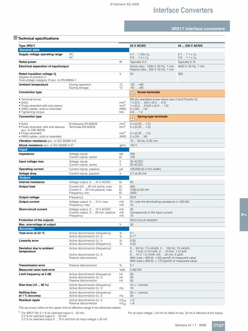
Interface Converters
7/157Siemens LV 1 T · 2009
3RS17 interface converters
7
■ Technical specifications
1) For 3RS17 06: 0.1 % for selected output 4... 20 mA; 0.3 % for selected output 0 ... 20 mA; 0.3 % for selected output 0 ... 10 V and from an input voltage > 50 mV.
For an input voltage < 50 mV an offset of max. 20 ms is effective at the output.
Type 3RS17 24 V AC/DC 24 ... 240 V AC/DCGeneral dataSupply voltage operating range DC 0.7 ... 1.25x Un 0.7 ... 1.1 x Un
AC 0.8 ... 1.2 x Un 0.8 ... 1.1 x Un
Rated power W Typically 0.3 Typically 0.75
Electrical separation of input/output Active disc.: 1500 V, 50 Hz, 1 min; Passive disc.: 500 V, 50 Hz, 1 min
4000 V, 50 Hz, 1 min
Rated insulation voltage Ui Degree of pollution 2 Overvoltage category III acc. to EN 60664-1
V 50 300
Ambient temperature During operation °C -25 ... +60During storage °C -40 ... +85
Connection type Screw terminals
• Terminal screw M3 (for standard screw driver size 2 and Pozidriv 2)• Solid mm2 1 x (0.5 ... 4)/2 x (0.5 ... 2.5)• Finely stranded with end sleeve mm2 1 x (0.5 ... 2.5)/2 x (0.5 ... 1.5)• AWG cables, solid or stranded AWG 2 x (20 ... 14)• Tightening torque Nm 0.8 … 1.2
Connection type Spring-type terminals
• Solid Enclosures EN 60529 mm2 2 x (0.25 ... 1.5)• Finely stranded, with end sleeves
acc. to DIN 46228Terminals EN 60529 mm2 2 x (0.25 ... 1.5)
• Finely stranded mm2 2 x (0.25 ... 1.5)• AWG cables, solid or stranded AWG 2 x (24 ... 16)
Vibration resistance acc. to IEC 60068-2-6 10 ... 55 Hz: 0.35 mm
Shock resistance acc. to IEC 60068-2-27 g/ms 15/11InputImpedance Voltage inputs kΩ 330
Current inputs, active Ω 100
Input voltage max. Voltage inputs V 30 AC/DCCurrent inputs, active V 30 AC/DC
Operating current Current inputs, passive µA 100/250 (6.2 mm width)
Voltage drop Current inputs, passive V 2.7 at 20 mAOutputInternal resistance Voltage output, 0 ... 10 V AC/DC Ω 55
Output load Current 0/4 ... 20 mA active, max. Ω 400Current 0 ... 20 mA passive, max. Ω 1000 at 20 mAFrequency, min. Ω 2400
Output voltage Frequency V 20.9
Output current Voltage output, 0 ... 10 V, max. mA 21; note the terminating resistance (> 500 Ω)! Frequency, max. mA 10
Short-circuit current Voltage output, 0 ... 10 V AC/DC mA 40Current output, 0 ... 20 mA, passive mA Corresponds to the input currentFrequency mA 15
Protection of the outputs Short-circuit resistant
Max. overvoltage at output V 30AccuracyTotal error at 23 °C Active disconnector (frequency) % 0.1
Active disconnector (U, I) % 0.11)
Linearity error Active disconnector (U, I) % 0.02Active disconnector (frequency) % 0.02
Deviation due to ambient temperature
Active disconnector (frequency) 0 ... 50 Hz: 7.5 mHz/K; 0 ... 100 Hz: 15 mHz/K; 0 ... 1 kHz: 0.15 Hz/K; 0 ... 10 kHz: 1.5 Hz/K
Active disconnector (U, I) 0 ... 10 V: 1.5 mV/K; 0/4 ... 20 mA: 3 µA/KPassive disconnector With load < 600 Ω: <100 ppm/K of measured value
With load ≥ 600 Ω: < 175 ppm/K of measured value
Transmission error Passive disconnector % 0.1
Measured value load error %/Ω 0.06/100
Limit frequency at 3 dB Active disconnector (frequency) Hz 30Active disconnector (U, I) Hz 30Passive disconnector Hz 50
Rise time (10 ... 90 %) Active disconnector (frequency) 10 + 1 periodActive disconnector (U, I) ms 10
Settling time at 1 % accuracy
Active disconnector (frequency) 30 + 1 periodActive disconnector (U, I) ms 30
Residual ripple Active disconnector (U, I) mVeff < 5 Passive disconnector mVeff < 8
The accuracy refers to the upper limit of effective range if not otherwise stated.
LV1T_2009_Gesamtbuch_EN.book Seite 157 Donnerstag, 26. Februar 2009 2:00 14
© Siemens AG 2009

Interface Converters
3RS17 interface converters
7/158 Siemens LV 1 T · 2009
7
■ Dimensional drawings
1) Depth for 3RS17 25 is approx. 90 mm.2) Dimensions for screw terminal.3) Dimensions for spring-type terminal.
■ Schematics
6.2 mm design 12.5 mm design 17.5 mm design
��
�
��
��
��
�
��
��
��
����
�
��
��
��
����
����
�
���
�
����
3RS17 00-..D.. 3RS17 02-..D.. 3RS17 03-..D. . 3RS17 05-..D.. 3RS17 06- . FD00
3RS17 06-.FE00 3RS17 0.-..W00
3RS17 25-.FD00 3RS17 25-.FW00
3RS17 20-.ET00 3RS17 21-.ET00
3RS17 22-.ET00
����
�������
��� ��
��� � ��
���
�
���
�
�
� �������������
��� ��
��� ���
��� �
�
� ���
����
����
� ����
�������������
��� ���
��� � ��
��� �
�
� ���
���� ����
� ����
����������
��� ���
��� � ��
��� �
�
� ���
����
� �
��������������
�������
��� ��
��� ���
��� �
�
� ���
����
����
� ����
�������������
��� ���
��� ���
��� �
�
� ���
���� ����
� ����
��������������
�
�
���� ���
���
���
����
����
�
�
��� ���
��� � ��
��� �
�
� ���
�
�
�
��
��� � ��
���
���
���
���
����
����
����
����
��
� �
������
� �
LV1T_2009_Gesamtbuch_EN.book Seite 158 Donnerstag, 26. Februar 2009 2:00 14
© Siemens AG 2009