Embed Size (px)
Citation preview
System Handbook for an STC UTC System 666/HE/16940/000
666-HE-16940-000.doc Issue 31 Page i
Siemens Mobility, Traffic Solutions Sopers Lane POOLE Dorset BH17 7ER SYSTEM/PROJECT/PRODUCT: STC UTC SYSTEM
SYSTEM HANDBOOK
for an
STC UTC SYSTEM
This is an unpublished work the copyright in which vests in Siemens plc. All rights reserved. The information contained herein is the property of Siemens plc and is supplied without liability for errors or omissions. No part may be reproduced or used except as authorised by contract or other written permission. The copyright and the foregoing restriction on reproduction and use extend to all the media in which this information may be embodied.
System Handbook for an STC UTC System 666/HE/16940/000
666-HE-16940-000.doc Issue 31 Page ii
ISSUE STATE
Note: Source of documents is shown under Type as below.
1=Paper, 2=VAX, 3=Microfilm, 4=CALTEXT Disc, 5=DECmate Disc,
6=Paper Insert, 7=MAC Disc, 8=LIFESPAN, 9=SUN, 10=AutoManager-Meridian.
The document comprises the following components:
Pages Issue Type Part ID File ID
All 31 10 666HE16940000 he16940_V30.doc
System Handbook for an STC UTC System 666/HE/16940/000
666-HE-16940-000.doc Issue 31 Page iii
CONTENTS
1. INTRODUCTION..................................................................................................9 1.1 Purpose ................................................................................................................................................9 1.2 Scope ....................................................................................................................................................9 1.3 Related Documents .............................................................................................................................9
1.3.1 Parent Documents ............................................................................................................................9 1.3.2 Kindred Documents .........................................................................................................................9
1.4 Definitions..........................................................................................................................................10 1.5 Issue State and Amendments ...........................................................................................................10
2. GENERAL..........................................................................................................12 2.1 System Overview...............................................................................................................................12 2.2 System Facilities ................................................................................................................................12 2.3 Configurable Facilities......................................................................................................................12
2.3.1 UTC Facilities ................................................................................................................................13 2.3.2 SCOOT Facilities ...........................................................................................................................13 2.3.3 Links to External Facilities ............................................................................................................13
3. EQUIPMENT IDENTIFICATION ........................................................................14 3.1 Identifying single items of equipment .............................................................................................14
3.1.1 UTC Equipment .............................................................................................................................14 3.1.2 SCOOT Equipment Identification..................................................................................................15
3.2 Referring to sets of equipment.........................................................................................................16 3.2.1 UTC Equipment .............................................................................................................................16 3.2.2 SCOOT Equipment ........................................................................................................................16
4. SYSTEM CONTROL AND CONFIGURATION ..................................................18 4.1 UTC System Start Up .......................................................................................................................18 4.2 UTC System Time.............................................................................................................................18 4.3 UTC System Capacity ......................................................................................................................18 4.4 Timetables..........................................................................................................................................19
4.4.1 Introduction....................................................................................................................................19 4.4.2 Date-of-year Timetable ..................................................................................................................19 4.4.3 Day-of-week Timetable .................................................................................................................19 4.4.4 Time-of-day Timetables.................................................................................................................19 4.4.5 Timetable substitution ....................................................................................................................20 4.4.6 Timetable summary........................................................................................................................20
4.5 CASTs (Commands Actioned and Stored Together).....................................................................20 4.5.1 Introduction....................................................................................................................................20 4.5.2 Multi-computer Operation .............................................................................................................20 4.5.3 Available Commands .....................................................................................................................20
4.6 Command Journal ............................................................................................................................21 4.6.1 Introduction....................................................................................................................................21 4.6.2 The Journal Optimisation Process..................................................................................................21 4.6.3 Multi-computer Operation .............................................................................................................21 4.6.4 Facilities Available.........................................................................................................................21
4.7 Fault Detection and Notification......................................................................................................21 4.7.1 Introduction....................................................................................................................................21
4.8 Fault Category Groups.....................................................................................................................22
System Handbook for an STC UTC System 666/HE/16940/000
666-HE-16940-000.doc Issue 31 Page iv
4.8.1 Fault Recognition ...........................................................................................................................22 4.8.2 System Response to Faults.............................................................................................................22
4.9 Software Integrity Faults .................................................................................................................23 4.10 Terminal Faults.................................................................................................................................23 4.11 Operator Fault Clearance ................................................................................................................23 4.12 Data Transmission Faults.................................................................................................................23 4.13 System Log.........................................................................................................................................24 4.14 Extended Logging .............................................................................................................................24 4.15 System Re-Starts ...............................................................................................................................24
5. OPERATOR FACILITIES...................................................................................25 5.1 Operator Command Entry...............................................................................................................25
5.1.1 Introduction....................................................................................................................................25 5.1.2 Expert Command Entry..................................................................................................................26 5.1.3 Novice Command Entry.................................................................................................................26 5.1.4 On-line Command Help .................................................................................................................26 5.1.5 Available Commands .....................................................................................................................26 5.1.6 Terminal Characteristics ................................................................................................................26
5.2 Command Line Editing ....................................................................................................................27 5.3 Access Control By Password............................................................................................................27 5.4 Dial-Up Access...................................................................................................................................28 5.5 Wall Map ...........................................................................................................................................28 5.6 System Indication Panel (SIP) .........................................................................................................29
6. DATA ENTRY ....................................................................................................30 6.1 Data Preparation...............................................................................................................................30
6.1.1 Introduction....................................................................................................................................30 6.1.2 The Process ....................................................................................................................................30 6.1.3 UTC and SCOOT data ...................................................................................................................30 6.1.4 Terminal and User Data .................................................................................................................31 6.1.5 Messages ........................................................................................................................................31 6.1.6 Foreign Language Messages and Dictionaries...............................................................................31
6.2 Plan Data ...........................................................................................................................................31 6.3 Timetable Data..................................................................................................................................31 6.4 Baseline Data .....................................................................................................................................31
7. JUNCTION AND PELICAN CONTROL AND MONITORING ............................33 7.1 Junction Interface .............................................................................................................................33
7.1.1 Introduction....................................................................................................................................33 7.1.2 Junction Control Bits......................................................................................................................33 7.1.3 Junction Reply Bits ........................................................................................................................36
7.2 Pelican Interface ...............................................................................................................................40 7.2.1 Pelican Control Bits .......................................................................................................................40 7.2.2 Pelican Reply Bits ..........................................................................................................................40
7.3 Master Cycle Counter ......................................................................................................................42 7.4 Relative Priority of Control Methods .............................................................................................42 7.5 Signal Co-ordination by Fixed Time Plans.....................................................................................42
7.5.1 Introduction....................................................................................................................................42 7.5.2 Fixed time plans .............................................................................................................................43
System Handbook for an STC UTC System 666/HE/16940/000
666-HE-16940-000.doc Issue 31 Page v
7.5.3 Local Plan ......................................................................................................................................43 7.5.4 Preparing the data...........................................................................................................................43 7.5.5 Temporary Amendments................................................................................................................44
7.6 Green Waves .....................................................................................................................................44 7.6.1 Introduction....................................................................................................................................44 7.6.2 Defining the route ..........................................................................................................................44 7.6.3 Starting a Green Wave ...................................................................................................................45 7.6.4 Primed Green Wave .......................................................................................................................45
7.7 Manual Waves...................................................................................................................................45 7.8 Manual Hurry Call ...........................................................................................................................46 7.9 VIP Routes.........................................................................................................................................46 7.10 Automatic Plan Selection (APS) ......................................................................................................46
7.10.1 Introduction ...............................................................................................................................46 7.10.2 Detector States...........................................................................................................................47 7.10.3 Group States ..............................................................................................................................47 7.10.4 Plan Selection ............................................................................................................................47 7.10.5 Plan Priority...............................................................................................................................47 7.10.6 Actioning of CASTS by APS....................................................................................................47
7.11 Signal Co-ordination by SCOOT ....................................................................................................47 7.12 SCOOT Translation Plans ...............................................................................................................48 7.13 Plan Compliance Faults....................................................................................................................48
7.13.1 Introduction ...............................................................................................................................48 7.13.2 Intersection Controller Continuous Checks...............................................................................49 7.13.3 Under Fixed Time Control ........................................................................................................49 7.13.4 Under Local Control..................................................................................................................49 7.13.5 Pedestrian Controller Checks ....................................................................................................49 7.13.6 Intersection permanent demand checking: ................................................................................50
7.14 Controller Checks .............................................................................................................................50 7.14.1 Introduction ...............................................................................................................................50 7.14.2 Timing of checks .......................................................................................................................50 7.14.3 Interruption by higher priority...................................................................................................50 7.14.4 Duration of Individual Tests......................................................................................................51 7.14.5 Potential Problems.....................................................................................................................51 7.14.6 Data that is Checked..................................................................................................................51
7.15 Link Lists ...........................................................................................................................................52
8. OTHER STREET EQUIPMENT INTERFACE ....................................................53 8.1 Special Control Facility ....................................................................................................................53 8.2 Remote Request Facility...................................................................................................................53 8.3 Collection of Traffic Data.................................................................................................................53 8.4 Congestion Detection ........................................................................................................................54
8.4.1 Introduction....................................................................................................................................54 8.4.2 Queue Congestion ..........................................................................................................................54 8.4.3 Occupancy Congestion...................................................................................................................54
8.5 Car Park Information System .........................................................................................................55 8.5.1 Introduction....................................................................................................................................55 8.5.2 Operator Control ............................................................................................................................55 8.5.3 Car Park States ...............................................................................................................................55 8.5.4 Car Park Occupancy.......................................................................................................................56 8.5.5 Car Park Occupancy Predictions ..................................................................................................56 8.5.6 Car Park Groups.............................................................................................................................56 8.5.7 On-Street Parking...........................................................................................................................57
System Handbook for an STC UTC System 666/HE/16940/000
666-HE-16940-000.doc Issue 31 Page vi
8.5.8 Car Park Signs................................................................................................................................57 8.5.9 System start-up...............................................................................................................................58 8.5.10 Transfer of Car Park Data to a Variable Message Sign Control System (VCS) .......................58
8.6 Diversion Control System.................................................................................................................58 8.6.1 Introduction....................................................................................................................................58 8.6.2 Groups and Types ..........................................................................................................................58 8.6.3 Ripple Diversion ............................................................................................................................59 8.6.4 Diversion States .............................................................................................................................59 8.6.5 Diversion signs...............................................................................................................................59 8.6.6 Diversion plans ..............................................................................................................................59 8.6.7 Operational.....................................................................................................................................60
8.7 Tidal/Tunnel Flow System ...............................................................................................................60 8.7.1 Introduction....................................................................................................................................60 8.7.2 Tidal Flow Signalling.....................................................................................................................61 8.7.3 Operator Control ............................................................................................................................61
8.8 SCOOT Detector Faults ...................................................................................................................61 8.9 Other Equipment Faults...................................................................................................................61 8.10 Variable Message Signs (VMS)........................................................................................................62 8.11 Analogue Sensor Interface ...............................................................................................................62 8.12 Link Travel Time ..............................................................................................................................62 8.13 Tram Interface ..................................................................................................................................62
9. DISPLAY, STATUS AND OUTPUTS.................................................................64 9.1 Introduction.......................................................................................................................................64 9.2 Monochrome Screen Displays..........................................................................................................64
9.2.1 Introduction....................................................................................................................................64 9.2.2 Control and Reply Bit Monitor ......................................................................................................64 9.2.3 Control and Reply Bit Monitor, with override...............................................................................64 9.2.4 Control Status Monitor...................................................................................................................64 9.2.5 Detector Flow Displays..................................................................................................................65 9.2.6 Validation Displays........................................................................................................................65 9.2.7 SCOOT Parameter Display ............................................................................................................65 9.2.8 System Data Display ......................................................................................................................65 9.2.9 Daily Flow Display ........................................................................................................................65 9.2.10 Weekly Flow Display................................................................................................................65
9.3 Colour Graphic Displays (Non Windows) ......................................................................................65 9.3.1 Introduction....................................................................................................................................65 9.3.2 User definable pictures...................................................................................................................65 9.3.3 VEGA diagram ..............................................................................................................................66 9.3.4 Time and Distance diagram............................................................................................................66
9.4 Graphical User Interface (GUI) Displays .......................................................................................66 9.4.1 Introduction....................................................................................................................................66 9.4.2 Iconising of Windows ....................................................................................................................66 9.4.3 UTC Window.................................................................................................................................66 9.4.4 Colour displays ..............................................................................................................................66
9.5 Screen Dumps to Printer ..................................................................................................................67 9.6 Listings...............................................................................................................................................68 9.7 Log OTU Replies to Disc ..................................................................................................................68 9.8 Event Driven Messages.....................................................................................................................68 9.9 User Information Messages..............................................................................................................68
System Handbook for an STC UTC System 666/HE/16940/000
666-HE-16940-000.doc Issue 31 Page vii
10. DATA FILE MANAGEMENT ..........................................................................70 10.1 Off line Data File Storage.................................................................................................................70 10.2 Data Transfer to a PC ......................................................................................................................70 10.3 Shareable Data Directory.................................................................................................................70
10.3.1 OTU Log Files in ASCII Format...............................................................................................71
11. UTC SYSTEM WITH NETWORKED COMPUTERS ......................................72 11.1 Traffic Management Computer.......................................................................................................72 11.2 Traffic Control Computers ..............................................................................................................72 11.3 Combined Management and Control Computer ...........................................................................72 11.4 Connectivity.......................................................................................................................................72
12. UTMC COMMON DATA BASE......................................................................73 12.1 Introduction.......................................................................................................................................73
13. USER ACCESS THROUGH A TERMINAL SERVER ....................................74 13.1 Terminal Interface ............................................................................................................................74 13.2 The User Interface ............................................................................................................................74 13.3 The Terminal Configuration Process..............................................................................................74
14. HARDWARE...................................................................................................75 14.1 Introduction.......................................................................................................................................75 14.2 Instation Equipment .........................................................................................................................75
14.2.1 Introduction ...............................................................................................................................75 14.2.2 Traffic Computer.......................................................................................................................75 14.2.3 System Modem..........................................................................................................................75 14.2.4 Hard Copy Printer .....................................................................................................................75 14.2.5 Monochrome VDU terminal...................................................... Error! Bookmark not defined. 14.2.6 PC Workstation (Non Windows) .............................................. Error! Bookmark not defined. 14.2.7 PC Workstation (GUI) ..............................................................................................................75 14.2.8 System Indication Panel ............................................................................................................75 14.2.9 Wall Map...................................................................................................................................76 14.2.10 Data Transmission Equipment ..................................................................................................76 14.2.11 UTC System Cubicle(s).............................................................................................................76 14.2.12 Terminal Server.........................................................................................................................76 14.2.13 Roving Terminal........................................................................................................................76
14.3 Outstation Equipment ......................................................................................................................77 14.3.1 Introduction ...............................................................................................................................77 14.3.2 Outstation Data Transmission Equipment.................................................................................77 14.3.3 Traffic Controllers.....................................................................................................................77 14.3.4 Signs ..........................................................................................................................................77 14.3.5 Traffic Detectors........................................................................................................................77 14.3.6 Green Wave Route Selection Boxes..........................................................................................77
15. SOFTWARE ...................................................................................................79 15.1 Introduction.......................................................................................................................................79 15.2 STC Supplied Software ....................................................................................................................79 15.3 Computer Manufacturers' Software...............................................................................................79
16. SYSTEM INTERFACES .................................................................................80 16.1 Introduction.......................................................................................................................................80
System Handbook for an STC UTC System 666/HE/16940/000
666-HE-16940-000.doc Issue 31 Page viii
16.2 Street Equipment Interface..............................................................................................................80 16.3 Operator Interface............................................................................................................................80 16.4 STC Remote Monitoring System (RMS) Link ...............................................................................80 16.5 Motorway Control System Link ......................................................................................................80
16.5.1 UTC to NMCS interface............................................................................................................81 16.5.2 NMCS to UTC interface............................................................................................................81
16.6 Environmental Monitoring Interface..............................................................................................81 16.7 Foreign Language Interface.............................................................................................................81 16.8 ITMC System Interface....................................................................................................................81 16.9 ASTRID Interface.............................................................................................................................81 16.10 On-street Parking Interface .............................................................................................................82 16.11 Upload / Download of Controller Data ...........................................................................................82 16.12 External Time Source .......................................................................................................................83 16.13 Time Display Clock Interface ..........................................................................................................83 16.14 Transfer of Link Travel Times to PC..............................................................................................83 16.15 SIESPACE Car Parking System Interface.....................................................................................83 16.16 Travel Terminal Interface................................................................................................................83 16.17 ALFIA Systems Car Parking Interface ..........................................................................................83 16.18 Car Park Variable Message Sign System .......................................................................................83 16.19 Web Server Interface........................................................................................................................84 16.20 Link to STC Fault Management System PREFECT.....................................................................84 16.21 Link to Other Host Computers........................................................................................................84
APPENDIX A - SUMMARY OF SYSTEM COMMANDS .......................................85
APPENDIX B - VALU AND CHAN PARAMETERS ..............................................93
APPENDIX C - FAULT AND ADVICE DETAILS.................................................102
APPENDIX D - UTC SYSTEM CAPACITY..........................................................114
APPENDIX E - OPEN SOURCE SOFTWARE COPYRIGHT / LICENSE DECLARATIONS 117
INDEX......................................................................................................................130
System Handbook for an STC UTC System 666/HE/16940/000
666-HE-16940-000.doc Issue 31 Page 9
1. INTRODUCTION
1.1 Purpose
This document describes the Siemens (STC) Urban Traffic Control (UTC) System (including SCOOT) specified in the System Requirements Specification for an STC UTC System. See Reference 1.3.1(a). It is intended as an introduction to the UTC System facilities for day to day users of the System.
1.2 Scope
The scope of this document is limited to the standard STC UTC System plus a number of additional facilities available under licence (see section 2.3). In this context "standard" means that which is supplied by STC with no customer specific tailoring. That is, the facilities described are available at no extra cost unless specifically designated as licensed.
The document assumes that the reader has some basic Traffic Engineering knowledge, including knowledge about phases, stages, sub-areas, nodes, etc.
1.3 Related Documents
1.3.1 Parent Documents
1.3.1(a) 666/UH/16940/000 System Requirements Specification for an STC UTC System
1.3.2 Kindred Documents
1.3.2(a) 666/KE/16066/000 UTC Glossary of terms 1.3.2(b) 666/UH/16940/xxx1 Customer Requirements Specification 1.3.2(c) 666/HB/16940/000 Operator handbook for an STC UTC System 1.3.2(d) 666/HD/16940/000 Data preparation handbook for an STC UTC System 1.3.2(e) 666/HF/16940/000 SCOOT User Guide 1.3.2(f) 666/HG/16940/000 System Management Guide for an STC UTC System 1.3.2(g) 666/HH/16940/000 Data Preparation Guide for an STC UTC System 1.3.2(h) 666/HI/16940/000 Data File Format Guide for an STC UTC System 1.3.2(i) 666/HK/16940/000 User Guide for the STC UTC System Roving Terminal 1.3.2(j) 666/HB/16101/003 SCOOT Traffic Handbook V4.2 (supplied under licence)
1.3.2(k) TR 0141A Microprocessor Based Traffic Signal Controller for Isolated, Linked and Urban Traffic Control Installations
1.3.2(l) 666/HP/16940/000 Plan Preparation Handbook for an STC UTC System 1.3.2(m) 666/HT/16940/000 Timetable Preparation Handbook for an STC UTC System
1 The 'xxx' in this reference replaces the 3-digit number that uniquely identifies a particular UTC System. That is, the customer variant for the Customer Requirements Specification.
System Handbook for an STC UTC System 666/HE/16940/000
666-HE-16940-000.doc Issue 31 Page 10
1.3.2(n) TS004.003.2007 UTMC Objects Registry (http://www.utmc.uk.com/technical/04.html
1.4 Definitions
For all definitions and abbreviations used in this and related UTC documentation see the UTC Glossary of terms (reference 1.3.2(a)).
However, throughout this document the convention has been applied that 'System' means the UTC System and that 'system' applies to other things such as data transmission systems, computer operating systems etc.
Please note that throughout the document a number of ranges, or specific values, are mentioned. The following convention has been used in order to simplify the text. Immediately after each value, or range, a special character string indicates the requirement for modifying the value. These strings, and their interpretation, are as follows:
(U) the value is user configurable
(B) the value is modifiable only by STC during system build, if a value different from the value specified in this document is required. This value is recorded in the Customer Requirements Specification, Reference 1.3.1(a)
(S) the value is configurable by STC
(M) the value is not configurable.
1.5 Issue State and Amendments
Issue 1.1A First draft for review
Issue 1.1B Revised after issue of System Requirement Specification
Issue 1.1C Revision after engineering comments
Issue 01.00D Revision after second set of comments prior to review
Issue 01.00 Revised after engineering review
Issue 02 to 06 Not Issued
Issue 07.00 DC 9338, 10-SEP-93. Minor amendments and issue state now reflects Software issue state
Issue 08.00 New facilities added and amendments
Issue 09.00 Revised following update of SRS (DC12554 refers)
Issue 10.00 Revised and updated to reflect V10 software
Issue 11.00 Not issued
Issue 12.00 Revised and updated to reflect V12 software
Issue 13.00 and 14.00 Not issued
Issue 15.00 Revised and updated to reflect Version 15 software
System Handbook for an STC UTC System 666/HE/16940/000
666-HE-16940-000.doc Issue 31 Page 11
Issue 16 Not issued
Issue 17 Revised and updated to reflect Version 17 software
Issues 18 to 20 Not issued
Issue 21 Revised and updated to reflect Version 21 software
Issues 22 Not issued
Issue 23 Revised and updated to reflect Version 23 software.
Added description of Primed green wave.
Issues 24 to 27 Not issued
Issue 28 Revised and updated to reflect Version 28 software
Issue 29 Not issued
Issue 30 Add appendix for external copyright declarations, and update appendices.
Issue 31 Remove references to VAX, Alpha and make hardware neutral
System Handbook for an STC UTC System 666/HE/16940/000
666-HE-16940-000.doc Issue 31 Page 12
2. GENERAL
2.1 System Overview
UTC Systems were originally designed to provide a central control and monitoring point for junction and pedestrian controllers. The System provided a means of easily varying the stage timings without having to make wiring changes to each controller. As a consequence traffic authorities obtained a facility which allowed them to respond to special events. The monitoring facilities of the System meant that maintenance effort could be directed at more immediate problems, whilst also providing more information about the problem. Over the years the System has developed to include a wide variety of facilities, such as car park control, diversions, green waves and SCOOT.
Physically the System comprises two main parts connected by either 2 and/or 4 wire circuits that are normally supplied by the local telephone company. The two parts are:
(a) Instation equipment (the computer equipment, UTC System software, terminals and instation data transmission equipment), located in the control centre.
(b) Outstation equipment comprising Outstation Transmission Units (OTUs) connected to signal controllers, traffic detectors, etc. on the street.
The terminals used to control the System normally comprise a mixture of hard-copy terminals, monochrome VDUs, PC and GUI2 workstations, which may be located at the Control Centre or remotely as required. A 'roving' terminal to assist in SCOOT validation may also be supplied. This allows an engineer on the street to communicate with the System by a radio link.
The STC data transmission system comprises the instation equipment in (a) and OTUs in (b) above and is used for communication between the computer(s) and the on-street equipment.
2.2 System Facilities
The sections that follow describe the facilities of the standard STC UTC System. Where possible, main sections of this document have the same title as sections of the Systems Requirement Specification (reference 1.3.1(a)). Thus section 3 in this document relates to section 3 in the Systems Requirement Specification, both sections having the title "Equipment Identification". Where applicable this relationship is also maintained between sub-sections of this document and sub-sections of the Systems Requirement Specification.
2.3 Configurable Facilities
The following facilities are configurable items and may be subject to additional charges. For more details contact STC.
2 Graphical User Interface. These terminals use a Windows, mouse and icon-based interface.
System Handbook for an STC UTC System 666/HE/16940/000
666-HE-16940-000.doc Issue 31 Page 13
2.3.1 UTC Facilities
Windows-based Graphical User Interface (GUI).................see section 9.4
Multiple demand dependent stages ......................................see section 7.1.2(1)
Gap Out ................................................................................see section 7.1.2(10)
Extended logging..................................................................see section 4.14
LF3 lamp fault support .........................................................see section 7.1.3(14)
Upload / download of controller data...................................see section 16.11
Foreign language support .....................................................see section 16.7
Detector Histogram Displays ...............................................see section 9.4.4(4)
Message Sign Control ..........................................................see section 8.8
2.3.2 SCOOT Facilities
SCOOT.................................................................................see section 7.11
Storage of event driven messages to disc.............................see section 9.8
Multiple removable SCOOT stages .....................................see reference 1.3.2(e)
Changing SCOOT maximum and minimum stage lengths ..see reference 1.3.2(e)
Link travel time collection ...................................................see reference 1.3.2(e)
2.3.3 Links to External Facilities
RMS (Remote Monitoring System) .....................................see section 16.4
NMCS (Motorway Control System) ....................................see section 16.5
ITMC Interface.....................................................................see section 16.8
ASTRID................................................................................see section 16.9
Analogue Sensor interface ..................................................see section 16.6
System Handbook for an STC UTC System 666/HE/16940/000
666-HE-16940-000.doc Issue 31 Page 14
3. EQUIPMENT IDENTIFICATION
3.1 Identifying single items of equipment
3.1.1 UTC Equipment
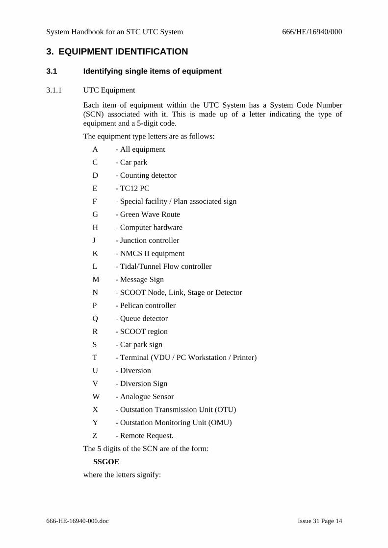
Each item of equipment within the UTC System has a System Code Number (SCN) associated with it. This is made up of a letter indicating the type of equipment and a 5-digit code.
The equipment type letters are as follows:
A - All equipment
C - Car park
D - Counting detector
E - TC12 PC
F - Special facility / Plan associated sign
G - Green Wave Route
H - Computer hardware
J - Junction controller
K - NMCS II equipment
L - Tidal/Tunnel Flow controller
M - Message Sign
N - SCOOT Node, Link, Stage or Detector
P - Pelican controller
Q - Queue detector
R - SCOOT region
S - Car park sign
T - Terminal (VDU / PC Workstation / Printer)
U - Diversion
V - Diversion Sign
W - Analogue Sensor
X - Outstation Transmission Unit (OTU)
Y - Outstation Monitoring Unit (OMU)
Z - Remote Request.
The 5 digits of the SCN are of the form:
SSGOE
where the letters signify:
System Handbook for an STC UTC System 666/HE/16940/000
666-HE-16940-000.doc Issue 31 Page 15
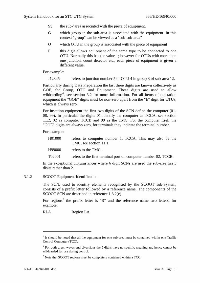
SS the sub-3area associated with the piece of equipment.
G which group in the sub-area is associated with the equipment. In this context "group" can be viewed as a "sub-sub-area"
O which OTU in the group is associated with the piece of equipment
E this digit allows equipment of the same type to be connected to one OTU. Normally this has the value 1; however for OTUs with more than one junction, count detector etc., each piece of equipment is given a different value.
For example:
J12345 refers to junction number 5 of OTU 4 in group 3 of sub-area 12.
Particularly during Data Preparation the last three digits are known collectively as GOE, for Group, OTU and Equipment. These digits are used to allow wildcarding4, see section 3.2 for more information. For all items of outstation equipment the "GOE" digits must be non-zero apart from the "E" digit for OTUs, which is always zero.
For instation equipment the first two digits of the SCN define the computer (01-08, 99). In particular the digits 01 identify the computer as TCCA, see section 11.2, 02 as computer TCCB and 99 as the TMC. For the computer itself the "GOE" digits are always zero, for terminals they indicate the terminal number.
For example:
H01000 refers to computer number 1, TCCA. This may also be the TMC, see section 11.1.
H99000 refers to the TMC.
T02001 refers to the first terminal port on computer number 02, TCCB.
In the exceptional circumstances where 6 digit SCNs are used the sub-area has 3 disits rather than 2.
3.1.2 SCOOT Equipment Identification
The SCN, used to identify elements recognised by the SCOOT sub-System, consists of a prefix letter followed by a reference name. The components of the SCOOT SCN are described in reference 1.3.2(e).
For regions5 the prefix letter is "R" and the reference name two letters, for example:
RLA Region LA
3 It should be noted that all the equipment for one sub-area must be contained within one Traffic Control Computer (TCC). 4 For both green waves and diversions the 5 digits have no specific meaning and hence cannot be wildcarded for use during control. 5 Note that SCOOT regions must be completely contained within a TCC.
System Handbook for an STC UTC System 666/HE/16940/000
666-HE-16940-000.doc Issue 31 Page 16
For all other elements the prefix letter is "N", for node. The reference name then consists of 5 digits6 followed by a suffix indicating the type and identity of the equipment. For example:
N30111 Node 30111
N30111D Link D on node 30111
N30111D2 Detector 2 on link D on node 30111
N30111/3 SCOOT Stage 3 on node 30111
From this it can be seen that a node SCN followed by a single letter indicates a link, a link SCN followed by a single digit indicates a detector and a node SCN followed by a "/" and a single digit a SCOOT stage.
3.2 Referring to sets of equipment
3.2.1 UTC Equipment
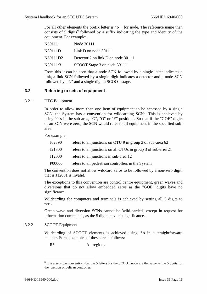
In order to allow more than one item of equipment to be accessed by a single SCN, the System has a convention for wildcarding SCNs. This is achieved by using "0"s in the sub-area, "G", "O" or "E" positions. So that if the "GOE" digits of an SCN were zero, the SCN would refer to all equipment in the specified sub-area.
For example:
J62390 refers to all junctions on OTU 9 in group 3 of sub-area 62
J21300 refers to all junctions on all OTUs in group 3 of sub-area 21
J12000 refers to all junctions in sub-area 12
P00000 refers to all pedestrian controllers in the System
The convention does not allow wildcard zeros to be followed by a non-zero digit, that is J12001 is invalid.
The exceptions to this convention are control centre equipment, green waves and diversions that do not allow embedded zeros as the "GOE" digits have no significance.
Wildcarding for computers and terminals is achieved by setting all 5 digits to zero.
Green wave and diversion SCNs cannot be 'wild-carded', except in request for information commands, as the 5 digits have no significance.
3.2.2 SCOOT Equipment
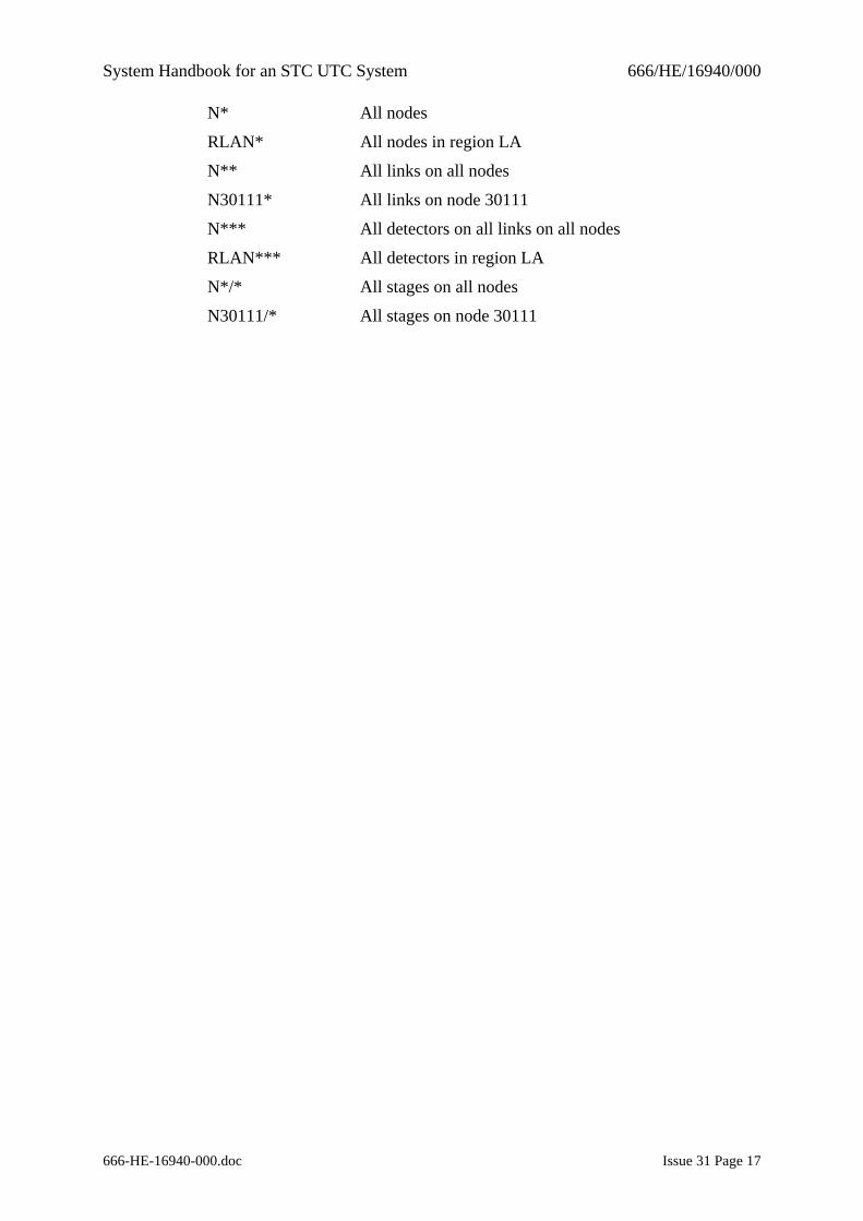
Wildcarding of SCOOT elements is achieved using '*'s in a straightforward manner. Some examples of these are as follows:
R* All regions
6 It is a sensible convention that the 5 letters for the SCOOT node are the same as the 5 digits for the junction or pelican controller.
System Handbook for an STC UTC System 666/HE/16940/000
666-HE-16940-000.doc Issue 31 Page 17
N* All nodes
RLAN* All nodes in region LA
N** All links on all nodes
N30111* All links on node 30111
N*** All detectors on all links on all nodes
RLAN*** All detectors in region LA
N*/* All stages on all nodes
N30111/* All stages on node 30111
System Handbook for an STC UTC System 666/HE/16940/000
666-HE-16940-000.doc Issue 31 Page 18
4. SYSTEM CONTROL AND CONFIGURATION
4.1 UTC System Start Up
Normally the System starts automatically after a power failure. However, if necessary, the computer(s) has (have) a restart button on the front panel which when pressed and released automatically starts the System. More details can be found in the System Management Guide (reference 1.3.2(f)).
On start-up the computer(s) require to know the time and date. Operator intervention is only required if this is the first, or only, computer to start and its battery backed clock has failed. In this case the System prompts the operator for the time and date.
In a multi-computer System when a TCC restarts its data is compared to the data in the TMC. If it is different then a new set of data is downloaded from the TMC. When the TMC restarts it compares the TCC(s) data with its own and if different a warning7 is issued.
4.2 UTC System Time
The UTC System computer is provided with a clock unit to store the time and date and, by use of its battery, maintains this data through periods when the computer is powered off. The unit is used at System start-up as the source of the current time and date - see section 4.1.
During normal System operation, the time and date is maintained within the software. At System start up this is synchronised to the time and date obtained from the system clock. Thereafter the software time and date is not synchronised to the system clock although it is compared with it every minute and any significant discrepancy reported as a fault. All time-dependent functions within the System use the time and date stored in the software as a reference.
If the System is configured to accept the synchronisation date from an external source (see section 16.12) and such data is available at start up, then the external source time and date are used to set the System's date and time.
The System also provides a facility for automatically moving the clock forward and backward once per year for daylight saving, known as Daylight Saving Time (DST). The dates are user configurable and are described in the Data Preparation Handbook (reference 1.3.2(d)).
In a multi-computer System the TCC(s) take their initial time from the TMC. If this is not available then the TCC takes its time from the TCC with the lowest SCN.
4.3 UTC System Capacity
The amount of equipment that a single UTC computer can control or monitor is given in Appendix D and the Customer Requirement Specification (reference 1.3.2(b)).
7 The TCCs are not automatically updated to avoid the TCCs being restarted in the middle of a peak period when the TMC is restarted.
System Handbook for an STC UTC System 666/HE/16940/000
666-HE-16940-000.doc Issue 31 Page 19
4.4 Timetables
4.4.1 Introduction
The Timetable facility makes it possible for the operator to schedule events to occur automatically at some time in the future. The events are implementations of commands that can be set up to occur without the operator's presence. However, fixed time plans selected by timetable do not have the same force as a command entered by an operator, see section 7.4. The times at which the events are to take place are set up and stored in the System timetables as part of System data preparation - see section 6.
Two types of timetables are available on the System:
date-of-year
day-of-week
These are described below. Further descriptions of the content of each type of timetable can be seen in reference 1.3.2(h).
4.4.2 Date-of-year Timetable
Only one date-of-year timetable is allowed and it is used to define dates in the year when a particular time-of-day timetable is to be used. The date-of-year timetable takes precedence over the day-of-week timetable.
4.4.3 Day-of-week Timetable
Again, only one day-of-week timetable is allowed and it is used to define which of the time-of-day timetables are to be used on a particular day of the week.
Within the UTC System, the date-of-year and day-of-week timetables are combined into a single timetable.
If at System start up there are no entries in the day-of-week or date-of-year timetables for the current day, the System leaves all equipment under local control and only implements operator commands.
4.4.4 Time-of-day Timetables
The System provides a number of timetables that may be either used on a day-of-week or date-of-year basis.
The time of day timetable defines the time at which particular events are to occur during a 24-hour period. The action times for the events can be specified to the nearest second. The event is performed on or as soon after the action time as processing allows. The events are defined in a similar way to operator commands, although the parameters may not be identical. See the Operator Handbook (reference 1.3.2(c)) and the Timetable Preparation Handbook (reference 1.3.2(m)) for more information. The commands that are available for action by the timetable are defined in Error! Reference source not found.. The System allows a number of such "time-of-day" timetables to be set up. Usually a System contains one timetable for the weekdays, one for the weekend and others for special occasions such as public holidays, carnivals, sports events, etc.
System Handbook for an STC UTC System 666/HE/16940/000
666-HE-16940-000.doc Issue 31 Page 20
The time-of-day timetable entries may be preceded by a day-of-week, to indicate that command will only be actioned on the particular day of the week, or by a date, to indicate that that command will only be actioned on that date (a "single shot" event).
4.4.5 Timetable substitution
An operator command permits the substitution of the current timetable with another valid timetable. The substituted timetable continues in operation until midnight or until superseded by another substituted timetable.
Selecting a new timetable causes an entry to be made in the System Log.
4.4.6 Timetable summary
The use of an additional, option, parameter may be used to produce a summary of all the timetabled commands which affect a single junction or pelican controller during the course of a week.
4.5 CASTs (Commands Actioned and Stored Together)
4.5.1 Introduction
The CAST facility allows the user to configure a set of commands so that they can all be invoked by a single timetable entry or operator command. Typically CASTs are used to change SCOOT default stage lengths and translation plans, or to modify the System for a special occasion.
The operator can add and remove commands in a CAST or obtain a list of the commands in a CAST. CASTs can be referred to either by their number or user definable name. Commands removed from a CAST are (S) listed in the System Log.
The operator can associate 3 CASTs with a Remote Request. The first CAST is actioned when the Remote Request is asserted, the second CAST when the Remote Request clears and the third CAST a user-definable time after clearance of the Remote Request.
The operator can associate a CAST with a SCOOT region, such that when the cycle time of that region passes through a particular cycle time, either rising or falling, a CAST is actioned. Alternatively, this facility can be set to run in a “test” mode whereby a message is output rather than the CAST being actioned.
4.5.2 Multi-computer Operation
In this type of System the TMC must be available for CASTs to be changed. Once a change has been made the TCC(s) are updated with the revised data. The TCC computers are also updated from the TMC when they restart.
4.5.3 Available Commands
The commands available within a CAST are restricted to those shown in Error! Reference source not found.. The commands within each CAST are actioned in
System Handbook for an STC UTC System 666/HE/16940/000
666-HE-16940-000.doc Issue 31 Page 21
sequence immediately following the timetable or operator request to action the CAST.
4.6 Command Journal
4.6.1 Introduction
The Command Journal is created by storing selected commands from the operator and the timetable. It forms a record of the current control state and is used when the System restarts, to re-impose the previous command state. As the journal cannot be infinite in size it is compressed daily and on System start-up by the journal optimiser.
On System restart the journal is optimised and the commands in the journal executed. If the time of the last command in the journal is for a different day the timetable for that day is run from the last time in the journal until midnight of that day, and then the timetable for the current day is run from midnight until the current time. If the last time in the journal is in the current day then the timetable is run from the last time in the journal until the current time.
4.6.2 The Journal Optimisation Process
Only commands entered before the optimisation system started are processed. The commands are scanned and any that result in no change to the System state are removed. Any commands added after the process started are then appended to the new journal before the process stops.
4.6.3 Multi-computer Operation
Each computer, whether TCC or TMC, holds its own local journal file.
4.6.4 Facilities Available
It is possible to list the journal on an operator's terminal. The optimised commands are listed first, followed by the commands entered after optimisation.
The journal is cleared when the System data is updated or when requested by operator command.
A list of commands that are journalled is given in Error! Reference source not found..
4.7 Fault Detection and Notification
4.7.1 Introduction
The System provides facilities for detecting faults in both its own operation and that of the on-street equipment to which it is connected. These facilities provide a defined response to the detection of each fault type. The fault types covered by this facility include:
Software Integrity section 4.9
Terminal section 4.10
System Handbook for an STC UTC System 666/HE/16940/000
666-HE-16940-000.doc Issue 31 Page 22
Data Transmission section 4.12
Plan Compliance section 7.13
SCOOT Detector section 8.8
Other on-street equipment section 8.9
4.8 Fault Category Groups
The System allows the fault categories given in 16.21Appendix C - to be gathered together in groups. The fault categories contained within a group may be specified in either an inclusive or exclusive way. Fault category groups are identified by four digit numbers. Fault category group numbers may be used in fault llisting commands.
4.8.1 Fault Recognition
The System looks for the faults described in the following sections by checking the equipment's status of the following:
(1) Reply data provided by the data transmission system is analysed for its own faults plus plan compliance, controller and SCOOT detector faults
(2) Status data associated with computer terminals and disc drives is analysed
(3) A status word set up by the System's own software is monitored to show its correct operation.
4.8.2 System Response to Faults
The detection of each new fault of all types gives rise to the following actions:
(1) The fault is recorded in the current fault log. This contains the faults that are currently outstanding for each piece of equipment and may be easily examined by an operator;
(2) If a suitable alarm or indication panel is included in the System, the audible and visual alarms are activated. For terminals with status lines, see section 5.1.6, these are also updated;
(3) A fault message is output on terminals that are configured to receive fault reports and also written to the System Log, section 4.13;
(4) If the fault applies to on-street equipment then depending on the fault category it may be isolated;
(5) If a fault on one item of on-street equipment causes isolation of or otherwise affects other on-street equipment in the same TCC then these items are also isolated and this action reported (known as a Link List).
The monitoring of faults is arranged in a hierarchical order such that the detection of a fault does not cause other, consequent, fault conditions to be reported.
Once a fault has been detected and logged the same fault is not reported again on the equipment unless cleared in the meantime.
System Handbook for an STC UTC System 666/HE/16940/000
666-HE-16940-000.doc Issue 31 Page 23
4.9 Software Integrity Faults
A Software Integrity fault occurs if those parts of the software that are run every second do not complete their execution by the end of the second or an arithmetic check test fails. If a software integrity fault occurs on each of three consecutive seconds the on-street equipment is disconnected from the system.
The fault is recorded in the System and Fault logs.
4.10 Terminal Faults
Certain types of terminal, when connected to the System, can be monitored for correct operation. This is achieved by regularly asking the terminal to report its identity. If the terminal does not respond then a fault is reported in the usual way. Typically such a fault occurs because a printer has run out of paper, is switched off or a terminal has the scroll lock feature on. Output to a faulty terminal is discarded by the System, except for the System printer. See the description of the System log, section 4.13, for more details.
If a terminal is of a type that cannot be monitored for correct operation, the System will assume that the terminal is always on-line and will always attempt to send data to it.
4.11 Operator Fault Clearance
The System allows faults to be cleared by the use of an operator command. The use of this command causes the appropriate entry in the fault log to be cleared, a message to be sent to the System Log and on-street equipment returned to the currently requested mode of operation. Only when a fault has been cleared can it be detected again.
The Remote Re-connect facility, section 7.1.3(16), can be used by maintenance personnel to clear faults affecting junction or pedestrian controllers. In this case all items of equipment isolated as a result of the fault are reconnected.
4.12 Data Transmission Faults
Data Transmission Faults are designed to indicate that an error has been detected in the transfer of data between the TCC and the on-street equipment. Checks are made for the following three types of error:
(a) No reply
(b) Intermittent
(c) Persistent
In order to simplify the wording of this section specific numeric values have been used; where these are configurable during data preparation a "(U)" has been added.
If no reply is detected from an OTU for 3 (U) consecutive seconds a No reply fault is reported and all on-street equipment connected to the relevant OTU isolated. The fault is automatically cleared and the equipment on the OTU reconnected if the fault clears and does not recur for 30 (U) seconds.
System Handbook for an STC UTC System 666/HE/16940/000
666-HE-16940-000.doc Issue 31 Page 24
If the count of transmission errors exceeds 15 (U) in one hour an Intermittent transmission fault is reported but equipment connected to the OTU is not isolated. The fault will be automatically cleared if no more than 15 (U) transmission errors have occurred in the hour since the last time that the one-hour intermittent fault threshold was exceeded.
If more than 15 (U) errors occur within a 180 (U) second period, a Persistent transmission fault will be raised and on-street equipment connected to that OTU isolated. If no transmission errors occur within a continuous 180 (U) second period the persistent transmission fault will be automatically cleared and the on-street equipment reconnected.
When either of the faults or clearances above occur, the fault log is updated and a message sent to the System Log.
4.13 System Log
The System Log is a magnetic and paper record of activity on the System. It records fault occurrences and clearances, control mode changes, operator commands that affect on-street control and comment lines entered by the operator.
The paper log is output on the System Log Printer. If this goes faulty then a record is kept of where in the log printing failed. When the printer is back on-line the printing starts where it left off. Printing of the System Log may be disabled by an operator command.
System messages are transferred from the TCCs to the main log on the TMC's System disc. If the TMC is unavailable then data is held in the TCCs and sent to the TMC when it comes back on-line. On a daily basis the day's log information is "archived" to a separate file, the lifetime of this file being user configurable. Data is archived from the System Log when the log is full and a warning message is also given.
The contents of the System Log can be listed on any suitable terminal by operator command. This command allows the data to be selected by SCN, fault category, date and time period. The System Log can be down-loaded to a suitable PC terminal - see section 10.2.
4.14 Extended Logging
Note: licensed facility - see section 2.3.
An optional facility is available that allows approximately six years' of log entries to be stored and to be immediately accessible by an operator. This facility requires an additional hard disc to be installed in the System's TMC.
4.15 System Re-Starts
The UTC System provides an optional facility which allows the SCOOT settings of cycle time, stage lengths and offsets, which were in effect prior to a System shut down to be re-instated after the System has re-started. The re-instatement of SCOOT settings only occurs if the period betweeen System shut down and re-start is short (less than 5 minutes).
System Handbook for an STC UTC System 666/HE/16940/000
666-HE-16940-000.doc Issue 31 Page 25
5. OPERATOR FACILITIES The operator facilities allow the operator to control the on-street equipment and provide the operator with fault, advice and event messages. In order to use the System an operator does not need to know which computer (TCC) actually controls the equipment.
Control of the System is achieved using commands that allow the operator to start or stop a function, prepare new or changed data or implement new forms of on-street control.
System monitoring is achieved by a system of messages routed to appropriately configured terminals and to the System Log. The basic message types are as follows:
• Fault messages (UTC and SCOOT)
These occur when the System detects a fault. See Appendix C - for a list of the fault categories. For some SCOOT faults the messages have to be enabled.
• Advice messages (UTC and SCOOT)
These occur when the mode of control at a junction or pedestrian controller is changed, when a car park changes state, when a diversion starts, etc.
• Event messages (SCOOT)
These have to be requested and they occur at the appropriate moment in SCOOT's operation.
5.1 Operator Command Entry
5.1.1 Introduction
The following two types of command are provided:
(a) Traffic commands provide traffic control facilities and are entered into the System using simple mnemonics, for example PLAN J21000 12 - start plan 12 for all junctions in sub area 21;
(b) Maintenance commands allow access to the VMS operating system command language, DCL.
Each command is entered into the System by first typing a single prompt character, the character determining the type of command that the System expects to follow:
Prompt Character Level
- Expert Traffic command;
# Novice Traffic command;
$ Maintenance command (DCL).
System Handbook for an STC UTC System 666/HE/16940/000
666-HE-16940-000.doc Issue 31 Page 26
5.1.2 Expert Command Entry
The normal command entry system allows the operator to input commands in a direct way. The command and its parameters are entered all on one line separated by spaces.
5.1.3 Novice Command Entry
The Novice Command Entry facility allows the operator to input commands in an interactive way. The System defines what parameter should be entered next and checks the syntax and range of the parameters. The validity of the input is not checked until ALL parameters have been input. It also gives 'help' information on the command if required.
A command is entered in novice mode by entering the novice command prompt '#' instead of the expert UTC command prompt. The operator now enters as much of the command that he remembers, the System then prompts for each missing parameter until the command is complete. At any point the System may:
(a) output a message defining and prompting for the next parameter, if all input parameters are syntactically correct;
(b) output an error message together with a description of the parameter format required for the invalid parameter, if a syntactically incorrect parameter is entered. The command is then re-input, although the use of command line editing, section 5.2, can be used to minimise the amount of retyping required.
If the command entered is not implemented on your System or is invalid, a message indicating this is output, supplemented by a list of available commands in the latter case.
If help is required for the command itself, a '?' can be entered following the prompt for a parameter. This causes the help display for this command to be displayed on the terminal.
Entering all the necessary parameters at once causes the command to respond as though it had been entered in 'normal' mode.
5.1.4 On-line Command Help
The System provides a help facility. For example:
HELP PLAN
5.1.5 Available Commands
Command Functions - a full list of UTC and SCOOT commands is given in Error! Reference source not found.. Details of command line formats and parameter ranges are given in the Operator Handbook (reference 1.3.2(c)).
5.1.6 Terminal Characteristics
System access facilities can be restricted on a per-user or per-terminal basis. This is done during preparation of the System data; see section 6. It allows a terminal to be capable of handling each of the following:
System Handbook for an STC UTC System 666/HE/16940/000
666-HE-16940-000.doc Issue 31 Page 27
(a) UTC commands
(b) SCOOT commands
(c) UTC output
(d) SCOOT output
(e) Use of the facility to over-write the data being sent to and received from an OTU
(f) The UTC sub-areas for which the terminal accepts commands
(g) The type of terminal, e.g. PC workstation or VDU
(h) Operating systems commands, i.e. maintenance mode
(i) Command level available
(j) Urgent messages only
(k) Define where printing requested by this terminal should be output
(l) A status line, or equivalent, indicating the current status of the System and Operational alarms, to which computer the terminal is attached and the current status of the inter-computer links.
5.2 Command Line Editing
The System stores a number of previously entered command lines. The re-use of previous commands enables the operator to react quicker to give faster System control and avoid repetition of often used commands. The operator can also quickly edit a previous command if minor changes are required. Only the most recent command lines are stored.
The operator can view the previous commands using the "up" and "down" cursor keys. The command displayed can then be edited using the "left" and "right" cursor keys, the delete key and characters inserted as appropriate.
5.3 Access Control By Password
The System provides a means of controlling access using a user identity and password system. These are set up during data preparation.
Passwords stored within the UTC System are encrypted.
Terminals that are connected to the System directly by a serial interface can be configured not to require a password to gain access to the System. However, terminals connected through terminal servers (see section 13) must use password access control.
Details of users connecting to, and disconnecting from, the System are recorded in the System Log and on terminals configured to report UTC messages.
It is also possible to obtain a list of the identities of all users who are currently connected to the System using an operator command.
System Handbook for an STC UTC System 666/HE/16940/000
666-HE-16940-000.doc Issue 31 Page 28
5.4 Dial-Up Access
This facility allows a terminal to be connected to the System through the normal telephone system using modems. The terminal is treated as a normal operator terminal by the System all the time it is connected.
Access is controlled by the user identity/password system, see section 5.3. Individual users or the whole System can be enabled or disabled by use of commands on another terminal or by timetable action.
An additional protective measure (optional, though essential when the terminal is configured as having access to maintenance commands) is the dial-back8 facility whereby after validating the User Identity and Password the System clears the call and dials the terminal back using a subscriber line number specified with the User Identity.
For dial-up access the modem at the System Instation connects to a RS232C port.
The Roving Terminal is a special form of this facility, described in SECTION 14.2.11.
5.5 Wall Map
The traditional wall map is a surface containing a visual representation of the control area. It normally has small lamps (LEDs) that are used to indicate various conditions. Typical uses of such lamps are:
(a) Up to 3 lamps can be used for junction and pedestrian controllers, indicating an OTU fault, a controller fault or operator imposed plan;
(b) Queue detectors have 1 lamp indicating the presence of a queue;
(c) Diversions have 1 lamp indicating that it is active;
(d) Green Waves have 1 lamp indicating that it is active;
(e) Special Facilities have either 1 or 3 (B) outputs.
Information about how the lamps can be controlled is contained in the System Requirement Specification (reference 1.3.1(a)) and Customer Requirement Specification (reference 1.3.2(b)).
For Systems with one output, the output is -
(a) Off as default;
(b) On when the special facility is active;
(c) Flashing when there is a fault.
For Systems with three outputs -
1. The first output is:
a) Off when no OTU fault is present;
b) Flashing when an unacknowledged OTU fault is present;
8 This facility does not currently work using the roving terminal, as the cellular telephone network does not respond to the control sequence as the System expects.
System Handbook for an STC UTC System 666/HE/16940/000
666-HE-16940-000.doc Issue 31 Page 29
c) On when an acknowledged OTU fault is present.
2. The second output is on when the facility is active;
3. The third output is on when the facility is activated by operator command.
5.6 System Indication Panel (SIP)
A SIP is used to bring to the operator's attention an event that may require intervention. This is done using both visual and audible indications. The SIP normally indicates two alarm conditions, a system alarm associated with faulty equipment and an operational alarm. It is possible to have more than one SIP, the actual number depending upon individual customer requirements. These are detailed in the Customer Requirement Specification (reference 1.3.1(a)).
System Handbook for an STC UTC System 666/HE/16940/000
666-HE-16940-000.doc Issue 31 Page 30
6. DATA ENTRY
6.1 Data Preparation
6.1.1 Introduction
The Data Preparation facility allows data to be entered into the System and made ready for use whilst the System is running. Changes are not implemented, however, until preparation is successfully completed and the user requests the new data to be installed. Plan preparation is a separate process, which is described in section 6.2, and more fully in Reference 1.3.2(l). Timetable preparation is also separate and is described in section 6.3 below, and more fully in Reference 1.3.2(m).
Details of the number of stages, timings etc. of the street equipment making up the System are supplied by the customer. SCOOT detector information is determined during the SCOOT loop siting survey.
6.1.2 The Process
The System provides an operator command that starts the data preparation process. Only one user can access the data at one time. The operator selects which part of the System data is to be prepared and can call on 'help' facilities at each stage of selection.
When the updated System data has been produced, an operator command to install the new System data may be issued. If only new timetables are to be installed the System remains on-line, otherwise it goes off-line temporarily whilst installation is carried out and the System restarts.
6.1.3 UTC and SCOOT data
Data for UTC and SCOOT is entered using a forms based package (FMS). This is a menu driven software package that requests the data required on template VDU screens with individual fields for particular data items. The data is validated for type (alphabetic, numeric, etc.), for range, (0-4, A-H, etc.), and for compatibility with other data in the System that has already been entered. Each field to be filled is preceded by text describing the data item required and a help facility is available.
Data for street equipment and for the SCOOT model is entered separately and then checked for compatibility. All inputs are, where possible, validated. No invalid data is accepted. The data is written to the System data area only when no errors are detected.
Facilities are provided for “backing up” the data to an off-line storage medium, e.g. magnetic tape, or the System may be configured (S) to store the data on the System’s hard disk(s).
System Handbook for an STC UTC System 666/HE/16940/000
666-HE-16940-000.doc Issue 31 Page 31
6.1.4 Terminal and User Data
Terminal and User configuration data are both entered through an interactive process. See reference 1.3.2(d). This process can only be performed by one user at a time.
6.1.5 Messages
UTC and Event Driven Messages are set up by STC. Minor textual changes to existing messages may be made using the screen editor under the control of the Data Entry system. See reference 1.3.2(d).
6.1.6 Foreign Language Messages and Dictionaries
Note: licensed facility - see section 2.3.
The System may be configured to operate with a foreign language interface. The UTC and event messages and dictionary are entered using the same process as section 6.1.5.
6.2 Plan Data
The System provides an operator command for starting the plan preparation process. Plan preparation can be performed by more than one user at a time. However, data preparation and plan preparation cannot be used simultaneously. When new intersection or pelican equipment is added or data modified via the Data Preparation process the plan preparation process should be called from the data preparation menu to correct the out-of-date plans.
Plan data is entered using a screen based software package that permits the modification of all equipment on a single plan or all plans for a single equipment, for fixed-time, SCOOT, green waves and modified plans. Historical plans can be displayed and used as the basis for editing, and faulty plans are displayed. Any plan with faults for a number of equipment can be processed, the plan then being implemented for all equipment apart from those with faults.
See reference 1.3.2(l) for full details of the Plan Preparation facility.
6.3 Timetable Data
The System provides an operator command for starting the timetable preparation process.
There are two versions of the timetable preparation program; windows based and non-windows based. The Windows version supports more than one user carrying out timetable preparation at a time. The non-Windows version may only be used by one user at a time. Data preparation and timetable preparation cannot be used simultaneously.
See Reference 1.3.2(m) for full details of the Timetable Preparation process.
6.4 Baseline Data
Some data, such as the SCOOT model information or car park values are not easily determined prior to System installation, but are needed for the System to
System Handbook for an STC UTC System 666/HE/16940/000
666-HE-16940-000.doc Issue 31 Page 32
work effectively. These items of data are entered through the baseline system, using the RUBA command, and a complete list is contained in Appendix B - .
New data may be added to the baselined data only when the TMC is on-line. The data is stored on the TMC and the TCCs are updated accordingly. When a TCC is restarted the baseline data is loaded from the TMC. If the TMC is unavailable then the TCC starts with its current data.
When a new SCOOT node is brought on-line the Saturation Occupancy, Journey Times, etc. contain default, normally large, values. When the actual values have been determined the new values may be entered by the operator into the System using the CHAN command and are used immediately. Once the values have been verified as correct then the data may be entered into the permanent data set using the RUBA command without recourse to the Data Entry process; when the System is next restarted these values are automatically used as the new default values.
If the SCOOT Link Validation Screen, section 9.2.6, is used to enter new data then on exiting the screen the modified values are automatically baselined.
System Handbook for an STC UTC System 666/HE/16940/000
666-HE-16940-000.doc Issue 31 Page 33
7. JUNCTION AND PELICAN CONTROL AND MONITORING
7.1 Junction Interface
7.1.1 Introduction
This section describes how the System communicates with the junction controller. "F" bits are used by the System to tell the junction controller what stage is required and the "G" bits are used by the junction controller to inform the System what is the current stage. The "F" bits are sent automatically by the System according to the pattern and timing of stage requests in a fixed time plan or at the request of the SCOOT algorithm.
Every junction controller has to have at least two Stage Control and Reply Bits. In addition to these, up to 14 control/reply bits for Telecommand 8 OTUs and 16 for Telecommand 12 OTUs are then configured in a number of formats and each junction controller is then associated with a format. Thus each junction has both Stage Control/Reply bits and Data bits. If required, and spare bits are available, more than one junction controller may be connected to an OTU.
7.1.2 Junction Control Bits
(1) Stage Control Bits - Fn
Each stage on a junction has an "F" control bit associated with it, which is used to tell the controller which stage to go to. A minimum of two and a maximum of eight stages can be configured on a controller. When a junction controller sees the "F" bit for a normal stage the System expects the controller to move to that stage. Failure to do so results in a fault being reported. If the "F" bit stage is demand dependent the junction has the opportunity to respond to on-street demand. This opportunity is terminated when a second "F" bit is sent for a normal stage. If there is no on-street demand the junction is expected to move to the normal stage. The System copes with up to two (or eight - see section 2.3) demand dependent stages per junction controller.
The fault detection process is inhibited for a period after a plan change involving the junction in order to allow the junction time to catch up with the plan.
(2) Common Demand Bit - DX
The "DX" control bit is intended to simulate a demand for every demand dependent phase, stage or extension for a junction and causes them to run when their "F" bit is sent. It can be used to force a stage when the local VA detector is faulty and is used for controller checks, section 7.14. It can also be used to ensure that junctions respond precisely as required during green waves (see section 7.6) and for traffic engineering reasons. The "DX" bit can form part of a plan or it can be set by operator command.
(3) Stage Demand Bit - Dn
A "Dn" control bit is intended to simulate a demand for a specific demand dependent stage. It can be used to force a specific stage when the detector is
System Handbook for an STC UTC System 666/HE/16940/000
666-HE-16940-000.doc Issue 31 Page 34
faulty, to force a stage during a green wave or for traffic engineering reasons. The System allows a maximum of two (or eight) demand dependent stages per controller and the "n" is used to indicate the stage letter. The "Dn" bits can form part of a plan or can be set by operator command.
(4) Part time signals - SL
The "SL" control bit is used to switch part time signals on or off and the "OL" reply bit to confirm that this has happened. The facility is available through the timetable or by operator command.
The System allows the sense of the "SL" bit to be configured for each junction such that one junction may use SL set to 1 to switch the signals and another use 0.
(5) Solar Switch Override - SO
The "SO" control bit is used to switch all the signal aspects at a junction from the dim state (normal during the day) to the bright state. This is normally used during bright sunlight to make them more visible. The facility is available through timetable, CAST or operator command.
(6) Local Link inhibiting - LL
The "LL" control bit is used to modify the operation of a junction that is not currently controlled. Normally it forces the junction controller from its normal off-line mode to the vehicle-actuated mode. It is available by timetable or operator command.
(7) Synchronise Controller time - TS
The "TS" control bit allows the System to synchronise the real time clocks of all suitably equipped MCE 0141 controllers, thus ensuring that co-ordination is maintained when the System is off-line. At a pre-defined time the bit is cycled through a "101" sequence by the System, and those controllers with this facility set their internal clocks to the pre-defined time on the leading edge of the second "1". This action is confirmed with the "CS" reply bit. The pre-defined times are configured for each junction individually.
An additional facility can be configured for each controller such that the number of seconds' reply of the TS bit determines the day-of-week in the controller's internal clock.
(8) Fallback Mode - FM
This facility causes the "FM" control bit to be sent that allows the CLF mode of a controller to be disabled such that it works in VA mode when no control bits are being sent. It can be set by timetable of operator command. The controller may be configured so that the "FM" bit selects any of the fallback modes.
(9) Synchronise Group Timers - SG
System Handbook for an STC UTC System 666/HE/16940/000
666-HE-16940-000.doc Issue 31 Page 35
This facility allows the synchronisation of group timers of the type fitted to STC Type 90 controllers or those of other manufacturers conforming to the same specification9. It switches the "SG" control bit in a similar manner to the Synchronise Controller Time Facility. However, the System uses configured information to determine when the "101" sequence should be sent to ensure synchronised control over the System.
In order to use this facility the following items of data are required:
(i) The time at which synchronisation occurs for all junctions in the System.
(ii) The cycle time for each suitably configured junction controller
(iii) The required offset from an arbitrary start point for each suitably configured junction controller.
Starting at the junction with the lowest IRN10 the System synchronises one controller at a time. For each controller it determines when the next occurrence of the required offset is due. It then toggles the SG bit in a "101" sequence so that the leading edge of the second "1" occurs on the required time.
The "SR" reply bit confirms that controller has synchronised to the "SG" bit and if configured is looked for after the "SG" "101" sequence. The "GR1" bit is returned for the whole of group 1.
(10) Gap Out - GO
Note: licensed facility - see section 2.3.
When the "GO" control bit is sent to a controller together with multiple stage force (F) bits this permits the controller to move to any of these force bits without causing a plan compliance fault to be raised.
A similar effect can be achieved by inhibiting plan compliance checks in plan preparation. However, use of the Gap Out facility is normally preferable as plan compliance inhibit signifies the UTC System has reduced control over the controller.
(11) Green-Wave Active - GA
The "GA" control bit is sent to a junction configured with this bit whenever a green-wave is active on that junction. Its function is to inhibit any local hurry call that may override the green-wave.
(12) Flashing Amber Mode - FF
The "FF" control bit is sent to a junction configured with this bit to force the flashing amber mode. If configured with the FR reply bit this should be
9 The original specification was the UK DTP spec. FEB70. The current version is contained in MCE 0141. 10 The IRN is the Internal Reference Number for that equipment. It is the number by which the equipment is known within the System. If required, the IRN can be obtained by listing the data or through an operator command.
System Handbook for an STC UTC System 666/HE/16940/000
666-HE-16940-000.doc Issue 31 Page 36
returned by the controller after it has changed to this mode, otherwise the G1 and G2 bits should be returned simultaneously.
(13) Extension Permit - EP
The "EP" control bit is sent to a junction configured with this bit to allow the extension of a stage to service bus priority
7.1.3 Junction Reply Bits
(1) Stage Reply Bits - Gn
The "G" reply bits indicate to the System which stage is running. Normally the bit appears when the last phase is operating and clears when the first phase enters its intergreen.
The "G" bits are used to verify that the controller is correctly responding to control from the "F" bits, see sections 7.1.2(1) and 7.13.
If both "GA" and "GB" are present then a 'signals off' fault is reported, see also section 7.1.3(6).
(2) Stage Demand Confirmation - DRn
Up to two (or eight11) "DRn" reply bits can be used to indicate whether there is an on-street demand for a particular stage "n". These are used to ensure that the demand is serviced the next time the controller is given the opportunity.
(3) Part-time signals confirm - OL
See section 7.1.2(4).
(4) Detector Fault - DF
The Detector fault detection facility in a controller (DFM12) is designed to indicate the state of controllers' VA13 detector fault bits. If a failure is detected then the "DF" reply bit can be set in the OTU's reply word and this reports that there is a fault with the detectors connected to the controller. If this bit is present then consideration should be given to using one of the demand bits, "DX" or "Dn", to minimise the adverse effects, such as non-appearance of a stage.
(5) Sub-sequence Demand indicator - SD
This facility uses the "SD" reply bit to allow an on-street demand to cause the System to select one of two stage sequences written into the current fixed time plan14. The choice to be made by the System is indicated by the controller setting or clearing the "SD" bit in its reply word. The bit can be the result of a demand for a particular controller phase or stage, or it might be the output from a queue logic board or other two state device.
11 See footnote for section 7.1.2(1) 12 DFM - Detector Fault Monitoring 13 VA - Vehicle Actuated 14 Note that Sub-sequences are not available under SCOOT control.
System Handbook for an STC UTC System 666/HE/16940/000
666-HE-16940-000.doc Issue 31 Page 37
(6) Lamps Off - LO
(i) The "LO" reply bit is used by a controller to report its 'signals off' state. See also section 7.1.3(1).
(7) Hurry Call - HC
This facility allows the implementation of a controller's own hurry call facility to be monitored and reported to the System Log, unless the logging of hurry call messages has been suspended. The controller must be configured to return the hurry call ("HC") reply bit whenever it activates its hurry call facility. This indicates a locally sensed demand for a particular right of way at a controller, such as an emergency route, or light rail vehicle pre-emption.
A hurry call inhibits plan compliance checking whilst the "HC" bit is on and for 4 minutes after it clears. On most Systems the Stage Control "F" bits continue to be sent whilst the bit is on. However, the System can be modified by STC so that the Stage Control bits are not sent.
(8) Emergency Vehicle - EV
This facility uses the "EV" reply bit and is functionally equivalent to the Hurry Call facility, section 7.1.3(7).
(9) Clock synchronisation confirm - CS
See section 7.1.2(7).
(10) Synchronise group time confirm - SR
See section 7.1.2(9).
(11) Fall-back mode confirm - FC
See section 7.1.2(8).
(12) Local-link confirm - LC
This bit is currently not processed by the System.
(13) Controller Fault - CF
The "CF" reply bit is used to report a fault in the controller. When the bit is detected by the System a fault is reported. In the UK it is used by MCE 0141 controller to report a fault in its internal fault log and can only be cleared by interrogation of the controller through its local handset facility.
(14) Lamp Fault - LFn
The "LF1" and "LF2" lamp failure reply bits in the controllers reply word are used by a local lamp monitoring unit to report two types of lamp faults: lamp failure and a red lamp failure. "LF1" by itself is associated with the lamp failure fault whilst "LF2" is associated with the red lamp failure. The two bits form a hierarchy such that only one fault is reported at any one time.
By redefining the message texts during Data Entry these bits could be used to report other lamp fault conditions, such as "red lamp out" and "all red lamps on one phase out".
System Handbook for an STC UTC System 666/HE/16940/000
666-HE-16940-000.doc Issue 31 Page 38
An additional "LF3" lamp failure reply bit is available as a configurable item. See section 2.3. "LF3" is associated with the unidentified lamp fault.
(15) Group 1 Indication - GP1
The "GP1" reply bit is output by some types of controller at the start of its group 1. This is then checked during controller checks, section 7.14, to ensure that all such controllers are synchronised, see also section 7.1.2(9).
(16) Remote Reconnect - RR
When the System sees an "RR" reply bit it isolates the controller and reports a fault. Normally when the RR bit is set the UTC System will not monitor the controller for faults. However, the System may be configured (S) to generate the appropriate fault messages when the MC, EV or HC bits are set.
When the bit clears all faults associated with the controller and its OTU are cleared, the clearance is reported and the controller's isolation cancelled. Maintenance personnel normally use this facility after having fixed a fault. In the UK a controller can be configured so that the bit is set when the mode switch in the controller is moved away from its normal position.
(17) Manual Control - MC
The presence of the "MC" reply bit in a controller's reply word indicates to the System that the controller has been taken out of the normal UTC mode and is in the Manual Control mode. Its action is similar to the remote reconnect facility, section 7.1.3(16), except that its disappearance does not clear the faults for equipment on the OTU. It is normally used to indicate that the police have taken manual control of the junction.
(18) Pedestrian Inhibit- PI
The presence of the "PI" reply bit in a controller's reply word for 3 or more consecutive seconds raises a non-isolating fault and outputs a message to the System log. When the bit disappears for 3 seconds or more the fault is automatically cleared and a message output to the log. Plan compliance continues whilst this fault is active and if the pedestrian stage was demanded by the computer then the junction has a plan compliance fault raised.
(19) Test Facility- TF
The presence of the "TF" reply bit in a controller's reply word indicates to the System that the controller has been taken out of the normal UTC mode and is in the Test Facility mode. Its action is similar to the remote reconnect facility, section 7.1.3(16), except that its existence for 3 or more seconds raises a non-isolating alarm and outputs a message to the System log, and its disappearance outputs a message informing the end of the test facility. It is normally used to indicate that the junction is being tested.
(20) Solar Bright confirm - SB
NOTE: This and the Dimming Confirm bits are mutually exclusive - only one is available on a system at a time, being defined in the System configuration.
System Handbook for an STC UTC System 666/HE/16940/000
666-HE-16940-000.doc Issue 31 Page 39
The presence of the "SB" bit signifies that the controller lights are at full brightness. Two times are associated with the SB bit at which its current state is verified. At the night-time value 03:00 (B) the SB should not be sent by the controller unless the SO bit is sent by the System. At the daytime value 12:00 (B) the SO bit should be received from the controller, regardless of the SO bit being sent.
(21) Dimming Confirm - DC
See note for Solar Bright bit.
This functions in exactly the opposite manner to the SB bit. The presence of the "DC" bit confirms that the controller lights are dimmed. At the night-time value 03:00 (B) the DC should be sent by the controller unless the SO bit is sent by the System. At the daytime value 12:00 (B) the SO bit should not be received from the controller, regardless of the SO bit being sent.
(22) Flashing Amber confirm - FR
This confirms the controller is in the flashing amber mode. See the description on FF in section 7.1.2(12).
(23) Battery Fail - BF
The presence of a BF bit in a controller's reply word indicates that the battery in a set of battery powered signals is failing.
(24) Bus Demand - BDn
A maximum of 4 BD bits may be configured for a controller. The presence of a BD bit in a controller's reply word indicates that a bus has generated a demand to allow it to pass more easily through an intersection.
If the BD bit is associated with a SCOOT link, the demand is passed to SCOOT for it to service the demand.
If the BD bit is not associated with a SCOOT link, the UTC System assumes that the local controller will service the demand in a simular manner to a Hurry Call (HC).
(25) Extension Confirm – EC
This bit indicates that the controller is extending the current stage to service bus priority
(26) SA LRT Surge Protection Status
This bit indicates an LRT surge protection failure.
(27) AR LRT Artificial request status
This bit indicates the status of an LRT artificial request.
(28) DFM LRT Detector Fault
This bit indicates an LRT detector fault.
(29) LOS LRT Outstation Status
This bit indicates the status of an LRT Outstation.
System Handbook for an STC UTC System 666/HE/16940/000
666-HE-16940-000.doc Issue 31 Page 40
7.2 Pelican Interface
7.2.1 Pelican Control Bits
(1) Hold Vehicle Phase - PV
The "PV" control bit is sent by the System to hold the pedestrian crossing on vehicle green. It is released for a few seconds by a fixed time plan or SCOOT in order to allow the pedestrian stage to start. Unless configured differently, the "PV" bit is released for 2 seconds. This is called a window.
(2) Simulate Pedestrian Demand - PX
The "PX" control bit allows the operator to force the pedestrian stage. This is normally used to allow pedestrians to cross the street when a detector fault occurs, or to force the pedestrian stage for traffic engineering reasons.
(3) Switch part-time signals on or off - SL
See section 7.1.2(4).
(4) Solar switch override - SO
See section 7.1.2(5).
(5) Synchronise Controller time - TS
The "TS" control bit allows the System to synchronise the real time clocks of all suitably equipped MCE 0141 controllers, thus ensuring that co-ordination is maintained when the System is off-line. At a pre-defined time the bit is cycled through a "101" sequence by the System, and those controllers with this facility set their internal clocks to the pre-defined time on the leading edge of the second "1". This action is confirmed with the "CS" reply bit. The pre-defined times are configured for each junction individually.
An additional facility can be configured for each controller such that the number of seconds' reply of the TS bit determines the day-of-week in the controller's internal clock.
7.2.2 Pelican Reply Bits
(1) Vehicle Green Confirm - GX
The "GX" reply bit indicates that the vehicle stage is running. This is checked by the System for compliance with the state of the "PV" bit, section 7.2.1(1). If the "GX" bit does not disappear following the use of the "PV" window when a pedestrian demand is present, section 7.2.2(8), then a fault is reported. The duration of the "Not GX" period is checked against the System data and any discrepancy reported. If "GX" does disappear when an "PV" bit has not occurred then a fault is also reported.
Two additional tests make use of the lamp fault reply bits (see section 7.1.3(14):
A signals off fault occurs when GX is absent and both lamp fault bits are present for more than 60 seconds.
System Handbook for an STC UTC System 666/HE/16940/000
666-HE-16940-000.doc Issue 31 Page 41
A signals such fault occurs if GX and both lamp fail bits are absent for more than 60 seconds.
(2) Pedestrian Confirm - PC
The "PC" reply indicates that the pedestrian stage ("green man") is running.
(3) Part-time signals confirm - OL
See section 7.1.3(3).
(4) Emergency Vehicle - EV
See section 7.1.3(8).
(5) Detector Fault - DF
See section 7.1.3(3).
(6) Lamp Faults - LFn
See sections 7.1.3(14) and 7.2.2(1).
(7) Remote reconnect - RR
See section 7.1.3(16).
(8) Wait Confirm - WC
The "WC" reply bit indicates that there is an on-street demand for the pedestrian stage. This is then used to check that the pedestrian controller is operating correctly, i.e. it responds to pedestrian demands and also registers pedestrian demands. Failure to respond to pedestrian demand or a lack of the demands over a set period (see 1.3.1(a)) cause the pedestrian controller to be set faulty.
(9) Hurry Call - HC
See section 7.1.3(7).
(10) Lamps off - LO
See section 7.1.3(6).
(11) Test Facility - TF
See section 7.1.3(19).
(12) Solar Bright Confirm - SB
See section 7.1.3(20)
(13) Battery Fail - BF
See section 7.1.3(23)
(14) Bus Demand - BDn
See section 7.1.3(24).
(15) Clock synchronisation confirm - CS
See section 7.1.2(7).
(16) Controller Fault - CF
System Handbook for an STC UTC System 666/HE/16940/000
666-HE-16940-000.doc Issue 31 Page 42
The "CF" reply bit is used to report a fault in the controller. When the bit is detected by the System a fault is reported. In the UK it is used by MCE 0141 controller to report a fault in its internal fault log and can only be cleared by interrogation of the controller through its local handset facility.
7.3 Master Cycle Counter
Under fixed15 time control the System uses this counter to synchronise all equipment that is on a common cycle time, or multiple of it. The counter is incremented once a second and the remainder after dividing it by the cycle time is the time now in the cycle for that cycle time. This means that controllers with a common cycle time are synchronised, even if they are in different sub-areas. The value is calculated from a fixed reference time and date.
7.4 Relative Priority of Control Methods
The System contains a number of control strategies, such as fixed time plans, SCOOT, green waves, Automatic Plan Selection. These may all be requested simultaneously for a junction and a priority system is used to determine which strategy is actually implemented. The System knows which strategies have been requested and implements the highest priority strategy. If this strategy is cancelled then the new highest priority strategy is implemented. The priorities, in descending order are:
• green waves
• remote requests
• operator imposed controller checks (see section 7.14)
• operator imposed fixed time control
• diversions
• timetable imposed controller checks
• automatic plan selection
• SCOOT16
• timetable selected fixed time control
7.5 Signal Co-ordination by Fixed Time Plans
7.5.1 Introduction
A fixed time plan is a sequence of stage control bits which is repeated until changed by an operator command, or timetable/CAST action.
This section describes fixed time plans, in particular the local plan, implementing fixed time plans, preparing the data and making temporary amendments to stage
15 The Master Cycle Counter is not used for controllers under SCOOT control. 16 The System does not differentiate between operator and timetable activated SCOOT control
System Handbook for an STC UTC System 666/HE/16940/000
666-HE-16940-000.doc Issue 31 Page 43
timings and offsets. Also of interest may be the information on green waves in section 7.6, Automatic Plan Selection (APS) in section 7.10, and Diversions in section 8.6.
7.5.2 Fixed time plans
Fixed time co-ordination of traffic signals is achieved by using pre-calculated sets of timing for cycle times, splits and offsets at all junctions and pedestrian controllers in the controlled area. The calculation process is carried out remotely from the System using measured traffic volumes, and may be based on the output from a traffic modelling package such as TRANSYT.
Several sets of timings are required to deal with different traffic situations, allowing for marked changes in volumes, changes in turning movements and for any tidal flow effects during the day or during special events. Each set of timings is called a "traffic plan" and there are usually separate plans to cover parts of the day such as the morning peak, off peak, evening peak, etc. If necessary the controlled area may be broken up into parts called sub-areas so that different plans can be used in each sub-area.
Each plan may not require the control of all equipment in the controlled area or sub-area. In this case the uncontrolled equipment is specified as being under local control.
7.5.3 Local Plan
The local plan is known in the System by the number 0. The user cannot configure this plan. If used, then no stage control bits are sent to the selected controllers.
7.5.4 Preparing the data
Plan data is stored in files on the System disc. For each item of equipment the plan may define:
(1) CONTROL mode
For this mode the cycle time and stage start times for each junction controller are defined. For a pedestrian controller the start time of the pedestrian window and its duration are defined.
(2) LOCAL
In which case the equipment is under local control.
(3) Local link inhibit
The "LL" bit and no Stage Control bits is sent.
(4) Fall back mode
Which indicates that the "FM" bit and no Stage Control bits are sent.
(5) Part-time signals switched off/on
Which indicates that the "SL" bit and no Stage Control bits are sent. The significance of the "SL" bit depends upon the user configured state for part time operation.

System Handbook for an STC UTC System 666/HE/16940/000
666-HE-16940-000.doc Issue 31 Page 44
(6) An optional plan description field may be completed with a textual description of any changes made.
7.5.5 Temporary Amendments
The System provides a facility for varying an implemented plan17. This allows the stage durations, offsets and cycle time to be modified. Once the plan has been changed it is treated by the System as an operator imposed fixed time plan; this means that the next timetable action to select SCOOT or another fixed time plan will fail causing an operational alarm.
7.6 Green Waves
7.6.1 Introduction
The green wave facility is intended to control a number of junctions and/or pelicans so that a vehicle travelling on a predetermined route may pass through the junction or crossing with minimum delay. Typically it is used to provide a quick means for fire engines to get from their base through the city to the area of a fire. It could also be used to provide a smooth path for an ambulance carrying a critically ill patient, or for VIPs. Equipment for a particular green wave can be associated with any number of TCCs.
Individual controllers are only affected just before and whilst the vehicle passes through. The green wave can be operated for controllers under fixed time or SCOOT control. If Controller Checks is active the checks are abandoned in favour of the green wave, see section 7.14.
The System allows a route to be called again before the first call has been completed. This has the effect of initiating another wave down the route.
If more than one route attempts to use the same controller at the same time then the first request is honoured and no warning given that the second, or third, wave has not been honoured.
7.6.2 Defining the route
In order to access the route an SCN must be created for it. Once this is done a special "plan" is created. The plan defines both the controllers affected by the green wave and what they are expected to do during one. This is defined in terms of the duration of time a specified stage is held and when it should start, timed from the beginning of the wave.
The duration is typically set to 60 seconds. This gives time for the current stage to complete its minimum, the intergreen and a clearance period to have occurred before the vehicle arrives and a 30-second leaving window to the vehicle.
It is a normal requirement of each controller on the route that the stage to be used for the green wave must be accessible from all configured controller stages. If this is not true then the controller moves through the stages in a cyclic order until the
17 The temporary data created using these commands is stored in plan 47. Consequently no data can be entered for plan 47 nor can it be prepared.
System Handbook for an STC UTC System 666/HE/16940/000
666-HE-16940-000.doc Issue 31 Page 45
green wave stage can be called. Should the chosen stage be demand dependent, the System can be configured to set the appropriate demand bit when the stage is forced.
A clearance stage can be specified for the equipment that will be run when the green wave stage terminates.
The Time and Distance Diagram, see section 9.3.4, can be used to refine the data for a route using the green wave mode.
7.6.3 Starting a Green Wave
A green wave route can be activated by either an operator command or by a remote request, see section 8.2. In the latter case this is normally achieved using a route selection box, section 14.3.6.
Each remote request is associated with a single green wave route. The System allows the "plan" associated with a route to be changed by operator command or by time of day. This allows the timings to be varied to cope with different traffic conditions.
For routes selected by remote request equipment 'route running' bits may be optionally returned to the OTUs. These can be used to light a lamp on a route selection box, section 14.3.6.
Green waves terminate when their actions are complete. Alternatively, green wave requests may be cancelled by an operator command.
7.6.4 Primed Green Wave
This form of the green wave was introduced as a special customer requirement. The meaning of 'primed' is that a green wave route should be selected to run by operator command, but does not actually start until a button is pushed in the fire station just before the fire engine departs. Priming the green wave uses a special facility to light a lamp on the fire station control panel. (The lamp is steady, not flashing, as it would be for a normal delayed green wave). This action starts a simulated remote request. The push button on the fire station panel is then used as an ‘EV’ bit to start the green wave, which then proceeds as normal.
Note, this is the reverse of the normal remote request green wave, in which a button on a panel is pushed first, in order to select a green wave route. It is a little like a delayed green wave, in which the route is only started when an 'EV' bit is activated by the departing fire engine passing over a loop.
The simulated remote request needs to be created in the database, as the RQ data entry contains the green wave SCN, green wave route number, EV outstation and bit number and special facility SCN, but the RQ bit is not attached to a outstation, so the outstation reference is zero.
7.7 Manual Waves
The Manual Wave facility is an extension of green waves. It provides operator control of a green wave through a live update display. Every equipment configured on the selected green wave is displayed, showing the current running
System Handbook for an STC UTC System 666/HE/16940/000
666-HE-16940-000.doc Issue 31 Page 46
stage, the stage called for in the green wave and whether it is isolated. The operator can select an equipment and start the green wave stage by pressing a defined function key. If the equipment is not isolated or disconnected from the System because of lack of communication with the respective TCC the green wave stage is forced and held. Once the stage is running the timer displayed on the screen counts down from 180 (B) seconds after which the controller returns to the previously running plan. This countdown period can be cancelled by pressing another function key or, before the countdown has reached zero, be reset to 180 (B) seconds again by pressing the previous key.
Any number of equipments on the manual wave can be forced to run the green wave stage, their start and finish times being completely independent of other equipment also being forced.
Only one manual wave can be active at any one time.
The maximum number of equipments on one manual wave is 64. This number can comprise equipment on any TCC.
The move from the current running plan to the green wave stage is made through the normal cyclic order if the controller is unable to move directly to the stage. If, whilst at one of the intermediate stages, a move to the green wave stage is allowed then this is forced.
A clearance stage can be specified for the equipment when it terminates the green wave stage.
7.8 Manual Hurry Call
The Manual Hurry Call facility allows the operator to force a stage of a junction or pelican controller for up to one minute by operator command. A maximum of five controllers may be specified in a single command.
A Manual Hurry Call can be cancelled immediately.
7.9 VIP Routes
The UTC System may be configured (B) for either of the two types of VIP route, single vehicle or convoy. The VIP route is implemented as a special type of green wave and may be initiated in the same ways. For either type of VIP route, a convoy length must be specified during data preparation. This convoy length is used as the stage length for all the controllers specified on the route.
7.10 Automatic Plan Selection (APS)
7.10.1 Introduction
Automatic Plan Selection is used to select a fixed time plan on a sub-area basis when pre-defined traffic conditions are met as defined by the state of specified queue, occupancy and count (volume) detectors. SCOOT loops, configured as pseudo count detectors, may be used as occupancy and volume detectors.
In order to avoid frequent plan changes adversely affecting the on-street situation the calculations are made every 15(U) minutes.
System Handbook for an STC UTC System 666/HE/16940/000
666-HE-16940-000.doc Issue 31 Page 47
All equipment required for a particular APS strategy must be associated with one TCC. This means that you cannot use detectors from more than one computer to drive the algorithm for a sub-area.
Because of the complex nature of this facility the System provides for running APS in "test" mode, which means that although plans are selected, they are not implemented.
7.10.2 Detector States
Each detector can be either TRUE or FALSE. A queue detector is set TRUE when a queue forms on the detector. Other types of detector are set TRUE when a trigger threshold is exceeded.
7.10.3 Group States
The various detectors are combined into three groups, one for queue, one for volume and one for occupancy, these groups are again either TRUE or FALSE. A group is seen as TRUE when either all detectors in the group are TRUE or at least one is TRUE. This choice is determined during data preparation.
7.10.4 Plan Selection
For each sub-area these groups are then combined using Boolean logic in up to 6 expressions. Each of these expressions select a "plan priority".
7.10.5 Plan Priority
These are used to allow different plans to be implemented when different circumstances arise. The System implements the highest priority plan whose Boolean expression is TRUE.
7.10.6 Actioning of CASTS by APS
The user may specify a CAST to be actioned as well as, or instead of, a plan change when a particular set of conditions occur.
7.11 Signal Co-ordination by SCOOT
Note: licensed facility - see section 2.3.
This section is a brief description of SCOOT. For more information see the SCOOT User Guide (reference 1.3.2(e)).
SCOOT is an algorithm that uses information from on-street detectors to optimise the cycle time, offset and splits for each controller connected to the System. The area to be controlled is sub-divided into regions. All controllers in a region run at either the region cycle time or half the region cycle time. It is possible to move nodes from one region to another by command if required.
Within a region the unit of control is a node. A link, which is an approach to a node, can have one or more detectors associated with it. The link is used to change the appropriate stage duration. The System also allows more than one UTC stage to be associated with a SCOOT stage, thus allowing for fixed time clearances or pedestrian stages. See section 7.12.
System Handbook for an STC UTC System 666/HE/16940/000
666-HE-16940-000.doc Issue 31 Page 48
In most cases, each controller, whether junction or pedestrian, is associated with one node. However, the System does allow more than one controller to be associated with a node. This is particularly useful when the controllers are close together.
7.12 SCOOT Translation Plans
SCOOT translation plans define the relationship between the SCOOT stages and fixed time stages for each controller on the node. These plans are prepared as part of System data preparation.
Normally a 3 stage controller has three SCOOT stages with a one to one stage correspondence between UTC and SCOOT. The System allows for up to 2 (or 8 - see section 2.3) stages to be demand dependent in a similar manner to fixed time control. If a fixed period is required for a particular stage, such as a car park exit, then this stage may be combined with another stage to create one SCOOT stage. This "2 UTC stage" SCOOT stage then appears on-street as a fixed period UTC stage plus a variable period UTC stage and the 4 UTC stage controller appears to SCOOT as having 3 stages. This approach does require careful calculation of the start and end delay for each associated SCOOT link.
In some circumstances it is desirable to operate two or more controllers as one SCOOT node, typically where they are too close together to have loops on the internal links. The System achieves this by allowing a controller to be associated with a sub-set of the SCOOT stages and other controllers to be associated with the rest of the stages. In this manner all controllers referencing a SCOOT stage make the required moves at the same time. Using the fixed period mentioned above allows fixed offsets to be introduced between controllers in "multi-equipment" nodes.
7.13 Plan Compliance Faults
7.13.1 Introduction
The Plan Compliance fault detection facility is designed to allow the operation of both intersection and pedestrian controllers to be monitored. Checks are made against the various controller timings stored in the System data and any departures reported as faults. The controllers are also monitored to check that they obey the control commands sent out by the System.
Plan compliance checking is inhibited for 4 minutes after a new mode of control is requested at a site. This gives the controller time to respond to the new control algorithm (i.e. get in step).
If a fault is detected the fault log is updated, a message sent to the System Log and the equipment isolated. The System has a command that allows this isolation to be inhibited. The System may be configured (S) such that, if isolation is inhibited, only the first occurrence of a plan compliance fault is reported or all xsuch occurrences are reported.
System Handbook for an STC UTC System 666/HE/16940/000
666-HE-16940-000.doc Issue 31 Page 49
7.13.2 Intersection Controller Continuous Checks
For all modes of operation the duration of each controller stage inter-green is compared with the minimum and maximum times stored in the System data. Any departures from the durations are reported as a fault.
In addition the following faults due to a controller responding incorrectly are checked for:
a) stage forced and confirmed and the confirm bit disappears,
b) stage forced and a different stage confirmed.
7.13.3 Under Fixed Time Control
For controllers under fixed time plan control, the duration of each controller stage green time is continuously measured, compared with the planned time and a fault reported if a discrepancy of more than a configurable number of seconds is observed.
7.13.4 Under Local Control
For controllers under local control, the duration of each controller stage green time is checked against the minimum green and intergreen times stored in the System data and any violation reported as a fault.
7.13.5 Pedestrian Controller Checks
The duration of the controller's green to vehicles period is measured and, if less than the value stored in the System data by more than a configurable number of seconds, a fault is reported.
The duration of the controller's non-green to vehicles period is measured and, if less than the lower value or greater than the upper value specified in the System data plus or minus a tolerance of 1 second (B), a fault is reported.
Between 1900 hours and 0700 hours every day pedestrian controllers are monitored for a permanent demand fault over a continuous 6 hour period and a fault is reported if this is found. It is possible to clear the fault manually or by the detection of no pedestrian demand. Similarly between 0700 hours and 1900 hours pedestrian controller is monitored for non-operation and faults are reported and cleared in a similar way.
In addition the following faults are continuously checked for:
a) green to vehicles disappearing after the hold vehicle bit is set for more than 3 seconds,
b) green to vehicles failing to disappear within 5 seconds of the hold vehicle bit being cleared with pedestrian demand bit present.
If either of the above occurs, a fault is reported but the controller is not isolated.
System Handbook for an STC UTC System 666/HE/16940/000
666-HE-16940-000.doc Issue 31 Page 50
7.13.6 Intersection permanent demand checking:
If a demand dependent stage runs during every cycle for a 60 minute period it is deemed to have a permanent demand and a permanent demand fault will be raised.
If permanent demand checking is set to monitor all stages of an intersection and that intersection is under local control and the stage has appeared every cycle and every time has run for the maximum time configured in the UTC data base then a permanent demand fault will be raised.
7.14 Controller Checks
7.14.1 Introduction
The Controller Checks facility allows either all intersection controllers connected to the System to be checked on a regular basis, or individual controllers to be checked at operator request.
7.14.2 Timing of checks
Regular checking is accomplished by entering the Controller Checks command in the System timetable for each day, or one or more days in the week or month, depending on the frequency of checking required. It is usual to schedule this command for a time of day when the road network is lightly loaded, typically, in the early hours of the morning. Up to 6 (B) controllers connected to each TCC may be being checked at the same time. Controllers previously isolated by a fault are not checked. Fixed time plan or SCOOT control are temporarily suspended whilst checking is in progress.
Checking of controllers stops automatically when all controllers connected to the System have been tested or when the stop time is reached. This stop time is identified by placing a Controller Checks stop command in the timetable, usually at the time when the road network is likely to become busy again. Testing of the current controller is always completed before termination. Any controllers not tested when the stop time is reached are checked when Controller Checks is next run from the timetable. It is always advisable to put the cancel Controller Checks command in the timetable to occur well before normal traffic flows start.
7.14.3 Interruption by higher priority
If during controller checks a higher priority mode of control is called on a junction or junctions then controller checks are suspended on that equipment. When all the other junctions have been checked then controller checks should return to these junctions and try a second time. Should it be impossible to complete the checks then a message is output.
Higher modes of control can be:
a) hurry call
b) green wave
c) manual wave
System Handbook for an STC UTC System 666/HE/16940/000
666-HE-16940-000.doc Issue 31 Page 51
d) operator imposed plan
e) Operator Control
The operator is provided with a command to start Controller Checks on a single intersection controller. Checking can be terminated by another operator command. Any discrepancies that are detected are reported to the terminal from which the command was input.
7.14.4 Duration of Individual Tests
Controller Checks is run for a maximum time on each controller which is configurable in the System data. If testing of a controller is aborted because of this limit a fault is reported and testing continues with the next controller. Irrespective of the outcome of the tests, all demand and force bits are cleared before the controller is returned to service.
7.14.5 Potential Problems
Certain controllers may have alternative moves that are not in the System data and not reported to the System, such as a special VA stage. If the controller itself instigates an alternative move whilst Controller Checks is running a fault is reported due to incorrect stage lengths or intergreens.
7.14.6 Data that is Checked
The tolerances to be applied to the measured times, excluding scan time, are configurable in the System data and are usually:
Minimum stage green times + 1 second
Intergreen times + 1 second
Maximum stage green times + 2 seconds
Individual controllers may have a range of timing values configured for the above tolerances in the System data.
The following tests are performed on each controller.
a) Minimum stage green times - by forcing and, if necessary, demanding each stage in turn in the order defined in the System data. Once the stage green confirm bit is released by the controller, the force, and where appropriate, demand bit is transmitted for the next-but-one stage. It is possible for the test to start at any stage in the sequence to avoid the delay of waiting for a specific stage to be reached. The sequence can contain up to 18 stages.
b) Maximum stage green times - by setting the common demand "DX" bit in order to call each phase, extension and stage. The duration and correct sequencing of each stage is checked. The sequence can contain up to 12 stages ordered so that testing commences directly after the minimum stage green tests without delay.
NOTE: If no "DX" bit exists for a controller, the maximum stage green timings check should be inhibited in the database preparation junction form.
System Handbook for an STC UTC System 666/HE/16940/000
666-HE-16940-000.doc Issue 31 Page 52
c) Secondary maximum green times - this facility is used to check the duration of a stage that would not normally be in the controller's fall-back plan when the checks are in progress. The stage is forced to occur using the appropriate "F" bit. When the intergreen is seen the force bit is cancelled and the other demand bit(s) are set. The duration of the stage is then measured, allowing up to 2 stages to be checked.
During each of these tests the stage to stage intergreen times are also measured.
Each timing is checked only once against the System data during the test, with each discrepancy being reported by sending messages to either the terminal specified in the timetable command and the System Log, or the terminal from which the operator command was input.
If initiation of a green wave plan interrupts the testing of a controller, or any data transmission faults are detected during Controller Checks, checking of the controller in question is terminated. If being checked as part of the System wide checking, initiated through the timetable, the controller is marked as untested and re-tested when controller checks is next run.
Controllers that have discrepancies are not isolated and are returned to the currently requested mode of control when checking is complete.
When a controller has been checked once it is not checked again, except by operator command, until all other controllers connected to the System that are not faulty or isolated have been checked.
7.15 Link Lists
A link list consists of a number of intersections and Pelican controllers that are intended to maintain co-ordination at all times.
Two types of controller are defined for a link list - master and slave controllers. A link list may consist of a number of master and slave controllers. If a master controller or master Special Facility (section 8.1) is isolated by fault, then all controllers and special facilities with the same link list number are also isolated.
System Handbook for an STC UTC System 666/HE/16940/000
666-HE-16940-000.doc Issue 31 Page 53
8. OTHER STREET EQUIPMENT INTERFACE
8.1 Special Control Facility
This facility has a variety of uses. Traditionally it was used to control 'secret signs' inhibiting traffic movements by time of day. Now it is commonly used to indicate that a Remote Request (see section 8.2) has been seen by the UTC System and that action is in progress. Typically this is used to indicate that a green wave is in progress on a green wave Panel (see section 14.3.6).
A special facility may also be associated with a Junction or Pelican, so that when a particular SCOOT or fixed plan is running on the associated controller, the special facility is turned on. The special facility can be included in an appropriate link list (see section 7.15).
8.2 Remote Request Facility
When a Remote Request bit(s) is/are set on an OTU, it/they can be used to remotely set various UTC facilities. Such facilities are:
1. A fixed time plan
2. A diversion
3. A green wave route
4. A bridge has been raised
5. A bridge has been raised and an associated diversion implemented
6. A fog detector has detected fog
7. A bus is requesting priority in conjunction with an HPW bus system
8. A single vehicle VIP route
9. A convoy VIP route
10. Data from a SIETAG bus information unit
11. The output of user defined messages.
A Type 1 Remote Request can be inhibited from appearing in any log, by setting both the plan number and sub-area to 0. The associated Special Facility may be situated on any OTU.
8.3 Collection of Traffic Data
This facility provides for traffic count and occupancy data collection using on-street hardware such as loops, vehicle detectors and associated logic boards connected via OTUs to the control centre.
Detector data can be displayed using operator commands in aggregated counts for 5 minute, or for 15 minute, hourly, daily and weekly aggregates. It is also possible to display the 5 minute counts and occupancy collected during the last 60 minutes as a live update display.
The weekly summary file remains on the disc for a number of weeks configured in the System data, after which time it is deleted. It is possible to transfer the file
System Handbook for an STC UTC System 666/HE/16940/000
666-HE-16940-000.doc Issue 31 Page 54
to a suitable PC workstation prior to its deletion for further processing off-line. See section 10.2.
Count information can be obtained from SCOOT detectors by providing the System with the number of vehicles detected in a specific interval of time. The System uses this to derive a conversion factor from LPUs to vehicles for that link, which is then used to determine vehicle counts, these being processed in the same way as count detectors. A scaling factor is configurable for each detector, which is set up in the data preparation process.
When count detector data is incomplete the count from the preceding week for the period is inserted in the data file and marked as "previous" data. If no such data exists then a zero value is inserted and marked as no data available for the period.
Moveable count detectors have a single count (VC) bit and have a scale factor of 0 which means that the count value only increments when the state of the VC bit changes from 0 to 1 (the leading edge); no change of count is recorded when the VC bit changes from 1 to 0. The moveable count detector can be moved to monitor a reply bit on different OTUs by means of an operator command.
8.4 Congestion Detection
8.4.1 Introduction
There are two forms of congestion detection: queue and occupancy, described below.
8.4.2 Queue Congestion
The queue detector is a single bit that when on indicates that a queue has been detected on-street. An operational alarm is raised when this occurs. It is possible to inhibit the alarm from specific plans if queues are expected to occur.
8.4.3 Occupancy Congestion
A count detector may be configured with an occupancy bit and this allows the System to calculate what percentage of time the loop is occupied. This is achieved by a unit that samples each detector 25 times per second. Every time the detector is occupied a counter is incremented. Bit 5 of the counter (starting at bit 0) is returned to the System in the OTU reply word. This means that the bit changes state every time the unit has seen thirty-two twenty-fifths of a second of occupancy.
The sequence of bit changes is then processed to determine the percentage occupancy. The 'Congestion Formed' alarm is raised when the averaged occupancy reaches the 'Up Threshold' for the detector. Similarly, the 'Congestion Cleared' message is output and the alarm cleared when the falling averaged occupancy reaches the 'Down Threshold'. The threshold values and the smoothing factor used to calculate the average occupancy from the current and previous occupancy values are configured during the data preparation process.
The threshold values may be changed by operator command, timetable and CAST.
System Handbook for an STC UTC System 666/HE/16940/000
666-HE-16940-000.doc Issue 31 Page 55
8.5 Car Park Information System
8.5.1 Introduction
The car park information facility directs motorists to the car parks that have vacant spaces. This is achieved using hardware in or near the car parks to provide data from which the degree of car park occupancy can be calculated. A number of threshold values are used to determine the appropriate car park state, which is then used to drive car park signs. It is possible for these signs to be associated with a number of car parks, for example: short stay, long stay, inner city, park and ride, so that a particular parking philosophy may be imposed.
8.5.2 Operator Control
Commands are provided that allow car parks to be opened or closed, to change car park thresholds or capacities, to force a car park to a particular state and to force signs to particular states.
Some types of car parks have a "closed bit" that allow car park attendants to close or open their car parks. Such car parks can only be open or closed through this mechanism.
Car park state changes are always reported by messages at the operator terminal, and written to the System log.
8.5.3 Car Park States
A Car park can have the following states:
• SPACES
• ALMOST FULL
• FULL
• CLOSED
• FAULTY
In addition it can have the following entrance states:
• FULL
• SPACES.
The System provides two ways of determining the state of a car park. Firstly an intelligent unit in the car park that tells the System what state it is in and secondly the state may be determined from the number of cars in the park, known as the occupancy (see section 8.5.4).
If the occupancy is increasing and it is greater than the "almost full increasing" threshold and its current state is SPACES then the state is set to ALMOST FULL. If it is greater than "full increasing" and its current state is ALMOST FULL the state becomes FULL.
If the occupancy is decreasing then a similar check is made with the two "decreasing" thresholds.
System Handbook for an STC UTC System 666/HE/16940/000
666-HE-16940-000.doc Issue 31 Page 56
A car park's entrance state is determined by comparing the occupancy with the "entrance threshold". If greater than or equal to the value then it is FULL otherwise it is SPACES. If the entrance threshold has not been specified, the "full increasing threshold" is used instead.
When the detectors used for determining a car parks occupancy are faulty then the car park is set to FAULTY, when the fault clears the occupancy is taken from the 'weighted averages' file (see section 8.5.4).
8.5.4 Car Park Occupancy
The occupancy is determined using either:
a) count detectors at the entrance(s) and exit(s) of the car park. The occupancy is not allowed to go below zero.
b) a 13 bit binary coded decimal18 value returned from the car park, which cannot change by more than a configurable value in one step.
The occupancy of a car park cannot exceed its capacity.
When the System starts up or a car park becomes FAULTY the occupancy is read from the 'weighted averages' file. This file contains a weighted average for the car park's occupancy for every half-hour of every day of the week; the data is updated on the half-hour boundary every hour.
When a car park is closed the car park still has its occupancy updated if vehicles are detected entering or leaving the car park.
If a car park goes faulty, the vehicles present count (i.e. occupancy) is not updated.
For some car parks it may be advisable to reset the occupancy by time of day to a sensible value, normally early in the morning.
The historical car park occupancy for any day in the previous 7 days is available for display.
8.5.5 Car Park Occupancy Predictions
8.5.6 Car Park Groups
A car park group is made up of at least one car park. The state of the group is the least full state of any car park in the group. In the following table ALMOST FULL is abbreviated to ALMOST and as the car park C01111 moves from SPACES to FULL the resulting group state is indicated.
Car Park State
18 Binary Coded Decimal, known as BCD, represents each decimal digit as 4 binary digits. The following table provides a number of examples :
Decimal Binary Coded Decimal Value Value 7 0000 0111 27 0010 0111

System Handbook for an STC UTC System 666/HE/16940/000
666-HE-16940-000.doc Issue 31 Page 57
C01111 C02222 C03333 Group State
SPACES ALMOST FULL SPACES
ALMOST ALMOST FULL ALMOST
FULL ALMOST FULL ALMOST
8.5.7 On-Street Parking
The System is able to interface to On-Street Parking PCs that collect data from Pay-and-Display machines. The data received is the current ticket validity and arrives from the PCs at regular intervals.
8.5.8 Car Park Signs
The System provides for 3 types of car park signs:
a) the entrance sign whose state is determined from the group entrance state. These signs are located at the entrances to car parks to control the inbound flow of vehicles.
If the car park is closed, the sign shows FULL.
b) the name sign determined from the state of a single group,
c) the city sign determined from the states of up to 5 groups.
A city sign can have the following states:
• GROUP 1 SPACES
• GROUP 2 SPACES
• GROUP 3 SPACES
• GROUP 4 SPACES
• GROUP 5 SPACES
• GROUP 1 ALMOST FULL
• GROUP 2 ALMOST FULL
• GROUP 3 ALMOST FULL
• GROUP 4 ALMOST FULL
• GROUP 5 ALMOST FULL
• FULL.
The state of a City sign is determined by examining the least full state of the car park groups assigned to it. In the example shown below only three groups, rather than the maximum of five are used.
Group1 Group2 Group3 City Sign
SPACES ALMOST FULL GROUP 1 SPACES
ALMOST ALMOST FULL GROUP 1 ALMOST
FULL ALMOST FULL GROUP 2 ALMOST
System Handbook for an STC UTC System 666/HE/16940/000
666-HE-16940-000.doc Issue 31 Page 58
FULL FAULTY FULL FULL
This mechanism allows one area of the city to be used first for car parking, followed by more outlying areas. Or possibly car parks on the inbound side of the city first, followed by car parks on the far side.
An operator and timetable command permits the checking and exercising of car park signs by displaying each of its possible aspects in turn.
8.5.9 System start-up
Car parks without a "closed bit" are automatically opened, other car parks use the "closed bit" to determine the state.
8.5.10 Transfer of Car Park Data to a Variable Message Sign Control System (VCS)
See section 16.18.
8.6 Diversion Control System
8.6.1 Introduction
The diversion control system is intended to advise motorists which route to take if, for instance, the sea front is flooded or a bridge closed. Once activated a diversion sends a "1" to the diversion signs for that route. Optionally diversions may be related so that the result of starting a specific diversion depends upon the diversion(s) already operating19. A diversion starting can also implement a fixed time plan for a specified sub-area.
It is possible to start a diversion remotely by associating it with a remote request.
All equipment associated with a diversion must be contained within a single TCC.
8.6.2 Groups and Types
Every diversion is associated with both a group and type, each in the range 0 to 3.
If a diversion only affects diversion signs and does not interact with other diversions or start fixed time plans then it must ALWAYS be assigned to group 0 and type 0. Other diversions are known as plan dependent diversions, and belong to group 1, 2 or 3.
Each diversion within a group has a type. If the diversion belongs to group 0 then its type MUST be 0. Plan dependent diversion groups may have up to 3 diversions within the group, and each one must have a separate type. Only one diversion in a group may be of type 1, 2 or 3.
Diversions of types 1, 2 or 3 cause diversion signs to be changed and may also invoke a plan change. Diversions of these types may interact with one another causing the starting or cancellation of a diversion of a different type but within the
19 This part of the Diversion System was intended for use when two bridges crossed a river, both of which could be closed independently. If a bridge closed then which diversion was called became dependent upon whether or not the other bridge was already closed.
System Handbook for an STC UTC System 666/HE/16940/000
666-HE-16940-000.doc Issue 31 Page 59
same group. Diversions within the same group only invoke a plan change on the sub-area defined for the group.
8.6.3 Ripple Diversion
Ripple diversions are intended for the control of multi-state signs.
The display of a particular aspect of a sign may be delayed from the start of a Ripple diversion; this allows sign aspect changes to be "Rippled".
Within a ripple diversion, the same sign can appear more than once; for example, the first time to show Aspect 1 and some time later to show another aspect.
If a sign that is declared as essential for a particular diversion is faulty, that diversion will not be implemented.
If a sign appears in more than one diversion, that sign will display the aspect required by the latest diversion to be called.
8.6.4 Diversion States
Each diversion group is in a particular 'state'. The state defines which diversion types within the group are active (running). The state that a diversion type goes to depends on the current state and the type of the diversion to be introduced. The rules governing the state changes are defined in the Dependent Diversion Rule Tables during data preparation.
During data preparation the state of all diversions within the group is entered using a 3-digit code. The left-hand digit being 1 for diversion type 3 active and 0 otherwise, the middle bit a similar value for type 2, and the right hand bit for type 1. Hence "110" represents types 3 and 2 active, type 1 inactive.
8.6.5 Diversion signs
Each diversion sign is defined as being essential or non-essential. If a sign is essential and the sign is faulty the diversion is not implemented. If the sign goes faulty whilst a diversion containing it is active, the diversion is cancelled.
Diversion signs are assigned to one of three diversion sign groups. A diversion sign group delay is defined for each sign group. This is the delay between entering the command to start/cancel a diversion and the setting/clearing of the diversion signs on the street. The switching sign delay time depends on the diversion sign group number to which the diversion sign belongs, and the diversion sign group delay.
Three types of diversion sign may be used with the system:
(1) A two-state sign using 1 control bit
(2) A multiple state sign using 1 to 8 control bits and up to 254 states
(3) A dot-matrix sign controlled via a SIESPACE system (see section 16.18).
8.6.6 Diversion plans
An introduce diversion plan delay time is defined for each diversion group in the Diversion Plan Switching Timetables. It is the delay between entering the
System Handbook for an STC UTC System 666/HE/16940/000
666-HE-16940-000.doc Issue 31 Page 60
command to activate the diversion and the introduction of the new plan. The time used is the time defined for the state that the group goes to after the relevant diversion is introduced.
A remove diversion plan delay time is defined for each diversion group in the Diversion Plan Switching Timetables. It is the delay between entering the command to remove the diversion and the introduction of the new plan, i.e. the plan to be used after the diversion is removed. The time used is the time defined for the state that the group was in before the diversion was cancelled.
8.6.7 Operational
When a diversion of types 1-3 is introduced, the following occurs:
The current state of the group is compared with the new state of the diversion type20:
a) If the bit in the new state is set to 1 and in the old state it is set to 0, then if this is the diversion type used in the introduce command, this diversion is introduced.
b) If the bit in the new state is set to 0 and in the old state it is set to 1, then this diversion type is cancelled.
c) If the bit in the new state is set to the same value as the bit in the old state then there is no change for this type.
For example:
CURRENT STATE: 6 = 110
NEW STATE: 3 = 011
In the current state, diversion types 2 and 3 are active. The new state means that diversion types 1 and 3 have changed state. Hence diversion type 1 starts, diversion type 2 remains unchanged and diversion type 3 is cancelled, since in the new state it is set to 0, whereas in its old state it was set to 1 (active).
A new plan is introduced depending on the new state defined in the Dependent Diversion Rule Tables. The plan to be introduced is defined by the operator in the Plan Diversion Rules Table, which is also dependent on the time of day.
When the decision has been made to introduce and/or cancel a diversion, the diversion sign(s) is/are switched after the relevant delay times, as for sign only diversions. Similarly, any plan change is made after the relevant delay time.
8.7 Tidal/Tunnel Flow System
8.7.1 Introduction
The tidal flow system permits a central lane in a two-way highway to be used for traffic in one direction during certain times of the day and in the other direction at other times of the day. It may also be used to control the flow of traffic in the bores of a tunnel.
20 The new state is defined in the Dependent Diversion Rule Tables during data preparation
System Handbook for an STC UTC System 666/HE/16940/000
666-HE-16940-000.doc Issue 31 Page 61
8.7.2 Tidal Flow Signalling
The flow of traffic in the central lane of a tidal flow system is controlled by variable message signs, which can display one of the following situations:
(a) a straight-on arrow, permitting traffic to use the central lane
(b) a move-over arrow, signifying the end of flow in this direction and for all traffic using it to move back to the left hand lane(s).
(c) a red cross, signifying no traffic is allowed to use the lane in this direction.
8.7.3 Operator Control
Commands are provided that allow tidal flow sign aspects to have the following conditions:
(a) Double cross - no traffic is allowed to flow in either direction
(b) Inbound flow permitted
(c) Outbound flow permitted
A cancel command allows the tidal/tunnel flow system to revert to local control.
Both successful and rejected tidal flow commands are reported at the operator terminal and recorded in the System Log.
Commands also allow for the sending of an emergency lane closure bit and another bit to release the emergency lane closure.
8.8 SCOOT Detector Faults
Failure of a SCOOT loop is detected by the System when the loop shows a continuous presence or absence of vehicle detection over a period of time. SCOOT detectors are initially set 'suspect' when an apparent fault is discovered and then 'faulty' if it persists. Only persistent faults are logged.
Additionally a timetable command may be used to initiate the recording of SCOOT detector data for one hour and compare this with previously recorded data for the same time in the previous week, i.e. overcounting or undercounting. Any significant differences are reported in the output file and the operator may then decide to set the detector faulty. The report produced gives a break down of the flow in LPUs over all SCOOT detectors for a single hour, which is contrasted with the previously recorded data.
If a data transmission system OTU becomes faulty, any SCOOT detectors connected to it have continuous presence simulated and are set faulty.
The System contains four user configurable thresholds, for suspect empty, suspect full, fault empty and faulty full. These are defined in numbers of minutes.
8.9 Other Equipment Faults
The detection of faults on other items of on-street equipment is usually applied to signs and other pieces of equipment known to the System. The usual type of fault to be detected is that the equipment has not responded to the data sent out via the data transmission system.
System Handbook for an STC UTC System 666/HE/16940/000
666-HE-16940-000.doc Issue 31 Page 62
Failure of the equipment to respond to the control data sent by the System causes it to be set faulty in the fault log and a message sent to the System Log. The equipment is also isolated and not subject to further control.
8.10 Variable Message Signs (VMS)
VMS provide early warning to motorists with information on congestion, closed roads ahead and other incidents.
The UTC System controls Variable Message Signs by treating them as either direction signs or as car park signs.
Control of VMS by operator override is provided by a set of commands.
8.11 Analogue Sensor Interface
Analogue sensors that measure pollution levels and other environmental conditions provide information to the UTC system for analysis and storage.
Numerical and graphical displays show the historical and current sensor values and threshold levels are set up such that alarms are raised when these are passed. The same alarms are cleared when other threshold values are reached. These threshold levels may be implemented to measure either increasing or decreasing sensor measurements; use of the latter being intended initially for warning of low temperatures.
One or more sensors of different types may be grouped together so that when all sensor measurements pass their alarm threshold values suitably configured traffic strategies may be implemented to counter the effects of pollution. Similarly other control strategies may be implemented when all sensor measurements fall below their clear threshold values. The combination of an increasing pollution level and a decreasing temperature triggering alarms and implementing control strategies is one example of the possible uses for the interface between the System and analogue sensors.
8.12 Link Travel Time
If the UTC System is configured as an ITMC, data on link travel times may be transferred to the ITMC as required.
8.13 Tram Interface
When the reply bits (maximum of 5)of a tram count detector are received in the correct sequence the count shall be incremented.
The following control bits may be sent to an OTU, associated with a tram controller:
A maximum of 4 tram priority inihibit bits (TPn)
An AM Priority bit (AM)
A PM priority bit (PM)
The receipt of a TP reply bit indicates that the junction controller has given priority to a tram causes the System to suspend plan compliance checking for 4 minutes.
System Handbook for an STC UTC System 666/HE/16940/000
666-HE-16940-000.doc Issue 31 Page 63
The TLF (tram phase lamp failure) and TCF (tram controller failure) reply bits cause suitable messages to be output to the System log.
System Handbook for an STC UTC System 666/HE/16940/000
666-HE-16940-000.doc Issue 31 Page 64
9. DISPLAY, STATUS AND OUTPUTS
9.1 Introduction
Three types of display are available for use on the System, which are Monochrome, Colour and Graphical User Interface. These and System outputs, covering live-update displays, listings, data storage and conversion to PCs are described in this section.
9.2 Monochrome Screen Displays
9.2.1 Introduction
A number of displays are provided for use on monochrome terminals, which are described below. Each display can have a snapshot print made at any time.
9.2.2 Control and Reply Bit Monitor
This display provides, for a single OTU, or any one of the pieces of equipment connected to an OTU, 16 bits of control data, 16 bits (for TC8) or 32 bits (for TC12) of reply data, an indication of the transmission failure (if any) and to which equipment each bit is allocated.
For each change in either the control data or the reply data a new line is output above the previous data with the time of the change and the new data. When the screen is filled the oldest line of data is lost from the bottom of the screen.
In addition to the snapshot print the System provides a facility that can automatically print the data when a plan compliance fault occurs.
9.2.3 Control and Reply Bit Monitor, with override
This display provides, for a single outstation address, the same display as the control and reply bit monitor, section 9.2.2. An additional line is provided that allows the operator to modify any of the bits either continuously or as a "single-shot". Use of this facility is recorded in the System Log, section 4.13, and the System continues to analyse the reply data.
9.2.4 Control Status Monitor
This display provides, for a single intersection or pedestrian controller, the control and reply data for the selected equipment, a summary of any outstanding faults on the equipment and the current plan timings (the current event in the plan is highlighted). A history of the stage and inter-green durations is built up during the time that the display is running. The display also shows the times and plan numbersof timetable events which affect this equipment and a summary of all plans and their cycle times. If reply word analysis is inhibited for the controller, this is also shown. The operator can request the display to replace the plan cycle time and timetable information with a table showing the minimum and maximum stage durations, the allowed stage moves and the inter-greens between each stage. Either the upper or lower controller timings may be displayed. The operator can also examine the timings for plans other than the current plan by entering the plan number.
System Handbook for an STC UTC System 666/HE/16940/000
666-HE-16940-000.doc Issue 31 Page 65
9.2.5 Detector Flow Displays
This facility allows the operator to view the last 20 counts in 5-minute intervals. The screen is updated as more data is obtained.
9.2.6 Validation Displays
The Validation Displays facility provides an aid to the Traffic Engineer during SCOOT validation especially whilst using the Roving Terminal equipment - see section 14.2.11. There are a number of displays, two for link validation and one each for node and region fine-tuning. For more information see the SCOOT user guide (Reference 1.3.2(e)).
9.2.7 SCOOT Parameter Display
This display allows the values, counters and flags within the SCOOT Sub-System to be examined on a second by second basis. For each level of SCOOT object (region, node, link, stage, detector) a display is produced showing the value of those parameters affecting the SCOOT model at that level.
The displays are used to verify and investigate the current mode of operation within the SCOOT model allowing a large number of parameters to be displayed simultaneously. Within the limitations of the screen display several SCOOT objects and levels can be displayed together.
The display is intended for use by STC in diagnosing data and System problems.
9.2.8 System Data Display
This display shows the equivalent FMS data entry screen with the current data values without the necessity of starting the data preparation process.
9.2.9 Daily Flow Display
This facility allows the operator to view count information obtained for a specific date.
9.2.10 Weekly Flow Display
This facility displays count information in hourly steps for a whole week.
9.3 Colour Graphic Displays (Non Windows)
9.3.1 Introduction
The System provides a number of colour graphic displays for use on PC Workstations; a user definable picture system, the SCOOT VEGA diagram and a Time and Distance Diagram. In addition all the displays described in section 9.2 are also available on the PC Workstation.
9.3.2 User definable pictures
The user definable picture system allows the operator to create a diagrammatic display of System operation. The contents of the display can be created using
System Handbook for an STC UTC System 666/HE/16940/000
666-HE-16940-000.doc Issue 31 Page 66
basic characters such line, arrows, rectangles etc. and pre-defined fields to show data on particular types of equipment. Each display consists of static fields, i.e. text, straight lines, arrows etc., and also includes dynamic fields that are continually updated by the System when the display is in use.
9.3.3 VEGA diagram
The SCOOT VEGA diagram shows the arrivals and queue profile for a particular link to be displayed in two graphs. The top graph represents the arrivals at the stop line with the colour indicating the state of lights for the link whilst the bottom graph represents the start and end of queue positions. The System allows 4 such displays to be output simultaneously on one screen and the links can be individually specified to enable the user to examine the co-ordination through a route.
9.3.4 Time and Distance diagram
The Time and Distance Diagram allows the period during which nominated stages on a number of controllers are green to be displayed in a graph. Time on the 'X' axis and distance on the 'Y' axis. The addition of markers showing a selected cruise speed allows some appreciation of the on line control to be achieved. The facility can also be used to predict the effect of green waves and is useful for checking the timings.
9.4 Graphical User Interface (GUI) Displays
Note: licensed facility - see section 2.3.
9.4.1 Introduction
These displays provide a System interface via Windows, menus and a mouse, and permit multiple windows to be shown simultaneously. The facilities available combine the majority of those of the monochrome and colour displays.
9.4.2 Iconising of Windows
All windows displayed on the GUI screen can be minimised to a small icon to reduce the amount of information being shown on the screen at any time. The icons can be double-clicked using the mouse button, which restores the window to its previous size and position on the screen. Any information sent to the window whilst iconised is not lost as these are constantly updated in the same manner.
9.4.3 UTC Window
This is a character input/output window, which is opened on selecting the UTC Window option or one of the monochrome commands described in section 9.2. On selecting the window or command the text window is opened.
9.4.4 Colour displays
Alternative colour displays of the colour displays described in section 9.3 can be shown.
(1) User definable pictures
System Handbook for an STC UTC System 666/HE/16940/000
666-HE-16940-000.doc Issue 31 Page 67
User definable pictures are made up from two basic elements: the map, showing the physical layout of streets etc., and the graphics for displaying traffic movements, equipment status, etc. The Map Editor can import DXF format files, as produced by the AutoCAD program, plus NTF2 files. It also permits the addition and modification of features. The Graphics Editor adds, modifies and deletes drawing and live-update symbols. The saved pictures can be displayed, showing live-update displays equivalent to those in section.
(2) VEGA diagrams
The VEGA diagrams are equivalent to those described in section 9.3, except that the number of screens that can be displayed is limited only by the workstation's capacity and additional facilities are available for resizing the window, the display of either one or two cycles and colour modifications.
(3) Time and Distance Diagrams
The Time and Distance Diagrams are equivalent to those described in section 9.3.4 except that additional facilities permit the resizing of the screen and the display of cruise speed has more options available.
(4) Count Detector Displays
Note: licensed facility - see section 2.3.
This displays count detector data in a histogram form for count or occupancy values for detectors controlled by a single TCC. Each display can show single or multiple detectors. For counts each value displayed is the sum of all the individual detectors counts, and for occupancy each displayed value is the average occupancy for all the detectors. One use of this facility would be to display the total number of vehicles entering or leaving the city by measuring the total counts at incoming or outgoing detectors.
Both displays can be configured to show data in intervals of 5, 15, 30 and 60 minutes, ranging from the previous 1 to 24 hours.
The count display can be configured for maximum and expected flows. When the flow exceeds the expected flow during one interval the histogram for the interval is displayed in red.
The occupancy display can be configured for up and down thresholds. When the occupancy exceeds the up threshold during one interval the histogram for the interval is displayed in red. When the occupancy falls below the down threshold during a subsequent interval the histogram for the interval is displayed in green.
9.5 Screen Dumps to Printer
The screen dump facility may be divided into two separate sections, firstly an ability to dump a screen to a printer connected directly to a PC Workstation, and secondly the ability to print copies of displays on a System printer.
The UTC System is also capable of printing a monochrome copy of displays generated on terminals. The copy is printed on a device nominated during data preparation.
System Handbook for an STC UTC System 666/HE/16940/000
666-HE-16940-000.doc Issue 31 Page 68
9.6 Listings
The System provides a number of ways of listing data, including: the unacknowledged alarms, the current faults, equipment on a green wave route, active event messages, picture files, current equipment status, equipment data values, Fixed time plan timings produced from averaged SCOOT timings, etc.
9.7 Log OTU Replies to Disc
The Log OTU Replies to Disc facility provides a means of recording the control and reply data sent to and received from a specified OTU over a given period of time. Data is only recorded if it has changed in the last second and once recorded is available to be printed out later.
Logging is started and stopped by command, which includes the identity of the OTU and either an end time within the next 24 hours or a parameter to specify that logging should be continuous. If this time is omitted, the logging finishes after a user configurable period.. The identity of the OTU can be specified using either its SCN or its address.
Once logging for an OTU is complete a command is available to format and spool the data to the printer associated with the terminal at which the print command was entered; alternatively the output may be sent to the EXPORT directory. A date and time range can be specified to exclude unwanted data - only the data recorded within the given times on the specified day is output.
The files are automatically deleted after a user configurable number of days have expired.
9.8 Event Driven Messages
Note: licensed facility - see section 2.3.
The System can provide, on demand, the event driven messages, defined in the SCOOT User Guide (reference 1.3.2(e)), from either the operator or the timetable.
Each message relates to a specific SCOOT SCN, and whenever the SCOOT sub-System generates the data for the message it is output to the initiating terminal, the terminal specified in the command line or stored to a file on the system disk.
It is possible to list the active messages at any time by operator command.
9.9 User Information Messages
This facility allows the user to:
(1) Input a text message at a user terminal for transmission to another user terminal or to all terminals. Such messages can also be stored in a time table or in a CAST.
(2) Associate a single text message with a UTC equipment SCN. For junction and pelican equipments this text appears in the fault messages part of the plan monitor display. For these, and other UTC equipments the message is included in appropriate fault listings. The contents of a text message can also be displayed in a map window.

System Handbook for an STC UTC System 666/HE/16940/000
666-HE-16940-000.doc Issue 31 Page 69
(3) Set up (S) and view a noticeboard which contains free text messages. Such a noticeboard may be configured to be automatically shown whenever a user logs in using the graphical user interface.
System Handbook for an STC UTC System 666/HE/16940/000
666-HE-16940-000.doc Issue 31 Page 70
10. DATA FILE MANAGEMENT
10.1 Off line Data File Storage
Apart from the normal facilities for backing up discs using normal operating system features, the data files produced by the System are "archived" on a daily basis. These archived files are stored on the TMC. During data preparation the number of days is specified for which these files are held. After this time period has elapsed the files are deleted. If the TMC is unavailable when the archive occurs then the files are retained on the TCC(s) for a configurable number of days and are archived when the TMC becomes available. During the "archive" period these files may be copied onto alternative storage devices using procedures described in the System Management Guide (reference 1.3.2(f)). The files available for archiving are those produced by the System Log, controller checks, OTU Control/Reply word logging and Count detector sub-systems; at the same time the user configured data is also copied. The System also provides a facility for copying the count detector data to PC workstations, see section 8.3.
10.2 Data Transfer to a PC
System data can be transferred to a suitable PC workstation equipped with a hard disk for subsequent analysis. This data consists of the following:
(a) Daily System log files;
(b) logged OTU files;
(c) 5-minute detector count and occupancy values;
(d) Weekly detector counts;
(e) Car park counts and occupancy.
The transfer may be implemented by operator, timetable and CAST commands.
A conversion program on the PC allows the count and occupancy values to be transformed into the standard dBase format, which can be analysed to create reports and graphical outputs with the appropriate user's software. This facility is available under a separate licence from STC.
10.3 Shareable Data Directory
The shareable directory/folder "EXPORT" is set up on the Traffic Management Computer (TMC) to allow an alternative destination to the PC for data transfer.
The shareable directory may be accessed from a PC that is networked to the TMC.
Files placed in this directory are automatically deleted after one month.
To TXDF a weekly count file to the Export directory the following command could be used:
TXDF CO 5-AUG-00 >EXPORT
The file is then placed in the Export directory. The file name is the date and time of its creation in the form exportyyyymmddhhmmss.txt.
System Handbook for an STC UTC System 666/HE/16940/000
666-HE-16940-000.doc Issue 31 Page 71
Thus, a file created at 11 hours 32 minutes and 27 seconds on 30th August 2000 has the name
EXPORT20000830113227.TXT
The directory is set up as a pseudo printer in TUAC so that files may be sent to it. The pseudo printer does not function as a log printer. The set up details are as follows:
Item Value Comment SCN T99010 To be chosen by the user Description Export Physical Name $EXPORT Must be $EXPORT Baud Rate 9600 Not important Language English Type HARDCOPY Must be Hardcopy Form_Length 66 Not important UTC_Output NO Must be set to NO SCOOT_OUTPUT NO Must be set to NO NARROW_PAPER NO Must be set to NO INHIBIT_INQUIRE NO Must be set to NO LOG_PRINTER NO Must be set to NO FAULT_PRINTER NO Must be set to NO
Files may be copied from the Export directory using "drag and drop". To access the Export directory, users running TCP/IP for communications between the PC and the TMC should click on the Windows Start button and select Run. If the TMC is, say, UTC20 the following should be typed into the Run box
\\UTC20\EXPORT\
If Pathworks is used for communications between the PC and TMC, the following command should be typed at a DOS prompt on the PC
USE G: \\UTC20\EXPORT\
where G: is an unallocated disk drive letter.
File Manager can then be used to access the contents of the G: directory.
Before this facility can be used a print queue must be set up; the Systems Engineer performing the software update should do this. If it has not been done, please ask the UTC Support Desk for this to be done.
10.3.1 OTU Log Files in ASCII Format
The creation of the Export directory means that OTU data can now be logged in an ASCII format file.
This is achieved by re-directing the output of the DLOT command to the Export pseudo printer. An example command is:
DLOT X03110 >EXPORT
System Handbook for an STC UTC System 666/HE/16940/000
666-HE-16940-000.doc Issue 31 Page 72
11. UTC SYSTEM WITH NETWORKED COMPUTERS
11.1 Traffic Management Computer
The Traffic Management Computer (TMC) is used for data preparation, data archiving etc. It does not have the ability to directly control traffic but interfaces through the Traffic Control Computer(s).
11.2 Traffic Control Computers
The Traffic Control Computer(s) (TCC) controls the on-street equipment through the Data Transmission System. Each computer typically contains a number of sub-areas, each sub-area being completely contained within one computer; SCOOT regions are also completely contained within one computer.
The computers are referred to as TCCA through to TCCH.
11.3 Combined Management and Control Computer
For Systems that require only one TCC, or for which a separate management computer is not required the role of TMC may be combined with the first TCC, TCCA.
11.4 Connectivity
Commonly the UTC System makes use of Ethernet or a high speed serial interface. The hardware configuration depends upon the nature of the computer network topology and inter-computer distances. The hardware configuration for a particular System is defined in the Customer Requirement Specification (reference 1.3.2(b)) for that System.
The failure of one of the TCCs does not affect the other TCCs' ability to control the on-street equipment. If the TMC fails some loss of functionality will result.
System Handbook for an STC UTC System 666/HE/16940/000
666-HE-16940-000.doc Issue 31 Page 73
12. UTMC COMMON DATA BASE
12.1 Introduction
The UTC System may be linked to different UTMC Common Data Base Systems, e.g. STC COMET, whose data base objects are defined in reference 1.3.2(n).
System Handbook for an STC UTC System 666/HE/16940/000
666-HE-16940-000.doc Issue 31 Page 74
13. USER ACCESS THROUGH A TERMINAL SERVER
13.1 Terminal Interface
Terminal equipment (including dial-in terminals) can be connected to the UTC System by a number of means, directly through serial interface cards plugged into a UTC computer, through a dial-in System or through terminal servers (see section 14.2.10) connected to the inter-computer Ethernet link.
13.2 The User Interface
This section only applies to terminals connected to the System by a terminal server.
Before using a terminal server it is necessary to tell the server which computer you want to connect to. This is achieved by a short sequence such as "C TCCA", where "C" is short for "connect" and "TCCA" is the computer identifier.
When the terminal server connects to the computer the UTC System responds with a request for user identity and password before access is granted, see section 5.4 for more details.
13.3 The Terminal Configuration Process
This section only applies to terminal servers.
Terminal servers supplied with a UTC System come pre-configured by STC for use with the System. In the event of a fault occurring in the terminal server that requires a replacement to be used then this needs to be reconfigured.
System Handbook for an STC UTC System 666/HE/16940/000
666-HE-16940-000.doc Issue 31 Page 75
14. HARDWARE
14.1 Introduction
This section is concerned with the hardware normally associated with a UTC System. It is divided into two sections, instation and outstation equipment.
14.2 Instation Equipment
14.2.1 Introduction
This section describes the equipment normally located at the UTC instation. Some of the facilities described, such as the wall map, are optional and may not be present in every System.
14.2.2 Traffic Computer
The UTC System is based on a PC platform. The computer is equipped with a hard disk of suitable capacity, a means of backing the disk up (normally magnetic tape) and a number of serial ports.
14.2.3 System Modem
The System modem is used to allow dial-up access to the UTC System using a password protected security system, section 5.4. The modem is a standard device using the Hayes protocol and having an "inactivity" timer.
14.2.4 Hard Copy Printer
The printers for the System can be either monochrome or colour. The System supports the following types of printer:
(1) Monochrome printers originally supplied by the Digital Equipment Corporation.
(2) ASCII text printers.
(3) Post Script level 3 colour printers such as the HP Deskjet 895cxi. It is recommended that these printers should be connected to a PC that is networked to the UTC System.
It is recommended that at least one printer is used.
14.2.5 PC Workstation (GUI)
The GUI PC Workstations use a Windows X-terminal emulator interface to provide the monochrome and colour graphic displays described in section 9.4. Traffic count and other data may be copied from the UTC System to a GUI PC workstation by using the TXDF command.
14.2.6 System Indication Panel
The System Indication Panel, or SIP, contains audible and visual indications of faults occurring on the System. In addition, it provides a visual indication that the
System Handbook for an STC UTC System 666/HE/16940/000
666-HE-16940-000.doc Issue 31 Page 76
System is operating normally through the watchdog lamp. The actual design of the SIP is described in the Customer Requirement Specification (reference 1.3.2(b)).
14.2.7 Wall Map
The wall map is an optional facility on the System. It can vary from a mosaic tile with no status indicators, through a map on a Perspex sheet with indicators, to a mosaic tile with indicators. The status indicators can be used to indicate amongst many options equipment faults, operator control and main road in operation. Details of the way (if any) the System drives any indicators on the wall map is given in the Customer Requirement Specification (reference 1.3.2(b)).
14.2.8 Data Transmission Equipment
The data transmission equipment at the instation is used to communicate with the on-street equipment on a one-second cycle. It detects and reports the failure of any OTU. It uses equipment specially developed by STC for this application. The equipment has both BABT and DoT approval for use in the UK.
14.2.9 UTC System Cubicle(s)
The System cubicles normally contain the fixed items of the UTC System, the Telecommand 12 PC, a SIP and data transmission equipment. A second, "slave", SIP may be located in the control room, away from the cubicle.
14.2.10 Terminal Server
A terminal server is a piece of equipment that allows terminals to be connected to the System without them being physically plugged into the computer itself. In a multi-computer System this allows users to select the computer to which their terminal is connected, so that if one computer fails the terminals can continue to be used.
14.2.11 Roving Terminal
The Roving Terminal facility provides a portable package giving a terminal capable of connecting to the System through a radio system. It is intended for use on street whilst validating the SCOOT model21. It is ruggedly constructed and self-powered. It consists of a metal case containing a small terminal, modem, radio and batteries.
Connection of the Terminal to the System makes use of the dial-up access system described in section 5.4.
In the UK the unit is implemented using a modem that provides communications over a Cellular Radio Network using the Cellular Data Link Control (CDLC)
21 Traditionally SCOOT validation has been done using normal radio communications. This involves having an operator permanently allocated to this task at the instation and this method takes on average 1.5 days per node. Using a roving terminal eliminates the need for the operator and shortens the validation period to typically one day per node. Overall a saving of 2 man-days per node.
System Handbook for an STC UTC System 666/HE/16940/000
666-HE-16940-000.doc Issue 31 Page 77
forward error correcting protocol. The Cellular Radio companies provide facilities to change from the CDLC protocol to protocols suitable for use over the PSTN network.
14.3 Outstation Equipment
14.3.1 Introduction
This section describes the equipment located in the equipment cabinets on the street. Some of the facilities described, such as the Green Wave Route Selection Box, are optional and may not be present on every System.
14.3.2 Outstation Data Transmission Equipment
The Telecommand 12 outstation data transmission equipment is contained within a rack that may be either 19 or 11 inches wide. Each version contains an integral detector rack that is powered from the OTU. This is the normal way in which SCOOT detectors are linked to the System.
Equipment is interfaced to the OTU using reed relays, with an open contact being seen by the System as '0' and a closed contact as '1'. The one exception to this is that for SCOOT loops only a vehicle present is an open contact, the OTU then inverts the bit. This is a fail-safe feature.
If a particular situation requires the use of uni-directional loops then the OTU contains the logic to process up to four such loop pairs.
14.3.3 Traffic Controllers
The UTC System is designed to interface with street equipment using the United Kingdom DoT specifications MCE 106 and MCE 0141 for stage control and reply bit format. Any controllers that comply with this standard and have a suitable hardware interface can be controlled by the System. Similarly, Pedestrian Controllers are interfaced using the United Kingdom Hold Green Vehicle Phase bit.
14.3.4 Signs
The sign interface is normally contacts open when no control is applied, this being the default state. With closed contacts the UTC System considers that it is driving a '1' to the sign. Reply information is as described in section 14.3.2 above.
14.3.5 Traffic Detectors
Depending on the detector count bit format used for a detector, either one or two bits are used for counts, one for faults, and an optional bit for occupancy. Each change in state of the least significant bit represents 'n' vehicles. The value 'n' is configurable in the range 1 to 9.
14.3.6 Green Wave Route Selection Boxes
These boxes are designed to allow firemen to select their route as they leave the fire station. The unit then communicates with the UTC System and triggers the selected green wave, see section 7.6.
System Handbook for an STC UTC System 666/HE/16940/000
666-HE-16940-000.doc Issue 31 Page 78
The box comprises an OTU and switches mounted in a suitable enclosure. The standard unit has 6 route selection buttons. As the firemen leave the fire station the button associated with their selected route is pressed. At this point the unit sends a route initiation signal to the UTC System; this signal is held for 3 seconds. Having accepted the green wave route request the UTC System lights the appropriate route confirmation lamp that remains lit whilst the route is running.
The unit comes either in one unit containing the panel and OTU or as two parts, one for the OTU and the other for the panel. In this case the panel can be made water and dust resistant for use in a Fire Station.
System Handbook for an STC UTC System 666/HE/16940/000
666-HE-16940-000.doc Issue 31 Page 79
15. SOFTWARE
15.1 Introduction
The software provided with the UTC system comprises STC software and other software supplied by other manufacturers and public domain software.
15.2 STC Supplied Software
The STC developed software provides the standard UTC facilities described in this document.
15.3 Computer Manufacturers' Software
The software on the UTC servers is:
(1) Windows Server
(2) ACRONIS back-up
The software on the PC workstations is:
(3) Hummingbird Exceed
System Handbook for an STC UTC System 666/HE/16940/000
666-HE-16940-000.doc Issue 31 Page 80
16. SYSTEM INTERFACES
16.1 Introduction
There are two main interfaces on the UTC system, the first being to the street equipment, the second the operator terminals, printers and (optionally) a wall map. A number of interfaces to external systems can be supplied with the system, which are detailed below.
16.2 Street Equipment Interface
The UTC system communicates with the on-street traffic control and monitoring equipment through the STC data transmission system.
The Roving Terminal communicates with the UTC system via a modem. The operation of the Roving Terminal is identical to a textual operator terminal.
16.3 Operator Interface
Operator commands are entered via one or more UTC terminals, which can be one of the following:
(1) Roving Terminal running its own software or the CTERM communication software - text only
(2) Graphical User Interface (GUI) operator terminal, with a multiple windows environment (this requires the appropriate licence - see section 9.4).
16.4 STC Remote Monitoring System (RMS) Link
Note: licensed facility - see section 2.3.
The RMS system automatically dials up to remote equipment at pre-defined intervals, logs detected faults and provides management functions for fault reporting and equipment maintenance. The UTC and RMS systems can communicate with each other to pass fault information both ways.
The RMS system can also pass count detector flow and occupancy information to the UTC system. On the UTC system this data can be displayed and stored identically to directly connected count detectors.
The UTC System monitors the RMS link and reports the failure and re-establishment of the link.
16.5 Motorway Control System Link
Note: licensed facility - see section 2.3.
The Motorway Control System is known as NMCS.
A two-way communication link between the UTC and NMCS system permits the following:
System Handbook for an STC UTC System 666/HE/16940/000
666-HE-16940-000.doc Issue 31 Page 81
16.5.1 UTC to NMCS interface
Motorway plan numbers are transmitted to the NMCS system by the use of operator or timetable CASTs. Each action, together with an associated text message, is stored in the system log.
16.5.2 NMCS to UTC interface
CASTs received from the NMCS system are actioned by the UTC system by setting VMS and lane control signs. The NMCS system sends sign state information to the UTC system for storing in the system log and updating any suitably configured display in the Map window.
16.6 Environmental Monitoring Interface
Note: licensed facility - see section 2.3.
Analogue data measured from environmental sensors is passed to the System via an enhanced TC12 OTU. The system correlates the quantities of gas pollutants and other atmospheric conditions with traffic conditions, and may implement appropriately configured control strategies to counter the effects of adverse conditions.
16.7 Foreign Language Interface
Note: licensed facility - see section 2.3.
This facility permits the configuration of a System with from 1 to 5 different languages (one of them being English). Each user is configured with his own language, and when he logs on to the System the user interface, including all messages he receives, are in his defined language. A default language for the System is configurable, which is used for storing the system log. When a user not configured with the default language requests the system log to be output on his terminal, the log is output in the default language plus an additional line containing the fixed message text part of the message (e.g. [Invalid stage transition]) in his own language.
16.8 ITMC System Interface
The System can be interfaced to an ITMC system. Facilities available at present include:
• Transfer and receipt of data between the two systems
• Variable Message Sign settings (see section 16.18)
• ASTRID (see section 16.9)
• On-street Parking (see section 16.10)
16.9 ASTRID Interface
Note: licensed facility - see section 2.3.
System Handbook for an STC UTC System 666/HE/16940/000
666-HE-16940-000.doc Issue 31 Page 82
The UTC system can provide an interface such that event driven messages and car park information can be transferred for further processing and calculation by ASTRID.
16.10 On-street Parking Interface
Note: licensed facility - see section 2.3.
The UTC System is able to interface to an on-street parking PC that collects data from Pay-and-Display machines with data on current ticket validity. An additional car park type can be configured with a number of ticket machines. Commands used for other car park types, such as setting states, capacities and thresholds can be used with the on-street car parks.
16.11 Upload / Download of Controller Data
Note: licensed facility - see section 2.3.
The Upload / Download facility allows the transfer of controller and OTU data between the street equipment and central office control computer via the TC12 data transmission system.
The upload / download facility has three modes of operation. The modes available on a UTC System are configurable by STC and consist of up to three of the modes described below.
(1) Split Second Mode
In this mode there is no effect on the control and reply data. The controller continues to operate normally and the upload/download process is transparent. The System uses part of the one-second time frame to transmit and receive upload/download data with the controller. In this mode less equipment can be located on a telephone line than when using either of the other modes.
(2) Continuous Mode
The System continuously transmits and receives upload/download data with the controller. In this mode normal UTC control is suspended to all controllers on the same line as the controller currently being updated during upload/download.
When an operation requiring upload/download is required using the “Continuous Mode” of operation a warning dialogue is displayed on the UPDL Workstation. This lists the controllers that are off-line during the use of UPDL. Before UPDL can commence, this dialogue must be confirmed by operator action.
(3) One-Second-in-N Mode
The System uses one second in every N seconds to transmit and receive upload/download data with the controller. The value of N is user configurable between 4 and 30 seconds.
There is no noticeable effect on normal UTC stage control and stage reply data using this mode.
System Handbook for an STC UTC System 666/HE/16940/000
666-HE-16940-000.doc Issue 31 Page 83
16.12 External Time Source
Note: licensed facility - see section 2.3.
The System is able to monitor both the UTC system time and the external system time (e.g. GPS or Wharton clock). If a difference greater than the configured tolerance occurs then the TMC time is updated with the external time source time, and this in turn updates the TCC times.
16.13 Time Display Clock Interface
A serial interface is provided to drive a clock to display UTC system time.
16.14 Transfer of Link Travel Times to PC
Taking information from the SCOOT model, each TCC can send the calculated link travel times to a defined PC every five minutes. This PC runs WFTP (shareware) under the TCP/IP network protocol.
16.15 SIESPACE Car Parking System Interface
The system can interface with Siemens SIESPACE Car Parking Systems via a LAN and/or serial link using TCP/IP.
The information transmitted to SIESPACE is: (a) Car Park occupancy data (b) System time (c) Fault status request (d) Sign status.
The information received from SIESPACE is: (a) Sign setting state messages (b) SIESPACE system fault data.
16.16 Travel Terminal Interface
The UTC System can provide an interface with the Travel Terminal to receive travel information from the Police, Rail Companies and others.
The system receives incident data from the Travel Terminal, including public transport abnormalities. This is stored in the RDBMS with other incident records.
Travel Terminal messages received are integrated into the System Log.
16.17 ALFIA Systems Car Parking Interface
The UTC System can provide an interface, via the OTU handset port, to an Alfia Systems Ltd car parking system.
The number of available spaces for up to 23 car parks are sent one per second in a continuous cycle. A fault is raised if an update has not been received after three minutes.
16.18 Car Park Variable Message Sign System
Note: licensed facility - see section 2.3.
System Handbook for an STC UTC System 666/HE/16940/000
666-HE-16940-000.doc Issue 31 Page 84
Variable Message Signs, managed by a dedicated PC, can interface to the UTC system. The system supports a combination of communication methods, of which radio-based X-25 and Paknet are currently supported. The sign types supported are:
• Car Park signs to display the number of spaces available in specific car parks or car park groups.
• Urban signs displaying user-configurable information
• Mobile VMS signs that are linked via a radio interface and display user-configurable information.
16.19 Web Server Interface
Note: licensed facility - see section 2.3.
The System can export UTC map pictures to a web server. The frequency of map picture updates will depend upon a number of factors, which include, the size of map, the power on the TMC computer, the speed of the network link to the web server, etc.
16.20 Link to STC Fault Management System PREFECT
The link between a UTC System and a Prefect Fault Management system may be one of two types:
(1) A serial connection between the UTC TMC and the Prefect PC. The UTC System treats the Prefect PC as a printer and outputs all messages to it. Prefect then filters out those messages which is does not use.
(2) An Ethernet link which copies the output messages to a file in a shared folder on the Prefect PC, using TCP/IP and Samba. The message files are copied every 2 minutes or after 30 seconds of no new messages being added to the message file.
16.21 Link to Other Host Computers
The System can send data from the UTC System to any other host computer which is linked by Ethernet to the UTC TMC. This link behaves as if it is a printer and can of transmit those types of data which may be output to a printer. An example of such data is a SCOOT event driven message. The receiving host computer is responsible for the processing of the transferred data. The customer should ensure that the network link and receiving host computer are of sufficient capacity to handle the transferred data. STC should be involved in the setting up of any such link.
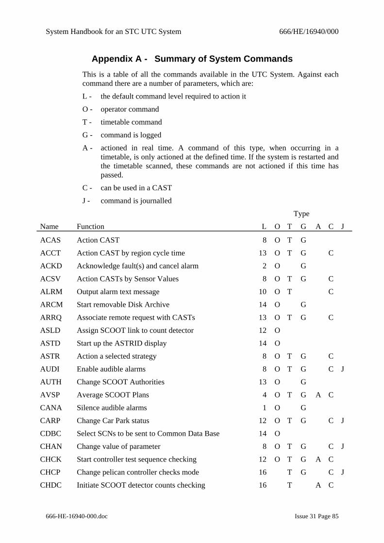
System Handbook for an STC UTC System 666/HE/16940/000
666-HE-16940-000.doc Issue 31 Page 85
Appendix A - Summary of System Commands This is a table of all the commands available in the UTC System. Against each command there are a number of parameters, which are:
L - the default command level required to action it
O - operator command
T - timetable command
G - command is logged
A - actioned in real time. A command of this type, when occurring in a timetable, is only actioned at the defined time. If the system is restarted and the timetable scanned, these commands are not actioned if this time has passed.
C - can be used in a CAST
J - command is journalled
Type
Name Function L O T G A C J
ACAS Action CAST 8 O T G
ACCT Action CAST by region cycle time 13 O T G C
ACKD Acknowledge fault(s) and cancel alarm 2 O G
ACSV Action CASTs by Sensor Values 8 O T G C
ALRM Output alarm text message 10 O T C
ARCM Start removable Disk Archive 14 O G
ARRQ Associate remote request with CASTs 13 O T G C
ASLD Assign SCOOT link to count detector 12 O
ASTD Start up the ASTRID display 14 O
ASTR Action a selected strategy 8 O T G C
AUDI Enable audible alarms 8 O T G C J
AUTH Change SCOOT Authorities 13 O G
AVSP Average SCOOT Plans 4 O T G A C
CANA Silence audible alarms 1 O G
CARP Change Car Park status 12 O T G C J
CDBC Select SCNs to be sent to Common Data Base 14 O
CHAN Change value of parameter 8 O T G C J
CHCK Start controller test sequence checking 12 O T G A C
CHCP Change pelican controller checks mode 16 T G C J
CHDC Initiate SCOOT detector counts checking 16 T A C
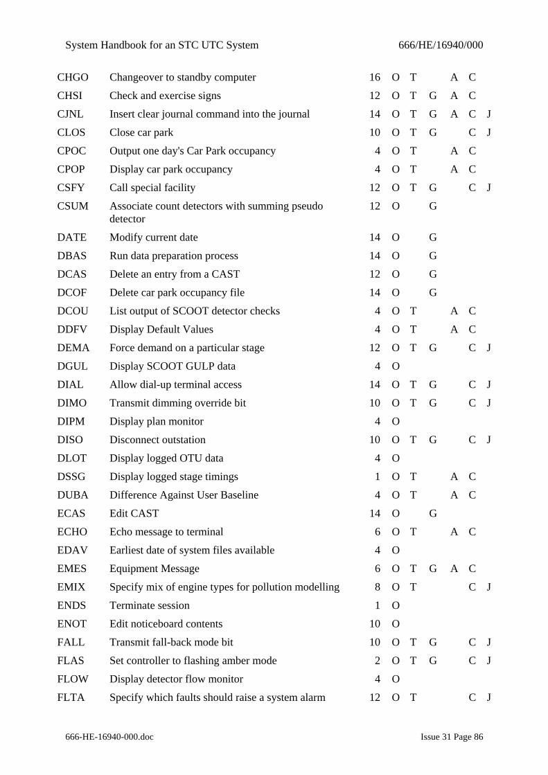
System Handbook for an STC UTC System 666/HE/16940/000
666-HE-16940-000.doc Issue 31 Page 86
CHGO Changeover to standby computer 16 O T A C
CHSI Check and exercise signs 12 O T G A C
CJNL Insert clear journal command into the journal 14 O T G A C J
CLOS Close car park 10 O T G C J
CPOC Output one day's Car Park occupancy 4 O T A C
CPOP Display car park occupancy 4 O T A C
CSFY Call special facility 12 O T G C J
CSUM Associate count detectors with summing pseudo detector
12 O G
DATE Modify current date 14 O G
DBAS Run data preparation process 14 O G
DCAS Delete an entry from a CAST 12 O G
DCOF Delete car park occupancy file 14 O G
DCOU List output of SCOOT detector checks 4 O T A C
DDFV Display Default Values 4 O T A C
DEMA Force demand on a particular stage 12 O T G C J
DGUL Display SCOOT GULP data 4 O
DIAL Allow dial-up terminal access 14 O T G C J
DIMO Transmit dimming override bit 10 O T G C J
DIPM Display plan monitor 4 O
DISO Disconnect outstation 10 O T G C J
DLOT Display logged OTU data 4 O
DSSG Display logged stage timings 1 O T A C
DUBA Difference Against User Baseline 4 O T A C
ECAS Edit CAST 14 O G
ECHO Echo message to terminal 6 O T A C
EDAV Earliest date of system files available 4 O
EMES Equipment Message 6 O T G A C
EMIX Specify mix of engine types for pollution modelling 8 O T C J
ENDS Terminate session 1 O
ENOT Edit noticeboard contents 10 O
FALL Transmit fall-back mode bit 10 O T G C J
FLAS Set controller to flashing amber mode 2 O T G C J
FLOW Display detector flow monitor 4 O
FLTA Specify which faults should raise a system alarm 12 O T C J
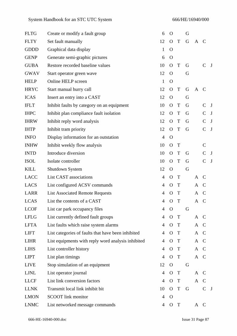
System Handbook for an STC UTC System 666/HE/16940/000
666-HE-16940-000.doc Issue 31 Page 87
FLTG Create or modify a fault group 6 O G
FLTY Set fault manually 12 O T G A C
GDDD Graphical data display 1 O
GENP Generate semi-graphic pictures 6 O
GUBA Restore recorded baseline values 10 O T G C J
GWAV Start operator green wave 12 O G
HELP Online HELP screen 1 O
HRYC Start manual hurry call 12 O T G A C
ICAS Insert an entry into a CAST 12 O G
IFLT Inhibit faults by category on an equipment 10 O T G C J
IHPC Inhibit plan compliance fault isolation 12 O T G C J
IHRW Inhibit reply word analysis 12 O T G C J
IHTP Inhibit tram priority 12 O T G C J
INFO Display information for an outstation 4 O
INHW Inhibit weekly flow analysis 10 O T C
INTD Introduce diversion 10 O T G C J
ISOL Isolate controller 10 O T G C J
KILL Shutdown System 12 O G
LACC List CAST associations 4 O T A C
LACS List configured ACSV commands 4 O T A C
LARR List Associated Remote Requests 4 O T A C
LCAS List the contents of a CAST 4 O T A C
LCOF List car park occupancy files 4 O G
LFLG List currently defined fault groups 4 O T A C
LFTA List faults which raise system alarms 4 O T A C
LIFT List categories of faults that have been inhibited 4 O T A C
LIHR List equipments with reply word analysis inhibited 4 O T A C
LIHS List controller history 4 O T A C
LIPT List plan timings 4 O T A C
LIVE Stop simulation of an equipment 12 O G
LJNL List operator journal 4 O T A C
LLCF List link conversion factors 4 O T A C
LLNK Transmit local link inhibit bit 10 O T G C J
LMON SCOOT link monitor 4 O
LNMC List networked message commands 4 O T A C
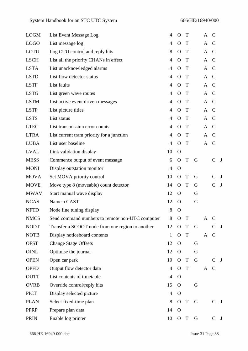
System Handbook for an STC UTC System 666/HE/16940/000
666-HE-16940-000.doc Issue 31 Page 88
LOGM List Event Message Log 4 O T A C
LOGO List message log 4 O T A C
LOTU Log OTU control and reply bits 8 O T A C
LSCH List all the priority CHANs in effect 4 O T A C
LSTA List unacknowledged alarms 4 O T A C
LSTD List flow detector status 4 O T A C
LSTF List faults 4 O T A C
LSTG List green wave routes 4 O T A C
LSTM List active event driven messages 4 O T A C
LSTP List picture titles 4 O T A C
LSTS List status 4 O T A C
LTEC List transmission error counts 4 O T A C
LTRA List current tram priority for a junction 4 O T A C
LUBA List user baseline 4 O T A C
LVAL Link validation display 10 O
MESS Commence output of event message 6 O T G C J
MONI Display outstation monitor 4 O
MOVA Set MOVA priority control 10 O T G C J
MOVE Move type 8 (moveable) count detector 14 O T G C J
MWAV Start manual wave display 12 O G
NCAS Name a CAST 12 O G
NFTD Node fine tuning display 8 O
NMCS Send command numbers to remote non-UTC computer 8 O T A C
NODT Transfer a SCOOT node from one region to another 12 O T G C J
NOTB Display noticeboard contents 1 O T A C
OFST Change Stage Offsets 12 O G
OJNL Optimise the journal 12 O G
OPEN Open car park 10 O T G C J
OPFD Output flow detector data 4 O T A C
OUTT List contents of timetable 4 O
OVRB Override control/reply bits 15 O G
PICT Display selected picture 4 O
PLAN Select fixed-time plan 8 O T G C J
PPRP Prepare plan data 14 O
PRIN Enable log printer 10 O T G C J
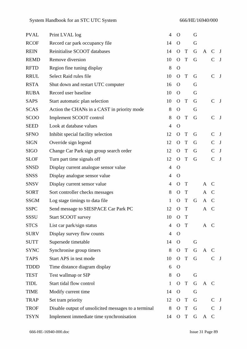
System Handbook for an STC UTC System 666/HE/16940/000
666-HE-16940-000.doc Issue 31 Page 89
PVAL Print LVAL log 4 O G
RCOF Record car park occupancy file 14 O G
REIN Reinitialise SCOOT databases 14 O T G A C J
REMD Remove diversion 10 O T G C J
RFTD Region fine tuning display 8 O
RRUL Select Raid rules file 10 O T G C J
RSTA Shut down and restart UTC computer 16 O G
RUBA Record user baseline 10 O G
SAPS Start automatic plan selection 10 O T G C J
SCAS Action the CHANs in a CAST in priority mode 8 O G
SCOO Implement SCOOT control 8 O T G C J
SEED Look at database values 4 O
SFNO Inhibit special facility selection 12 O T G C J
SIGN Override sign legend 12 O T G C J
SIGO Change Car Park sign group search order 12 O T G C J
SLOF Turn part time signals off 12 O T G C J
SNSD Display current analogue sensor value 4 O
SNSS Display analogue sensor value 4 O
SNSV Display current sensor value 4 O T A C
SORT Sort controller checks messages 8 O T A C
SSGM Log stage timings to data file 1 O T G A C
SSPC Send message to SIESPACE Car Park PC 12 O T A C
SSSU Start SCOOT survey 10 O T
STCS List car park/sign status 4 O T A C
SURV Display survey flow counts 4 O
SUTT Supersede timetable 14 O G
SYNC Synchronise group timers 8 O T G A C
TAPS Start APS in test mode 10 O T G C J
TDDD Time distance diagram display 6 O
TEST Test wallmap or SIP 8 O G
TIDL Start tidal flow control 1 O T G A C
TIME Modify current time 14 O G
TRAP Set tram priority 12 O T G C J
TROF Disable output of unsolicited messages to a terminal 8 O T G C J
TSYN Implement immediate time synchronisation 14 O T G A C
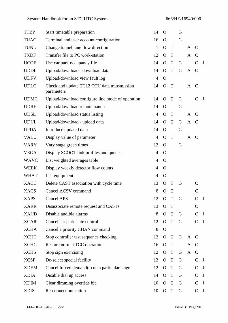
System Handbook for an STC UTC System 666/HE/16940/000
666-HE-16940-000.doc Issue 31 Page 90
TTBP Start timetable preparation 14 O G
TUAC Terminal and user account configuration 16 O G
TUNL Change tunnel lane flow direction 1 O T A C
TXDF Transfer file to PC work-station 12 O T A C
UCOF Use car park occupancy file 14 O T G C J
UDDL Upload/download - download data 14 O T G A C
UDFV Upload/download view fault log 4 O
UDLC Check and update TC12 OTU data transmission parameters
14 O T A C
UDMC Upload/download configure line mode of operation 14 O T G C J
UDRH Upload/download remote handset 14 O G
UDSL Upload/download status listing 4 O T A C
UDUL Upload/download - upload data 14 O T G A C
UPDA Introduce updated data 14 O G
VALU Display value of parameter 4 O T A C
VARY Vary stage green times 12 O G
VEGA Display SCOOT link profiles and queues 4 O
WAVC List weighted averages table 4 O
WEEK Display weekly detector flow counts 4 O
WHAT List equipment 4 O
XACC Delete CAST association with cycle time 13 O T G C
XACS Cancel ACSV command 8 O T C
XAPS Cancel APS 12 O T G C J
XARR Disassociate remote request and CASTs 13 O T C
XAUD Disable audible alarms 8 O T G C J
XCAR Cancel car park state control 12 O T G C J
XCHA Cancel a priority CHAN command 8 O
XCHC Stop controller test sequence checking 12 O T G A C
XCHG Restore normal TCC operation 16 O T A C
XCHS Stop sign exercising 12 O T G A C
XCSF De-select special facility 12 O T G C J
XDEM Cancel forced demand(s) on a particular stage 12 O T G C J
XDIA Disable dial up access 14 O T G C J
XDIM Clear dimming override bit 10 O T G C J
XDIS Re-connect outstation 10 O T G C J
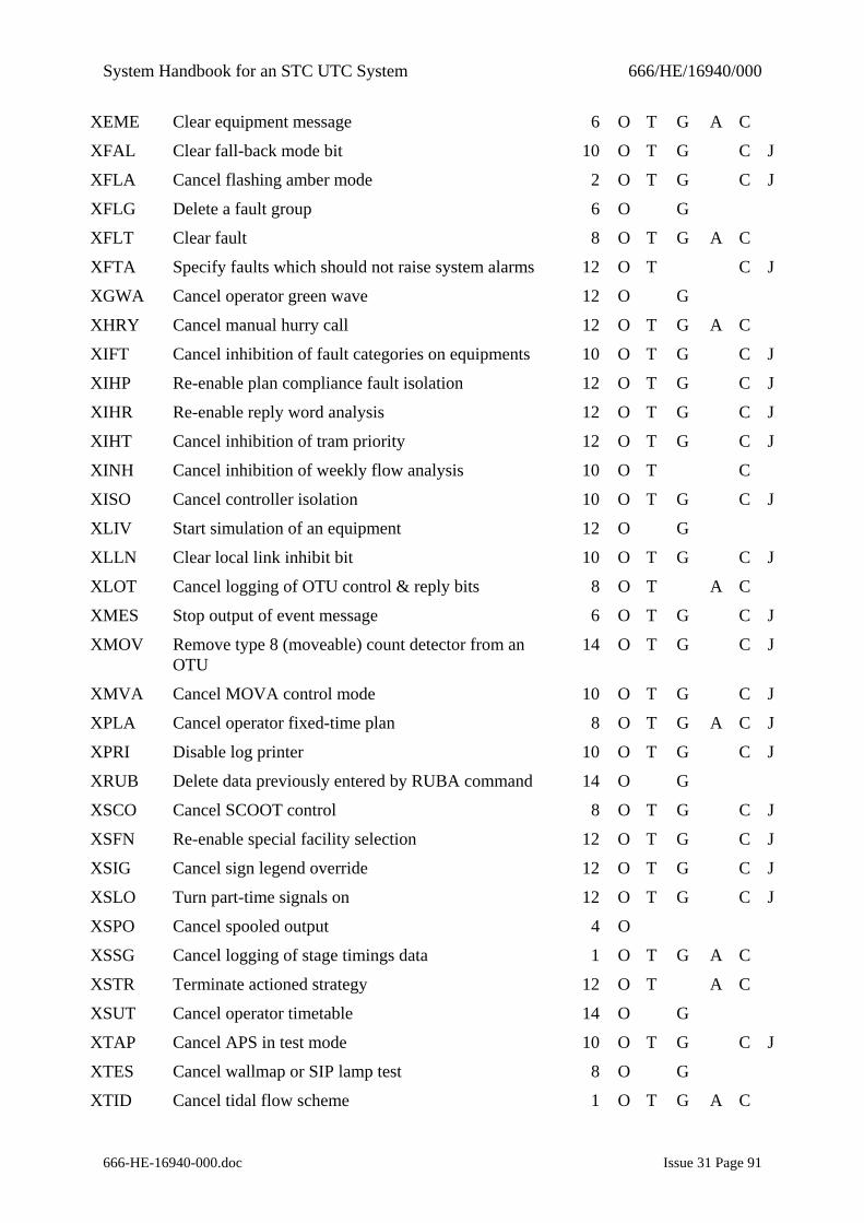
System Handbook for an STC UTC System 666/HE/16940/000
666-HE-16940-000.doc Issue 31 Page 91
XEME Clear equipment message 6 O T G A C
XFAL Clear fall-back mode bit 10 O T G C J
XFLA Cancel flashing amber mode 2 O T G C J
XFLG Delete a fault group 6 O G
XFLT Clear fault 8 O T G A C
XFTA Specify faults which should not raise system alarms 12 O T C J
XGWA Cancel operator green wave 12 O G
XHRY Cancel manual hurry call 12 O T G A C
XIFT Cancel inhibition of fault categories on equipments 10 O T G C J
XIHP Re-enable plan compliance fault isolation 12 O T G C J
XIHR Re-enable reply word analysis 12 O T G C J
XIHT Cancel inhibition of tram priority 12 O T G C J
XINH Cancel inhibition of weekly flow analysis 10 O T C
XISO Cancel controller isolation 10 O T G C J
XLIV Start simulation of an equipment 12 O G
XLLN Clear local link inhibit bit 10 O T G C J
XLOT Cancel logging of OTU control & reply bits 8 O T A C
XMES Stop output of event message 6 O T G C J
XMOV Remove type 8 (moveable) count detector from an OTU
14 O T G C J
XMVA Cancel MOVA control mode 10 O T G C J
XPLA Cancel operator fixed-time plan 8 O T G A C J
XPRI Disable log printer 10 O T G C J
XRUB Delete data previously entered by RUBA command 14 O G
XSCO Cancel SCOOT control 8 O T G C J
XSFN Re-enable special facility selection 12 O T G C J
XSIG Cancel sign legend override 12 O T G C J
XSLO Turn part-time signals on 12 O T G C J
XSPO Cancel spooled output 4 O
XSSG Cancel logging of stage timings data 1 O T G A C
XSTR Terminate actioned strategy 12 O T A C
XSUT Cancel operator timetable 14 O G
XTAP Cancel APS in test mode 10 O T G C J
XTES Cancel wallmap or SIP lamp test 8 O G
XTID Cancel tidal flow scheme 1 O T G A C
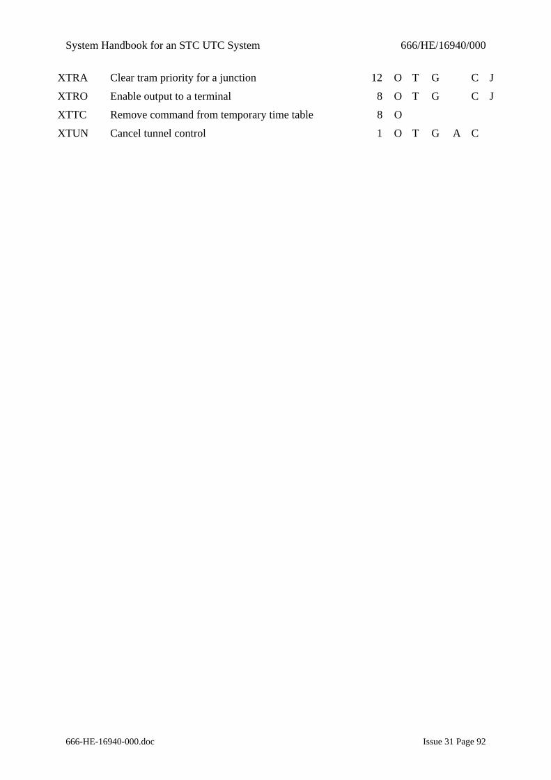
System Handbook for an STC UTC System 666/HE/16940/000
666-HE-16940-000.doc Issue 31 Page 92
XTRA Clear tram priority for a junction 12 O T G C J
XTRO Enable output to a terminal 8 O T G C J
XTTC Remove command from temporary time table 8 O
XTUN Cancel tunnel control 1 O T G A C
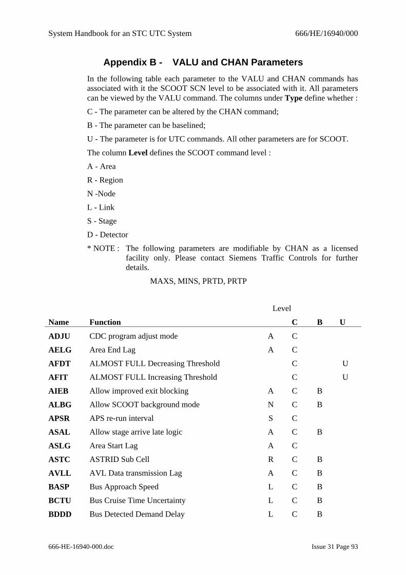
System Handbook for an STC UTC System 666/HE/16940/000
666-HE-16940-000.doc Issue 31 Page 93
Appendix B - VALU and CHAN Parameters In the following table each parameter to the VALU and CHAN commands has associated with it the SCOOT SCN level to be associated with it. All parameters can be viewed by the VALU command. The columns under Type define whether :
C - The parameter can be altered by the CHAN command;
B - The parameter can be baselined;
U - The parameter is for UTC commands. All other parameters are for SCOOT.
The column Level defines the SCOOT command level :
A - Area
R - Region
N -Node
L - Link
S - Stage
D - Detector
* NOTE : The following parameters are modifiable by CHAN as a licensed facility only. Please contact Siemens Traffic Controls for further details.
MAXS, MINS, PRTD, PRTP
Level
Name Function C B U
ADJU CDC program adjust mode A C
AELG Area End Lag A C
AFDT ALMOST FULL Decreasing Threshold C U
AFIT ALMOST FULL Increasing Threshold C U
AIEB Allow improved exit blocking A C B
ALBG Allow SCOOT background mode N C B
APSR APS re-run interval S C
ASAL Allow stage arrive late logic A C B
ASLG Area Start Lag A C
ASTC ASTRID Sub Cell R C B
AVLL AVL Data transmission Lag A C B
BASP Bus Approach Speed L C B
BCTU Bus Cruise Time Uncertainty L C B
BDDD Bus Detected Demand Delay L C B
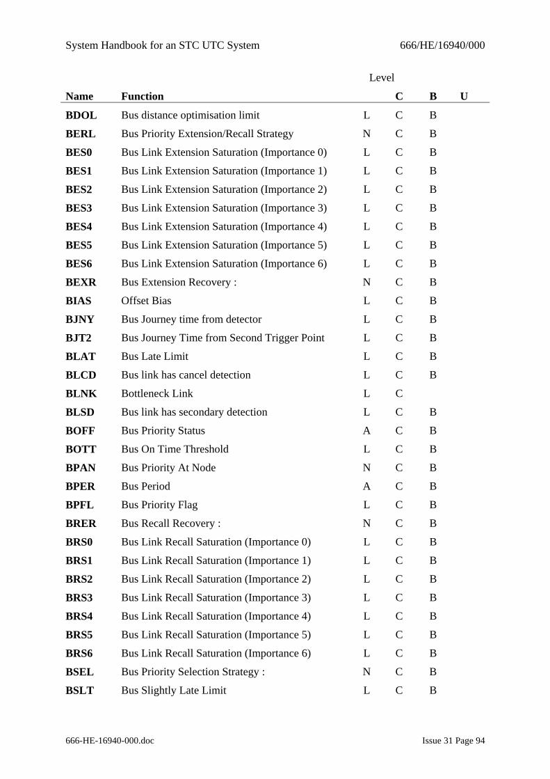
System Handbook for an STC UTC System 666/HE/16940/000
666-HE-16940-000.doc Issue 31 Page 94
Level
Name Function C B U
BDOL Bus distance optimisation limit L C B
BERL Bus Priority Extension/Recall Strategy N C B
BES0 Bus Link Extension Saturation (Importance 0) L C B
BES1 Bus Link Extension Saturation (Importance 1) L C B
BES2 Bus Link Extension Saturation (Importance 2) L C B
BES3 Bus Link Extension Saturation (Importance 3) L C B
BES4 Bus Link Extension Saturation (Importance 4) L C B
BES5 Bus Link Extension Saturation (Importance 5) L C B
BES6 Bus Link Extension Saturation (Importance 6) L C B
BEXR Bus Extension Recovery : N C B
BIAS Offset Bias L C B
BJNY Bus Journey time from detector L C B
BJT2 Bus Journey Time from Second Trigger Point L C B
BLAT Bus Late Limit L C B
BLCD Bus link has cancel detection L C B
BLNK Bottleneck Link L C
BLSD Bus link has secondary detection L C B
BOFF Bus Priority Status A C B
BOTT Bus On Time Threshold L C B
BPAN Bus Priority At Node N C B
BPER Bus Period A C B
BPFL Bus Priority Flag L C B
BRER Bus Recall Recovery : N C B
BRS0 Bus Link Recall Saturation (Importance 0) L C B
BRS1 Bus Link Recall Saturation (Importance 1) L C B
BRS2 Bus Link Recall Saturation (Importance 2) L C B
BRS3 Bus Link Recall Saturation (Importance 3) L C B
BRS4 Bus Link Recall Saturation (Importance 4) L C B
BRS5 Bus Link Recall Saturation (Importance 5) L C B
BRS6 Bus Link Recall Saturation (Importance 6) L C B
BSEL Bus Priority Selection Strategy : N C B
BSLT Bus Slightly Late Limit L C B
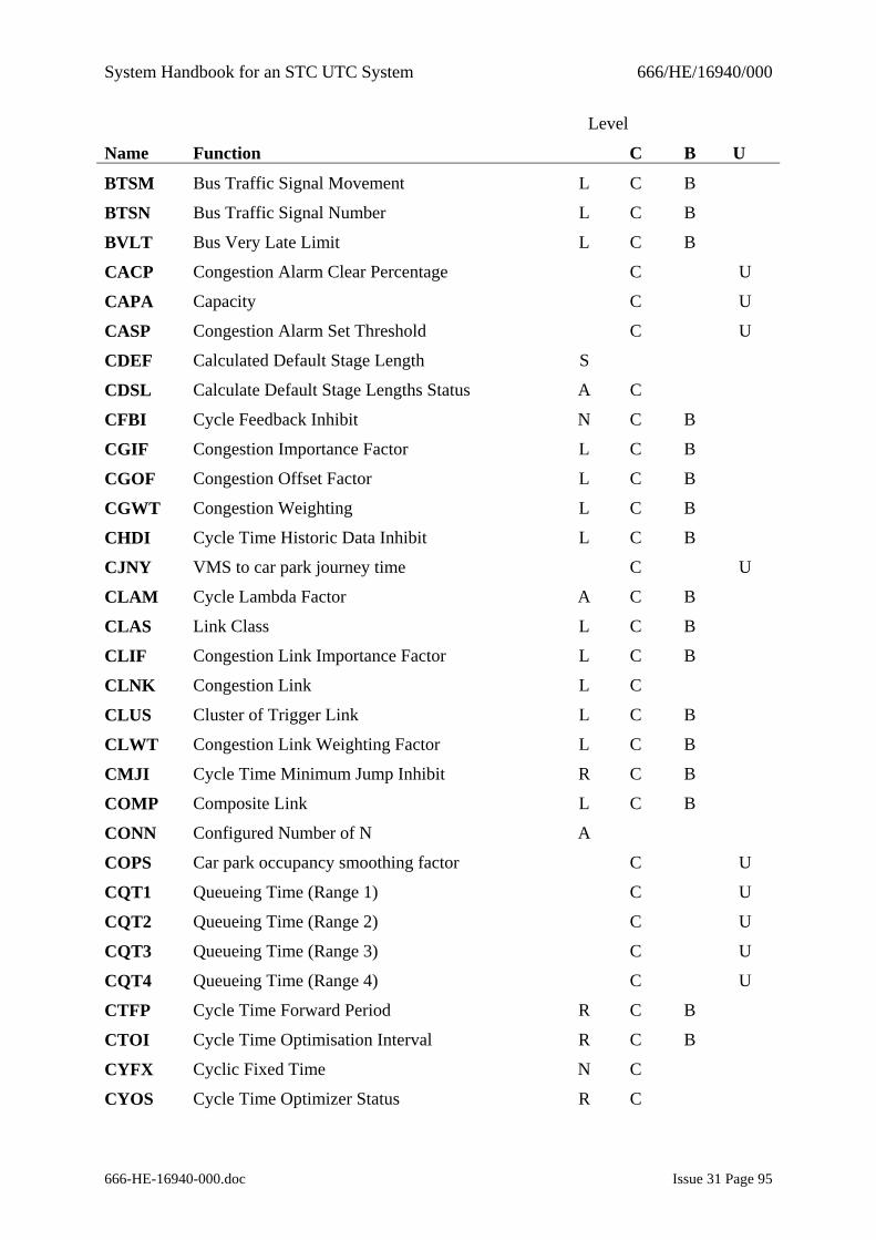
System Handbook for an STC UTC System 666/HE/16940/000
666-HE-16940-000.doc Issue 31 Page 95
Level
Name Function C B U
BTSM Bus Traffic Signal Movement L C B
BTSN Bus Traffic Signal Number L C B
BVLT Bus Very Late Limit L C B
CACP Congestion Alarm Clear Percentage C U
CAPA Capacity C U
CASP Congestion Alarm Set Threshold C U
CDEF Calculated Default Stage Length S
CDSL Calculate Default Stage Lengths Status A C
CFBI Cycle Feedback Inhibit N C B
CGIF Congestion Importance Factor L C B
CGOF Congestion Offset Factor L C B
CGWT Congestion Weighting L C B
CHDI Cycle Time Historic Data Inhibit L C B
CJNY VMS to car park journey time C U
CLAM Cycle Lambda Factor A C B
CLAS Link Class L C B
CLIF Congestion Link Importance Factor L C B
CLNK Congestion Link L C
CLUS Cluster of Trigger Link L C B
CLWT Congestion Link Weighting Factor L C B
CMJI Cycle Time Minimum Jump Inhibit R C B
COMP Composite Link L C B
CONN Configured Number of N A
COPS Car park occupancy smoothing factor C U
CQT1 Queueing Time (Range 1) C U
CQT2 Queueing Time (Range 2) C U
CQT3 Queueing Time (Range 3) C U
CQT4 Queueing Time (Range 4) C U
CTFP Cycle Time Forward Period R C B
CTOI Cycle Time Optimisation Interval R C B
CYFX Cyclic Fixed Time N C
CYOS Cycle Time Optimizer Status R C
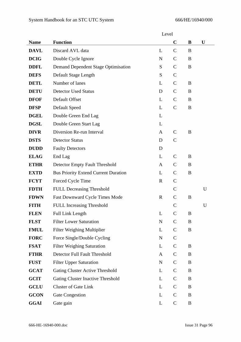
System Handbook for an STC UTC System 666/HE/16940/000
666-HE-16940-000.doc Issue 31 Page 96
Level
Name Function C B U
DAVL Discard AVL data L C B
DCIG Double Cycle Ignore N C B
DDFL Demand Dependent Stage Optimisation S C B
DEFS Default Stage Length S C
DETL Number of lanes L C B
DETU Detector Used Status D C B
DFOF Default Offset L C B
DFSP Default Speed L C B
DGEL Double Green End Lag L
DGSL Double Green Start Lag L
DIVR Diversion Re-run Interval A C B
DSTS Detector Status D C
DUDD Faulty Detectors D
ELAG End Lag L C B
ETHR Detector Empty Fault Threshold A C B
EXTD Bus Priority Extend Current Duration L C B
FCYT Forced Cycle Time R C
FDTH FULL Decreasing Threshold C U
FDWN Fast Downward Cycle Times Mode R C B
FITH FULL Increasing Threshold C U
FLEN Full Link Length L C B
FLST Filter Lower Saturation N C B
FMUL Filter Weighing Multiplier L C B
FORC Force Single/Double Cycling N C
FSAT Filter Weighing Saturation L C B
FTHR Detector Full Fault Threshold A C B
FUST Filter Upper Saturation N C B
GCAT Gating Cluster Active Threshold L C B
GCIT Gating Cluster Inactive Threshold L C B
GCLU Cluster of Gate Link L C B
GCON Gate Congestion L C B
GGAI Gate gain L C B
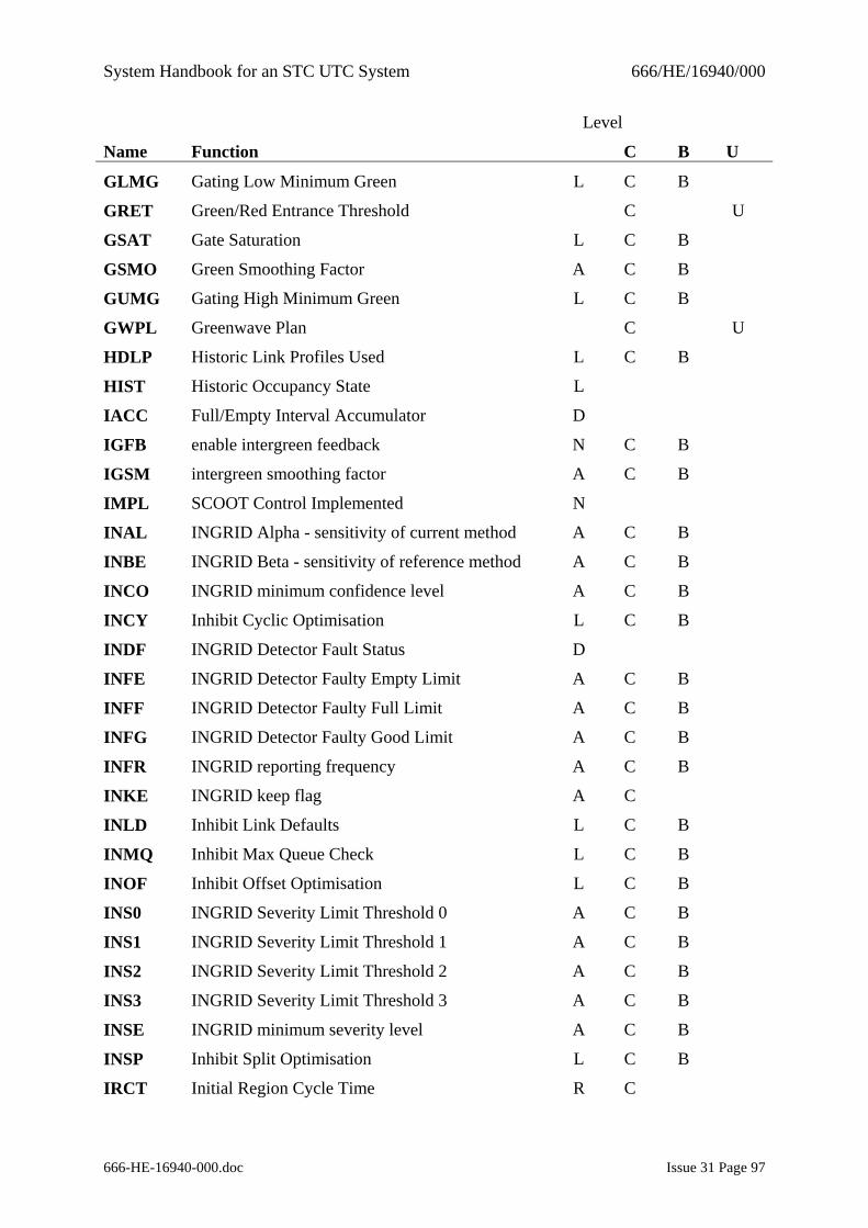
System Handbook for an STC UTC System 666/HE/16940/000
666-HE-16940-000.doc Issue 31 Page 97
Level
Name Function C B U
GLMG Gating Low Minimum Green L C B
GRET Green/Red Entrance Threshold C U
GSAT Gate Saturation L C B
GSMO Green Smoothing Factor A C B
GUMG Gating High Minimum Green L C B
GWPL Greenwave Plan C U
HDLP Historic Link Profiles Used L C B
HIST Historic Occupancy State L
IACC Full/Empty Interval Accumulator D
IGFB enable intergreen feedback N C B
IGSM intergreen smoothing factor A C B
IMPL SCOOT Control Implemented N
INAL INGRID Alpha - sensitivity of current method A C B
INBE INGRID Beta - sensitivity of reference method A C B
INCO INGRID minimum confidence level A C B
INCY Inhibit Cyclic Optimisation L C B
INDF INGRID Detector Fault Status D
INFE INGRID Detector Faulty Empty Limit A C B
INFF INGRID Detector Faulty Full Limit A C B
INFG INGRID Detector Faulty Good Limit A C B
INFR INGRID reporting frequency A C B
INKE INGRID keep flag A C
INLD Inhibit Link Defaults L C B
INMQ Inhibit Max Queue Check L C B
INOF Inhibit Offset Optimisation L C B
INS0 INGRID Severity Limit Threshold 0 A C B
INS1 INGRID Severity Limit Threshold 1 A C B
INS2 INGRID Severity Limit Threshold 2 A C B
INS3 INGRID Severity Limit Threshold 3 A C B
INSE INGRID minimum severity level A C B
INSP Inhibit Split Optimisation L C B
IRCT Initial Region Cycle Time R C
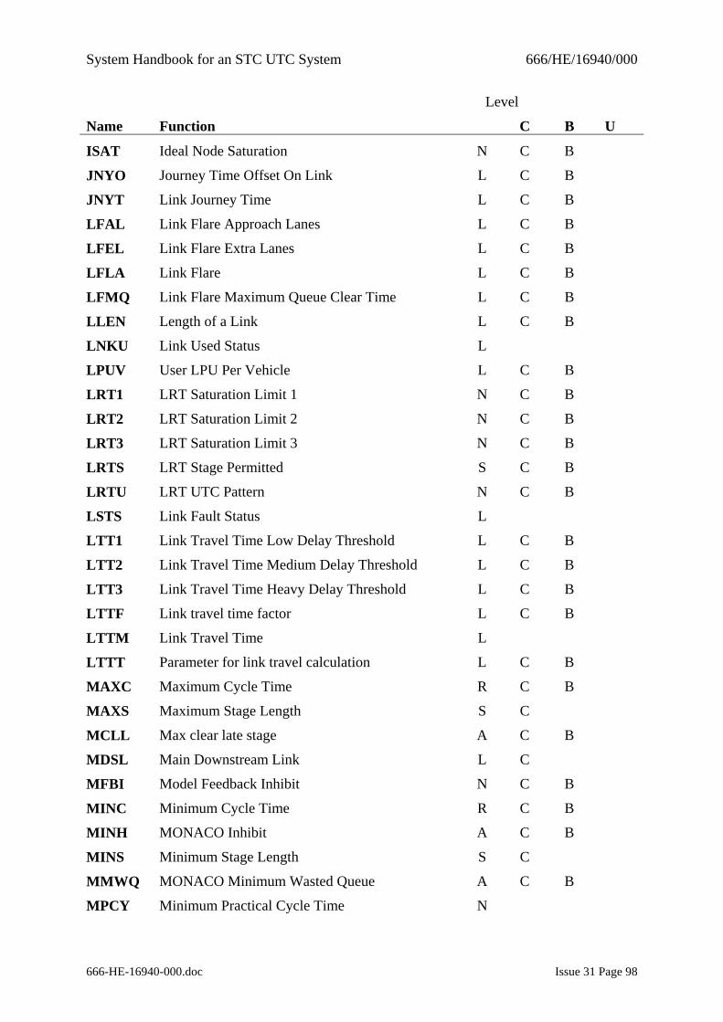
System Handbook for an STC UTC System 666/HE/16940/000
666-HE-16940-000.doc Issue 31 Page 98
Level
Name Function C B U
ISAT Ideal Node Saturation N C B
JNYO Journey Time Offset On Link L C B
JNYT Link Journey Time L C B
LFAL Link Flare Approach Lanes L C B
LFEL Link Flare Extra Lanes L C B
LFLA Link Flare L C B
LFMQ Link Flare Maximum Queue Clear Time L C B
LLEN Length of a Link L C B
LNKU Link Used Status L
LPUV User LPU Per Vehicle L C B
LRT1 LRT Saturation Limit 1 N C B
LRT2 LRT Saturation Limit 2 N C B
LRT3 LRT Saturation Limit 3 N C B
LRTS LRT Stage Permitted S C B
LRTU LRT UTC Pattern N C B
LSTS Link Fault Status L
LTT1 Link Travel Time Low Delay Threshold L C B
LTT2 Link Travel Time Medium Delay Threshold L C B
LTT3 Link Travel Time Heavy Delay Threshold L C B
LTTF Link travel time factor L C B
LTTM Link Travel Time L
LTTT Parameter for link travel calculation L C B
MAXC Maximum Cycle Time R C B
MAXS Maximum Stage Length S C
MCLL Max clear late stage A C B
MDSL Main Downstream Link L C
MFBI Model Feedback Inhibit N C B
MINC Minimum Cycle Time R C B
MINH MONACO Inhibit A C B
MINS Minimum Stage Length S C
MMWQ MONACO Minimum Wasted Queue A C B
MPCY Minimum Practical Cycle Time N
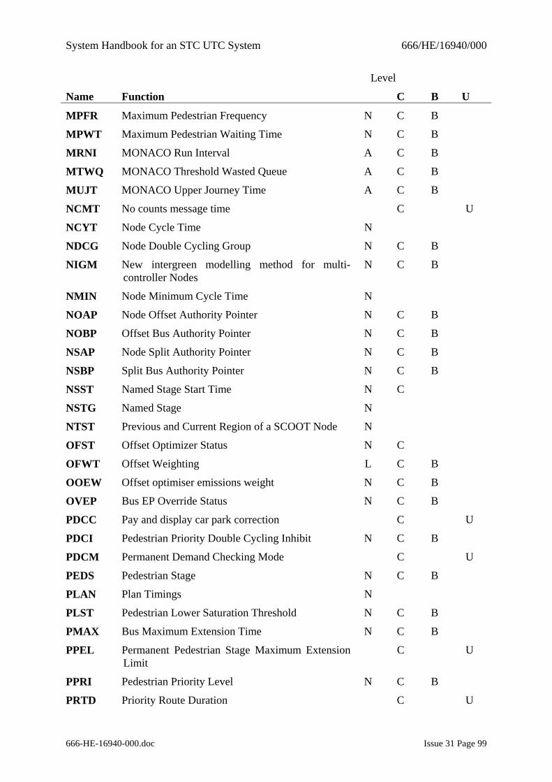
System Handbook for an STC UTC System 666/HE/16940/000
666-HE-16940-000.doc Issue 31 Page 99
Level
Name Function C B U
MPFR Maximum Pedestrian Frequency N C B
MPWT Maximum Pedestrian Waiting Time N C B
MRNI MONACO Run Interval A C B
MTWQ MONACO Threshold Wasted Queue A C B
MUJT MONACO Upper Journey Time A C B
NCMT No counts message time C U
NCYT Node Cycle Time N
NDCG Node Double Cycling Group N C B
NIGM New intergreen modelling method for multi-controller Nodes
N C B
NMIN Node Minimum Cycle Time N
NOAP Node Offset Authority Pointer N C B
NOBP Offset Bus Authority Pointer N C B
NSAP Node Split Authority Pointer N C B
NSBP Split Bus Authority Pointer N C B
NSST Named Stage Start Time N C
NSTG Named Stage N
NTST Previous and Current Region of a SCOOT Node N
OFST Offset Optimizer Status N C
OFWT Offset Weighting L C B
OOEW Offset optimiser emissions weight N C B
OVEP Bus EP Override Status N C B
PDCC Pay and display car park correction C U
PDCI Pedestrian Priority Double Cycling Inhibit N C B
PDCM Permanent Demand Checking Mode C U
PEDS Pedestrian Stage N C B
PLAN Plan Timings N
PLST Pedestrian Lower Saturation Threshold N C B
PMAX Bus Maximum Extension Time N C B
PPEL Permanent Pedestrian Stage Maximum Extension Limit
C U
PPRI Pedestrian Priority Level N C B
PRTD Priority Route Duration C U
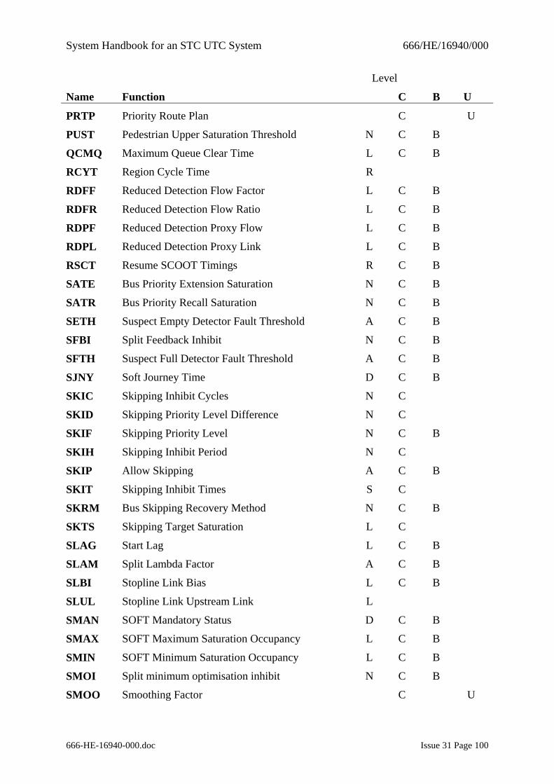
System Handbook for an STC UTC System 666/HE/16940/000
666-HE-16940-000.doc Issue 31 Page 100
Level
Name Function C B U
PRTP Priority Route Plan C U
PUST Pedestrian Upper Saturation Threshold N C B
QCMQ Maximum Queue Clear Time L C B
RCYT Region Cycle Time R
RDFF Reduced Detection Flow Factor L C B
RDFR Reduced Detection Flow Ratio L C B
RDPF Reduced Detection Proxy Flow L C B
RDPL Reduced Detection Proxy Link L C B
RSCT Resume SCOOT Timings R C B
SATE Bus Priority Extension Saturation N C B
SATR Bus Priority Recall Saturation N C B
SETH Suspect Empty Detector Fault Threshold A C B
SFBI Split Feedback Inhibit N C B
SFTH Suspect Full Detector Fault Threshold A C B
SJNY Soft Journey Time D C B
SKIC Skipping Inhibit Cycles N C
SKID Skipping Priority Level Difference N C
SKIF Skipping Priority Level N C B
SKIH Skipping Inhibit Period N C
SKIP Allow Skipping A C B
SKIT Skipping Inhibit Times S C
SKRM Bus Skipping Recovery Method N C B
SKTS Skipping Target Saturation L C
SLAG Start Lag L C B
SLAM Split Lambda Factor A C B
SLBI Stopline Link Bias L C B
SLUL Stopline Link Upstream Link L
SMAN SOFT Mandatory Status D C B
SMAX SOFT Maximum Saturation Occupancy L C B
SMIN SOFT Minimum Saturation Occupancy L C B
SMOI Split minimum optimisation inhibit N C B
SMOO Smoothing Factor C U
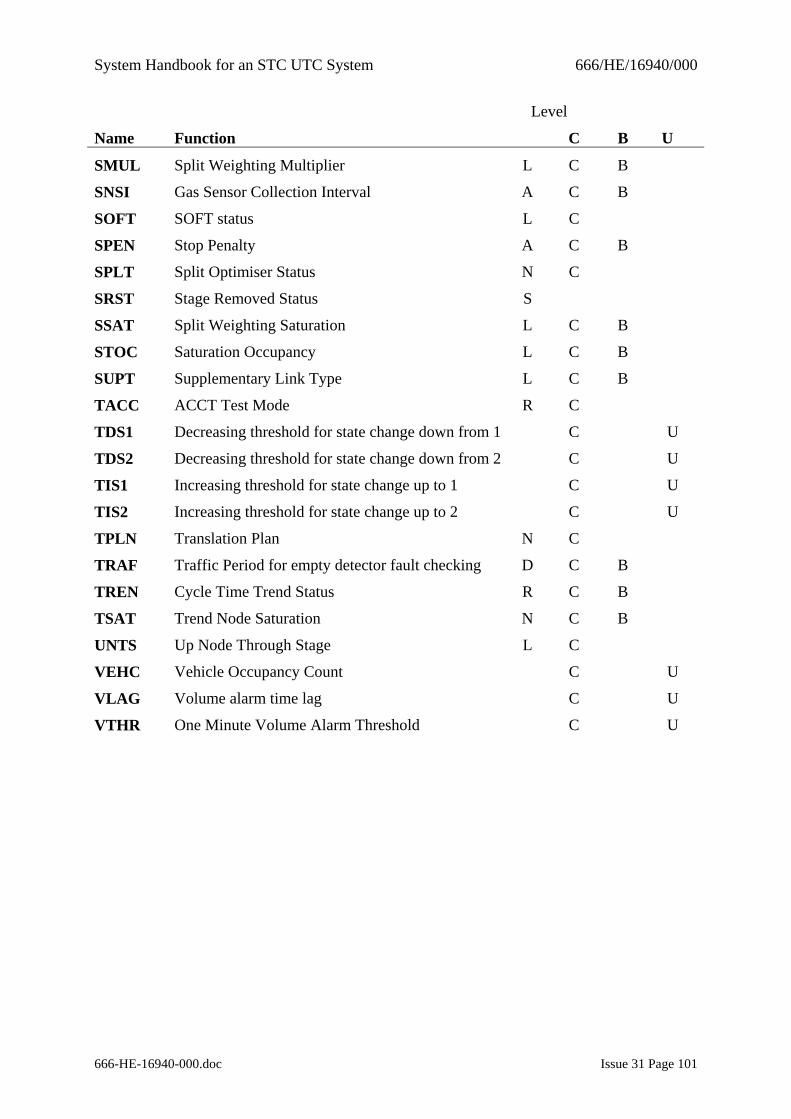
System Handbook for an STC UTC System 666/HE/16940/000
666-HE-16940-000.doc Issue 31 Page 101
Level
Name Function C B U
SMUL Split Weighting Multiplier L C B
SNSI Gas Sensor Collection Interval A C B
SOFT SOFT status L C
SPEN Stop Penalty A C B
SPLT Split Optimiser Status N C
SRST Stage Removed Status S
SSAT Split Weighting Saturation L C B
STOC Saturation Occupancy L C B
SUPT Supplementary Link Type L C B
TACC ACCT Test Mode R C
TDS1 Decreasing threshold for state change down from 1 C U
TDS2 Decreasing threshold for state change down from 2 C U
TIS1 Increasing threshold for state change up to 1 C U
TIS2 Increasing threshold for state change up to 2 C U
TPLN Translation Plan N C
TRAF Traffic Period for empty detector fault checking D C B
TREN Cycle Time Trend Status R C B
TSAT Trend Node Saturation N C B
UNTS Up Node Through Stage L C
VEHC Vehicle Occupancy Count C U
VLAG Volume alarm time lag C U
VTHR One Minute Volume Alarm Threshold C U
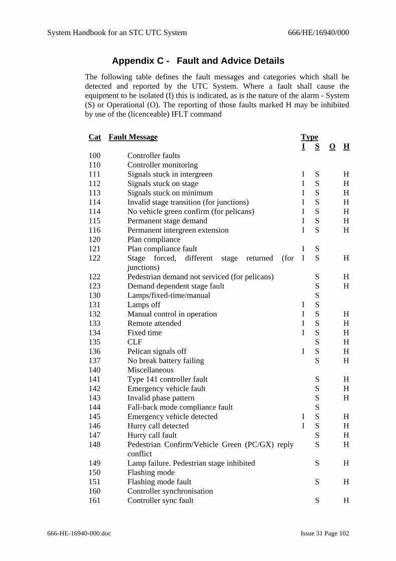
System Handbook for an STC UTC System 666/HE/16940/000
666-HE-16940-000.doc Issue 31 Page 102
Appendix C - Fault and Advice Details The following table defines the fault messages and categories which shall be detected and reported by the UTC System. Where a fault shall cause the equipment to be isolated (I) this is indicated, as is the nature of the alarm - System (S) or Operational (O). The reporting of those faults marked H may be inhibited by use of the (licenceable) IFLT command
Cat Fault Message Type I S O H 100 Controller faults 110 Controller monitoring 111 Signals stuck in intergreen I S H 112 Signals stuck on stage I S H 113 Signals stuck on minimum I S H 114 Invalid stage transition (for junctions) I S H 114 No vehicle green confirm (for pelicans) I S H 115 Permanent stage demand I S H 116 Permanent intergreen extension I S H 120 Plan compliance 121 Plan compliance fault I S 122 Stage forced, different stage returned (for
junctions) I S H
122 Pedestrian demand not serviced (for pelicans) S H 123 Demand dependent stage fault S H 130 Lamps/fixed-time/manual S 131 Lamps off I S 132 Manual control in operation I S H 133 Remote attended I S H 134 Fixed time I S H 135 CLF S H 136 Pelican signals off I S H 137 No break battery failing S H 140 Miscellaneous 141 Type 141 controller fault S H 142 Emergency vehicle fault S H 143 Invalid phase pattern S H 144 Fall-back mode compliance fault S 145 Emergency vehicle detected I S H 146 Hurry call detected I S H 147 Hurry call fault S H 148 Pedestrian Confirm/Vehicle Green (PC/GX) reply
conflict S H
149 Lamp failure. Pedestrian stage inhibited S H 150 Flashing mode 151 Flashing mode fault S H 160 Controller synchronisation 161 Controller sync fault S H
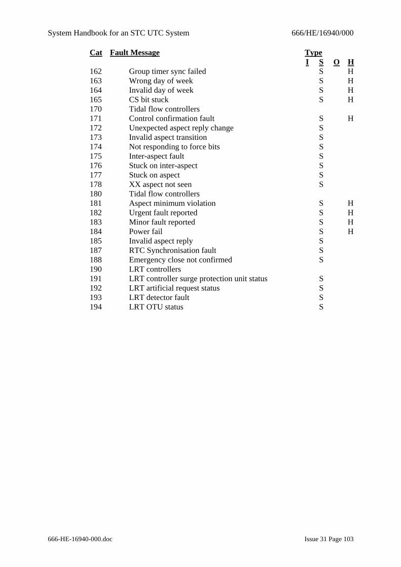
System Handbook for an STC UTC System 666/HE/16940/000
666-HE-16940-000.doc Issue 31 Page 103
Cat Fault Message Type I S O H 162 Group timer sync failed S H 163 Wrong day of week S H 164 Invalid day of week S H 165 CS bit stuck S H 170 Tidal flow controllers 171 Control confirmation fault S H 172 Unexpected aspect reply change S 173 Invalid aspect transition S 174 Not responding to force bits S 175 Inter-aspect fault S 176 Stuck on inter-aspect S 177 Stuck on aspect S 178 XX aspect not seen S 180 Tidal flow controllers 181 Aspect minimum violation S H 182 Urgent fault reported S H 183 Minor fault reported S H 184 Power fail S H 185 Invalid aspect reply S 187 RTC Synchronisation fault S 188 Emergency close not confirmed S 190 LRT controllers 191 LRT controller surge protection unit status S 192 LRT artificial request status S 193 LRT detector fault S 194 LRT OTU status S
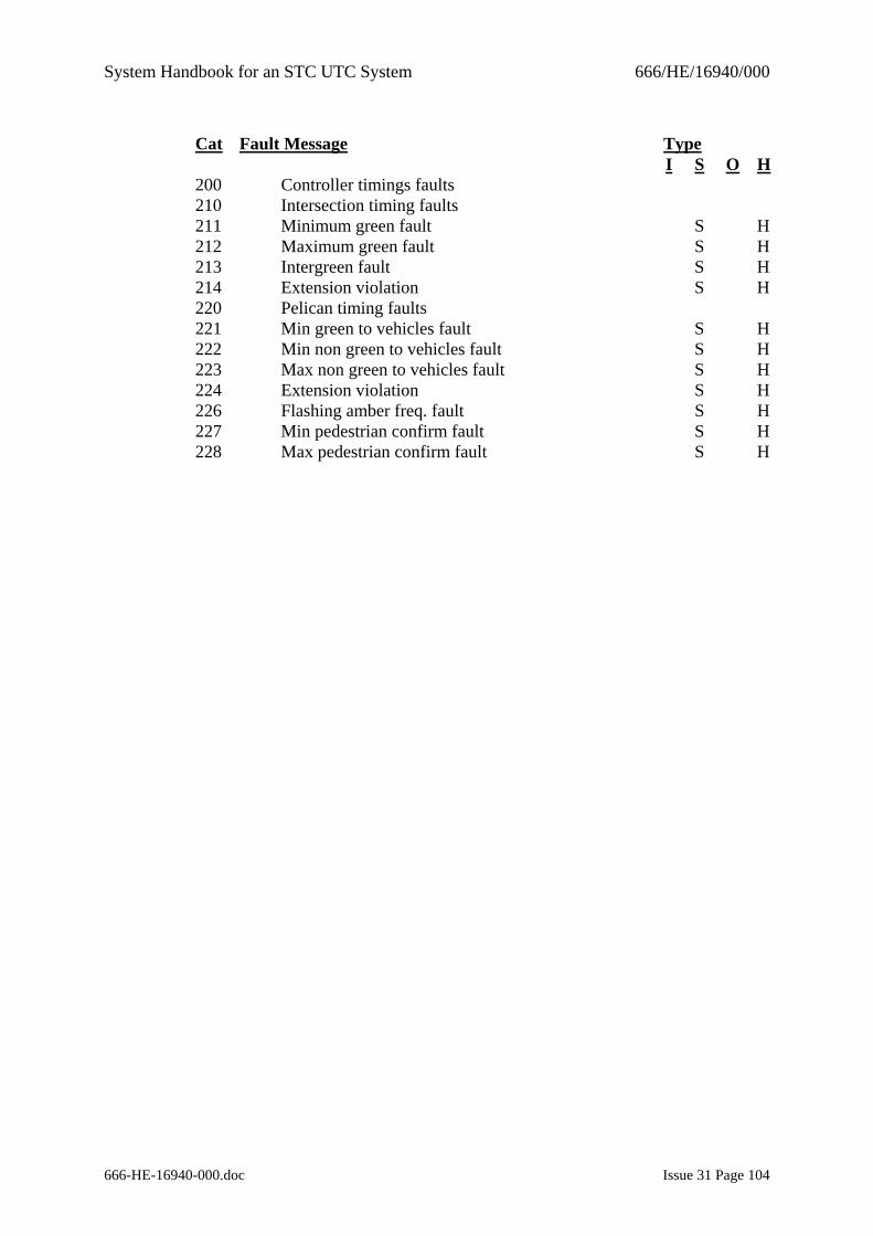
System Handbook for an STC UTC System 666/HE/16940/000
666-HE-16940-000.doc Issue 31 Page 104
Cat Fault Message Type I S O H 200 Controller timings faults 210 Intersection timing faults 211 Minimum green fault S H 212 Maximum green fault S H 213 Intergreen fault S H 214 Extension violation S H 220 Pelican timing faults 221 Min green to vehicles fault S H 222 Min non green to vehicles fault S H 223 Max non green to vehicles fault S H 224 Extension violation S H 226 Flashing amber freq. fault S H 227 Min pedestrian confirm fault S H 228 Max pedestrian confirm fault S H
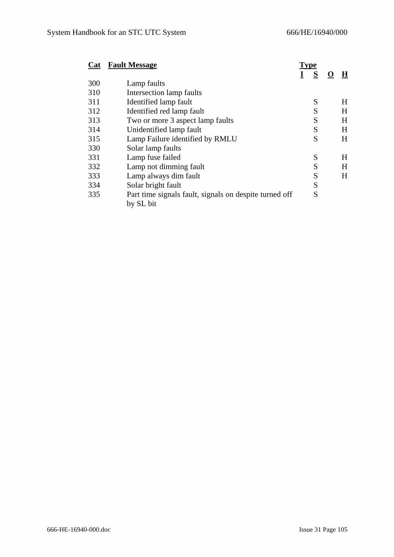
System Handbook for an STC UTC System 666/HE/16940/000
666-HE-16940-000.doc Issue 31 Page 105
Cat Fault Message Type I S O H 300 Lamp faults 310 Intersection lamp faults 311 Identified lamp fault S H 312 Identified red lamp fault S H 313 Two or more 3 aspect lamp faults S H 314 Unidentified lamp fault S H 315 Lamp Failure identified by RMLU S H 330 Solar lamp faults 331 Lamp fuse failed S H 332 Lamp not dimming fault S H 333 Lamp always dim fault S H 334 Solar bright fault S 335 Part time signals fault, signals on despite turned off
by SL bit S
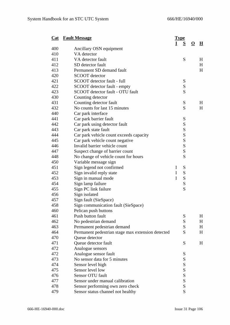
System Handbook for an STC UTC System 666/HE/16940/000
666-HE-16940-000.doc Issue 31 Page 106
Cat Fault Message Type I S O H 400 Ancillary OSN equipment 410 VA detector 411 VA detector fault S H 412 SD detector fault H 413 Permanent SD demand fault H 420 SCOOT detector 421 SCOOT detector fault - full S 422 SCOOT detector fault - empty S 423 SCOOT detector fault - OTU fault S 430 Counting detector 431 Counting detector fault S H 432 No counts for last 15 minutes S H 440 Car park interface 441 Car park barrier fault S 442 Car park using detector fault S 443 Car park state fault S 444 Car park vehicle count exceeds capacity S 445 Car park vehicle count negative S 446 Invalid barrier vehicle count S 447 Suspect change of barrier count S 448 No change of vehicle count for hours S 450 Variable message sign 451 Sign legend not confirmed I S 452 Sign invalid reply state I S 453 Sign in manual mode I S 454 Sign lamp failure S 455 Sign PC link failure S 456 Sign isolated 457 Sign fault (SieSpace) 458 Sign communication fault (SieSpace) 460 Pelican push buttons 461 Push button fault S H 462 No pedestrian demand S H 463 Permanent pedestrian demand S H 464 Permanent pedestrian stage max extension detected S H 470 Queue detector 471 Queue detector fault S H 472 Analogue sensors 472 Analogue sensor fault S 473 No sensor data for 5 minutes S 474 Sensor level high S 475 Sensor level low S 476 Sensor OTU fault S 477 Sensor under manual calibration S 478 Sensor performing own zero check S 479 Sensor status channel not healthy S
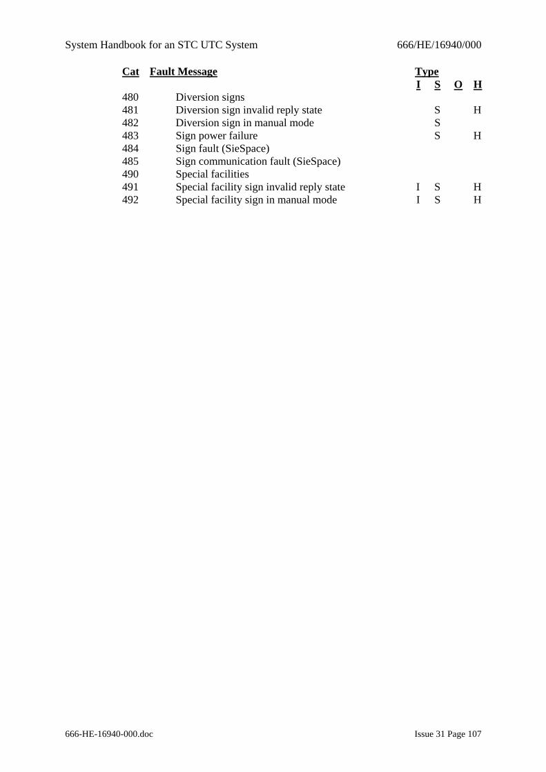
System Handbook for an STC UTC System 666/HE/16940/000
666-HE-16940-000.doc Issue 31 Page 107
Cat Fault Message Type I S O H 480 Diversion signs 481 Diversion sign invalid reply state S H 482 Diversion sign in manual mode S 483 Sign power failure S H 484 Sign fault (SieSpace) 485 Sign communication fault (SieSpace) 490 Special facilities 491 Special facility sign invalid reply state I S H 492 Special facility sign in manual mode I S H
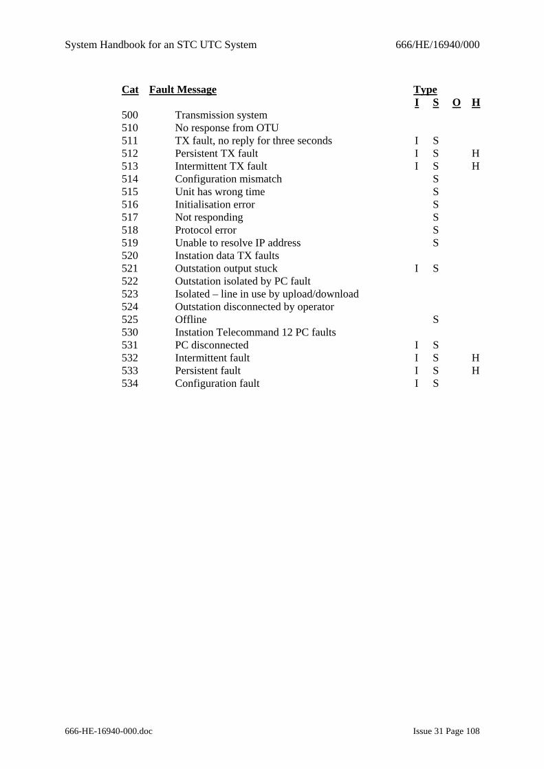
System Handbook for an STC UTC System 666/HE/16940/000
666-HE-16940-000.doc Issue 31 Page 108
Cat Fault Message Type I S O H 500 Transmission system 510 No response from OTU 511 TX fault, no reply for three seconds I S 512 Persistent TX fault I S H 513 Intermittent TX fault I S H 514 Configuration mismatch S 515 Unit has wrong time S 516 Initialisation error S 517 Not responding S 518 Protocol error S 519 Unable to resolve IP address S 520 Instation data TX faults 521 Outstation output stuck I S 522 Outstation isolated by PC fault 523 Isolated – line in use by upload/download 524 Outstation disconnected by operator 525 Offline S 530 Instation Telecommand 12 PC faults 531 PC disconnected I S 532 Intermittent fault I S H 533 Persistent fault I S H 534 Configuration fault I S
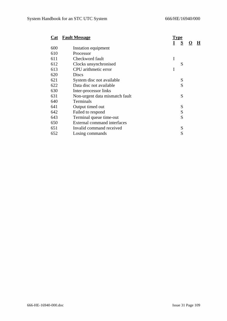
System Handbook for an STC UTC System 666/HE/16940/000
666-HE-16940-000.doc Issue 31 Page 109
Cat Fault Message Type I S O H 600 Instation equipment 610 Processor 611 Checkword fault I 612 Clocks unsynchronised S 613 CPU arithmetic error I 620 Discs 621 System disc not available S 622 Data disc not available S 630 Inter-processor links 631 Non-urgent data mismatch fault S 640 Terminals 641 Output timed out S 642 Failed to respond S 643 Terminal queue time-out S 650 External command interfaces 651 Invalid command received S 652 Losing commands S
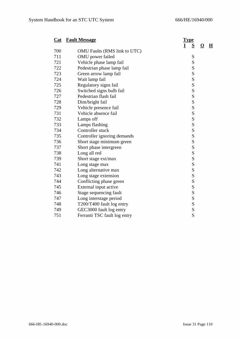
System Handbook for an STC UTC System 666/HE/16940/000
666-HE-16940-000.doc Issue 31 Page 110
Cat Fault Message Type I S O H 700 OMU Faults (RMS link to UTC) 711 OMU power failed S 721 Vehicle phase lamp fail S 722 Pedestrian phase lamp fail S 723 Green arrow lamp fail S 724 Wait lamp fail S 725 Regulatory signs fail S 726 Switched signs bulb fail S 727 Pedestrian flash fail S 728 Dim/bright fail S 729 Vehicle presence fail S 731 Vehicle absence fail S 732 Lamps off S 733 Lamps flashing S 734 Controller stuck S 735 Controller ignoring demands S 736 Short stage minimum green S 737 Short phase intergreen S 738 Long all red S 739 Short stage ext/max S 741 Long stage max S 742 Long alternative max S 743 Long stage extension S 744 Conflicting phase green S 745 External input active S 746 Stage sequencing fault S 747 Long interstage period S 748 T200/T400 fault log entry S 749 GEC3000 fault log entry S 751 Ferranti TSC fault log entry S
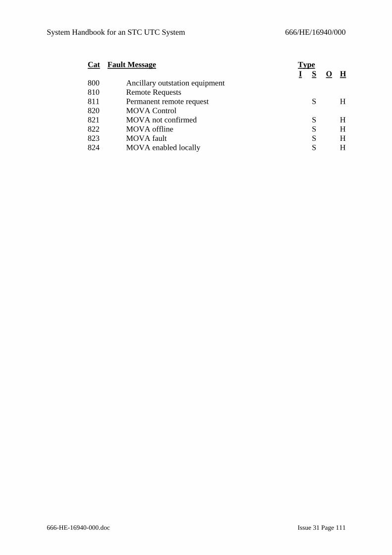
System Handbook for an STC UTC System 666/HE/16940/000
666-HE-16940-000.doc Issue 31 Page 111
Cat Fault Message Type I S O H 800 Ancillary outstation equipment 810 Remote Requests 811 Permanent remote request S H 820 MOVA Control 821 MOVA not confirmed S H 822 MOVA offline S H 823 MOVA fault S H 824 MOVA enabled locally S H
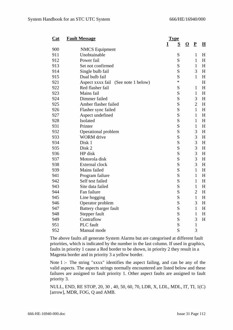
System Handbook for an STC UTC System 666/HE/16940/000
666-HE-16940-000.doc Issue 31 Page 112
Cat Fault Message Type I S O P H 900 NMCS Equipment 911 Unobtainable S 1 H 912 Power fail S 1 H 913 Set not confirmed S 1 H 914 Single bulb fail S 3 H 915 Dual bulb fail S 1 H 921 Aspect xxxx fail (See note 1 below) * H 922 Red flasher fail S 1 H 923 Mains fail S 1 H 924 Dimmer failed S 3 H 925 Amber flasher failed S 2 H 926 Flasher sync failed S 1 H 927 Aspect undefined S 1 H 928 Isolated S 1 H 931 Printer S 1 H 932 Operational problem S 3 H 933 WORM drive S 3 H 934 Disk 1 S 3 H 935 Disk 2 S 3 H 936 HP disk S 3 H 937 Motorola disk S 3 H 938 External clock S 3 H 939 Mains failed S 1 H 941 Program failure S 1 H 942 Self test failed S 1 H 943 Site data failed S 1 H 944 Fan failure S 2 H 945 Line hogging S 1 H 946 Operator problem S 3 H 947 Battery charger fault S 1 H 948 Stepper fault S 1 H 949 Contraflow S 3 H 951 PLC fault S 1 952 Manual mode S 3
The above faults all generate System Alarms but are categorised at different fault priorities, which is indicated by the number in the last column. If used in graphics, faults in priority 1 cause a Red border to be shown, in priority 2 they result in a Magenta border and in priority 3 a yellow border.
Note 1 :- The string "xxxx" identifies the aspect failing, and can be any of the valid aspects. The aspects strings normally encountered are listed below and these failures are assigned to fault priority 1. Other aspect faults are assigned to fault priority 3.
NULL, END, RE STOP, 20, 30 , 40, 50, 60, 70, LDR, X, LDL, MDL, IT, TI, 1(C) [arrow], MDR, FOG, Q and AMB.
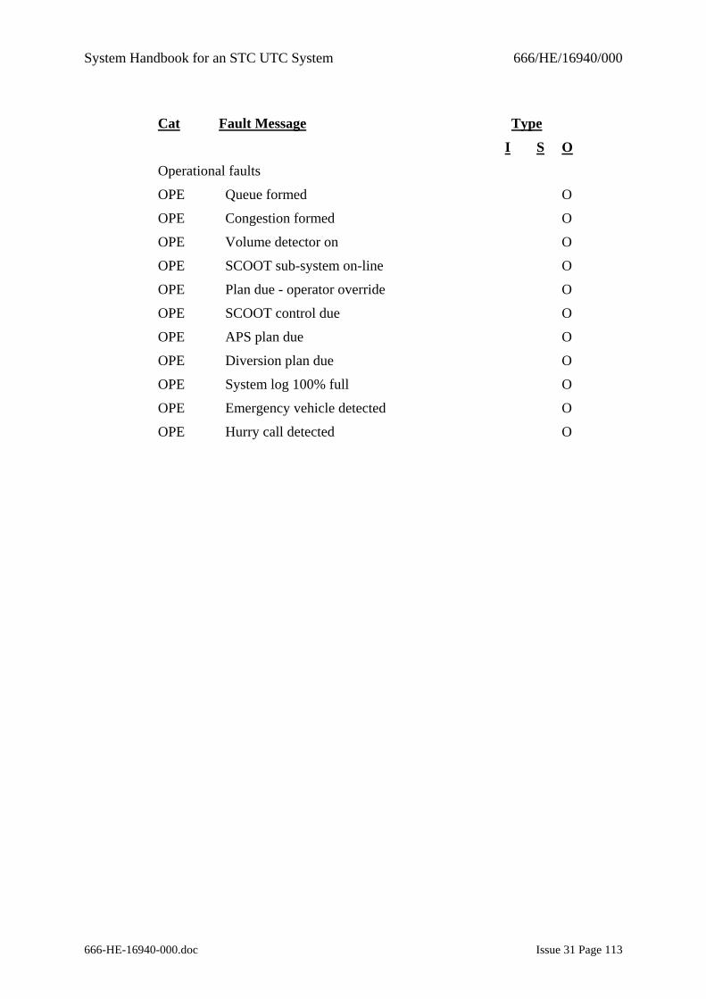
System Handbook for an STC UTC System 666/HE/16940/000
666-HE-16940-000.doc Issue 31 Page 113
Cat Fault Message Type
I S O
Operational faults
OPE Queue formed O
OPE Congestion formed O
OPE Volume detector on O
OPE SCOOT sub-system on-line O
OPE Plan due - operator override O
OPE SCOOT control due O
OPE APS plan due O
OPE Diversion plan due O
OPE System log 100% full O
OPE Emergency vehicle detected O
OPE Hurry call detected O
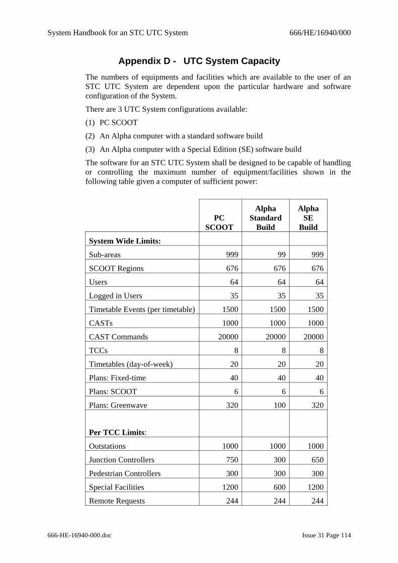
System Handbook for an STC UTC System 666/HE/16940/000
666-HE-16940-000.doc Issue 31 Page 114
Appendix D - UTC System Capacity The numbers of equipments and facilities which are available to the user of an STC UTC System are dependent upon the particular hardware and software configuration of the System.
There are 3 UTC System configurations available:
(1) PC SCOOT
(2) An Alpha computer with a standard software build
(3) An Alpha computer with a Special Edition (SE) software build
The software for an STC UTC System shall be designed to be capable of handling or controlling the maximum number of equipment/facilities shown in the following table given a computer of sufficient power:
PC
SCOOT
Alpha Standard
Build
Alpha SE
Build
System Wide Limits:
Sub-areas 999 99 999
SCOOT Regions 676 676 676
Users 64 64 64
Logged in Users 35 35 35
Timetable Events (per timetable) 1500 1500 1500
CASTs 1000 1000 1000
CAST Commands 20000 20000 20000
TCCs 8 8 8
Timetables (day-of-week) 20 20 20
Plans: Fixed-time 40 40 40
Plans: SCOOT 6 6 6
Plans: Greenwave 320 100 320
Per TCC Limits:
Outstations 1000 1000 1000
Junction Controllers 750 300 650
Pedestrian Controllers 300 300 300
Special Facilities 1200 600 1200
Remote Requests 244 244 244
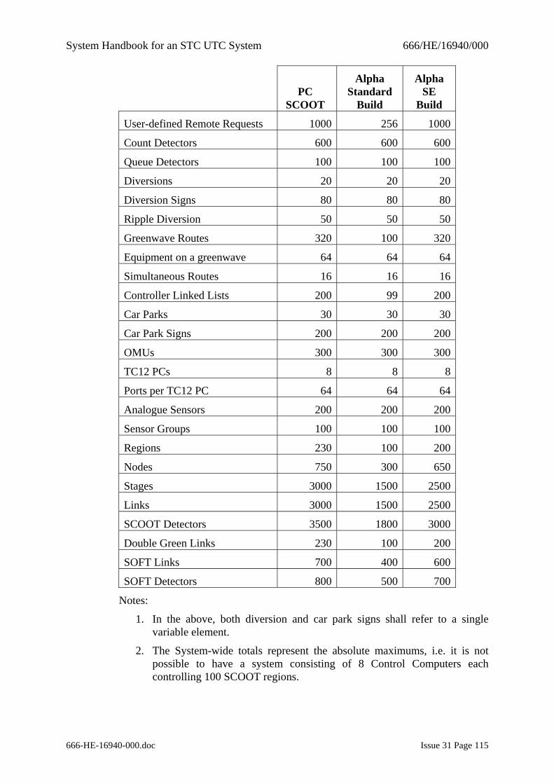
System Handbook for an STC UTC System 666/HE/16940/000
666-HE-16940-000.doc Issue 31 Page 115
PC
SCOOT
Alpha Standard
Build
Alpha SE
Build
User-defined Remote Requests 1000 256 1000
Count Detectors 600 600 600
Queue Detectors 100 100 100
Diversions 20 20 20
Diversion Signs 80 80 80
Ripple Diversion 50 50 50
Greenwave Routes 320 100 320
Equipment on a greenwave 64 64 64
Simultaneous Routes 16 16 16
Controller Linked Lists 200 99 200
Car Parks 30 30 30
Car Park Signs 200 200 200
OMUs 300 300 300
TC12 PCs 8 8 8
Ports per TC12 PC 64 64 64
Analogue Sensors 200 200 200
Sensor Groups 100 100 100
Regions 230 100 200
Nodes 750 300 650
Stages 3000 1500 2500
Links 3000 1500 2500
SCOOT Detectors 3500 1800 3000
Double Green Links 230 100 200
SOFT Links 700 400 600
SOFT Detectors 800 500 700
Notes:
1. In the above, both diversion and car park signs shall refer to a single variable element.
2. The System-wide totals represent the absolute maximums, i.e. it is not possible to have a system consisting of 8 Control Computers each controlling 100 SCOOT regions.

System Handbook for an STC UTC System 666/HE/16940/000
666-HE-16940-000.doc Issue 31 Page 116
3. The exact number of equipments controllable by a particular hardware configuration shall depend on the processor power and shall be defined in the UTC System's CRS.
4. The maximum number of SCOOT nodes which may be controlled by a UTC System is set by the number of licenced SCOOT nodes rather than System capacity.
System Handbook for an STC UTC System 666/HE/16940/000
666-HE-16940-000.doc Issue 31 Page 117
Appendix E - Open Source Software Copyright / License Declarations
The UTC software uses a number of open source software packages. This section contains reproductions of the licenses/copyright notices for these products. InfoZip This is version 2007-Mar-4 of the Info-ZIP license. The definitive version of this document should be available at ftp://ftp.info-zip.org/pub/infozip/license.html indefinitely and a copy at http://www.info-zip.org/pub/infozip/license.html. Copyright (c) 1990-2007 Info-ZIP. All rights reserved. For the purposes of this copyright and license, "Info-ZIP" is defined as the following set of individuals: Mark Adler, John Bush, Karl Davis, Harald Denker, Jean-Michel Dubois, Jean-loup Gailly, Hunter Goatley, Ed Gordon, Ian Gorman, Chris Herborth, Dirk Haase, Greg Hartwig, Robert Heath, Jonathan Hudson, Paul Kienitz, David Kirschbaum, Johnny Lee, Onno van der Linden, Igor Mandrichenko, Steve P. Miller, Sergio Monesi, Keith Owens, George Petrov, Greg Roelofs, Kai Uwe Rommel, Steve Salisbury, Dave Smith, Steven M. Schweda, Christian Spieler, Cosmin Truta, Antoine Verheijen, Paul von Behren, Rich Wales, Mike White. This software is provided "as is," without warranty of any kind, express or implied. In no event shall Info-ZIP or its contributors be held liable for any direct, indirect, incidental, special or consequential damages arising out of the use of or inability to use this software. Permission is granted to anyone to use this software for any purpose, including commercial applications, and to alter it and redistribute it freely, subject to the above disclaimer and the following restrictions: 1. Redistributions of source code (in whole or in part) must retain the above copyright notice, definition, disclaimer, and this list of conditions. 2. Redistributions in binary form (compiled executables and libraries) must reproduce the above copyright notice, definition, disclaimer, and this list of conditions in documentation and/or other materials provided with the distribution. The sole exception to this condition is redistribution of a standard UnZipSFX binary (including SFXWiz) as part of a self-extracting archive; that is permitted without inclusion of this license, as long as the normal SFX banner has not been removed from the binary or disabled. 3. Altered versions--including, but not limited to, ports to new operating systems, existing ports with new graphical interfaces, versions with modified or added functionality, and dynamic, shared, or static library versions not from Info-ZIP--must be plainly marked as such and must not be misrepresented as being the original source or, if binaries, compiled from the original source. Such altered versions also must not be misrepresented as being Info-ZIP releases--including, but not limited to, labeling of the altered versions with the names "Info-ZIP"
System Handbook for an STC UTC System 666/HE/16940/000
666-HE-16940-000.doc Issue 31 Page 118
(or any variation thereof, including, but not limited to, different capitalizations), "Pocket UnZip," "WiZ" or "MacZip" without the explicit permission of Info-ZIP. Such altered versions are further prohibited from misrepresentative use of the Zip-Bugs or Info-ZIP e-mail addresses or the Info-ZIP URL(s), such as to imply Info-ZIP will provide support for the altered versions. 4. Info-ZIP retains the right to use the names "Info-ZIP," "Zip," "UnZip," "UnZipSFX," "WiZ," "Pocket UnZip," "Pocket Zip," and "MacZip" for its own source and binary releases. Net-SNMP License Various copyrights apply to this package, listed in various separate parts below. Please make sure that you read all the parts. ---- Part 1: CMU/UCD copyright notice: (BSD like) ----- Copyright 1989, 1991, 1992 by Carnegie Mellon University Derivative Work - 1996, 1998-2000 Copyright 1996, 1998-2000 The Regents of the University of California All Rights Reserved Permission to use, copy, modify and distribute this software and its documentation for any purpose and without fee is hereby granted, provided that the above copyright notice appears in all copies and that both that copyright notice and this permission notice appear in supporting documentation, and that the name of CMU and The Regents of the University of California not be used in advertising or publicity pertaining to distribution of the software without specific written permission. CMU AND THE REGENTS OF THE UNIVERSITY OF CALIFORNIA DISCLAIM ALL WARRANTIES WITH REGARD TO THIS SOFTWARE, INCLUDING ALL IMPLIED WARRANTIES OF MERCHANTABILITY AND FITNESS. IN NO EVENT SHALL CMU OR THE REGENTS OF THE UNIVERSITY OF CALIFORNIA BE LIABLE FOR ANY SPECIAL, INDIRECT OR CONSEQUENTIAL DAMAGES OR ANY DAMAGES WHATSOEVER RESULTING FROM THE LOSS OF USE, DATA OR PROFITS, WHETHER IN AN ACTION OF CONTRACT, NEGLIGENCE OR OTHER TORTIOUS ACTION, ARISING OUT OF OR IN CONNECTION WITH THE USE OR PERFORMANCE OF THIS SOFTWARE. ---- Part 2: Networks Associates Technology, Inc copyright notice (BSD) ----- Copyright (c) 2001-2003, Networks Associates Technology, Inc All rights reserved. Redistribution and use in source and binary forms, with or without modification, are permitted provided that the following conditions are met: * Redistributions of source code must retain the above copyright notice, this list of conditions and the following disclaimer. * Redistributions in binary form must reproduce the above copyright notice, this list of conditions and the following disclaimer in the documentation and/or other materials provided with the distribution.
System Handbook for an STC UTC System 666/HE/16940/000
666-HE-16940-000.doc Issue 31 Page 119
* Neither the name of the Networks Associates Technology, Inc nor the names of its contributors may be used to endorse or promote products derived from this software without specific prior written permission. THIS SOFTWARE IS PROVIDED BY THE COPYRIGHT HOLDERS AND CONTRIBUTORS ``AS IS'' AND ANY EXPRESS OR IMPLIED WARRANTIES, INCLUDING, BUT NOT LIMITED TO, THE IMPLIED WARRANTIES OF MERCHANTABILITY AND FITNESS FOR A PARTICULAR PURPOSE ARE DISCLAIMED. IN NO EVENT SHALL THE COPYRIGHT HOLDERS OR CONTRIBUTORS BE LIABLE FOR ANY DIRECT, INDIRECT, INCIDENTAL, SPECIAL, EXEMPLARY, OR CONSEQUENTIAL DAMAGES (INCLUDING, BUT NOT LIMITED TO, PROCUREMENT OF SUBSTITUTE GOODS OR SERVICES; LOSS OF USE, DATA, OR PROFITS; OR BUSINESS INTERRUPTION) HOWEVER CAUSED AND ON ANY THEORY OF LIABILITY, WHETHER IN CONTRACT, STRICT LIABILITY, OR TORT (INCLUDING NEGLIGENCE OR OTHERWISE) ARISING IN ANY WAY OUT OF THE USE OF THIS SOFTWARE, EVEN IF ADVISED OF THE POSSIBILITY OF SUCH DAMAGE. ---- Part 3: Cambridge Broadband Ltd. copyright notice (BSD) ----- Portions of this code are copyright (c) 2001-2003, Cambridge Broadband Ltd. All rights reserved. Redistribution and use in source and binary forms, with or without modification, are permitted provided that the following conditions are met: * Redistributions of source code must retain the above copyright notice, this list of conditions and the following disclaimer. * Redistributions in binary form must reproduce the above copyright notice, this list of conditions and the following disclaimer in the documentation and/or other materials provided with the distribution. * The name of Cambridge Broadband Ltd. may not be used to endorse or promote products derived from this software without specific prior written permission. THIS SOFTWARE IS PROVIDED BY THE COPYRIGHT HOLDER ``AS IS'' AND ANY EXPRESS OR IMPLIED WARRANTIES, INCLUDING, BUT NOT LIMITED TO, THE IMPLIED WARRANTIES OF MERCHANTABILITY AND FITNESS FOR A PARTICULAR PURPOSE ARE DISCLAIMED. IN NO EVENT SHALL THE COPYRIGHT HOLDER BE LIABLE FOR ANY DIRECT, INDIRECT, INCIDENTAL, SPECIAL, EXEMPLARY, OR CONSEQUENTIAL DAMAGES (INCLUDING, BUT NOT LIMITED TO, PROCUREMENT OF SUBSTITUTE GOODS OR SERVICES; LOSS OF USE, DATA, OR PROFITS; OR BUSINESS INTERRUPTION) HOWEVER CAUSED AND ON ANY THEORY OF LIABILITY, WHETHER IN CONTRACT, STRICT LIABILITY, OR TORT (INCLUDING NEGLIGENCE OR OTHERWISE) ARISING IN ANY WAY OUT OF THE USE OF THIS SOFTWARE, EVEN IF ADVISED OF THE POSSIBILITY OF SUCH DAMAGE. ---- Part 4: Sun Microsystems, Inc. copyright notice (BSD) ----- Copyright © 2003 Sun Microsystems, Inc., 4150 Network Circle, Santa Clara, California 95054, U.S.A. All rights reserved. Use is subject to license terms below. This distribution may include materials developed by third parties. Sun, Sun Microsystems, the Sun logo and Solaris are trademarks or registered
System Handbook for an STC UTC System 666/HE/16940/000
666-HE-16940-000.doc Issue 31 Page 120
trademarks of Sun Microsystems, Inc. in the U.S. and other countries. Redistribution and use in source and binary forms, with or without modification, are permitted provided that the following conditions are met: * Redistributions of source code must retain the above copyright notice, this list of conditions and the following disclaimer. * Redistributions in binary form must reproduce the above copyright notice, this list of conditions and the following disclaimer in the documentation and/or other materials provided with the distribution. * Neither the name of the Sun Microsystems, Inc. nor the names of its contributors may be used to endorse or promote products derived from this software without specific prior written permission. THIS SOFTWARE IS PROVIDED BY THE COPYRIGHT HOLDERS AND CONTRIBUTORS ``AS IS'' AND ANY EXPRESS OR IMPLIED WARRANTIES, INCLUDING, BUT NOT LIMITED TO, THE IMPLIED WARRANTIES OF MERCHANTABILITY AND FITNESS FOR A PARTICULAR PURPOSE ARE DISCLAIMED. IN NO EVENT SHALL THE COPYRIGHT HOLDERS OR CONTRIBUTORS BE LIABLE FOR ANY DIRECT, INDIRECT, INCIDENTAL, SPECIAL, EXEMPLARY, OR CONSEQUENTIAL DAMAGES (INCLUDING, BUT NOT LIMITED TO, PROCUREMENT OF SUBSTITUTE GOODS OR SERVICES; LOSS OF USE, DATA, OR PROFITS; OR BUSINESS INTERRUPTION) HOWEVER CAUSED AND ON ANY THEORY OF LIABILITY, WHETHER IN CONTRACT, STRICT LIABILITY, OR TORT (INCLUDING NEGLIGENCE OR OTHERWISE) ARISING IN ANY WAY OUT OF THE USE OF THIS SOFTWARE, EVEN IF ADVISED OF THE POSSIBILITY OF SUCH DAMAGE. ---- Part 5: Sparta, Inc copyright notice (BSD) ----- Copyright (c) 2003-2008, Sparta, Inc All rights reserved. Redistribution and use in source and binary forms, with or without modification, are permitted provided that the following conditions are met: * Redistributions of source code must retain the above copyright notice, this list of conditions and the following disclaimer. * Redistributions in binary form must reproduce the above copyright notice, this list of conditions and the following disclaimer in the documentation and/or other materials provided with the distribution. * Neither the name of Sparta, Inc nor the names of its contributors may be used to endorse or promote products derived from this software without specific prior written permission. THIS SOFTWARE IS PROVIDED BY THE COPYRIGHT HOLDERS AND CONTRIBUTORS ``AS IS'' AND ANY EXPRESS OR IMPLIED WARRANTIES, INCLUDING, BUT NOT LIMITED TO, THE IMPLIED WARRANTIES OF MERCHANTABILITY AND FITNESS FOR A PARTICULAR PURPOSE ARE DISCLAIMED. IN NO EVENT SHALL THE COPYRIGHT HOLDERS OR CONTRIBUTORS BE LIABLE FOR ANY DIRECT, INDIRECT, INCIDENTAL, SPECIAL, EXEMPLARY, OR CONSEQUENTIAL DAMAGES (INCLUDING, BUT NOT LIMITED TO, PROCUREMENT OF SUBSTITUTE GOODS OR SERVICES; LOSS OF USE, DATA, OR PROFITS; OR BUSINESS INTERRUPTION) HOWEVER CAUSED AND ON ANY THEORY OF LIABILITY, WHETHER IN CONTRACT, STRICT LIABILITY, OR TORT (INCLUDING NEGLIGENCE OR OTHERWISE) ARISING IN ANY WAY OUT OF THE USE OF THIS SOFTWARE, EVEN IF ADVISED OF THE POSSIBILITY OF SUCH DAMAGE.
System Handbook for an STC UTC System 666/HE/16940/000
666-HE-16940-000.doc Issue 31 Page 121
---- Part 6: Cisco/BUPTNIC copyright notice (BSD) ----- Copyright (c) 2004, Cisco, Inc and Information Network Center of Beijing University of Posts and Telecommunications. All rights reserved. Redistribution and use in source and binary forms, with or without modification, are permitted provided that the following conditions are met: * Redistributions of source code must retain the above copyright notice, this list of conditions and the following disclaimer. * Redistributions in binary form must reproduce the above copyright notice, this list of conditions and the following disclaimer in the documentation and/or other materials provided with the distribution. * Neither the name of Cisco, Inc, Beijing University of Posts and Telecommunications, nor the names of their contributors may be used to endorse or promote products derived from this software without specific prior written permission. THIS SOFTWARE IS PROVIDED BY THE COPYRIGHT HOLDERS AND CONTRIBUTORS ``AS IS'' AND ANY EXPRESS OR IMPLIED WARRANTIES, INCLUDING, BUT NOT LIMITED TO, THE IMPLIED WARRANTIES OF MERCHANTABILITY AND FITNESS FOR A PARTICULAR PURPOSE ARE DISCLAIMED. IN NO EVENT SHALL THE COPYRIGHT HOLDERS OR CONTRIBUTORS BE LIABLE FOR ANY DIRECT, INDIRECT, INCIDENTAL, SPECIAL, EXEMPLARY, OR CONSEQUENTIAL DAMAGES (INCLUDING, BUT NOT LIMITED TO, PROCUREMENT OF SUBSTITUTE GOODS OR SERVICES; LOSS OF USE, DATA, OR PROFITS; OR BUSINESS INTERRUPTION) HOWEVER CAUSED AND ON ANY THEORY OF LIABILITY, WHETHER IN CONTRACT, STRICT LIABILITY, OR TORT (INCLUDING NEGLIGENCE OR OTHERWISE) ARISING IN ANY WAY OUT OF THE USE OF THIS SOFTWARE, EVEN IF ADVISED OF THE POSSIBILITY OF SUCH DAMAGE. ---- Part 7: Fabasoft R&D Software GmbH & Co KG copyright notice (BSD) ----- Copyright (c) Fabasoft R&D Software GmbH & Co KG, 2003 [email protected] Author: Bernhard Penz Redistribution and use in source and binary forms, with or without modification, are permitted provided that the following conditions are met: * Redistributions of source code must retain the above copyright notice, this list of conditions and the following disclaimer. * Redistributions in binary form must reproduce the above copyright notice, this list of conditions and the following disclaimer in the documentation and/or other materials provided with the distribution. * The name of Fabasoft R&D Software GmbH & Co KG or any of its subsidiaries, brand or product names may not be used to endorse or promote products derived from this software without specific prior written permission. THIS SOFTWARE IS PROVIDED BY THE COPYRIGHT HOLDER ``AS IS'' AND ANY EXPRESS OR IMPLIED WARRANTIES, INCLUDING, BUT NOT LIMITED TO, THE IMPLIED WARRANTIES OF MERCHANTABILITY AND FITNESS FOR A PARTICULAR PURPOSE ARE DISCLAIMED. IN NO EVENT SHALL THE COPYRIGHT HOLDER BE LIABLE FOR ANY DIRECT, INDIRECT, INCIDENTAL, SPECIAL, EXEMPLARY, OR CONSEQUENTIAL DAMAGES (INCLUDING, BUT NOT LIMITED TO, PROCUREMENT OF SUBSTITUTE GOODS OR SERVICES; LOSS OF USE, DATA, OR PROFITS; OR
System Handbook for an STC UTC System 666/HE/16940/000
666-HE-16940-000.doc Issue 31 Page 122
BUSINESS INTERRUPTION) HOWEVER CAUSED AND ON ANY THEORY OF LIABILITY, WHETHER IN CONTRACT, STRICT LIABILITY, OR TORT (INCLUDING NEGLIGENCE OR OTHERWISE) ARISING IN ANY WAY OUT OF THE USE OF THIS SOFTWARE, EVEN IF ADVISED OF THE POSSIBILITY OF SUCH DAMAGE. Expat Copyright (c) 1998, 1999, 2000 Thai Open Source Software Center Ltd and Clark Cooper Copyright (c) 2001, 2002, 2003, 2004, 2005, 2006 Expat maintainers. Permission is hereby granted, free of charge, to any person obtaining a copy of this software and associated documentation files (the "Software"), to deal in the Software without restriction, including without limitation the rights to use, copy, modify, merge, publish, distribute, sublicense, and/or sell copies of the Software, and to permit persons to whom the Software is furnished to do so, subject to the following conditions: The above copyright notice and this permission notice shall be included in all copies or substantial portions of the Software. THE SOFTWARE IS PROVIDED "AS IS", WITHOUT WARRANTY OF ANY KIND, EXPRESS OR IMPLIED, INCLUDING BUT NOT LIMITED TO THE WARRANTIES OF MERCHANTABILITY, FITNESS FOR A PARTICULAR PURPOSE AND NONINFRINGEMENT. IN NO EVENT SHALL THE AUTHORS OR COPYRIGHT HOLDERS BE LIABLE FOR ANY CLAIM, DAMAGES OR OTHER LIABILITY, WHETHER IN AN ACTION OF CONTRACT, TORT OR OTHERWISE, ARISING FROM, OUT OF OR IN CONNECTION WITH THE SOFTWARE OR THE USE OR OTHER DEALINGS IN THE SOFTWARE. OpenSSL LICENSE ISSUES ============== The OpenSSL toolkit stays under a dual license, i.e. both the conditions of the OpenSSL License and the original SSLeay license apply to the toolkit. See below for the actual license texts. Actually both licenses are BSD-style Open Source licenses. In case of any license issues related to OpenSSL please contact [email protected]. OpenSSL License --------------- /* ==================================================================== * Copyright (c) 1998-2008 The OpenSSL Project. All rights reserved. * * Redistribution and use in source and binary forms, with or without * modification, are permitted provided that the following conditions * are met: * * 1. Redistributions of source code must retain the above copyright * notice, this list of conditions and the following disclaimer. * * 2. Redistributions in binary form must reproduce the above copyright * notice, this list of conditions and the following disclaimer in * the documentation and/or other materials provided with the * distribution. *
System Handbook for an STC UTC System 666/HE/16940/000
666-HE-16940-000.doc Issue 31 Page 123
* 3. All advertising materials mentioning features or use of this * software must display the following acknowledgment: * "This product includes software developed by the OpenSSL Project * for use in the OpenSSL Toolkit. (http://www.openssl.org/)" * * 4. The names "OpenSSL Toolkit" and "OpenSSL Project" must not be used to * endorse or promote products derived from this software without * prior written permission. For written permission, please contact * [email protected]. * * 5. Products derived from this software may not be called "OpenSSL" * nor may "OpenSSL" appear in their names without prior written * permission of the OpenSSL Project. * * 6. Redistributions of any form whatsoever must retain the following * acknowledgment: * "This product includes software developed by the OpenSSL Project * for use in the OpenSSL Toolkit (http://www.openssl.org/)" * * THIS SOFTWARE IS PROVIDED BY THE OpenSSL PROJECT ``AS IS'' AND ANY * EXPRESSED OR IMPLIED WARRANTIES, INCLUDING, BUT NOT LIMITED TO, THE * IMPLIED WARRANTIES OF MERCHANTABILITY AND FITNESS FOR A PARTICULAR * PURPOSE ARE DISCLAIMED. IN NO EVENT SHALL THE OpenSSL PROJECT OR * ITS CONTRIBUTORS BE LIABLE FOR ANY DIRECT, INDIRECT, INCIDENTAL, * SPECIAL, EXEMPLARY, OR CONSEQUENTIAL DAMAGES (INCLUDING, BUT * NOT LIMITED TO, PROCUREMENT OF SUBSTITUTE GOODS OR SERVICES; * LOSS OF USE, DATA, OR PROFITS; OR BUSINESS INTERRUPTION) * HOWEVER CAUSED AND ON ANY THEORY OF LIABILITY, WHETHER IN CONTRACT, * STRICT LIABILITY, OR TORT (INCLUDING NEGLIGENCE OR OTHERWISE) * ARISING IN ANY WAY OUT OF THE USE OF THIS SOFTWARE, EVEN IF ADVISED * OF THE POSSIBILITY OF SUCH DAMAGE. * ==================================================================== * * This product includes cryptographic software written by Eric Young * ([email protected]). This product includes software written by Tim * Hudson ([email protected]). * */ Original SSLeay License ----------------------- /* Copyright (C) 1995-1998 Eric Young ([email protected]) * All rights reserved. * * This package is an SSL implementation written * by Eric Young ([email protected]). * The implementation was written so as to conform with Netscapes SSL. * * This library is free for commercial and non-commercial use as long as * the following conditions are aheared to. The following conditions * apply to all code found in this distribution, be it the RC4, RSA, * lhash, DES, etc., code; not just the SSL code. The SSL documentation * included with this distribution is covered by the same copyright terms * except that the holder is Tim Hudson ([email protected]). * * Copyright remains Eric Young's, and as such any Copyright notices in * the code are not to be removed. * If this package is used in a product, Eric Young should be given attribution * as the author of the parts of the library used.
System Handbook for an STC UTC System 666/HE/16940/000
666-HE-16940-000.doc Issue 31 Page 124
* This can be in the form of a textual message at program startup or * in documentation (online or textual) provided with the package. * * Redistribution and use in source and binary forms, with or without * modification, are permitted provided that the following conditions * are met: * 1. Redistributions of source code must retain the copyright * notice, this list of conditions and the following disclaimer. * 2. Redistributions in binary form must reproduce the above copyright * notice, this list of conditions and the following disclaimer in the * documentation and/or other materials provided with the distribution. * 3. All advertising materials mentioning features or use of this software * must display the following acknowledgement: * "This product includes cryptographic software written by * Eric Young ([email protected])" * The word 'cryptographic' can be left out if the rouines from the library * being used are not cryptographic related :-). * 4. If you include any Windows specific code (or a derivative thereof) from * the apps directory (application code) you must include an acknowledgement: * "This product includes software written by Tim Hudson ([email protected])" * * THIS SOFTWARE IS PROVIDED BY ERIC YOUNG ``AS IS'' AND * ANY EXPRESS OR IMPLIED WARRANTIES, INCLUDING, BUT NOT LIMITED TO, THE * IMPLIED WARRANTIES OF MERCHANTABILITY AND FITNESS FOR A PARTICULAR PURPOSE * ARE DISCLAIMED. IN NO EVENT SHALL THE AUTHOR OR CONTRIBUTORS BE LIABLE * FOR ANY DIRECT, INDIRECT, INCIDENTAL, SPECIAL, EXEMPLARY, OR CONSEQUENTIAL * DAMAGES (INCLUDING, BUT NOT LIMITED TO, PROCUREMENT OF SUBSTITUTE GOODS * OR SERVICES; LOSS OF USE, DATA, OR PROFITS; OR BUSINESS INTERRUPTION) * HOWEVER CAUSED AND ON ANY THEORY OF LIABILITY, WHETHER IN CONTRACT, STRICT * LIABILITY, OR TORT (INCLUDING NEGLIGENCE OR OTHERWISE) ARISING IN ANY WAY * OUT OF THE USE OF THIS SOFTWARE, EVEN IF ADVISED OF THE POSSIBILITY OF * SUCH DAMAGE. * * The licence and distribution terms for any publically available version or * derivative of this code cannot be changed. i.e. this code cannot simply be * copied and put under another distribution licence * [including the GNU Public Licence.] */ Telnetd Telnet daemon. /* * Copyright (c) 1989 Regents of the University of California. * All rights reserved. * * Redistribution and use in source and binary forms, with or without * modification, are permitted provided that the following conditions * are met: * 1. Redistributions of source code must retain the above copyright * notice, this list of conditions and the following disclaimer. * 2. Redistributions in binary form must reproduce the above copyright * notice, this list of conditions and the following disclaimer in the * documentation and/or other materials provided with the distribution. * 3. All advertising materials mentioning features or use of this software * must display the following acknowledgement: * This product includes software developed by the University of * California, Berkeley and its contributors. * 4. Neither the name of the University nor the names of its contributors
System Handbook for an STC UTC System 666/HE/16940/000
666-HE-16940-000.doc Issue 31 Page 125
* may be used to endorse or promote products derived from this software * without specific prior written permission. * * THIS SOFTWARE IS PROVIDED BY THE REGENTS AND CONTRIBUTORS ``AS IS'' AND * ANY EXPRESS OR IMPLIED WARRANTIES, INCLUDING, BUT NOT LIMITED TO, THE * IMPLIED WARRANTIES OF MERCHANTABILITY AND FITNESS FOR A PARTICULAR PURPOSE * ARE DISCLAIMED. IN NO EVENT SHALL THE REGENTS OR CONTRIBUTORS BE LIABLE * FOR ANY DIRECT, INDIRECT, INCIDENTAL, SPECIAL, EXEMPLARY, OR CONSEQUENTIAL * DAMAGES (INCLUDING, BUT NOT LIMITED TO, PROCUREMENT OF SUBSTITUTE GOODS * OR SERVICES; LOSS OF USE, DATA, OR PROFITS; OR BUSINESS INTERRUPTION) * HOWEVER CAUSED AND ON ANY THEORY OF LIABILITY, WHETHER IN CONTRACT, STRICT * LIABILITY, OR TORT (INCLUDING NEGLIGENCE OR OTHERWISE) ARISING IN ANY WAY * OUT OF THE USE OF THIS SOFTWARE, EVEN IF ADVISED OF THE POSSIBILITY OF * SUCH DAMAGE. */ WinPcap License Copyright (c) 1999 - 2005 NetGroup, Politecnico di Torino (Italy). Copyright (c) 2005 - 2009 CACE Technologies, Davis (California). All rights reserved. Redistribution and use in source and binary forms, with or without modification, are permitted provided that the following conditions are met: 1. Redistributions of source code must retain the above copyright notice, this list of conditions and the following disclaimer. 2. Redistributions in binary form must reproduce the above copyright notice, this list of conditions and the following disclaimer in the documentation and/or other materials provided with the distribution. 3. Neither the name of the Politecnico di Torino, CACE Technologies nor the names of its contributors may be used to endorse or promote products derived from this software without specific prior written permission. THIS SOFTWARE IS PROVIDED BY THE COPYRIGHT HOLDERS AND CONTRIBUTORS "AS IS" AND ANY EXPRESS OR IMPLIED WARRANTIES, INCLUDING, BUT NOT LIMITED TO, THE IMPLIED WARRANTIES OF MERCHANTABILITY AND FITNESS FOR A PARTICULAR PURPOSE ARE DISCLAIMED. IN NO EVENT SHALL THE COPYRIGHT OWNER OR CONTRIBUTORS BE LIABLE FOR ANY DIRECT, INDIRECT, INCIDENTAL, SPECIAL, EXEMPLARY, OR CONSEQUENTIAL DAMAGES (INCLUDING, BUT NOT LIMITED TO, PROCUREMENT OF SUBSTITUTE GOODS OR SERVICES; LOSS OF USE, DATA, OR PROFITS; OR BUSINESS INTERRUPTION) HOWEVER CAUSED AND ON ANY THEORY OF LIABILITY, WHETHER IN CONTRACT, STRICT LIABILITY, OR TORT (INCLUDING NEGLIGENCE OR OTHERWISE) ARISING IN ANY WAY OUT OF THE USE OF THIS SOFTWARE, EVEN IF ADVISED OF THE POSSIBILITY OF SUCH DAMAGE. This product includes software developed by the University of California, Lawrence Berkeley Laboratory and its contributors. This product includes software developed by the Kungliga Tekniska Högskolan and its contributors. This product includes software developed by Yen Yen Lim and North Dakota State University. Portions Copyright (c) 1990, 1991, 1992, 1993, 1994, 1995, 1996, 1997 The Regents of the University of California. All rights reserved. Redistribution and use in source and binary forms, with or without modification, are permitted provided that the following conditions are met: 1. Redistributions of source code must retain the above copyright notice, this list of conditions and the following disclaimer.
System Handbook for an STC UTC System 666/HE/16940/000
666-HE-16940-000.doc Issue 31 Page 126
2. Redistributions in binary form must reproduce the above copyright notice, this list of conditions and the following disclaimer in the documentation and/or other materials provided with the distribution. 3. All advertising materials mentioning features or use of this software must display the following acknowledgement: "This product includes software developed by the University of California, Berkeley and its contributors." 4. Neither the name of the University nor the names of its contributors may be used to endorse or promote products derived from this software without specific prior written permission. THIS SOFTWARE IS PROVIDED BY THE INSTITUTE AND CONTRIBUTORS ``AS IS'' AND ANY EXPRESS OR IMPLIED WARRANTIES, INCLUDING, BUT NOT LIMITED TO, THE IMPLIED WARRANTIES OF MERCHANTABILITY AND FITNESS FOR A PARTICULAR PURPOSE ARE DISCLAIMED. IN NO EVENT SHALL THE REGENTS OR CONTRIBUTORS BE LIABLE FOR ANY DIRECT, INDIRECT, INCIDENTAL, SPECIAL, EXEMPLARY, OR CONSEQUENTIAL DAMAGES (INCLUDING, BUT NOT LIMITED TO, PROCUREMENT OF SUBSTITUTE GOODS OR SERVICES; LOSS OF USE, DATA, OR PROFITS; OR BUSINESS INTERRUPTION) HOWEVER CAUSED AND ON ANY THEORY OF LIABILITY, WHETHER IN CONTRACT, STRICT LIABILITY, OR TORT (INCLUDING NEGLIGENCE OR OTHERWISE) ARISING IN ANY WAY OUT OF THE USE OF THIS SOFTWARE, EVEN IF ADVISED OF THE POSSIBILITY OF SUCH DAMAGE. Portions Copyright (c) 1983 Regents of the University of California. All rights reserved. Redistribution and use in source and binary forms are permitted provided that the above copyright notice and this paragraph are duplicated in all such forms and that any documentation, advertising materials, and other materials related to such distribution and use acknowledge that the software was developed by the University of California, Berkeley. The name of the University may not be used to endorse or promote products derived from this software without specific prior written permission. THIS SOFTWARE IS PROVIDED ``AS IS'' AND WITHOUT ANY EXPRESS OR IMPLIED WARRANTIES, INCLUDING, WITHOUT LIMITATION, THE IMPLIED WARRANTIES OF MERCHANTIBILITY AND FITNESS FOR A PARTICULAR PURPOSE. Portions Copyright (c) 1995, 1996, 1997 Kungliga Tekniska Högskolan (Royal Institute of Technology, Stockholm, Sweden). All rights reserved. Redistribution and use in source and binary forms, with or without modification, are permitted provided that the following conditions are met: 1. Redistributions of source code must retain the above copyright notice, this list of conditions and the following disclaimer. 2. Redistributions in binary form must reproduce the above copyright notice, this list of conditions and the following disclaimer in the documentation and/or other materials provided with the distribution. 3. All advertising materials mentioning features or use of this software must display the following acknowledgement: "This product includes software developed by the Kungliga Tekniska Högskolan and its contributors." 4. Neither the name of the University nor the names of its contributors may be used to endorse or promote products derived from this software without specific prior written permission. THIS SOFTWARE IS PROVIDED BY THE INSTITUTE AND CONTRIBUTORS ``AS IS'' AND ANY EXPRESS OR IMPLIED WARRANTIES, INCLUDING, BUT NOT LIMITED TO, THE IMPLIED WARRANTIES OF MERCHANTABILITY AND FITNESS FOR A PARTICULAR PURPOSE ARE DISCLAIMED. IN NO EVENT SHALL THE INSTITUTE OR CONTRIBUTORS BE LIABLE FOR ANY DIRECT, INDIRECT, INCIDENTAL, SPECIAL, EXEMPLARY, OR CONSEQUENTIAL DAMAGES (INCLUDING, BUT NOT LIMITED TO, PROCUREMENT OF SUBSTITUTE GOODS OR SERVICES; LOSS OF USE, DATA, OR PROFITS; OR BUSINESS INTERRUPTION) HOWEVER CAUSED AND ON ANY THEORY OF LIABILITY, WHETHER IN CONTRACT, STRICT LIABILITY, OR TORT (INCLUDING NEGLIGENCE OR OTHERWISE) ARISING IN ANY WAY OUT OF THE USE OF THIS SOFTWARE, EVEN IF ADVISED OF THE POSSIBILITY OF SUCH DAMAGE. Portions Copyright (c) 1997 Yen Yen Lim and North Dakota State University. All rights reserved. Redistribution and use in source and binary forms, with or without modification, are permitted provided that the following conditions are met: 1. Redistributions of source code must retain the above copyright notice, this list of conditions and the following disclaimer. 2. Redistributions in binary form must reproduce the above copyright notice, this list of conditions and the following disclaimer in the documentation and/or other materials provided with the distribution.
System Handbook for an STC UTC System 666/HE/16940/000
666-HE-16940-000.doc Issue 31 Page 127
3. All advertising materials mentioning features or use of this software must display the following acknowledgement: "This product includes software developed by Yen Yen Lim and North Dakota State University" 4. The name of the author may not be used to endorse or promote products derived from this software without specific prior written permission. THIS SOFTWARE IS PROVIDED BY THE AUTHOR ``AS IS'' AND ANY EXPRESS OR IMPLIED WARRANTIES, INCLUDING, BUT NOT LIMITED TO, THE IMPLIED WARRANTIES OF MERCHANTABILITY AND FITNESS FOR A PARTICULAR PURPOSE ARE DISCLAIMED. IN NO EVENT SHALL THE AUTHOR BE LIABLE FOR ANY DIRECT, INDIRECT, INCIDENTAL, SPECIAL, EXEMPLARY, OR CONSEQUENTIAL DAMAGES (INCLUDING, BUT NOT LIMITED TO, PROCUREMENT OF SUBSTITUTE GOODS OR SERVICES; LOSS OF USE, DATA, OR PROFITS; OR BUSINESS INTERRUPTION) HOWEVER CAUSED AND ON ANY THEORY OF LIABILITY, WHETHER IN CONTRACT, STRICT LIABILITY, OR TORT (INCLUDING NEGLIGENCE OR OTHERWISE) ARISING IN ANY WAY OUT OF THE USE OF THIS SOFTWARE, EVEN IF ADVISED OF THE POSSIBILITY OF SUCH DAMAGE. Portions Copyright (c) 1993 by Digital Equipment Corporation. Permission to use, copy, modify, and distribute this software for any purpose with or without fee is hereby granted, provided that the above copyright notice and this permission notice appear in all copies, and that the name of Digital Equipment Corporation not be used in advertising or publicity pertaining to distribution of the document or software without specific, written prior permission. THE SOFTWARE IS PROVIDED "AS IS" AND DIGITAL EQUIPMENT CORP. DISCLAIMS ALL WARRANTIES WITH REGARD TO THIS SOFTWARE, INCLUDING ALL IMPLIED WARRANTIES OF MERCHANTABILITY AND FITNESS. IN NO EVENT SHALL DIGITAL EQUIPMENT CORPORATION BE LIABLE FOR ANY SPECIAL, DIRECT, INDIRECT, OR CONSEQUENTIAL DAMAGES OR ANY DAMAGES WHATSOEVER RESULTING FROM LOSS OF USE, DATA OR PROFITS, WHETHER IN AN ACTION OF CONTRACT, NEGLIGENCE OR OTHER TORTIOUS ACTION, ARISING OUT OF OR IN CONNECTION WITH THE USE OR PERFORMANCE OF THIS SOFTWARE. Portions Copyright (C) 1995, 1996, 1997, 1998, and 1999 WIDE Project. All rights reserved. Redistribution and use in source and binary forms, with or without modification, are permitted provided that the following conditions are met: 1. Redistributions of source code must retain the above copyright notice, this list of conditions and the following disclaimer. 2. Redistributions in binary form must reproduce the above copyright notice, this list of conditions and the following disclaimer in the documentation and/or other materials provided with the distribution. 3. Neither the name of the project nor the names of its contributors may be used to endorse or promote products derived from this software without specific prior written permission. THIS SOFTWARE IS PROVIDED BY THE PROJECT AND CONTRIBUTORS ``AS IS'' AND ANY EXPRESS OR IMPLIED WARRANTIES, INCLUDING, BUT NOT LIMITED TO, THE IMPLIED WARRANTIES OF MERCHANTABILITY AND FITNESS FOR A PARTICULAR PURPOSE ARE DISCLAIMED. IN NO EVENT SHALL THE PROJECT OR CONTRIBUTORS BE LIABLE FOR ANY DIRECT, INDIRECT, INCIDENTAL, SPECIAL, EXEMPLARY, OR CONSEQUENTIAL DAMAGES (INCLUDING, BUT NOT LIMITED TO, PROCUREMENT OF SUBSTITUTE GOODS OR SERVICES; LOSS OF USE, DATA, OR PROFITS; OR BUSINESS INTERRUPTION) HOWEVER CAUSED AND ON ANY THEORY OF LIABILITY, WHETHER IN CONTRACT, STRICT LIABILITY, OR TORT (INCLUDING NEGLIGENCE OR OTHERWISE) ARISING IN ANY WAY OUT OF THE USE OF THIS SOFTWARE, EVEN IF ADVISED OF THE POSSIBILITY OF SUCH DAMAGE. Portions Copyright (c) 1996 Juniper Networks, Inc. All rights reserved. Redistribution and use in source and binary forms, with or without modification, are permitted provided that: (1) source code distributions retain the above copyright notice and this paragraph in its entirety, (2) distributions including binary code include the above copyright notice and this paragraph in its entirety in the documentation or other materials provided with the distribution. The name of Juniper Networks may not be used to endorse or promote products derived from this software without specific prior written permission. THIS SOFTWARE IS PROVIDED ``AS IS'' AND WITHOUT ANY EXPRESS OR IMPLIED WARRANTIES, INCLUDING, WITHOUT LIMITATION, THE IMPLIED WARRANTIES OF MERCHANTABILITY AND FITNESS FOR A PARTICULAR PURPOSE. Portions Copyright (c) 2001 Daniel Hartmeier All rights reserved.
System Handbook for an STC UTC System 666/HE/16940/000
666-HE-16940-000.doc Issue 31 Page 128
Redistribution and use in source and binary forms, with or without modification, are permitted provided that the following conditions are met: - Redistributions of source code must retain the above copyright notice, this list of conditions and the following disclaimer. - Redistributions in binary form must reproduce the above copyright notice, this list of conditions and the following disclaimer in the documentation and/or other materials provided with the distribution. THIS SOFTWARE IS PROVIDED BY THE COPYRIGHT HOLDERS AND CONTRIBUTOR "AS IS" AND ANY EXPRESS OR IMPLIED WARRANTIES, INCLUDING, BUT NOT LIMITED TO, THE IMPLIED WARRANTIES OF MERCHANTABILITY AND FITNESS FOR A PARTICULAR PURPOSE ARE DISCLAIMED. IN NO EVENT SHALL THE COPYRIGHT HOLDERS OR CONTRIBUTORS BE LIABLE FOR ANY DIRECT, INDIRECT, INCIDENTAL, SPECIAL, EXEMPLARY, OR CONSEQUENTIAL DAMAGES (INCLUDING, BUT NOT LIMITED TO, PROCUREMENT OF SUBSTITUTE GOODS OR SERVICES; LOSS OF USE, DATA, OR PROFITS; OR BUSINESS INTERRUPTION) HOWEVER CAUSED AND ON ANY THEORY OF LIABILITY, WHETHER IN CONTRACT, STRICT LIABILITY, OR TORT (INCLUDING NEGLIGENCE OR OTHERWISE) ARISING IN ANY WAY OUT OF THE USE OF THIS SOFTWARE, EVEN IF ADVISED OF THE POSSIBILITY OF SUCH DAMAGE. Portions Copyright 1989 by Carnegie Mellon. Permission to use, copy, modify, and distribute this program for any purpose and without fee is hereby granted, provided that this copyright and permission notice appear on all copies and supporting documentation, the name of Carnegie Mellon not be used in advertising or publicity pertaining to distribution of the program without specific prior permission, and notice be given in supporting documentation that copying and distribution is by permission of Carnegie Mellon and Stanford University. Carnegie Mellon makes no representations about the suitability of this software for any purpose. It is provided "as is" without express or implied warranty. Xterm Copyright (c) 1987, 1988 X Consortium Permission is hereby granted, free of charge, to any person obtaining a copy of this software and associated documentation files (the "Software"), to deal in the Software without restriction, including without limitation the rights to use, copy, modify, merge, publish, distribute, sublicense, and/or sell copies of the Software, and to permit persons to whom the Software is furnished to do so, subject to the following conditions: The above copyright notice and this permission notice shall be included in all copies or substantial portions of the Software. THE SOFTWARE IS PROVIDED "AS IS", WITHOUT WARRANTY OF ANY KIND, EXPRESS OR IMPLIED, INCLUDING BUT NOT LIMITED TO THE WARRANTIES OF MERCHANTABILITY, FITNESS FOR A PARTICULAR PURPOSE AND NONINFRINGEMENT. IN NO EVENT SHALL THE X CONSORTIUM BE LIABLE FOR ANY CLAIM, DAMAGES OR OTHER LIABILITY, WHETHER IN AN ACTION OF CONTRACT, TORT OR OTHERWISE, ARISING FROM, OUT OF OR IN CONNECTION WITH THE SOFTWARE OR THE USE OR OTHER DEALINGS IN THE SOFTWARE. Except as contained in this notice, the name of the X Consortium shall not be used in advertising or otherwise to promote the sale, use or other dealings in this Software without prior written authorization from the X Consortium. Copyright 1987, 1988 by Digital Equipment Corporation, Maynard. All Rights Reserved Permission to use, copy, modify, and distribute this software and its
System Handbook for an STC UTC System 666/HE/16940/000
666-HE-16940-000.doc Issue 31 Page 129
documentation for any purpose and without fee is hereby granted, provided that the above copyright notice appear in all copies and that both that copyright notice and this permission notice appear in supporting documentation, and that the name of Digital not be used in advertising or publicity pertaining to distribution of the software without specific, written prior permission. DIGITAL DISCLAIMS ALL WARRANTIES WITH REGARD TO THIS SOFTWARE, INCLUDING ALL IMPLIED WARRANTIES OF MERCHANTABILITY AND FITNESS, IN NO EVENT SHALL DIGITAL BE LIABLE FOR ANY SPECIAL, INDIRECT OR CONSEQUENTIAL DAMAGES OR ANY DAMAGES WHATSOEVER RESULTING FROM LOSS OF USE, DATA OR PROFITS, WHETHER IN AN ACTION OF CONTRACT, NEGLIGENCE OR OTHER TORTIOUS ACTION, ARISING OUT OF OR IN CONNECTION WITH THE USE OR PERFORMANCE OF THIS SOFTWARE. OmniORB OmniORB is licensed under the GNU Lesser General Public License. http://www.gnu.org/licenses/lgpl.html OpenVMS Packages The following are used with OpenVMS versions of UTC only. Samba Samba is licensed under the GNU Public License. http://www.gnu.org/licenses/gpl.html Source code the GNU licensed software is available upon request. WASD Web Server WASD is licensed under the GNU Public License. http://www.gnu.org/licenses/gpl.html Source code the GNU licensed software is available upon request. GNU Ghostscript GNU Ghostscript is licensed under the GNU Public License. http://www.gnu.org/licenses/gpl.html Source code the GNU licensed software is available upon request.
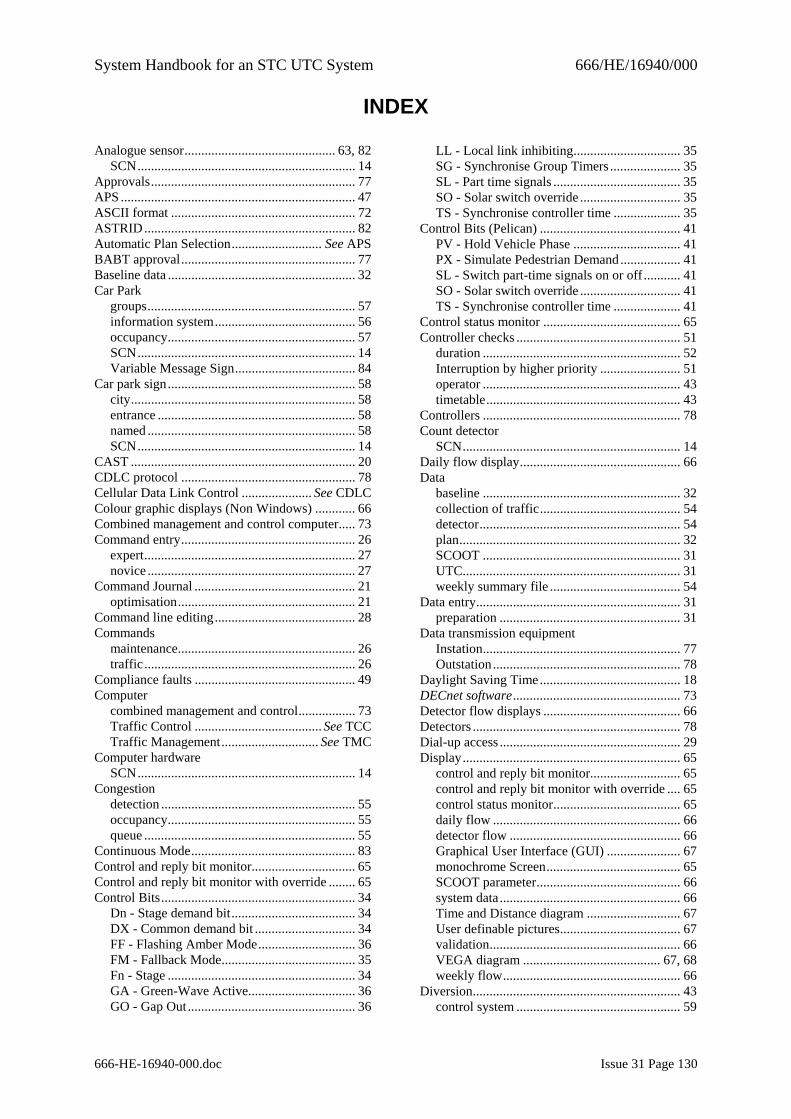
System Handbook for an STC UTC System 666/HE/16940/000
666-HE-16940-000.doc Issue 31 Page 130
INDEX
Analogue sensor............................................. 63, 82 SCN................................................................. 14
Approvals............................................................. 77 APS ...................................................................... 47 ASCII format ....................................................... 72 ASTRID............................................................... 82 Automatic Plan Selection........................... See APS BABT approval.................................................... 77 Baseline data ........................................................ 32 Car Park
groups.............................................................. 57 information system.......................................... 56 occupancy........................................................ 57 SCN................................................................. 14 Variable Message Sign.................................... 84
Car park sign........................................................ 58 city................................................................... 58 entrance ........................................................... 58 named .............................................................. 58 SCN................................................................. 14
CAST ................................................................... 20 CDLC protocol .................................................... 78 Cellular Data Link Control ..................... See CDLC Colour graphic displays (Non Windows) ............ 66 Combined management and control computer..... 73 Command entry.................................................... 26
expert............................................................... 27 novice .............................................................. 27
Command Journal ................................................ 21 optimisation..................................................... 21
Command line editing.......................................... 28 Commands
maintenance..................................................... 26 traffic ............................................................... 26
Compliance faults ................................................ 49 Computer
combined management and control................. 73 Traffic Control ...................................... See TCC Traffic Management............................. See TMC
Computer hardware SCN................................................................. 14
Congestion detection .......................................................... 55 occupancy........................................................ 55 queue ............................................................... 55
Continuous Mode................................................. 83 Control and reply bit monitor............................... 65 Control and reply bit monitor with override ........ 65 Control Bits.......................................................... 34
Dn - Stage demand bit..................................... 34 DX - Common demand bit .............................. 34 FF - Flashing Amber Mode............................. 36 FM - Fallback Mode........................................ 35 Fn - Stage ........................................................ 34 GA - Green-Wave Active................................ 36 GO - Gap Out.................................................. 36
LL - Local link inhibiting................................ 35 SG - Synchronise Group Timers ..................... 35 SL - Part time signals ...................................... 35 SO - Solar switch override .............................. 35 TS - Synchronise controller time .................... 35
Control Bits (Pelican) .......................................... 41 PV - Hold Vehicle Phase ................................ 41 PX - Simulate Pedestrian Demand .................. 41 SL - Switch part-time signals on or off ........... 41 SO - Solar switch override .............................. 41 TS - Synchronise controller time .................... 41
Control status monitor ......................................... 65 Controller checks ................................................. 51
duration ........................................................... 52 Interruption by higher priority ........................ 51 operator ........................................................... 43 timetable.......................................................... 43
Controllers ........................................................... 78 Count detector
SCN................................................................. 14 Daily flow display................................................ 66 Data
baseline ........................................................... 32 collection of traffic.......................................... 54 detector............................................................ 54 plan.................................................................. 32 SCOOT ........................................................... 31 UTC................................................................. 31 weekly summary file ....................................... 54
Data entry............................................................. 31 preparation ...................................................... 31
Data transmission equipment Instation........................................................... 77 Outstation........................................................ 78
Daylight Saving Time.......................................... 18 DECnet software.................................................. 73 Detector flow displays ......................................... 66 Detectors .............................................................. 78 Dial-up access ...................................................... 29 Display................................................................. 65
control and reply bit monitor........................... 65 control and reply bit monitor with override .... 65 control status monitor...................................... 65 daily flow ........................................................ 66 detector flow ................................................... 66 Graphical User Interface (GUI) ...................... 67 monochrome Screen........................................ 65 SCOOT parameter........................................... 66 system data...................................................... 66 Time and Distance diagram ............................ 67 User definable pictures.................................... 67 validation......................................................... 66 VEGA diagram ......................................... 67, 68 weekly flow..................................................... 66
Diversion.............................................................. 43 control system ................................................. 59
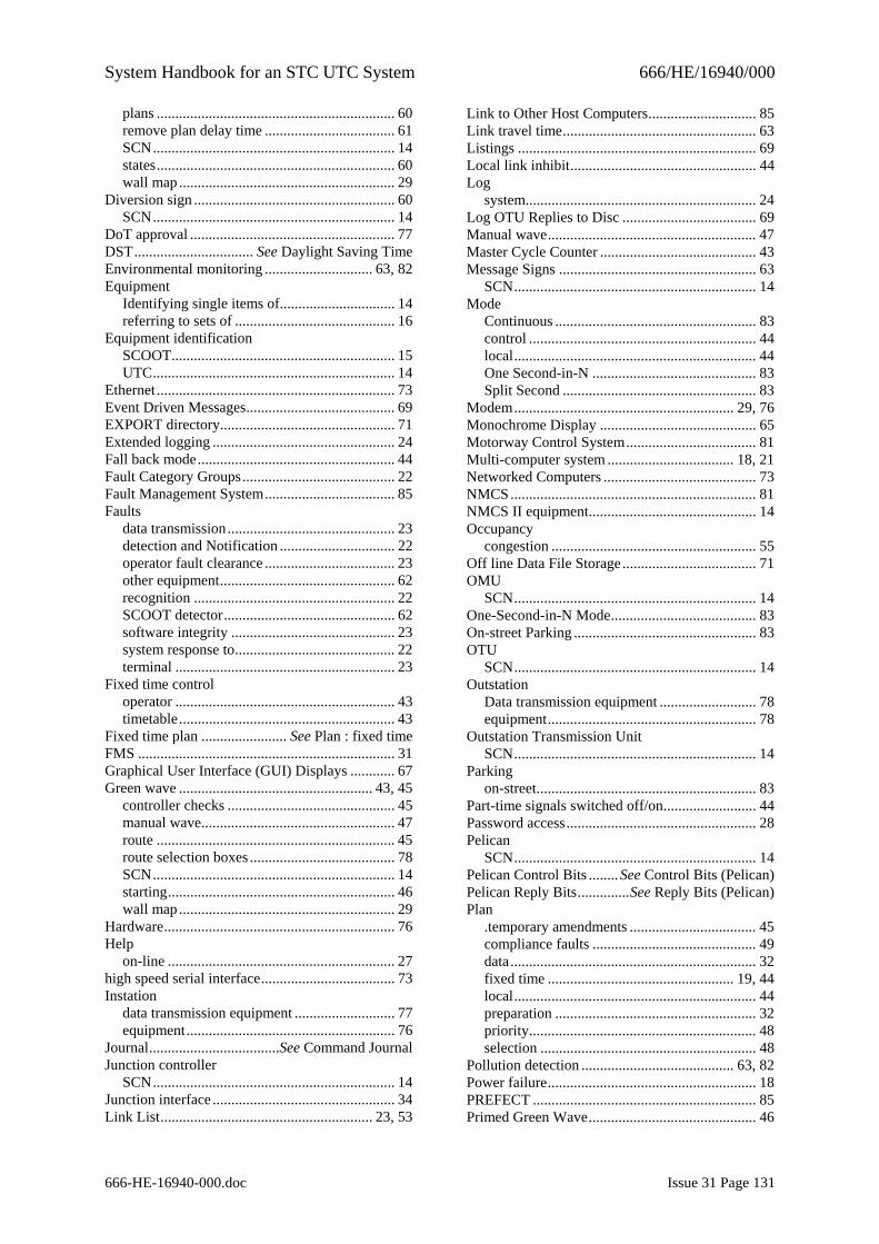
System Handbook for an STC UTC System 666/HE/16940/000
666-HE-16940-000.doc Issue 31 Page 131
plans ................................................................ 60 remove plan delay time ................................... 61 SCN................................................................. 14 states................................................................ 60 wall map .......................................................... 29
Diversion sign ...................................................... 60 SCN................................................................. 14
DoT approval ....................................................... 77 DST................................ See Daylight Saving Time Environmental monitoring ............................. 63, 82 Equipment
Identifying single items of............................... 14 referring to sets of ........................................... 16
Equipment identification SCOOT............................................................ 15 UTC................................................................. 14
Ethernet ................................................................ 73 Event Driven Messages........................................ 69 EXPORT directory............................................... 71 Extended logging ................................................. 24 Fall back mode..................................................... 44 Fault Category Groups......................................... 22 Fault Management System................................... 85 Faults
data transmission............................................. 23 detection and Notification ............................... 22 operator fault clearance ................................... 23 other equipment............................................... 62 recognition ...................................................... 22 SCOOT detector.............................................. 62 software integrity ............................................ 23 system response to........................................... 22 terminal ........................................................... 23
Fixed time control operator ........................................................... 43 timetable.......................................................... 43
Fixed time plan ....................... See Plan : fixed time FMS ..................................................................... 31 Graphical User Interface (GUI) Displays ............ 67 Green wave .................................................... 43, 45
controller checks ............................................. 45 manual wave.................................................... 47 route ................................................................ 45 route selection boxes ....................................... 78 SCN................................................................. 14 starting............................................................. 46 wall map .......................................................... 29
Hardware.............................................................. 76 Help
on-line ............................................................. 27 high speed serial interface.................................... 73 Instation
data transmission equipment ........................... 77 equipment........................................................ 76
Journal...................................See Command Journal Junction controller
SCN................................................................. 14 Junction interface ................................................. 34 Link List......................................................... 23, 53
Link to Other Host Computers............................. 85 Link travel time.................................................... 63 Listings ................................................................ 69 Local link inhibit.................................................. 44 Log
system.............................................................. 24 Log OTU Replies to Disc .................................... 69 Manual wave........................................................ 47 Master Cycle Counter .......................................... 43 Message Signs ..................................................... 63
SCN................................................................. 14 Mode
Continuous ...................................................... 83 control ............................................................. 44 local................................................................. 44 One Second-in-N ............................................ 83 Split Second .................................................... 83
Modem........................................................... 29, 76 Monochrome Display .......................................... 65 Motorway Control System................................... 81 Multi-computer system .................................. 18, 21 Networked Computers ......................................... 73 NMCS.................................................................. 81 NMCS II equipment............................................. 14 Occupancy
congestion ....................................................... 55 Off line Data File Storage.................................... 71 OMU
SCN................................................................. 14 One-Second-in-N Mode....................................... 83 On-street Parking ................................................. 83 OTU
SCN................................................................. 14 Outstation
Data transmission equipment .......................... 78 equipment........................................................ 78
Outstation Transmission Unit SCN................................................................. 14
Parking on-street........................................................... 83
Part-time signals switched off/on......................... 44 Password access................................................... 28 Pelican
SCN................................................................. 14 Pelican Control Bits ........See Control Bits (Pelican) Pelican Reply Bits..............See Reply Bits (Pelican) Plan
.temporary amendments .................................. 45 compliance faults ............................................ 49 data.................................................................. 32 fixed time .................................................. 19, 44 local................................................................. 44 preparation ...................................................... 32 priority............................................................. 48 selection .......................................................... 48
Pollution detection ......................................... 63, 82 Power failure........................................................ 18 PREFECT ............................................................ 85 Primed Green Wave............................................. 46
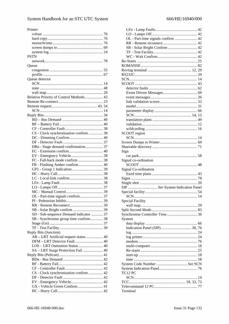
System Handbook for an STC UTC System 666/HE/16940/000
666-HE-16940-000.doc Issue 31 Page 132
Printer colour .............................................................. 76 hard copy......................................................... 76 monochrome.................................................... 76 screen dumps to............................................... 69 system log........................................................ 24
PSTN network............................................................ 78
Queue congestion ....................................................... 55 profile .............................................................. 67
Queue detector SCN................................................................. 14 state ................................................................. 48 wall map .......................................................... 29
Relative Priority of Control Methods................... 43 Remote Re-connect .............................................. 23 Remote request............................................... 43, 54
SCN................................................................. 14 Reply Bits............................................................. 34
BD – Bus Demand .......................................... 40 BF – Battery Fail ............................................. 40 CF - Controller Fault ....................................... 38 CS - Clock synchronisation confirm ............... 38 DC - Dimming Confirm .................................. 40 DF - Detector Fault ......................................... 37 DRn - Stage demand confirmation.................. 37 EC - Extension confirm................................... 40 EV - Emergency Vehicle................................. 38 FC - Fall-back mode confirm.......................... 38 FR - Flashing Amber confirm ......................... 40 GP1 - Group 1 Indication................................ 39 HC - Hurry Call............................................... 38 LC - Local-link confirm .................................. 38 LFn - Lamp Fault ............................................ 38 LO - Lamps Off............................................... 37 MC - Manual Control...................................... 39 OL - Part-time signals confirm........................ 37 PI - Pedestrian Inhibit...................................... 39 RR - Remote Reconnect .................................. 39 SB - Solar Bright confirm ............................... 39 SD - Sub-sequence Demand indicator ............ 37 SR - Synchronise group time confirm............. 38 Stage (Gn) ....................................................... 37 TF - Test Facility............................................. 39
Reply Bits (Junction) AR – LRT Artificial request status ................. 40 DFM – LRT Detector Fault............................. 40 LOS – LRT Outstation Status ......................... 40 SA – LRT Surge Protection Fail ..................... 40
Reply Bits (Pelican) ............................................. 41 BDn - Bus Demand ......................................... 42 BF - Battery Fail.............................................. 42 CF - Controller Fault ....................................... 42 CS - Clock synchronisation confirm ............... 42 DF - Detector Fault ......................................... 42 EV - Emergency Vehicle................................. 42 GX - Vehicle Green Confirm.......................... 41 HC - Hurry Call............................................... 42
LFn - Lamp Faults........................................... 42 LO - Lamps Off............................................... 42 OL - Part-time signals confirm ....................... 42 RR - Remote reconnect ................................... 42 SB - Solar Bright Confirm .............................. 42 TF - Test Facility............................................. 42 WC - Wait Confirm......................................... 42
Re-Starts .............................................................. 25 ROMANSE.......................................................... 82 Roving terminal ............................................. 12, 29 RS232C................................................................ 29 SCN...................................................................... 14 SCOOT ................................................................ 43
detector faults.................................................. 62 Event Driven Messages................................... 69 event messages................................................ 26 link validation screen ...................................... 33 model............................................................... 31 parameter display ............................................ 66 SCN........................................................... 14, 15 translation plans .............................................. 49 validation......................................................... 12 wildcarding ..................................................... 16
SCOOT region SCN................................................................. 14
Screen Dumps to Printer ...................................... 69 Shareable directory .............................................. 71 Sign
car park............................................................ 58 Signal co-ordination
SCOOT ........................................................... 48 Signal Co-ordination
fixed time plans............................................... 43 Signs .................................................................... 78 Single shot ........................................................... 20 SIP .............................. See System Indication Panel Special facility ..................................................... 54
SCN................................................................. 14 Special Facility
wall map.......................................................... 29 Split Second Mode............................................... 83 Synchronise Controller Time............................... 36 System
data display ..................................................... 66 Indication Panel (SIP) ............................... 30, 76 log ................................................................... 24 log printer........................................................ 24 modem............................................................. 76 multi-computer................................................ 18 Re-starts .......................................................... 25 start-up ............................................................ 18 time ................................................................. 18
System Code Number ................................ See SCN System Indication Panel....................................... 76 TC12 PC
SCN................................................................. 14 TCC.......................................................... 18, 33, 73 Telecommand 12 PC............................................ 77 Terminal
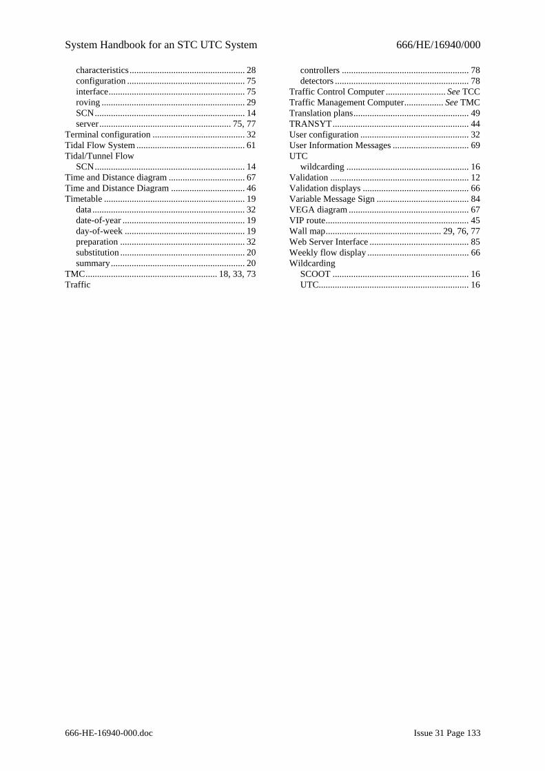
System Handbook for an STC UTC System 666/HE/16940/000
666-HE-16940-000.doc Issue 31 Page 133
characteristics .................................................. 28 configuration ................................................... 75 interface........................................................... 75 roving .............................................................. 29 SCN................................................................. 14 server......................................................... 75, 77
Terminal configuration ........................................ 32 Tidal Flow System ............................................... 61 Tidal/Tunnel Flow
SCN................................................................. 14 Time and Distance diagram ................................. 67 Time and Distance Diagram ................................ 46 Timetable ............................................................. 19
data .................................................................. 32 date-of-year ..................................................... 19 day-of-week .................................................... 19 preparation ...................................................... 32 substitution ...................................................... 20 summary.......................................................... 20
TMC......................................................... 18, 33, 73 Traffic
controllers ....................................................... 78 detectors .......................................................... 78
Traffic Control Computer .......................... See TCC Traffic Management Computer................. See TMC Translation plans.................................................. 49 TRANSYT........................................................... 44 User configuration ............................................... 32 User Information Messages ................................. 69 UTC
wildcarding ..................................................... 16 Validation ............................................................ 12 Validation displays .............................................. 66 Variable Message Sign ........................................ 84 VEGA diagram .................................................... 67 VIP route.............................................................. 45 Wall map.................................................. 29, 76, 77 Web Server Interface ........................................... 85 Weekly flow display ............................................ 66 Wildcarding
SCOOT ........................................................... 16 UTC................................................................. 16