Embed Size (px)
DESCRIPTION
If you are like me you have noticed the badly constructed roads all over Kenya. I thin, if you are gonna build a road you must also make a statement not just a structure in the name of a road. Maybe they should go back to the drawing board & learn design- you know the skill of making stuff look good not just functional. That said, am not a big fan of steel structures especially steel brigdes still I was in the tail end of reading this.
Citation preview
Composite steel highway bridges
Corus Construction & Industrial
ContentsAcknowledgement of author
Advantages of steel bridges
1 Design standards
2 Conceptual design
2.1 Spans and component lengths
2.2 Cross sections
2.3 Intermediate supports
2.4 Bracings
2.5 Steel grades
2.6 Further guidance
3 Initial sizes and overall unit weight
3.1 Introduction
3.2 Use of charts
3.2.1 Plate girder flange sizes
3.2.2 Plate girder web sizes
3.2.3 Overall unit weight
3.2.4 Universal beams
3.2.5 List of symbols
4 Worked examples – use of charts
4.1 Continuous plate girder bridge
4.2 Simply supported universal beam bridge
5 References
6 Figures
Figure 4 – Simply supported bridges
Figure 5 – Continuous bridges – span girders
Figure 6 – Continuous bridges – pier girders
Figure 7 – Girder spacing factors
Figure 8 – Overall unit weights – plate girder bridges
Figure 9 – Universal beams – elastic stress analysis
Figure 10 – Universal beams – plastic stress analysis
2 Composite steel highway bridges
Contents
1. Left: Waterside BridgeNewburgh, Scotland
2. Right: A1(M)Yorkshire, England
This guide is an update of a publication originally
prepared by A.C.G. Hayward. Corus gratefully
acknowledges the work of Mr Hayward and the
contribution made by D.C. Iles, The Steel Construction
Institute, during this update.
Composite steel highway bridges 3
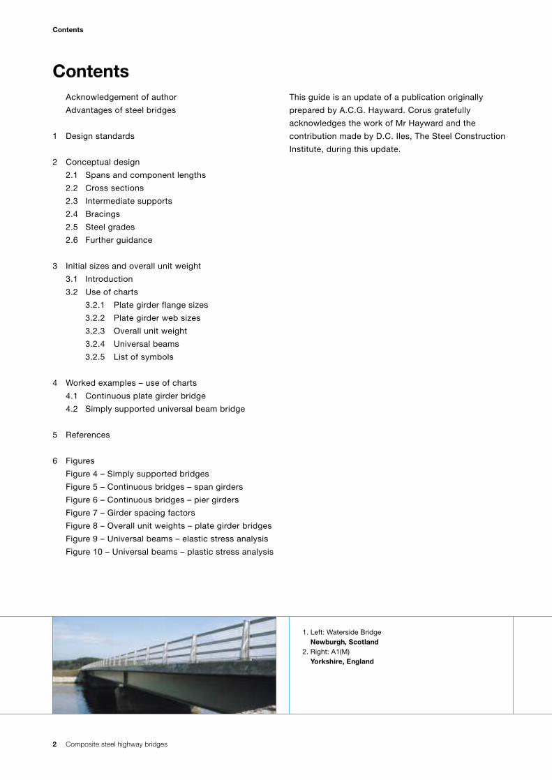
Advantages of steel bridges
The Author
Alan C. G. Hayward FREng CEng FICE FIStructE
Alan Hayward was a founding Partner of bridge
specialists Cass Hayward & Partners of Chepstow who
design and evolve construction methodology for all
types of bridges, particularly steel highway, railway,
footbridges, movable bridges and Roll-On/Roll-Off
linkspans in the UK and overseas. He remains active in
the firm as a Consultant.
Alan Hayward was continuously involved with the
development of bridge codes including BS 5400 and
Eurocodes and has been National Technical Contact for
the composite bridge code EC4-2. He contributes to the
education of engineers by lecturing at Universities on
behalf of industry, and has written numerous papers on
steel bridge construction. He was a long-standing
member of the Steel Bridge Group who disseminate best
practice through their published Guidance Notes.
Advantages of steel bridges Feature Leading to Advantages
Low weight of Fewer piles and smaller sizes of pile caps/foundations. Cheaper foundations.superstructure. Typical 30 – 50% reduction over concrete decks.
Composite bridges 6.0 – 8.0kN/m2 typical.
Light units for erection. Erection by smaller cranes. Delivery of long pieces. Cheaper site costs.Launch erection with light equipment (skates or rollers).
Simple site joints. Bolted joints: easy to form larger pieces from small Flexible site planning.transported components taken to remote sites.
Maximum Quality control in good factory conditions avoiding outdoor More reliable product.pre-fabrication in site affected by weather and difficult access.factory.
Predictable Commuted painting costs can be calculated. If easy repainting Total life cost known.maintenance costs. is made possible by access and good design then no other
maintenance necessary.
Low construction Depth/span ratio 1/20 to 1/30 typically. Slender appearance.depth. Lower depth achieved with half-through girders. Reduces costs of earthworks
in approaches.
Self supporting Falsework eliminated. Falsework costs eliminated.during construction. Slab formwork and falsework also avoided using permanent formwork. Significant if more than 8m
above ground.
Continuous and Continuity easy with bolted or welded joints. Most expansion Better appearance.integral spans. joints eliminated. Number of bearings reduced. Improved durability.
Compliance with BD57. Improved running surface.
Adaptable details. Pleasing appearance taking advantage of curves and colour. Aesthetic gain.
Re-usable product. Demountable structures and recyclable components which Sustainable product.reduce manufacturing energy input.
Composite steel highway bridges
4 Composite steel highway bridges
The current bridge code BS 5400 (Ref. 1) was conceived
in 1967. Its ten parts cover the more common structural
media. The 1980 conference in Cardiff introduced the
Code relating to steel and made use of research carried
out since 1970.
Part 3 (Design of Steel Bridges) is compatible with the
workmanship standards and tolerances defined in Part
6, drawn up jointly with industry.
The Code uses limit state principles. The ultimate
limit state (ULS) and serviceability limit state (SLS) must
be satisfied.
In practice the ULS generally governs, exceptions being
the checking at SLS for slip of HSFG bolts and the
design of shear connectors.
BS 5400 encourages the use of steel for a number
of reasons:
(i) Plastic stress analysis option offers the use of
lighter members and extends the span range of
rolled sections.
(ii) Design clauses are easier to use than
previous Codes.
(iii) Workmanship requirements, including tolerances,
are rationalised.
(iv) Longitudinal web stiffeners to girders are
rarely needed.
Use of the plastic modulus is permitted for stress
analysis of compact sections and where the slenderness
is controlled by sufficient restraints, the effects of
shrinkage and differential temperature can be neglected.
For ‘compact’ sections, the entire load can also be
assumed to act on the composite section even if the
steelwork is unpropped, provided that SLS checks
are made.
While most rolled universal beams, columns and
channels will be compact, plate girders will often be
non-compact and must be stressed elastically. (See also
Section 3.2.4.)
For structural analysis, elastic methods are utilised
using gross sections (i.e. not allowing for shear lag or
effective width).
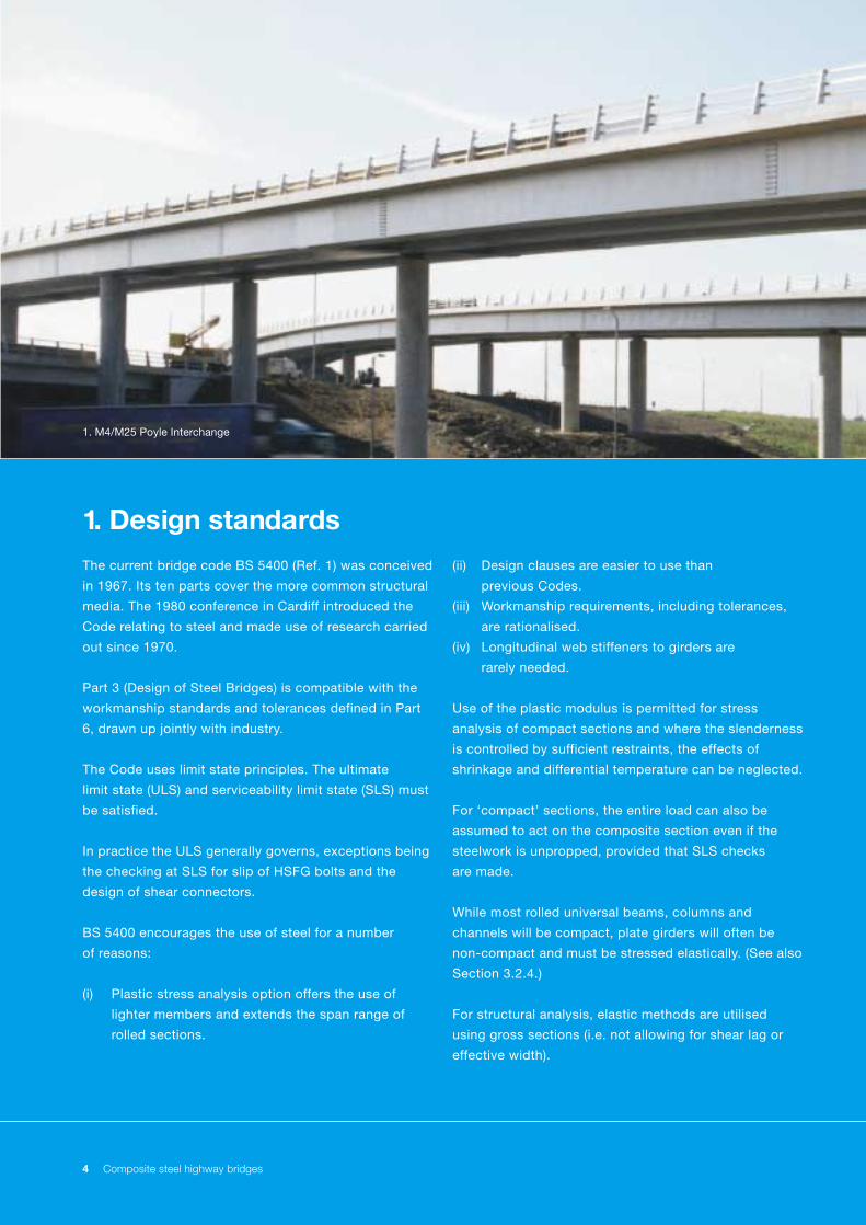
1. M4/M25 Poyle Interchange
1. Design standards
Composite steel highway bridges 5
Redistribution of moments arising from the formation of
plastic hinges is not permitted, but redistribution due to
cracking of concrete over intermediate supports may be
assumed using Part 5.
Combined bending and shear is dealt with using
interaction formulae. This is sometimes critical at
intermediate supports.
The Code contains no specific limits on slenderness of
members or proportion of plate panels. Longitudinal web
stiffeners are usually only necessary for very deep
girders or those with curved soffits.
For rolled sections the full shear yield stress can
generally be used without the need for intermediate
stiffeners. Bearing stiffeners are virtually mandatory at
supports, together with lateral bracing or a system of
bracing to maintain verticality.
Fatigue is checked to Part 10, although for highway
bridges this rarely demands a reduction in working
stresses provided good detailing practice is used.
For example:
(i) Do not locate welded attachments close to or on
flange edges (class 'G').
(ii) Re-entrant corners should be radiused.
(iii) Use HSFG bolts for permanent bolted connections.
(iv) Restrict doubler flange ends to areas of low stress
(class 'G').
(v) Avoid single sided partial penetration butt welded
joints which are subject to tensile stress.
(vi) Avoid welded cruciform joints, which are subject to
significant tensile stresses. An example is when
using integral crossheads (see Figs. 1B & 1F)
where fillet welds should be used in preference to
full penetration butt welds. If butt welds are
necessary, the use of steel with through-thickness
quality (Z-grades to BS EN 10164 – Ref 14) may be
considered in view of the strains which will be
caused during welding.
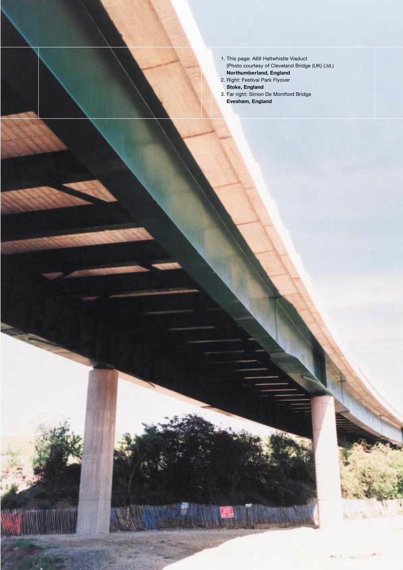
1. This page: A69 Haltwhistle Viaduct(Photo courtesy of Cleveland Bridge (UK) Ltd.)Northumberland, England
2. Right: Festival Park FlyoverStoke, England
3. Far right: Simon De Montford BridgeEvesham, England
Composite steel highway bridges 7
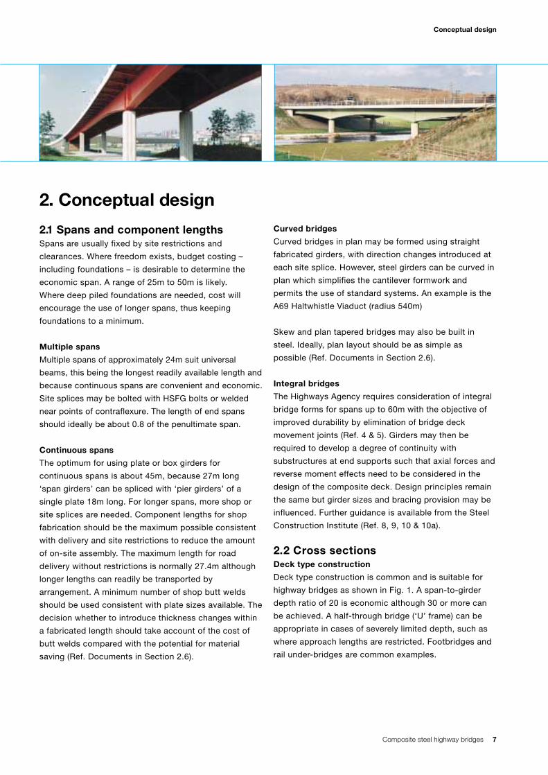
Conceptual design
2.1 Spans and component lengthsSpans are usually fixed by site restrictions and
clearances. Where freedom exists, budget costing –
including foundations – is desirable to determine the
economic span. A range of 25m to 50m is likely.
Where deep piled foundations are needed, cost will
encourage the use of longer spans, thus keeping
foundations to a minimum.
Multiple spans
Multiple spans of approximately 24m suit universal
beams, this being the longest readily available length and
because continuous spans are convenient and economic.
Site splices may be bolted with HSFG bolts or welded
near points of contraflexure. The length of end spans
should ideally be about 0.8 of the penultimate span.
Continuous spans
The optimum for using plate or box girders for
continuous spans is about 45m, because 27m long
‘span girders’ can be spliced with ‘pier girders’ of a
single plate 18m long. For longer spans, more shop or
site splices are needed. Component lengths for shop
fabrication should be the maximum possible consistent
with delivery and site restrictions to reduce the amount
of on-site assembly. The maximum length for road
delivery without restrictions is normally 27.4m although
longer lengths can readily be transported by
arrangement. A minimum number of shop butt welds
should be used consistent with plate sizes available. The
decision whether to introduce thickness changes within
a fabricated length should take account of the cost of
butt welds compared with the potential for material
saving (Ref. Documents in Section 2.6).
Curved bridges
Curved bridges in plan may be formed using straight
fabricated girders, with direction changes introduced at
each site splice. However, steel girders can be curved in
plan which simplifies the cantilever formwork and
permits the use of standard systems. An example is the
A69 Haltwhistle Viaduct (radius 540m)
Skew and plan tapered bridges may also be built in
steel. Ideally, plan layout should be as simple as
possible (Ref. Documents in Section 2.6).
Integral bridges
The Highways Agency requires consideration of integral
bridge forms for spans up to 60m with the objective of
improved durability by elimination of bridge deck
movement joints (Ref. 4 & 5). Girders may then be
required to develop a degree of continuity with
substructures at end supports such that axial forces and
reverse moment effects need to be considered in the
design of the composite deck. Design principles remain
the same but girder sizes and bracing provision may be
influenced. Further guidance is available from the Steel
Construction Institute (Ref. 8, 9, 10 & 10a).
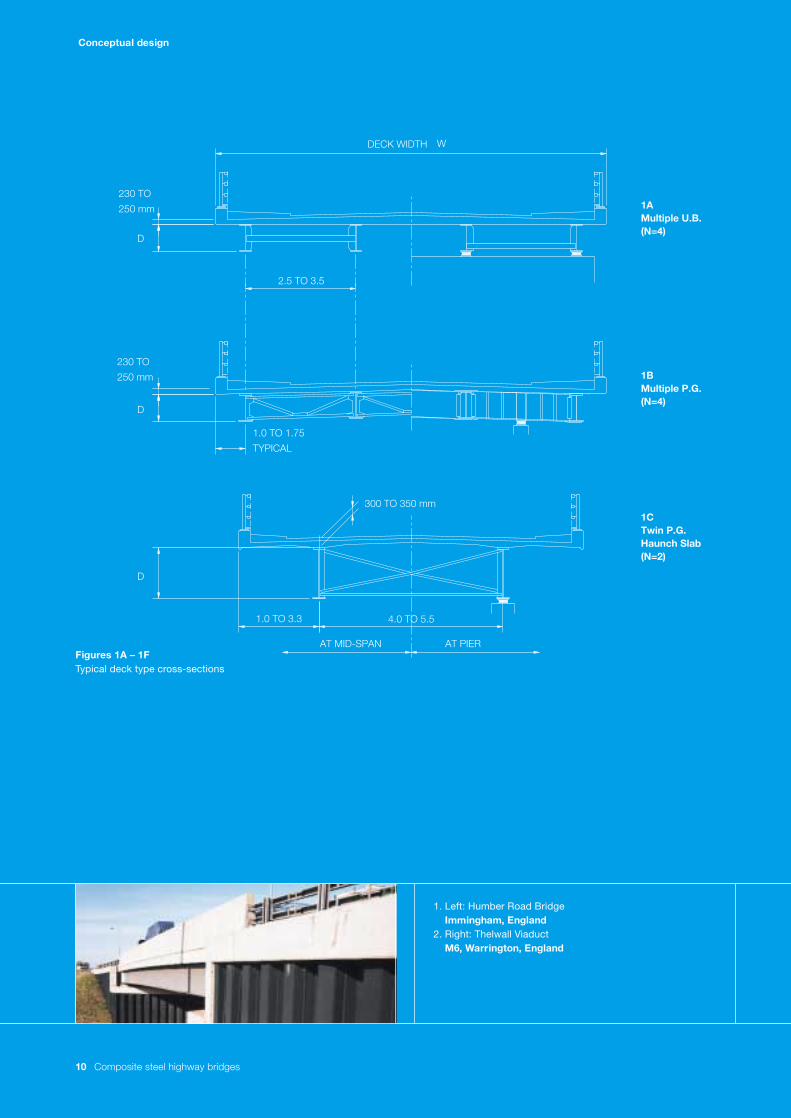
2.2 Cross sections Deck type construction
Deck type construction is common and is suitable for
highway bridges as shown in Fig. 1. A span-to-girder
depth ratio of 20 is economic although 30 or more can
be achieved. A half-through bridge (‘U’ frame) can be
appropriate in cases of severely limited depth, such as
where approach lengths are restricted. Footbridges and
rail under-bridges are common examples.
2. Conceptual design
8 Composite steel highway bridges
Conceptual design
Where permanent formwork is envisaged, the slab
should be made sufficiently thick to accommodate the
details taking account of reinforcement cover and
practical tolerances (Ref. 7). When using composite part
depth planks such as Omnia then a minimum thickness
of 250mm may be needed.
Universal beams and plate girders
Universal beams may be appropriate for bridges up to
25m span and above when continuous, or when use can
be made of the plastic modulus. For spans above 22m,
plate girders, especially if continuous, can be economic
because lighter sections can be inserted in mid-span
regions. Costs per tonne of painted and erected
universal beams were traditionally lower but, more
recently, automated fabrication and less expensive plate
material has allowed economic supply of plate girders
for the shorter spans.
A girder spacing of 3.0m to 3.5m is usual with a deck
slab of about 250mm thick (see Figs. 1A and 1B). Edge
cantilevers should not exceed half the beam spacing
and to simplify falsework should, where possible be less
than 1.5m. Shorter cantilevers are usually necessary
with a locally thickened slab where very high
containment parapets are specified, e.g. over rail tracks.
An even number of girders achieves better optimisation
of material (ordering) and allows bracing in pairs. For
wide girder spacings, the slab may be haunched, but
use of standardised permanent formwork is unlikely to
be possible and construction depth is increased (see
Fig. 1C). Where spans exceed 40m, twin plate girders
with a central stringer have been used on some single
carriageway decks up to about 13m wide (see Fig. 1D).
Twin girders and cross beams (often referred to as
ladder decks) have proved economic for a wide range of
spans (Ref. 10b). They can be used for single
carriageway decks (see Fig. 1E) and for wider decks
supporting more lanes.
Box girders
Where spans exceed 100m box girders are likely to be
more economic than plate girders with which flange sizes
would be excessive. Other reasons for using box girders
include aesthetics (where justifiable), aerodynamic
stability, severe plan curvature, the need for single column
supports or very limited depth. Other than in the cases
noted, box girders – being heavier than plate girders – are
more expensive because although less flange material
may be demanded due to inherent torsional properties,
this is usually more than offset by the amount of internal
stiffening and extra costs for workmanship. Fabrication
costs are higher because the assembly/welding
processes take longer and more shop space is needed.
However, erection work is often reduced because box
girders require little or no external bracing.
Multiple box girders have in the past proved to be
economic for spans of around 50m in particular
situations. Using narrow cross sections eliminates the
need for longitudinal stiffeners (see Fig. 1F). An example
of which is the M25/M4 Poyle Interchange.
For box girders, consideration of the safety of personnel in
confined spaces is essential during fabrication, erection and
for maintenance. Detailing must recognise the need to avoid
internal welding as far as possible and to allow sufficient
ventilation and openings for access and recovery in
emergency situations.
Open-topped trapezoidal and rectangular shaped box
girders have been used efficiently, but provisions are
needed to preserve stability during erection, for example the
Forrest Way Bridge, Warrington.
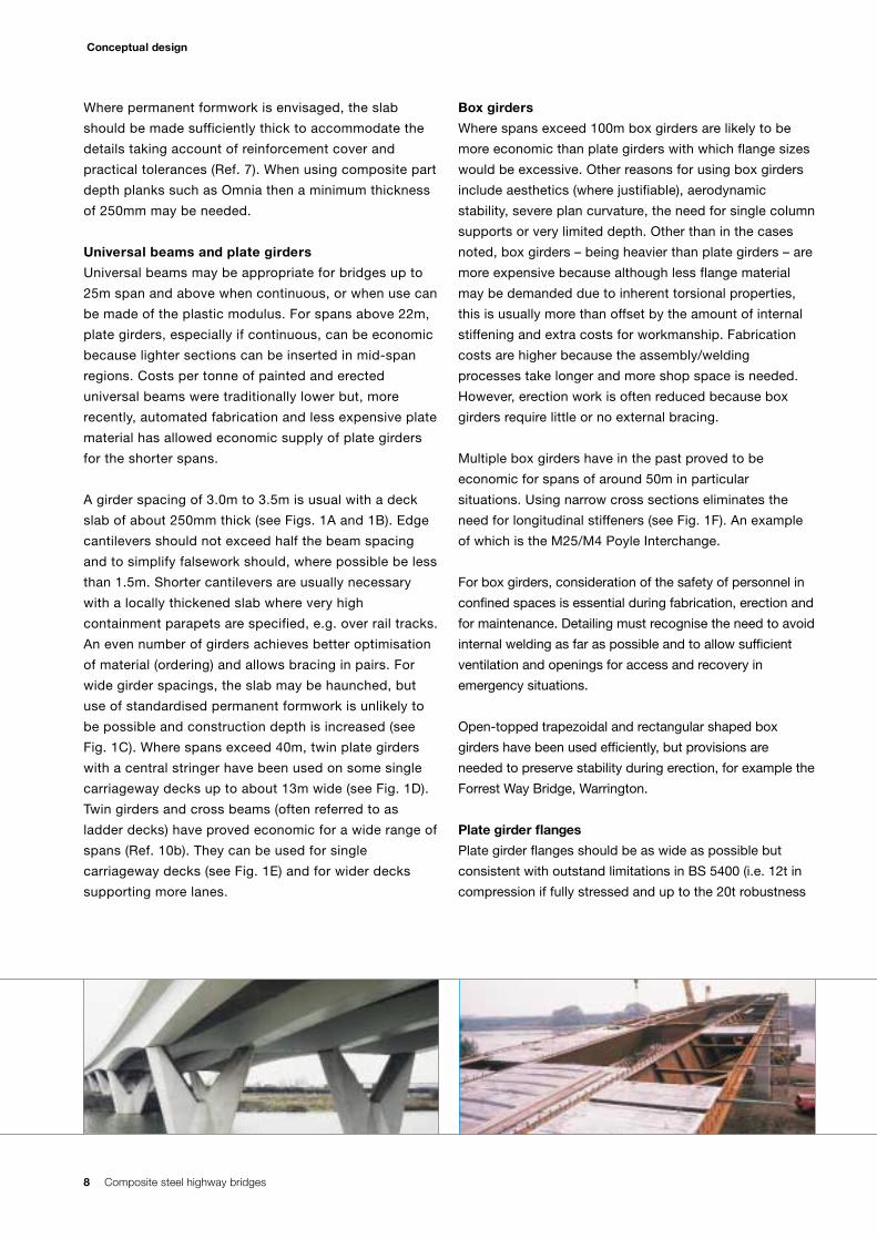
Plate girder flanges
Plate girder flanges should be as wide as possible but
consistent with outstand limitations in BS 5400 (i.e. 12t in
compression if fully stressed and up to the 20t robustness
Composite steel highway bridges 9
Conceptual design
1. Far Left: Nene BridgePeterborough, England
2. Left: Forrest Way BridgeWarrington, England
3. Right: M20 Road BridgeFolkstone, England
limit), to give the best achievable stability during erection
and to reduce the number of bracings. For practical
reasons a desirable minimum width is about 400mm to
accommodate detailing for certain types of permanent
formwork, especially precast concrete. A maximum flange
thickness of 63mm is recommended to avoid heavy welds,
minimise pre-heating requirements and also limit the
reduction in design yield strength. Limiting the thickness
also has benefits in terms of notch toughness specification.
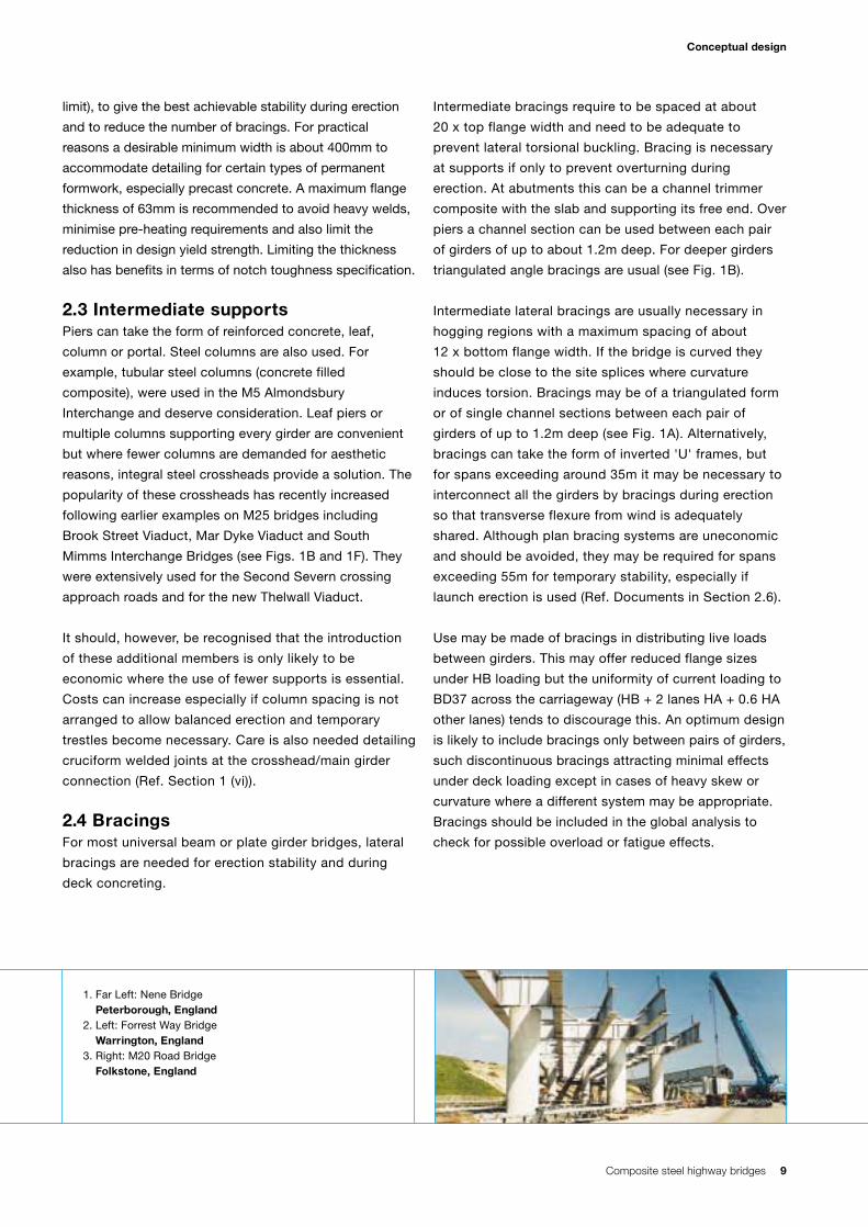
2.3 Intermediate supports Piers can take the form of reinforced concrete, leaf,
column or portal. Steel columns are also used. For
example, tubular steel columns (concrete filled
composite), were used in the M5 Almondsbury
Interchange and deserve consideration. Leaf piers or
multiple columns supporting every girder are convenient
but where fewer columns are demanded for aesthetic
reasons, integral steel crossheads provide a solution. The
popularity of these crossheads has recently increased
following earlier examples on M25 bridges including
Brook Street Viaduct, Mar Dyke Viaduct and South
Mimms Interchange Bridges (see Figs. 1B and 1F). They
were extensively used for the Second Severn crossing
approach roads and for the new Thelwall Viaduct.
It should, however, be recognised that the introduction
of these additional members is only likely to be
economic where the use of fewer supports is essential.
Costs can increase especially if column spacing is not
arranged to allow balanced erection and temporary
trestles become necessary. Care is also needed detailing
cruciform welded joints at the crosshead/main girder
connection (Ref. Section 1 (vi)).
2.4 Bracings For most universal beam or plate girder bridges, lateral
bracings are needed for erection stability and during
deck concreting.
Intermediate bracings require to be spaced at about
20 x top flange width and need to be adequate to
prevent lateral torsional buckling. Bracing is necessary
at supports if only to prevent overturning during
erection. At abutments this can be a channel trimmer
composite with the slab and supporting its free end. Over
piers a channel section can be used between each pair
of girders of up to about 1.2m deep. For deeper girders
triangulated angle bracings are usual (see Fig. 1B).
Intermediate lateral bracings are usually necessary in
hogging regions with a maximum spacing of about
12 x bottom flange width. If the bridge is curved they
should be close to the site splices where curvature
induces torsion. Bracings may be of a triangulated form
or of single channel sections between each pair of
girders of up to 1.2m deep (see Fig. 1A). Alternatively,
bracings can take the form of inverted 'U' frames, but
for spans exceeding around 35m it may be necessary to
interconnect all the girders by bracings during erection
so that transverse flexure from wind is adequately
shared. Although plan bracing systems are uneconomic
and should be avoided, they may be required for spans
exceeding 55m for temporary stability, especially if
launch erection is used (Ref. Documents in Section 2.6).
Use may be made of bracings in distributing live loads
between girders. This may offer reduced flange sizes
under HB loading but the uniformity of current loading to
BD37 across the carriageway (HB + 2 lanes HA + 0.6 HA
other lanes) tends to discourage this. An optimum design
is likely to include bracings only between pairs of girders,
such discontinuous bracings attracting minimal effects
under deck loading except in cases of heavy skew or
curvature where a different system may be appropriate.
Bracings should be included in the global analysis to
check for possible overload or fatigue effects.
10 Composite steel highway bridges
Conceptual design
1. Left: Humber Road BridgeImmingham, England
2. Right: Thelwall Viaduct M6, Warrington, England
DECK WIDTH
230 TO
250 mm
2.5 TO 3.5
1.0 TO 1.75
TYPICAL
300 TO 350 mm
1.0 TO 3.3 4.0 TO 5.5
W
230 TO
250 mm
D
D
D
1BMultiple P.G.(N=4)
1CTwin P.G.Haunch Slab(N=2)
1AMultiple U.B.(N=4)
AT MID-SPAN AT PIERFigures 1A – 1FTypical deck type cross-sections
Composite steel highway bridges 11
Conceptual design
230 TO 320 mm
6.0 TO 7.0
3.0 TO 3.5 c/c
0.9 TO 1.2 2.5 TO 3.5
AT MID-SPAN AT PIER
1.0 TO 3.3
>7.0
230 TO
250 mm
230 TO
250 mm
D
D
D
1DTwin P.G.& Stringer(N=2)
1ETwin P.G.& Cross Girders(N=2)
1FMultiple Box(N=6)
12 Composite steel highway bridges
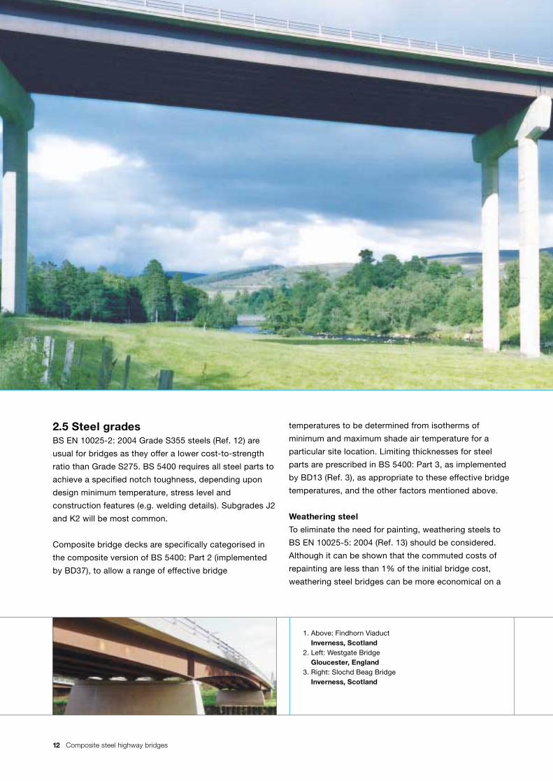
2.5 Steel gradesBS EN 10025-2: 2004 Grade S355 steels (Ref. 12) are
usual for bridges as they offer a lower cost-to-strength
ratio than Grade S275. BS 5400 requires all steel parts to
achieve a specified notch toughness, depending upon
design minimum temperature, stress level and
construction features (e.g. welding details). Subgrades J2
and K2 will be most common.
Composite bridge decks are specifically categorised in
the composite version of BS 5400: Part 2 (implemented
by BD37), to allow a range of effective bridge
temperatures to be determined from isotherms of
minimum and maximum shade air temperature for a
particular site location. Limiting thicknesses for steel
parts are prescribed in BS 5400: Part 3, as implemented
by BD13 (Ref. 3), as appropriate to these effective bridge
temperatures, and the other factors mentioned above.
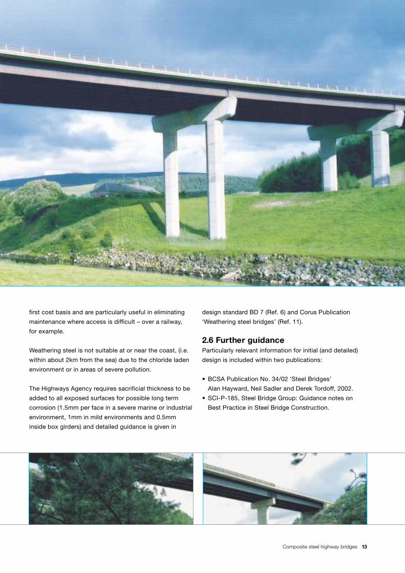
Weathering steel
To eliminate the need for painting, weathering steels to
BS EN 10025-5: 2004 (Ref. 13) should be considered.
Although it can be shown that the commuted costs of
repainting are less than 1% of the initial bridge cost,
weathering steel bridges can be more economical on a
1. Above: Findhorn ViaductInverness, Scotland
2. Left: Westgate BridgeGloucester, England
3. Right: Slochd Beag BridgeInverness, Scotland
Composite steel highway bridges 13
first cost basis and are particularly useful in eliminating
maintenance where access is difficult – over a railway,
for example.
Weathering steel is not suitable at or near the coast, (i.e.
within about 2km from the sea) due to the chloride laden
environment or in areas of severe pollution.
The Highways Agency requires sacrificial thickness to be
added to all exposed surfaces for possible long term
corrosion (1.5mm per face in a severe marine or industrial
environment, 1mm in mild environments and 0.5mm
inside box girders) and detailed guidance is given in
design standard BD 7 (Ref. 6) and Corus Publication
‘Weathering steel bridges’ (Ref. 11).
2.6 Further guidanceParticularly relevant information for initial (and detailed)
design is included within two publications:
• BCSA Publication No. 34/02 ‘Steel Bridges’
Alan Hayward, Neil Sadler and Derek Tordoff, 2002.
• SCI-P-185, Steel Bridge Group: Guidance notes on
Best Practice in Steel Bridge Construction.
14 Composite steel highway bridges
Initial sizes and overall unit weight
3. Initial sizes and overallunit weight 3.1 IntroductionCharts are given to provide initial estimates of flange
area (Af) web thickness (tw) and overall unit weight of
steelwork (kg/m2) for typical composite bridge cross
sections as shown in Fig. 1.
Continuous or simply supported span plate girders and
simply supported universal beams are included. The
charts were derived from approximate BS 5400 designs
using simplifying assumptions for loads, transverse
distribution and to achieve correlation with modern
bridges. The charts take account of the latest highway
loading requirements in BD37.
It is emphasised that the sizes obtained do not represent
final designs, which must always be executed to take
account of all factors, such as bridge configuration and
loading. Adjustments will need to be made to take
account of the likely effects of end continuity if integral
construction is intended.
The charts are based on the following assumptions:
(i) Deck slab 250mm average thickness (6.25kN/m2).
(ii) Superimposed dead loads equivalent to 100mm of
surfacing (2.40 kN/m2).
(iii) Permanent formwork weight 0.50 kN/m2 of slab
soffit area.
(iv) Steel grade S355.
(v) Span to depth ratios L/D of 20 & 30.
(vi) Plate girder webs have vertical stiffeners at approx.
2.0m centres where such stiffening is required.
(vii) Elastic stress analysis is used for plate girders. If
however the plastic modulus is used for compact
cross sections, then economies may be possible.
(viii) Steelwork is unpropped and therefore not acting
compositely under its own weight and that of the
concrete slab. The steel is however composite for
all superimposed loads after the concrete has cured.
(ix) Sufficient transverse bracings are included such
that bending stresses are not significantly reduced
due to buckling criteria.
(x) Top flanges in sagging regions are dictated by the
maximum stress during concreting allowing for
formwork and live load – to BS 5975 (Ref. 15).
Continuous bridge mid-span regions are concreted
in turn followed by portions over the piers.
(xi) Live loading HA (assuming 3.5m wide lanes), or
alternatively 45 units of HB loading with co-existent
HA loading (BD37).
(xii) Continuous spans are approximately equal.
3.2 Use of charts
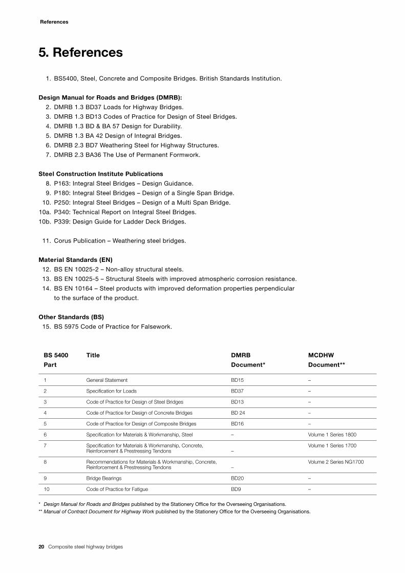
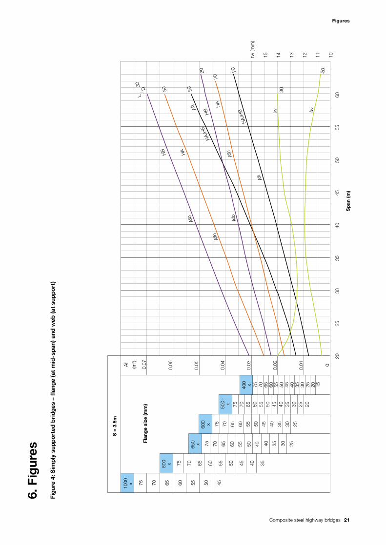
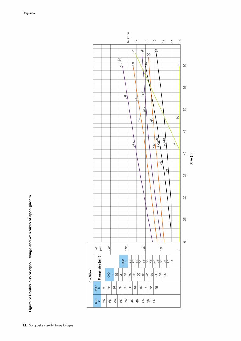
3.2.1 Plate girder flange sizesFlange areas (Af in m2) are read against the span L.
(a) For simply supported bridges – (refer Fig. 4)
(b) For continuous bridges –
Size of span girder (refer Fig. 5)
Size of pier girder (refer Fig. 6)
Figures 4, 5 and 6 are applicable to an average girder
spacing ‘s’ of 3.5m. Fig. 7 gives a girder spacing factor
Kaf which is multiplied by the flange areas, obtained
above, to give values appropriate to the actual average
girder spacing.
i.e. Top Flange Aft = Aft (Figs. 4, 5 or 6) x Kaf (Fig. 7)
i.e. Bottom Flange Afb = Afb (Figs. 4, 5 or 6) x Kaf ( Fig. 7)
Two different span-to-depth ratios, L/D = 20 and L/D =
30, are included for either HB or alternatively HA loading.
Values for intermediate L/D ratios can be read
by interpolation.
Composite steel highway bridges 15
Initial sizes and overall unit weight
The charts also show actual flange sizes using
400mm x 15mm to 1000mm x 75mm.
Flange area of pier girders of continuous unequal spans
can be estimated by taking the greater of the two
adjacent spans.
End spans of continuous bridges may be estimated
using L = 1.25 x actual span.
3.2.2 Plate girder web sizes Web thicknesses are similarly obtained using Figs. 4, 5
and 6 applicable to 's' = 3.5m. Adjustment for the actual
average girder spacing 's' is obtainable from Fig. 7 using
girder spacing factor ktw.
i.e. Web thickness tw = tw (Figs. 4, 5 or 6) x ktw (Fig. 7).
The thickness obtained may be regarded as reasonably
typical. However, designers may prefer to opt for thicker
webs to reduce the number of web stiffeners.
3.2.3 Overall unit weight Overall unit weight (kg/m2 of gross deck area) for plate
girders is read against the span L from Fig. 8 for simply
supported or continuous bridges with L/D ratios of 20 or
30, under HB or alternatively HA loading and applicable
to ‘s’ = 3.5m.
Adjustment for average girder spacing 's' other than
3.5m is obtainable from Fig. 7 using girder spacing
factor kw.
i.e. Unit weight kg/m2 = kg/m2 (Fig. 8) x kw (Fig. 7).
The unit weight provides an approximate first
estimate of steelwork tonnage allowing for all stiffeners
and bracings.
For continuous bridges with variable depth, Fig. 8 may
be used to provide a rough guide, assuming a span-to-
depth (L/D) ratio for each span based upon the average
girder depth (D) within that span.
For box girder bridges a rough estimate may be
obtained assuming that N = 2 x number of box girders in
the cross section (see Fig. 1F where N = 2 x 3 = 6).
For continuous bridges the end spans should be assumed
as 1.25 x actual span, following which the mean span for
use in Fig. 8 may be determined as follows:
Mean span L = L14 + L2
4...Ln4
n
where n = number of spans.
3.2.4 Universal beams An indication of beam size for simply supported spans
may be obtained from Figs. 9 and 10 for elastic or
plastic stress analysis respectively. BS 5400 permits the
use of either option, provided that the cross section is
‘compact’; this condition being satisfied for all sections
shown in Fig. 10. Sufficient ductility is also required. It is
apparent that plastic stress analysis can achieve
significant economy in extending the span range of
universal beams. In practice, a serviceability stress
check (SLS) must be made including the effects of shear
lag. There is advantage also in using the plastic design
option for continuous spans but some universal beams
may need to be classed as 'non-compact', requiring
elastic analysis in hogging regions because the web
depth between the (elastic) neutral axis and its
compressive edge may exceed 28tw, depending upon
the amount of longitudinal slab reinforcement.
An overall unit weight for universal beam bridges may be
estimated at the conceptual stage by adding an
allowance of approximately 8% to the weight of the
main beams to allow for any bracings and stiffeners etc.
Figs. 9 and 10 refer to mass per metre of universal beams.
4
1. Left: Milton BridgeLesmahagow, Scotland
2. Right: Fossdyke Bridge(Photo courtesy of Cleveland Bridge (UK) Ltd.)Lincoln, England
16 Composite steel highway bridges
Initial sizes and overall unit weight
Reference Universal beam size Actual depth (mm)figures 9 & 10
Serial Mass per size (mm) metre (kg/m)
388 914 x 419 388 921.0
343 343 911.8
289 914 x 305 289 926.6
253 253 918.4
224 224 910.4
201 201 903.0
226 838 x 292 226 850.9
194 194 840.7
176 176 834.9
197 762 x 267 197 769.8
173 173 762.2
147 147 754.0
170 686 x 254 170 692.9
152 152 687.5
140 140 683.5
125 125 677.9
238 610 x 305 238 635.8
179 179 620.2
149 149 612.4
140 610 x 229 140 617.2
125 125 612.2
113 113 607.6
101 101 602.6
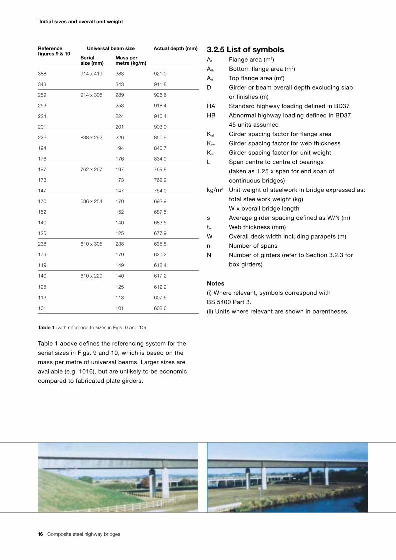
Table 1 (with reference to sizes in Figs. 9 and 10)
Table 1 above defines the referencing system for the
serial sizes in Figs. 9 and 10, which is based on the
mass per metre of universal beams. Larger sizes are
available (e.g. 1016), but are unlikely to be economic
compared to fabricated plate girders.
3.2.5 List of symbolsAf Flange area (m2)
Afb Bottom flange area (m2)
Aft Top flange area (m2)
D Girder or beam overall depth excluding slab
or finishes (m)
HA Standard highway loading defined in BD37
HB Abnormal highway loading defined in BD37,
45 units assumed
Kaf Girder spacing factor for flange area
Ktw Girder spacing factor for web thickness
Kw Girder spacing factor for unit weight
L Span centre to centre of bearings
(taken as 1.25 x span for end span of
continuous bridges)
kg/m2 Unit weight of steelwork in bridge expressed as:
total steelwork weight (kg)
W x overall bridge length
s Average girder spacing defined as W/N (m)
tw Web thickness (mm)
W Overall deck width including parapets (m)
n Number of spans
N Number of girders (refer to Section 3.2.3 for
box girders)
Notes
(i) Where relevant, symbols correspond with
BS 5400 Part 3.
(ii) Units where relevant are shown in parentheses.
Composite steel highway bridges 17
Worked examples – use of charts
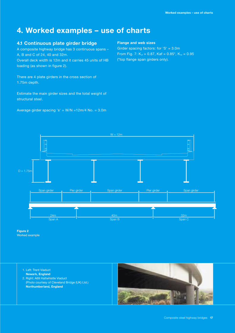
4.1 Continuous plate girder bridge A composite highway bridge has 3 continuous spans –
A, B and C of 24, 40 and 32m.
Overall deck width is 12m and it carries 45 units of HB
loading (as shown in figure 2).
There are 4 plate girders in the cross section of
1.75m depth.
Estimate the main girder sizes and the total weight of
structural steel.
Average girder spacing 's' = W/N =12m/4 No. = 3.0m
Figure 2 Worked example
Flange and web sizes
Girder spacing factors: for 'S' = 3.0m
From Fig. 7: Kaf = 0.87, Kaf = 0.85*, Ktw = 0.95
(*top flange span girders only).
Span girder Pier girderPier girder Span girderSpan girder
W = 12m
24m 40m 32mSpan A Span B Span C
D = 1.75m
1. Left: Trent ViaductNewark, England
2. Right: A69 Haltwhistle Viaduct(Photo courtesy of Cleveland Bridge (UK) Ltd.)Northumberland, England
4. Worked examples – use of charts
18 Composite steel highway bridges
Worked examples – use of charts
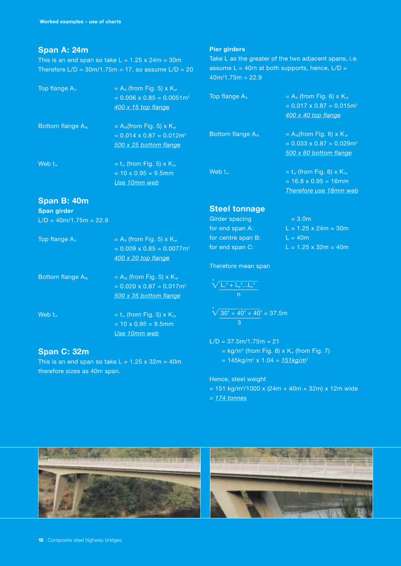
Span A: 24m This is an end span so take L = 1.25 x 24m = 30m
Therefore L/D = 30m/1.75m = 17, so assume L/D = 20
Top flange Aft = Aft (from Fig. 5) x Kaf
= 0.006 x 0.85 = 0.0051m2
400 x 15 top flange
Bottom flange Afb = Afb(from Fig. 5) x Kaf
= 0.014 x 0.87 = 0.012m2
500 x 25 bottom flange
Web tw = tw (from Fig. 5) x Ktw
= 10 x 0.95 = 9.5mm
Use 10mm web
Span B: 40m Span girder
L/D = 40m/1.75m = 22.9
Top flange Aft = Aft (from Fig. 5) x Kaf
= 0.009 x 0.85 = 0.0077m2
400 x 20 top flange
Bottom flange Afb = Afb (from Fig. 5) x Kaf
= 0.020 x 0.87 = 0.017m2
500 x 35 bottom flange
Web tw = tw (from Fig. 5) x Ktw
= 10 x 0.95 = 9.5mm
Use 10mm web
Span C: 32m This is an end span so take L = 1.25 x 32m = 40m
therefore sizes as 40m span.
Pier girders
Take L as the greater of the two adjacent spans, i.e.
assume L = 40m at both supports, hence, L/D =
40m/1.75m = 22.9
Top flange Aft = Aft (from Fig. 6) x Kaf
= 0.017 x 0.87 = 0.015m2
400 x 40 top flange
Bottom flange Afb = Afb(from Fig. 6) x K af
= 0.033 x 0.87 = 0.029m2
500 x 60 bottom flange
Web tw = tw (from Fig. 6) x Ktw
= 16.8 x 0.95 = 16mm
Therefore use 18mm web
Steel tonnage Girder spacing = 3.0m
for end span A: L = 1.25 x 24m = 30m
for centre span B: L = 40m
for end span C: L = 1.25 x 32m = 40m
Therefore mean span
4
L14 + L2
4...Ln4
n
4
304 + 404 + 404 = 37.5m
3
L/D = 37.5m/1.75m = 21
= kg/m2 (from Fig. 8) x Kw (from Fig. 7)
= 145kg/m2 x 1.04 = 151kg/m2
Hence, steel weight
= 151 kg/m2/1000 x (24m + 40m + 32m) x 12m wide
= 174 tonnes
Composite steel highway bridges 19
Worked examples – use of charts
4.2 Simply supported universal beam bridgeA composite bridge has a simply supported span of
24m. (as shown in figure 3). Overall deck width is 9.6m
and it carries HA loading only. Estimate the beam size
and total weight of structural steel assuming there are 4
beams in the cross section.
Figure 3 Worked example
(a) For an elastic stress analysis refer to Fig. 9
For 4 beams
'S' = 9.6m/4No. = 2.4m. Use 388
i.e. 914 x 419 x 388kg/m Universal Beam
Total weight approx.
(388kg/m/1000) x 4No. x 24m x 1.08
(the 1.08 factor allows for 8% bracing + stiffener
allowance)
= 40.2 tonnes (i.e. 174kg/m )
(b) For a plastic stress analysis refer to Fig. 10
For 'S' = 2.4m. Use 289
i.e. 914 x 305 x 289kg/m universal beam
Total weight approx.
(289kg/m /1000) x 4No. x 24m x 1.08
= 30 tonnes (i.e. 130kg/m )
Thus, plastic stress analysis offers a significant
reduction in beam size but SLS checks must be made.
W = 9.6m
24m
2
2
1. Left: A9 BridgePitlochry, Scotland
2. Right: A1(M)Yorkshire, England
20 Composite steel highway bridges
References
5. References
1. BS5400, Steel, Concrete and Composite Bridges. British Standards Institution.
Design Manual for Roads and Bridges (DMRB):
2. DMRB 1.3 BD37 Loads for Highway Bridges.
3. DMRB 1.3 BD13 Codes of Practice for Design of Steel Bridges.
4. DMRB 1.3 BD & BA 57 Design for Durability.
5. DMRB 1.3 BA 42 Design of Integral Bridges.
6. DMRB 2.3 BD7 Weathering Steel for Highway Structures.
7. DMRB 2.3 BA36 The Use of Permanent Formwork.
Steel Construction Institute Publications
8. P163: Integral Steel Bridges – Design Guidance.
9. P180: Integral Steel Bridges – Design of a Single Span Bridge.
10. P250: Integral Steel Bridges – Design of a Multi Span Bridge.
10a. P340: Technical Report on Integral Steel Bridges.
10b. P339: Design Guide for Ladder Deck Bridges.
11. Corus Publication – Weathering steel bridges.
Material Standards (EN)
12. BS EN 10025-2 – Non-alloy structural steels.
13. BS EN 10025-5 – Structural Steels with improved atmospheric corrosion resistance.
14. BS EN 10164 – Steel products with improved deformation properties perpendicular
to the surface of the product.
Other Standards (BS)
15. BS 5975 Code of Practice for Falsework.
BS 5400 Title DMRB MCDHW
Part Document* Document**
1 General Statement BD15 –
2 Specification for Loads BD37 –
3 Code of Practice for Design of Steel Bridges BD13 –
4 Code of Practice for Design of Concrete Bridges BD 24 –
5 Code of Practice for Design of Composite Bridges BD16 –
6 Specification for Materials & Workmanship, Steel – Volume 1 Series 1800
7 Specification for Materials & Workmanship, Concrete, Volume 1 Series 1700Reinforcement & Prestressing Tendons –
8 Recommendations for Materials & Workmanship, Concrete, Volume 2 Series NG1700Reinforcement & Prestressing Tendons –
9 Bridge Bearings BD20 –
10 Code of Practice for Fatigue BD9 –
* Design Manual for Roads and Bridges published by the Stationery Office for the Overseeing Organisations.** Manual of Contract Document for Highway Work published by the Stationery Office for the Overseeing Organisations.
Composite steel highway bridges 21
Figures
20
75 70 65 60 55 50 45
75 70 65 60 55 50 45 40 35
S =
3.5
m
0.07
0.06
0.05
0.04
0.03
0.02
0.01 0
2025
3035
4045
5055
60101112131415tw
(mm
)
Sp
an (m
)
1000 x
800
x
650
x60
0 x
500
x
400
x
Flan
ge
size
(mm
)
75
75
75
75
70 65 60 55 50 45 40 35 30 25
70 65 60 55 50 45 40 35 30 25
70 65 60 55 50 45 40 35 30 25 20
70 65 60 55 50 45 40 35 30 25 20 15
L/
D30
tw
Afb
HB
Afb
HA
Afb
Aft
30
HB
20
Afb
HA
Aft
20
tw30
Af
(m2 )
30
20H
A/H
B
HA
/HB
FIG
. 2
FIG. 2
6. F
igur
esF
igur
e 4:
Sim
ply
sup
po
rted
bri
dges
– f
lang
e (a
t m
id-s
pan
) and
web
(at
supp
ort
)
22 Composite steel highway bridges
Figures
Fig
ure
5: C
ont
inuo
us b
ridg
es –
fla
nge
and
web
siz
es o
f sp
an g
irde
rs
7075
75
75
0.04
65 60 55 50 45 40 35 30 25
70 65 60 55 50 45 40 35 30 25
70 65 60 55 50 45 40 35 30 25 20
70 65 60 55 50 45 40 35 30 25 20 15
0.03
0.02
0.01
0
S =
3.5
m
Af
(m2 )
650
x60
0 x
500
x
400
x
025
3035
4045
5055
60101112131415tw
(mm
)
Sp
an (m
)
L/
D30
Flan
ge
size
(mm
)
HB
Afb
HA
HB
Afb
HA
Aft
Aft
twtw
20 20 20
3030 30
20
Afb
Afb
HA
/HB
HA
/HB
Composite steel highway bridges 23
Figures
6075
75
75
75
75
55 50 45
70 65 60 55 50 45 40 35
70 65 60 55 50 45 40 35 30 25
70 65 60 55 50 45 40 35 30 25
70 65 60 55 50 45 40 35 30 25 20
70 65 60 55 50 45 40 35 30 25 20 15
S =
3.5
Af
(m2 )
0.05
2010
Flan
ge
size
(mm
)10
00 x
0.04
0.03
0.02
0.01
0
2530
3540
4550
5560
1214 111315161718192021
800 x
650 x
600 x
500 x
400 x
Sp
an (m
)
L/
D30
Afb
Afb
tw
tw
20 20 20
3030
Aft Aft
tw (m
m)
HA/
HB
HA
/HB
HA
/HB
HA
/HB
Fig
ure
6: C
ont
inuo
us b
ridg
es –
fla
nge
and
web
siz
es o
f p
ier
gir
ders
24 Composite steel highway bridges
Figures
Fig
ure
7: G
irde
r sp
acin
g fa
cto
rs
2.0
1.9
1.8
1.7
1.6
1.5
1.4
1.3
1.2
1.1
1.0
0.9
0.8
0.7
0.6
0.5
0.4
12
34
56
78
Gir
der
sp
acin
g -
S (m
)
Kaf, Ktw, Kw
Kw
Ktw
Kaf
Top Flange mid-sp
an only
L=40
L=60Kt
w
Kaf
Kaf
Gir
der
s &
sla
b
Hau
nch
slab
Str
ing
erC
ross
gir
der
s
Composite steel highway bridges 25
Figures
80
20
ContinuousSimply supported
Kg/m2
L/ D
30
Sp
an (m
)
100
120
140
160
180
200
220
240
260
280
300
320
340
360
380
400
2530
3540
4550
5560
HB
HA
Univers
al bea
ms
20
HB
HA
3020
HB
HB
HA
HA
30
2020
Fig
ure
8: O
vera
ll un
it w
eig
hts
– p
late
gir
der
bri
dges
(S =
3.5
)
26 Composite steel highway bridges
Figures
HA
HB
Beam spacing - S (m)
2.2
12
Sp
an (m
)
2.3
2.4
2.5
2.6
2.7
2.8
2.9
3.0
3.1
3.2
3.3
3.4
3.5
1314
1516
1718
1920
2122
2324
25
388
343
289
253
224
201
194/238
197176
173179
147
388
343
289
253
224
226
201
194/238
176
173
Fig
ure
9: U
nive
rsal
bea
ms
– el
asti
c st
ress
ana
lysi
s
Composite steel highway bridges 27
Figures
HA
HB
2.2 12
Beam spacing - S (m)
Sp
an (m
)
2.3
2.4
2.5
2.6
2.7
2.8
2.9
3.0
3.1
3.2
3.3
3.4
3.5
1314
1516
1718
1920
2122
2324
2526
2728
29
388
343
289
253
224
226
201
194/238
179/147
170173
176197
152
140/149(686)
140(610)
125 113 101
388
343
289
253
224
226
201
194
197/238
176
173
170/179
147
152
140(686)
149
140(610)
125
Fig
ure
10: U
nive
rsal
bea
ms
– p
last
ic s
tres
s an
alys
is

Care has been taken to ensure that thisinformation is accurate, but Corus Groupplc, including its subsidiaries, does notaccept responsibility or liability for errors orinformation which is found to be misleading.
Copyright 2005Corus
Designed and produced by Orchard Corporate Ltd.
www.corusgroup.com
Corus Construction & IndustrialTechnical Sales & MarketingPO Box 1Brigg RoadScunthorpeNorth LincolnshireDN16 1BPT +44 (0) 1724 405060F +44 (0) 1724 404224E [email protected]
English language version CC&I:CD:3000:UK:04/2005/r