Embed Size (px)
Citation preview

The Assessment ofComposite Highway Bridges
and Structures
Summary: This Advice Note is intended to provide guidance of theassessment of existing composite highway bridges and structures.
THE HIGHWAYS AGENCY
THE SCOTTISH OFFICE DEVELOPMENT DEPARTMENT
THE WELSH OFFICEY SWYDDFA GYMREIG
THE DEPARTMENT OF THE ENVIRONMENT FORNORTHERN IRELAND
BA 61/96
ELECTRONIC COPY NOT FOR USE OUTSIDE THE AGENCY.PAPER COPIES OF THIS ELECTRONIC DOCUMENT ARE UNCONTROLLED

November 1996
REGISTRATION OF AMENDMENTS
Amend Page No Signature & Date of Amend Page No Signature & Date ofNo incorporation of No incorporation of
amendments amendments
Registration of AmendmentsVolume 3 Section 4Part 17 BA 61/96
ELECTRONIC COPY NOT FOR USE OUTSIDE THE AGENCY.PAPER COPIES OF THIS ELECTRONIC DOCUMENT ARE UNCONTROLLED

REGISTRATION OF AMENDMENTS
Amend Page No Signature & Date of Amend Page No Signature & Date ofNo incorporation of No incorporation of
amendments amendments
Registration of Amendments
November 1996
Volume 3 Section 4Part 17 BA 61/96
ELECTRONIC COPY NOT FOR USE OUTSIDE THE AGENCY.PAPER COPIES OF THIS ELECTRONIC DOCUMENT ARE UNCONTROLLED
November 1996
DESIGN MANUAL FOR ROADS AND BRIDGES
VOLUME 3 HIGHWAYSTRUCTURES:INSPECTION ANDMAINTENANCE
SECTION 4 ASSESSMENT
PART 17
BA 61/96
THE ASSESSMENT OF COMPOSITEHIGHWAY BRIDGES ANDSTRUCTURES
Contents
Chapter
1. Introduction
2. Use of Annex A – Commentary
3. References
4. Enquiries
Annex A – Commentary
ELECTRONIC COPY NOT FOR USE OUTSIDE THE AGENCY.PAPER COPIES OF THIS ELECTRONIC DOCUMENT ARE UNCONTROLLED
Chapter 1Introduction
Volume 3 Section 4Part 17 BA 61/96
1. INTRODUCTION
as
ns
d
has
,
ine
ear
r.
n
o
General
1.1 This Advice Note provides guidance on theuse of Standard BD 61 (DMRB 3.4.16), theAssessment of Composite Highway Bridges andStructures (referred to as the Standard).
1.2 The major part of this document is containein Annex A which is set out in the form of acommentary on the Standard. It contains explanatiofor the main changes from the design code, BS 540Part 5: 1979, and gives advice on the interpretationthe assessment requirements. Also included arecomments and references which provide additionalinformation appropriate to special situations. Wheresuch situations arise, any special method of analysivariation of criteria proposed for an assessment shobe agreed with the Technical Approval Authority(TAA).
Scope
1.3 The Code of Practice for the design ofcomposite bridges, BS 5400 Part 5: 1979 asimplemented by BD 16 (DMRB 1.3) (hereafterreferred to as the Design Code) is a design documeThe Design Code makes certain assumptions andincludes specific criteria that enable design to besimplified, since these aspects can be incorporatedrequired at the design stages. These include suchconsiderations as restrictions on overall configuratioand shape limitations to elements, assumptions forimperfections, tolerances and material properties another simplifications that make the design approachreasonably simple and the structure acceptablyefficient.
1.4 For these reasons where an existing bridgeto be assessed, the Design Code cannot be readilyused. In some areas it may be unduly conservativesince more information can be ascertained forassessment than was assumed for design. In otherareas it may be unsafe since some features in anexisting older structure may be worse than assumednew designs. Also for some forms of construction thDesign Code will not be applicable, eg incidental shconnection.
November 1996 ELECTRONIC COPY NOTPAPER COPIES OF THIS ELECTRON
d
ns0: of
s oruld
nt.
1.5 Hence there is a need to supplement theDesign Code with assessment amendments to cater fothese aspects, that can be used as and when requiredAny elements or sections of the structure that can beshown to safely comply with the Design Code and itsinherent assumptions under the assessment loading castill be dealt with by the normal Design Code clauses.
1.6 Where new tentative methods, outside thescope of the design rules, are considered appropriate tassessment, these have generally been placed in theAdvice Note. The Standard contains all other methodsand this Advice Note should be used for furtherguidance. Methods of assessment that are eitherlengthy or will be rarely used are placed in AppendicesA to C to Annex A of the Standard and Appendices Ato I to Annex A of this Advice Note.
Implementation
1.7 This Advice Note should be used forthwith forall assessments, currently being prepared providedthat, in the opinion of the Overseeing Organisation,this would not result in significant additional expenseor delay progress. Its application to particularassessments should be confirmed with the OverseeingOrganisation.
1/1 FOR USE OUTSIDE THE AGENCY.IC DOCUMENT ARE UNCONTROLLED
Volume 3 Section 4Part 17 BA 61/96
Chapter 2Use of Annex A – The Commentary
November 1996 2/1
2.1 The format of Annex A is based on the clausenumbering used in Annex A of the Standard. To assistin identifying these clauses section headings andsubheadings have been retained.
2.2 Comments are given on those clauses wherethe changes from BS 5400: Part 5: 1979 aresubstantial or are not self evident.
2.3 In the commentary there are many referencesto detailed aspects of BS 5400: Part 5: 1979.Therefore to gain the maximum benefit from thecommentary a working knowledge of the Design Codeis necessary.
2.4 A list of references is included in Appendix Iof Annex A. Where an in-depth investigation ofcertain aspects of assessment is required thesereferences should provide an additional source ofbackground information.
2.5 References to BS 5400: Part 5: 1979 havebeen abbreviated to the Design Code and should betaken as references to the document as implemented byBD 16 (DMRB 1.3).
2.6 Definitions of symbols used in thecommentary are given in Annex A of the Standard.
2. USE OF ANNEX A – THE COMMENTARY
ELECTRONIC COPY NOT FOR USE OUTSIDE THE AGENCY.PAPER COPIES OF THIS ELECTRONIC DOCUMENT ARE UNCONTROLLED
Chapter 3References
Volume 3 Section 4Part 17 BA 61/96
November 1996 3/1
3. REFERENCES
1. Design Manual for Roads and Bridges (DMRB): HMSO
Volume 1 Section 3 General Design
BD 9 Implementation of BS 5400: Part 10: 1980, Code of Practice for Fatigue (DMRB 1.3).
BD 13 Design of Steel Bridges. Use of BS 5400: Part 3: 1982. (DMRB 1.3).
BD 16 Design of Composite Bridges. Use of BS 5400: Part 5: 1979. (DMRB 1.3).
BD 24 Design of Concrete Bridges. Use of BS 5400: Part 4: 1990. (DMRB 1.3.1).
BD 37 Loads for Highway Bridges. (DMRB 1.3).
Volume 3 Section 4 Assessment
BD 21 The Assessment of Highway Bridges and Structures. (DMRB 3.4.3)
BD 44 The Assessment of Concrete Highway Bridges and Structures. (DMRB 3.4.14).
BD 56 The Assessment of Steel Highway Bridges and Structures. (DMRB 3.4.11).
BD 61 The Assessment of Composite Highway Bridges and Structures. (DMRB 3.4.16).
BA 44 The Assessment of Concrete Highway Bridges and Structures. (DMRB 3.4.15).
BA 56 The Assessment of Steel Highway Bridges and Structures. (DMRB 3.4.12).
2. British Standards (BS): BRITISH STANDARDS INSTITUTION
BS 5400: Part 3: 1982. Steel, Concrete and Composite Bridges. Code of Practice for Designof Steel Bridges. British Standards Institution, 1982.
BS 5400: Part 4: 1990. Steel, Concrete and Composite Bridges. Code of Practice for Designof Concrete Bridges. British Standards Institution, 1990.
BS 5400: Part 5: 1979. Steel, Concrete and Composite Bridges. Code of Practice for Designof Composite Bridges. British Standards Institution, 1979.
BS 5400: Part 10: 1980. Steel, Concrete and Composite Bridges. Code of Practice forFatigue. British Standards Institution, 1980.
ELECTRONIC COPY NOT FOR USE OUTSIDE THE AGENCY.PAPER COPIES OF THIS ELECTRONIC DOCUMENT ARE UNCONTROLLED

Chapter 4Enquiries
Volume 3 Section 4Part 17 BA 61/96
November 1996
4. ENQUIRIES
All technical enquiries or comments on this Advice Note should be sent in writing asappropriate to:
Head of Bridges EngineeringThe Highways AgencySt Christopher HouseSouthwark Street A J PICKETTLondon SE1 OTE Head of Bridges Engineering
The Deputy Chief EngineerNational Roads DirectorateThe Scottish Office Development DepartmentVictoria Quay N B MACKENZIEEdinburgh EH6 6QQ Deputy Chief Engineer
Head of Roads Major Projects DivisionWelsh OfficeCrown BuildingsCathays ParkCardiff CF1 3NQ B H Hawker
Head of Roads Major Projects Division
Assistant Technical DirectorDepartment of the Environment forNorthern IrelandRoads ServiceClarence Court10-18 Adelaide Street D O'HAGANBelfast BT2 8GB Assistant Technical Director
4/1ELECTRONIC COPY NOT FOR USE OUTSIDE THE AGENCY.PAPER COPIES OF THIS ELECTRONIC DOCUMENT ARE UNCONTROLLED
Volume 3 Section 4Part 17 BA 61/96 Annex A
November 1996 ELECTRONIC COPY NOT FOR USE OUTSIDE THE AGENCY.PAPER COPIES OF THIS ELECTRONIC DOCUMENT ARE UNCONTROLLED
BA 61
THE ASSESSMENT OFCOMPOSITE HIGHWAY BRIDGES
AND STRUCTURES
ANNEX A COMMENTARY
A/1

Annex AVolume 3 Section 4
Part 17 BA 61/96
November 1996ELECTRONIC COPY NOT FOR USE OUTSIDE THE AGENCY.PAPER COPIES OF THIS ELECTRONIC DOCUMENT ARE UNCONTROLLED
CONTENTS
FOREWORD
4 ASSESSMENT: GENERAL4.1 Assessment philosophy4.1.1 General4.3 Limit state requirements4.3.1 General4.3.2 Serviceability limit state
5 ASSESSMENT OF SUPERSTRUCTURE FOR THE SERVICEABILITY LIMIT STATE5.1 Analysis of structure5.1.1 Distribution of bending moments and vertical shear forces5.2 Analysis of sections5.2.1 General5.2.2 Analysis5.2.3 Effective breath of concrete flange5.2.4 Deck slab forming flanges of composite beams5.2.5 Steel section5.2.6 Assessment of cracking in concrete5.3 Longitudinal shear5.3.1 General5.3.2 Shear connectors5.3.3 Assessment of shear connection5.4 Temperature effects, shrinkage modified by creep and differential settlement5.4.1 General5.4.2 Temperature effects5.4.4 Differential Settlement5.5 Deflections5.5.1 General5.5.2 Elastic deflections
6 ASSESSMENT OF SUPERSTRUCTURE FOR THE ULTIMATE LIMIT STATE6.1 Analysis of structure6.1.1 General6.1.3 Composite action6.1.4 Distribution of bending moments and vertical shear forces6.1.5 Temperature effects, shrinkage modified by creep and differential settlement6.1.6 Vertical shear resistance of composite beams6.2 Analysis of sections6.2.1 General6.2.2 Bending resistance of compact sections6.2.3 Bending resistance of non-compact sections6.3 Longitudinal shear6.3.1 General6.3.3 Transverse reinforcement
A/2

Volume 3 Section 4Part 17 BA 61/96 Annex A
November 1996 ELECTRONIC COPY NOT FOR USE OUTSIDE THE AGENCY.PAPER COPIES OF THIS ELECTRONIC DOCUMENT ARE UNCONTROLLED
8 CASED BEAMS AND FILLER BEAM CONSTRUCTION8.1 Scope8.1.1 Introduction8.1.2 Cased beams8.1.3 Complying filler beams8.1.4 Non-complying filler beams8.1.5 Vertical shear resistance8.1.6 Procedure when longitudinal shear resistance is inadequate8.1.7 Punching shear resistance8.1.8 Effects of end restraint and of finishings and infill material not satisfying BD 44
11 COMPOSITE COLUMNS
14 JACK ARCH AND TROUGH CONSTRUCTION14.1 Jack arch construction14.2 Trough construction
Appendices
A Crack widths in composite beamsB Lateral torsional buckling of composite beams with slabs and girders tied laterally and rotationallyC Lateral torsional buckling of composite beams with slabs and girders tied laterally but not
rotationallyD Vibration of composite bridgesE Fatigue in reinforcement of composite beamsF Revisions in the assessment rules suitable for designG Significance of nominal considerationsH Suggested properties of infill material not satisfying BD 44 for the assessment of filler beamsI References
Figures
5.6 Test specimen for specific push test5.7 Calculation of shear connector forces when s Span/85.8 Shear flow normalised on shear force5.9 Interaction of bolt forces from flexure and incidental shear connector action5.10 Typical device to resist uplift5.11 Application of shrinkage moment8.1 Filler beams and jack arches8.2 Cased and partially cased beams8.3 Failure modes in longitudinal shear8.4 Grillages for non-complying filler beam analysis8.5 Effective concrete shear area of filler beams8.6 Raking strut representation of punching shear
A/3

Annex AVolume 3 Section 4
Part 17 BA 61/96
November 1996ELECTRONIC COPY NOT FOR USE OUTSIDE THE AGENCY.PAPER COPIES OF THIS ELECTRONIC DOCUMENT ARE UNCONTROLLED
FOREWORD
This Advice Note gives guidance on procedures which satisfy the rules in Annex A of Standard BD 61(1)
(hereafter referred to as the Standard) and contains two categories of alternative rules.
Category A These are simpler and more conservative rules which may sometimes be appropriate.
Category B These are less conservative rules which are new and not proven to the extent of giving results withinthe ‘unsafe’ tolerance of 5% (with respect to the safe tolerance required for design rules) adopted informulating the assessment rules.
The inclusion of both sets of rules has implications both on the cost and of the technical accuracy of theassessment and when it is proposed to use the rules in Category A or B in assessment these should be listed in theApproval in Principle document (AIP hereafter). Sometimes when a structure has failed to comply with otherprocedures it will be advantageous to apply the rules in Category B. Unless these have been included in the AIPdocument the approval of the Technical Approval Authority (TAA hereafter) must then be obtained.
Some of the rules have been borrowed from other codes and have been modified.
Modifications have been made to these rules:
(i) to make the rules more compatible with BD 44(2) or BD 56(3);
(ii) to suit the special situations in bridges and older bridges in particular; or
(iii) to improve them, where improvements seem warranted.
For assessment of reinforced concrete bridges and for some steel bridges checks for many of the serviceabilitylimit state (SLS hereafter) criteria are not essential to demonstrate the present adequacy of the bridge, but may beadvisable to establish whether the bridge may be prone to higher than usual rates of deterioration and requiremore frequent maintenance.
Checks at SLS are more important for composite bridges than either steel or concrete bridges for reason given in4.3.2.
An important revision made is that γf3
is now on the resistance side of the limit state expression throughout theStandard, so that the approach to the design of the reinforced concrete elements and the shear connectors is nolonger the same as BD 44.
Methods of assessing filler beam bridges not complying with Chapter 8 of the Standard are included.
Reference to iron structures has been included wherever it is considered to be appropriate, and they are furtherconsidered in this Advice Note. Wrought iron and ductile iron have sufficient ductility to justify a plastic crosssection analysis, but only wrought iron has sufficient ductility to satisfy the requirements of plastic globalanalysis. For cast iron and ductile iron no moment redistribution is permitted, other than the nominal allowanceto correct for the inaccuracy of uncracked analysis. There are no iron structures known to have been designedcompositely. Incidental strengthening of iron structures by metal devices is considered in Chapter 6 and byconcrete or compacted fill in Chapter 8.
A/4

Volume 3 Section 4Part 17 BA 61/96 Annex A
November 1996 ELECTRONIC COPY NOT FOR USE OUTSIDE THE AGENCY.PAPER COPIES OF THIS ELECTRONIC DOCUMENT ARE UNCONTROLLED
4 ASSESSMENT : GENERAL
4.1 Assessment Philosophy
4.1.1 General
When the statistical methods in Clause 4.3.3 of BD 56 enable the design strength to be derived directly from thetest results without first deriving a characteristic value. To gain full benefit, BD 56 recommends at least 5 testsare included. However at least 3 samples should be used.
In estimating the predicted value, the material strength used should be the mean from the tests on the specimenor, when the material tests relate only to the batch of elements tested and not the individual specimens, the meanof those for the batch.
There are two statistical methods for deriving strengths in BD 56, one relating to tests on elements, which is anadd-on clause to 4.3.3, and one relating to tests on materials in Appendix H. The method of 4.3.3 is consideredsufficient for the special requirements of composite construction.
4.3 Limit State Requirements
4.3.1 General
Comments made here relate only to the limiting criteria specified. Deflections are seldom by themselves critical,although
(a) they are taken into account in buildings because deflection of flat soffits above 20mm or span/500 isvisible and may cause cracking of brittle finishes whereas L/350 deflections may cause cracking ofless brittle finishes.(5) Neither of these criteria are routinely considered in bridge design and neitherare appropriate to assessment except in unusual circumstances;
(b) a check on deflection provides an implicit guide to vibration, which in the Standard is moreaccurately taken into account by specific criteria;
(c) when the headroom below is insufficient the deflection may exacerbate the difficulties.
Deflection calculations however are needed for comparison with deflection measurements and it is mainly for thisreason that the rules have been developed; more accurate procedures are available.(6).
A/5
Annex AVolume 3 Section 4
Part 17 BA 61/96
November 1996ELECTRONIC COPY NOT FOR USE OUTSIDE THE AGENCY.PAPER COPIES OF THIS ELECTRONIC DOCUMENT ARE UNCONTROLLED
4.3.2 Serviceability Limit State
Checks at the serviceability limit state (hereafter SLS) are more important for composite bridges than either steelor concrete bridges for the following reasons:
(i) being lighter and more flexible than concrete bridges and normally of shorter span than steelbridges they are more prone to vibration problems than either concrete or steel bridges;
(ii) the most common type shear connectors, studs, exhibit unusual fatigue behaviour as discussed in5.3.2.1, which needs to be taken into account, albeit approximately;
(iii) compact cross sections sometimes have very high shape factors, which have the effect of increasingthe criticality of the performance at SLS;
(iv) the SLS condition relative to the ultimate limit state (hereafter ULS) conditions is more critical inassessment than in design due to the less conservative assumptions at ULS;
(v) moment redistribution is now permitted at ULS but not at SLS which further increases thecriticality of the SLS condition.
(a) The shear check for structural steel at SLS is not necessary for sections assessed elastically at ULS in whichno moments have been redistributed. For other situations the SLS condition tends to be more critical than ininitial design (for the reason given above) and so needs to be checked.
An important relaxation in the rules, which is not appropriate to design, is that the stress check at SLS disregardsboth lateral torsional and local buckling. For composite beams it is considered to be adequately taken intoaccount at ULS.
(b) There is no firm evidence to differentiate between the stress limit in the reinforcement of 0.75fry
in BS 5400:
Part 4(7) and that of 0.80fry
in BS 8110 and for assessment the higher of the two values has been adopted. Itshould be noted however that the limit in BS 8110 only relates to the validity of the expression for thedetermination of crack widths, whereas in BS 5400: Part 4 it also applies to consideration of fatigue. There arestress limits in BD 44 relating to fatigue in reinforcement which are very restrictive in relation to unproppedcomposite beams as the stress in the reinforcement is mainly due to live loads. It is considered the relaxation isjustifiable here because there is no evidence of fatigue failures in the reinforcement of composite bridges. Thefatigue in the reinforcement of composite beams is considered in Appendix E.
(c) The limiting crack width has been set at 0.4mm for the slab of a composite beam, which compares with thelimit of 0.25mm for reinforced concrete construction in a non-aggressive environment in BS 5400 Part 4. Thehigher limit in the assessment of composite beams is justified because:
(i) In studies on the relationship between crack widths and corrosion in reinforced concrete beams theconclusions indicated that corrosion was mainly determined by the quality of the concrete, whichwas significantly more important even than the cover. No relationship between corrosion and crackwidth could be made over a wide range of crack widths and the limit of 0.4mm is not close to therange of crack widths at which corrosion might be expected to increase. These conclusions wouldappear to be unaffected were these findings to be expressed in terms of the crack angle (crackwidth/cover to longitudinal steel), which is now recognised as more relevant to corrosion than thecrack width. Beeby(8) has investigated what aspect of the concrete quality was most important; hefound there was little to choose between the water/cement ratio and the strength, both of which wereof rather greater importance than the cement content (better correlation still would be expected withpermeability or porosity determined by mercury vapour diffusion).
A/6
Volume 3 Section 4Part 17 BA 61/96 Annex A
November 1996 ELECTRONIC COPY NOT FOR USE OUTSIDE THE AGENCY.PAPER COPIES OF THIS ELECTRONIC DOCUMENT ARE UNCONTROLLED
(ii) It is generally easier to satisfy crack width criteria in reinforced concrete bridge beams and slabsthan in composite beams since most of the flexural resistance is provided by large reinforcing bars,mainly within the width of the rib (and mainly confined by stirrup reinforcement). The large totalbar perimeter and excess area of reinforcement over the minimum required for crack control and theappreciable amount of reinforcement (provided for other reasons) in the slab enables small crackwidths to be achieved at little cost to the design. In contrast in composite beams the crack width isthe determining factor in selecting the longitudinal slab reinforcement at support locations in manydesigns, so there is an incentive to ensure that the criteria are not unduly conservative. The choiceof a less conservative limiting crack width is also influenced by the fact that a composite beam isnot wholly reliant upon the strength of the reinforcement (as in a reinforced concrete beam) and thatabout half the reinforcement is in the bottom of the slab, so slight corrosion to the top reinforcementwould not endanger the structure (which is generally protected by waterproofing).
(d) Limiting criteria for vibration are given in Ref 9, as modified by Appendix D.
(e) The limit to the load on the shear connector at SLS, of 55% of the nominal static strength, was specified witha view to limiting the slip under the passage of heavy vehicles. For the majority of minor roads, when the risk offatigue failure of the shear connectors is low, some increase is clearly warranted. In the new method the shearconnector strength depends upon the fatigue history, unlike the method in the Design Code in which there is nosuch dependence. For this reason no checks are required on the slip, though it should be noted that the limitingcriterion specified in this Clause was adopted when selecting the connector stiffness used in developing some ofthe deemed-to-satisfy criteria in the Standard.
A/7
Annex AVolume 3 Section 4
Part 17 BA 61/96
November 1996ELECTRONIC COPY NOT FOR USE OUTSIDE THE AGENCY.PAPER COPIES OF THIS ELECTRONIC DOCUMENT ARE UNCONTROLLED
5 ASSESSMENT OF THE SUPERSTRUCTUREFOR THE SERVICEABILITY LIMIT STATE
5.1 Analysis of Structure
5.1.1 Distribution of bending moments and vertical shear forces.
5.1.1.1 General
The requirements of 5.1.1 are quite different from those in the Design Code but the clause structure has beenretained as far as possible. As a result 5.1.1.1 contains both the general statements and the simplified method ofdesigning continuous composite beams. The simplified method could be regarded as the general method, since itis appropriate to simply supported and continuous beams (see below). It is deemed to be a Category A methodfor the purposes of this Advice Note.
For simply supported spans the global analysis is governed by considerations of equilibrium, so bendingmoments and vertical shear forces are independent of whether or not shear lag is taken into account.
For continuous construction a simplified procedure is given in 5.1.1.1 whereby the concrete at supports isassumed to be uncracked and shear lag is neglected. This procedure however overestimates the supportmoments, and aspects of the construction failing the assessment criteria must be repeated using the more accuratemethod of analysis in 5.1.1.2(a).
The simplified procedure in 5.1.1.1 underestimates the mid-span moments and this is taken into account by thecorrection in 5.1.1.2(b). It should be noted however that in spans of substantially uniform depth, the mid-spanregion under nominal assessment live loading is seldom critical and the construction can generally be assumed tohave sufficient capacity for negative moment redistribution (moment redistributed from the support to the mid-span) to compensate for the inaccuracy in the analysis.
The degree of inaccuracy of the representation of the method in 5.1.1.1 for continuous beams depends on thesituation. It may accurately represent the situation in prestressed composite bridges but it poorly represents thesituation in some older bridges in which there may be little or no reinforcement in the slab. It is alsoinappropriate where there is a low grade fill with some compression resistance, which may sometimes be takeninto account (see Chapter 8). The method is appropriate to the rare circumstances in which the determination ofa reliable estimate of the effective breadth is impossible.
5.1.1.2 Continuous Beams
The check in the Design Code to determine whether or not the cross section is cracked invariably shows that thecross section is cracked. Whilst accepting that there may be situations, in lightly loaded short span beams and incomposite cross members in longer span bridges, where the concrete is uncracked, for purposes of assessment thecracked condition may generally be assumed. The use of the cracked section properties should therefore beregarded as a feature of the assessment method. Frequently no cracks will be observable, but their absence is notconsidered sufficient justification for the assumption of uncracked conditions.
A/8
Volume 3 Section 4Part 17 BA 61/96 Annex A
November 1996 ELECTRONIC COPY NOT FOR USE OUTSIDE THE AGENCY.PAPER COPIES OF THIS ELECTRONIC DOCUMENT ARE UNCONTROLLED
The use of the same effective breadth in both the global and cross section analysis will give a more economicassessment of the support cross section than the procedure in the Design Code. The procedure in the DesignCode has been justified, to the required degree of accuracy for the Standard, by finite element studies. Howeverfor b/l ratios of 0.125 or less the designer has the option of using the full breadth for the global analysis.Intermediate effective breadths between the theoretical and unity give a more economical solution for b/l ratiosless than 0.125, so the assessor may choose to group cross sections in a beam (for this purpose a continuousbeam over many spans may be considered to be a single beam). At greater b/l ratios the assumption of the fullbreath in the global analysis is considered too conservative for assessment generally, but there is no objection toits adoption on theoretical grounds. For example it might be appropriate in short span structures (say of 12mspan or less). In each span variation is only required between the support and mid-span cross section.
It should be noted that the assumption of a mean cracked length of 15% gives a good indication of thedistribution of moments for cracked lengths of between 10-25% of the span and is virtually of generalapplicability.
The method in 5.1.1.2(b) differs from the general method in 5.1.1.1 in that shear lag is taken into account.
5.2 Analysis of Sections
5.2.1 General
See also comments under 5.1.1.2.
Assumptions regarding the method of construction are now considered; these affect 5.2.5.2 to 5.2.5.4 and alsothe global analysis.
It is necessary for the engineer to assess the worst credible construction sequence, which should take into accountdesign and construction procedures current when the bridge was designed and constructed. Occasionally thespecial nature of the construction may suggest the use of special procedures and these should be taken intoaccount where appropriate.
For simply supported composite beams the greatest flexural resistance is obtained with propped construction,whereby the beam is propped until the slab has hardened. For reasons unrelated to composite action the size ofthe steel beam is generally larger than the minimum achievable with propped construction and normally sufficientresistance is obtained by using unpropped construction, when the slab is cast on the beam in the unproppedcondition. When the method of construction is unknown it is required to make safe assumptions, but which donot result in the structure being overstressed. Unfortunately, no single set of assumptions can be made which canbe regarded as generally safe.
If propped construction is assumed when unpropped construction was used, it is likely that the shear connectionand possibly the slab will be found to be overstressed, whereas the steel section will have a large reservecapacity.
If unpropped construction is assumed when propped construction was used, it is likely that the shear connectionwill be found to have a large reserve capacity but the steel section will be overstressed.
Where it is suspected this situation has been encountered on completing the assessment the structure should bere-examined for evidence of the sequence of construction and possible signs of distress in areas which thecalculations suggest have been overstressed. The subsequent procedure shall then be agreed with the TAA.
A/9

Annex AVolume 3 Section 4
Part 17 BA 61/96
November 1996ELECTRONIC COPY NOT FOR USE OUTSIDE THE AGENCY.PAPER COPIES OF THIS ELECTRONIC DOCUMENT ARE UNCONTROLLED
However it is noted that the usual assumptions in composite bridge design in 1963(11) were that the steel carriedthe weight of the steel section and the weight of the wet concrete, and the composite section carried the appliedload (which included the surfacing). This corresponds to present day practice except in regards to the practice(which was common by 1970) of concreting the part of slab at mid span before that at the support.
It is suggested therefore that for bridges constructed since 1960 the unpropped condition should be assumed, butthat the casting of the support section last should only be assumed when it can be justified. Otherwise it isadvisable to make the assumption that the slab over the entire length of the beam was placed in one pour. Theworst case scenario, that the support sections were cast first, is considered unjustifiable.
For internal beams of spans up to at least 40m the stresses in the concrete from live load sufficiently exceed thosefrom superimposed dead load that the short term concrete properties may be assumed throughout. In othersituations the engineer should make a sensible assessment in differentiating between short term and long termcross section properties, taking into account the lesser sensitivity of the global analysis to the precise propertiesassumed than in the cross section analysis, which reduces as the ratio of the area of concrete to that of the steelbeam increases.
In deriving the cross section properties of the cracked cross section it should be noted that the elastic modulus ofreinforcement in BS 5400 Part 4 is 200,000 N/mm2 and the elastic modulus for steel in BS 5400 Part 3 is205,000 N/mm2, consequently the modular ratio of the reinforcement should be taken as 1.025.
5.2.2 Analysis
Vertical shear was required to be assessed at SLS in the Design Code presumably in order to satisfy therequirements of Clause 4.2.2 of BD 56. However for steel sections the rules in BD 56 impose no restrictions onthe webs at SLS, so the mention of a check on vertical shear in the Design Code is omitted from the assessment.
5.2.3 Effective breadth of concrete flange
5.2.3.1 General
Finite element studies on composite beams have indicated that shear lag may be neglected, within the accuracyrequired for assessment, for b/l ratios of 0.05 or less.
5.2.3.2 Effective cracked flange
The effective cracked flange factor is a new term, but the effective breadth obtained is the same as given by themethod in the Design Code. The use of an effective breadth for cracked sections wider than that for uncrackedsections is attributable to the shear stiffness of a cracked slab being greater than the longitudinal stiffness(12). It ismoreover supported by evidence from tests.
5.2.3.3 Width over which slab reinforcement is effective
The common situation in skew bridges, in which the slab reinforcement is not parallel to the beam, is now takeninto account. Theoretically for strength calculations (as in this paragraph) the angle in the expression should besquared, but reflecting the lack of research on flexural resistances of composite beams and reinforced concretebeams with the slab reinforcement so arranged, and the need therefore to be conservative, the angle has beentaken to the power of four. This has the benefit to the assessor that the same power is used when calculating thecross section properties for determining the crack width (when it is theoretically correct), so that the same crosssection properties may sometimes be used for purposes of both strength and crack width control calculations. Itis noted that in BS 5400 Part 4 non-parallel reinforcement is taken into account in the calculation of crackwidths, but not of flexural resistance.
A/10

Volume 3 Section 4Part 17 BA 61/96 Annex A
November 1996 ELECTRONIC COPY NOT FOR USE OUTSIDE THE AGENCY.PAPER COPIES OF THIS ELECTRONIC DOCUMENT ARE UNCONTROLLED
This is because in reinforced concrete T-beams most of the main top tensile reinforcement is contained within thestirrups and therefore must lie within the width of the web, and so be parallel to the beam.
5.2.4 Deck slab forming flanges of composite beams
5.2.4.3 Co-existent stresses
Co-existent stresses in the deck slab need to be taken into account particularly in bridges with skew. Appendix Aof BD 56 strictly applies only to the steel flange of box girders.
5.2.5.4 Slab casting sequence
See comments under 5.2.1 and 12.1.
5.2.5 Steel section
5.2.5.1 Propped construction
In propped construction it is likely that the beams were propped at discrete locations rather than continuously, sothat the beam would have spanned between the props. The propped state may be disregarded for the purposes ofassessment, unless it is evident that excessive prop settlement has occurred. To do otherwise would be oftenimpractical as details of the propping may be unavailable, and further most composite beams, even non-compactones, have some capacity for stress redistribution within the cross-section. Even if they do not it is most unlikelythat the stresses would be sufficiently high to invalidate any aspect of the assessment. See also comments under5.2.1.
5.2.6 Assessment of cracking in concrete
Reinforcement in the slab controls the development of cracking resulting from differential thermal strains duringsetting and subsequently, shrinkage on the loss of moisture and flexural strains. Whilst the cracking itself doesnot invalidate the strength assessment it may:
(a) affect the susceptibility of the reinforcement to corrosion and also, when the crack passes throughthe full depth of the slab (which is likely only in the deeper beams);
(b) when cracking passes through the full depth of the slab it is accommodated by slip of the shearconnectors which, although taken into account in the methods of analysis, does not otherwisenecessarily occur (see 5.3.2.1(b)(ii)).
When the slab is protected by a waterproof membrane, water ingress cannot occur, so depending on the qualityof the waterproofing and its maintenance cracking may be unimportant. The concrete in edge beams howevermay be more exposed and so too is the soffit, particularly for wide spacings of main beams.
If there is evidence of significant cracking or corrosion, stress and crack width calculations may help indiagnosing the cause, and the likely crack width should be assessed where a significant increase in the loading islikely as a result of new industry or re-routing of traffic.
A/11

Annex AVolume 3 Section 4
Part 17 BA 61/96
November 1996ELECTRONIC COPY NOT FOR USE OUTSIDE THE AGENCY.PAPER COPIES OF THIS ELECTRONIC DOCUMENT ARE UNCONTROLLED
5.3 Longitudinal Shear
5.3.1 General
The distribution of vertical shear from which the longitudinal shear force is calculated is affected less by theglobal analysis than the distribution of bending moments and so a global analysis using cracked sectionproperties at supports may be used.
Studies on continuous beams of different spans, with medium and relatively high amounts of slab reinforcementand short and long term concrete properties, indicated that global analyses employing the cracked cross sectionproperties required significantly fewer shear connectors at the supports and in total than analyses employinguncracked cross section properties throughout. Taking into account the effect of tension stiffening in the concrete(see Appendix A), in both the global analysis and cross section check, cracked analysis is considered to bepotentially unsafe(13). Consequently the method in the Design Code is retained, with a modification to theeffective breadth in beams simply supported one end and fixed or continuous the other, when the analysessuggested that the method of the Design Code overestimated the effective breadth.
Due to the doubt over the assessment of the shrinkage effects expressed later, and the uncertainty as to whetherdifferential settlement will occur, these effects are only included in the load combinations which includestemperature.
Attention is drawn to the fact that the correct equation for determining longitudinal shear is
q = ––– ( ––– ) = ––– + M ––– ( ––– )
with the second term being zero for beams of uniform section. The second term can increase (eg, haunchedsections at supports) or decrease (eg, on ‘fish-bellied’ girders) the value of q.
Where the section changes suddenly (eg, at a splice), this can usually be ignored if the changes in neutral axislevel or second moment of area are small(24), noting that an increase on I due to the steel section changing isusually accompanied by an increase in y. If the change in longitudinal force Q is significant, then ½ Q may
be applied each side of the change in section over a length of lss
(see 5.4.2.3).
5.3.2 Shear Connectors
5.3.2.1 Nominal strength of shear connections embedded in normal density concrete
(a) Nominal initial mean static strength
The term ‘nominal’ to describe the strength is intended to indicate that these strengths are not necessarily relatedto routine testing. They are nevertheless considered to accurately represent the strength of the shear connectors.
The nominal strengths in the Design Code are the mean values from tests, not characteristic values as sometimesassumed, and this is now clear in the terminology. More recent research using improved test specimens andreanalysis of earlier research has resulted in an increase in the predicted strength of stud shear connectors ofabout 10%(4)(14), which assumes the weld collar having a height of 0.28d(15). The significance of this feature wasnot appreciated until 1981 and, as the current programme of bridge assessment extends only to structures builtbefore the end of 1985, it is considered inevitable that many shear connectors will have lower weld collars. Inrecognition of the impracticality of inspecting more than a small sample of shear connectors on any bridge, thisincrease has not been taken into account in table 5.1. The strengths in table 5.1 have however been adjusted toreflect the variation in strengths suggested by the more recent work.
d MAy VAy d Aydx I I dx I
∆ ∆
A/12
Volume 3 Section 4Part 17 BA 61/96 Annex A
November 1996 ELECTRONIC COPY NOT FOR USE OUTSIDE THE AGENCY.PAPER COPIES OF THIS ELECTRONIC DOCUMENT ARE UNCONTROLLED
Furthermore, recent research(16) has established that longitudinal cracks weaken the shear connectors, so the useof strengths somewhat lower than the values now being used for design makes a nominal adjustment for thiseffect. In the very occasional case of severe cracking, or construction joints being encountered on the line ofshear connectors, the reduction in strength indicated in Ref 16 should be taken into account.
Channels and bar shear connectors have not been subject to the same intensity of research as stud shearconnectors and adjustments to these values have been made solely on the basis of the strengths of studs.
(b) Nominal present mean static strength
The nominal present mean static strength is the nominal initial mean static strength reduced to take account of theprogressive damage suffered by the shear connection since the bridge was constructed(17)(18).
Shear connectors exhibit the unusual characteristic that the static strength is reduced in proportion to theequivalent number of fatigue vehicles which have passed. Other materials suffer similar degradation(19), but ingeneral materials can be subject to a significant and sometimes very large number of fatigue cycles before thedegradation commences.
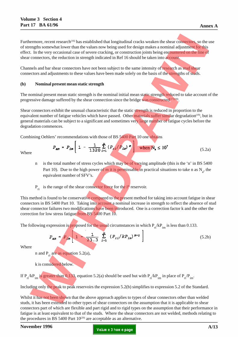
Combining Oehlers’ recommendations with those of BS 5400 Part 10 one obtains
Where
n is the total number of stress cycles which may be of varying amplitude (this is the ‘n’ in BS 5400
Part 10). Due to the high power of m it is permissable in practical situations to take n as Na, the
equivalent number of SFV’s.
Pri
is the range of the shear connector force for the ith reservoir.
This method is found to be conservative compared to the present method for taking into account fatigue in shearconnectors in BS 5400 Part 10. Taking into account a nominal increase in strength to reflect the absence of studshear connector failures two modifications have been introduced. One is a correction factor k and the other thecorrection for low stress fatigue from BS 5400 Part 10.
The following expression is proposed for the usual circumstances in which Pri/kP
im is less than 0.133.
Where
n and Pri are as equation 5.2(a),
k is considered below.
If Pri/kP
im is greater than 0.133, equation 5.2(a) should be used but with P
ri/kP
im in place of P
ri/P
im.
Including only the peak to peak reservoirs the expression 5.2(b) simplifies to expression 5.2 of the Standard.
Whilst it has not been shown that the above approach applies to types of shear connectors other than weldedstuds, it has been extended to other types of shear connectors on the assumption that it is applicable to shearconnectors part of which are flexible and part rigid and to rigid types on the assumption that their performance infatigue is at least equivalent to that of the studs. Where the shear connectors are not welded, methods relating tothe procedures in BS 5400 Part 10(20) are acceptable as an alternative.
(5.2a)
A/13
(5.2b)
Annex AVolume 3 Section 4
Part 17 BA 61/96
November 1996ELECTRONIC COPY NOT FOR USE OUTSIDE THE AGENCY.PAPER COPIES OF THIS ELECTRONIC DOCUMENT ARE UNCONTROLLED
There is however as yet no evidence, despite unforeseen increases in HGV loading, that any fatigue failures ofshear connectors have occurred in bridges, either for road or rail traffic. The new fatigue criterion will generallybe found to be less restrictive than the rules in the Design Code for most composite bridges as they are arelatively new form of construction, there being few composite bridges constructed in the UK before 1950. Theclause however may be found to be more conservative than the rules in the Design Code which are nearer the endof their fatigue design life than any are believed to be at present.
Should a structure fail the assessment criterion the measures proposed are:-
(i) conduct an inspection to determine if the bond has been broken.
(ii) when the bond has not been broken, a situation considered to exist in the majority of composite
bridges (but see 5.2.6(b)), and subject to TAA approval, Pri may be reduced by a factor of 1.15 for
stud shear connectors and 1.25 for other connectors(18). This is the factor k in Equation 5.2 of theStandard.
(iii) take into account other forms of incidental shear connection or other incidental strengthening as maybe appropriate to the bridge.
(iv) when the bond has been broken, friction may be used in assessing the effect of imposed load onshear connectors, and a coefficient of friction of 0.40 is suggested.
(v) review the latest literature, because this is a subject on which research can be expected to continue,as the cumulative damage law for shear connectors of equation 5.2 differs from that for most othermaterials, for which the resistance reduces significantly only towards the end of the design life.
A possible rule for calculating Na is that the number of years in the following periods should be multiplied by(21).
1925 to 1950 by 1/51950 to 1965 by 1/31965 to 1975 by 1/21975 to 1990 by 2/3
Due to the high power of m (5.1) it is not necessary to consider all reservoirs. For a fatigue reservoir of a depthof 40% of the peak to peak range the effect for an equivalent number of occurrences is only 2 - 3% of the peak topeak values. It is therefore permissible to neglect fatigue reservoirs more shallow than this depth.
The new approach would, if so required, enable the remaining life of the structure to be determined.
For assessment, checks on the fatigue endurance of shear connectors in accordance with BS5400 Part 10 are notrequired.
(c) Strength of connectors not included in table 5.1
See comments in 5.3.2.4.
A/14

Volume 3 Section 4Part 17 BA 61/96 Annex A
November 1996 ELECTRONIC COPY NOT FOR USE OUTSIDE THE AGENCY.PAPER COPIES OF THIS ELECTRONIC DOCUMENT ARE UNCONTROLLED
(d) Strength of connectors not complying with 5.3.3.3
Shear connectors not satisfying 5.3.3.3 are essentially of two types:-
(i) there are connectors similar in form to complying connectors, except that they lack the capacity toresist uplift, which were assumed in the design to be shear connectors;
(ii) there are shallow devices projecting into the slab from the beam which were not considered to beshear connectors in the original design.
In the Standard the two types are considered by the same approach (see 5.3.3.8), except that with the veryshallow connectors larger safety factors are required and that without other devices to resist the uplift they offerlittle shear resistance at ULS.
5.3.2.4 Tests on shear connectors
(a) Nominal initial mean static strengths
When tests are performed the initial mean static strength is taken as the lowest test result of three specimens orthe average of a group of five or more. Clearly five will generally be preferable when new testing is undertaken,but existing test data is likely to relate to only three specimens.
(b) Details of tests
The standard push test in the Design Code is reproduced in the Standard. Larger test specimens are nowspecified in BS 5950 Part 3.1 and in Eurocode 4, Part 1.
Eurocode 4 includes a push test which is suitable for shear connectors lacking uplift capacity and this is includedhere in figure 5.6. It is not included in the Standard as it may need to be modified for use with shallow incidentalshear connectors. The type of modification which may be necessary is in the form of additional horizontalrestraints. Until such time as such modifications have been incorporated in the method the intended use of themethod shall be included in the AIP document together with any preliminary tests proposed, or they shall besubsequently agreed with the TAA.
A/15

Annex AVolume 3 Section 4
Part 17 BA 61/96
November 1996ELECTRONIC COPY NOT FOR USE OUTSIDE THE AGENCY.PAPER COPIES OF THIS ELECTRONIC DOCUMENT ARE UNCONTROLLED
h
0.2 l
0.4 l
0.4 l
Steel section
Concrete slab
Recess optional
Gypsum/motar
b
p p
Notes
(1) Reinforcement as in beams assessed.
(2) Steel section to have flanges representative of those to which the shear connectors are attached in the beam.
(3) l = s/0.4 where s = connector spacing.
(4) b = width of connector plus 500mm, or any dimension up to the minimum effective breadth.
(5) h = greater of 150mm or height of connector plus 50mm or any dimension up to the minimum depth of the slab.
(6) Where there is a haunch this should be represented.
Figure 5.6 Test specimen for specific push test
/mortar
A/16
Volume 3 Section 4Part 17 BA 61/96 Annex A
November 1996 ELECTRONIC COPY NOT FOR USE OUTSIDE THE AGENCY.PAPER COPIES OF THIS ELECTRONIC DOCUMENT ARE UNCONTROLLED
5.3.3 Assessment of shear connection
5.3.3.5 Assessment resistance of shear connectors
The design longitudinal shear resistance of a connector Ps, disregarding γ
f3, is
Pam
/ γ slip
where γ slip
is a reduction factor to ensure that slip is not excessive, which in 4.1.2 is assigned a value of 1.375.
The maximum value Pam
permitted by equation 5.2 is 0.82Pim
, so that the maximum value of Ps is 0.82P
im/1.375
or 0.60Pim
, in which 0.60 is the figure in 4.3.2(e). It only applies when the risk from fatigue is low, as when the
fatigue risk is high the first criterion in equation 5.2 gives a lower value of Pam
.
5.3.3.6 Shear connector spacing and longitudinal shear resistance
For the purposes of assessment the rules for calculating the connector forces have been developed to cover anyspacing of shear connector groups as follows(22):-
(1) not greater than 1000mm nor span/20(2) exceeding 1000mm but less than span/8(3) exceeding span/8
The VAy/I method is used for (1) and may be used for (2), but a more accurate result is obtained for (2) using theapproach required for (3).
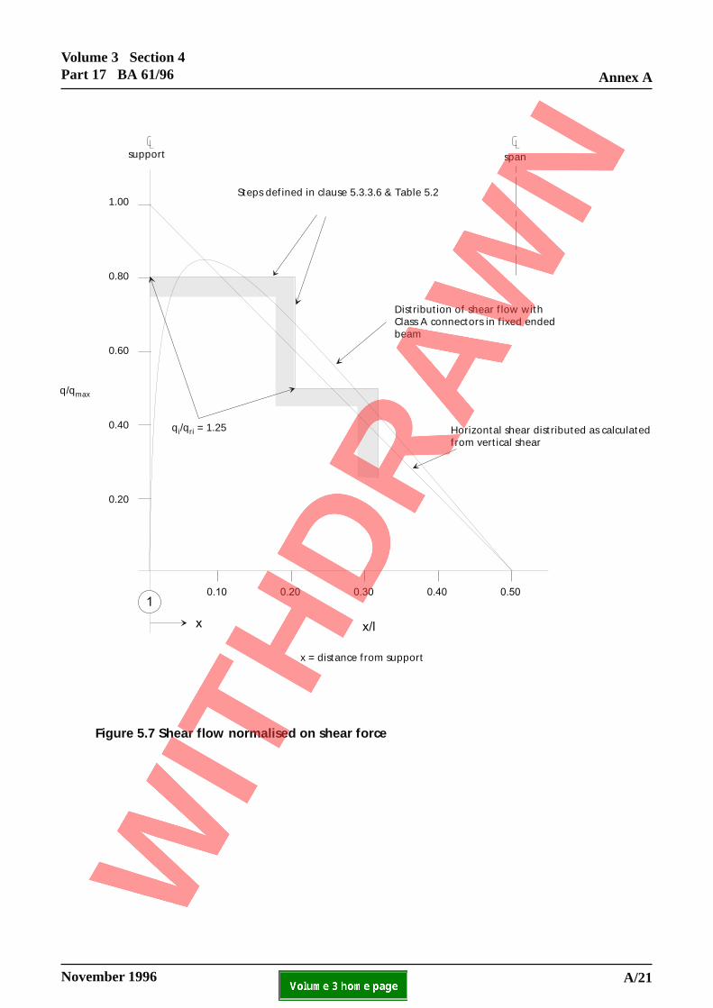
(1) is the normal situation for which, in the Design Code, q/qr is 1.0 at the end of a span and 1.10 elsewhere, with
the maximum values maintained over 10% of the span. For assessment these restrictions have been relaxed bytaking advantage of the flexibility of shear connectors and the facts that at internal supports (see figure 5.7):
(i) where the spans are similar the shear connectors under dead load are undeflected (due to symmetry)and so unloaded, and;
(ii) the horizontal forces in the shear connectors at the ends are redistributed as a result of the sheardeflection of the steel beam.
The values of q/qr take into account variation in the ratios of adjacent span lengths up to 1.50, with a reasonable
allowance for distributed live load effects, but not concentrated loads. If account has been taken of cracking thevalues in table 5.2 would be appreciably greater.
Table 5.2 was determined from finite element analyses of bridges with spans between 10 and 25 metres, andClass a shear connectors were assumed to be studs with a stiffness of 200kN/mm(13)(23) whereas Class b and cconnectors were assumed to be rigid. The stiffness of the shear connection increases as the number of shearconnectors increases, which reduces the redistribution of longitudinal shear along the span in continuous beams.In simply supported beams the redistribution due to flexibility is small and may be adverse, but there will besome benefit from shrinkage, so there is a small net benefit. Class a shear connectors allow up to 20 number19mm studs per metre, which have a stiffness per metre run of 4000kN/mm (or 4000MN/m). In fact the benefitfrom shear connector flexibility reduces only slowly with increase in stiffness and if the stiffnesses specified for
class a connectors were doubled, q/qr values would be mid way between those for class a and b shear connectors
in table 5.2.
A/17

Annex AVolume 3 Section 4
Part 17 BA 61/96
November 1996ELECTRONIC COPY NOT FOR USE OUTSIDE THE AGENCY.PAPER COPIES OF THIS ELECTRONIC DOCUMENT ARE UNCONTROLLED
Shear connectors in beams in which the steel beam to slab depth ratio is less than 2.2 are excluded from class adue to the increased tendency of large tensile forces developing in the shear connectors with reduction in thedepth of the steel beam from end effects in simply supported beams and from shear deflection in continuousbeams.
For (2) q/qr must not exceed unity and the shear connector force needs to be estimated for the distribution of the
shear flow mid way between adjacent groups of shear connectors such that the force in the ith shear connector is
Psi q
ri d
x, as shown in figure 5.8.
For connector spacings exceeding span/8 the method in (2) may not provide an accurate estimate of the connectorforces for concentrated loads (though it has been shown to give a good indication of the shear connector forcesunder uniform loading up to a spacing exceeding span/4). For this situation an analysis is required in which thesteel beam and concrete slab are modelled as separate members connected rigidly at the position of the shearconnectors. For beams of normal span there is little advantage with such connector spacings of including theeffect of connector flexibility. Furthermore for most situations in which these conditions apply the connectors arelikely to be rigid (see 5.3.3.8).
5.3.3.7 Uplift on shear connectors
In deriving the uplift forces on the shear connectors in unstiffened girders from differential bending of adjacentgirders it is acceptable to disregard the stiffness of the web, so that the slab/beam connection is assumed to bepinned in the transverse direction. With stiffened webs however, particularly in the deeper beams, the effect ofthe rigidity of the connection may be significant and therefore should be evaluated.
Shear connectors may also subject to significant direct tension due to slab tie-down forces, particularly severe inthe corners of some skew slabs. Another common situation which causes uplift in shear connectors occurs wherethere are composite cross girders which do not extend outside the external main girders, ie, the cantilever is aconcrete slab. Parapet impact combined with accidental wheel loading can cause significant uplift in shearconnectors on the crossbeam near its junction with the main beam.
5.3.3.8 Incidental shear connection
The method for assessing the strength of incidental shear connectors is derived from the method for barconnectors in Eurocode 4. The method gives appreciably lower strengths than those in table 5.1 for bar
connectors and an additional safety factor γ b introduced for incidental shear connectors which has the values:
1.25 for bolt heads, plate ends and other vertical surfaces2.00 for rivet heads
These values have been derived from an assessment of the relative efficiency of these devices compared to shearconnectors satisfying the requirements of 5.3.3.7.
Attention is drawn to the increased stresses in many bolt groups resulting from their action as shear connectors,and frequently this action would appear to increase the shear in half the bolts and reduce it in the other half(compare figures 5.9a and 5.9b). Possible actions then are:
(i) assess the spare capacity in the bolts and take this as the limiting capacity of the group of incidentalshear connectors;
(ii) assess the bolts taking into account the extra force from the incidental shear connection;
(iii) disregard the incidental action on the grounds that bolt failure of this kind has never been attributedto incidental action;
> Σ_
A/18

Volume 3 Section 4Part 17 BA 61/96 Annex A
November 1996 ELECTRONIC COPY NOT FOR USE OUTSIDE THE AGENCY.PAPER COPIES OF THIS ELECTRONIC DOCUMENT ARE UNCONTROLLED
(iv) take full advantage of the incidental shear connection and ignore its possible adverse effects for thereasons given under (iii).
The procedure adopted should be included in the AIP document or otherwise agreed with the TAA.
Consideration has been given to specifying an upper limit to the increase in the resistance permissible withincidental shear connections. For tall devices, which may be effective as shear connectors but for their lack ofcapacity to resist uplift forces, and which were probably designed as shear connectors, no upper limit is imposed.Provisional limitations to the increase in the capacity of the steel beam permissible for bolts and other verticalbearing surfaces of 40%, and for rivet heads of 33%, are to be used until more accurate values can be justified.
For tall devices formed of plate which are clearly not rigid it is proposed that Pim
given by equation 5.6 is
multiplied by a factor k which is the ratio of the area of plate which under the design pressure (Pam
/A1) deflects
by no more than 0.2mm to the total area of the plate.
In checks assuming devices act as incidental shear connectors unpropped construction is appropriate, so thesedevices carry no longitudinal shear under the self weight of the structure. They may however be assumed to beeffective in carrying longitudinal shear from the superimposed dead load.
(a) Provision of devices to resist uplift
In riveted or bolted construction, composite action can be ensured by replacing some of the rivets or bolts bylong bolts(25) or other suitable devices, as shown in figure 5.10. This would provide a nominal uplift capacity atpositions where the analysis showed this to be most effective. Each scheme needs to be assessed on its merits,taking into account that the passage of a concentrated load will tend to cause uplift in the shear connectors at allpositions. The frequency of the position of restraint to uplift therefore must ensure:
(i) the capacity of the slab to carry the load to where the uplift is resisted;
(ii) that significant vertical separation between the slab and the beam cannot occur.
For this purpose a maximum separation of 0.5mm disregarding the loading on the slab is suggested.
Where the whole of the deck is replaced, the replacement of rivets or bolts can be done on a more systematicbasis.
For heavily trafficked bridges there is advantage to be gained by providing devices to resist uplift which do notthemselves carry longitudinal shear, since the longitudinal shear significantly reduces their capacity to resistuplift (see 5.3.3.7). Fewer devices would then be needed.
Where the girders are of cast or wrought iron, careful consideration should be given to the selection ofconnectors; there may be reasons for preferring mechanical fixings (as in figure 5.10) to welded fixings in thissituation.
(b) Buckle plates and troughs
The undulation of the concrete surface in contact with the steelwork in construction using buckle plates andtroughs constitutes a potential shear connection. The connectors between these features and the steel beamshould be capable of carrying the longitudinal shear force calculated assuming full interaction.
A/19
Annex AVolume 3 Section 4
Part 17 BA 61/96
November 1996ELECTRONIC COPY NOT FOR USE OUTSIDE THE AGENCY.PAPER COPIES OF THIS ELECTRONIC DOCUMENT ARE UNCONTROLLED
5.3.3.8.3 Testing
When appreciable dependence is being placed upon the strength of the incidental shear connection (here definedas increasing the flexural strength of beam by 25% or more) field tests are required to demonstrate the existenceof flexural stiffening effects. It may be assumed for the purpose of interpreting the results that 50% of theincrease in flexural stiffness is attributable to increase in strength, or 75% when 75% or more of compositeaction is confirmed by strain profiles(46) (See also 5.5.3).
Whilst accidental composite action may often appear to have withstood the test of time it may reduce with timedue to slip or corrosion. Therefore, when compliance with the assessment criteria is dependent on accidentalshear connectors, the bridge should be tested periodically under identical live loading to determine whether or notthe stiffness of the bridge is diminishing. Where such a testing programme is adopted and finishes, furniture andparapets are replaced, tests should be conducted before and after the replacement.
5.3.3.9 Partial interaction
For short span beams with Class a connectors two effects combine which improve the overall efficiency ofcomposite beams.
(i) the deflection of flexible shear connectors not only redistributes but also significantly reduces thelongitudinal force, but the reduction in the moment of resistance of the composite section in bridgesof normal span designed for full interaction (as in the Design Code) is too small to justifyconsideration;
(ii) continuous beams with elastic shear connectors possess the ability to redistribute the longitudinalshear force along the shear connection in such a way as to reduce the maximum shear flow inbridges of normal spans designed for full interaction (as in the Standard)(13)(26). The amount ofredistribution is significant even when the shear connectors remain elastic, but in continuous shortspan beams without point loads a substantially uniform distribution of shear flow occurs, and avirtually uniform distribution is obtained with minimal inelasticity in the shear connection.
The procedure adopted is to assess the moments and forces using the short term modulus of elasticity and then toreduce the modulus of elasticity such that the force in the slab is not less than “p” times the value obtained usingthe short term modulus. The entire cross section is then checked for this slab stiffness.
5.3.3.10 Modification of horizontal force for concentrated load
The method in 5.3.3.9 is very conservative for point loads close to the supports and very low values of “p” maybe obtained analytically. Unfortunately, for point loads at mid-span the method of estimating the effectivebreadth in composite construction underestimates the true effective breadth, and strictly Appendix A of BS 5400Part 3 should be used in this situation. Equation 5.11 has therefore been modified to take account of the fact thatthere are likely to be other point loads nearer mid-span, for which the method presented would be otherwise beunsafe.
A/20
Volume 3 Section 4Part 17 BA 61/96 Annex A
November 1996 ELECTRONIC COPY NOT FOR USE OUTSIDE THE AGENCY.PAPER COPIES OF THIS ELECTRONIC DOCUMENT ARE UNCONTROLLED
Steps defined in clause 5.3.3.6 & Table 5.2
Distribution of shear flow with Class A connectors in fixed ended beam
Horizontal shear distributed as calculated from vertical shear
0.20
0.40
0.60
0.80
1.00
support span
0.10 0.20 0.30 0.40 0.50
q/qmax
qi/qri = 1.25
x = distance from support
x/l
1
x
Figure 5.7 Shear flow normalised on shear force
A/21

Annex AVolume 3 Section 4
Part 17 BA 61/96
November 1996ELECTRONIC COPY NOT FOR USE OUTSIDE THE AGENCY.PAPER COPIES OF THIS ELECTRONIC DOCUMENT ARE UNCONTROLLED
Figure 5.8 Calculation of shear connector force when S Span/8
(a) Bolt distortion due to flexure (b) Bolt distortion due to incidental shear connector action
Figure 5.9 Interaction of bolt forces from flexure and incidental shear connector action
Unloaded end of plate
Loaded endof plateConcrete slab
dx
l
Support Support
A/22

Volume 3 Section 4Part 17 BA 61/96 Annex A
November 1996 ELECTRONIC COPY NOT FOR USE OUTSIDE THE AGENCY.PAPER COPIES OF THIS ELECTRONIC DOCUMENT ARE UNCONTROLLED
RivetsBuckle plate
Top flange
Figure 5.10 Typical device to resist uplift
Long bolts or other suitable devices to replace rivets as required
A/23
Annex AVolume 3 Section 4
Part 17 BA 61/96
November 1996ELECTRONIC COPY NOT FOR USE OUTSIDE THE AGENCY.PAPER COPIES OF THIS ELECTRONIC DOCUMENT ARE UNCONTROLLED
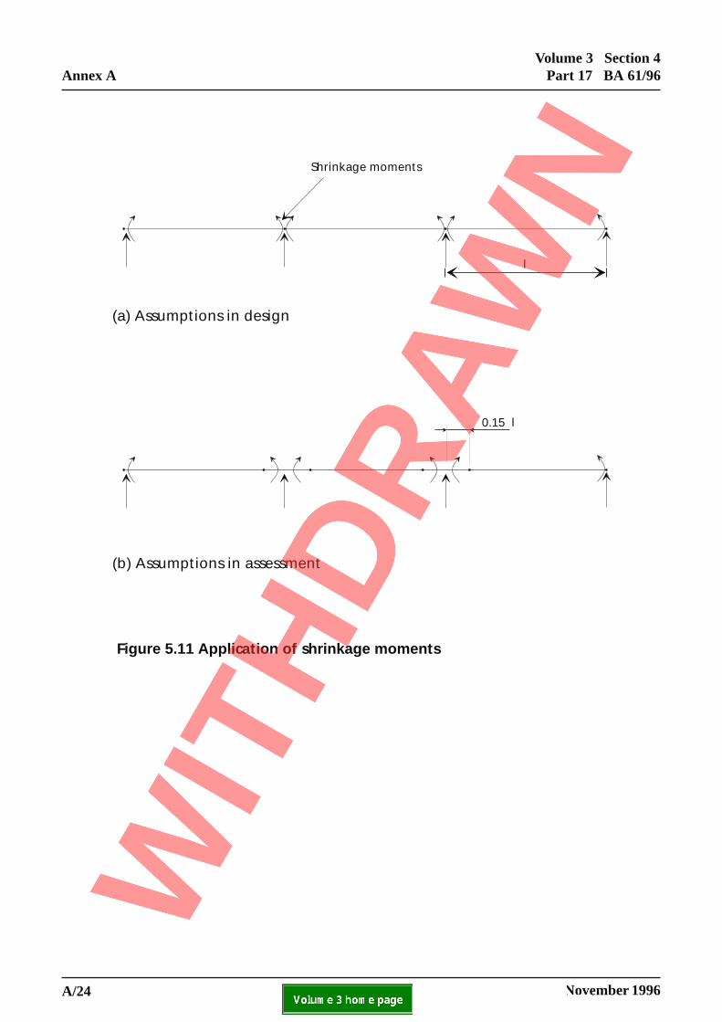
Shrinkage moments
(a) Assumptions in design
(b) Assumptions in assessment
0.15 l
l
Figure 5.11 Application of shrinkage moments
A/24
Volume 3 Section 4Part 17 BA 61/96 Annex A
November 1996 ELECTRONIC COPY NOT FOR USE OUTSIDE THE AGENCY.PAPER COPIES OF THIS ELECTRONIC DOCUMENT ARE UNCONTROLLED
5.4 Temperature Effects, Shrinkage Modified by Creep and Differential Settlement
5.4.1 General
Whilst there is no justification for completely eliminating temperature effects and shrinkage modified by creep inassessment, their effect can be modified such that they are less onerous than in the design situation. Thejustification for this is in part that the design situation specified is very conservative, having to take account ofthe worst likely situation (which is usually more severe than the actual situation) and in part the very fewoccurrences of damage to structures attributed to thermal and shrinkage effects.
Measures taken to relax the severity of the measure in this Clause are as follows:
(i) include differential settlement and shrinkage only in the load combination which includestemperature, so these effects are excluded for the combination with the highest load factors on deadand live load, which tends to be critical;
(ii) assume that concrete cracked in tension is unable to carry thermal and shrinkage strains, and thatthe moment from these effects are applied to the beam at 0.15l(10) from the supports, as shown infigure 5.11 (see 5.4.2.1). In fixed ended beams this reduces the support moment due to shrinkageby 30%; and
(iii) in the calculation of Ls in equation 5.1, reduce the concentrated loading from temperature and
shrinkage at simply supported ends of span by 20% for class a connectors and 10% for class bconnectors (see 5.4.2.2.).
5.4.2 Temperature Effects
5.4.2.3 Longitudinal shear
There is a problem inherited from CP117 Part 2 in relation to the K values which appear unconservative, butmodifications based upon more accurate theory are overconservative. This is that the present requirements allowfor only 1.67 shear connectors per metre, whereas in practice at the ends of beams there are likely to be 10 to 25connectors/metre(13). For shrinkage such a reduction could be attributed to early age effects, but if this was thecase then the shrinkage force would be many times too high. Such a justification for the use of the specified Kvalues for shrinkage is not applicable to their use for temperature, for which they can only be justified on thegrounds that:
(i) Differential temperature movements in the sense which increases forces in connectors at the free endare generally much less than the shrinkage movements (which occur in the opposite direction).
(ii) Dif ferential temperature movements which occur in the sense which increase moments at thepenultimate support are unloading the end shear connectors, so due to inelastic effects, the stiffnessis lower.
A/25
Annex AVolume 3 Section 4
Part 17 BA 61/96
November 1996ELECTRONIC COPY NOT FOR USE OUTSIDE THE AGENCY.PAPER COPIES OF THIS ELECTRONIC DOCUMENT ARE UNCONTROLLED
5.4.4 Differential Settlement
Following the principles in Ref 27, that the normally smaller SLS effects can be disregarded for assessmentunless they are unusually large, differential settlements should be disregarded unless they significantly affect thecalculation. As a guide for assessment, the effects need only be considered when the flexural moments exceed10% of the sum of the moments from dead and live loads, or alternatively where there are physical signs thatsettlement has occurred. Such signs are excessive cracking, relative settlement between columns, abutments andthe carriageway, and bearing distortion. Sometimes, when excessive cracking has occurred and excessive dryingshrinkage is considered unlikely, support settlement is the most likely cause. Attempts should then be made toestimate the magnitude of differential settlement as it may have a significantly adverse effect on the stress statein the bridge.
5.5 Deflections
5.5.1 General
See comments in 4.3.1.
5.5.2 Elastic Deflection
The importance of shear deflection of the webs of steel beams is disregarded in conventional steelworkcalculations, but its effect has been shown to be very significant in continuous beams. For typical continuouscomposite beams with a span to steel beam depth ratios of 20 and 27 the shear deflection in cracked analysesincreases the deflection by 22% and 13%, and it is very much higher both for lower span/depth ratios and if theuncracked, or partially cracked, state of the concrete is taken into account. In simply supported beams the effectis still significant, increasing the deflection typically by 25% at an l/d ratio of 10, 9% at an l/d ratio of 20 and6% at an l/d ratio of 6. The shear deflection is generally more significant in composite beams than steel beamsbecause the shear stress in the webs is higher.
However, deflections of all bridges tend to be significantly less than theory predicts, which is due, inter alia, tounintended composite action, unintended lateral distribution (eg, from erection bracing which has not beenremoved) and from bearing restraint (the effect of which is often large). Unless advantage is taken of suchunintended composite action, the shear deflection may be disregarded.
Unintended composite action includes not only the effect of incidental shear connectors but also the stiffeningeffects of the carriageway and the parapets. This is why in 5.3.3.8.3 of this Advice Note only a proportion of theincreased stiffness found in tests may be attributed to incidental shear connectors. However the stiffening fromthe carriageway and parapet are significantly enhanced by the incidental shear connection, so these effects maybe indicative of its occurrence.
What is unknown, when incidental shear connection is justified by testing, is how close is the condition to thefailure of the shear connection. For this reason special care should be taken to ensure structures with incidentalshear connectors are not overloaded, either during the test or as a result of change of traffic usage.
A/26
Volume 3 Section 4Part 17 BA 61/96 Annex A
November 1996 ELECTRONIC COPY NOT FOR USE OUTSIDE THE AGENCY.PAPER COPIES OF THIS ELECTRONIC DOCUMENT ARE UNCONTROLLED
6 ASSESSMENT OF SUPERSTRUCTURE FORTHE ULTIMATE LIMIT STATE
6.1 Analysis of Structure
6.1.1 General
Shrinkage, temperature and differential settlement effects may be disregarded at the ULS except for the mostslender cross sections.
6.1.3 Composite action
Composite action from incidental connectors at ULS is only permitted where separation is taken into account andwhen the connectors can resist the bending due to separation. Separation at ULS is most likely to occur underheavy axle loads, and adjacent to any cross sections at which inelastic rotation has occurred. It is howeversufficient for the purposes of the calculation to assume elastic conditions throughout and model the structure asdiscussed in 5.3.3.6, but using an iterative procedure in which connections are removed when the deflectionexceeds 0.50mm, which with adjustment to the resistance could be relaxed to a significant proportion of thedepth of the connectors, or when the moment exceeds their flexural capacity.
Lift off is unlikely to occur over appreciable lengths of beam, even under the effect of concentrated loads. Thisis because away from the immediate vicinity of these loads the self weight of the slab will ensure the slab is incontact with the beam. For this reason shallow incidental shear connectors may be assumed to provide lateralrestraint to the top flange at ULS, even though composite action may be inappropriate for the design of the crosssection.
6.1.4 Distribution of bending moments and vertical shear forces
6.1.4.2 Redistribution of support moments in principal longitudinal members
In Eurocodes 3 and 4 there are four classes of cross section which compare with two in BS5400 Part 3,described as compact and non-compact. The finer cross section classification permits a more economicalcalculation procedure to be defined for many cross sections, and BD 56 has followed Eurocode 3 in dividingcompact cross sections into those suitable and those unsuitable for plastic analysis.
Plastic global analysis is not used in the Standard for two reasons, as follows:
(1) the rules necessary for plastic analysis of composite beams have onerous restrictions, whichseverely restrict their usefulness in the assessment of UK bridges. One is effectively a requirementthat most of the loading is uniformly distributed and there are others restricting the ratios ofadjacent span lengths. Of these the former is the most restrictive in application to UK bridges.Furthermore the rules were derived for beams of uniform cross section, although this is not alimitation on the method.
(2) The method in assuming unlimited redistribution of support moments results in the ULS becomingless critical than the SLS, to the extent that the assessment relies upon the SLS check forsatisfactory performance of the bridge, rather than in ensuring against severe infringements of theSLS condition - the most appropriate approach for assessment.
A/27

Volume 3 Section 4Part 17 BA 61/96
November 1996A/28
Annex A
In Eurocode 4 the cross section classes determine a number of aspects of the calculation, but they have beenadopted in the Standard purely to define the amount of redistribution permitted, and, to avoid confusion with thecompact and non-compact definitions in BD 56, they are described as “cross section redistribution classes”. Thevalues in the table for cracked analysis are intended (in Eurocode 4) to give comparable results to those foruncracked analysis; it is likely however that in the larger bridges, when the strength of the steel section by itself ishigh in comparison to that of the composite cross section, that the uncracked analysis, after momentredistribution, will result in lower support moments. Therefore as an interim measure until more preciseguidance can be offered the amount of redistribution made when spans exceed 30m has been reduced, and whenspans exceed 45m cracked analysis is required.
The cross sections are defined by the more critical of the web and compression flange cross section slenderness.For assessment, having redistributed the moments, one has the option for the more compact cross sections ofdesigning them elastically or plastically (see 6.2.2), and for this reason the cross section classes are defined bothin terms of the elastic and plastic stress distribution. The limits for the elastic redistribution have been derivedsuch that they approximately agree with those for the plastic redistribution in table 6.4, which differentiatesbetween cross section classes 1, 2 and 3 only in terms of the plastic cross section, and so the values in table 6.3are an approximation to those in table 6.4, which may be used instead, even if an elastic cross section check isintended. However for plastic assessment of the cross section table 6.3 may not be used.
The use of an elastic cross-section check for cross-sections at which the degree of moment redistribution ensuresplasticity within the cross-section effectively introduces a degree of partial shear connection equivalent to that forfull interaction and an even lower degree where 5.3.3.9 applies.
Moment redistribution is restricted to beams of substantially uniform cross-section throughout each span. Thereason for this restriction is that a unit moment at supports produces a greater support rotation in a beam with areduced mid span cross-section than in a beam of uniform cross-section over its length. The degree of momentredistribution is related to the hinge rotation capacity and upon there being spare flexural capacity at the morecritical cross-sections in adjacent spans. For spans in which the cross-sections are non-uniform the permittedredistribution at a support could be taken as k times the value in table 6.1 where:
k =end rotation of beam B under unit moment at that supportend rotation of beam A under unit moment at that support
where beam A is the actual beam, but which may be considered fixed at the remote end of the span,beam B is a beam with the second moment of area of the support cross-section uniform across the spanand with the same fixity at the remote end as beam A.
However k may be taken as unity where the second moment of area of the cracked support cross-section does notexceed the second moment of area at the mid span cross-section.
6.1.4.3 Redistribution of span moment in principal longitudinal members
In assessment of bridges for HB vehicles there may be some benefit to be gained for redistributing mid-spanmoment to the support. For beams in which the cross section varies substantially the correction in 6.1.4.2 doesnot apply but, where the support sections are stiffer, the permitted degrees of redistribution may be applied to thespan section. When this is done the ratio of adjacent span lengths should satisfy the requirements for plasticanalysis in Ref 28.

Volume 3 Section 4Part 17 BA 61/96 Annex A
November 1996 ELECTRONIC COPY NOT FOR USE OUTSIDE THE AGENCY.PAPER COPIES OF THIS ELECTRONIC DOCUMENT ARE UNCONTROLLED
6.1.5 Temperature effects, shrinkage modified by creep and differential settlement
Where there are no obvious construction defects and no appreciable transverse loads on the girder then therequirement from BD 56 that shrinkage should be included when
is onerous and in most circumstances may be relaxed to:
and may be disregarded in bridges more than 15 years old entirely if the condition is considered good.
See also comments under 6.1.
6.1.6 Shear resistance of composite beams
As the web may have been weakened by corrosion it is advantageous if the contributions of the slab to the shearresistance is taken into account. Tests show that for shear, composite beams may be designed disregarding theinteraction of shear and moment. However the tests were confined mainly to beams in which the ratio of the slabdepth to the girder depth was rather greater than in bridges with steel girder depths greater than 800mm, and thisis taken into account in the assessment rules. This assumes concrete deck thicknesses of about 230mm.(29)
The rule for shear interpolates between a condition of no moment-shear interaction for a steel beam with a depthof 800mm and the normal design situation in BS5400 Part 3 in a steel beam with a depth of 1600mm.
An alternative procedure is allowed whereby the shear in the steel beam is reduced by the shear carried by theslab in a finite element analysis in which the slab is modelled by plate elements. It is suggested that cracking inthe slab can be adequately taken into account by reducing the stiffness of the slab over a length of 0.15l from thesupports to two thirds of that of the cracked slab disregarding tension stiffening. This method is not permittedwhen the moment redistribution taken exceeds that permitted for a beam in cross section redistribution class 2.For this method the moment/shear interaction expressions of BD 56 must be used.
The coincidental direct tension in the slab reduces its shear strength and must be taken into account. The shearstrength is first estimated using BD 44, and the reduction due to the tension should be based on the latest editionof AASHTO(30).
6.2 Analysis of Sections
6.2.2 Bending resistance of compact sections
The coefficient in the concrete term is increased from 0.60 and 0.67. The earlier value was based on a concrete
stress block of 0.40fcu
, whereas 0.45fcu
is used in column design in the Design Code and in the more accuratestress block of BS 8110. It is noted that, based on studies by Stark (31), Eurocode 4 uses a higher concretestrength than Eurocode 2.
Lateral-torsional buckling is disregarded in the assessment of composite beams with compact cross sectionswhen the shear connectors have adequate capacity to resist uplift forces, when U-frame action exists.
Compact beams with incidental shear connectors however are subject to lateral torsional instability and theyshould be checked in accordance with Appendix B.
Whether the composite cross section or the steel cross section alone is employed in the check depends uponcriteria given in 6.1.3 of the Standard. With shallow devices extra ties may be required if it isrequired to assume the entire cross section is composite.
A/29
Annex AVolume 3 Section 4
Part 17 BA 61/96
November 1996ELECTRONIC COPY NOT FOR USE OUTSIDE THE AGENCY.PAPER COPIES OF THIS ELECTRONIC DOCUMENT ARE UNCONTROLLED
6.2.3 Bending resistance of non-compact sections
When the steel section comprises a UB, UC or similar section with equal flanges of strength not exceeding 355N/mm2 and certain other conditions (unrelated to the cross section slenderness) are satisfied, lateral torsionaleffects can be disregarded. The conditions were derived by consideration of Appendix B, but taking into account
work by Weston, Nethercot and Crisfield(32) which shows that lateral torsional buckling can be disregarded for
λLT
values up to 60, which includes all UB sections not exceeding 355 N/mm2. It will be found that for a veryfew cross sections Appendix B gives slightly lower strengths than the method of 6.2.3.3, even when all theconditions on 6.2.3.3 are satisfied.(33)
6.3 Longitudinal Shear
6.3.1 General
A check is required on the strength of the shear connectors at ULS on spans where cross sections are assumed inthe assessment to be plastic(46), but no check is required on spans where the beam is assumed to be elasticthroughout. Shear connector will also have to be checked at ULS if stresses are redistributed from the web ortension flange or if there is uplift in the connectors. When cross sections are designed plastically, thecompression force in the concrete in the sagging moment region and the tensile force in the reinforcement in theadjacent hogging moment region (which act in the same direction) are combined, and a check is made that thereare sufficient shear connectors between the two sections to resist this force.
When stud shear connectors or other flexible shear connectors are used, there is sufficient redistribution of thelongitudinal force between the shear connectors to obviate the need to check the distribution of longitudinal shearunder this condition. When the shear connectors are rigid a different situation exists and the condition could besomewhat more critical. However, there is no known evidence suggesting that a beam designed for the elasticlongitudinal shear distribution at SLS performs poorly at ULS, so no check is required.
The longitudinal shear force from a concentrated load is uniform between the load and the adjacent supports,both in the plastic and elastic design of the longitudinal shear connection, so it is unlikely to be critical at ULSprovided the yield moment is not exceeded. No check at the load is then required. If, however, the yield momentis exceeded, due to the absence of a recognised intermediate state of plasticity, a plastic hinge must be assumedunder the point load. This is likely to produce a more critical condition for the check on the longitudinal shearresistance.
The effective breadth used in determining the longitudinal shear may now be taken as the quarter span values,except for very wide slabs.
The plastic capacity provides an upper limit to the longitudinal shear force calculated elastically. This situationis only likely to be realised where there are deep edge beams integral with the slab.
A/30

Volume 3 Section 4Part 17 BA 61/96 Annex A
November 1996 ELECTRONIC COPY NOT FOR USE OUTSIDE THE AGENCY.PAPER COPIES OF THIS ELECTRONIC DOCUMENT ARE UNCONTROLLED
6.3.3 Transverse reinforcement
6.3.3.1 Definition and general requirements
The rules for transverse reinforcement in the Design Code require broadly similar amounts of transversereinforcement to the rules in Eurocode 2 (for reinforced concrete) which is used in design to Eurocode 4(34). Theareas of transverse reinforcement required by these codes are very much higher than those required by BS8100(35), in which the minimum transverse reinforcement in the slabs of T beams is 0.15%, which is placed nearthe top surface. The same quantity of reinforcement is required for mild steel, high yield steel, smooth bars anddeformed bars. The amount specified is the same as in CP 114(36), the code of practice used in designing concretebuildings in the 1960’s (and for minor structures until more recently), but it had been increased to 0.30% (withsimilar lack of qualification) in CP 110(37), issued in 1972. The drafting committee of BS 8110, which replacedCP 110 in 1985, chose to revert to the earlier values on the practical consideration that no problems were knownto have resulted from this aspect of construction in building structures designed to CP 114.
The satisfactory performance of building structures designed to CP 114 and BS 8110 is attributed to the fact thatthe cracking of the slab parallel to the face of the beam is never sufficient to significantly reduce the longitudinalshear resistance of the beam below its uncracked strength, which is so high, at least with good concrete, as to beable to carry the longitudinal shear without assistance from the reinforcement. The rules in the Design Code andEurocode 2(38) however are based on tests in which large cracks had been induced along the sides of the beams(by high slab loading), a degree of cracking only to be expected when the slab was on the point of failure. BS8110, therefore, effectively recognises the practicality of a situation that is likely to occur in bridges. BS5400Part 4 requires the same minimum amount of transverse reinforcement as BS 8110, but, on account ofconsiderations unrelated to the strength of the shear connection, slabs designed to BS5400 Part 4 usually havemuch more reinforcement than the minimum requirement for transverse reinforcement.
When shear connectors are grouped such that the spacing exceeds span/8 the bursting stresses on the concrete arelikely to be higher than when the connectors are more uniformly distributed. Strictly successive stress blocks, asused for end block design(39) need to be considered to ensure that splitting does not occur. This approach does notwork well for shear connections as the transverse tensile stress on the bearing side of a loaded area is greatestover a distance of 0.2d to 2.0d(7), and for 19mm studs this zone is about 0 to 50mm in front of the bearing face ofthe stud. There is however no requirement for transverse reinforcement over this distance, but reinforcement isnevertheless likely within 100mm of the bearing face.
For this reason the alternative approach has been adopted, of preventing splitting in the general vicinity of theshear connectors by requiring that the longitudinal shear due to the group is carried over a limited distance on thecompression side of the group of shear connectors, using the normal design expression of the Standard.
The indirect tensile forces from incidental shear connectors are lower than those from other shear connectors.The requirement for longitudinal shear resistance carried locally is therefore reduced.
A/31
Annex AVolume 3 Section 4
Part 17 BA 61/96
November 1996ELECTRONIC COPY NOT FOR USE OUTSIDE THE AGENCY.PAPER COPIES OF THIS ELECTRONIC DOCUMENT ARE UNCONTROLLED
A/32
>/
>/
>/
8 CASED BEAMS AND FILLER BEAMCONSTRUCTION
8.1 Scope
8.1.1 Introduction
There is a problem in the assessment of filler beams and cased beams that, if plastic cross section analysis is tobe permitted at ULS, the longitudinal shear strength of the steel/concrete interface is likely to be exceeded.
However, for filler beams the situation is somewhat different as tests have been conducted on constructionwithout transverse reinforcement, or with reinforcement inadequate to satisfy the requirements of 8.3.2, toindicate the plastic design of the composite cross section at ULS is achievable. In a form of filler beamconstruction developed in France (41), which includes special details and transverse prestressing, no check isrequired on the local bond stress at either SLS or ULS. However until such time as longitudinal shear in fillerbeams has been researched a check on the longitudinal shear on planes of type 6 and 7 in figure 8.3 is required asa safeguard against possible failure modes not yet observed.
8.1.2 Cased beams
Cased beams exist which do not comply with the requirements of the Standard, and reduced interface shears areappropriate for less efficient casings and partial casings which do not have efficient confining reinforcement andmay be entirely unreinforced. These are types B, C and D in figure 8.2. Permissible interface bond strengths atSLS for these beams are as follows (N/mm2):
A. (As in Standard) 0.10 √ fcu
but 0.70N/mm2
B. 20mm ≤ cover ≤ 50mm 0.07 √ fcu
but 0.40N/mm2
C. 0.06 √ fcu
but 0.35N/mm2
D. Cover ≤ 50mm 0.10 √ fcu
but 0.50N/mm2
For cased beams of types A and C the checks required are as follows. Partial shear connection calculationsshould assume plastic methods of cross section design and a ductile shear connection. The equilibrium method isthe method of Clause 5.5.2 of Ref 28 or the ‘plastic theory’ method of Clause 6.2.1.2 of Ref 4. The linearinterpolation method is the more conservative method of Clause 6.2.1.2 of Ref 4. In the bond strength expression
fcu
is the worst credible cube strength in N/mm2 and the longitudinal shear stress on the shear connection at ULSfor both methods is taken as not more than 0.50N/mm2.
For spans exceeding 12m the bond stress at SLS should not exceed the permissible bond strength given abovenor 0.5N/mm2. At ULS the moment of resistance should be taken as the yield moment.
For spans between 6m and 9m the permissible bond strengths should not be exceeded at SLS. At ULS themoment of resistance should be assessed as the greater of the yield moment and the flexural resistance assumingpartial shear connection by the linear interpolation method.
For spans less than 6m the permissible bond strength at SLS should not be exceeded. At ULS the moment ofresistance should be assessed as the greater of the yield moment and the flexural resistance assuming partialshear connection by the equilibrium method. The following conditions apply:
>/

Volume 3 Section 4Part 17 BA 61/96 Annex A
November 1996 ELECTRONIC COPY NOT FOR USE OUTSIDE THE AGENCY.PAPER COPIES OF THIS ELECTRONIC DOCUMENT ARE UNCONTROLLED
(i) Where the moment of resistance is taken as the yield moment the design strength of the metal shouldnot be taken greater than 275N/mm2.
(ii) The moment of resistance for cased beams type B should not be taken greater than the yieldmoment.
(iii) The moment of resistance for beams type D should not be taken greater than the lower of themoment at bond failure and the moment of resistance calculated in accordance with chapter 6 of theStandard assuming full composite action. A check at SLS is not required.
(iv) The moment of resistance for beams of types A, B and C may be assumed to be the yield momentwhere this is sufficient to satisfy the assessment loading.
(v) These rules do not apply to cased beams where the soffit of the slab is above the top flange of thesteel beam by more than 25mm.
(vi) In beams with abnormal concrete depths above the metal beam the depth of concrete used incalculation should be restricted such that the elastic neutral axis lies within the depth of the steelsection.
(vii) As an alternative to (vi) the full depth of concrete may be assumed and the metal beam concentratedat the centroid of the steel section.
8.1.3 Complying filler beams
This section considers only filler beam construction in which the transverse reinforcement is adequate to resistthe moments obtained from orthotropic plate or conventional grillage analysis. For this situation it isrecommended that orthotropic plate analysis is adopted for analysis, but grillage representations, allowing for thedifferent stiffness transversely and longitudinally, are an acceptable alternative. The transverse distribution rulesof BA 16 are inappropriate for this form of construction.
The method in 8.3.2 of the Standard, which gives transverse distribution rules for 45 units of HB loading, shouldnow be regarded as a Category A alternative (see Foreword). However providing the conditions in 8.3.2(b) and(d) are satisfied:
(i) the transverse hogging moment may be taken as 10% of the maximum sagging moment, and
(ii) it may be assumed that there is a linear reduction in the transverse sagging moment in the 2m sidestrips as specified in the Standard.
Filler beams may be assessed assuming the principles in 8.1.2, but the stress on the shear connection at ULStaken as 1.4 times the values for cased beams type A and:
For spans exceeding 8m the permissible bond strength should not be exceeded at SLS and the flexural capacity atULS should be assessed as the greater of the yield moment and the flexural resistance assuming partial shearconnection by the linear interpolation method.
For spans less than 8m the permissible bond strengths at SLS should not be exceeded at SLS and the flexuralcapacity at ULS should be assessed as the greater of the yield moment and the flexural resistance assumingpartial shear connection by the equilibrium method.
Alternatively for beams satisfying 8.3.2(c) of the Standard the moment of resistance may be assumed to be thefull plastic moment of resistance without a check on the bond stress at ULS, provided the yield stress of the metalbeam used in the calculation is not greater than 275N/mm2 and provided 8.1.2(vi) is satisfied or provided there is
A/33

Annex AVolume 3 Section 4
Part 17 BA 61/96
November 1996ELECTRONIC COPY NOT FOR USE OUTSIDE THE AGENCY.PAPER COPIES OF THIS ELECTRONIC DOCUMENT ARE UNCONTROLLED
A/34
not more than 75mm of concrete above the top flange of the steel section. Where of these conditions only8.3.2(c) of the Standard is not satisfied the moment of resistance may be taken as the yield moment.
8.1.4 Non-complying filler beams
For beams not complying with 8.3.2 of the Standard, providing there is no evidence of excessive corrosion,fretting action or cracking (in the case of cemented materials) sufficient to adversely affect the achievement ofcomposite action, Clauses 8.1, 8.3, 8.4, 8.5.1 and 8.5.2 apply.
In filler beams without transverse reinforcement, the lateral distribution of load is greater than that suggested bygrillage analysis with pinned transverse members. To reproduce the actual distribution the flexural stiffness ofbeams should be based on the composite cross section, and the torsional stiffness of internal beams taken as thatof the rectangle of concrete horizontally between mid span of adjacent infill elements and vertically between theflanges of the steel beam. Suitable grillages for analyzing filler beam decks are shown in figure 8.4, where themember properties to be assumed are shown in Table 8.1. In using the grillage in figure 8.4(b) the torsion perunit width is to be taken as the sum of the torsions per unit width in the two directions. The two grillages givesimilar distributions of bending moments and torsions, but that in figure 8.4(b) allows lateral distribution ofreactions, whereas in the grillage in figure 8.4(a) allows none (as the method of BD 16).
Table 8.1 Cross Section Properties for Global Analysis of Non-complying Filler Beams
Lateral Distribution of Reactions:Disregarded Included
Main beams
I Icomposite
Icomposite
J Jsteel
Jsteel
A* Acomposite
or ∞ Acomposite
or ∞
Intermediate beamsI - 0
J - Jconcrete
A* - Aconcrete
or ∞
Transverse beams
I 0 Iconcrete
J J Jconcrete
A* Aconcrete
or ∞ Aconcrete
or ∞
* Analysis is insensitive to A
The grillage in figure 8.4(b) should only be used where the abutments are sufficient to resist the torsions, acondition which may be assumed providing.
(a) The abutments are in good condition and not sufficiently cracked so as to relieve torsion moments,and
(b) the slab should project a distance equal to the depth of the metal beam past the end of the beam, or
Volume 3 Section 4Part 17 BA 61/96 Annex A
November 1996 ELECTRONIC COPY NOT FOR USE OUTSIDE THE AGENCY.PAPER COPIES OF THIS ELECTRONIC DOCUMENT ARE UNCONTROLLED
(c) the concrete in the deck should be monolithic with a substantial abutment beam of depth not lessthan 50% greater than the depth of the filler deck, or
(d) the concrete in the deck should be monolithic with a concrete abutment.
In assessing the results of the analysis, the flexural resistance may be assumed to be the same as for complyingfiller beams providing the effective concrete is restricted for torsion to that within a depth above the steel beamsoffit of 1.5 times the depth between the flanges. For flexure 8.1.2(vi) applies (the alternative in 8.1.2(vii) doesnot apply). The torsional strength of the concrete may be taken as
Dense brickwork filler beams with the mortar fully bonded to the bricks and the steel beams shall be assessed inaccordance with above provisions except the bond stress in 8.5.1 shall be taken not greater than 0.3N/mm2, theresistance of attachments shall not be taken greater than 60% of the value in 5.3.3.8.1 and moment of resistanceshould not be taken in excess of the yield moment.
When the brickwork is not bonded to the steel beams, similar provisions apply except that the bond shall be takennot greater than 0.3N/mm2 and the resistance of attachments shall be taken no greater than 40% of the values in5.3.3.8.1.
8.1.5 Vertical shear resistance
For cased beams and filler beams the shear resistance of cemented material up to 250mm above the level of thesteelwork, and for a width on either side as shown in figure 8.5, may be added to that of the steelwork assuming
a shear strength of concrete vc based on the concrete strength fcu as given in BD 44. Strictly this value appliesonly when there is a small amount of longitudinal reinforcement and for this purpose the steelwork is deemed tobe effective as reinforcement. The shear assumed to be carried by the concrete should not exceed 15% of thetotal shear in cased beams and 30% of the total shear in filler beams.
8.1.6 Procedure when longitudinal shear resistance is inadequate
When the longitudinal shear exceeds the permissible shear stress, composite action should be disregarded and allbeams with fill on both sides should be considered to be compact, irrespective of the cross section slenderness.
8.1.7 Punching shear resistance
The punching shear resistance to a wheel load may be assessed assuming the load is replaced by two strip loads,each of which has the same width and centroid of the part of the load which would be carried by statics to the
supporting beam. The shear may be assumed to be carried over a width equal to the loaded width plus av,
assuming a concrete strength of 2vcd/av, where av is the distance from the strip to the face of the web of theneighbouring metal beam and d is the depth from the surface of the concrete to the lower web/flange intersectionof the metal beam.
For a wheel load on a bay adjacent to an edge beam the resistance should be taken as 70% of that for an internalbay of similar dimensions, unless it can be shown that the horizontal thrust resulting from the arching actionshown in Fig 8.6 can be adequately resisted.
A/35

Annex AVolume 3 Section 4
Part 17 BA 61/96
November 1996ELECTRONIC COPY NOT FOR USE OUTSIDE THE AGENCY.PAPER COPIES OF THIS ELECTRONIC DOCUMENT ARE UNCONTROLLED
A/36
8.1.8 Effect of end restraints and of finishings and infill material not satisfying BD 44
Where tests with vehicles of weight not less than 70% of the assessment vehicle suggest there are significantincidental strengthening effects under four passages of the vehicle, an increase in strength may be taken intoaccount as follows
(i) Effect of end restraint
The effect of end restraint from friction in resisting the resolved longitudinal and transverse forces (ifany are assumed) may be taken into account calculated from the dead loads above the level of the soffit,including that in the abutment beam and a coefficient of friction of:
0.35 for concrete on masonry or masonry on masonry
0.50 for concrete cast on concrete with an unprepared surface
0.60 for concrete cast on concrete with a prepared surface, or monolithic concrete ofstrength not exceeding 20N/mm2
0.75 for monolithic concrete of strength exceeding 20N/mm2
It should be noted that where the abutments are thicker than the slab there may be significant endmoments from continuity with the support, but this should be discounted due to the likely loss of thiseffect when the concrete cracks, unless there is flexural reinforcement present satisfying BD 44.
(ii) Effect of finishings
The contribution of the concrete which would not normally be regarded of structural quality, masonryand well compacted (cohesive or weakly cemented cohesive) material, between and above the steelwork,may be taken into account in the assessment of the effect of live loads of filler beam decks, where it canbe shown that the material is in contact with the full depth of the web or on flat rough concrete surfacesof construction satisfying 8.1.2, 8.1.3 or 8.1.4. An initial elastic cross section analysis is required inwhich such material may be taken into account by assuming
αe
= 15 where there is at least 150mm of concrete above the top flange of the steelbeam, or otherwise
αe
= 30.
The strain at the surface of the carriageway determines the method by which the finishings may be takeninto account in carrying the live load moments as follows:
Multiple passage Single passage Method of takingof vehicles of vehicles finishings into(as at SLS) (as at ULS) account
≤ 350 µε ≤ 500 µε by the analysis just described
≤ 700 µε ≤ 1000 µε by increasing the elastic section modulus
of the steel by (hc + h
s)/h
s
Volume 3 Section 4Part 17 BA 61/96 Annex A
November 1996 ELECTRONIC COPY NOT FOR USE OUTSIDE THE AGENCY.PAPER COPIES OF THIS ELECTRONIC DOCUMENT ARE UNCONTROLLED
In the calculations the dead load should be assumed to be carried by the bare steel section, but thesuperimposed dead load may be carried on a composite cross section satisfying 8.1.2, 8.1.3 or 8.1.4.
The calculation may be used for any purposes for which the results are more economical than themethods of 8.1.2, 8.1.3 and 8.1.4.
In no case should the strengthening effect be taken greater than that suggested by the measureddeflection (or preferably strain) readings nor greater than:
2.5 times the strength of the bare steel section, or
1.7 times the strength of a composite section which satisfies 8.1.2, 8.1.3 or 8.1.4.
In constructions in which shear is critical the effect of finishings should only be taken into account whenapproved.
It is difficult to offer guidance in regard to construction in which it is suspected that the parapets maycarry a significant portion of the bending moment
- A load test might damage the parapet.
- When the deck is less strong than the theory suggests brittle failure could result.
- Where the parapet is well connected to the deck it could sometimes contribute to the strength.
- Substantial parapets can span independently of the deck, thereby removing heavy dead loadsfrom the deck.
Some benefits from the finishings, typically 5 to 10%, is likely when the cross sections are designedplastically, but asphalt or concrete wearing courses may be sufficiently strong to induce bond failure inweaker layers beneath. The top 75mm of the finishings should be disregarded.
(iii) Ef fect of infill material not satisfying BD 44
Suggestions for inclusion at the ULS of the effects of infill material not satisfying BD 44 are presentedin Appendix H, which may be used when approved.
(iv) Combined effects of end restraint, finishes and infill material not satisfying BD 44.
End restraints and either finishes or, where permitted, infill material not satisfying BD 44 may beconsidered to act simultaneously, but account should be taken of the fact that end moments may reducedeflections disproportionately to their increase in resistance to the load. The effect of finishes notsatisfying Appendix H and infill material not satisfying BD 44 may not be combined.
(v) Testing
As an alternative to (i) to (iv), where due to non uniformity of material, doubt as to its quality or wherethese procedures are believed to underestimate the strength, other agreed procedures are permitted. Aprocedure such as that in the second sentence of 5.3.3.8.3 above may be valid, but the increase instrength attributable to increase in stiffness needs to be established.
A/37

Annex AVolume 3 Section 4
Part 17 BA 61/96
November 1996ELECTRONIC COPY NOT FOR USE OUTSIDE THE AGENCY.PAPER COPIES OF THIS ELECTRONIC DOCUMENT ARE UNCONTROLLED
Hogging plateJack arches
Cased beams
50
25
25
Figure 8.1 Filler beams and jack arches
Figure 8.2 Cased and partially cased beams
Filler beams Possible modesneither yet observed
Type CType B Type D
(a) Type of cased beam considered in the standard
(b) Other types of cased beams occasionally encountered
Figure 8.3 Failure modes in longitudinal shear
5 5 76
Type A
Filler beams
e
50
b
A/38

Volume 3 Section 4Part 17 BA 61/96 Annex A
November 1996 ELECTRONIC COPY NOT FOR USE OUTSIDE THE AGENCY.PAPER COPIES OF THIS ELECTRONIC DOCUMENT ARE UNCONTROLLED
(a) Model for static distribution of beam reactions
Figure 8.4 Grillages for the analysis of non-complying filler beams
(b) Model for transverse distribution of beam reactions
Cross members representing slabmodelled as torsion beams
Cross members representing slabwith half torsional stiffness of concrete
Torsion beams midway between steel beams with half torsional stiffness of concrete
Flexural discontinuity
Torsional restraint
Pinned support
Steel beams
Steel beams
A/39

Annex AVolume 3 Section 4
Part 17 BA 61/96
November 1996ELECTRONIC COPY NOT FOR USE OUTSIDE THE AGENCY.PAPER COPIES OF THIS ELECTRONIC DOCUMENT ARE UNCONTROLLED
patch loadingrepresenting wheelload dispersedthrough finishing
= = = =
P/2 P/2
d
av av
Sideways thrust
Figure 8.5 Effective concrete shear area of filler beams
Figure 8.6 Raking strut representation of punching shear
hs
3hs
3be
hs he
Effective concreteshear area
A/40

Volume 3 Section 4Part 17 BA 61/96 Annex A
November 1996 ELECTRONIC COPY NOT FOR USE OUTSIDE THE AGENCY.PAPER COPIES OF THIS ELECTRONIC DOCUMENT ARE UNCONTROLLED
11 COMPOSITE COLUMNS
The Standard is not as comprehensive in its treatment of composite columns as the Design Code and occasionallyrecourse will be necessary to the Design Code, when the strength and safety factors should be adjusted to agreewith the Standard. In particular the Standard does not consider filled tubes subject to bending.
The method for designing cased columns in the Design Code is more elaborate and more conservative than themethod in Eurocode 4 and it is seldom used. A method has been produced(43) which is simpler than either methodand which has been calibrated to give column strengths agreeing with strengths obtained using the Design Codeto the following tolerances:
at normal eccentricities of column 5% unsafe to
load (ex/h
x and e
y/h
y 0.60 for 10% safe
uniaxial bending)
for biaxial bending and at higher 10% unsafe toeccentricities in uniaxial bending 25% safe
This is the basis of the present assessment procedure.
The method is considered to be generally conservative compared to the method in EC4.
≤
A/41

Annex AVolume 3 Section 4
Part 17 BA 61/96
November 1996ELECTRONIC COPY NOT FOR USE OUTSIDE THE AGENCY.PAPER COPIES OF THIS ELECTRONIC DOCUMENT ARE UNCONTROLLED
14 JACK ARCH AND TROUGHCONSTRUCTION
14.1 Jack arch construction
The rules for the assessment of jack arches are the same as those for non- complying filler beams subject to thefollowing modifications:
For the assessment of jack arches with concrete infills Chapter 7 of BA 16 permits the use of Clause 8 of theStandard, but with the simple transverse distribution rules in Chapter 2 of BA 16. Alternatively a globalanalysis may be performed in which the depth of the transverse members is taken as the thickness at the crown ofthe arch plus one fifth of the vertical distance between the crown and the soffit of the steel section(40).
Jack arches may otherwise be assessed as filler beams, but the effective perimeter assumed to provide bondshould be restricted to the upper surface of the top flange and the web where the infill is at least 50mm thick.Also the bond strength at SLS and the stress on the shear connection at ULS reduced by a factor of 1.40 (orsome other agreed factor), and the option of sometimes using the plastic moment of resistance does not apply.
The shear resistance of jack arches may be assumed to be the same as for filler beams in 8.1.5.
The effect of finishings may be taken into account by the method in 8.1.7. When the girders are of cast iron the
values of α e should be halved.
In hogging plate construction, which is the more modern form of jack arch construction (in which the beams aremore likely to be of mild steel than cast iron), the horizontal shear resisted between the hogging plate and the fillshould be disregarded, except where the fill is of concrete when incidental shear connection from rivet (or bolt)heads may be taken into account.
Tie rods are often present in jack arches to resist the arch thrust along the sides of the bridge. The adequacy ofthese should be established.
14.2 Trough Construction
Smooth troughs with ‘open’ profiles have substantially lower incidental strengthening than jack arch or fillerbeam construction, so no alternative assessment procedures to those in BA 16(2) are provided. However wherethere are rivet or bolt heads penetrating concrete overlays the rules for incidental shear connectors in 5.3.3.8 maybe used, and, where the surfaces of the troughs are sufficiently steep that these devices resist uplift, consideration
may be given to reducing values of γ b.
A/42

Volume 3 Section 4Part 17 BA 61/96 Annex A
November 1996 ELECTRONIC COPY NOT FOR USE OUTSIDE THE AGENCY.PAPER COPIES OF THIS ELECTRONIC DOCUMENT ARE UNCONTROLLED
APPENDIX ACRACK WIDTHS IN COMPOSITE BEAMS
A method is given for assessing the crack widths in composite beams which is less conservative than BS5400Part 4, which in the Design Code must be used for assessing crack widths in composite bridges by applying therules for T beams, for which the crack width is:
w = 3acr
m
Two situations are taken into account in the Standard, the first being flexural cracking in a well designed beam.An allowance is made for tension stiffening, which is reduced not only by the reinforcement but also by contactwith the top flange of the steel beam(44). The expression does not take into account the situation in which the topflange is debonded, which is confined to laboratory conditions. The bonded situation is considered moreappropriate to design.
The last term in the tension stiffening expression is a nominal allowance for
(i) the effects of shrinkage, which are not otherwise taken into account,
(ii) the effect of stress attracted to the top flange by the stiffness of the uncracked concrete between thecracks, and
(iii) shear deflection.
The effect of reinforcement which is not parallel to the beam is taken into account by an expression similar tothat in BS5400 Part 4.
The other situation (equation A.2) relates to beams in which the reinforcement is appreciably less than that inbridges designed to BS5400 Part 4. It was derived following a study of crack widths in Austrian compositebridges(45).
A/43
ε
Annex AVolume 3 Section 4
Part 17 BA 61/96
November 1996ELECTRONIC COPY NOT FOR USE OUTSIDE THE AGENCY.PAPER COPIES OF THIS ELECTRONIC DOCUMENT ARE UNCONTROLLED
APPENDIX BLATERAL-TORSIONAL BUCKLING OFCOMPOSITE BEAMS WITH SLAB AND
GIRDERS TIED LATERALLY ANDROTATIONALLY
The method of assessing the effects of lateral torsional buckling is derived from the method of Eurocode 4, but ithas been modified(33):
(i) to give better agreement with the unbraced case when lateral bracing is added to the compressionflange between the support and the point of contraflexure, and
(ii) by combining it with the Perry Robertson expression of BS5400 Part 3, Appendix G(47).
In both respects the method is less conservative than the method of the draft EC4 and is believed to be moreaccurate.
From the assumption made in the derivation of equation B.1 it is reasonable to assume that it may also be usedfor cross sections which have steel members asymmetrical about the x axis and are in redistribution class 3,providing:
(i) bfttft + A
r/1.025 ≥ b
fctfc
(ii) bfttft ≥ 0.60b
fctfc
(iii) fry
/γmr ≥ σ
y /γ
m
It is also reasonable that requirements 7 and 8 in B.2.2 are replaced by conditions (c), (d), (e) (which is 8), (f),(h), (j) and (k) in 6.2.3.3 and providing the steel strength does not exceed 355 N/mm2.
A/44
Volume 3 Section 4Part 17 BA 61/96 Annex A
November 1996 ELECTRONIC COPY NOT FOR USE OUTSIDE THE AGENCY.PAPER COPIES OF THIS ELECTRONIC DOCUMENT ARE UNCONTROLLED
APPENDIX CLATERAL-TORSIONAL BUCKLING OFCOMPOSITE BEAMS WITH SLABS ANDGIRDERS TIED LATERALLY BUT NOT
ROTATIONALLY
C.1 General
C.1.1 Introduction
C.1.1.1 Scope
Even when U-frame action is not present, a significant increase in the flexural resistance of beams is obtainedfrom lateral restraints to the tension flange, because the centre of rotation in lateral torsional buckling is lifted tothe level of the shear connection.
This topic has been extensively researched at the University of Manchester over a number of years, from whichhas been produced a design method published in Appendix G of BS 5950 Part 1(48). The method has beentranslated into the terms used in BS5400 Part 3 and methods have been devised (in C.1.1.2) for employing it inassessing composite beams.
Two situations are taken into account:
(1) the situation in which the beam has devices which act as incidental shear connectors at SLS, butwhich are ineffective at ULS. In this case the method in this Appendix assumes that flexure at ULSis resisted solely by the steel beam, and
(2) the situation in which the beam has deep devices which are similar to shear connectors, except forthe absence of resistance to uplift. In this case the full composite section is assumed to carry theloading at ULS.
BS 5950 Part 1 does not specify the maximum spacing of lateral restraint and instead requires that lengthsbetween lateral restraints are checked as unrestrained non-composite beams. Limited research has establishedthat the method is tolerant to widely spaced restraints and conservatively it is suggested there should be restraintsat the third span positions.
A/45

Annex AVolume 3 Section 4
Part 17 BA 61/96
November 1996ELECTRONIC COPY NOT FOR USE OUTSIDE THE AGENCY.PAPER COPIES OF THIS ELECTRONIC DOCUMENT ARE UNCONTROLLED
APPENDIX DVIBRATION OF COMPOSITE BRIDGES
D.1 Traffic Vibration
Vibration of vehicular bridges due to traffic is not a problem, partly due to the considerable mass of vehicularbridges and partly due to the insensitivity of seated passengers to vibration. For foot and cycle track bridges theproblem is addressed in Appendix B of BS5400 Part 2, as implemented by BD 37 (49).
Vibration is not normally a problem in older bridges as they are generally heavier than modern bridges, althoughon some of the more heavily trafficked it is possible that a degree of loosening of parts of the structure hasoccurred. In this case vibration of those parts is possible. The main concern is with footbridges. Foot and cycletrack bridges need not be checked if the span is less than 35m for simply supported spans or 40m if continuousone or both ends. Highway bridges need not be checked if the span is less than 55m for simply supported spansor 65m if continuous one or both ends. Foot and cycle track bridges with rolled steel beams with non-structuralparapets are particularly prone to vibration problems.
Nevertheless checks should be made on any bridge about which there has been public complaint.
D.2 Aerodynamic Vibration
Aerodynamic criteria are given in BD 49(9). However composite highway bridges need not be checked foraerodynamic effects when two of the three following criteria are satisfied:
(a) the deck widths do not exceed 12m if not more than 10m above ground level, or otherwise 15m,
(b) the edge details satisfy Clause 2.1.3.2 of BD 37 and the overhang should not be less than 0.75d4,
(c) both the following are satisfied:
(i) the super elevation of the line between the top of the facias on either side of the bridge doesnot exceed 1/40, and
(ii) the incident wind within ±45° of the normal to the span is not consistently inclined to thehorizontal (on account of the local topography).
Footbridges need not be checked for spans less than 35m when condition (b) above and (c)(ii) are satisfied;otherwise they need not be checked for spans less than 30m.
Further, vortex shedding need not be considered for any composite bridge of span less than 70m.
These limits are rather greater than the limits advisable for steel bridges as composite decks are very stifftorsionally and therefore are not particularly susceptible to the more dramatic form of vibrational instability.Cable suspension bridges pose particular problems, but are not considered here.
A/46

Volume 3 Section 4Part 17 BA 61/96 Annex A
November 1996 ELECTRONIC COPY NOT FOR USE OUTSIDE THE AGENCY.PAPER COPIES OF THIS ELECTRONIC DOCUMENT ARE UNCONTROLLED
D.3 Cantilevered Footways
Footways cantilevered from vehicular bridges may pose particular problems and should be checked when thelength of the cantilever from the primary beams exceed 10m. Sometimes there is a problem with shortercantilevers, but this is due to interaction with the transverse bending.
D.4 Calculation Procedures
Generally the bridge design codes quoted above should be sufficient, but the information may be supplementedby the procedure in chapter 7.6 of reference 50 and by the use of computer programs, many of which give thefrequencies and shapes of the main modes of vibrations, although with some this facility may require the choiceof particular, and more powerful, types of elements.
There is a problem in continuous bridges of whether the exciting energy is sufficient to excite adjacent spans, aswhen this is the case the effective stiffness of continuous beams reduces to a value similar to that of simplysupported beams. Some account of this is taken in the method of ref 50. More sophisticated use of computers ispermissible to determine the effect of particular excitations, but then the problem is encountered of how best torepresent the excitation.
D.5 Damping Values
It is acceptable to assume a logarithmic decrement of 0.04 for composite bridges, as suggested in BD 37(49).
A/47
Annex AVolume 3 Section 4
Part 17 BA 61/96
November 1996ELECTRONIC COPY NOT FOR USE OUTSIDE THE AGENCY.PAPER COPIES OF THIS ELECTRONIC DOCUMENT ARE UNCONTROLLED
APPENDIX EFATIGUE IN REINFORCEMENT OF
COMPOSITE BEAMS
There are two methods of considering fatigue in reinforcement in BD 44. In the first method, which relates tolocal combination 1 at SLS under HA loading, the permissible stress ranges for unwelded non-corrodedreinforcement under imposed loading are given. In shorter span composite bridges these criteria may becritical(21). In this situation the alternative method which refers to BS5400 Part 10(20) should be used.
Corrosion and manufacturers markings can significantly reduce the resistance to a greater extent than the loss ofbar area might suggest. Such conditions are not specifically taken into account, but could be assumed to be takeninto account in the general conservatism of the first method. For composite beams in which the reinforcement iscorroded, BA 38(52) should be used in estimating the remaining fatigue life.
A/48

Volume 3 Section 4Part 17 BA 61/96 Annex A
November 1996 ELECTRONIC COPY NOT FOR USE OUTSIDE THE AGENCY.PAPER COPIES OF THIS ELECTRONIC DOCUMENT ARE UNCONTROLLED
APPENDIX FREVISIONS IN THE ASSESSMENT RULES
SUITABLE FOR DESIGN
This appendix considers the appropriateness of the technical revision only. Limited improvements in thestructure of the Design Code have been made which are not mentioned.
All reference to “iron” and to “most credible strength” etc are inappropriate to design.
References to BD 44, BD 56 and BD 21 are also inappropriate to a design standard.
The separate identity of partial safety factors, desirable for assessment, is not necessary for design.
4.1.2 Verification of Structural Adequacy. The use of γ mt
in assessing test data is appropriate to design butthe term “worst credible strength” is inappropriate. However consideration should be given to revisingtable 4.2 to give characteristic values.
The consistent use of expression 2b throughout the Standard is appropriate for adoption in the DesignCode.
4.3.1 The last paragraph concerns incidental shear connection and is inappropriate to design.
4.3.2 (b) The coefficient 0.80 is inappropriate to design.
(e) This revision is considered acceptable for the design situation.
5.1.1.1 and 5.1.1.2 These revisions are considered appropriate to design, although the effect of considering veryshort span beams to have cracked supports should be evaluated.
5.2.1 Revision is appropriate to design.
5.2.3.1 Revision is considered appropriate to design.
5.2.3.2 Revision is appropriate to design.
5.2.3.3 Revision is appropriate to design, but further research is needed to establish whether the power of thecosine of the angle, could be reduced to 2.
5.2.5.3 Revision inappropriate to design.
5.2.6.2 and 5.2.6.3 Revision inappropriate to design.
5.3.1 Revisions considered appropriate to design.
5.3.2.1 (b) Revision is considered acceptable for design, but the effect of equation 5.2 near the end of thedesign life needs to be assessed.
(d) Non-complying shear connectors are inappropriate to design.
A/49

Annex AVolume 3 Section 4
Part 17 BA 61/96
November 1996ELECTRONIC COPY NOT FOR USE OUTSIDE THE AGENCY.PAPER COPIES OF THIS ELECTRONIC DOCUMENT ARE UNCONTROLLED
5.3.2.4 (a) The use of the mean for five or more specimens is appropriate to design.
Table 5.1 The strength of stud shear connectors could be increased by about 10%. For the other types ofshear connectors considered the strength quoted could be used.
5.3.3 The revisions in this section are considered inappropriate to design.
5.4 Excepting the revision concerning the effective breadths is 5.4.2.1 the revisions in this chapter areinappropriate to design; however
(1) the effect of shrinkage should be reduced and
(2) the problems noted with the shear connector stiffness in equation 5.12 need to be addressed.
6.1.3 Revision inappropriate to design.
6.1.4.2 Revisions appropriate to design, however it would be better if BS5400 Part 3 introduced four crosssection classifications and then they could be described as “cross-section classes”, rather than cross-section redistribution classes”.
6.1.5 Revision appropriate to design.
6.1.6 Improved version of revision may be appropriate for design.
6.2.1 Revision appropriate to design.
6.3.3 All revisions appropriate to design except 6.3.3.8.
6.3.4 Revision appropriate to design.
8. Revision inappropriate to design, except check on yield stress at serviceability.
9. Revision inappropriate to design.
10. Revision inappropriate to design.
11. Revision appropriate to design, but greater scope of former method requires that it is retained in anappendix.
Appendix A Inappropriate to design, but equation A.1 and A.3 could be used as an interim measure.
Appendix B Appropriate to design, but needs to be modified for U-frame action.
Appendix C Inappropriate for design.
A/50

Volume 3 Section 4Part 17 BA 61/96 Annex A
November 1996 ELECTRONIC COPY NOT FOR USE OUTSIDE THE AGENCY.PAPER COPIES OF THIS ELECTRONIC DOCUMENT ARE UNCONTROLLED
APPENDIX GSIGNIFICANCE OF NOMINAL
CONSIDERATIONS
There are a number of situations in which dimensional and other criteria specified in the Standard may beinfringed without significantly affecting the structural performance, but which in some may significantly affectits rate of deterioration after the assessment. Other criteria may not significantly affect the performance of manystructures. Some aspects of the construction which are clearly satisfactory need only be checked by calculationif there is a likelihood of them becoming affected by a change of use.
The measures to be taken depend upon the category of the infringement as follows:
Category A: Where these criteria are infringed by 20% or more an inspection shall ensure that the concrete hasnot spalled locally as a result of corrosion.
Category B: Where these criteria are infringed the strength may be lower than assumed in the Standard. Wheninfringed the effect on the strength shall be assessed.
Category C: As Category B, but assess only when infringements are greater than 5% (or 7% when they affectareas).
Category D: As Category B, but assess only when infringements are greater than 35%.
The various dimensional criteria of the Standard are categorised as follows:
Clause Category Remarks5.2.6.3 A Check also concrete flange for cracks
figures 5.1, 5.2 C Except for stud dimensions and widths of shear connectorswhich are category B and edge distances which are categoryD
5.3.3.2 C
5.3.3.3(a) C
5.3.3.3(b) D
5.3.3.6(1) B
6.2.3.3 B
6.3.3.1(b) D
figure 6.2 D
6.3.3.7 D
A/51

Annex AVolume 3 Section 4
Part 17 BA 61/96
November 1996ELECTRONIC COPY NOT FOR USE OUTSIDE THE AGENCY.PAPER COPIES OF THIS ELECTRONIC DOCUMENT ARE UNCONTROLLED
8.7.2 D
8.8 A for 50mm dimensionD for 600mm dimension
9.6.4 B If no evidence of honeycombing disregard this limit
11.1.2.2 C
11.3.1 B
11.3.4 B
11.3.9 C
A/52

Volume 3 Section 4Part 17 BA 61/96 Annex A
November 1996 ELECTRONIC COPY NOT FOR USE OUTSIDE THE AGENCY.PAPER COPIES OF THIS ELECTRONIC DOCUMENT ARE UNCONTROLLED
APPENDIX HSUGGESTED PROPERTIES OF INFILL
MATERIAL NOT SATISFYING BD 44 FORTHE ASSESSMENT OF FILLER BEAMS
It is proposed that:
The local bond strength should not be taken greater than the greater of:
(i) for cemented material 1/40 times the compressive strength determined from large diameter cores or largeundisturbed specimens when practical, but not greater than 0.50 N/mm2.
for uncemented material the square root of the product of:
1/40 of the mean of the confined and unconfined compressive strength, and
the shear strength forecast by the principles of soil mechanics.
(ii) The flexural strength should not exceed the strength of the steel cross-section by more than:
35% for cemented materials, or
20% for uncemented materials.
In calculating the resistance of the composite cross section, the part of the fill in tension shall be disregarded and,to provide an additional margin of safety, the depth of the fill in excess of 200mm above the steelwork shall bereduced by:
30% for cemented materials, or
40% for uncemented materials.
Any material below the soffit of the steelwork should be neglected as this is liable to spall.
The approach has not been checked for situations in which the ratio of the depth of fill to the span is such thatarching action in the fill occurs in the direction of the span. For this situation, the fill within the depth of thesteelwork is to be considered as acting compositely with it, and the fill above is to be considered as spanning byarching action and anchored at the ends by friction against the composite section, or by lateral resistance frommaterial of at least similar compressive strength and compaction.
A/53
Annex AVolume 3 Section 4
Part 17 BA 61/96
November 1996ELECTRONIC COPY NOT FOR USE OUTSIDE THE AGENCY.PAPER COPIES OF THIS ELECTRONIC DOCUMENT ARE UNCONTROLLED
APPENDIX IREFERENCES
1. BD 61 “The Assessment of Composite Highway Bridges and Structures”, Design Manual for Roadsand Bridges.
2. BA 44 “The Use of Departmental Standard BD 44 for the Assessment of Concrete Highway Bridgesand Structures”, Design Manual for Roads and Bridges.
3. BD 56 and BA 56 “The Assessment of Steel Highway Bridges and Structures”, Design Manual forRoads and Bridges.
4. Eurocode 4, “Design of composite steel and concrete structures: Part 1-1 General rules and rules forbuildings”, European Pre-standard, Final Draft, prENV 1994-1-1:1002E ECN, April 1992 (BSIDocument No 92/14118 of Committee B/525/4).
5. BS 8110:Part 2: “Structural use of concrete: Part 2: Code of practice of special circumstances”, BritishStandards Institution, 1985.
6. Technical Paper TP12, “Testing of composite bridges”, Background document for BS 5400 Part 5; Usefor Assessment of Bridges.
7. BS5400: Part 4, “Steel, concrete and composite bridge - Part 4: Code of Practice for the design ofconcrete bridges”, British Standards Institution, 1990.
8. Beeby AW. “Cover to reinforcement and corrosion protection”, International Symposium on behaviourof offshore concrete, ARBEM, Brest, 1980.
9. BD 49, “Design rules for aerodynamic effects on bridges”, Design Manual for Roads and Bridges.
10. Technical Paper No 2, “Global Analysis and cross section design - serviceability limit state”,Background Document for “BS5400 Part 5: Use for Assessment of Bridges”.
11. McHardy Young J “Examples of the design of steel girder bridges in accordance with BS 153: Parts 3A,3B and 4 (as at October, 1963)”, British Constructional Steelwork Association”, Publication No 22,1963.
12. Smith DGE, “Effective breadths of reinforced concrete T-beams and composite beams in hoggingmoment regions”, document written in preparing Ref 34.
13. Technical Note No 7, “Partial interaction and assessment of the longitudinal shear connections”,Background document for BS5400 Part 5: Use for Assessment.
14. Oehlers DJ and Johnson RP, “The strength of stud shear connectors in composite beams,” TheStructural Engineer, Vol 65B, No 2 June 1987 pp44-48.
15. Johnson RP and Oehlers DJ. “Analysis and design for longitudinal shear in composite T-beams”, Proc.Instn Civ Engnrs, Pt 2, 71, Dec 1981, pp 989-1021.
A/54

Volume 3 Section 4Part 17 BA 61/96 Annex A
November 1996 ELECTRONIC COPY NOT FOR USE OUTSIDE THE AGENCY.PAPER COPIES OF THIS ELECTRONIC DOCUMENT ARE UNCONTROLLED
16. Oehlers DJ and Park SM, “Shear connectors in composite beams with longitudinally cracked slabs”,Journal of Structural Engineering, ASCE, Vol 118, No 8, August 1992, pp 2004-2022.
17. Oehlers DJ, “Assessing the residual strength of shear connectors in composite bridges”, BridgeManagement 2, Thomas Telford, London, 1993. pp842-851.
18. Technical Paper TP10, “Shear Connectors”, Background document for BS5400:Part 5" “Use forAssessment of Bridges”.
19. Oehlers DJ, “Residual strength of structural components subject to cyclic loads, “Journal of StructuralEngineering, ASCE, Vol 118, No 10, Oct 1992, pp2645-2658.
20. BS5400:Part 10: “Steel, concrete and composite bridges, Part 10. Code of Practice for fatigue”, BSI1980.
21. Technical Paper TP13, “Fatigue in composite beams”, Background document for BS 5400 Part 5: Usefor Assessment of Bridges.
22. Technical Paper No 9, “Incidental shear connectors”, Background document for “BS5400 Part 5: Usefor Assessment of Bridges”.
23. Menzies JB, “CP117 and shear connectors in steel-concrete composite beams made with normal densityor lightweight concrete”, The Structural Engineer, No 3 Vol 49, March 1971, pp137-154.
24. Johnson RP and Buckby RJ, “Composite Structures of Steel and Concrete: Volume 2: Bridges”, Collins,London, 2nd Edition, 1986.
25. Hayward A “Traditional forms of composite construction”, Subcontract Study report prepared for ScottWilson Kirkpatrick by Cass Howard and Partners on behalf of the TRL/DoT, 9 July 1993.
26. Johnson RP, “Loss of interaction in short span composite beams and plates”, Journal of ConstructionalSteel Research, Vol 1, No 2, Jan 1981, pp11-16.
27. BA 34, “Technical requirements for the assessment and strengthening programme for highwaystructures - Stage 1 - Older short span bridges and retaining structures”, Design Manual for Roads andBridges.
28. BS 5950 Part 3, “Structural use of steelwork in building: Section 3.1: Code of Practice for design ofcontinuous composite beams”, British Standards Institution, 1990.
29. Technical Paper No 4, “Global analysis, cross section slenderness criteria and shear at the ultimate limitstate”, Background Document for BS5400 Part 5: Use for Assessment of Bridges.
30. “Standard specifications for highway bridges”, American Association of State Highways andTransportation Officials”, 15th Edition, 1992.
31. Stark JWB, “Rectangular stress blocks for concrete”, Technical Paper S16 for EC4 Drafting Panel, June1984.
32. Weston G, Nethercot DA and Crisfield MA, “Lateral buckling in continuous composite bridge girders”,The Structural Engineer, Vol 69, No 5, 5 March 1991, pp79-87.
A/55

Annex AVolume 3 Section 4
Part 17 BA 61/96
November 1996ELECTRONIC COPY NOT FOR USE OUTSIDE THE AGENCY.PAPER COPIES OF THIS ELECTRONIC DOCUMENT ARE UNCONTROLLED
33. Technical Paper No TP6, “Lateral torsional buckling in composite beams”, Background Paper. BS5400:Part 5: Use of Assessment of Bridges.
34. Smith DGE and Johnson RP, “Commentary on the 1985 draft of Eurocode 4: Composite steel andconcrete structures”, Building Research Establishment, 1986.
35. BS 8110: Part 1, “Structural use of concrete: Part 1: Code of practice for design and construction”,British Standards Institution, 1985.
36. CP 114, “The Structural use of reinforced concrete in buildings”, British Standard Code of Practice,British Standard Institution, 1957.
37. CP 110 Part 1, “The structural use of concrete : Part 1 : Design, materials and workmanship”, BritishStandard Institution, 1972.
38. Eurocode No 2, “Design of concrete structures: Part 1. General rules and rules for buildings”, EuropeanCommittee for Standardisation, Dec 1991. Issued as DD ENV:1992-1-1:1992 together with UKNational Application Document, March 1993.
39. Guyon Y, “Prestressed Concrete, Volume 1 : Simply supported beams”, John Wiley and Sons, 1953.
40. Technical Paper TP11, “Cased beams, filler beams and Jack arches”. Background document forBS5400:Part 5: Use for Assessment of Bridges.
41. “Ponts dalles poutrelles ajoures precontraints” (filler beams), PSI-PAP Guide de conception”, Serviced’Etudes Techniques et des Autoroutes (SETRA), Dec 1985, Bridges Division, part translation byDepartment of Transport, 1993.
42. Ricketts NJ and Low AMC, “The Assessment of Filler beam bridge decks without transversereinforcement”, Transport Research Laboratory, 1993 (In preparation).
43. Johnson RP and Smith DGE, “A simple design method for composite columns”, The StructuralEngineer, Part A, Vol 58A, No 3, March 1980, pp85-93.
44. Technical Paper No 5, “Cracking, tension stiffening and effective breadths in composite beams”,Background Document for “BS 54000 Part 5: Use for Assessment of Bridges”.
45. Randl E and Johnson RP, “Widths of initial cracks in concrete tension flanges of composite beams”,IABSE Proceedings, P54/82, Nov 1982.
46. Technical Paper No TP8, “Design and assessment requirements for longitudinal shear resistance at theultimate limit state”, Background paper for BS5400 Part 5: Use for Assessment of Bridges.
47. BS5400:Part 3, “Steel concrete and composite bridges, Part 3, Code of Practice for the design of steelbridges”, British Standards Institution, 1982.
48. BS 5950 Part 1: “Structural use of steelwork in building - Part 1: Code of practice for design in simpleand continuous construction: hot rolled sections”, BSI, 1990.
49. BD 37 “Loads for Highway Bridges”, Design Manual for Roads and Bridges.
A/56

Volume 3 Section 4Part 17 BA 61/96 Annex A
November 1996 ELECTRONIC COPY NOT FOR USE OUTSIDE THE AGENCY.PAPER COPIES OF THIS ELECTRONIC DOCUMENT ARE UNCONTROLLED
50. Wyatt TA, “Design guide on vibration of floors, The Steel Construction Institute/Construction IndustryResearch and Information Association, Steel Construction Institute, 1989.
51. Tilly GP, “Fatigue classification of steel reinforcing beams”, Transport and Road Research Laboratory,Dept of Transport, Crowthorne, May 1988.
52 BA 38 “Assessment of the Fatigue Life of Corroded or Damaged Reinforcing Bars”, DesignManual for Roads and Bridges.
A/57