Embed Size (px)
Citation preview

Implementing a System-on-Chip using VHDL
Corrado Santoro
ARSLAB - Autonomous and Robotic Systems LaboratoryDipartimento di Matematica e Informatica - Universita di Catania, Italy
S.D.R. Course
Corrado Santoro A VHDL SoC

Our SoC is made of ...
A clock generator, we use the built-in 50 MHz clockprovided in the Altera DE0 boardA CPU, we will use a 32-bit RISC architecture (notpipelined)A ROM, where we will place (statically) our codeA Parallel I/O Port, 32-bit, connected to the 4-digit hexdisplay and to switches and pushbuttons
Corrado Santoro A VHDL SoC

Part I
CPU Architecture
Corrado Santoro A VHDL SoC

Basic CPU Architecture
A 32-bits MIPS-like processor:DATA BUS and ADDRESS BUS are 32-bits wideMemory is organised in words 32-bits wide
Also CPU instructions are 32-bits wideRegisters:
32 general purpose registers R0-R31R0 is read-only and contains always “0” (like the MIPSprocessor)Program Counter (PC), contains the memory address ofthe next instructionInstruction Register (IR), contains the current instruction tobe executed
Corrado Santoro A VHDL SoC

Instruction Set
Basic opcode structureOpcode(6 bits) Additional parameters(26 bits)
Arithmetic/Logic Register-type opcodesOpcode(6) Rs(5) Rt(5) Rd(5) p(11)
”010001”, MOV Rs → Rt (Rd is not used)”010010”, ADD Rs + Rt → Rd”010011”, SUB Rs - Rt → Rd
MOV R1, R2 010001 00001 00010 00000 00000000000ADD R1, R4, R2 010010 00001 00100 00010 00000000000SUB R0, R7, R3 010011 00000 00111 00011 00000000000
Corrado Santoro A VHDL SoC

Instruction Set
Immediate-type opcodesOpcode(6) Rs(5) Rt(5) Immediate(16)
”001000”, ADD I Rs + Immediate → Rt
”001001”, SUB I Rs - Immediate → Rt
”000100”, BEQ, Jump to “Immediate” address if Rs = Rt
”000101”, BNE, Jump to “Immediate” address if Rs not = Rt
”100011”, LW, load word from location Rs + “Immediate” and store it into Rt
”100011”, SW, store word from Rt into location Rs + “Immediate”
ADD I R1, #5, R2 001000 00001 00010 0000000000000101SUB I R0, #12, R7 001001 00000 00111 0000000000001100
Corrado Santoro A VHDL SoC

Instruction Set
Other instructionsOpcode(6 bits) parameter(26 bits)
”000000”, NOP”010010”, JUMP, absolute jump to “parameter” address”111111”, HALT
Corrado Santoro A VHDL SoC

Part II
Hardware Components
Corrado Santoro A VHDL SoC

CPU
clock, input, the main CPU clocknRst, input, hardware RESET, active lowaddress bus, 32-bit, outputdata bus, 32-bit, bidirectionalcontrol bus:
nMemWr, output, active low when a memory write is executednMemRd, output, active low when a memory read is executednHalt, output, active low when the CPU is in the HALT state
Corrado Santoro A VHDL SoC

ROM
clock, input, the main clockaddress bus, 32-bit, input, address to be readdata bus, 32-bit, output, data readnMemRd, input, active low when a memory read is executedThe ROM is designed to contain the software to be executedwhich is hard-coded in the VHDL file.
Corrado Santoro A VHDL SoC

Digital Output Port
clock, input, the main clocknRst, input, RESET, active lowaddress bus, 32-bit, input, address to be writtendata bus, 32-bit, bidirectional, data busnMemWr, input, active low when a memory write is executednMemRd, input, active low when a memory read is executeddata output, 32-bit, output, the data that has been written to the portdata input, 32-bit, input, the data that has been read from the portThe module reacts to memory address 0x8000When a “store” instruction to address 0x8000 is executed, the written dataappears on data output pins.When a “load” instruction from address 0x8000 is executed, the datapresent on data input pins is read.
Corrado Santoro A VHDL SoC

Tri-state Outputs
Corrado Santoro A VHDL SoC

ROM Timings
ROM (and peripherals) synchronises on falling edge of theclock
First the address to be read is set-up on the address bus (by the CPU)Then the nMemRd signal is asserted (by the CPU)At the next falling edge clock, the ROM recognises the nMemRd signaland outputs, on the data bus, the word addressed (event “A”)When the CPU has got the word from the data bus, the nMemRd signal isde-assertedAt the next falling edge clock, the ROM recognises that nMemRd is nomore active and puts the data bus to high impedence (event “B”)
Corrado Santoro A VHDL SoC

The ROM in VHDL�library ieee;...
entity rom isport( data_bus_out: out std_logic_vector(31 downto 0);
address_bus: in std_logic_vector(31 downto 0);nMemRd: in std_logic;clock: in std_logic );
end rom;
architecture rom_arch of rom issignal out_byte: std_logic_vector(31 downto 0);
beginprocess(clock)begin
if (clock’event and clock = ’0’) then -- falling edgeif nMemRd = ’0’ then
case address_bus iswhen "00000000000000000000000000000000" => out_byte <= NOP;when "00000000000000000000000000000001" => out_byte <= ADD_I & R0 & R1 & ...;
...when others => out_byte <= HALT;
end case;else
out_byte <= (others => ’Z’);end if;
end if;end process;data_bus_out <= out_byte;
end architecture;� �Corrado Santoro A VHDL SoC
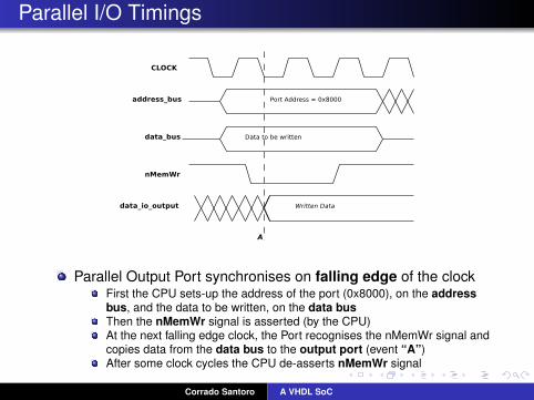
Parallel I/O Timings
Parallel Output Port synchronises on falling edge of the clockFirst the CPU sets-up the address of the port (0x8000), on the addressbus, and the data to be written, on the data busThen the nMemWr signal is asserted (by the CPU)At the next falling edge clock, the Port recognises the nMemWr signal andcopies data from the data bus to the output port (event “A”)After some clock cycles the CPU de-asserts nMemWr signal
Corrado Santoro A VHDL SoC

The Parallel Output Port in VHDL�library ieee;...entity ParallelInOut isport(address_bus: in std_logic_vector(31 downto 0);
data_bus: inout std_logic_vector(31 downto 0);data_output : out std_logic_vector(31 downto 0);data_input : in std_logic_vector(31 downto 0);clock: in std_logic;nMemWr: in std_logic;nMemRd: in std_logic;nRst: in std_logic );end ParallelInOut;
architecture pInOut of ParallelInOut isbegin
process(clock,nRst)begin
if nRst = ’0’ thendata_output <= (others => ’1’);data_bus <= (others => ’Z’);
elsif (clock’event and clock = ’0’) thenif address_bus = x"00008000" then -- address is 0x8000
if nMemWr = ’0’ then data_output <= data_bus;elsif nMemRd = ’0’ then data_bus <= data_input;else data_bus <= (others => ’Z’);end if;
end if;end if;
end process;end architecture;� �
Corrado Santoro A VHDL SoC

Part III
The CPU in VHDL
Corrado Santoro A VHDL SoC

The CPU
It is implemented as a finite-state machine triggered bythe clock signalWhile all peripherals react to falling edge of the clock, theCPU reacts to rising edgeThis is required to meet harware reaction times:
At the rising edge the CPU prepares the signals onaddress/data/control bus to interact with aperipheral/memoryAt the (next) falling edge the peripheral/memory executesthe action on the basis of such prepared signals
States:RESET: entered when nRst is ’0’FETCH 0, FETCH 1: fetch phase, executed in two clockcyclesEXEC: execute phase, with several sub-states on the basisof the instruction of be executedHALT: halt phase, the CPU is stopped
Corrado Santoro A VHDL SoC

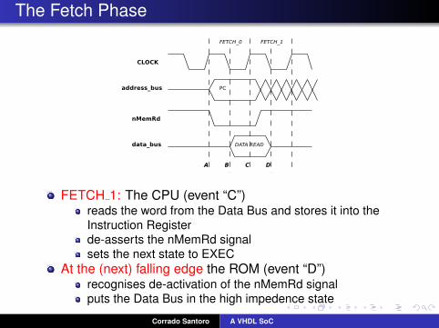
The Fetch Phase
FETCH 0: The CPU (event “A”)outputs the Program Counter to the Address Busputs the Data Bus to high impedenceasserts the nMemRd signalsets the next state to FETCH 1
At the (next) falling edge the ROM (event “B”)recognises the nMemRd signaloutputs the word data to the data bus
Corrado Santoro A VHDL SoC
The Fetch Phase
FETCH 1: The CPU (event “C”)reads the word from the Data Bus and stores it into theInstruction Registerde-asserts the nMemRd signalsets the next state to EXEC
At the (next) falling edge the ROM (event “D”)recognises de-activation of the nMemRd signalputs the Data Bus in the high impedence state
Corrado Santoro A VHDL SoC

The CPU in VHDL (I)
�library ieee;...entity CPU isport(clock: in std_logic;
nRst: in std_logic;data_bus: inout std_logic_vector(31 downto 0);address_bus: out std_logic_vector(31 downto 0);nMemRd: out std_logic;nMemWr: out std_logic;nHalt: out std_logic);
end CPU;
architecture my_CPU of CPU istype state_type is (st_reset, st_fetch_0, st_fetch_1, st_exec, st_halt);type sub_state_type is (exec_0, exec_1);type register_array is array(0 to 7) of std_logic_vector(31 downto 0);signal PC: std_logic_vector(31 downto 0) := (others => ’0’);signal IR: std_logic_vector(31 downto 0) := (others => ’0’);signal REGS: register_array;signal state: state_type := st_halt;signal sub_state: sub_state_type := exec_0;
beginprocess(clock,nRst)
...� �Corrado Santoro A VHDL SoC
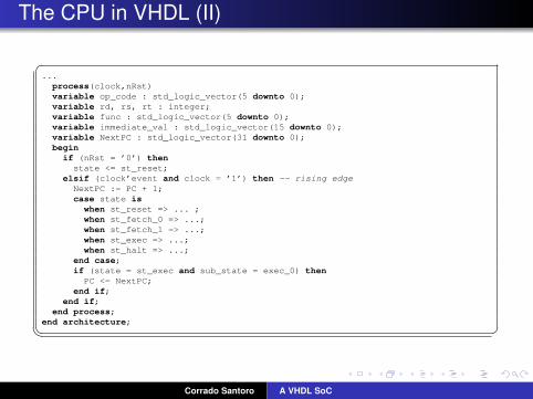
The CPU in VHDL (II)
�...
process(clock,nRst)variable op_code : std_logic_vector(5 downto 0);variable rd, rs, rt : integer;variable func : std_logic_vector(5 downto 0);variable immediate_val : std_logic_vector(15 downto 0);variable NextPC : std_logic_vector(31 downto 0);begin
if (nRst = ’0’) thenstate <= st_reset;
elsif (clock’event and clock = ’1’) then -- rising edgeNextPC := PC + 1;case state is
when st_reset => ... ;when st_fetch_0 => ...;when st_fetch_1 => ...;when st_exec => ...;when st_halt => ...;
end case;if (state = st_exec and sub_state = exec_0) then
PC <= NextPC;end if;
end if;end process;
end architecture;� �Corrado Santoro A VHDL SoC

The CPU in VHDL (III)
�...case state is
when st_reset =>PC <= (others => ’0’);REGS(0) <= (others => ’0’);REGS(1) <= (others => ’0’);REGS(2) <= (others => ’0’);REGS(3) <= (others => ’0’);REGS(4) <= (others => ’0’);REGS(5) <= (others => ’0’);REGS(6) <= (others => ’0’);REGS(7) <= (others => ’0’);nMemRd <= ’1’;nMemWr <= ’1’;data_bus <= (others => ’Z’);nHalt <= ’1’;state <= st_fetch_0;
...� �
Corrado Santoro A VHDL SoC

The CPU in VHDL (IV)
�...case state is
...when st_fetch_0 =>
address_bus <= PC;nMemRd <= ’0’;state <= st_fetch_1;
when st_fetch_1 =>IR <= data_bus;nMemRd <= ’1’;sub_state <= exec_0;state <= st_exec;
...� �Corrado Santoro A VHDL SoC

The CPU in VHDL (V)
�...case state is
when st_exec =>if IR = NOP then
state <= st_fetch_0;else
op_code := IR(31 downto 26);rs := conv_integer(IR(25 downto 21));rt := conv_integer(IR(20 downto 16));rd := conv_integer(IR(15 downto 11));immediate_val := IR(15 downto 0);func := IR(5 downto 0);case op_code is
when MOV => ...;when ADD => ...;...
end case;end if;
...� �Basic structure: Opcode(6 bits) Additional parameters(26 bits)
Arithmetic/Logic Register-type: Opcode(6) Rs(5) Rt(5) Rd(5) p(11)
Immediate-type: Opcode(6) Rs(5) Rt(5) Immediate(16)
Corrado Santoro A VHDL SoC

The CPU in VHDL (VI)�...case op_code is
when MOV =>if rt /= 0 then -- do not write into R0
REGS(rt) <= REGS(rs); -- move from rs to rtend if;state <= st_fetch_0;
when ADD =>if rd /= 0 then -- do not write into R0
REGS(rd) <= REGS(rs) + REGS(rt); -- add rs + rt into rdend if;state <= st_fetch_0;
when SUBT =>if rd /= 0 then -- do not write into R0
REGS(rd) <= REGS(rs) - REGS(rt); -- sub rs - rt into rdend if;state <= st_fetch_0;
...end case;...� �Arithmetic/Logic Register-type: Opcode(6) Rs(5) Rt(5) Rd(5) p(11)
”010001”, MOV Rs → Rt (Rd is not used)
”010010”, ADD Rs + Rt → Rd
”010011”, SUB Rs - Rt → Rd
Corrado Santoro A VHDL SoC

The CPU in VHDL (VII)�...op_code := IR(31 downto 26);rs := conv_integer(IR(25 downto 21));rt := conv_integer(IR(20 downto 16));rd := conv_integer(IR(15 downto 11));immediate_val := IR(15 downto 0);func := IR(5 downto 0);case op_code is
...when ADD_I => -- Add Immediate
if rt /= 0 thenREGS(rt) <= REGS(rs) + immediate_val;
end if;state <= st_fetch_0;
when JUMP => -- jumpNextPC := "000000" & IR(25 downto 0);state <= st_fetch_0;
...end case;...� �Basic structure: Opcode(6 bits) Additional parameters(26 bits)
Immediate-type: Opcode(6) Rs(5) Rt(5) Immediate(16)
”001000”, ADD I Rs + Immediate → Rt
”010010”, JUMP, absolute jump to “parameter” address
Corrado Santoro A VHDL SoC

The CPU in VHDL (VIII)
�...case op_code is
...when SW => -- store word
case sub_state is
when exec_0 => address_bus <= immediate_val + REGS(rs);data_bus <= REGS(rt);nMemWr <= ’0’;state <= st_exec;sub_state <= exec_1;
when exec_1 => address_bus <= (others => ’Z’);data_bus <= (others => ’Z’);nMemWr <= ’1’;state <= st_fetch_0;
end case;...� �Immediate-type: Opcode(6) Rs(5) Rt(5) Immediate(16)
”100011”, SW, store word from Rt into location Rs + “Immediate”
Corrado Santoro A VHDL SoC
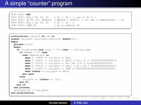
A simple “counter” program�0000 0000: NOP0000 0001: ADD_I R0, R1, #1 ; R1 <- R0 + 1, eqv to R1 <- 10000 0002: SW R0, R1, #0x8000 ; MEM(R0 + 0x8000) <- R1, eqv to MEM(0x8000) <- R10000 0003: ADD_I R1, R1, #1 ; R1 <- R1 + 10000 0004: JUMP #2 ; go to address #2� ��architecture rom_arch of rom issignal out_byte: std_logic_vector(31 downto 0);begin
process(clock)begin
if (clock’event and clock = ’0’) then -- falling edgeif nMemRd = ’0’ then
case address_bus iswhen "..0000" => out_byte <= NOP;when "..0001" => out_byte <= ADD_I & R0 & R1 & "0000000000000001";when "..0010" => out_byte <= SW & R0 & R1 & "1000000000000000";when "..0011" => out_byte <= ADD_I & R1 & R1 & "0000000000000001";when "..0100" => out_byte <= JUMP & "00000000000000000000000010";when others => out_byte <= HALT;
end case;else
out_byte <= (others => ’Z’);end if;
end if;end process;data_bus_out <= out_byte;
end architecture;� �Corrado Santoro A VHDL SoC

Reading Input and display data
�0000 0000: LW R0, R1, #0x8000 ; R1 <- MEM(R0 + 0x8000), eqv to R1 <- MEM(0x8000)0000 0001: SW R0, R1, #0x8000 ; MEM(R0 + 0x8000) <- R1, eqv to MEM(0x8000) <- R10000 0004: JUMP #0 ; go to address #0� ��architecture rom_arch of rom issignal out_byte: std_logic_vector(31 downto 0);begin
process(clock)begin
if (clock’event and clock = ’0’) then -- falling edgeif nMemRd = ’0’ then
case address_bus iswhen "..00" => out_byte <= LW & R0 & R1 & "1000000000000000";when "..01" => out_byte <= SW & R0 & R1 & "1000000000000000";when "..10" => out_byte <= JUMP & "00000000000000000000000000";when others => out_byte <= (others => ’Z’);
end case;else
out_byte <= (others => ’Z’);end if;
end if;end process;data_bus_out <= out_byte;
end architecture;� �Corrado Santoro A VHDL SoC

An “up/down counter” program�0000 0000: NOP0000 0001: ADD_I R0, R1, #1 ; R1 <- R0 + 1, eqv to R1 <- 10000 0002: SW R0, R1, #0x8000 ; MEM(R0 + 0x8000) <- R1, eqv to MEM(0x8000) <- R10000 0003: LW R0, R2, #0x8000 ; R2 <- MEM(R0 + 0x8000), eqv to R2 <- MEM(0x8000)0000 0004: AND_I R2, R2, #1 ; R2 <- R2 and 10000 0005: BEQ R0, R2, #8 ; if R2 = 0 go to #80000 0006: ADD_I R1, R1, #1 ; R1 <- R1 + 10000 0007: JUMP #2 ; go to address #20000 0008: SUB_I R1, R1, #1 ; R1 <- R1 - 10000 0009: JUMP #2 ; go to address #2� ��architecture rom_arch of rom issignal out_byte: std_logic_vector(31 downto 0);begin
process(clock)begin
if (clock’event and clock = ’0’) then -- falling edgeif nMemRd = ’0’ then
case address_bus iswhen "..0000" => out_byte <= NOP;when "..0001" => out_byte <= ADD_I & R0 & R1 & "0000000000000001";when "..0010" => out_byte <= SW & R0 & R1 & "1000000000000000";when "..0011" => out_byte <= LW & R0 & R2 & "1000000000000000";when "..0100" => out_byte <= AND_I & R2 & R2 & "0000000000000001";when "..0101" => out_byte <= BEQ & R0 & R2 & "0000000000001000";when "..0110" => out_byte <= ADD_I & R1 & R1 & "0000000000000001";when "..0111" => out_byte <= JUMP & "00000000000000000000000010";when "..1000" => out_byte <= SUB_I & R1 & R1 & "0000000000000001";when "..1001" => out_byte <= JUMP & "00000000000000000000000010";when others => (others => ’Z’);
end case;else
out_byte <= (others => ’Z’);end if;
end if;end process;data_bus_out <= out_byte;
end architecture;� �Corrado Santoro A VHDL SoC

Implementing a System-on-Chip using VHDL
Corrado Santoro
ARSLAB - Autonomous and Robotic Systems LaboratoryDipartimento di Matematica e Informatica - Universita di Catania, Italy
S.D.R. Course
Corrado Santoro A VHDL SoC