Embed Size (px)
Citation preview
NOC: Networks on Chip SoC Interconnection Structures
COE838: Systems-on-Chip Design http://www.ee.ryerson.ca/~courses/COE838/
Dr. Gul N. Khan http://www.ee.ryerson.ca/~gnkhan
Electrical and Computer Engineering Ryerson University
Overview • Introduction to Networks on a Chip • Bus and Point-to-point NoC Systems • Routing Algorithms and Switching Techniques • Flow Control • NOC Topology Generation and Analysis
Chapter 5: Computer System Design – System on Chip by M.J. Flynn and W. Luk Chapter 12: On-Chip Communication Architectures – SoC Interconnect by S. Pasricha & N. Dutt
NOC and SOC Design 2
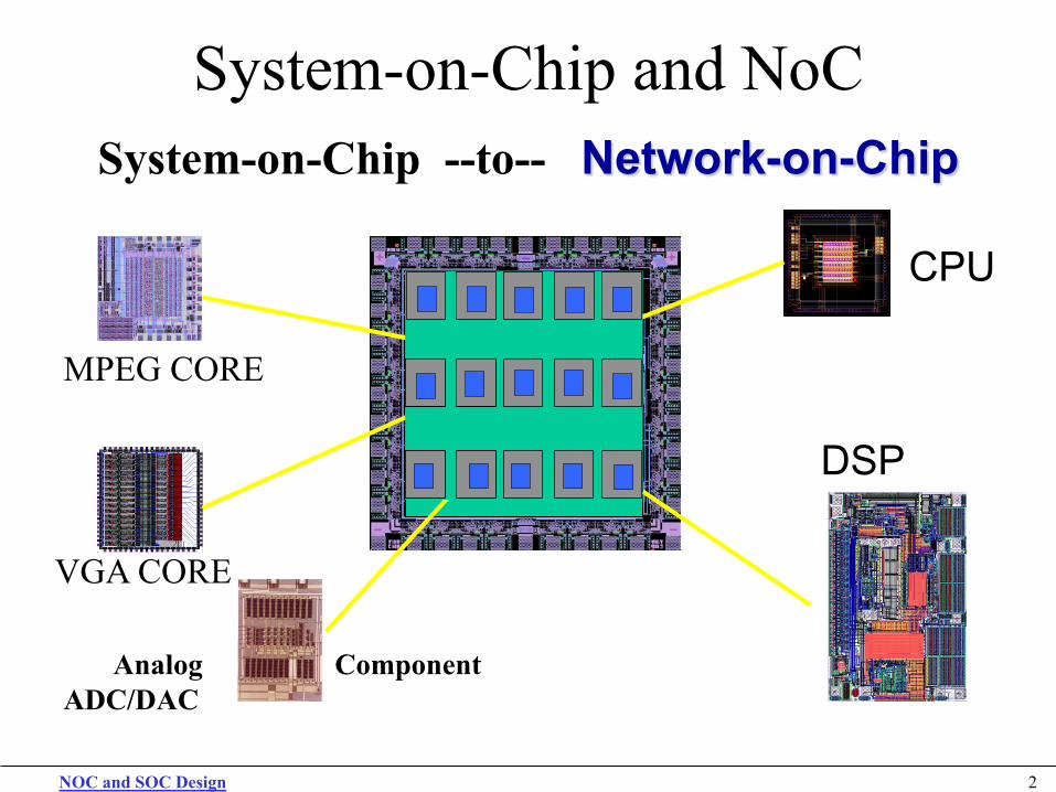
System-on-Chip and NoC System-on-Chip --to-- Network-on-Chip
Analog Component ADC/DAC
VGA CORE
DSP
CPU
MPEG CORE
NOC and SOC Design 3
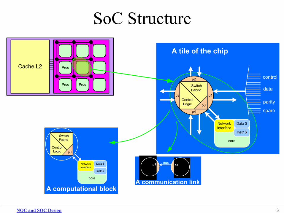
SoC Structure NoC-based System on a Chip
Proc
Proc Proc
Cache L2
A tile of the chip
control
data
spare
parity
A tile of the chip
Instr $
Data $NetworkInterface
p1
p2
p3
p4
Switch Fabric
Control Logic p0
core
control
data
spare
parity
A computational block
Switch Fabric
Control Logic p0
Instr $
Data $NetworkInterface
core
p1 p3bus
A communication link
NOC and SOC Design 4
Multiple Processor/Core SoC
Inter-node communication between CPU/cores can be performed by message passing or shared memory. Number of processors in the same chip-die increases at each node (CMP and MPSoC). • Memory sharing will require: SHARED BUS * Large Multiplexers * Cache coherence techniques * Not Scalable • Message Passing: NOC * Scalable * Require data transfer transactions * Has overhead of extra communication
NOC and SOC Design 5
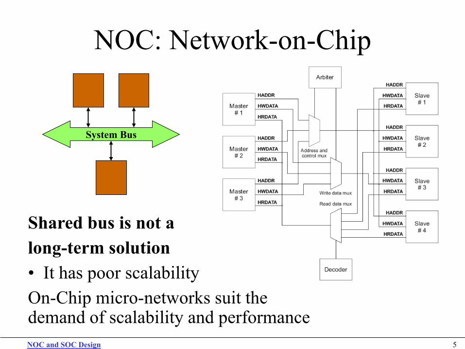
NOC: Network-on-Chip
Shared bus is not a long-term solution • It has poor scalability On-Chip micro-networks suit the demand of scalability and performance
System Bus
NOC and SOC Design 6
NOC and Off-Chip Networks
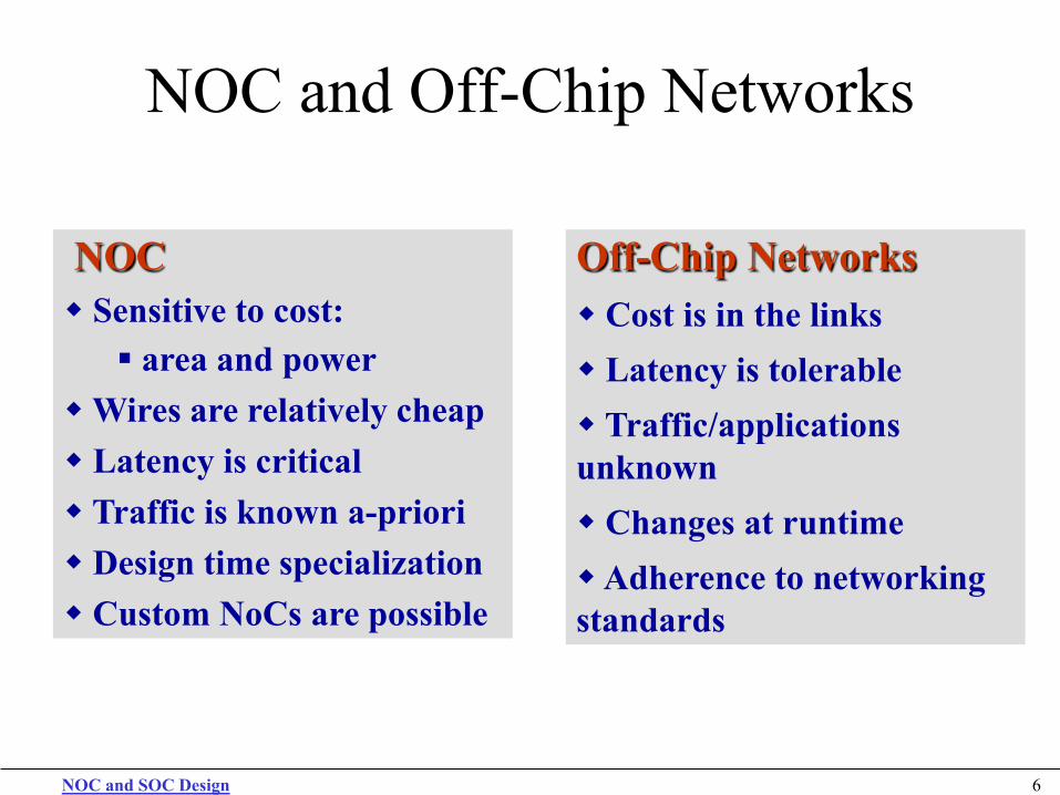
NOC Sensitive to cost: area and power
Wires are relatively cheap Latency is critical Traffic is known a-priori Design time specialization Custom NoCs are possible
Off-Chip Networks Cost is in the links Latency is tolerable Traffic/applications unknown Changes at runtime Adherence to networking standards
NOC and SOC Design 7
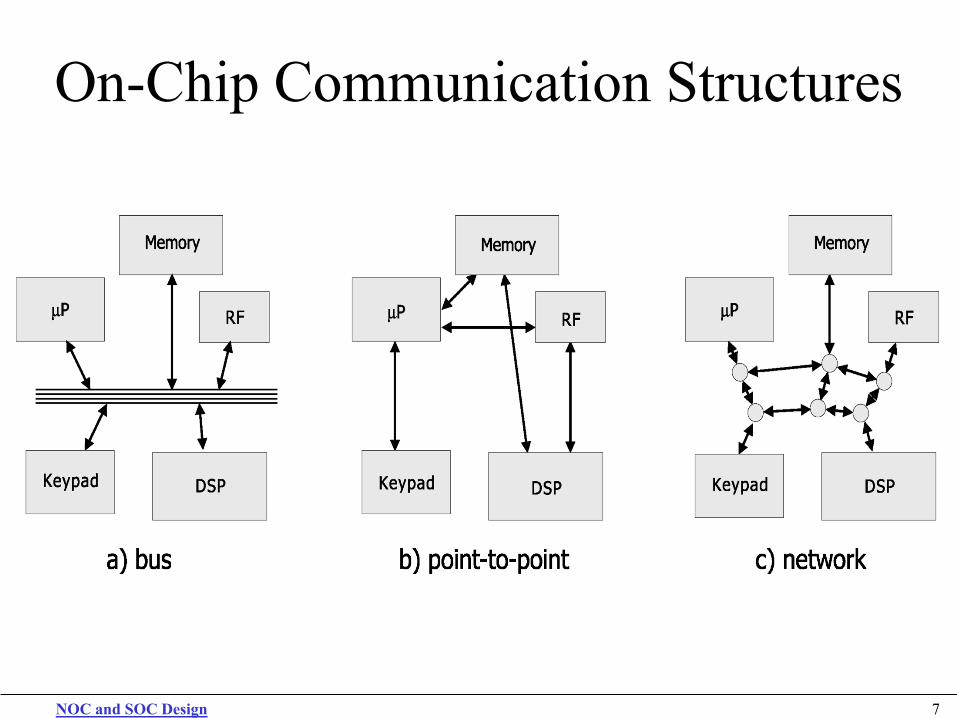
On-Chip Communication Structures
NOC and SOC Design 8
On-Chip Bus Interconnection
For highly connected multi-core system Communication bottleneck
For multi-master buses Arbitration will become a complex problem
Power grows for each communication event as more units attached will increase the capacitive load.
A crossbar switch can overcome some of these problems and limitations of the buses Crossbar is not scalable

NOC and SOC Design 9
SOC Communication Structures Dedicated Point-to-Point • Advantages
Optimal in terms of bandwidth, availability, latency and power usage Simple to design and verify as well as easier to model
• Disadvantages Number of links may increase exponentially with the increase in number of cores Hardware Area Routing Problems
NOC and SOC Design 10
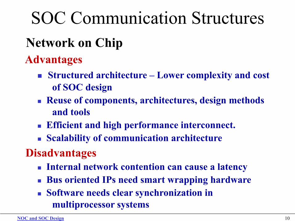
SOC Communication Structures Network on Chip Advantages
Structured architecture – Lower complexity and cost of SOC design Reuse of components, architectures, design methods and tools Efficient and high performance interconnect. Scalability of communication architecture
Disadvantages Internal network contention can cause a latency Bus oriented IPs need smart wrapping hardware Software needs clear synchronization in multiprocessor systems
NOC and SOC Design 11
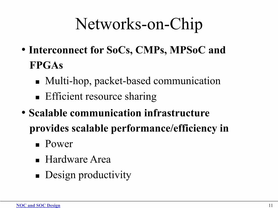
Networks-on-Chip • Interconnect for SoCs, CMPs, MPSoC and FPGAs
Multi-hop, packet-based communication Efficient resource sharing
• Scalable communication infrastructure provides scalable performance/efficiency in
Power Hardware Area Design productivity

NOC and SOC Design 12
Networks-on-Chip • Interconnect for SoCs, CMPs, MPSoC and FPGAs
Multi-hop, packet-based communication Efficient resource sharing
• Scalable communication infrastructure provides scalable performance/efficiency in
Power Hardware Area Design productivity
NOC and SOC Design 13
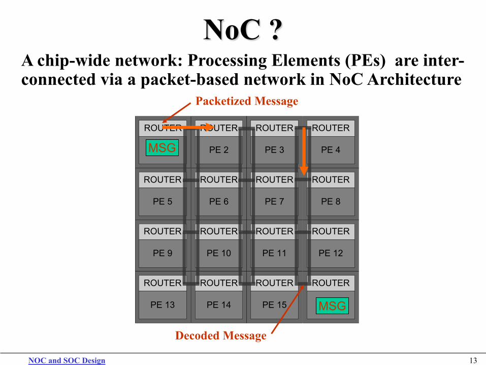
NoC ? A chip-wide network: Processing Elements (PEs) are inter-connected via a packet-based network in NoC Architecture
textROUTER
PE 1
textROUTER
PE 5
textROUTER
PE 9
textROUTER
PE 13
textROUTER
PE 2
textROUTER
PE 6
textROUTER
PE 10
textROUTER
PE 14
textROUTER
PE 3
textROUTER
PE 7
textROUTER
PE 11
textROUTER
PE 15
textROUTER
PE 4
textROUTER
PE 8
textROUTER
PE 12
textROUTER
PE 16
MSG
MSG
Packetized Message
Decoded Message
NOC and SOC Design 14
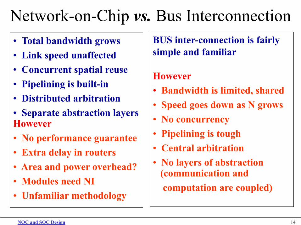
Network-on-Chip vs. Bus Interconnection • Total bandwidth grows • Link speed unaffected • Concurrent spatial reuse • Pipelining is built-in • Distributed arbitration • Separate abstraction layers However • No performance guarantee • Extra delay in routers • Area and power overhead? • Modules need NI • Unfamiliar methodology
BUS inter-connection is fairly simple and familiar However • Bandwidth is limited, shared • Speed goes down as N grows • No concurrency • Pipelining is tough • Central arbitration • No layers of abstraction (communication and computation are coupled)
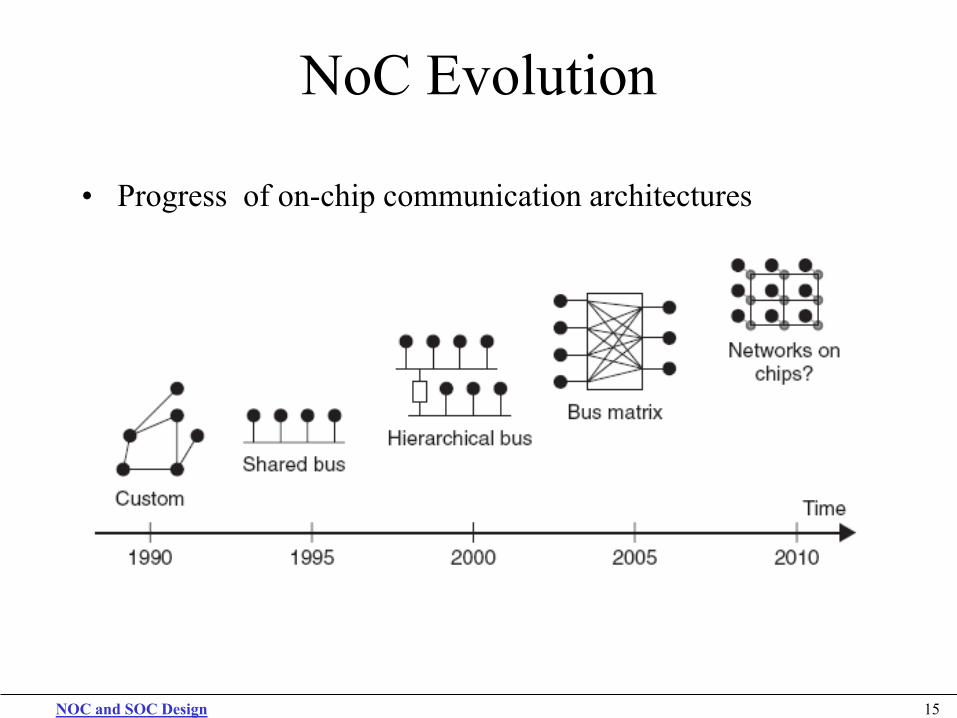
NoC Evolution
• Progress of on-chip communication architectures
NOC and SOC Design 15
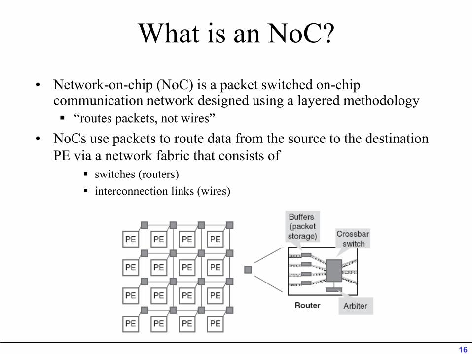
What is an NoC? • Network-on-chip (NoC) is a packet switched on-chip
communication network designed using a layered methodology “routes packets, not wires”
• NoCs use packets to route data from the source to the destination PE via a network fabric that consists of
switches (routers) interconnection links (wires)
16
NoC NoCs are an attempt to scale down the concepts of large-
scale networks, and apply them to the embedded system-on-chip (SoC) domain
NoC Properties Regular geometry that is scalable Flexible QoS guarantees Higher bandwidth Reusable components
• Buffers, arbiters, routers, protocol stack No long global wires (or global clock tree)
• No problematic global synchronization • GALS: Globally asynchronous, locally synchronous design
Reliable and predictable electrical and physical properties NOC and SOC Design 17
NOC and SOC Design 18
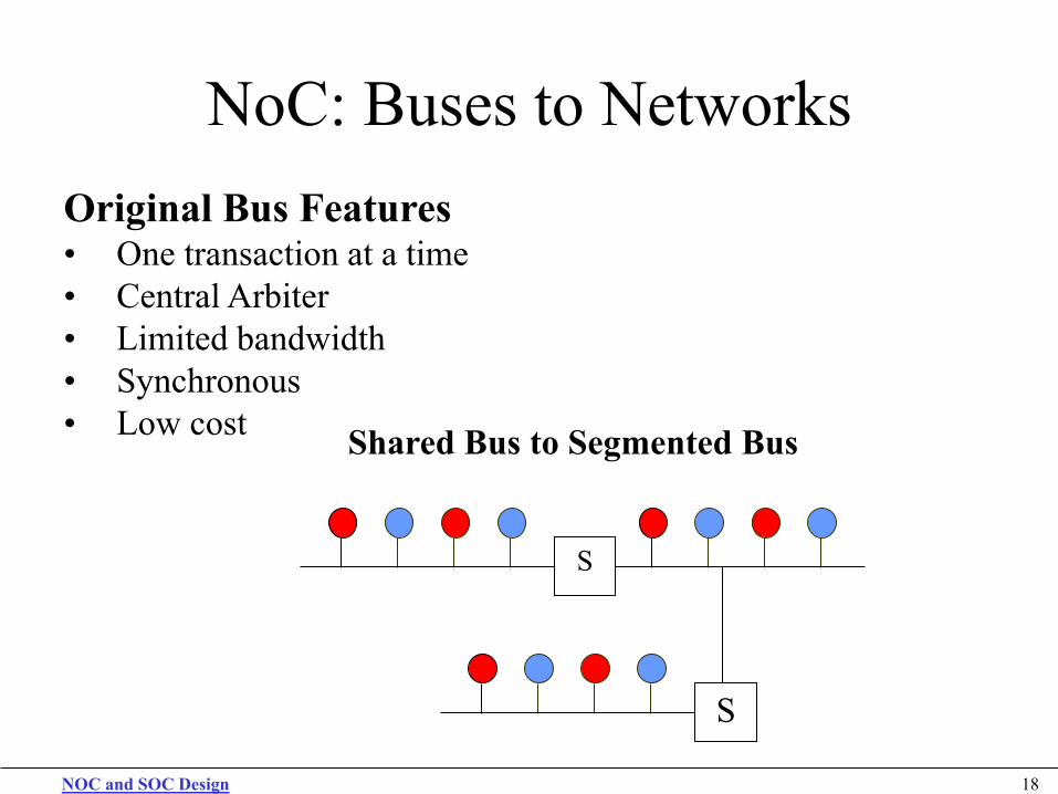
NoC: Buses to Networks Original Bus Features • One transaction at a time • Central Arbiter • Limited bandwidth • Synchronous • Low cost
S
S
Shared Bus to Segmented Bus
NOC and SOC Design 19
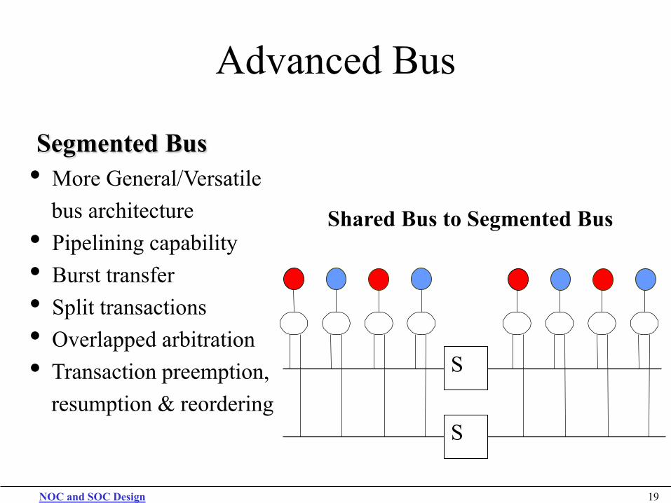
Advanced Bus
Segmented Bus • More General/Versatile bus architecture • Pipelining capability • Burst transfer • Split transactions • Overlapped arbitration • Transaction preemption, resumption & reordering
Shared Bus to Segmented Bus
S
S
NOC and SOC Design 20
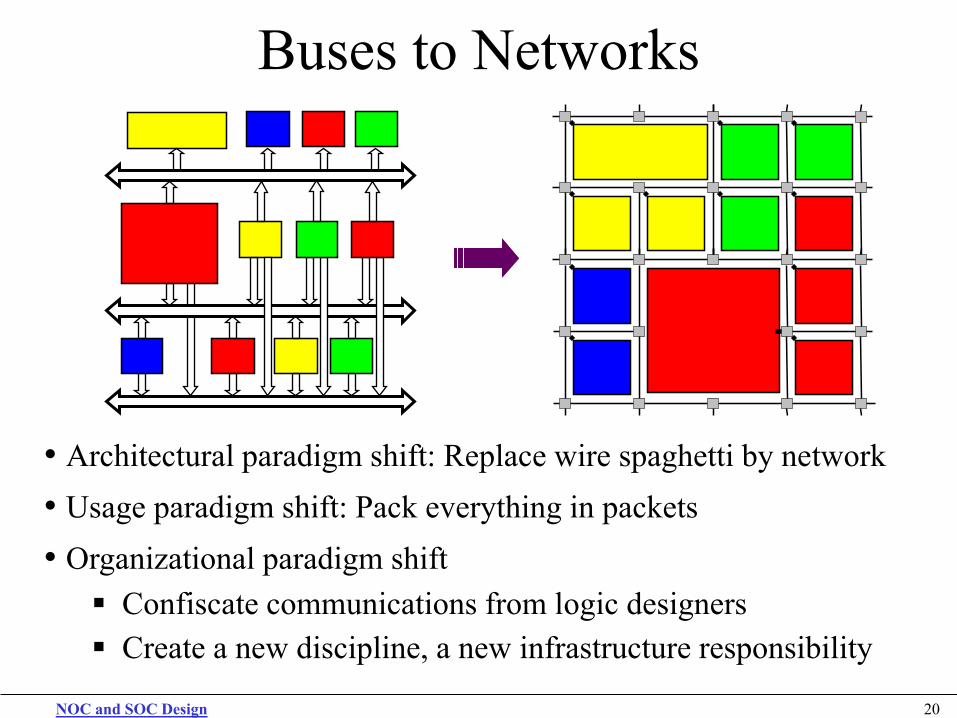
Buses to Networks
• Architectural paradigm shift: Replace wire spaghetti by network • Usage paradigm shift: Pack everything in packets • Organizational paradigm shift Confiscate communications from logic designers Create a new discipline, a new infrastructure responsibility
NOC and SOC Design 21
NoC Related Main Problems Global interconnect design problems:
• Delay • Power • Noise • Scalability • Reliability
System integration Productivity problem Chip Multi Processors For power-efficient computing
NOC and SOC Design 22
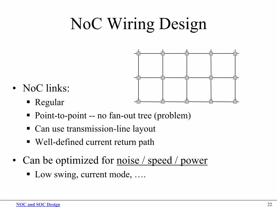
NoC Wiring Design
• NoC links: Regular Point-to-point -- no fan-out tree (problem) Can use transmission-line layout Well-defined current return path
• Can be optimized for noise / speed / power Low swing, current mode, ….
NOC and SOC Design 23
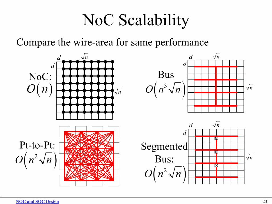
NoC Scalability Compare the wire-area for same performance
n
n
dd
n
n
dd
NoC:
n
n
dd
Bus
Segmented Bus:
Pt-to-Pt:
( )3O n n
( )2O n n
( )O n
( )2O n n
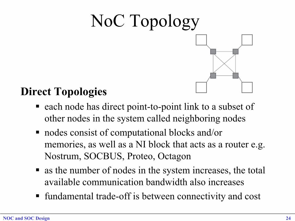
NoC Topology
Direct Topologies each node has direct point-to-point link to a subset of
other nodes in the system called neighboring nodes nodes consist of computational blocks and/or
memories, as well as a NI block that acts as a router e.g. Nostrum, SOCBUS, Proteo, Octagon
as the number of nodes in the system increases, the total available communication bandwidth also increases
fundamental trade-off is between connectivity and cost
NOC and SOC Design 24
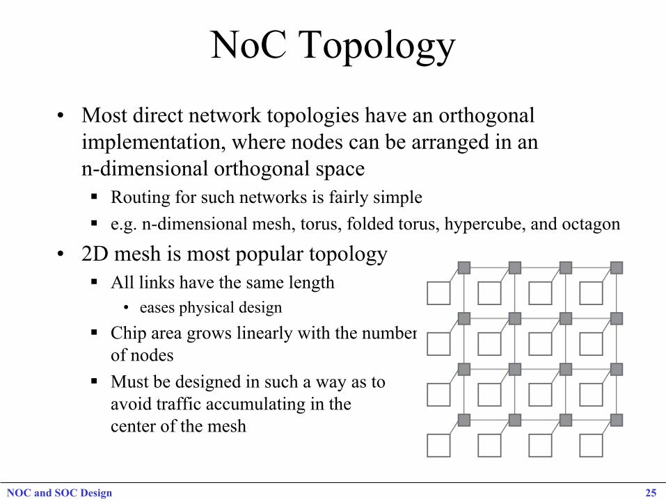
NoC Topology • Most direct network topologies have an orthogonal
implementation, where nodes can be arranged in an n-dimensional orthogonal space Routing for such networks is fairly simple e.g. n-dimensional mesh, torus, folded torus, hypercube, and octagon
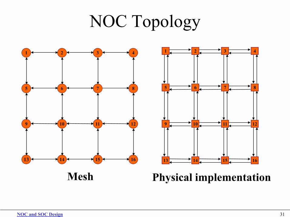
• 2D mesh is most popular topology All links have the same length
• eases physical design Chip area grows linearly with the number
of nodes Must be designed in such a way as to
avoid traffic accumulating in the center of the mesh
NOC and SOC Design 25
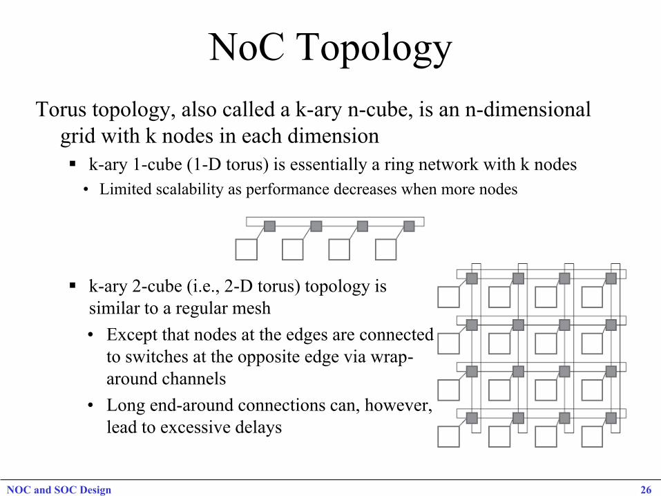
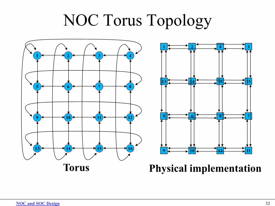
NoC Topology Torus topology, also called a k-ary n-cube, is an n-dimensional
grid with k nodes in each dimension k-ary 1-cube (1-D torus) is essentially a ring network with k nodes • Limited scalability as performance decreases when more nodes
k-ary 2-cube (i.e., 2-D torus) topology is similar to a regular mesh • Except that nodes at the edges are connected
to switches at the opposite edge via wrap- around channels
• Long end-around connections can, however, lead to excessive delays
NOC and SOC Design 26
NoC Topology
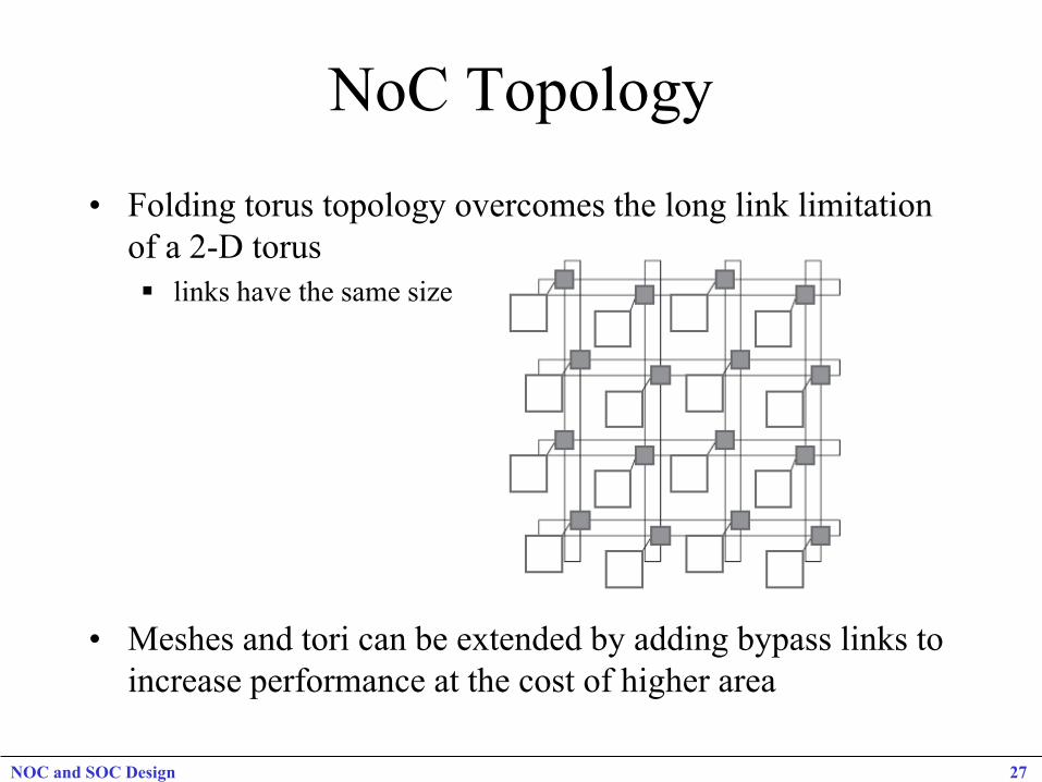
• Folding torus topology overcomes the long link limitation of a 2-D torus links have the same size
• Meshes and tori can be extended by adding bypass links to
increase performance at the cost of higher area
NOC and SOC Design 27
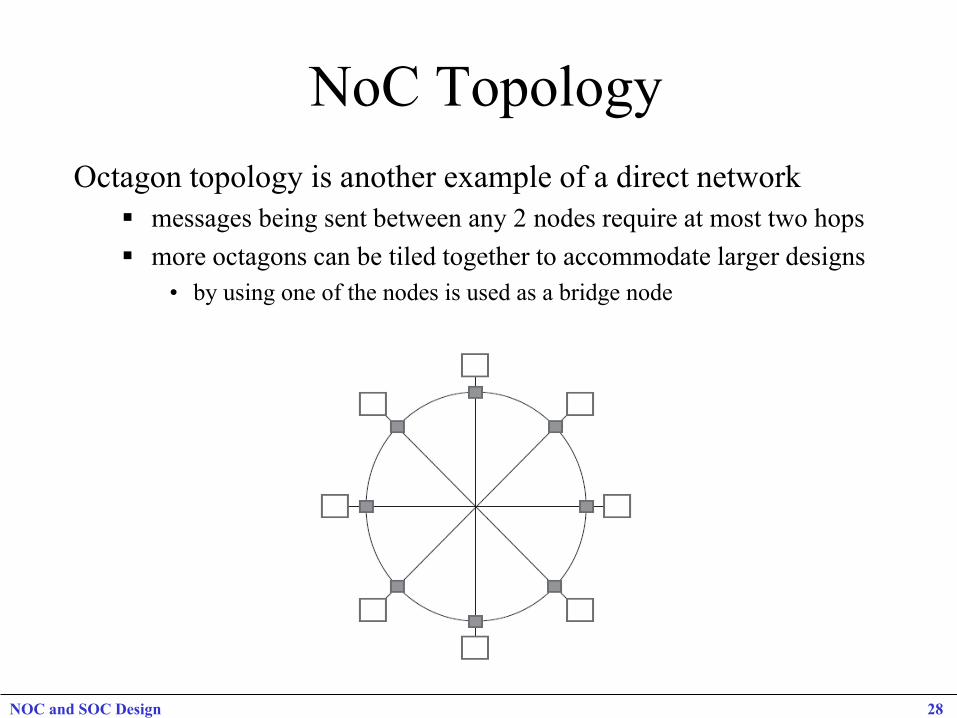
NoC Topology Octagon topology is another example of a direct network
messages being sent between any 2 nodes require at most two hops more octagons can be tiled together to accommodate larger designs
• by using one of the nodes is used as a bridge node
NOC and SOC Design 28
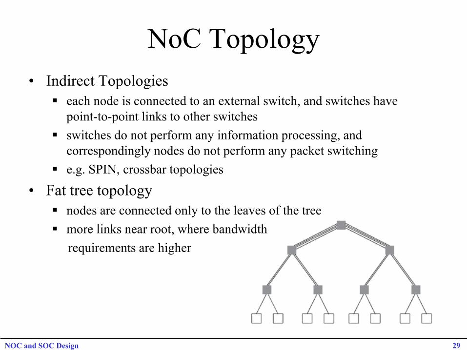
NoC Topology • Indirect Topologies
each node is connected to an external switch, and switches have point-to-point links to other switches
switches do not perform any information processing, and correspondingly nodes do not perform any packet switching
e.g. SPIN, crossbar topologies
• Fat tree topology nodes are connected only to the leaves of the tree more links near root, where bandwidth requirements are higher
NOC and SOC Design 29
NOC and SOC Design 30
Irregular NoC Topologies
• Based on the concept of using only what is necessary.
• Application-specific topologies.
• Eliminate unneeded resources and bandwidth from the system.
• Leads to reduced power and area use.
• Requires additional design work.
NOC and SOC Design 31
NOC Topology 1 2 3 4
5 6 7 8
9 10 11 12
13 14 15 16
1 2 3 4
5 6 7 8
9 10 11 12
13 14 15 16
Mesh Physical implementation
NOC and SOC Design 32
NOC Torus Topology
Torus Physical implementation
1 2 4 3
13 14 16 15
5 6 8 7
9 10 12 11
1 2 3 4
5 6 7 8
9 10 11 12
13 14 15 16
Deadlock, Livelock, and Starvation
Deadlock: A packet does not reach its destination, because it is blocked at some intermediate resource. Livelock: A packet does not reach its destination, because it enters a cyclic path. Starvation: A packet does not reach its destination, because some resource does not grant access (while it grants access to other packets).
NOC and SOC Design 33
NOC and SOC Design 34
Definitions and Terminology
Switch: The component of the network that is in charge of flit routing.
Flit Latency: The time needed for a FLIT to reach its target PE from its source PE.
Packet Latency: The time needed for a PACKET to reach its target PE from its source PE.
Packet Spread: The time from the reception of the first flit of a packet to the reception of the last one.
NOC and SOC Design 35
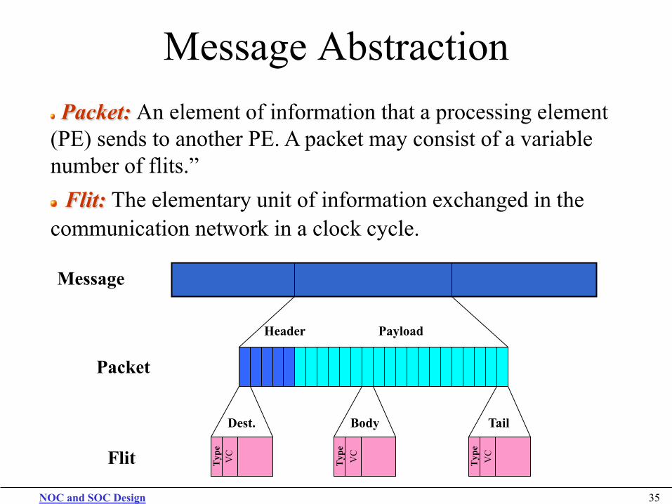
Message Abstraction
Message
Packet
Header Payload
Flit Typ
e
Dest.
VC
Typ
e
Body
VC
Typ
e
Tail
VC
Packet: An element of information that a processing element (PE) sends to another PE. A packet may consist of a variable number of flits.” Flit: The elementary unit of information exchanged in the
communication network in a clock cycle.
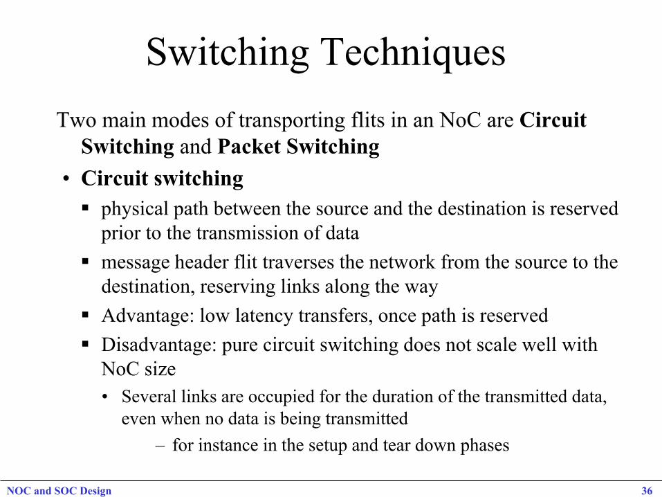
Switching Techniques Two main modes of transporting flits in an NoC are Circuit
Switching and Packet Switching • Circuit switching physical path between the source and the destination is reserved
prior to the transmission of data message header flit traverses the network from the source to the
destination, reserving links along the way Advantage: low latency transfers, once path is reserved Disadvantage: pure circuit switching does not scale well with
NoC size • Several links are occupied for the duration of the transmitted data,
even when no data is being transmitted – for instance in the setup and tear down phases
NOC and SOC Design 36
Switching Strategies Virtual Circuit Switching creates virtual circuits that are multiplexed on links number of virtual links (or virtual channels (VCs)) that can be
supported by a physical link depends on buffers allocated to link Possible to allocate either one buffer per virtual link or one buffer
per physical link Allocating one buffer per virtual link • depends on how virtual circuits are spatially distributed in the
NoC, routers can have a different number of buffers • can be expensive due to the large number of shared buffers • multiplexing virtual circuits on a single link also requires
scheduling at each router and link (end-to-end schedule) • conflicts between different schedules can make it difficult to
achieve bandwidth and latency guarantees
NOC and SOC Design 37
Switching Strategies, cont. Virtual Circuit Switching Allocating one buffer per physical link
o virtual circuits are time multiplexed with a single buffer per link
o uses time division multiplexing (TDM) to statically schedule the usage of links among virtual circuits
o flits are typically buffered at the NIs and sent into the NoC according to the TDM schedule
o global scheduling with TDM makes it easier to achieve end-to-end bandwidth and latency guarantees
o less expensive router implementation, with fewer buffers
NOC and SOC Design 38

Packet Switching packets are transmitted from source and make their way
independently to receiver • Possibly along different routes and with different delays
zero start up time, followed by a variable delay due to contention in routers along packet path
QoS guarantees are harder to make in packet switching than in circuit switching
three main packet switching scheme variants SAF (Store and Forward) Switching
packet is sent from one router to the next only if the receiving router has buffer space for entire packet
buffer size in the router is at least equal to the size of a packet Disadvantage: excessive buffer requirements
NOC and SOC Design 39
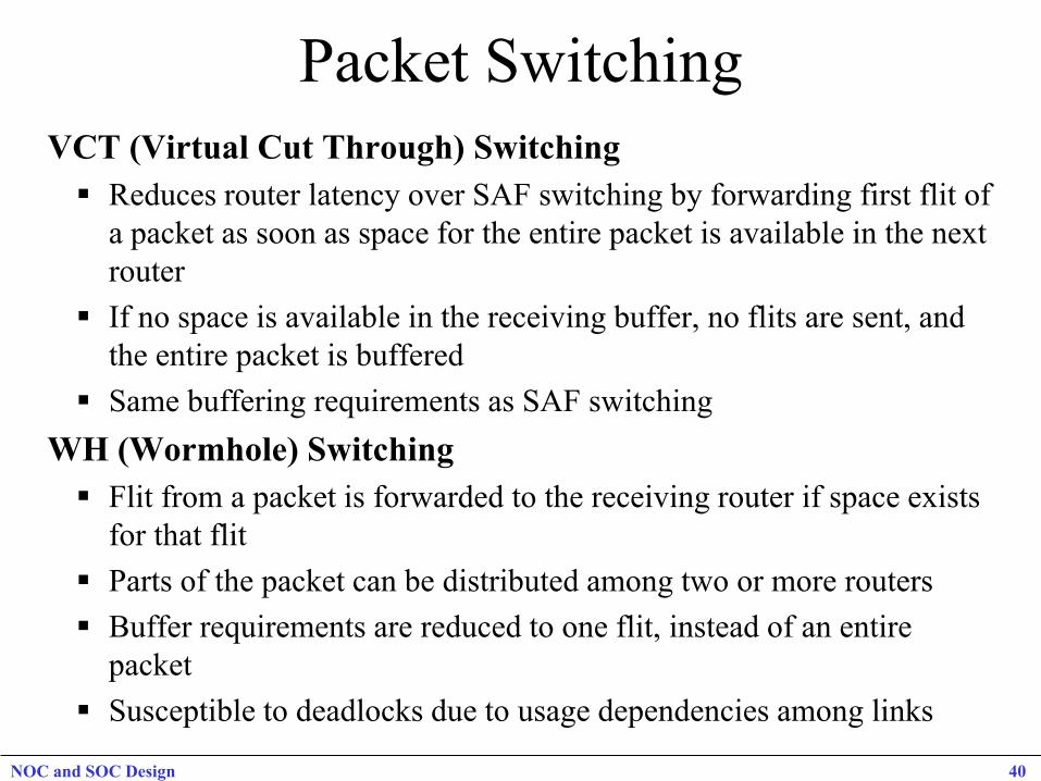
Packet Switching VCT (Virtual Cut Through) Switching Reduces router latency over SAF switching by forwarding first flit of
a packet as soon as space for the entire packet is available in the next router
If no space is available in the receiving buffer, no flits are sent, and the entire packet is buffered
Same buffering requirements as SAF switching WH (Wormhole) Switching Flit from a packet is forwarded to the receiving router if space exists
for that flit Parts of the packet can be distributed among two or more routers Buffer requirements are reduced to one flit, instead of an entire
packet Susceptible to deadlocks due to usage dependencies among links
NOC and SOC Design 40
Routing Algorithms • Responsible for correctly and efficiently routing packets or
circuits from the source to the destination • Choice of a routing algorithm depends on trade-offs between
several potentially conflicting metrics Minimizing power required for routing Minimizing logic & routing tables to achieve lower area footprint increasing performance by reducing delay and maximizing traffic
utilization of the network improving robustness to better adapt to changing traffic needs
• Routing schemes can be classified into several categories Static or dynamic routing Distributed or source routing Minimal or non-minimal routing
NOC and SOC Design 41
Routing Algorithms Static and Dynamic routing Static Routing: fixed paths are used to transfer data between a
particular source and destination • does not take into account current state of the network
Advantages of static routing: • easy to implement, since very little additional router logic is required • in-order packet delivery if single path is used
Dynamic Routing: routing decisions are made according to the current state of the network • considering factors such as availability and load on links
Path between source and destination may change over time • as traffic conditions and requirements of the application change
More resources needed to monitor state of the network and dynamically change routing paths
Able to better distribute traffic in a network NOC and SOC Design 42
Routing Algorithms Distributed and Source Routing Static and dynamic routing schemes can be further classified
depending on where the routing information is stored, and where routing decisions are made
Distributed routing: each packet carries the destination address • e.g., XY co-ordinates or number identifying destination node/router • Routing decisions are made in each router by looking up the destination
addresses in a routing table or by executing a hardware function Source routing: packet carries routing information • Pre-computed routing tables are stored at a nodes’ NI • Routing information is looked up at the source NI and routing information
is added to the header of the packet (increasing packet size) • When a packet arrives at a router, the routing information is extracted
from the routing field in the packet header • Does not require a destination address in a packet, any intermediate
routing tables, or functions needed to calculate the route NOC and SOC Design 43
Routing algorithms Minimal and Non-minimal routing minimal routing: length of the routing path from the source to the
destination is the shortest possible length between the two nodes • e.g. in a mesh NoC topology (where each node can be identified by its
XY co-ordinates in the grid) if source node is at (0, 0) and destination node is at (i, j), then the minimal path length is |i| + |j|
• source does not start sending a packet if minimal path is not available Non-minimal routing: can use longer paths if a minimal path is not
available. • by allowing non-minimal paths, the number of alternative paths
is increased, which can be useful for avoiding congestion • disadvantage: overhead of additional power consumption
NOC and SOC Design 44
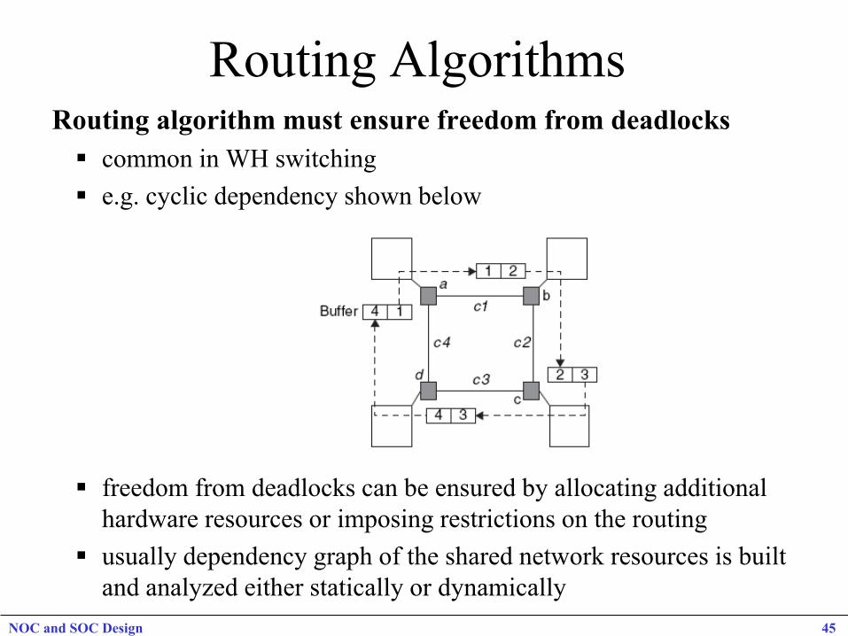
Routing Algorithms Routing algorithm must ensure freedom from deadlocks common in WH switching e.g. cyclic dependency shown below
freedom from deadlocks can be ensured by allocating additional hardware resources or imposing restrictions on the routing
usually dependency graph of the shared network resources is built and analyzed either statically or dynamically
NOC and SOC Design 45
Routing Algorithms Routing Algorithm must ensure freedom from Livelocks Livelocks are similar to deadlocks, except that states of the resources
involved constantly change with regard to one another, without making any progress • occurs especially when dynamic (adaptive) routing is used • e.g. can occur in a deflective “hot potato” routing if a packet is bounced
around over and over again between routers and never reaches its destination
Livelocks can be avoided with simple priority rules
Routing Algorithm must ensure freedom from starvation under scenarios where certain packets are prioritized during routing,
some of the low priority packets never reach their intended destination
can be avoided by using a fair routing algorithm, or reserving some bandwidth for low priority data packets
NOC and SOC Design 46

Flow Control Schemes • Goal of flow control is to allocate network resources for packets
traversing a NoC can also be viewed as a problem of resolving contention during packet
traversal
• At the data link-layer level, when transmission errors occur, recovery from the error depends on the support provided by the flow control mechanism e.g. if a corrupted packet needs to be retransmitted, flow of packets from
the sender must be stopped, and request signaling must be performed to reallocate buffer and bandwidth resources
• Most flow control techniques can manage link congestion • But not all schemes can (by themselves) reallocate all the
resources required for retransmission when errors occur either error correction or a scheme to handle reliable transfers must be
implemented at a higher layer NOC and SOC Design 47
Flow Control Schemes
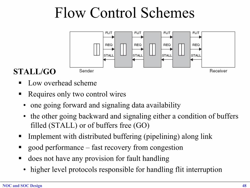
STALL/GO Low overhead scheme Requires only two control wires • one going forward and signaling data availability • the other going backward and signaling either a condition of buffers
filled (STALL) or of buffers free (GO) Implement with distributed buffering (pipelining) along link good performance – fast recovery from congestion does not have any provision for fault handling • higher level protocols responsible for handling flit interruption
NOC and SOC Design 48
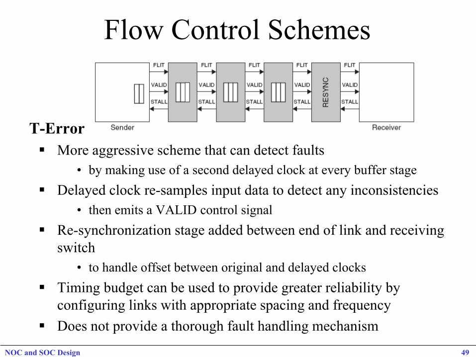
Flow Control Schemes
T-Error More aggressive scheme that can detect faults
• by making use of a second delayed clock at every buffer stage Delayed clock re-samples input data to detect any inconsistencies
• then emits a VALID control signal Re-synchronization stage added between end of link and receiving
switch • to handle offset between original and delayed clocks
Timing budget can be used to provide greater reliability by configuring links with appropriate spacing and frequency
Does not provide a thorough fault handling mechanism
NOC and SOC Design 49
Flow Control Schemes
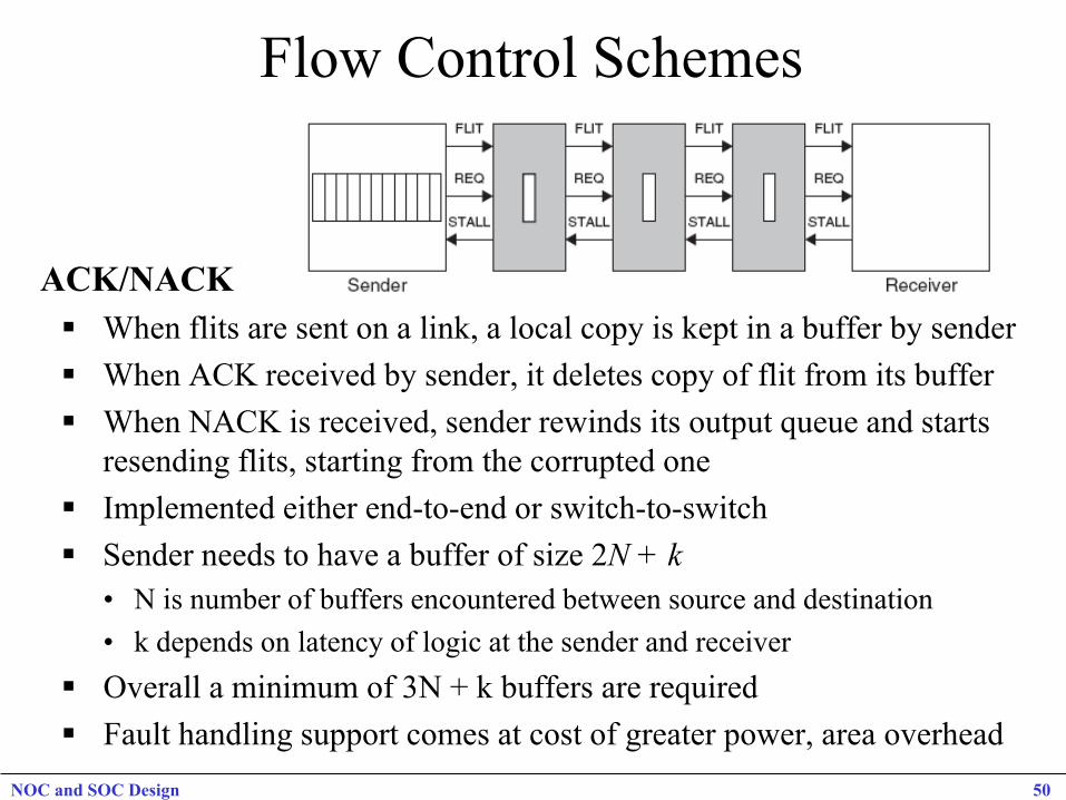
ACK/NACK When flits are sent on a link, a local copy is kept in a buffer by sender When ACK received by sender, it deletes copy of flit from its buffer When NACK is received, sender rewinds its output queue and starts
resending flits, starting from the corrupted one Implemented either end-to-end or switch-to-switch Sender needs to have a buffer of size 2N + k
• N is number of buffers encountered between source and destination • k depends on latency of logic at the sender and receiver
Overall a minimum of 3N + k buffers are required Fault handling support comes at cost of greater power, area overhead
NOC and SOC Design 50
Flow Control Schemes Network and Transport-Layer Flow Control Flow Control without Resource Reservation
• Technique #1: drop packets when receiver NI full – improves congestion in short term but increases it in long term
• Technique #2: return packets that do not fit into receiver buffers to sender – to avoid deadlock, rejected packets must be accepted by sender
• Technique #3: deflection routing – when packet cannot be accepted at receiver, it is sent back into network – packet does not go back to sender, but keeps hopping from router to router till
it is accepted at receiver
Flow Control with Resource Reservation • credit-based flow control with resource reservation • credit counter at sender NI tracks free space available in receiver NI
buffers • credit packets can piggyback on response packets • end-to-end or link-to-link
NOC and SOC Design 51
NOC and SOC Design 52
Switching Techniques
Packet Switching – Routing Protocols Store and Forward: Router cost is packet based. Packet size also affects latency and buffering requirements. Stalling happens at two nodes and the link between them.
Wormhole: Router cost is based on header. Header can effect latency and buffering at the router is based on the header size. Stalling can happen at all the nodes and links spanned by the packet..
Virtual Cut-through: Router cost depends on header and packet size. Stalling at local nodes level.
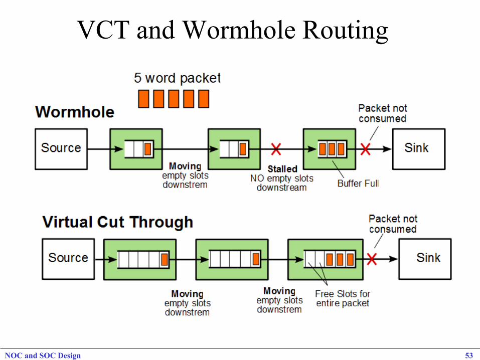
VCT and Wormhole Routing
NOC and SOC Design 53
NOC and SOC Design 54
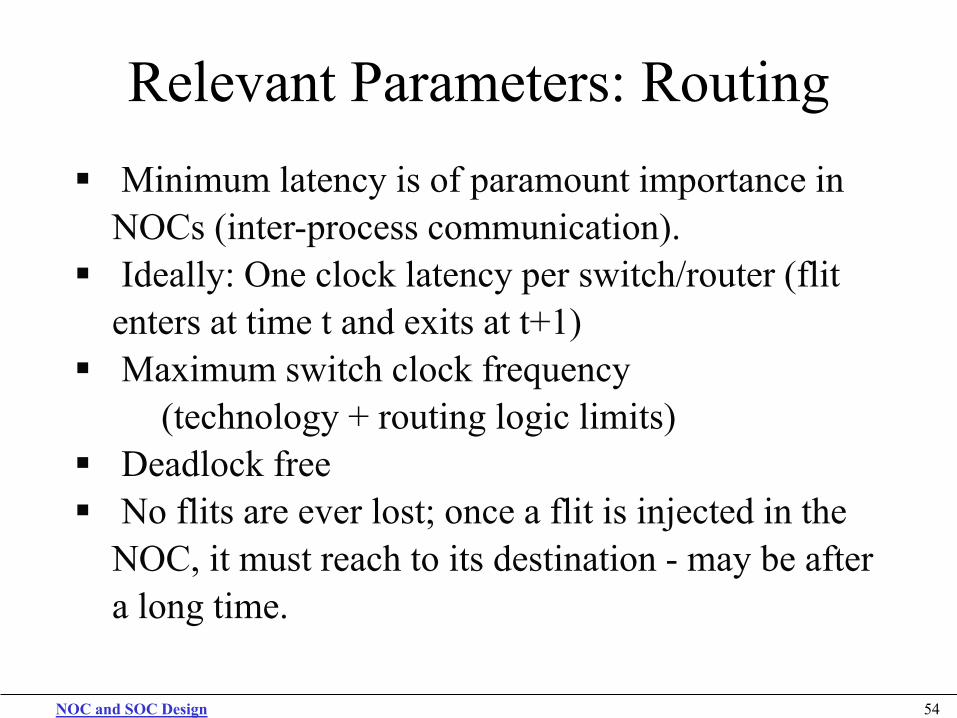
Relevant Parameters: Routing Minimum latency is of paramount importance in
NOCs (inter-process communication). Ideally: One clock latency per switch/router (flit
enters at time t and exits at t+1) Maximum switch clock frequency
(technology + routing logic limits) Deadlock free No flits are ever lost; once a flit is injected in the
NOC, it must reach to its destination - may be after a long time.

NOC and SOC Design 55
Fixed Shortest Path Routing
Suitable for Regular Topologies e.g. Mesh, Torus, Tree, etc. X-Y routing (fist x then y direction. Simple Router No deadlock scenario No retransmission No reordering of messages Power-efficient
NOC and SOC Design 56
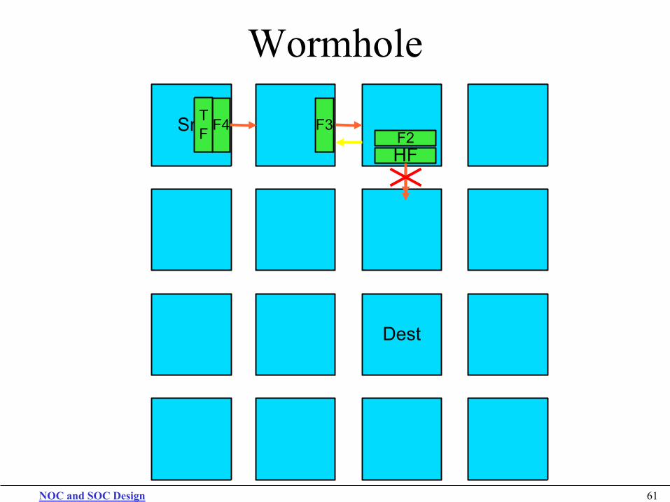
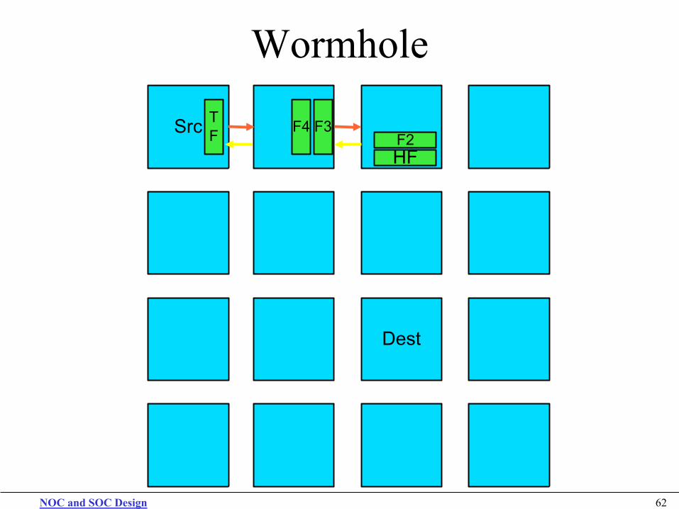
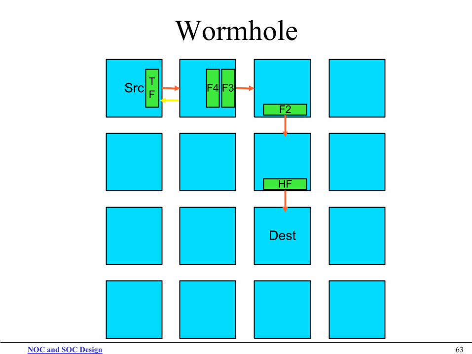
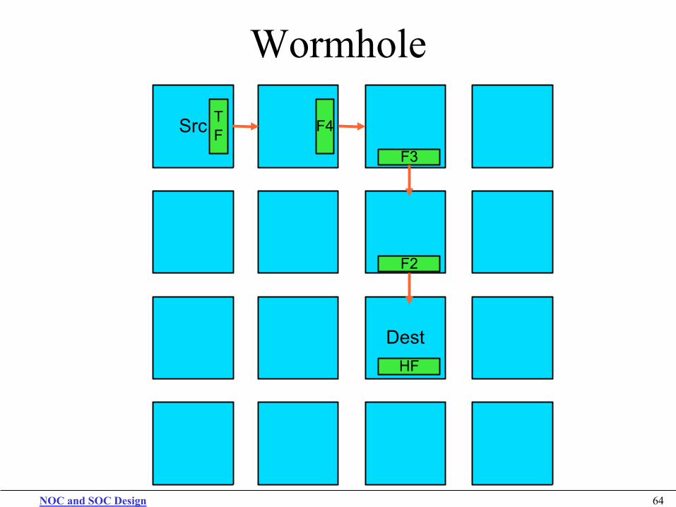
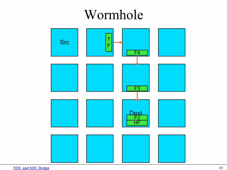
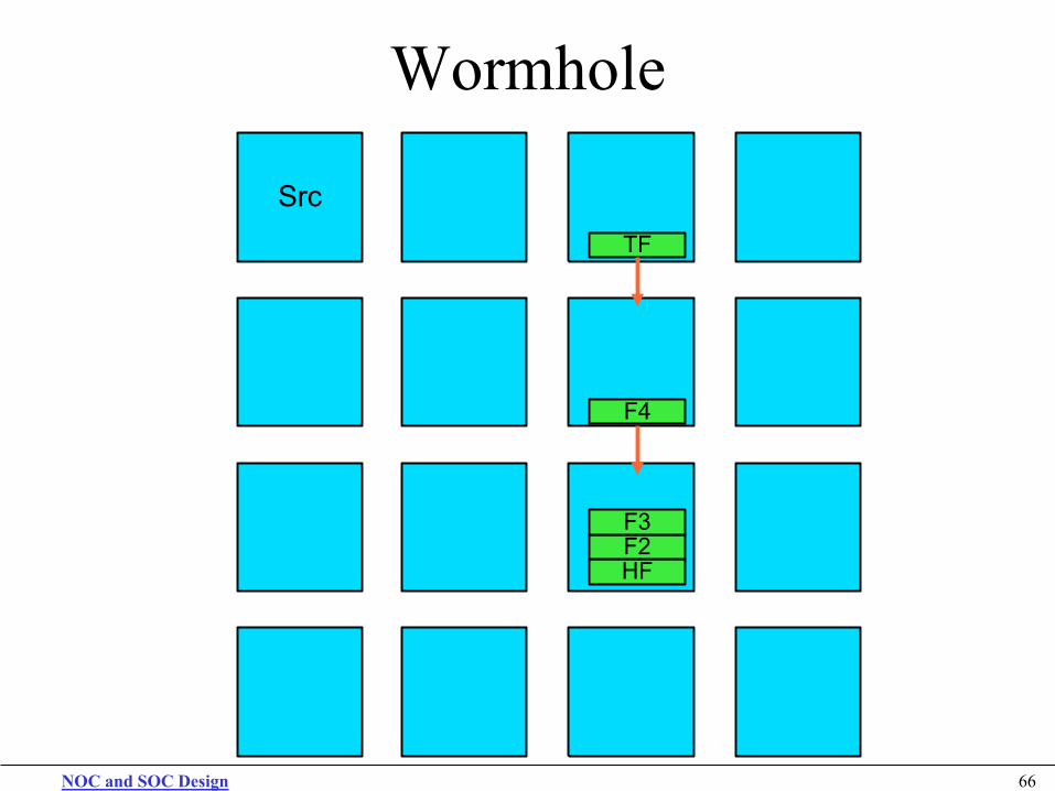
Wormhole Routing
In wormhole routing a header flit “digs” the path and hold. Successive flits are routed to the same path or direction In case of blocks and loss-less NoC we need: Buffers A back-pressure mechanism if we don’t have
infinite size FIFOs…
NOC and SOC Design 57
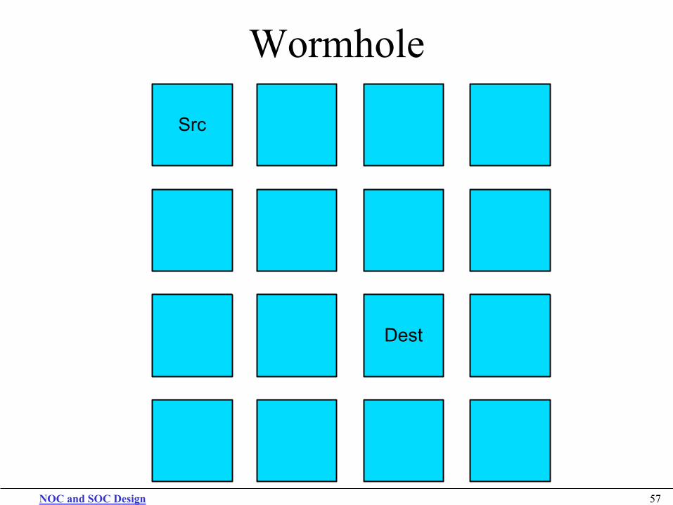
Wormhole
Src
Dest

NOC and SOC Design 58
Wormhole
Src
Dest
HF
F2 F3 F4 TF
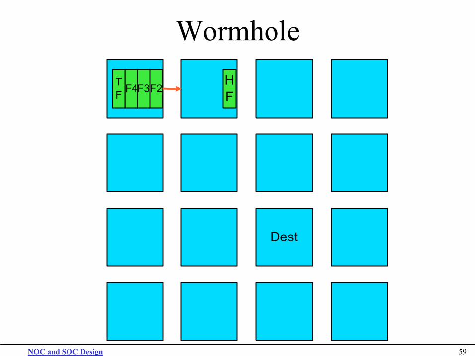
NOC and SOC Design 59
Wormhole
Src
Dest
F2 HF
F3 F4 TF
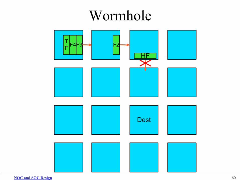
NOC and SOC Design 60
Wormhole
Src
Dest
F3 F2
HF
F4 TF
NOC and SOC Design 61
Wormhole
Src
Dest
F4 F3 F2 HF
TF
NOC and SOC Design 62
Wormhole
Src
Dest
F4 F3 F2 HF
TF
NOC and SOC Design 63
Wormhole
Src
Dest
F3
F2
HF
F4 TF
NOC and SOC Design 64
Wormhole
Src
Dest
F3
F2
F4 TF
HF
NOC and SOC Design 65
Wormhole
Src
Dest
F4
F3
TF
HF F2
NOC and SOC Design 66
Wormhole
Src
Dest
TF
F4
HF F2 F3
NOC and SOC Design 67
Wormhole
Src
Dest
TF
HF F2 F3 F4
NOC and SOC Design 68
Wormhole
Src
Dest HF F2 F3
TF F4
NOC and SOC Design 69
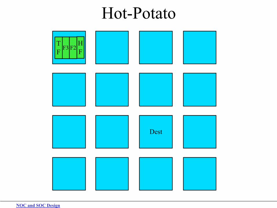
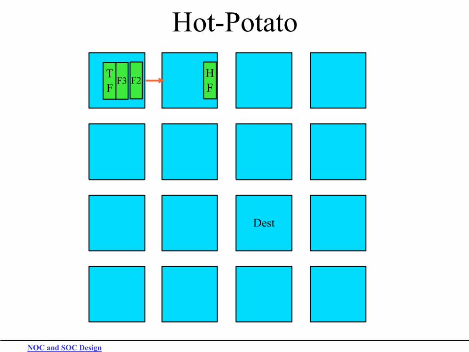
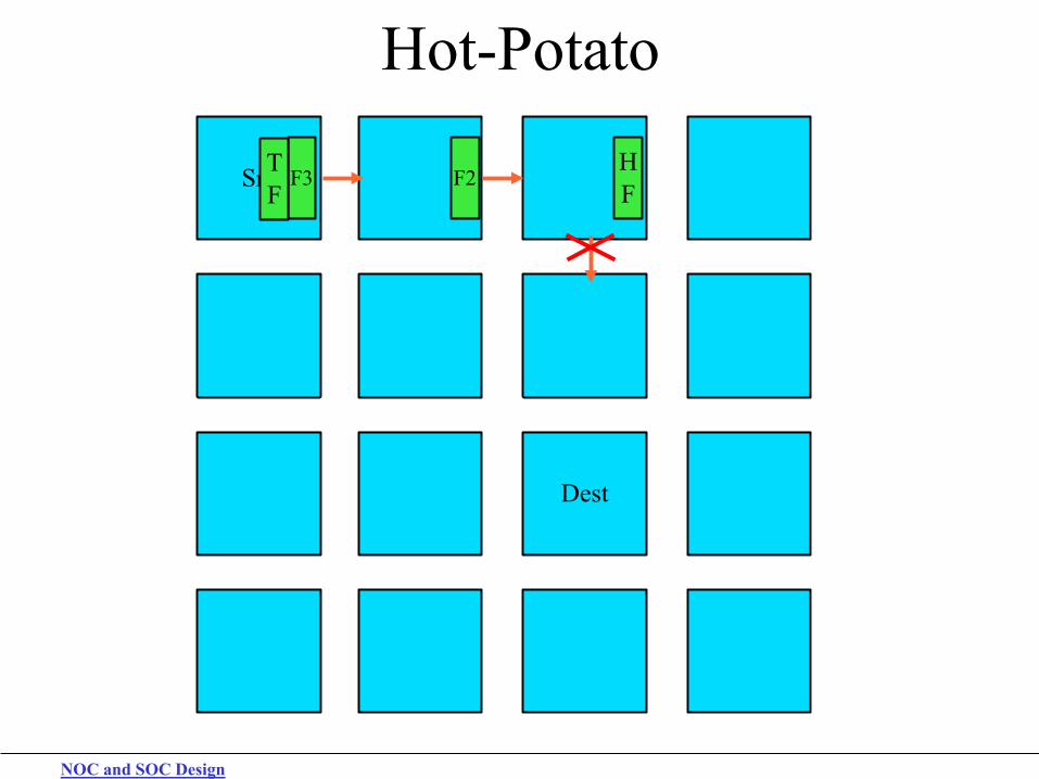
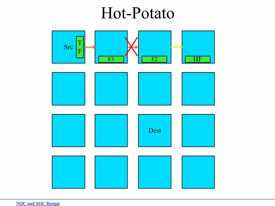
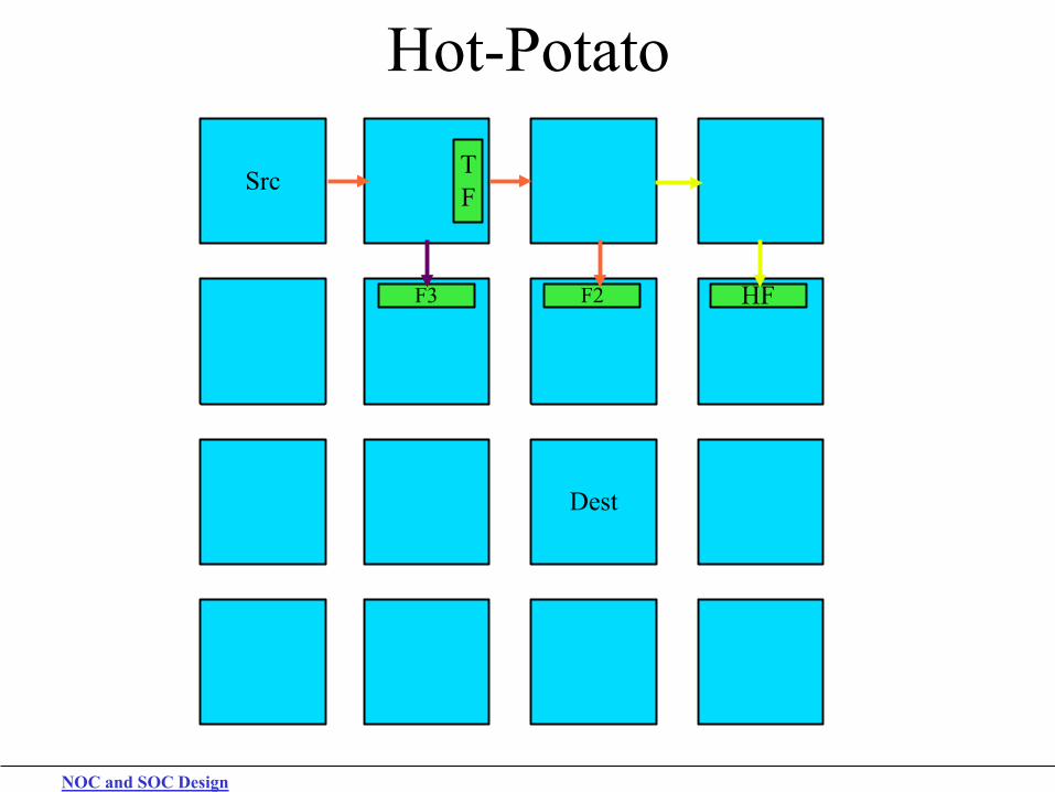
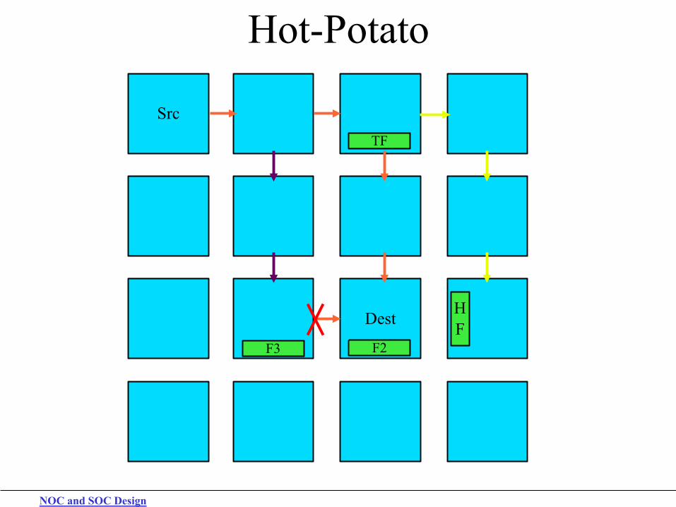
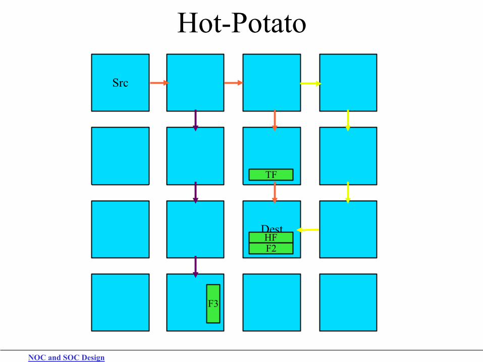
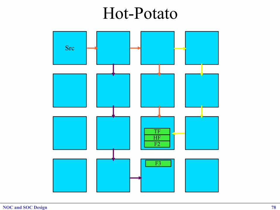
Deflection Routing Hot Potato – Deadlock Free Routing Every flit can be routed to different directions (no packet notion at the switch level)
If the optimal direction is blocked, the flit is “deflected” to another direction
Switch latency of 1 clock cycle whatever the level of congestion Minimum buffer requirements
Packets reordering Adaptive routing No buffering No back pressure Works with Torus/Mesh
Wormhole Routing No packets reordering Static routing Buffering ( ≥ 2 flits/port) Back pressure XY routing needs mesh
Hot-Potato
Src
Dest
NOC and SOC Design 70
NOC and SOC Design
Hot-Potato
Src
Dest
HF F2 F3
TF
NOC and SOC Design
Hot-Potato
Src
Dest
F2 HF F3
TF
NOC and SOC Design
Hot-Potato
Src
Dest
F3 F2 HF
TF
NOC and SOC Design
Hot-Potato
Src
Dest
TF
HF F2 F3
NOC and SOC Design
Hot-Potato
Src
Dest
TF
HF F2 F3
NOC and SOC Design
Hot-Potato
Src
Dest
F3
TF
HF
F2
NOC and SOC Design
Hot-Potato
Src
Dest
TF
F3
F2 HF
Hot-Potato
Src
Dest
F3
F2 HF TF
NOC and SOC Design 78
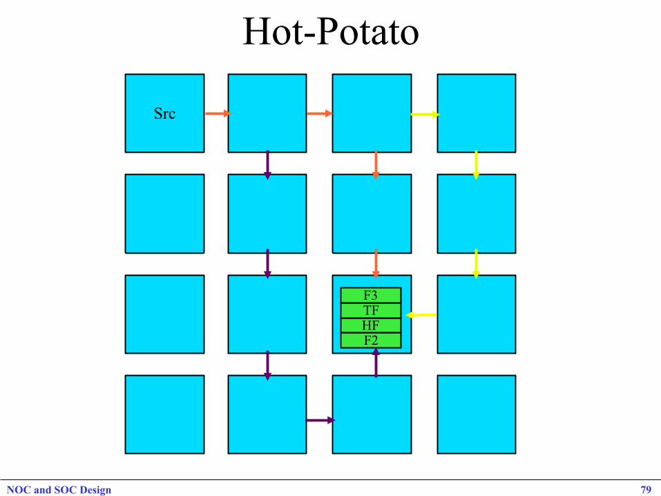
Hot-Potato
Src
Dest F2 HF TF F3
NOC and SOC Design 79
NOC and SOC Design 80
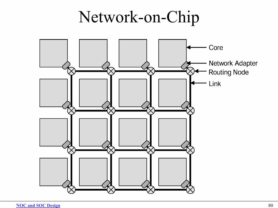
Network-on-Chip
NOC and SOC Design 81
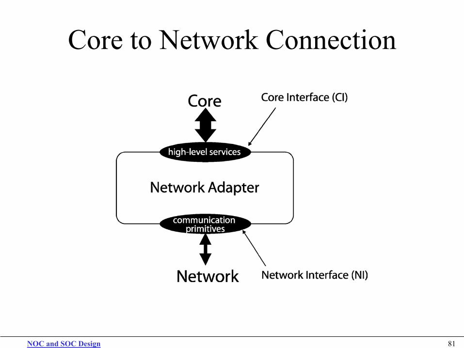
Core to Network Connection
NOC and SOC Design 82
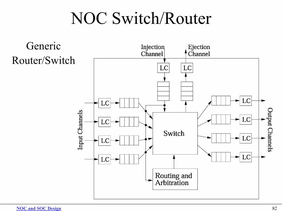
NOC Switch/Router Generic
Router/Switch
NOC and SOC Design 83
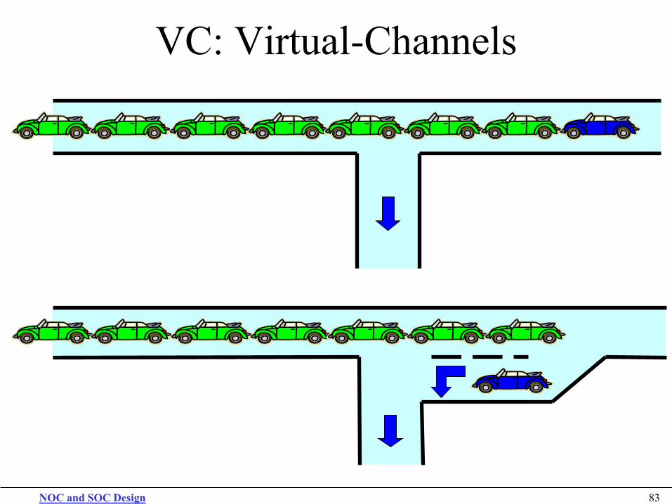
VC: Virtual-Channels
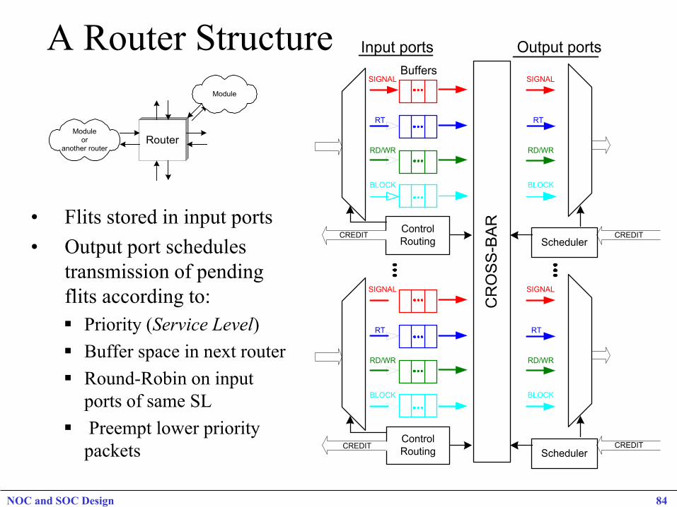
A Router Structure
• Flits stored in input ports • Output port schedules
transmission of pending flits according to: Priority (Service Level) Buffer space in next router Round-Robin on input
ports of same SL Preempt lower priority
packets
Router
Module
Moduleor
another router
CR
OS
S-B
AR
SchedulerControlRouting
CREDIT
BuffersSIGNAL
RT
RD/WR
BLOCK
SIGNAL
RT
RD/WR
BLOCK
CREDIT
SchedulerControlRouting
CREDIT
SIGNAL
RT
RD/WR
BLOCK
SIGNAL
RT
RD/WR
BLOCK
CREDIT
Output portsInput ports
NOC and SOC Design 84
Virtual Channel 2D Router VCID
From West (W)
From PE
Path SetSmartDemux
Arbiter (VA/SA)
Pre-selection Function (Congestion-Look-Ahead)
Pre-selection enable signals
Flit_inCredit_out
Output VC Resv_State
W_NE
S_NE
(Direction Vector)
Eject
For North-East (NE)
For South- East (SE)
PE_NE
N_SE
W_SE
PE_SE Mux
Credit, Status of Pending Msg Queues
*DecomposedCrossbar
(4x4)
N
S
E
W
Scheduling
For NE
For SE
For SW
For NW
N E S W
NOC and SOC Design 85
NOC and SOC Design 86
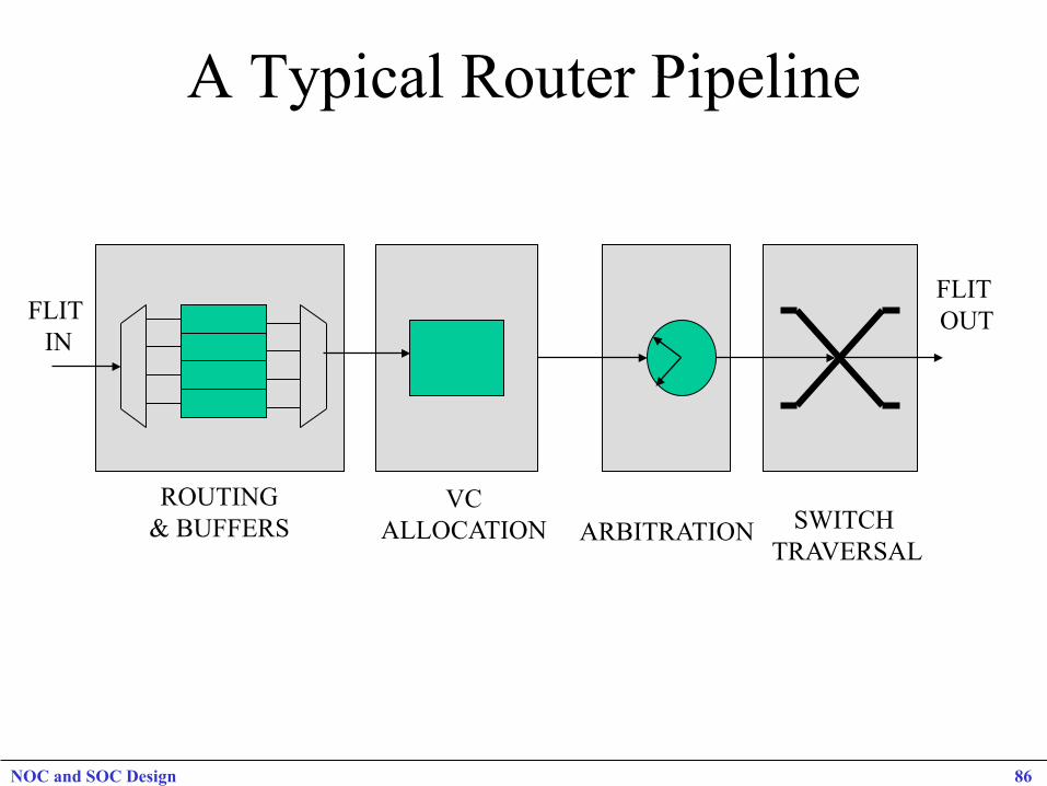
A Typical Router Pipeline
ROUTING & BUFFERS
VC ALLOCATION ARBITRATION SWITCH
TRAVERSAL
FLIT IN
FLIT OUT
NOC and SOC Design 87
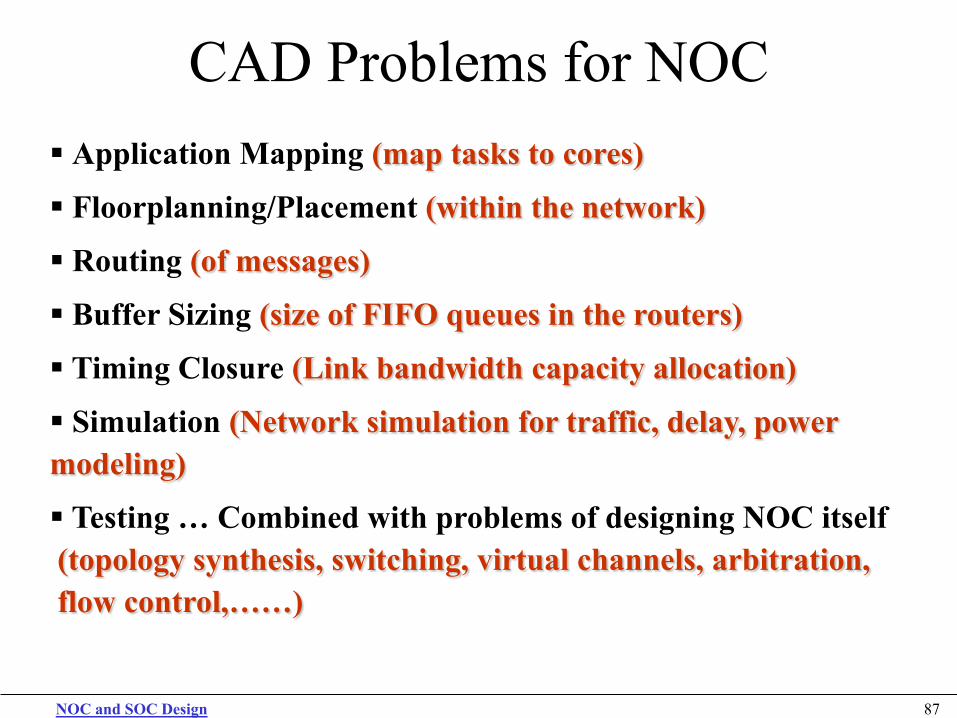
CAD Problems for NOC Application Mapping (map tasks to cores)
Floorplanning/Placement (within the network)
Routing (of messages)
Buffer Sizing (size of FIFO queues in the routers)
Timing Closure (Link bandwidth capacity allocation)
Simulation (Network simulation for traffic, delay, power modeling)
Testing … Combined with problems of designing NOC itself (topology synthesis, switching, virtual channels, arbitration, flow control,……)
NOC and SOC Design 88
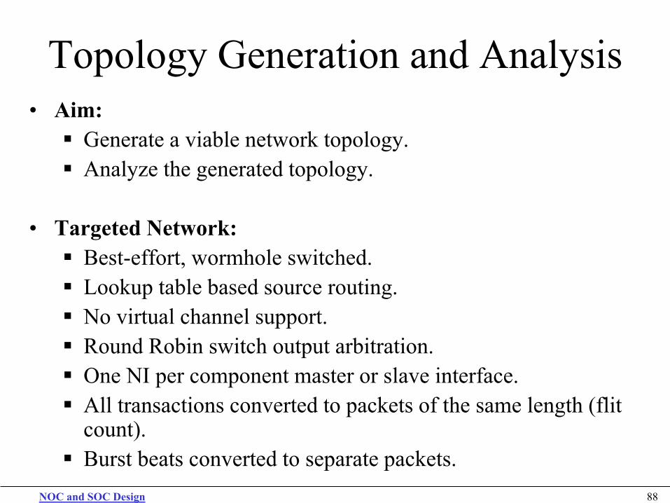
Topology Generation and Analysis • Aim: Generate a viable network topology. Analyze the generated topology.
• Targeted Network: Best-effort, wormhole switched. Lookup table based source routing. No virtual channel support. Round Robin switch output arbitration. One NI per component master or slave interface. All transactions converted to packets of the same length (flit
count). Burst beats converted to separate packets.
NOC and SOC Design 89
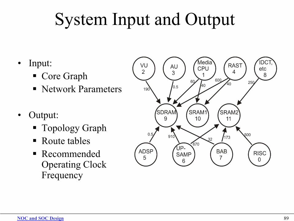
System Input and Output
• Input: Core Graph Network Parameters
• Output: Topology Graph Route tables Recommended
Operating Clock Frequency
NOC and SOC Design 90
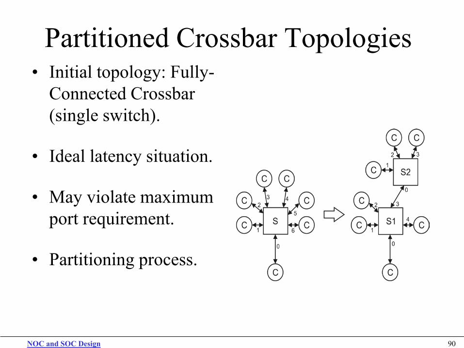
Partitioned Crossbar Topologies • Initial topology: Fully-
Connected Crossbar (single switch).
• Ideal latency situation.
• May violate maximum port requirement.
• Partitioning process.
NOC and SOC Design 91
Frequency Selection
• Cyclical relation between contention and frequency.
• Frequency is fixed before contention is analyzed. • To find minimum valid frequency: Interval halving process. Large number of frequency points.
NOC and SOC Design 92
Results
• Applications and generated topologies.
• Comparative results.
• Resource Usage.
• Accuracy tests.
NOC and SOC Design 93
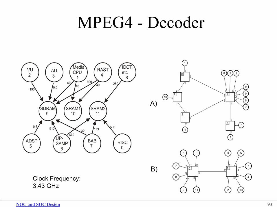
MPEG4 - Decoder
Clock Frequency: 3.43 GHz
A)
B)
NOC and SOC Design 94
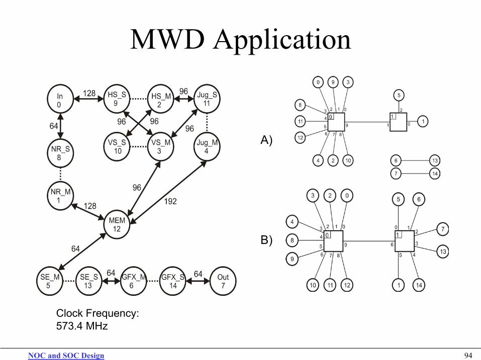
MWD Application
Clock Frequency: 573.4 MHz
A)
B)
NOC and SOC Design 95
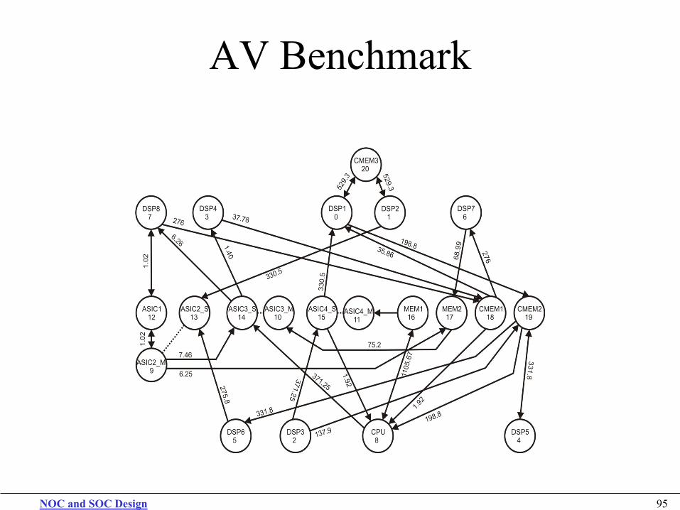
AV Benchmark
NOC and SOC Design 96
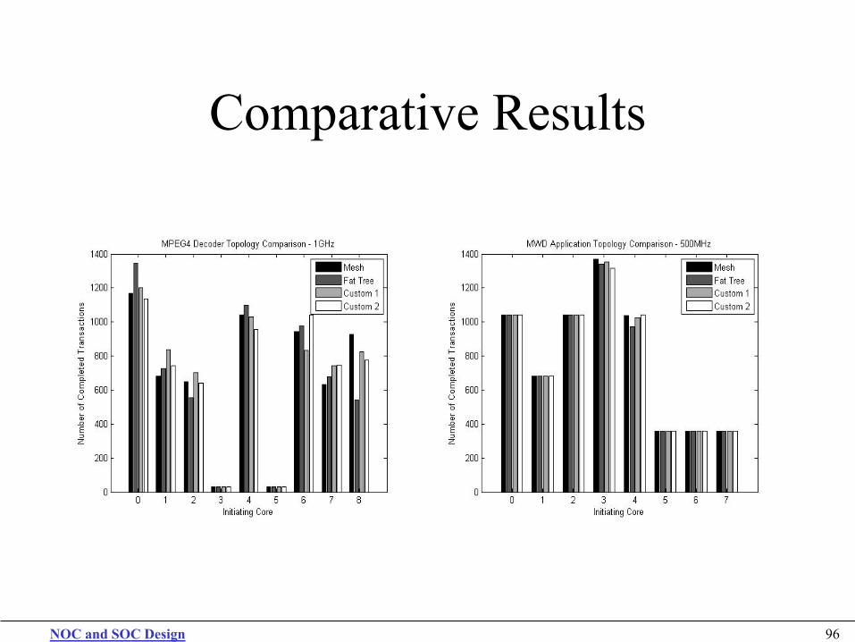
Comparative Results
NOC and SOC Design 97
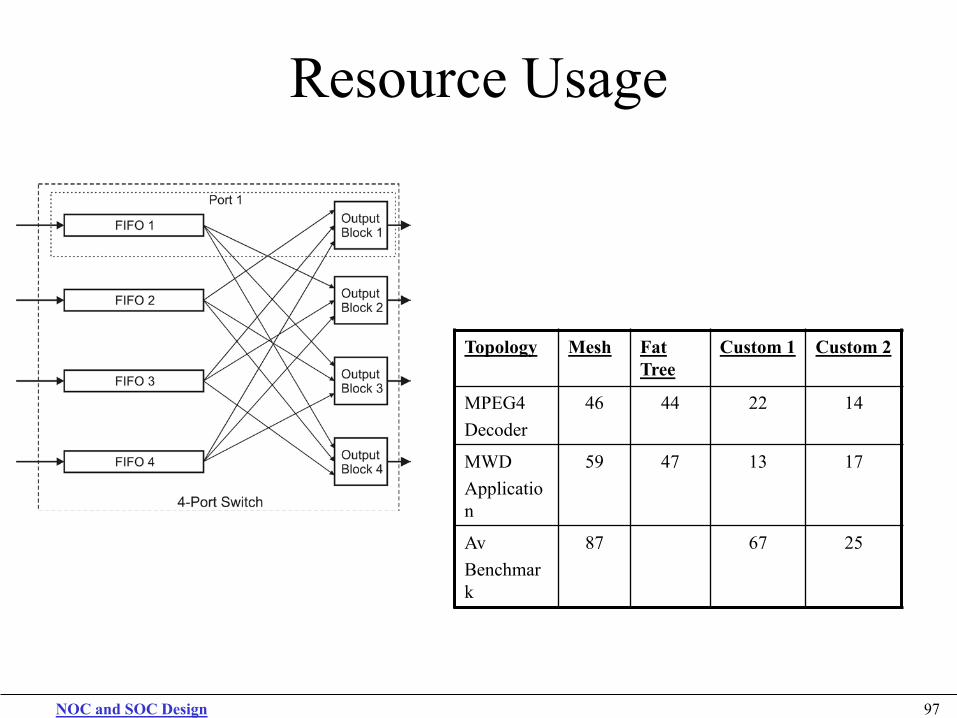
Resource Usage
Topology Mesh Fat Tree
Custom 1 Custom 2
MPEG4 Decoder
46 44 22 14
MWD Application
59 47 13 17
Av Benchmark
87 67 25
NOC and SOC Design 98
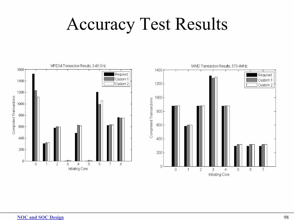
Accuracy Test Results


![COE838: System-on-Chip Designcourses/coe838/labs/HPS-FPGA...HPS/FPGA Interconnection COE838: System-on-Chip Design Lab 3 and 4, Project manual DE1-SoC Datasheets [online] Flynn and](https://img.pdfslide.us/doc/110x75/6098cc857676ac092725174a/coe838-system-on-chip-design-coursescoe838labshps-fpga-hpsfpga-interconnection.jpg)


![[Tutorial] NoC the Next Generation of Multi-Processor SoC](https://img.pdfslide.us/doc/110x75/55cf9bb1550346d033a70a13/tutorial-noc-the-next-generation-of-multi-processor-soc.jpg)