Embed Size (px)
Citation preview
Geophys. J. Int. (2011) 185, 1073–1089 doi: 10.1111/j.1365-246X.2011.04991.x
GJI
Geo
dyna
mic
san
dte
cton
ics
Geomechanical model of the Marmara Sea region—I. 3-Dcontemporary kinematics
Tobias Hergert,1,2,∗ Oliver Heidbach,3 Anne Becel2,4 and Mireille Laigle2
1Geophysical Institute, Karlsruhe Institute of Technology (KIT), Hertzstr. 16, 76187 Karlsruhe, Germany. E-mail: [email protected] of Seismology, UMR 7154, Institut de Physique du Globe de Paris, Case 89, Tour 24-14, 4eme etage, 4 Place Jussieu, 75252 Paris Cedex 05,France3GFZ German Research Centre for Geosciences, Section 2.6 Seismic Hazard and Stress Field, Telegrafenberg, 14773 Potsdam, Germany4CSIC-Instituto de Ciencias de la Tierra ‘Jaume Almera’, Dep. Estructura y Dinamica de la Tierra, Calle Lluis Sole i Sabaris, Barcelona, Spain
Accepted 2011 February 17. Received 2011 February 10; in original form 2010 February 12
S U M M A R YWe investigate by means of a 3-D geomechanical model the relationship between structuralelements and contemporary kinematics in the Marmara Sea region, northwest Turkey. Therecently imaged fault system beneath the Marmara Sea is incorporated into the model asfrictional surfaces with varying strike and dip. The Main Marmara Fault is implemented asthrough-going and is accompanied by mostly non-vertical second-order faults. Topography,basement-topography and the Moho become mechanically effective through changes in densityand elastic parameters across these horizons. The model is subjected to gravity and kinematicboundary conditions. The ultimate goal of this study is to set up a 3-D model that is con-sistent with both, kinematic observations and stress data. The stress results are presented ina complementary paper. In this paper we present the modelled long-term 3-D kinematics interms of fault slip rates, rotations, vertical motion and sense of fault slip. The model resultsagree with Global Positioning System velocities, geological fault slip rates, palaeomagneticmeasurements and with the observed pattern of subsidence and uplift. Furthermore, our tecton-ically driven vertical velocities can be linked to landscape and basin evolution and to featuresof sedimentation. Our results indicate that the Main Marmara Fault can be interpreted as athrough-going fault that slips almost purely in a strike-slip sense. Nevertheless, and not con-tradictory to the previous statement, there is significant dip-slip motion at some sections of theMain Marmara Fault. The agreement of the modelled 3-D kinematics with model-independentobservations supports that the main structural details of the fault system are accounted for.Sensitivity analysis of model parameters reveals that changes in rock properties and the initialstress state have minor influence on the 3-D kinematics. We conclude that the 3-D structureof the fault system is the key control of the kinematics. The slip rate of the Main MarmaraFault from our model is lower than previous estimates and shows high variability along strike(12.8–17.8 mm a–1). The latter indicates that stress accumulation is non-uniform along strike.
Key words: Numerical solutions; Plate motions; Geomechanics; Transform faults; Tectonicsand landscape evolution.
1 I N T RO D U C T I O N
With the 1999 Izmit earthquake a west-migrating sequence of strongearthquakes along the North Anatolian Fault (NAF) reached theeastern Marmara Sea region (Stein et al. 1997; Lorenzo-Martinet al. 2006). This event initiated numerous new research activitiesin the Marmara Sea to reveal the subsurface structure and kinematics
∗Now at: Landesforschungszentrum fur Geothermie, Institute for AppliedGeosciences, Karlsruhe Institute of Technology (KIT), Kaiserstrasse 12,76128 Karlsruhe, Germany.
with the broader goal to assess the seismic hazard of that region.Two results of these structural and kinematic investigations areof key importance. (1) The structure of the NAF in the MarmaraSea differs significantly from that further east where the NAF isprimarily a single vertical fault (Sengor et al. 2005). In the MarmaraSea region the NAF splits into three major branches and beneath theSea a complex fault system and deep basins with up to 6-km-thicksediment infill have been imaged (Le Pichon et al. 2001, 2003;Armijo et al. 2002; Parke et al. 2002; Carton et al. 2007; Laigleet al. 2008; Becel et al. 2009, 2010). (2) Fault slip rates derivedfrom geomechanical models that are constrained by interseismicGPS velocities are considerably higher than those derived from
C© 2011 The Authors 1073Geophysical Journal International C© 2011 RAS
Geophysical Journal International at Istanbul U
niversity on April 11, 2016
http://gji.oxfordjournals.org/D
ownloaded from
1074 T. Hergert et al.
geological and palaeoseismological investigations. The latter are inthe range of 14–19 mm a–1 (Armijo et al. 1999; Meghraoui et al.2004; Rockwell et al. 2006, 2009), whereas models that use GlobalPositioning System (GPS) data predict fault slip rates of 17–28mm a–1 on the northern branch of the NAF (Meade et al. 2002; LePichon et al. 2003; Flerit et al. 2004; Reilinger et al. 2006).
The state-of-the art knowledge of the subsurface structure belowthe Marmara Sea has been integrated into a geomechanical modelby Hergert & Heidbach (2010) to derive the long-term kinematics.This model quantifies the slip rate on the Main Marmara Fault(MMF) to between 12.8 and 17.8 mm a–1, which is markedly lowerthan previous estimates and similar to geological slip rates. Thelower slip rate can be referred to slip partitioning on second-orderfaults and to internal deformation in between the faults (Hergert &Heidbach 2010).
In this paper we present additional kinematic results of this modelsuch as rotation rates, dip slip rates and the sense of fault slip anddiscuss further comparison with other model-independent observa-tions. Furthermore, we investigate the sensitivity of the fault sliprates due to changes in fault friction and material properties andexplore the reliability of our slip rates with regard to boundaryconditions and possible post-seismic relaxation due to historicalearthquakes. We further discuss the implications of the results re-garding the interpretation of the fault system and seismic hazard.The overall goal of our study is to set up a model that fits consistentlythe 3-D kinematic and dynamic observations in the Marmara Searegion. In the complementary paper by Hergert & Heidbach (2011,herein referenced as Paper II) the dynamic results of this model arepresented.
2 G E O DY NA M I C A N D T E C T O N I CS E T T I N G
The NAF is a right-lateral strike-slip fault forming the boundarybetween the Anatolian Plate and the Eurasian Plate (Fig. 1a, Sengoret al. 2005). Along the NAF the Anatolian Plate escapes westwardsdue to the indentation of the Arabian Plate into Eurasia (McKenzie1972). This westward motion of Anatolia is permitted and facilitatedby the SSW-directed roll-back of the Hellenic subduction zone lead-ing to approximately NS-oriented backarc extension in the broaderAegean (Heidbach & Drewes 2003; Flerit et al. 2004). As a resultof this interaction of plates the Anatolian plate undergoes a counter-clockwise rotation (McClusky et al. 2000; Reilinger et al. 2006).The relative motion between the Anatolian Plate and the EurasianPlate along the NAF amounts to 24 ± 1 mm a–1 (McClusky et al.2000).
In NW Anatolia the NAF splays into three major branches(Armijo et al. 1999, 2002, Fig. 1b). The northern branch, termedMMF, enters the Marmara Sea at the Izmit Bay (Alpar & Yaltırak2002; Cormier et al. 2006) and passes through the Marmara Sea (LePichon et al. 2001, 2003). Further to the west it crosses the GeliboluPeninsula as the Ganos Fault and enters the Aegean at the Gulf ofSaros (Yaltırak & Alpar 2002a). The middle branch passes IznikLake, follows the southern shore of the Marmara Sea from GemlikBay to Kapıdag Peninsula where it turns to SW (Yaltırak & Alpar2002b; Kurtulus & Canbay 2007). The southern branch forms thesouthern rim of the Bursa Graben and enters the Aegean south ofBiga Peninsula.
Within the Marmara Sea the MMF exhibits three major bends(Fig. 1c): (1) the releasing bend at the western end of Izmit Bay(Tuzla Bend), (2) the bend SW of Istanbul (Istanbul Bend) and
(3) the restraining bend at the western Tekirdag Basin (GanosBend). The Prince’s Islands Segment between the Tuzla andIstanbul Bends steeply dips to SW and follows the base of a majorbathymetric scarp at the northern rim of the Cınarcık Basin (Cartonet al. 2007). The Central Segment between Istanbul Bend and theCentral Basin is rather straight and vertical. The Central Basin isbounded at its rims by secondary faults that dip towards the mainbranch (Laigle et al. 2008; Becel et al. 2010).
The MMF and associated secondary faults bound three majorbasins in the Marmara Sea that reach depths of over 1200 m bsl.(1) The Cınarcık Basin in the east, (2) the Central Basin in the mid-dle and (3) the Tekirdag Basin in the west. The basins are separatedby the Central High and the Western High, respectively. The ImralıBasin is associated with a north-dipping normal fault at its southernrim (Laigle et al. 2008). The basins are not only bathymetric de-pressions but are even more expressed in the basement topographysince the sediment thickness has now been imaged to exceed 6 kmin the Cınarcık and Central Basins (Carton et al. 2007; Laigle et al.2008).
Several tectonic models were proposed for the Marmara Sea.Based on the fault geometries it was interpreted as a system ofactive pull-apart basins (Armijo et al. 2002), or formerly activeones (Rangin et al. 2004). In another view the MMF is a sin-gle through-going pure strike-slip fault based on the observationthat focal mechanisms along the MMF show predominantly strike-slip faulting and that the fault trace comes close to a small circlearound the Euler pole of a Marmara block (Le Pichon et al. 2003).Interpretation of more recent seismic profiles suggests that thebasins are asymmetric half grabens (McHugh et al. 2006) and thattilting of huge basement blocks is involved (Laigle et al. 2008; Becelet al. 2009). Accordingly, the whole fault system would appear as alarge-scale negative flower structure (Aksu et al. 2000; Koral 2007;Laigle et al. 2008).
3 M O D E L C O N C E P T A N D I N P U T
The aim of this study is to quantify consistently the contemporary3-D kinematics and dynamics of the Marmara Sea region by meansof a 3-D geomechanical model. This involves the solution of thecomplete set of equations for the equilibrium of forces in threedimensions.
The workflow is divided into three major steps. (1) Model ge-ometry and rock properties: we implement the 3-D fault systemand integrate the major 3-D inhomogeneities of rock propertiesthat change across the basement-topography and the Moho. (2) Set-ting initial and boundary conditions, applying loads and numericalsolution: we define an initial stress state accounting for gravityand an appropriate ratio of horizontal to vertical stress. We applygravity and the load on the seafloor arising from the hydrostaticpressure exerted by the water column. We apply kinematic bound-ary conditions at the sides of the model, which we derive from aseparate model that fits the observed kinematics of NW Anatolia(so-called submodelling technique). Slip on frictional faults, de-formation and stress throughout the volume evolve in response tothe remotely acting forces associated with plate motion. The nu-merical solution is obtained by application of the finite-elementmethod. (3) Model results analysis: the model results are comparedwith model-independent observations. Sensitivity of the model re-sults due to model parameter uncertainties and assumptions isdiscussed.
C© 2011 The Authors, GJI, 185, 1073–1089
Geophysical Journal International C© 2011 RAS
at Istanbul University on A
pril 11, 2016http://gji.oxfordjournals.org/
Dow
nloaded from
Kinematics of the Marmara Sea region 1075
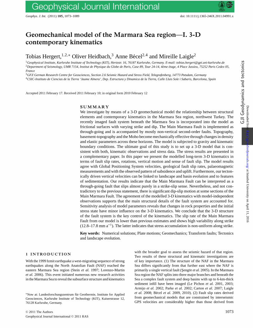
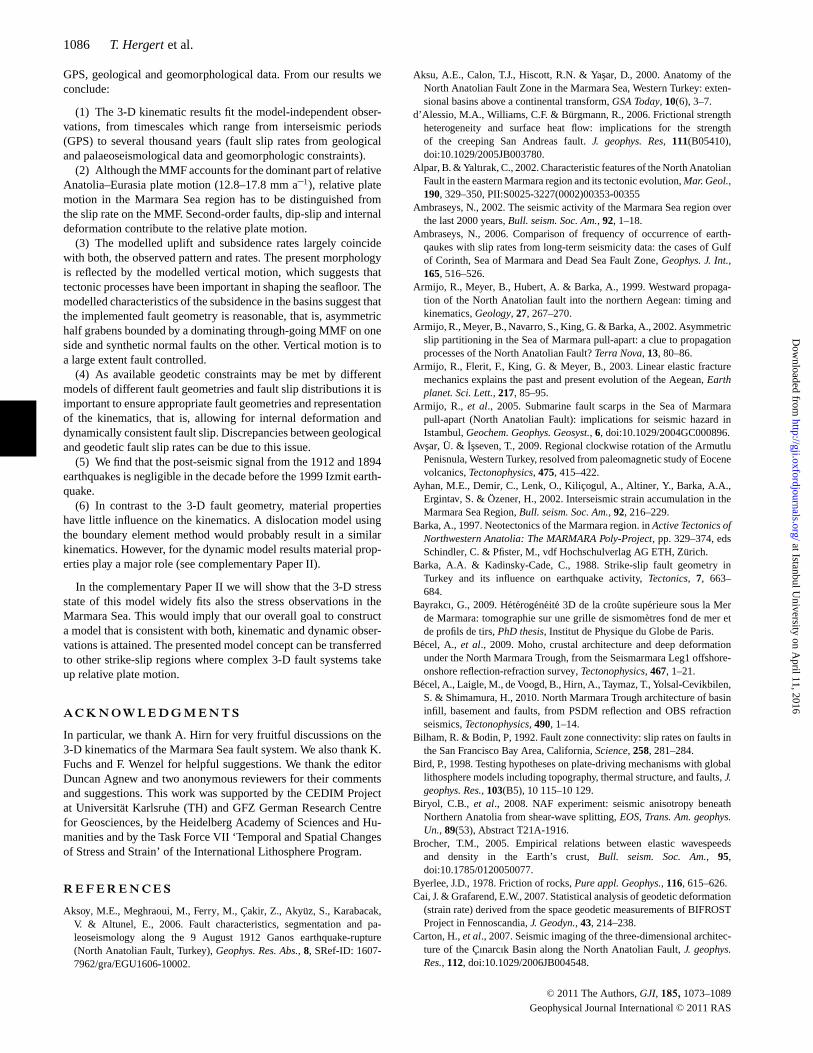
Figure 1. Geodynamic setting of the greater model area. (a) Tectonic map of the eastern Mediterranean. General plate motions (thick grey arrows) and GPSvelocities (Reilinger et al. 2006; thin white arrows) with respect to Eurasia. Black lines mark faults. (b) Northwest Anatolia (area of the regional model;supplementary fig. 2 in Hergert & Heidbach 2010). GPS velocities from Reilinger et al. (2006) (thin white arrows) (c) Marmara Sea region (area of theMarmara model). Bathymetry from Le Pichon et al. (2001) and faults from Armijo et al. (2002) and Carton et al. (2007).
C© 2011 The Authors, GJI, 185, 1073–1089
Geophysical Journal International C© 2011 RAS
at Istanbul University on A
pril 11, 2016http://gji.oxfordjournals.org/
Dow
nloaded from

1076 T. Hergert et al.
3.1 Model geometry and rock properties
The geometry of our 3-D geomechanical model has a rectangularshape (27.25–30.25◦E and 40.25–41.15◦N) with 250 km EW and100 km NS extent (Fig. 1c). The model is georeferenced in UTM(Universal Transverse Mercator) projection and its base is at 38 kmbsl., which is below the Moho. The geometry comprises horizonsthat represent the Moho, the basement-topography and the topogra-phy/bathymetry. These layers are transsected by faults.
3.1.1 Moho
The Moho beneath the Marmara Sea and its surroundings is char-acterized by significant undulations of ∼10 km and a regional min-imum depth right below the Sea. We generated a Moho map ofnorthwest Anatolia using Moho depth data from various seismicexperiments (Fig. S1, Supporting Information).
3.1.2 Topography, bathymetry and basement
Topography and bathymetry are incorporated into the modelusing the GTOPO30 digital elevation model (USGS) and thebathymetry of the North Marmara Trough (Le Pichon et al.2001). Constraints on the basement structure beneath the MarmaraSea predominantly come from the SEISMARMARA Leg 1 seis-mic reflection–refraction experiment (Carton et al. 2007; Laigleet al. 2008; Becel et al. 2009, 2010). A seismic velocity field wasobtained by a 3-D tomographic inversion of the first arrival times ofthe SEISMARMARA Leg 1 shots recorded by an ocean bottom seis-mometer array (Bayrakcı 2009). The basement-topography belowthe Marmara Sea was basically taken as the 4.5 km s–1 P-wave iso-velocity surface of a preliminary version of the 3-D velocity field.This velocity is typical for limestone that forms the pre-kinematicbasement beneath the Marmara Sea (Parke et al. 2002). The velocityiso-surface was locally modified to ensure that it coincides with thebasement-topography in depth-converted seismic sections and that itaccounts for the stratigraphic constraints from wells (Ergun & Ozel1995; Elmas 2003). Vertical offsets in the basement-topographywere established across those faults at which dip-slip is apparentin seismic profiles (Parke et al. 2002; Carton et al. 2007; Laigleet al. 2008). Outside the North Marmara Trough the basement-topography was constructed using the constraints from geologicalmaps (Elmas & Yigitbas 2001) and reasonable assumptions, suchas, that sediments are likely to be thick in topographic depressionsor near releasing fault bends since these are favoured places of sed-iment deposition. The incorporated basement-topography is shownin Fig. 2(b).
3.1.3 3-D fault system
We constructed the fault geometry based on mapped fault traces atthe seafloor, seismic sections and reasonable assumptions. We usedthe fault maps by Armijo et al. (2002), Cormier et al. (2006) andCarton et al. (2007) to constrain the upper termination of the faults.Information on the fault geometries in the subsurface comes fromseismic profiles (Parke et al. 2002; Carton et al. 2007; Laigle et al.2008; Becel et al. 2009). These allow at least relative estimates offault dips but absolute values of fault dips have also been suggested(Okay et al. 1999; Seeber et al. 2004; Kanbur et al. 2007; Becel et al.2010) or have been adopted to model the fault-related kinematics inthe Marmara Sea (Muller & Aydin 2005). Generally, faults beneath
the Marmara Sea dip rather steeply, also those, which are supposedto be normal faults.
In the case of uncertain fault geometry at depth we assumed thatthe fault trace at the surface is shifted to the west at depth due tothe west migration of the Anatolian block relative to Eurasia. Thus,a change in fault strike is accompanied by a non-vertical dip of thefault. Furthermore, from an energetic point of view it is favourablefor a fault to strike as straight as possible. Therefore, an apparentstep-over or a small fault bend at the seafloor must not necessarilyprolong at depth but likely adopts a more straight geometry. Atleast, this may be concluded from the rupture of the 1999 Izmitearthquake that revealed a straighter fault geometry in the IzmitBay than presumed before (Alpar & Yaltırak 2002; Cormier et al.2006). The dip direction of the implemented faults can be seen inFig. 2(a).
We assume the MMF to penetrate the model in its whole depth(38 km bsl.). This may be an appropriate assumption for a plateboundary fault and it was proposed by Aksu et al. (2000) thatthe MMF extends to depths greater than 30 km. We further assumethe MMF as being vertical below 15 km bsl. In the model the middlebranch of the NAF reaches down to 20 km bsl., the Cınarcık Fault,Imralı Fault and Tekirdag Fault to 15 km bsl., the Southern BorderFault to 10 km and the other faults to 7.5 km bsl.
In the Central Basin we assume the MMF as through-going, join-ing the southern inner rim of the basin in its uppermost part. Fig. 3shows the final set of faults that are implemented into the model.The faults change gradually in dip and strike and are represented inthe model by triangles whose size is ∼500 m. The changes in dipand strike are a key control for the kinematic and dynamic modelresults. The geometry of the model (3-D fault system, Moho andbasement-topography) is provided in the Supporting Information.
3.1.4 Coefficient of friction
We implement the faults as frictional surfaces. Relative motion onthese interfaces occurs when a critical shear stress is reached definedby the Mohr–Coulomb friction law.
τ = C0 + μ(σn − Pf ) = C0 + μ′σn. (1)
Here, τ is shear stress, C0 cohesion, μ the coefficient of friction,σ n normal stress and Pf pore fluid pressure. σ n is reduced by themagnitude of Pf , which facilitates fault slip. In the model an effec-tive coefficient of friction μ′ is assigned to the faults that implicitlyaccounts for Pf .
We assume C0 to be negligible (Jamison & Cook 1980). Althoughthe coefficient of friction μ of crustal rocks ranges between 0.6 and0.85 (Byerlee 1978), observations at large-offset plate boundaryfaults indicate that these faults are weak and have low (effective)friction coefficients (Zoback et al. 1987; Reasenberg & Simpson1992; Townend & Zoback 2004; d’Alessio et al. 2006), in agreementwith a number of numerical models (e.g. Bird 1998; Jimenez-Munt& Sabadini 2002; Provost et al. 2003; Vernant & Chery 2006). Wetest three different μ′ distributions: (1) uniform μ′ = 0.05 on allfaults, (2) μ′ = 0.03 on all faults and (3) μ′ = 0.05 on the MMFand μ′ = 0.6 on all other faults.
3.1.5 Rock properties
In this study, we apply linear elastic rheology. ‘Long-term’ elasticityexplains the effective elastic-brittle behaviour of continental crustalthough it is not elastic at all depths, and its capability to preserve
C© 2011 The Authors, GJI, 185, 1073–1089
Geophysical Journal International C© 2011 RAS
at Istanbul University on A
pril 11, 2016http://gji.oxfordjournals.org/
Dow
nloaded from
Kinematics of the Marmara Sea region 1077
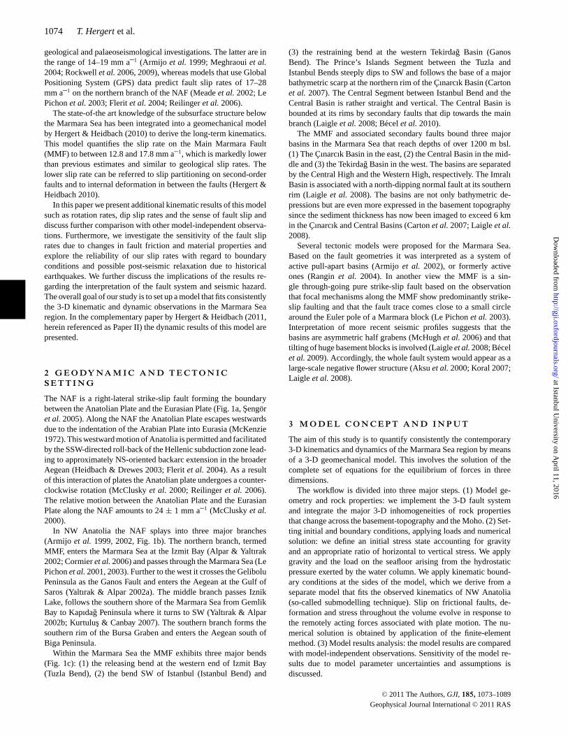
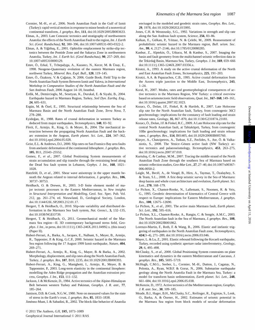
Figure 2. Fault system and basement-topography. (a) Topography and bathymetry. Fault traces at the surface (white lines) and at their lower ends (grey lines)indicate fault dips. (b) FE-mesh at the surface (grey), basement-topography where it is overlain by sediments (contours) and faults. Arrows show the viewdirection in Figs 3(c) and (d). (c) Cınarcık Basin. View from the northern shelf to ESE. Istanbul Bend (left), Izmit Bay (background, left), Central High(foreground, right), MMF (from background, left to foreground, right), inner (middle) and outer (right to background, left) Cınarcık Faults. White lines markfault traces at the sea bottom. Visible parts of the faults are within the sediments. Note the vertical step in basement-topography across the basin boundingfaults as revealed by Carton et al. (2007). (d) View from east to west. Central High (foreground), Central Basin (middle) and Tekirdag Basin (background).The MMF was assumed as a through-going fault joining the southern inner rim of the Central Basin.
C© 2011 The Authors, GJI, 185, 1073–1089
Geophysical Journal International C© 2011 RAS
at Istanbul University on A
pril 11, 2016http://gji.oxfordjournals.org/
Dow
nloaded from
1078 T. Hergert et al.
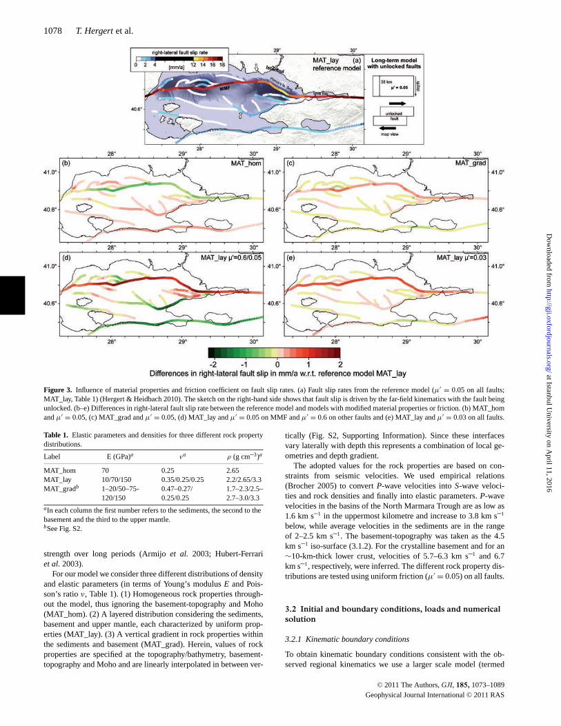
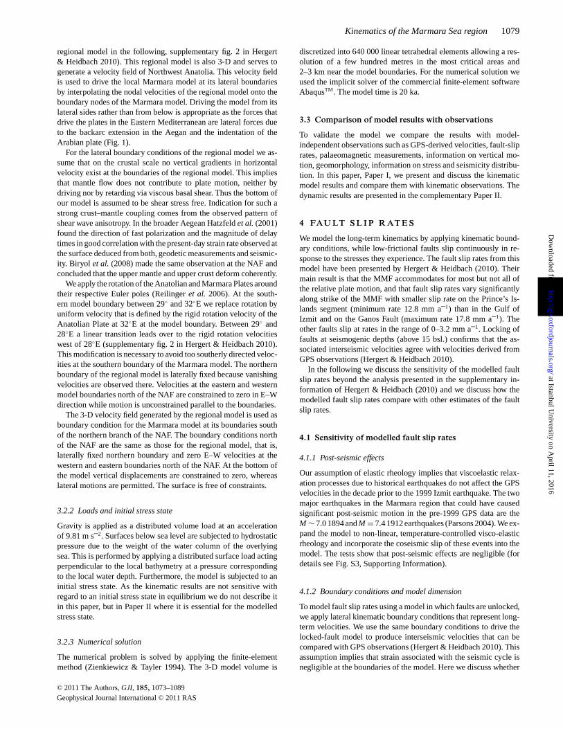
Figure 3. Influence of material properties and friction coefficient on fault slip rates. (a) Fault slip rates from the reference model (μ′ = 0.05 on all faults;MAT_lay, Table 1) (Hergert & Heidbach 2010). The sketch on the right-hand side shows that fault slip is driven by the far-field kinematics with the fault beingunlocked. (b–e) Differences in right-lateral fault slip rate between the reference model and models with modified material properties or friction. (b) MAT_homand μ′ = 0.05, (c) MAT_grad and μ′ = 0.05, (d) MAT_lay and μ′ = 0.05 on MMF and μ′ = 0.6 on other faults and (e) MAT_lay and μ′ = 0.03 on all faults.
Table 1. Elastic parameters and densities for three different rock propertydistributions.
Label E (GPa)a νa ρ (g cm–3)a
MAT_hom 70 0.25 2.65MAT_lay 10/70/150 0.35/0.25/0.25 2.2/2.65/3.3MAT_gradb 1–20/50–75- 0.47–0.27/ 1.7–2.3/2.5–
120/150 0.25/0.25 2.7–3.0/3.3aIn each column the first number refers to the sediments, the second to thebasement and the third to the upper mantle.bSee Fig. S2.
strength over long periods (Armijo et al. 2003; Hubert-Ferrariet al. 2003).
For our model we consider three different distributions of densityand elastic parameters (in terms of Young’s modulus E and Pois-son’s ratio ν, Table 1). (1) Homogeneous rock properties through-out the model, thus ignoring the basement-topography and Moho(MAT_hom). (2) A layered distribution considering the sediments,basement and upper mantle, each characterized by uniform prop-erties (MAT_lay). (3) A vertical gradient in rock properties withinthe sediments and basement (MAT_grad). Herein, values of rockproperties are specified at the topography/bathymetry, basement-topography and Moho and are linearly interpolated in between ver-
tically (Fig. S2, Supporting Information). Since these interfacesvary laterally with depth this represents a combination of local ge-ometries and depth gradient.
The adopted values for the rock properties are based on con-straints from seismic velocities. We used empirical relations(Brocher 2005) to convert P-wave velocities into S-wave veloci-ties and rock densities and finally into elastic parameters. P-wavevelocities in the basins of the North Marmara Trough are as low as1.6 km s–1 in the uppermost kilometre and increase to 3.8 km s–1
below, while average velocities in the sediments are in the rangeof 2–2.5 km s–1. The basement-topography was taken as the 4.5km s–1 iso-surface (3.1.2). For the crystalline basement and for an∼10-km-thick lower crust, velocities of 5.7–6.3 km s–1 and 6.7km s–1, respectively, were inferred. The different rock property dis-tributions are tested using uniform friction (μ′ = 0.05) on all faults.
3.2 Initial and boundary conditions, loads and numericalsolution
3.2.1 Kinematic boundary conditions
To obtain kinematic boundary conditions consistent with the ob-served regional kinematics we use a larger scale model (termed
C© 2011 The Authors, GJI, 185, 1073–1089
Geophysical Journal International C© 2011 RAS
at Istanbul University on A
pril 11, 2016http://gji.oxfordjournals.org/
Dow
nloaded from
Kinematics of the Marmara Sea region 1079
regional model in the following, supplementary fig. 2 in Hergert& Heidbach 2010). This regional model is also 3-D and serves togenerate a velocity field of Northwest Anatolia. This velocity fieldis used to drive the local Marmara model at its lateral boundariesby interpolating the nodal velocities of the regional model onto theboundary nodes of the Marmara model. Driving the model from itslateral sides rather than from below is appropriate as the forces thatdrive the plates in the Eastern Mediterranean are lateral forces dueto the backarc extension in the Aegan and the indentation of theArabian plate (Fig. 1).
For the lateral boundary conditions of the regional model we as-sume that on the crustal scale no vertical gradients in horizontalvelocity exist at the boundaries of the regional model. This impliesthat mantle flow does not contribute to plate motion, neither bydriving nor by retarding via viscous basal shear. Thus the bottom ofour model is assumed to be shear stress free. Indication for such astrong crust–mantle coupling comes from the observed pattern ofshear wave anisotropy. In the broader Aegean Hatzfeld et al. (2001)found the direction of fast polarization and the magnitude of delaytimes in good correlation with the present-day strain rate observed atthe surface deduced from both, geodetic measurements and seismic-ity. Biryol et al. (2008) made the same observation at the NAF andconcluded that the upper mantle and upper crust deform coherently.
We apply the rotation of the Anatolian and Marmara Plates aroundtheir respective Euler poles (Reilinger et al. 2006). At the south-ern model boundary between 29◦ and 32◦E we replace rotation byuniform velocity that is defined by the rigid rotation velocity of theAnatolian Plate at 32◦E at the model boundary. Between 29◦ and28◦E a linear transition leads over to the rigid rotation velocitieswest of 28◦E (supplementary fig. 2 in Hergert & Heidbach 2010).This modification is necessary to avoid too southerly directed veloc-ities at the southern boundary of the Marmara model. The northernboundary of the regional model is laterally fixed because vanishingvelocities are observed there. Velocities at the eastern and westernmodel boundaries north of the NAF are constrained to zero in E–Wdirection while motion is unconstrained parallel to the boundaries.
The 3-D velocity field generated by the regional model is used asboundary condition for the Marmara model at its boundaries southof the northern branch of the NAF. The boundary conditions northof the NAF are the same as those for the regional model, that is,laterally fixed northern boundary and zero E–W velocities at thewestern and eastern boundaries north of the NAF. At the bottom ofthe model vertical displacements are constrained to zero, whereaslateral motions are permitted. The surface is free of constraints.
3.2.2 Loads and initial stress state
Gravity is applied as a distributed volume load at an accelerationof 9.81 m s–2. Surfaces below sea level are subjected to hydrostaticpressure due to the weight of the water column of the overlyingsea. This is performed by applying a distributed surface load actingperpendicular to the local bathymetry at a pressure correspondingto the local water depth. Furthermore, the model is subjected to aninitial stress state. As the kinematic results are not sensitive withregard to an initial stress state in equilibrium we do not describe itin this paper, but in Paper II where it is essential for the modelledstress state.
3.2.3 Numerical solution
The numerical problem is solved by applying the finite-elementmethod (Zienkiewicz & Tayler 1994). The 3-D model volume is
discretized into 640 000 linear tetrahedral elements allowing a res-olution of a few hundred metres in the most critical areas and2–3 km near the model boundaries. For the numerical solution weused the implicit solver of the commercial finite-element softwareAbaqusTM. The model time is 20 ka.
3.3 Comparison of model results with observations
To validate the model we compare the results with model-independent observations such as GPS-derived velocities, fault-sliprates, palaeomagnetic measurements, information on vertical mo-tion, geomorphology, information on stress and seismicity distribu-tion. In this paper, Paper I, we present and discuss the kinematicmodel results and compare them with kinematic observations. Thedynamic results are presented in the complementary Paper II.
4 FAU LT S L I P R AT E S
We model the long-term kinematics by applying kinematic bound-ary conditions, while low-frictional faults slip continuously in re-sponse to the stresses they experience. The fault slip rates from thismodel have been presented by Hergert & Heidbach (2010). Theirmain result is that the MMF accommodates for most but not all ofthe relative plate motion, and that fault slip rates vary significantlyalong strike of the MMF with smaller slip rate on the Prince’s Is-lands segment (minimum rate 12.8 mm a–1) than in the Gulf ofIzmit and on the Ganos Fault (maximum rate 17.8 mm a–1). Theother faults slip at rates in the range of 0–3.2 mm a–1. Locking offaults at seismogenic depths (above 15 bsl.) confirms that the as-sociated interseismic velocities agree with velocities derived fromGPS observations (Hergert & Heidbach 2010).
In the following we discuss the sensitivity of the modelled faultslip rates beyond the analysis presented in the supplementary in-formation of Hergert & Heidbach (2010) and we discuss how themodelled fault slip rates compare with other estimates of the faultslip rates.
4.1 Sensitivity of modelled fault slip rates
4.1.1 Post-seismic effects
Our assumption of elastic rheology implies that viscoelastic relax-ation processes due to historical earthquakes do not affect the GPSvelocities in the decade prior to the 1999 Izmit earthquake. The twomajor earthquakes in the Marmara region that could have causedsignificant post-seismic motion in the pre-1999 GPS data are theM ∼ 7.0 1894 and M = 7.4 1912 earthquakes (Parsons 2004). We ex-pand the model to non-linear, temperature-controlled visco-elasticrheology and incorporate the coseismic slip of these events into themodel. The tests show that post-seismic effects are negligible (fordetails see Fig. S3, Supporting Information).
4.1.2 Boundary conditions and model dimension
To model fault slip rates using a model in which faults are unlocked,we apply lateral kinematic boundary conditions that represent long-term velocities. We use the same boundary conditions to drive thelocked-fault model to produce interseismic velocities that can becompared with GPS observations (Hergert & Heidbach 2010). Thisassumption implies that strain associated with the seismic cycle isnegligible at the boundaries of the model. Here we discuss whether
C© 2011 The Authors, GJI, 185, 1073–1089
Geophysical Journal International C© 2011 RAS
at Istanbul University on A
pril 11, 2016http://gji.oxfordjournals.org/
Dow
nloaded from
1080 T. Hergert et al.
actually interseismic velocities correspond to long-term velocitiesat the boundaries of the model and whether the applied boundaryconditions are appropriate to derive fault slip rates.
Mayer & Lu (2001) inferred the pre-1999 strain profile acrossthe NAF from InSAR observations of this earthquake. They foundthat the area affected by coseismic surface displacement was ∼55km on either side of the fault and they estimated that 50 per centof strain was stored within a distance of 10 km of the fault becauseof the rapid decay of strain with distance from the fault. Our modelhas a north–south width of 100 km with the main branch right inthe middle so that the dimensions of the model are such that theinterseismic strain essentially vanishes at the boundaries.
To check this in more detail we estimate the long-term velocityat GPS site SILE (Reilinger et al. 2006), which is located closeto the northern boundary of the Marmara model. At this site thehorizontal velocity during the decade prior to the 1999 Izmit earth-quake was 0.85 ± 1.25 mm a–1 to the west (Reilinger et al. 2006).The coseismic displacement during the Izmit earthquake was 11.91cm to the east (Reilinger et al. 2000). If we assume that the SILEsite moves at the pre-Izmit velocity during the whole interseismicperiod of ∼280 yr (1719–1999), then we obtain a long-term veloc-ity of 0.42 mm a–1 to the west. However, this is an upper boundfor the long-term west velocity because post-seismic processes addan east-directed component. So our fixed northern model boundaryover the long term is a fair assumption for our estimation of thefault slip rate.
At the southern model boundary interseismic deformation arisingfrom the locked middle and southern branches of the NAF maybe relevant so that long-term velocities near the southern modelboundary may be little greater than those observed and applied.However, the slip rate on these faults is rather small. Hergert &Heidbach (2010) showed that a 10 per cent increase in velocitiesat the southern boundary of the regional model would increaseresulting slip rates by 2 mm a–1.
4.1.3 Material parameters and coefficient of friction
We also investigate the influence of the material properties and thecoefficient of friction on the modelled slip rates beyond the testspresented in the supplementary information of Hergert & Heid-bach (2010). At first we keep friction constant (μ′ = 0.05 on allfaults) and vary density and elastic parameters. Fault slip rates onthe MMF from the homogeneous model (MAT_hom, Table 1) arelower by maximum 1.0 mm a–1 compared to the rates from themodel with layered rock properties (MAT_lay, Table 1), whereasslip rates on the other faults are slightly greater by <0.5 mm a–1
(Fig. 3b). The model with vertical gradients in rock properties(MAT_grad, Table 1) yields greater (<0.7 mm a–1) slip rates onthe MMF than the MAT_lay model (Fig. 3c). The greater MMFslip rates resulting from the inhomogeneous models compared tothe homogeneous model can be referred to their greater Young’smodulus in the lower crust and to their lower density of the sedi-ments (Table 1, Fig. S2). The effect of greater Young’s modulus,hence stiffer material, is that deformation becomes more localizedat faults and that internal deformation is hampered. Besides, veloc-ities at the model boundary are transmitted more effectively intothe interior of the model volume. The effect of lower densitiesis reduced lithostatic stress at depth and hence lower fault normalstress, which at the same coefficient of friction results in greater sliprates. To summarize, the influence of changes in rock properties onfault slip rates is for the investigated cases at most 1.2 mm a–1
(Figs 3b and c).
In the following tests we keep the MAT_lay rock properties andvary fault friction. Assigning μ′ = 0.6 to all faults except theMMF (μ′ = 0.05) reduces slip rates on the smaller faults by up to1.8 mm a–1, whereas the slip rate on the MMF increases by thesame amount (Fig. 3d). For μ′ = 0.03 on all faults the slip rate onthe MMF increases by <1.0 mm a–1, but slip rates on the otherfaults show only minor changes (Fig. 3e).
The coefficient of friction apparently rules the relative impor-tance of localized fault slip and distributed deformation. In case ofdecoupled blocks at low μ′ deformation is localized at faults. Dis-tributed deformation in the volume gains importance as the degreeof coupling increases with higher fault friction. In the model thisrelationship between off-fault deformation and fault slip is estab-lished as being dynamically consistent. The two alternative frictiondistributions in favour of increased slip rates on the MMF due toreduced slip partitioning (Fig. 3d) and reduced internal deformation(Fig. 3e) yield at most a 1.8 mm a–1 greater MMF slip rate.
The interseismic velocities from a model with altered elasticparameters fit the GPS observations similarly well (Hergert &Heidbach 2010). Also different friction coefficients on the sec-ondary faults do not affect interseismic velocities because thesefaults terminate above the assumed locking depth of 15 km (Sec-tion 3.1.3).
4.2 Comparison with reported fault slip rates
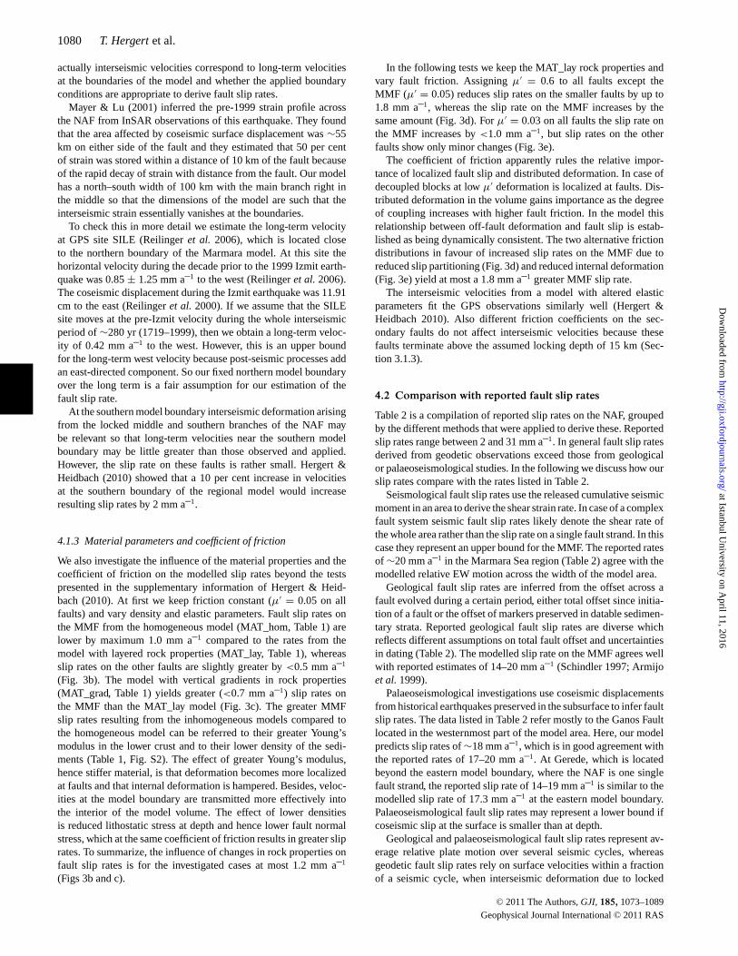
Table 2 is a compilation of reported slip rates on the NAF, groupedby the different methods that were applied to derive these. Reportedslip rates range between 2 and 31 mm a–1. In general fault slip ratesderived from geodetic observations exceed those from geologicalor palaeoseismological studies. In the following we discuss how ourslip rates compare with the rates listed in Table 2.
Seismological fault slip rates use the released cumulative seismicmoment in an area to derive the shear strain rate. In case of a complexfault system seismic fault slip rates likely denote the shear rate ofthe whole area rather than the slip rate on a single fault strand. In thiscase they represent an upper bound for the MMF. The reported ratesof ∼20 mm a–1 in the Marmara Sea region (Table 2) agree with themodelled relative EW motion across the width of the model area.
Geological fault slip rates are inferred from the offset across afault evolved during a certain period, either total offset since initia-tion of a fault or the offset of markers preserved in datable sedimen-tary strata. Reported geological fault slip rates are diverse whichreflects different assumptions on total fault offset and uncertaintiesin dating (Table 2). The modelled slip rate on the MMF agrees wellwith reported estimates of 14–20 mm a–1 (Schindler 1997; Armijoet al. 1999).
Palaeoseismological investigations use coseismic displacementsfrom historical earthquakes preserved in the subsurface to infer faultslip rates. The data listed in Table 2 refer mostly to the Ganos Faultlocated in the westernmost part of the model area. Here, our modelpredicts slip rates of ∼18 mm a–1, which is in good agreement withthe reported rates of 17–20 mm a–1. At Gerede, which is locatedbeyond the eastern model boundary, where the NAF is one singlefault strand, the reported slip rate of 14–19 mm a–1 is similar to themodelled slip rate of 17.3 mm a–1 at the eastern model boundary.Palaeoseismological fault slip rates may represent a lower bound ifcoseismic slip at the surface is smaller than at depth.
Geological and palaeoseismological fault slip rates represent av-erage relative plate motion over several seismic cycles, whereasgeodetic fault slip rates rely on surface velocities within a fractionof a seismic cycle, when interseismic deformation due to locked
C© 2011 The Authors, GJI, 185, 1073–1089
Geophysical Journal International C© 2011 RAS
at Istanbul University on A
pril 11, 2016http://gji.oxfordjournals.org/
Dow
nloaded from
Kinematics of the Marmara Sea region 1081
Table 2. Compilation of right-lateral fault slip rates.
Slip rate(mm a–1) Fault/Location Reference
Seismological data31 NAF Jackson & McKenzie (1984)24 Marmara region Eyidogan (1988)16 NAF western part Kiratzi (1993)16/12.1 Western NAF/Marmara Sea Kiratzi & Papazachos (1995)∼ 20 Marmara region Papazachos & Kiratzi (1996)5.6 Marmara region @ 31◦E Pınar et al. (1996)16–24/3 Marmara region/southern
branchAmbraseys (2002)
20 ± 4 Marmara region Ambraseys (2006)
Geological data5–8 NAF Barka & Kadinsky-Cade
(1988)2–4 Northern branch Barka (1997)14–20 Northern branch Schindler (1997)17 Marmara region Armijo et al. (1999)14 Northern branch Armijo et al. (1999)18 ± 3.5 Central NAF Hubert-Ferrari et al. (2002)10.5 ±1.5
NAF in western Izmit Bay Polonia et al. (2004)
20.5 ±5.5
Central NAF (Eksik) Kozacı et al. (2007)
18.6 ±3.5
Central NAF (Tahtakopru) Kozacı et al. (2009)
Palaeoseismological data18 Ganos Fault (Saros Bay) Rockwell et al. (2001)≥ 17 Ganos Fault Meghraoui et al. (2004)18 Ganos Fault Rockwell et al. (2006)14–18/19 NAF (Gerede/1944 eq.) Rockwell et al. (2006)17.5–20 Ganos Fault Aksoy et al. (2006)6.3 Yenice-Gonen Fault Kurcer et al. (2008)
GPS data directly25 NAF Oral et al. (1995)22.9 NAF Noomen et al. (1996)22 ± 3 Marmara region Straub et al. (1997)≤ 24 ± 1 NAF McClusky et al. (2000)11/13/26 Izmit/Izmit Bay/Marmara Sea Ayhan et al. (2002)24–25 NAF Reilinger et al. (2006)
GPS data in combination with rotation around a pole16/19 NAF @ 30◦E / Marmara Westaway (1994)28 NAF Le Pichon et al. (1995)23 MMF, including Prince’s
Islands SegmentLe Pichon et al. (2003)
GPS data in combination with geomechanical modelling24/6 Northern/southern branch Meade et al. (2002)17 NAF Provost et al. (2003)17–20 Northern branch Flerit et al. (2004)18–24 Ganos Fault Motagh et al. (2007)
3-D geomechanical model of this study12.8 Prince’s Islands segment Fig. 3(a)15.8 Northern branch @ 29.5◦E Fig. 3(a)17.8 Ganos Fault Fig. 3(a)3.2 Middle branch @ 29.5◦E Fig. 3(a)
faults is effective. A first-order approach to derive fault slip ratesfrom geodetic observations is to use the difference in fault-parallelinterseismic GPS velocities observed at either side of the fault andat some distance to the fault where the interseismic effect is small.This implies rigid-block rheology (which makes it a lower-bound es-timate because interseismic deformation pretends a smaller relativemotion) and refers the difference in velocity between the GPS sites
exclusively to slip on the considered fault in between (which makesit an upper-bound estimate). In a similar way, rigid blocks have beendefined that rotate at a rate and around a pole such that interseis-mic GPS velocities distributed over a larger area are optimally fitted(Le Pichon et al. 2003; Westaway 1994). Another approach to derivefault slip rates from interseismic GPS data is to use geomechanicalmodels in which faults are embedded in deformable half-space andwhich relate the fault slip below a given locking depth to the surfacevelocities that fit the interseismic GPS data best. The derived faultslip rates depend in particular on the details of the fault geometries.
There are three studies providing slip rates for particular faultsegments in the Marmara Sea region from GPS-constrained geome-chanical models (Meade et al. 2002; Flerit et al. 2004; Reilingeret al. 2006). Fig. S4 (Supporting Information) shows the adoptedfault geometries and the pertaining slip rates, which are 24.4–24.8mm a–1 (Meade et al. 2002), 24.6–27.9 mm a–1 (Reilinger et al.2006) and 17–20 mm a–1 (Flerit et al. 2004) on the MMF. Our sliprates (Fig. 3a) are significantly smaller and show high variabilityalong fault strike. The slip rate on the MMF has been regarded asbeing uniform on its whole length, including the northern Cınarcıkmargin (Le Pichon et al. 2003), whereas our results show 5 mm a–1
variability of slip rate along the MMF (Fig. 3a).The apparent conflict between geodetical and geologi-
cal/palaeoseismological fault slip rates is commonly explainedby evoking temporal changes in fault slip rates as the differentmethods capture time periods of different length (100–101a versus102–106a). However, our results show that geodetic and geologi-cal/palaeoseismological fault slip rates can well be reconciled inthe Marmara region because our fault slip rates agree with geo-logical/palaeoseismological slip rates (Table 2) and fit the geodeticobservations (Hergert & Heidbach 2010).
4.3 Origin of deviations in right-lateral fault slip rates
Even though the previous models and ours are constrained by es-sentially the same GPS observations and though all models fit theobservations equally well, the resulting fault slip rates differ con-siderably from each other. This shows that fitting interseismic GPSvelocities depends much on the adopted fault geometries and onwhether internal deformation and a dynamically consistent evolu-tion of fault slip is permitted. Hergert & Heidbach (2010) showedthat the smaller fault slip rates predicted by this model can beattributed to (1) slip partitioning, that is, second-order faults con-tribute to relative plate motion thereby lowering the slip rate on theMMF (2) internal deformation, that is, deformation in the volumebetween faults, which may be comprised of rotations, permanentstrain and slip on smaller faults not considered in the model and(3) dip-slip on non-vertical faults that strike oblique to the overallE–W direction of plate motion in the Marmara Sea region. Note,that part of relative plate motion is accommodated also beyond thesouthern boundary of the model, probably most of it on the southernbranch of the NAF.
Slip partitioning has also been observed in other strike-slip faultsystems such as the San Andreas Fault in California where it isparalleled by the Hayward, Calaveras, San Jacinto and other faults(Bilham & Bodin 1992; Geist & Andrews 2000), the Alpine Faultin New Zealand where it splits into the Marlborough Fault system(Norris & Cooper 2000) and the Dead Sea Fault that splits intothe Yammouneh and Serghaya Faults (Gomez et al. 2007). Themechanism of slip partitioning is also effective through oblique anddip-slip motion on non-vertical faults. As a consequence of slip
C© 2011 The Authors, GJI, 185, 1073–1089
Geophysical Journal International C© 2011 RAS
at Istanbul University on A
pril 11, 2016http://gji.oxfordjournals.org/
Dow
nloaded from
1082 T. Hergert et al.
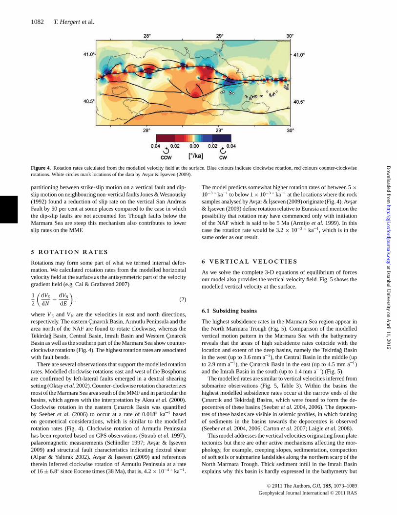
Figure 4. Rotation rates calculated from the modelled velocity field at the surface. Blue colours indicate clockwise rotation, red colours counter-clockwiserotations. White circles mark locations of the data by Avsar & Isseven (2009).
partitioning between strike-slip motion on a vertical fault and dip-slip motion on neighbouring non-vertical faults Jones & Wesnousky(1992) found a reduction of slip rate on the vertical San AndreasFault by 50 per cent at some places compared to the case in whichthe dip-slip faults are not accounted for. Though faults below theMarmara Sea are steep this mechanism also contributes to lowerslip rates on the MMF.
5 RO TAT I O N R AT E S
Rotations may form some part of what we termed internal defor-mation. We calculated rotation rates from the modelled horizontalvelocity field at the surface as the antisymmetric part of the velocitygradient field (e.g. Cai & Grafarend 2007)
1
2
(dVE
dN− dVN
dE
), (2)
where VE and VN are the velocities in east and north directions,respectively. The eastern Cınarcık Basin, Armutlu Peninsula and thearea north of the NAF are found to rotate clockwise, whereas theTekirdag Basin, Central Basin, Imralı Basin and Western CınarcıkBasin as well as the southern part of the Marmara Sea show counter-clockwise rotations (Fig. 4). The highest rotation rates are associatedwith fault bends.
There are several observations that support the modelled rotationrates. Modelled clockwise rotations east and west of the Bosphorusare confirmed by left-lateral faults emerged in a dextral shearingsetting (Oktay et al. 2002). Counter-clockwise rotation characterizesmost of the Marmara Sea area south of the MMF and in particular thebasins, which agrees with the interpretation by Aksu et al. (2000).Clockwise rotation in the eastern Cınarcık Basin was quantifiedby Seeber et al. (2006) to occur at a rate of 0.018◦ ka–1 basedon geometrical considerations, which is similar to the modelledrotation rates (Fig. 4). Clockwise rotation of Armutlu Peninsulahas been reported based on GPS observations (Straub et al. 1997),palaeomagnetic measurements (Schindler 1997; Avsar & Isseven2009) and structural fault characteristics indicating dextral shear(Alpar & Yaltırak 2002). Avsar & Isseven (2009) and referencestherein inferred clockwise rotation of Armutlu Peninsula at a rateof 16 ± 6.8◦ since Eocene times (38 Ma), that is, 4.2 × 10⁻⁴ ◦ ka–1.
The model predicts somewhat higher rotation rates of between 5 ×10⁻³ ◦ ka–1 to below 1 × 10⁻³ ◦ ka–1 at the locations where the rocksamples analysed by Avsar & Isseven (2009) originate (Fig. 4). Avsar& Isseven (2009) define rotation relative to Eurasia and mention thepossibility that rotation may have commenced only with initiationof the NAF which is said to be 5 Ma (Armijo et al. 1999). In thiscase the rotation rate would be 3.2 × 10⁻³ ◦ ka–1, which is in thesame order as our result.
6 V E RT I C A L V E L O C T I E S
As we solve the complete 3-D equations of equilibrium of forcesour model also provides the vertical velocity field. Fig. 5 shows themodelled vertical velocity at the surface.
6.1 Subsiding basins
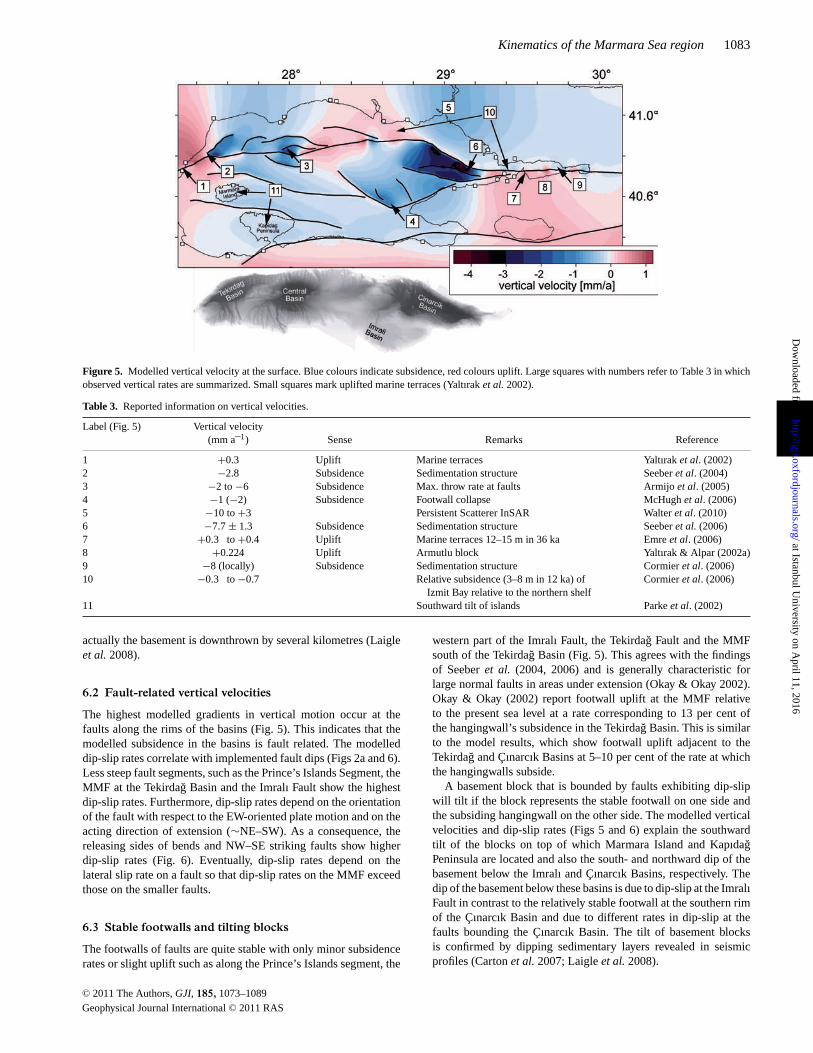
The highest subsidence rates in the Marmara Sea region appear inthe North Marmara Trough (Fig. 5). Comparison of the modelledvertical motion pattern in the Marmara Sea with the bathymetryreveals that the areas of high subsidence rates coincide with thelocation and extent of the deep basins, namely the Tekirdag Basinin the west (up to 3.6 mm a–1), the Central Basin in the middle (upto 2.9 mm a–1), the Cınarcık Basin in the east (up to 4.5 mm a–1)and the Imralı Basin in the south (up to 1.4 mm a–1) (Fig. 5).
The modelled rates are similar to vertical velocities inferred fromsubmarine observations (Fig. 5, Table 3). Within the basins thehighest modelled subsidence rates occur at the narrow ends of theCınarcık and Tekirdag Basins, which were found to form the de-pocentres of these basins (Seeber et al. 2004, 2006). The depocen-tres of these basins are visible in seismic profiles, in which fanningof sediments in the basins towards the depocentres is observed(Seeber et al. 2004, 2006; Carton et al. 2007; Laigle et al. 2008).
This model addresses the vertical velocities originating from platetectonics but there are other active mechanisms affecting the mor-phology, for example, creeping slopes, sedimentation, compactionof soft soils or submarine landslides along the northern scarp of theNorth Marmara Trough. Thick sediment infill in the Imralı Basinexplains why this basin is hardly expressed in the bathymetry but
C© 2011 The Authors, GJI, 185, 1073–1089
Geophysical Journal International C© 2011 RAS
at Istanbul University on A
pril 11, 2016http://gji.oxfordjournals.org/
Dow
nloaded from
Kinematics of the Marmara Sea region 1083
Figure 5. Modelled vertical velocity at the surface. Blue colours indicate subsidence, red colours uplift. Large squares with numbers refer to Table 3 in whichobserved vertical rates are summarized. Small squares mark uplifted marine terraces (Yaltırak et al. 2002).
Table 3. Reported information on vertical velocities.
Label (Fig. 5) Vertical velocity(mm a–1) Sense Remarks Reference
1 +0.3 Uplift Marine terraces Yaltırak et al. (2002)2 −2.8 Subsidence Sedimentation structure Seeber et al. (2004)3 −2 to −6 Subsidence Max. throw rate at faults Armijo et al. (2005)4 −1 (−2) Subsidence Footwall collapse McHugh et al. (2006)5 −10 to +3 Persistent Scatterer InSAR Walter et al. (2010)6 −7.7 ± 1.3 Subsidence Sedimentation structure Seeber et al. (2006)7 +0.3 to +0.4 Uplift Marine terraces 12–15 m in 36 ka Emre et al. (2006)8 +0.224 Uplift Armutlu block Yaltırak & Alpar (2002a)9 −8 (locally) Subsidence Sedimentation structure Cormier et al. (2006)10 −0.3 to −0.7 Relative subsidence (3–8 m in 12 ka) of
Izmit Bay relative to the northern shelfCormier et al. (2006)
11 Southward tilt of islands Parke et al. (2002)
actually the basement is downthrown by several kilometres (Laigleet al. 2008).
6.2 Fault-related vertical velocities
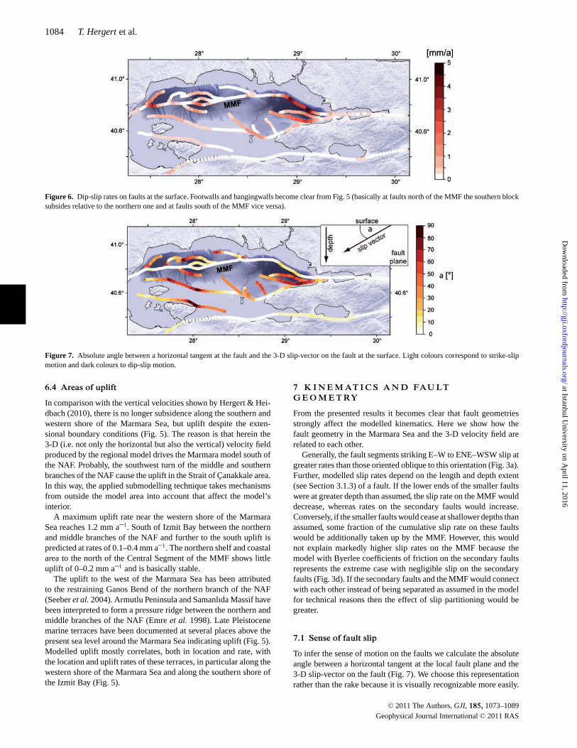
The highest modelled gradients in vertical motion occur at thefaults along the rims of the basins (Fig. 5). This indicates that themodelled subsidence in the basins is fault related. The modelleddip-slip rates correlate with implemented fault dips (Figs 2a and 6).Less steep fault segments, such as the Prince’s Islands Segment, theMMF at the Tekirdag Basin and the Imralı Fault show the highestdip-slip rates. Furthermore, dip-slip rates depend on the orientationof the fault with respect to the EW-oriented plate motion and on theacting direction of extension (∼NE–SW). As a consequence, thereleasing sides of bends and NW–SE striking faults show higherdip-slip rates (Fig. 6). Eventually, dip-slip rates depend on thelateral slip rate on a fault so that dip-slip rates on the MMF exceedthose on the smaller faults.
6.3 Stable footwalls and tilting blocks
The footwalls of faults are quite stable with only minor subsidencerates or slight uplift such as along the Prince’s Islands segment, the
western part of the Imralı Fault, the Tekirdag Fault and the MMFsouth of the Tekirdag Basin (Fig. 5). This agrees with the findingsof Seeber et al. (2004, 2006) and is generally characteristic forlarge normal faults in areas under extension (Okay & Okay 2002).Okay & Okay (2002) report footwall uplift at the MMF relativeto the present sea level at a rate corresponding to 13 per cent ofthe hangingwall’s subsidence in the Tekirdag Basin. This is similarto the model results, which show footwall uplift adjacent to theTekirdag and Cınarcık Basins at 5–10 per cent of the rate at whichthe hangingwalls subside.
A basement block that is bounded by faults exhibiting dip-slipwill tilt if the block represents the stable footwall on one side andthe subsiding hangingwall on the other side. The modelled verticalvelocities and dip-slip rates (Figs 5 and 6) explain the southwardtilt of the blocks on top of which Marmara Island and KapıdagPeninsula are located and also the south- and northward dip of thebasement below the Imralı and Cınarcık Basins, respectively. Thedip of the basement below these basins is due to dip-slip at the ImralıFault in contrast to the relatively stable footwall at the southern rimof the Cınarcık Basin and due to different rates in dip-slip at thefaults bounding the Cınarcık Basin. The tilt of basement blocksis confirmed by dipping sedimentary layers revealed in seismicprofiles (Carton et al. 2007; Laigle et al. 2008).
C© 2011 The Authors, GJI, 185, 1073–1089
Geophysical Journal International C© 2011 RAS
at Istanbul University on A
pril 11, 2016http://gji.oxfordjournals.org/
Dow
nloaded from
1084 T. Hergert et al.
Figure 6. Dip-slip rates on faults at the surface. Footwalls and hangingwalls become clear from Fig. 5 (basically at faults north of the MMF the southern blocksubsides relative to the northern one and at faults south of the MMF vice versa).
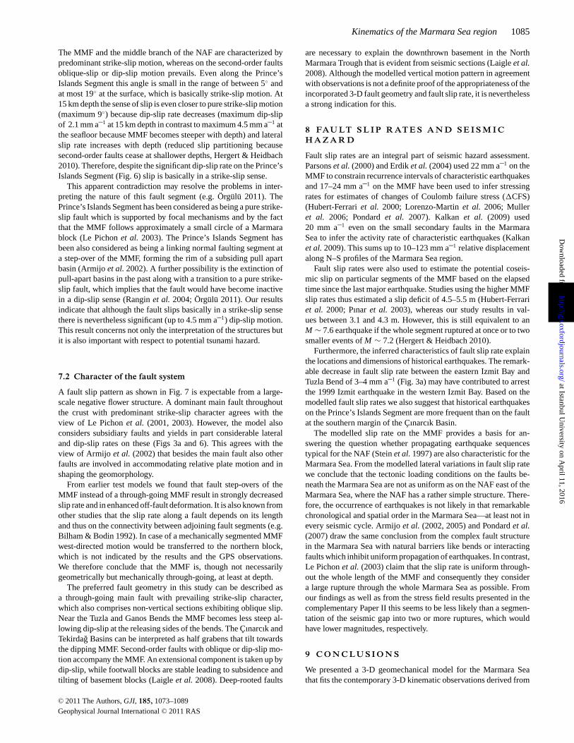
Figure 7. Absolute angle between a horizontal tangent at the fault and the 3-D slip-vector on the fault at the surface. Light colours correspond to strike-slipmotion and dark colours to dip-slip motion.
6.4 Areas of uplift
In comparison with the vertical velocities shown by Hergert & Hei-dbach (2010), there is no longer subsidence along the southern andwestern shore of the Marmara Sea, but uplift despite the exten-sional boundary conditions (Fig. 5). The reason is that herein the3-D (i.e. not only the horizontal but also the vertical) velocity fieldproduced by the regional model drives the Marmara model south ofthe NAF. Probably, the southwest turn of the middle and southernbranches of the NAF cause the uplift in the Strait of Canakkale area.In this way, the applied submodelling technique takes mechanismsfrom outside the model area into account that affect the model’sinterior.
A maximum uplift rate near the western shore of the MarmaraSea reaches 1.2 mm a–1. South of Izmit Bay between the northernand middle branches of the NAF and further to the south uplift ispredicted at rates of 0.1–0.4 mm a–1. The northern shelf and coastalarea to the north of the Central Segment of the MMF shows littleuplift of 0–0.2 mm a–1 and is basically stable.
The uplift to the west of the Marmara Sea has been attributedto the restraining Ganos Bend of the northern branch of the NAF(Seeber et al. 2004). Armutlu Peninsula and Samanlıda Massif havebeen interpreted to form a pressure ridge between the northern andmiddle branches of the NAF (Emre et al. 1998). Late Pleistocenemarine terraces have been documented at several places above thepresent sea level around the Marmara Sea indicating uplift (Fig. 5).Modelled uplift mostly correlates, both in location and rate, withthe location and uplift rates of these terraces, in particular along thewestern shore of the Marmara Sea and along the southern shore ofthe Izmit Bay (Fig. 5).
7 K I N E M AT I C S A N D FAU LTG E O M E T RY
From the presented results it becomes clear that fault geometriesstrongly affect the modelled kinematics. Here we show how thefault geometry in the Marmara Sea and the 3-D velocity field arerelated to each other.
Generally, the fault segments striking E–W to ENE–WSW slip atgreater rates than those oriented oblique to this orientation (Fig. 3a).Further, modelled slip rates depend on the length and depth extent(see Section 3.1.3) of a fault. If the lower ends of the smaller faultswere at greater depth than assumed, the slip rate on the MMF woulddecrease, whereas rates on the secondary faults would increase.Conversely, if the smaller faults would cease at shallower depths thanassumed, some fraction of the cumulative slip rate on these faultswould be additionally taken up by the MMF. However, this wouldnot explain markedly higher slip rates on the MMF because themodel with Byerlee coefficients of friction on the secondary faultsrepresents the extreme case with negligible slip on the secondaryfaults (Fig. 3d). If the secondary faults and the MMF would connectwith each other instead of being separated as assumed in the modelfor technical reasons then the effect of slip partitioning would begreater.
7.1 Sense of fault slip
To infer the sense of motion on the faults we calculate the absoluteangle between a horizontal tangent at the local fault plane and the3-D slip-vector on the fault (Fig. 7). We choose this representationrather than the rake because it is visually recognizable more easily.
C© 2011 The Authors, GJI, 185, 1073–1089
Geophysical Journal International C© 2011 RAS
at Istanbul University on A
pril 11, 2016http://gji.oxfordjournals.org/
Dow
nloaded from
Kinematics of the Marmara Sea region 1085
The MMF and the middle branch of the NAF are characterized bypredominant strike-slip motion, whereas on the second-order faultsoblique-slip or dip-slip motion prevails. Even along the Prince’sIslands Segment this angle is small in the range of between 5◦ andat most 19◦ at the surface, which is basically strike-slip motion. At15 km depth the sense of slip is even closer to pure strike-slip motion(maximum 9◦) because dip-slip rate decreases (maximum dip-slipof 2.1 mm a–1 at 15 km depth in contrast to maximum 4.5 mm a–1 atthe seafloor because MMF becomes steeper with depth) and lateralslip rate increases with depth (reduced slip partitioning becausesecond-order faults cease at shallower depths, Hergert & Heidbach2010). Therefore, despite the significant dip-slip rate on the Prince’sIslands Segment (Fig. 6) slip is basically in a strike-slip sense.
This apparent contradiction may resolve the problems in inter-preting the nature of this fault segment (e.g. Orgulu 2011). ThePrince’s Islands Segment has been considered as being a pure strike-slip fault which is supported by focal mechanisms and by the factthat the MMF follows approximately a small circle of a Marmarablock (Le Pichon et al. 2003). The Prince’s Islands Segment hasbeen also considered as being a linking normal faulting segment ata step-over of the MMF, forming the rim of a subsiding pull apartbasin (Armijo et al. 2002). A further possibility is the extinction ofpull-apart basins in the past along with a transition to a pure strike-slip fault, which implies that the fault would have become inactivein a dip-slip sense (Rangin et al. 2004; Orgulu 2011). Our resultsindicate that although the fault slips basically in a strike-slip sensethere is nevertheless significant (up to 4.5 mm a–1) dip-slip motion.This result concerns not only the interpretation of the structures butit is also important with respect to potential tsunami hazard.
7.2 Character of the fault system
A fault slip pattern as shown in Fig. 7 is expectable from a large-scale negative flower structure. A dominant main fault throughoutthe crust with predominant strike-slip character agrees with theview of Le Pichon et al. (2001, 2003). However, the model alsoconsiders subsidiary faults and yields in part considerable lateraland dip-slip rates on these (Figs 3a and 6). This agrees with theview of Armijo et al. (2002) that besides the main fault also otherfaults are involved in accommodating relative plate motion and inshaping the geomorphology.
From earlier test models we found that fault step-overs of theMMF instead of a through-going MMF result in strongly decreasedslip rate and in enhanced off-fault deformation. It is also known fromother studies that the slip rate along a fault depends on its lengthand thus on the connectivity between adjoining fault segments (e.g.Bilham & Bodin 1992). In case of a mechanically segmented MMFwest-directed motion would be transferred to the northern block,which is not indicated by the results and the GPS observations.We therefore conclude that the MMF is, though not necessarilygeometrically but mechanically through-going, at least at depth.
The preferred fault geometry in this study can be described asa through-going main fault with prevailing strike-slip character,which also comprises non-vertical sections exhibiting oblique slip.Near the Tuzla and Ganos Bends the MMF becomes less steep al-lowing dip-slip at the releasing sides of the bends. The Cınarcık andTekirdag Basins can be interpreted as half grabens that tilt towardsthe dipping MMF. Second-order faults with oblique or dip-slip mo-tion accompany the MMF. An extensional component is taken up bydip-slip, while footwall blocks are stable leading to subsidence andtilting of basement blocks (Laigle et al. 2008). Deep-rooted faults
are necessary to explain the downthrown basement in the NorthMarmara Trough that is evident from seismic sections (Laigle et al.2008). Although the modelled vertical motion pattern in agreementwith observations is not a definite proof of the appropriateness of theincorporated 3-D fault geometry and fault slip rate, it is neverthelessa strong indication for this.
8 FAU LT S L I P R AT E S A N D S E I S M I CH A Z A R D
Fault slip rates are an integral part of seismic hazard assessment.Parsons et al. (2000) and Erdik et al. (2004) used 22 mm a–1 on theMMF to constrain recurrence intervals of characteristic earthquakesand 17–24 mm a–1 on the MMF have been used to infer stressingrates for estimates of changes of Coulomb failure stress (�CFS)(Hubert-Ferrari et al. 2000; Lorenzo-Martin et al. 2006; Mulleret al. 2006; Pondard et al. 2007). Kalkan et al. (2009) used20 mm a–1 even on the small secondary faults in the MarmaraSea to infer the activity rate of characteristic earthquakes (Kalkanet al. 2009). This sums up to 10–123 mm a–1 relative displacementalong N–S profiles of the Marmara Sea region.
Fault slip rates were also used to estimate the potential coseis-mic slip on particular segments of the MMF based on the elapsedtime since the last major earthquake. Studies using the higher MMFslip rates thus estimated a slip deficit of 4.5–5.5 m (Hubert-Ferrariet al. 2000; Pınar et al. 2003), whereas our study results in val-ues between 3.1 and 4.3 m. However, this is still equivalent to anM ∼ 7.6 earthquake if the whole segment ruptured at once or to twosmaller events of M ∼ 7.2 (Hergert & Heidbach 2010).
Furthermore, the inferred characteristics of fault slip rate explainthe locations and dimensions of historical earthquakes. The remark-able decrease in fault slip rate between the eastern Izmit Bay andTuzla Bend of 3–4 mm a–1 (Fig. 3a) may have contributed to arrestthe 1999 Izmit earthquake in the western Izmit Bay. Based on themodelled fault slip rates we also suggest that historical earthquakeson the Prince’s Islands Segment are more frequent than on the faultat the southern margin of the Cınarcık Basin.
The modelled slip rate on the MMF provides a basis for an-swering the question whether propagating earthquake sequencestypical for the NAF (Stein et al. 1997) are also characteristic for theMarmara Sea. From the modelled lateral variations in fault slip ratewe conclude that the tectonic loading conditions on the faults be-neath the Marmara Sea are not as uniform as on the NAF east of theMarmara Sea, where the NAF has a rather simple structure. There-fore, the occurrence of earthquakes is not likely in that remarkablechronological and spatial order in the Marmara Sea—at least not inevery seismic cycle. Armijo et al. (2002, 2005) and Pondard et al.(2007) draw the same conclusion from the complex fault structurein the Marmara Sea with natural barriers like bends or interactingfaults which inhibit uniform propagation of earthquakes. In contrast,Le Pichon et al. (2003) claim that the slip rate is uniform through-out the whole length of the MMF and consequently they considera large rupture through the whole Marmara Sea as possible. Fromour findings as well as from the stress field results presented in thecomplementary Paper II this seems to be less likely than a segmen-tation of the seismic gap into two or more ruptures, which wouldhave lower magnitudes, respectively.
9 C O N C LU S I O N S
We presented a 3-D geomechanical model for the Marmara Seathat fits the contemporary 3-D kinematic observations derived from
C© 2011 The Authors, GJI, 185, 1073–1089
Geophysical Journal International C© 2011 RAS
at Istanbul University on A
pril 11, 2016http://gji.oxfordjournals.org/
Dow
nloaded from
1086 T. Hergert et al.
GPS, geological and geomorphological data. From our results weconclude:
(1) The 3-D kinematic results fit the model-independent obser-vations, from timescales which range from interseismic periods(GPS) to several thousand years (fault slip rates from geologicaland palaeoseismological data and geomorphologic constraints).
(2) Although the MMF accounts for the dominant part of relativeAnatolia–Eurasia plate motion (12.8–17.8 mm a–1), relative platemotion in the Marmara Sea region has to be distinguished fromthe slip rate on the MMF. Second-order faults, dip-slip and internaldeformation contribute to the relative plate motion.
(3) The modelled uplift and subsidence rates largely coincidewith both, the observed pattern and rates. The present morphologyis reflected by the modelled vertical motion, which suggests thattectonic processes have been important in shaping the seafloor. Themodelled characteristics of the subsidence in the basins suggest thatthe implemented fault geometry is reasonable, that is, asymmetrichalf grabens bounded by a dominating through-going MMF on oneside and synthetic normal faults on the other. Vertical motion is toa large extent fault controlled.
(4) As available geodetic constraints may be met by differentmodels of different fault geometries and fault slip distributions it isimportant to ensure appropriate fault geometries and representationof the kinematics, that is, allowing for internal deformation anddynamically consistent fault slip. Discrepancies between geologicaland geodetic fault slip rates can be due to this issue.
(5) We find that the post-seismic signal from the 1912 and 1894earthquakes is negligible in the decade before the 1999 Izmit earth-quake.
(6) In contrast to the 3-D fault geometry, material propertieshave little influence on the kinematics. A dislocation model usingthe boundary element method would probably result in a similarkinematics. However, for the dynamic model results material prop-erties play a major role (see complementary Paper II).
In the complementary Paper II we will show that the 3-D stressstate of this model widely fits also the stress observations in theMarmara Sea. This would imply that our overall goal to constructa model that is consistent with both, kinematic and dynamic obser-vations is attained. The presented model concept can be transferredto other strike-slip regions where complex 3-D fault systems takeup relative plate motion.
A C K N OW L E D G M E N T S
In particular, we thank A. Hirn for very fruitful discussions on the3-D kinematics of the Marmara Sea fault system. We also thank K.Fuchs and F. Wenzel for helpful suggestions. We thank the editorDuncan Agnew and two anonymous reviewers for their commentsand suggestions. This work was supported by the CEDIM Projectat Universitat Karlsruhe (TH) and GFZ German Research Centrefor Geosciences, by the Heidelberg Academy of Sciences and Hu-manities and by the Task Force VII ‘Temporal and Spatial Changesof Stress and Strain’ of the International Lithosphere Program.
R E F E R E N C E S
Aksoy, M.E., Meghraoui, M., Ferry, M., Cakir, Z., Akyuz, S., Karabacak,V. & Altunel, E., 2006. Fault characteristics, segmentation and pa-leoseismology along the 9 August 1912 Ganos earthquake-rupture(North Anatolian Fault, Turkey), Geophys. Res. Abs., 8, SRef-ID: 1607-7962/gra/EGU1606-10002.
Aksu, A.E., Calon, T.J., Hiscott, R.N. & Yasar, D., 2000. Anatomy of theNorth Anatolian Fault Zone in the Marmara Sea, Western Turkey: exten-sional basins above a continental transform, GSA Today, 10(6), 3–7.
d’Alessio, M.A., Williams, C.F. & Burgmann, R., 2006. Frictional strengthheterogeneity and surface heat flow: implications for the strengthof the creeping San Andreas fault. J. geophys. Res, 111(B05410),doi:10.1029/2005JB003780.
Alpar, B. & Yaltırak, C., 2002. Characteristic features of the North AnatolianFault in the eastern Marmara region and its tectonic evolution, Mar. Geol.,190, 329–350, PII:S0025-3227(0002)00353-00355
Ambraseys, N., 2002. The seismic activity of the Marmara Sea region overthe last 2000 years, Bull. seism. Soc. Am., 92, 1–18.
Ambraseys, N., 2006. Comparison of frequency of occurrence of earth-qaukes with slip rates from long-term seismicity data: the cases of Gulfof Corinth, Sea of Marmara and Dead Sea Fault Zone, Geophys. J. Int.,165, 516–526.
Armijo, R., Meyer, B., Hubert, A. & Barka, A., 1999. Westward propaga-tion of the North Anatolian fault into the northern Aegean: timing andkinematics, Geology, 27, 267–270.
Armijo, R., Meyer, B., Navarro, S., King, G. & Barka, A., 2002. Asymmetricslip partitioning in the Sea of Marmara pull-apart: a clue to propagationprocesses of the North Anatolian Fault? Terra Nova, 13, 80–86.
Armijo, R., Flerit, F., King, G. & Meyer, B., 2003. Linear elastic fracturemechanics explains the past and present evolution of the Aegean, Earthplanet. Sci. Lett., 217, 85–95.
Armijo, R., et al., 2005. Submarine fault scarps in the Sea of Marmarapull-apart (North Anatolian Fault): implications for seismic hazard inIstambul, Geochem. Geophys. Geosyst., 6, doi:10.1029/2004GC000896.
Avsar, U. & Isseven, T., 2009. Regional clockwise rotation of the ArmutluPenisnula, Western Turkey, resolved from paleomagnetic study of Eocenevolcanics, Tectonophysics, 475, 415–422.
Ayhan, M.E., Demir, C., Lenk, O., Kilicogul, A., Altiner, Y., Barka, A.A.,Ergintav, S. & Ozener, H., 2002. Interseismic strain accumulation in theMarmara Sea Region, Bull. seism. Soc. Am., 92, 216–229.
Barka, A., 1997. Neotectonics of the Marmara region. in Active Tectonics ofNorthwestern Anatolia: The MARMARA Poly-Project, pp. 329–374, edsSchindler, C. & Pfister, M., vdf Hochschulverlag AG ETH, Zurich.
Barka, A.A. & Kadinsky-Cade, C., 1988. Strike-slip fault geometry inTurkey and its influence on earthquake activity, Tectonics, 7, 663–684.
Bayrakcı, G., 2009. Heterogeneite 3D de la croute superieure sous la Merde Marmara: tomographie sur une grille de sismometres fond de mer etde profils de tirs, PhD thesis, Institut de Physique du Globe de Paris.
Becel, A., et al., 2009. Moho, crustal architecture and deep deformationunder the North Marmara Trough, from the Seismarmara Leg1 offshore-onshore reflection-refraction survey, Tectonophysics, 467, 1–21.
Becel, A., Laigle, M., de Voogd, B., Hirn, A., Taymaz, T., Yolsal-Cevikbilen,S. & Shimamura, H., 2010. North Marmara Trough architecture of basininfill, basement and faults, from PSDM reflection and OBS refractionseismics, Tectonophysics, 490, 1–14.
Bilham, R. & Bodin, P, 1992. Fault zone connectivity: slip rates on faults inthe San Francisco Bay Area, California, Science, 258, 281–284.
Bird, P., 1998. Testing hypotheses on plate-driving mechanisms with globallithosphere models including topography, thermal structure, and faults, J.geophys. Res., 103(B5), 10 115–10 129.
Biryol, C.B., et al., 2008. NAF experiment: seismic anisotropy beneathNorthern Anatolia from shear-wave splitting, EOS, Trans. Am. geophys.Un., 89(53), Abstract T21A-1916.
Brocher, T.M., 2005. Empirical relations between elastic wavespeedsand density in the Earth’s crust, Bull. seism. Soc. Am., 95,doi:10.1785/0120050077.
Byerlee, J.D., 1978. Friction of rocks, Pure appl. Geophys., 116, 615–626.Cai, J. & Grafarend, E.W., 2007. Statistical analysis of geodetic deformation
(strain rate) derived from the space geodetic measurements of BIFROSTProject in Fennoscandia, J. Geodyn., 43, 214–238.
Carton, H., et al., 2007. Seismic imaging of the three-dimensional architec-ture of the Cınarcık Basin along the North Anatolian Fault, J. geophys.Res., 112, doi:10.1029/2006JB004548.
C© 2011 The Authors, GJI, 185, 1073–1089
Geophysical Journal International C© 2011 RAS
at Istanbul University on A
pril 11, 2016http://gji.oxfordjournals.org/
Dow
nloaded from
Kinematics of the Marmara Sea region 1087
Cormier, M.-H., et al., 2006. North Anatolian Fault in the Gulf of Izmit(Turkey): rapid vertical motion in response to minor bends of a nonverticalcontinental transform, J. geophys. Res, 111, doi:10.1029/2005JB003633.
Elmas, A., 2003. Late Cenozoic tectonics and stratigraphy of northwesternAnatolia: the effects of the North Anatolian Fault to the region, Int. J. EarthSci. (Geol. Rundschau), 92, 380–396, doi:10.1007/s00531-003-0322-2.
Elmas, A. & Yigitbas, E., 2001. Ophiolite emplacement by strike-slip tec-tonics between the Pontide Zone and the Sakarya Zone in northwesternAnatolia, Turkey, Int. J. Earth Sci. (Geol Rundschau), 90, 257–269, doi:10.1007/s005310000129.
Emre, O., Erkal, T., Tchepalyga, A., Kazancı, N., Kecer, M. & Unay, E.,1998. Neogene-Quaternary evolution of the eastern Marmara region,northwest Turkey, Minerol. Res. Expl. Bull., 120, 119–145.
Emre, O., Ozaksoy, V. & Cagatay, N. 2006. Guide Book. Field Trip to theNorth Anatolian Fault System Between Izmit and Yalova, in InternationalWorkshop in Comparative Studies of the North Anatolian Fault and theSan Andreas Fault, 2006 August 14–18, Istanbul.
Erdik, M., Demircioglu, M., Sesetyan, K., Durukal, E. & Siyahi, B., 2004.Earthquake hazard in Marmara Region, Turkey, Soil Dyn. Earthq. Eng.,24, 605–631.
Ergun, M. & Ozel, E., 1995. Structural relationship between the Sea ofMarmara Basin and the North Anatolian Fault Zone, Terra Nova, 7,278–288.
Eyidogan, H., 1988. Rates of crustal deformation in western Turkey asdeduced from major earthquakes, Tectonophysics, 148, 83–92.
Flerit, F., Armijo, R., King, G. & Meyer, B., 2004. The mechanical in-teraction between the propagating North Anatolian Fault and the back-arc extension in the Aegean, Earth planet. Sci. Lett., 224, 347–362,doi:10.1016/j.epsl.2004.05.028.
Geist, E.L. & Andrews, D.J., 2000. Slip rates on San Fransico Bay area faultsfrom anelastic deformation of the continental lithosphere. J. geophys. Res,105, B11, 25543–25552.
Gomez, F., et al., 2007. Global Positioning System measurements ofstrain accumulation and slip transfer through the restraining bend alongthe Dead Sea fault system in Lebanon, Gephys. J. Int., 168, 1021–1028.
Hatzfeld, D., et al., 2001. Shear wave anisotropy in the upper mantle be-neath the Aegean related to internal deformation, J. geophys. Res., 106,30737–30753.
Heidbach, O. & Drewes, H., 2003. 3-D finite element model of ma-jor tectonic processes in the Eastern Mediterranean, in New insightsin Structural Interpretation and Modelling, Geol. Soc. Spec. Pub. Vol.212, pp. 261–274, ed. Nieuwland, D., Geological Society, London,doi.10.1144/GSL.SP.2003.212.01.17.
Hergert, T. & Heidbach, O., 2010. Slip-rate variability and distributed de-formation in the Marmara Sea fault system, Nat. Geosci., 3, 132–135,doi:10.1038/NGEO739.
Hergert, T. & Heidbach, O., 2011. Geomechanical model of the Mar-mara Sea region—II. 3D contemporary background stress field, Geo-phys. J. Int., in press, doi:10.1111/j.1365-246X.2011.04992.x. (this issue)(Paper II).
Hubert-Ferrari, A., Barka, A., Jacques, E., Nalbant, S., Meyer, B., Armijo,R., Tapponier, P. & King, G.C.P., 2000. Seismic hazard in the MarmaraSea region following the 17 August 1999 Izmit earthquake, Nature, 404,269–271.
Hubert-Ferrari, A., Armijo, R., King, G., Mayer, B. & Barka, A., 2002.Morphology, displacement, and slip rates along the North Anatolian Fault,Turkey, J. geophys. Res, 107, B10, 2235, doi:10.1029/2001JB000393.
Hubert-Ferrari, A., King, G., Manighetti, I., Armijo, R., Meyer, B. &Tapponnier, P., 2003. Long-term elasticity in the continental litosphere:modelling the Aden Ridge propagation and the Anatolian extrusion pro-cess, Geophys. J. Int., 153, 111–132.
Jackson, J. & McKenzie, D., 1984. Active tectonics of the Alpine-HimalayanBelt between western Turkey and Pakistan, Geophys. J. R. astr., 77,185–264.
Jamison, D.B. & Cook, N.G.W., 1980. Note on measured values for the stateof stress in the Earth’s crust, J. geophys. Res, 85, 1833–1838.
Jimenez-Munt, I. & Sabadini, R., 2002. The block-like behavior of Anatolia
envisaged in the modeled and geodetic strain rates, Geophys. Res. Lett.,29, 1978, doi:10.1029/2002GL015995.
Jones, C.H. & Wesnousky, S.G., 1992. Variations in strength and slip ratealong the San Andreas fault system, Science, 256, 83–86.
Kalkan, E., Gulkan, P., Yılmaz, N. & Celebi, M., 2009. Reassessment ofprobabilistic seismic hazard in the Marmara region, Bull. seism. Soc.Am., 99, 4, 2127–2146, doi:10.1785/0120080285.
Kanbur, Z., Alptekin, O., Utkucu, M. & Kanbur, S., 2007. Imaging thebasin and fault geometry from the multichannel seismic reflection data inthe Tekirdag Basin, Marmara Sea, Turkey, Geophys. J. Int, 169, 659–666doi:10.1111/j.1365-1246X.2007.03356.x.
Kiratzi, A., 1993. A study on the active crustal deformation of the Northand East Anatolian Fault Zones, Tectonophysics, 225, 191–203.
Kiratzi, A.A. & Papazachos, C.B., 1995. Active crustal deformation fromthe Azores triple junction to the Middle East, Tectonophysics, 243,1–24.
Koral, H., 2007. Modes, rates and geomorphological consequences of ac-tive tectonics in the Marmara Region, NW Turkey: a critical overviewbased on seismotectonic field observations, Quat. Int., 167–168, 149–161,doi:10.1016/j.quaint.2007.02.1023.
Kozacı, O., Dolan, J.F., Finkel, R. & Hartleb, R., 2007. Late Holoceneslip rate for the North Anatolian fault, Turkey, from cosmogenic 36Clgeochronology: implications for the constancy of fault loading and strainrelease rates, Geology, 35, 867–870, doi:10.1130/G23187A.23181.
Kozacı, O., Dolan, J.F. & Finkel, R.C., 2009. A Late Holocene slip rate for thecentral North Anatolian fault, at Tahtakopru, Turkey, from cosmogenic10Be geochronology: implications for fault loading and strain releaserates, J. geophys. Res., 114, B01405, doi:10.1029/2008JB005760.
Kurcer, A., Chatzipetros, A., Tutkun, S.Z., Pavlides, S., Ate, O. & Valka-niotis, S., 2008. The Yenice–Gonen active fault (NW Turkey): ac-tive tectonics and palaeoseismology, Tectonophysics, 453, 263–275,doi:10.1016/j.tecto.2007.07.010.
Kurtulus, C. & Canbay, M.M., 2007. Tracing the middle strand of the NorthAnatolian Fault Zone through the southern Sea of Marmara based onseismic reflection studies, Geo-Mar Lett., 27, 27–40, doi:10.1007/s00367-006-0050-2.
Laigle, M., Becel, A., de Voogd, B., Hirn, A., Taymaz, T., Ozalaybey, S.& Team, S.L., 2008. A first deep seismic survey in the Sea of Marmara:deep basins and whole crust architecture and evolution, Earth planet. Sci.Lett., 270, 168–179.
Le Pichon, X., Chamot-Rooke, N., Lallemant, S., Noomen, R. & Veis,G., 1995. Geodetic determination of kinematics of Central Greece withrespect to Europe: implications for Eastern Mediterranean, J. geophys.Res., 100, 12675–12690.
Le Pichon, X., et al., 2001. The active main Marmara fault, Earth planet.Sci. Lett., 192, 595–616.
Le Pichon, X.L., Chamot-Rooke, A., Rangin, C. & Sengor, A.M.C., 2003.The North Anatolian fault in the Sea of Marmara, J. geophys. Res., 108,doi:10.1029/2002JB001862.
Lorenzo-Martin, F., Roth, F. & Wang, R., 2006. Elastic and inelastic trig-gering of earthquakes in the North Anatolian Fault zone, Tectonophysics,424(3–4), 271–289, doi:10.1016/j.tecto.2006.03.046.
Mayer, L. & Lu, Z., 2001. Elastic rebound following the Kocaeli earthquake,Turkey, recorded using synthetic aperture radar interferometry, Geology,29, 6, 495–498.
McClusky, S., et al., 2000. Global Positioning System constraints on platekinematics and dynamics in the eastern Mediterranean and Caucasus, J.geophys. Res., 105, 5695–5719.
McHugh, C.M.G., Seeber, L., Cormier, M.-H., Dutton, J., Cagatay, N.,Polonia, A., Ryan, W.B.F. & Gorur, N., 2006. Submarine earthquakegeology along the North Anatolia Fault in the Marmara Sea, Turkey: amodel for transform basin sedimentation, Earth planet. Sci. Lett., 248,661–684, doi:10.1016/j.epsl.2006.05.038.
McKenzie, D., 1972. Active tectonics of the Mediterranean region, Geophys.J. R. astr. Soc., 30, 109–185.
Meade, B.J., Hager, B.H., McClusky, S.C., Reilinger, R., Ergintav, S., Lenk,O., Barka, A. & Ozener, H., 2002. Estimates of seismic potential inthe Marmara Sea region from block models of secular deformation
C© 2011 The Authors, GJI, 185, 1073–1089
Geophysical Journal International C© 2011 RAS
at Istanbul University on A
pril 11, 2016http://gji.oxfordjournals.org/
Dow
nloaded from
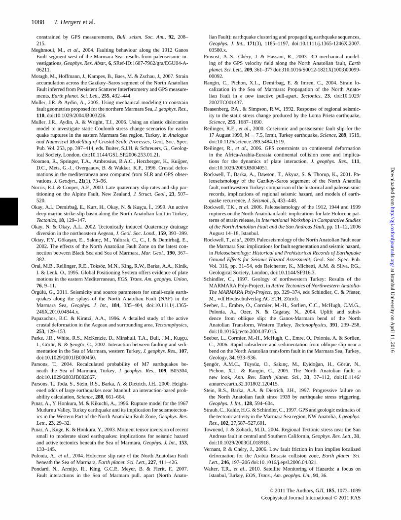
1088 T. Hergert et al.
constrained by GPS measurements, Bull. seism. Soc. Am., 92, 208–215.
Meghraoui, M., et al., 2004. Faulting behaviour along the 1912 GanosFault segment west of the Marmara Sea: results from paleoseismic in-vestigations, Geophys. Res. Abstr., 6, SRef-ID:1607-7962/gra/EGU04-A-06211.
Motagh, M., Hoffmann, J., Kampes, B., Baes, M. & Zschau, J., 2007. Strainaccumulation across the Gazikoy–Saros segment of the North AnatolianFault inferred from Persistent Scatterer Interferometry and GPS measure-ments, Earth planet. Sci. Lett., 255, 432–444.
Muller, J.R. & Aydin, A., 2005. Using mechanical modeling to constrainfault geometries proposed for the northern Marmara Sea, J. geophys. Res.,110, doi:10.1029/2004JB003226.
Muller, J.R., Aydin, A. & Wright, T.J., 2006. Using an elastic dislocationmodel to investigate static Coulomb stress change scenarios for earth-quake ruptures in the eastern Marmara Sea region, Turkey, in Analogueand Numerical Modelling of Crustal-Scale Processes, Geol. Soc. Spec.Pub. Vol. 253, pp. 397–414, eds. Buiter, S.J.H. & Schreuers, G., Geolog-ical Society, London, doi:10.1144/GSL.SP.2006.253.01.21.
Noomen, R., Springer, T.A., Ambrosius, B.A.C., Herzberger, K., Kuijper,D.C., Mets, G.-J., Overgaauw, B. & Wakker, K.F., 1996. Crustal defor-mations in the mediterranean area computed from SLR and GPS obser-vations, J. Geodyn., 21(1), 73–96.
Norris, R.J. & Cooper, A.F., 2000. Late quaternary slip rates and slip par-titioning on the Alpine Fault, New Zealand, J. Struct. Geol., 23, 507–520.
Okay, A.I., Demirbag, E., Kurt, H., Okay, N. & Kuscu, I., 1999. An activedeep marine strike-slip basin along the North Anatolian fault in Turkey,Tectonics, 18, 129–147.
Okay, N. & Okay, A.I., 2002. Tectonically induced Quaternary drainagediversion in the northeastern Aegean, J. Geol. Soc. Lond., 159, 393–399.
Oktay, F.Y., Gokasan, E., Sakınc, M., Yaltırak, C., C., I. & Demirbag, E.,2002. The effects of the North Anatolian Fault Zone on the latest con-nection between Black Sea and Sea of Marmara, Mar. Geol., 190, 367–382.
Oral, M.B., Reilinger, R.E., Toksoz, M.N., King, R.W., Barka, A.A., Kinik,I. & Lenk, O., 1995. Global Positioning System offers evidence of platemotions in the eastern Mediterranean, EOS, Trans. Am. geophys. Union,76, 9–11.
Orgulu, G., 2011. Seismicity and source parameters for small-scale earth-quakes along the splays of the North Anatolian Fault (NAF) in theMarmara Sea, Geophys. J. Int., 184, 385–404, doi:10.1111/j.1365-246X.2010.04844.x.
Papazachos, B.C. & Kiratzi, A.A., 1996. A detailed study of the activecrustal deformation in the Aegean and surrounding area, Tectonophysics,253, 129–153.
Parke, J.R., White, R.S., McKenzie, D., Minshull, T.A., Bull, J.M., Kuscu,I., Gorur, N. & Sengor, C., 2002. Interaction between faulting and sedi-mentation in the Sea of Marmara, western Turkey, J. geophys. Res., 107,doi:10.1029/2001JB000450.
Parsons, T., 2004. Recalculated probability of M7 earthquakes be-neath the Sea of Marmara, Turkey, J. geophys. Res., 109, B05304,doi:10.1029/2003JB002667.
Parsons, T., Toda, S., Stein, R.S., Barka, A. & Dietrich, J.H., 2000. Height-ened odds of large earthquakes near Istanbul: an interaction-based prob-ability calculation, Science, 288, 661–664.
Pınar, A., Y. Honkura, M. & Kikuchi, A., 1996. Rupture model for the 1967Mudurnu Valley, Turkey earthquake and its implication for seismotecton-ics in the Western Part of the North Anatolian Fault Zone, Geophys. Res.Lett., 23, 29–32.
Pınar, A., Kuge, K. & Honkura, Y., 2003. Moment tensor inversion of recentsmall to moderate sized earthquakes: implications for seismic hazardand active tectonics beneath the Sea of Marmara, Geophys. J. Int., 153,133–145.
Polonia, A., et al., 2004. Holocene slip rate of the North Anatolian Faultbeneath the Sea of Marmara, Earth planet. Sci. Lett., 227, 411–426.
Pondard, N., Armijo, R., King, G.C.P., Meyer, B. & Flerit, F., 2007.Fault interactions in the Sea of Marmara pull. apart (North Anato-
lian Fault): earthquake clustering and propagating earthquake sequences,Geophys. J. Int., 171(3), 1185–1197, doi:10.1111/j.1365-1246X.2007.03580.x.
Provost, A.-S., Chery, J. & Hassani, R., 2003. 3D mechanical model-ing of the GPS velocity field along the North Anatolian fault, Earthplanet. Sci. Lett., 209, 361–377 doi:310.1016/S0012-1821X(1003)00099-00092.
Rangin, C., Pichon, X.L., Demirbag, E. & Imren, C., 2004. Strain lo-calization in the Sea of Marmara: Propagation of the North Anato-lian Fault in a now inactive pull-apart, Tectonics, 23, doi:10.1029/2002TC001437.
Reasenberg, P.A., & Simpson, R.W., 1992. Response of regional seismic-ity to the static stress change produced by the Loma Prieta earthquake,Science, 255, 1687–1690.
Reilinger, R.E., et al., 2000. Coseismic and postseismic fault slip for the17 August 1999, M = 7.5, Izmit, Turkey earthquake, Science, 289, 1519,doi:10.1126/science.289.5484.1519.
Reilinger, R., et al., 2006. GPS constraints on continental deformationin the Africa-Arabia-Eurasia continental collision zone and implica-tions for the dynamics of plate interaction, J. geophys. Res., 111,doi:10.1029/2005JB004051.
Rockwell, T., Barka, A., Dawson, T., Akyuz, S. & Thorup, K., 2001. Pa-leoseismology of the Gazikoy-Saros segement of the North Anatoliafault, northwestern Turkey: comparison of the historical and paleoseismicrecords, implications of regional seismic hazard, and models of earth-quake recurrence, J. Seismol., 5, 433–448.
Rockwell, T.K., et al. 2006. Paleoseismology of the 1912, 1944 and 1999ruptures on the North Anatolian fault: implications for late Holocene pat-terns of strain release, in International Workshop in Comparative Studiesof the North Anatolian Fault and the San Andreas Fault, pp. 11–12, 2006August 14–18, Istanbul.
Rockwell, T., et al., 2009. Paleoseismology of the North Anatolian Fault nearthe Marmara Sea: implications for fault segmentation and seismic hazard,in Paleoseismology: Historical and Prehistorical Records of EarthquakeGround Effects for Seismic Hazard Assessment, Geol. Soc. Spec. Pub.Vol. 316, pp. 31–54, eds Reicherter, K., Michetti, A.M. & Silva, P.G.,Geological Society, London, doi:10.1144/SP316.3.
Schindler, C., 1997. Geology of northwestern Turkey: Results of theMARMARA Poly-Project, in Active Tectonics of Northwestern Anatolia-The MARMARA Poly-Project, pp. 329–374, eds Schindler, C. & Pfister,M., vdf Hochschulverlag AG ETH, Zurich.
Seeber, L., Embre, O., Cormier, M.-H., Sorlien, C.C., McHugh, C.M.G.,Polonia, A., Ozer, N. & Cagatay, N., 2004. Uplift and subsi-dence from oblique slip: the Ganos-Marmara bend of the NorthAnatolian Transform, Western Turkey, Tectonophysics, 391, 239–258,doi:10.1016/j.tecto.2004.07.015.
Seeber, L., Cormier, M.-H., McHugh, C., Emre, O., Polonia, A. & Sorlien,C., 2006. Rapid subsidence and sedimentation from oblique slip near abend on the North Anatolian transform fault in the Marmara Sea, Turkey,Geology, 34, 933–936.
Sengor, A.M.C., Tuysuz, O., Sakınc, M., Eyidogan, H., Gorur, N.,Pichon, X.L. & Rangin, C., 2005. The North Anatolian fault: anew look, Ann. Rev. Earth planet. Sci., 33, 37–112, doi:10.1146/annurev.earth.32.101802.120415.
Stein, R.S., Barka, A.A. & Dietrich, J.H., 1997. Progressive failure onthe North Anatolian fault since 1939 by earthquake stress triggering,Geophys. J. Int., 128, 594–604.
Straub, C., Kahle, H.G. & Schindler, C., 1997. GPS and geologic estimates ofthe tectonic activity in the Marmara Sea region, NW Anatolia, J. geophys.Res., 102, 27,587–527,601.
Townend, J. & Zoback, M.D., 2004. Regional Tectonic stress near the SanAndreas fault in central and Southern California, Geophys. Res. Lett., 31,doi:10.1029/2003GL018918.
Vernant, P. & Chery, J., 2006. Low fault friction in Iran implies localizeddeformation for the Arabia–Eurasia collision zone, Earth planet. Sci.Lett., 246, 197–206 doi:10.1016/j.epsl.2006.04.021.
Walter, T.R., et al., 2010. Satellite Monitoring of Hazards: a focus onIstanbul, Turkey, EOS, Trans., Am. geophys. Un., 91, 36.
C© 2011 The Authors, GJI, 185, 1073–1089
Geophysical Journal International C© 2011 RAS
at Istanbul University on A
pril 11, 2016http://gji.oxfordjournals.org/
Dow
nloaded from
Kinematics of the Marmara Sea region 1089
Westaway, R., 1994. Present-day kinematics of the Middle East and easternMediterranean, J. geophys. Res., 99, 12 071–12 090.
Yaltırak, C. & Alpar, B. 2002a. Kinematics and evolution of the north-ern branch of the North Anatolian Fault (Ganos Fault) between theSea of Marmara and the Gulf of Saros, Mar. Geol., 190, 351–366.
Yaltırak, C. & Alpar, B. 2002b. Evolution of the middle strand ofthe North Anatolian Fault and shallow seismic investigation of thesoutheastern Marmara Sea (Gemlik Bay), Mar. Geol., 190, 307–327.
Yaltırak, C., Sakinc, M., Aksu, A.E., Hiscott, R.N., Galleb, B. & Ulgen, U.B.,2002. Late Pleistocene uplift history along the southwestern Marmara Seadetermined from raised coastal deposits and global sea-level variations,Mar. Geol., 190, 283–305, PII:S0025-3227(02)00351-1.
Zienkiewicz, O.C. & Tayler, R.L., 1994. The Finite Element Method,Volume 1: Basic Formulations and Linear Problems, 4th edn, McGrawHill, London.
Zoback, M.D., et al., 1987. New evidence of the state of stress of the SanAndreas fault system, Science, 238, 1105–1111.
S U P P O RT I N G I N F O R M AT I O N
Supporting Information may be found in the online version of thisarticle.
The following figures are included in the file namedgji 4991 sm supplement.pdf:
Figure S1. Moho map.Figure S2. MAT grad rock property distribution.Figure S3. Interseismic velocities and postseismic effects.Figure S4. Slip rates from previous models.
The geometry of the model along with a readme file is containedin ‘geometry.zip’.
Please note: Wiley-Blackwell are not responsible for the contentor functionality of any supporting materials supplied by the authors.Any queries (other than missing material) should be directed to thecorresponding author for the article.
C© 2011 The Authors, GJI, 185, 1073–1089
Geophysical Journal International C© 2011 RAS
at Istanbul University on A
pril 11, 2016http://gji.oxfordjournals.org/
Dow
nloaded from