Embed Size (px)
Citation preview
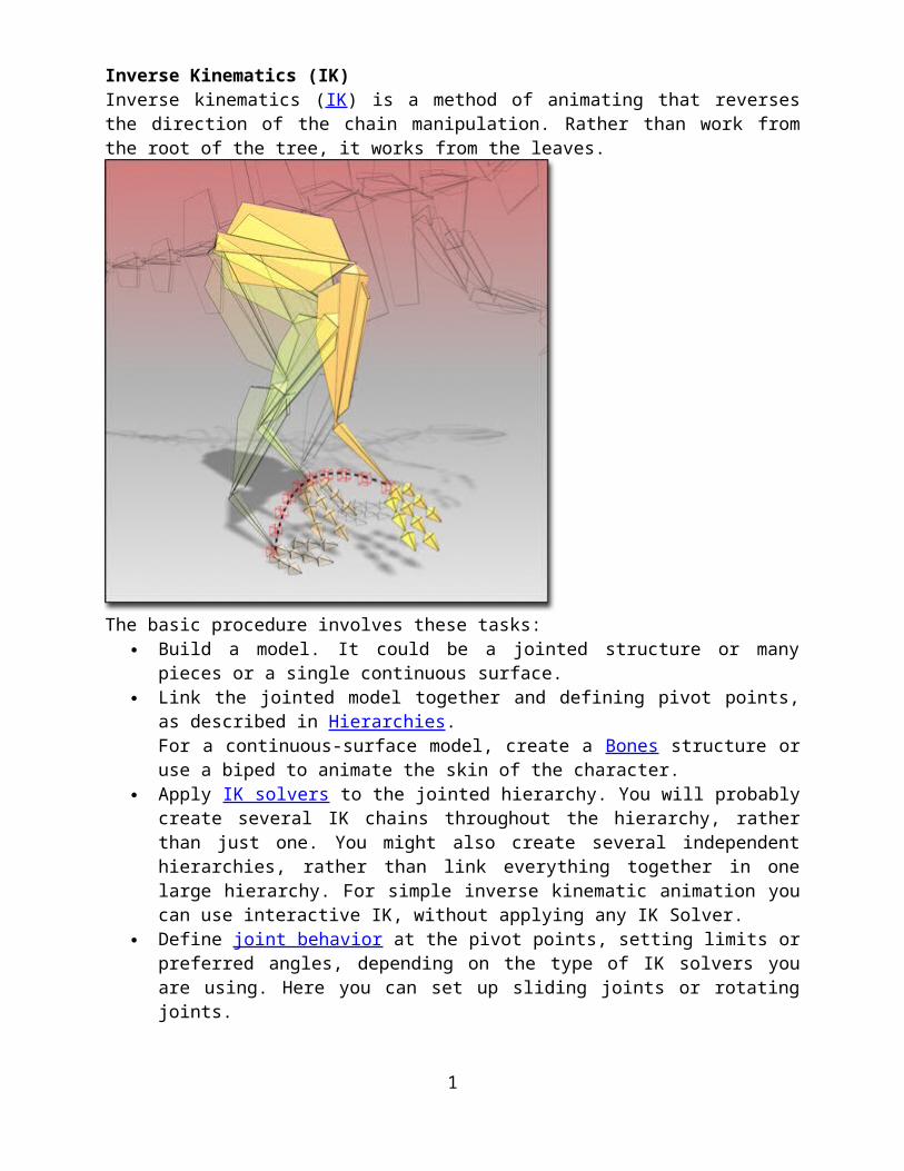
Inverse Kinematics (IK)Inverse kinematics (IK) is a method of animating that reverses the direction of the chain manipulation. Rather than work from the root of the tree, it works from the leaves.
The basic procedure involves these tasks: Build a model. It could be a jointed structure or many pieces or a single continuous
surface. Link the jointed model together and defining pivot points, as described in Hierarchies.
For a continuous-surface model, create a Bones structure or use a biped to animate the skin of the character.
Apply IK solvers to the jointed hierarchy. You will probably create several IK chains throughout the hierarchy, rather than just one. You might also create several independent hierarchies, rather than link everything together in one large hierarchy. For simple inverse kinematic animation you can use interactive IK, without applying any IK Solver.
Define joint behavior at the pivot points, setting limits or preferred angles, depending on the type of IK solvers you are using. Here you can set up sliding joints or rotating joints. You might also need to move the root of the hierarchy, and you might want to add control objects such as dummies or points at this point.
Animate the goal (in the case of an HI Solver or IK Limb solver) or the end effector (in the case of the HD Solver). This animates all the components of the IK chain. You can apply constraints to the goals or control objects or to the root of a chain.
You can externally reference IK chains in your scene. An XRef IK chain behaves the same as a non-XRef chain, except that you cannot retarget its XRef controller once it is in your master scene. Control Objects to Assist IK You can link a goal or an end effector to points, splines, or dummy objects that serve as quick controls to translate or rotate the end of the chain. These control objects can be linked together as
1

well, or they can be controlled with constraints. You can also use parameter wiring to build relationships between these control objects. You can wire control objects to manipulator helpers or to custom attributes, creating an easily accessible interface for your animatable model. You can add further controls to manipulate the elements in the middle of the chain. In the HI Solver, the swivel angle has its own manipulator, which can be animated or linked to another target object. Differences Between Forward and Inverse Kinematics Forward kinematics uses a top-down method, where you begin by positioning and rotating parent objects and work down the hierarchy positioning and rotating each child object. Basic principles of forward kinematics include:
Hierarchical linking from parent to child. Pivot points defining joints between objects. Children inheriting the transforms of their parents.
These principles are fairly forgiving. As long as everything is linked together and the pivots are located at joint locations, you can successfully animate the structure. Inverse kinematics (IK) uses a goal-directed method, where you position a goal object and 3ds Max calculates the position and orientation of the end of the chain. The final position of the hierarchy, after all of the calculations have been solved, is called the IK solution. There are a variety of IK solvers that can be applied to a hierarchy. Inverse kinematics starts with linking and pivot placement as its foundation and then adds the following principles:
Joints can be limited with specific positional and rotational properties. Position and orientation of parent objects are determined by the position and orientation
of child objects.Because of these additions, IK requires greater thought about how you link your objects and place pivots. Where many different solutions for linking objects may be suitable for forward kinematics, there are usually just a few good solutions for any given IK approach. Inverse kinematics is often easier to use than forward kinematics, and you can quickly create complex motions. If you need to edit those motions later, it can be simpler to revise the animation if you are using IK. It also is the best way to simulate weight in an animation. Inverse Kinematics MethodsInverse kinematics builds on the concepts of hierarchical linking. To understand how IK works, you must first understand the principles of hierarchical linking and forward kinematics. See Animating with Forward Kinematics and Inverse Kinematics (IK). IK Solvers IK solvers are specialized controllers that apply IK solutions procedurally across a range of frames. Four different IK solvers ship with 3ds Max:
HD (History-Dependent) HI (History-Independent) IK Limb Spline IK
In order to put an IK solver on a two-bone chain, a third bone is needed. Choose the first bone, then from the Create menu click IK solver, then click the third bone in the viewport. In general, all IK solvers:
Work on any hierarchy. Work on any hierarchy or bone structure. Calculate IK solutions for all frames in real-time as you make changes.
2

Allow you to create multiple IK chains within a single hierarchy. Allow you to create multiple or overlapping IK chains within a single hierarchy. Display active joint axes and joint limits graphically. Use a node, goal or an end effector to animate the end of a chain. Use an end effector to animate the end of a chain.
An IK solver places keyframes only on the IK goal or end effector, as opposed to forward kinematics (or the non-solver IK methods), which place rotation keyframes on the bones or hierarchical objects themselves. IK SolversSelect an object in a hierarchy where you want IK to start. Animation menu IK Solver Apply an IK solver. Click the object in the hierarchy where you want the IK chain to end. An IK solver creates an inverse kinematic solution to rotate and position links in a chain. It applies an IK Controller to govern the transforms of the children in a linkage. You can apply an IK solver to any hierarchy of objects. You apply an IK solver to a hierarchy or part of a hierarchy using commands on the Animation menu. Select an object in the hierarchy, choose an IK solver, and then click another object in the hierarchy to define the end of the IK chain.
Bones system with HI IK solver appliedEach type of IK solver has its own behavior and workflow, as well as its own specialized controls and tools that display in the Hierarchy and Motion panels. IK solvers are plug-ins, so programmers can expand IK capabilities of 3ds Max by customizing or writing their own IK solvers. 3ds Max ships with four different IK solvers. How Does an IK Solver Work? An IK solver generally operates in this way: an inverse kinematic chain is defined on part of the hierarchy, say from the hip to the heel, or the shoulder to the wrist of a character. At the end of the IK chain is a gizmo, called the goal. The goal can be repositioned or animated over time in a variety of ways, often using linkage, parameter wiring or constraints. No matter how the goal is moved, the IK solver attempts to move the pivot of the last joint in the chain (also called the end effector) to meet the goal. The IK solver rotates the parts of the chain to stretch out and reposition the end effector to coincide with the goal.
3

Using an IK solver to animate an armFrequently, the end effector is constrained to the ground plane. For example, you might "pin" the toes as the heels lift in a character walk cycle. Then the movement of the root of the chain poses the legs up from the toes. Four plug-in IK solvers ship with 3ds Max:
HI (History-Independent) Solver The HI Solver is the preferred method for character animation, and for any IK animation in long sequences. With HI Solvers, you can set up multiple chains in a hierarchy. For example, a character's leg might have one chain from hip to ankle, and another from heel to toe. Because this solver's algorithm is history-independent, it is fast to use regardless of how many frames of animation are involved. Its speed is the same on frame 2000 as it is on frame 10. It is stable and jitter-free in viewports. This solver creates a goal and an end effector (although the display of end effector is off by default). It uses a swivel angle to adjust the solver plane to position the elbow or the knee. You can display the swivel angle manipulator as a handle in the viewport, and adjust it. HI IK also uses a preferred angle to define a direction for rotation, so the elbow or knees bend correctly.
HD (History-Dependent) Solver The HD Solver is a solver well-suited to use for animating machines, especially ones with sliding parts that require IK animation. It lets you set up joint limits and precedence. It has performance problems on long sequences, so ideally use it on short animation sequences. It is good for animating machines, especially ones with sliding parts. Because this solver's algorithm is history dependent, it works best for short animation sequences. The later in the sequence it is solving, the longer it takes to calculate a solution. It allows you to bind the end effector to a follow object, and it uses a system of precedence and damping to define the joint parameters. It allows for sliding joint limits combined with IK animation, unlike the HI IK solver, which only allows for sliding joint limits when using FK movement.
IK Limb Solver The IK Limb solver operates on only two bones in a chain. It is an analytical solver that is fast in viewports, and can animate the arms and legs of a character. The IK Limb solver can be used for export to game engines.
4

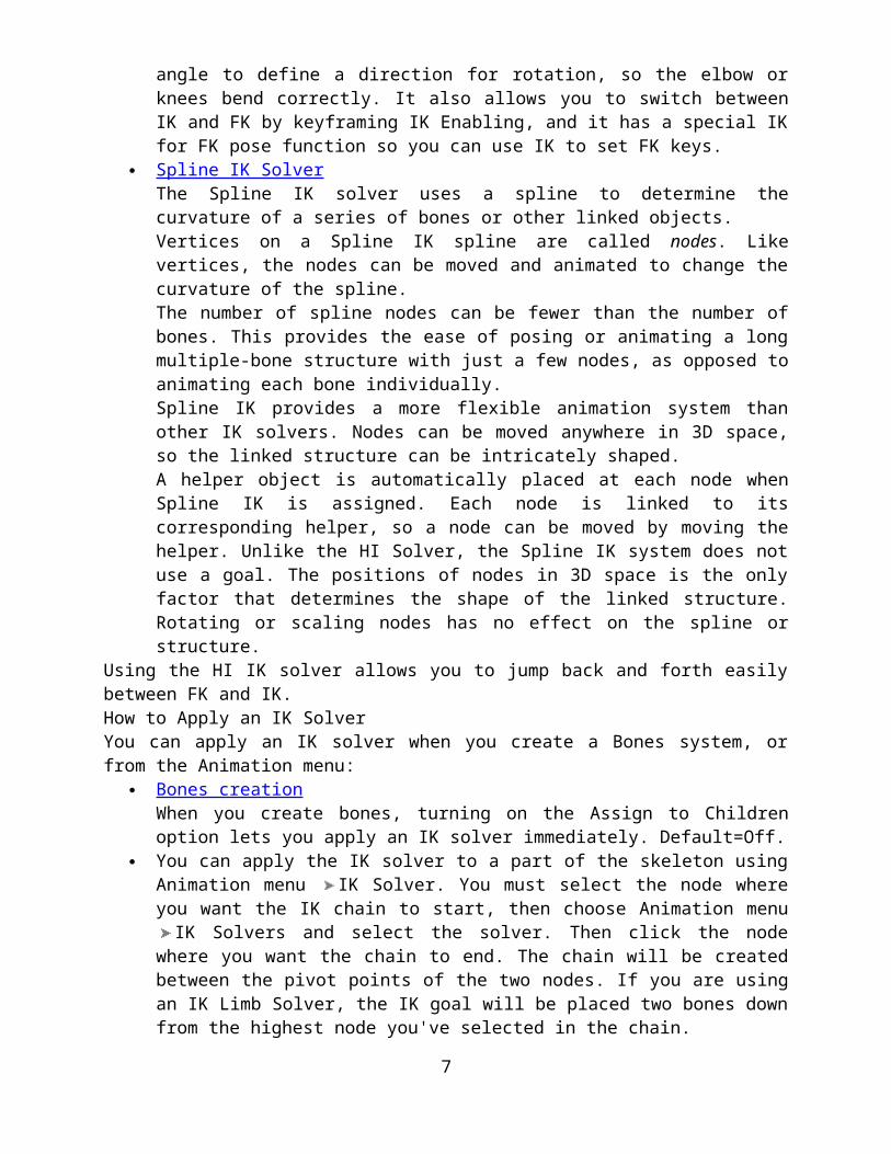
Because this solver's algorithm is history-independent, it is fast to use regardless of how many frames of animation are involved. Its speed is the same on frame 2000 as it is on frame 10. It is stable and jitter-free in viewports. This solver creates a goal and an end effector (although the display of end effector is off by default). It uses a swivel angle to adjust the solver plane to position the elbow or the knee. You can target the swivel angle to an another object to animate it. IK Limb Solver also uses a preferred angle to define a direction for rotation, so the elbow or knees bend correctly. It also allows you to switch between IK and FK by keyframing IK Enabling, and it has a special IK for FK pose function so you can use IK to set FK keys.
Spline IK Solver The Spline IK solver uses a spline to determine the curvature of a series of bones or other linked objects. Vertices on a Spline IK spline are called nodes. Like vertices, the nodes can be moved and animated to change the curvature of the spline. The number of spline nodes can be fewer than the number of bones. This provides the ease of posing or animating a long multiple-bone structure with just a few nodes, as opposed to animating each bone individually. Spline IK provides a more flexible animation system than other IK solvers. Nodes can be moved anywhere in 3D space, so the linked structure can be intricately shaped. A helper object is automatically placed at each node when Spline IK is assigned. Each node is linked to its corresponding helper, so a node can be moved by moving the helper. Unlike the HI Solver, the Spline IK system does not use a goal. The positions of nodes in 3D space is the only factor that determines the shape of the linked structure. Rotating or scaling nodes has no effect on the spline or structure.
Using the HI IK solver allows you to jump back and forth easily between FK and IK. How to Apply an IK Solver You can apply an IK solver when you create a Bones system, or from the Animation menu:
Bones creation When you create bones, turning on the Assign to Children option lets you apply an IK solver immediately. Default=Off.
You can apply the IK solver to a part of the skeleton using Animation menu IK Solver. You must select the node where you want the IK chain to start, then choose Animation menu IK Solvers and select the solver. Then click the node where you want the chain to end. The chain will be created between the pivot points of the two nodes. If you are using an IK Limb Solver, the IK goal will be placed two bones down from the highest node you've selected in the chain.
Where to Adjust the IK Solver You adjust IK solver settings in the Motion and Hierarchy panels:
Motion panel When the goal of an IK chain is selected, the motion panel displays the rollouts for the individual IK solver. HI SolverMotion panel parameters adjust the swivel angle of the solver plane, to point the knees and elbows. Also, the controls in the IK Solver rollout let you mix periods of IK with FK (forward kinematics) through the Enabled button and the IK button. HD SolverMotion panel parameters assign, remove, and edit the end effector for the currently selected joint. You can parent the end effector to another object, and return the skeleton to
5

an initial pose. Changing IK controller parameters in the Motion panel affects the entire HD IK chain, even when you've selected only a single bone. IK Limb SolverMotion panel parameters for the IK Limb solver are the same as for the HI Solver. Spline IK SolverMotion panel parameters allow you to activate/deactivate the solver, adjust the bones assigned to the start and end joints, adjust start and end twist angles and make twist handle display settings.
Hierarchy panel HI SolverWhen a bone is selected, the IK panel displays controls to activate and limit the rotational joints, and set a preferred angle for the joints. The preferred-angle poses of all the joints help control the direction of rotation of the limbs. When a goal is selected, the IK panel is blank. HD SolverSelect the end effector of an HD IK chain. In the Hierarchy panel, click IK. The controls that appear affect the HD Solver. You will also find the tools to bind to follow objects, and set precedence and joint limits, damping and spring back. IK Limb SolverWhen a bone is selected, the IK panel displays controls to activate and limit the rotational joints, and set a preferred angle for the joints. The preferred-angle poses of all the joints help control the direction of rotation of the limbs. When a goal is selected, the IK panel is blank. If you select a bone before applying an IK Solver, a different set of sliding and rotational joint parameters will be displayed, but these will be replaced once an IK Solver is applied. Spline IK SolverSelect the spline of an Spline IK chain. In the Hierarchy panel, click IK. The controls that appear affect the Spline IK Solver. You will also find the tools to bind to follow objects, and set precedence and joint limits, damping and spring back. The controls in the IK panel are similar to the HD Solver.
Procedures To add an IK solver to a hierarchy or bones system:
1. Create a bones system or any other linked hierarchy of objects.
2. Select a bone or an object where you'd like the IK chain to start. 3. Choose Animation menu IK Solver, and then choose the IK solver:
o HI Solver for character animationo HD Solver for mechanical assemblages with sliding jointso IK Limb Solver for two-bone chainso Spline IK Solver for improved control of intricate, multiple-bone structures
4. Click where you want the IK chain to end. If you are using the IK Limb Solver, you must apply the IK Solver to control only two bones. The IK solver appears in the viewport.
To create a bones hierarchy that uses an IK solver:
1. Go to the Create panel, click (Systems), and click Bones. 2. On the IK Chain Assignment rollout, choose an IK solver from the list.3. Turn on Assign To Children.4. Click and drag in a viewport to create the bones. Right-click to stop bone creation.
6
The bones are created with the IK solver already applied. NoteIf you use the Spline IK solver, a Spline IK Solver dialog opens where you can make special settings for the spline and helpers used by the solver.
To display a hierarchy of objects as bones:
1. Select the hierarchy of objects in the viewport. 2. From the Animation menu, choose Bone Tools.
This Opens the Bone Tools dialog. 3. Expand the Object Properties rollout.4. In the Bone Properties group, turn on Bone On.5. On the Display panel, scroll down to Link Display and expand it.6. On the Link Display rollout, turn on Display Links, and Link Replaces Object.
The objects disappear and the links are displayed as bones. History-Independent (HI) IK SolverThe HI (History-Independent) Solver does not rely on IK solutions calculated in previous keyframes in the timeline, so it is just as fast to use at frame 2000 as it is at frame 20. The HI Solver uses a goal to animate a chain. You animate the goal and the IK solver attempts to move the end effector (the pivot point of the last joint of the chain) to match the position of the goal. Often the goal is parented to other control objects such as points or dummies, splines or bones, and these control objects in turn are wired to viewport or rollout sliders. The IK solution takes place in a plane, known as the solver plane. The angle of the solver plane in world space is controlled by a parameter called the swivel angle. The swivel angle is animatable. You can adjust it directly, or with a manipulator. The HI Solver allows for the creation of multiple or overlapping chains. This allows you to create multiple goals for additional controls. By linking the goals to points, splines, bones or dummies, you can create simple controls to animate complex chains or hierarchies. You can also use constraints on these goals or control objects, as another animation tool. Applying an HI Solver To apply an HI Solver to any part of a hierarchy select the bone or object where you want to the solver to start. Then choose Animation menu IK Solvers HI Solver. In the active viewport move your cursor to the bone where you want the chain to end. When you click to select that bone, the goal is drawn at the pivot point of that bone. If you want a goal at the far end of the bone, refine the bone where you want to goal to be placed. An extra bone will be added, and then choosing that bone allows you place the goal at the end. When you create bones, a small "nub" bone is automatically created at the end of the chain to assist in this process. Setting Up Multiple Chains To rig a skeleton for a human leg you could use three chains in one leg, as follows:
The first chain is created from the hip to the ankle. This chain controls the overall leg motion including bending of the knee.
The second chain is created from the ankle to the ball of the foot. This chain controls the heel's up and down motion.
The third chain is created from the ball of the foot to the toe. When the three chains work together they help to maintain the foot’s position in space. This means it will keep the foot planted on the ground as the character’s body moves. All three IK chains in this hip-to-toe setup place goals at key positions in the foot that mimic natural foot behavior. In real life, the toe, ball of the foot, and heel can be planted on the ground or raised.
7
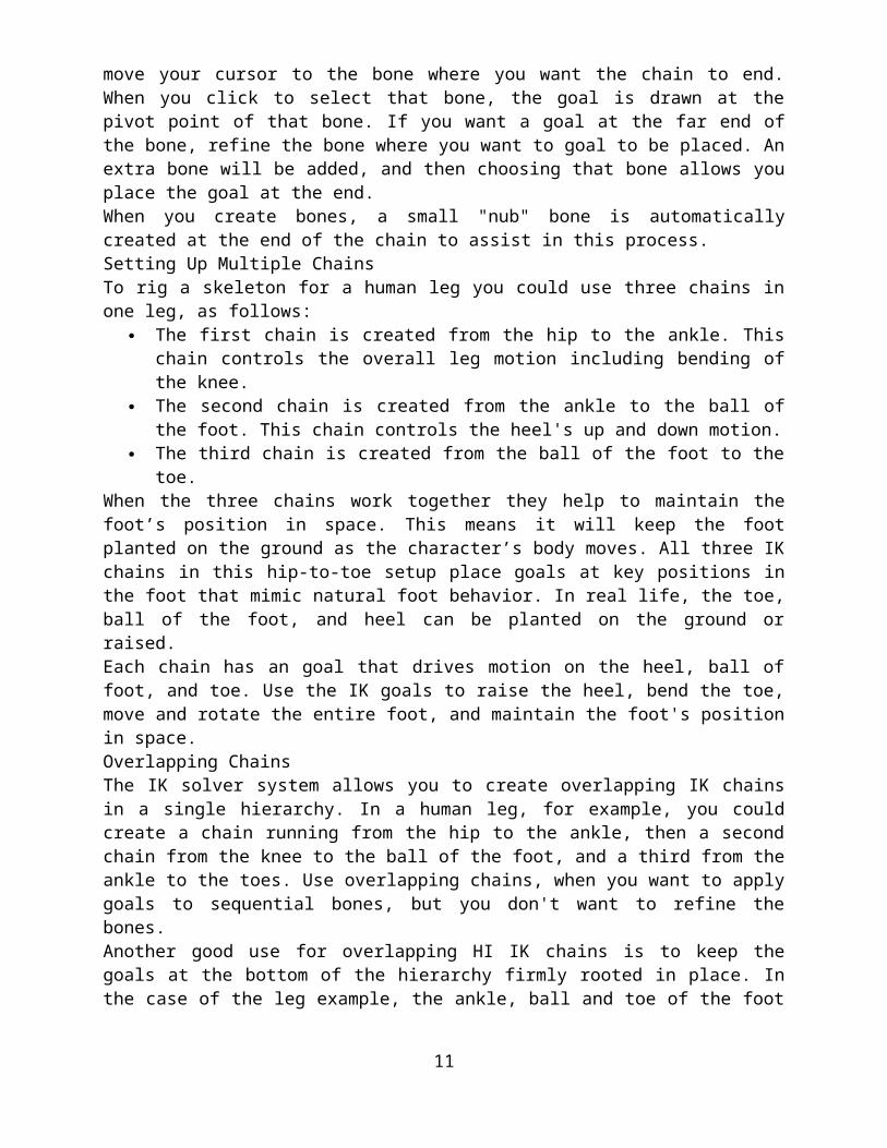
Each chain has an goal that drives motion on the heel, ball of foot, and toe. Use the IK goals to raise the heel, bend the toe, move and rotate the entire foot, and maintain the foot's position in space. Overlapping Chains The IK solver system allows you to create overlapping IK chains in a single hierarchy. In a human leg, for example, you could create a chain running from the hip to the ankle, then a second chain from the knee to the ball of the foot, and a third from the ankle to the toes. Use overlapping chains, when you want to apply goals to sequential bones, but you don't want to refine the bones. Another good use for overlapping HI IK chains is to keep the goals at the bottom of the hierarchy firmly rooted in place. In the case of the leg example, the ankle, ball and toe of the foot would not move until the upper portion of the hierarchy had reached its full stretch.
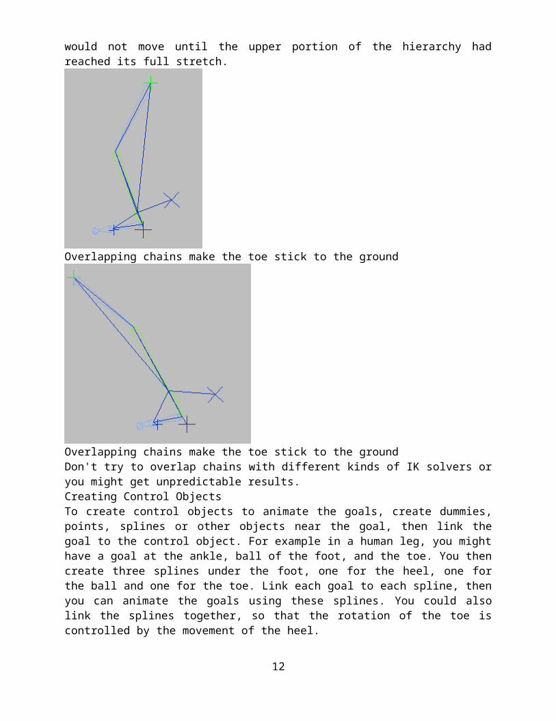
Overlapping chains make the toe stick to the ground
Overlapping chains make the toe stick to the groundDon't try to overlap chains with different kinds of IK solvers or you might get unpredictable results. Creating Control Objects To create control objects to animate the goals, create dummies, points, splines or other objects near the goal, then link the goal to the control object. For example in a human leg, you might have a goal at the ankle, ball of the foot, and the toe. You then create three splines under the foot, one for the heel, one for the ball and one for the toe. Link each goal to each spline, then you can
8

animate the goals using these splines. You could also link the splines together, so that the rotation of the toe is controlled by the movement of the heel. Besides hierarchical linkage, you can now use the new Constraint system in conjunction with IK solvers. You could apply any of the constraints to create a relationship between the goals or bones and other objects. The goal could be position constrained to a dummy which is moved. Or you could create three bone chains that are all in the same place, and constrain one bone chain to another, then weight the constraints.
Bone chains constrained together Using control objects gives you something bigger to select in the viewport. You can also use control objects to separate chains, for example in a human arm one chain could end at the wrist and another separate chain be created for the hand and fingers. The control object at the wrist serves as the root node for the hand chain, yet that chain would remain disconnected (hierarchically speaking) from the arm chain. You can create viewport sliders using the manipulator helper, and then use the viewport sliders to control the transforms of the control objects. Use wire parameters to hook up the sliders with the control objects. You can also create Custom Attributes to add these sliders to the object rollouts. Mixing Forward Kinematics with Inverse Kinematics The HI IK solver provides a tool for mixing FK and IK in a single animation track. There is an FK subcontroller beneath the IK controller assigned by this solver. When the Enabled button is on, the FK subcontroller values are preserved but ignored. When Enabled is turned off, the FK subcontroller values apply. To access the Enabled button, select the goal and go to the Motion panel, then turn off the Enabled button. This will allow you to animate using FK rotations of the bones or hierarchy objects. IK for FK pose allows one to turn on IK in middle of FK manipulation. When the Enabled button is turned off, and IK for FK Pose is on, then selecting and moving the goal lets you use IK to create the forward kinematic keyframes. Moving the goal poses the skeleton and add rotation keys to all the objects in the chain when the Auto Key button is on. When working with IK and FK together it is possible to create a situation where the goal has moved away from the end of the chain. Use the IK/FK snap button to reposition the goal, snapping it back to the end of the chain. When AutoSnap is on, the snap happens automatically; when you touch the goal, you don't have to click the IK/FK snap button. Controlling HI IK Precision When you are animating with HI Solvers, if you find the animation of the limbs is not smooth, you should try doubling the Iterations in the Solutions group of the HI Solver Properties rollout. You can also try reduce the Thresholds value to smooth the animation. History-Dependent (HD) IK Solver
9

Select a node of hierarchy or bone chain. Animation menu IK Solvers HD Solver Click a second node of chain. Animating with the HD Solver lets you use sliding joints combined with inverse kinematics. It has controls for spring back, damping, and precedence not found in the HI Solver. It also has quick tools for viewing the initial state of the IK chain. Use it for animations of machines and other assemblies. Since this is history dependent, performance is slower at the end of long animations. For lengthy scenes, use HI Solvers, if possible. Animating the End Effectors You animate a hierarchy of objects or bone structure using HD Solvers by animating special end effectors located at the bone joints. There are two types of end effectors: Position and Rotation. They are displayed as three intersecting blue lines at the joint. When you select and transform a joint that carries either end effector, only the end effector itself is transformed. The objects or bones in the chain then use IK to calculate the IK solution. Animating these end effectors is much like animating with Interactive IK except interpolation between keyframes uses correct IK solutions. Linking End Effectors to a Parent You can link HD IK end effectors to a parent to achieve results similar to using bound follow objects with Interactive and Applied IK. To link a HD IK end effector, you click Link on the Motion panel. There are two reasons to link an end effector to a parent:
You can rescale your entire hierarchy. If you animate a robot, and then later decide you want to scale the entire robot and its animation, link the robot's root object to a dummy, link all of the robot's end effectors to the same dummy, and then scale the dummy to scale all of the hierarchical objects as well as the animation of the end effectors.
You can use linked end effectors for things like feet or hands. End-effectors are automatically bound to the world, so when you move a root object in your hierarchy, the end effectors remain behind. This is good for keeping feet on the ground, but not very good for hands, where you want them to move along with the character. To have hands follow the root object, link the end effectors of the hands to the root object.
Linking Bones to Follow Objects You can also use follow objects instead of end effectors and bind bones to any number of follow objects using Interactive IK. If you use follow objects with HD IK, you do not need to click Apply IK. The IK solver takes care of everything automatically. IK Limb SolverThe IK Limb solver is specifically meant for animating the limbs of human characters; for example, the hip to the ankle, or the shoulder to the wrist. Each IK Limb solver affects only two bones in a chain, but multiple solvers can be applied to different parts of the same chain. It is an analytical solver that is very fast and accurate in viewports. To use the IK Limb solver, a bones system must have at least three bones in the chain. The goal is placed at the pivot point of the bone that is two bones away from the first selected bone. The IK Limb solver works not only with bone hierarchies, but with any linked hierarchy that has at least three elements, and is set up to model a human limb. The additional requirements are:
The first joint is "spherical." That is, it has three degrees of freedom. The second joint is "revolute," a robotics term that means it is based on a pin and has one
degree of freedom.The IK Limb solver uses the same controls as the HI Solver, so it allows for mixing periods of forward and inverse kinematics in the same animation period. It does not use the HD Solver
10
methods of damping, precedence, and setting joint limits, instead it has a preferred angle parameter, swivel plane and IK/FK Enabling. The IK Limb solver can be exported directly to a game engine. Procedures To apply a IK limb solver:
1. Create a chain that has three bones.
2. Select the root of the chain. 3. From the Animation menu, choose IK Solvers IK Limb Solver. 4. In the viewport, move the mouse. You will see a dotted line attached to the cursor as you
move the mouse.5. Click the third bone in the chain, or any bone after the third bone.
The IK Limb solver displays on the bone chain. The IK Limb solver only affects two bones in the chain, but you need to select the third bone to put it on the other two bones.
To animate an IK limb solver chain: 1. Apply the IK Limb solver to a two bone chain, with joint limits as described above.
2. Select the goal.
3. Move or rotate the goal. Interface The Interface for the IK Limb solver is identical to that of the HI Solver.
Select the goal at the end of the chain, and open the Motion panel. Here you will see the controls for the IK Limb solver. (The fourth is available from the Hierarchy IK panel when a bone is selected.) Spline IKAnimation menu IK Solvers Spline IK Solver
Create panel (Systems) Bones Choose SplineIKSolver from the IK Solver list. The Spline IK solver uses a spline to determine the curvature of a series of bones or other linked objects.
11
You can move and animate the spline vertices to change the curvature of the spline. Usually, a helper is placed at each vertex to assist in animating the spline. The spline curvature is then passed on to the entire linked structure. The bones themselves do not change shape. Normally the number of spline vertices and bones are the same, but you can use fewer vertices for easier posing and animating a long multiple-bone structure with just a few nodes, as opposed to animating each bone individually. Spline IK provides a more flexible animation system than other IK solvers. You can position vertices/helpers anywhere in 3D space, so the linked structure can assume any shape you want to give it. A helper object is automatically placed at each vertex when Spline IK is assigned. Each vertex is linked to its corresponding helper, so a vertex can be moved by moving the helper. Unlike the HI Solver, the Spline IK system does not use a goal. The positions of helpers/vertices in 3D space is the only factor that determines the shape of the linked structure. NoteMoving the Spline IK helpers to curl the spline can sometimes cause bones to rotate or flip unexpectedly. If this happens, you can try choosing a different upnode object with the IK chain's Pick Upnode option in the IK Solver Properties rollout (see Spline IK Solver Rollouts), or use a different IK method for your hierarchy. Applying a Spline IK Solver The Spline IK solver can be applied at the time bones are created, or after the bone structure has already been made. To apply a spline IK solver when bones are created:
1. Go to the Create panel, click (Systems), then click Bones. 2. On the IK Chain Assignment rollout, set IK Solver to SplineIKSolver, and turn on both
checkboxes: Assign To Children and Assign To Root. By default, Assign To Root is on automatically when you turn on Assign To Children.
3. Draw the bone structure as usual. When you right-click to end the bone creation process, the Spline IK Solver dialog appears. Set parameters and click OK.
12

This procedure automatically draws the spline based on your dialog selections and sets up the Spline IK system to work with the spline. 3ds Max automatically assigns a Path constraint to the root bone to constrain it to the helper/vertex at that end of the spline.
To apply a Spline IK solver to an existing bone structure: 1. Create a bone structure without an IK chain.2. Draw a spline or NURBS curve to be used by the bones. The curve can have any length
and shape, and does not have to match the length or shape of the bone structure.
3. Select the bone or object where you want to the solver to start. 4. Choose Animation menu IK Solvers Spline IK Solver. In the viewport, move the
cursor to the bone or object where you want the chain to end and click that bone. Then move the cursor to the spline and click it.
13
The bone structure jumps to the spline and takes its shape, and a helper is created on the spline at each vertex. A Path constraint is automatically assigned to the root bone to constrain it to the helper/vertex at that end of the spline.
To specify a spline after the spline IK solver is applied: You can also apply a Spline IK solver to an existing bone structure without selecting a spline, then choose the spline later.
1. Create a bone structure without an IK chain.
2. Select the bone or object where you want to the solver to start. 3. Choose Animation menu IK Solvers Spline IK Solver. In the viewport, move the
cursor to the bone or object where you want the chain to end and click that bone. Then right-click in the viewport to end the IK solver creation without choosing a spline.
14
4. Create a spline or NURBS curve to be used with the Spline IK system. It is recommended that you apply the Spline IK Control modifier to it and then click Create Helpers to place helpers at each vertex, making the spline easier to control.
5. Select the IK chain cross hairs and go to the Motion panel. On the Spline IK Solver rollout, click Pick Shape and click the spline. With this method, the position constraint is not automatically assigned to the root bone, so it must be assigned manually.
6. Select the root bone. Choose Animation menu Constraints Path Constraint, and then click the spline. This moves the bone structure to the spline, if they're apart, and creates a Position List controller for the bone with the Path Constraint as the second (active) constraint. NoteThis also animates the bones along the path. If you don't want this, delete the second animation key.
Working with the Spline IK Solver To use the Spline IK Solver, move the helpers to shape the spline. Do not move the spline. The shape of the spline is determined by the positions of the vertices, so moving the spline itself has no effect on the bone structure. If the spline is moved, it will snap back to the helpers the next time a helper is moved. However, it is recommended that you not move the spline at all. Once you have finished setting up the spline IK solver, it can be helpful to freeze the spline to avoid accidentally moving it. Moving helpers changes the shape of the spline. To twist the spline, select the spline IK chain object and go to the Motion panel to change twist angles in the IK Solver Properties rollout.
15