Integrated Effects of Disruptions and Integrated Effects of Disruptions and ELMsELMs on Divertor and Nearby Componentson Divertor and Nearby Components
Valeryi SizyukAhmed Hassanein
School of Nuclear Engineering Center for Materials Under eXtreme Environment
Purdue University
PFC community meeting at UCLAAugust 4-6, 2010, Los Angeles CA
2
Outline
HEIGHTS Integrated Package
Divertor Nearby Fluxes and Assumptions
Application to ITER Divertor Area
Simulation Results
HEIGHTS Upgrade and Current Status
Summary
3
Recent Publications ELMs and Disruptions
1. V. Sizyuk and A. Hassanein, Damage to nearby divertor components of ITER- like devices during giant ELMs and disruptions, Nucl. Fusion (2010), Just submitted
2. A. Hassanein, T. Sizyuk, V. Sizyuk, G. Miloshevsky, Impact of various plasma instabilities on reliability and performance of tokamak fusion devices, Fusion Eng. Des., In Press, (2010)
3. S. El-Morshedy, A. Hassanein, Analysis, verification, and benchmarking of the transient thermal hydraulic ITERTHA code for the design of ITER divertor, Fusion Eng. Des., In Press, (2010)
4. A. Hassanein, T. Sizyuk, I. Konkashbaev, Integrated simulation of plasma surface interaction during edge localized modes and disruptions: Self-consistent approach, J. Nucl. Mater., 390-391 777 (2009)
HEIGHTS Integrated Package
4
Recent Publications (Cont.) Vertical Displacement Events
1. A. Hassanein and T. Sizyuk, Comprehensive simulation of vertical plasma instability events and their serious damage to ITER plasma facing components, Nucl. Fusion, 48 115008 (2008)
2. A. Hassanein, T. Sizyuk, M. Ulrickson, Vertical displacement events: A serious concern in future ITER operation, Fusion Eng. Des., 83 1020 (2008)
3. S. El-Morshedy, A. Hassanein, Transient thermal hydraulic modeling and analysis of ITER divertor plate system, Fusion Eng. Des., 84 2158 (2009)
Runaway Electrons1. V. Sizyuk and A. Hassanein, Self-consistent analysis of the effect of runaway
electrons on plasma facing components in ITER, Nucl. Fusion, 49 095003 (2009)
HEIGHTS Integrated Package
5
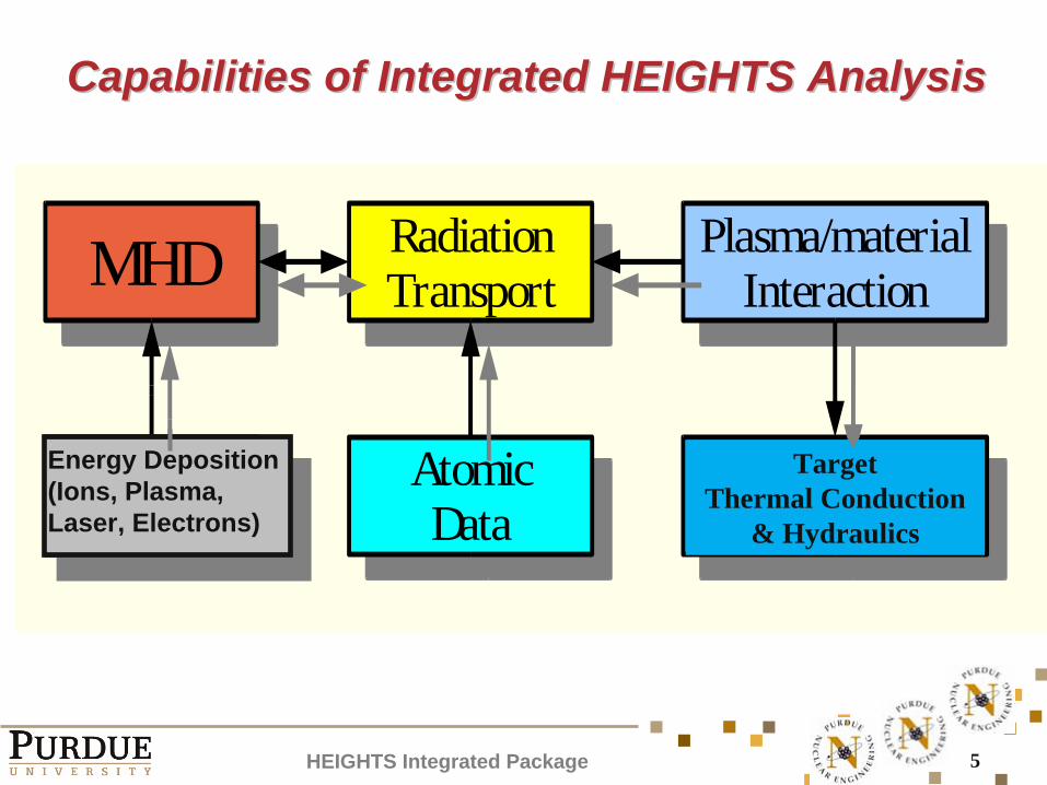
Capabilities of Integrated HEIGHTS AnalysisCapabilities of Integrated HEIGHTS Analysis
HEIGHTS Integrated Package
MHD RadiationTransport
Plasma/materialInteraction
ExternalCircuit
AtomicData
Electrode Thermal Conduction
& Hydraulics
Energy Deposition(Ions, Plasma, Laser, Electrons)
TargetThermal Conduction
& Hydraulics
6
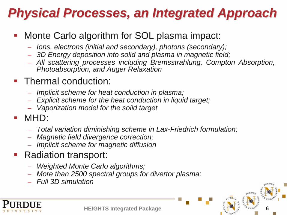
Physical Processes, an Integrated ApproachPhysical Processes, an Integrated Approach
Monte Carlo algorithm for SOL plasma impact:– Ions, electrons (initial and secondary), photons (secondary);– 3D Energy deposition into solid and plasma in magnetic field;– All scattering processes including Bremsstrahlung, Compton Absorption,
Photoabsorption, and Auger Relaxation
Thermal conduction:– Implicit scheme for heat conduction in plasma;– Explicit scheme for the heat conduction in liquid target;– Vaporization model for the solid target
MHD:– Total variation diminishing scheme in Lax-Friedrich formulation;– Magnetic field divergence correction;– Implicit scheme for magnetic diffusion
Radiation transport:– Weighted Monte Carlo algorithms;– More than 2500 spectral groups for divertor plasma;– Full 3D simulation
HEIGHTS Integrated Package
7
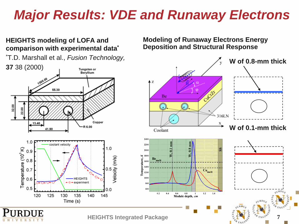
HEIGHTS modeling of LOFA and comparison with experimental data*
*T.D. Marshall et al., Fusion Technology, 37 38 (2000)
W of 0.8-mm thick
W of 0.1-mm thick
Modeling of Runaway Electrons Energy Deposition and Structural Response
Major Results: VDE and Runaway Electrons
HEIGHTS Integrated Package
8
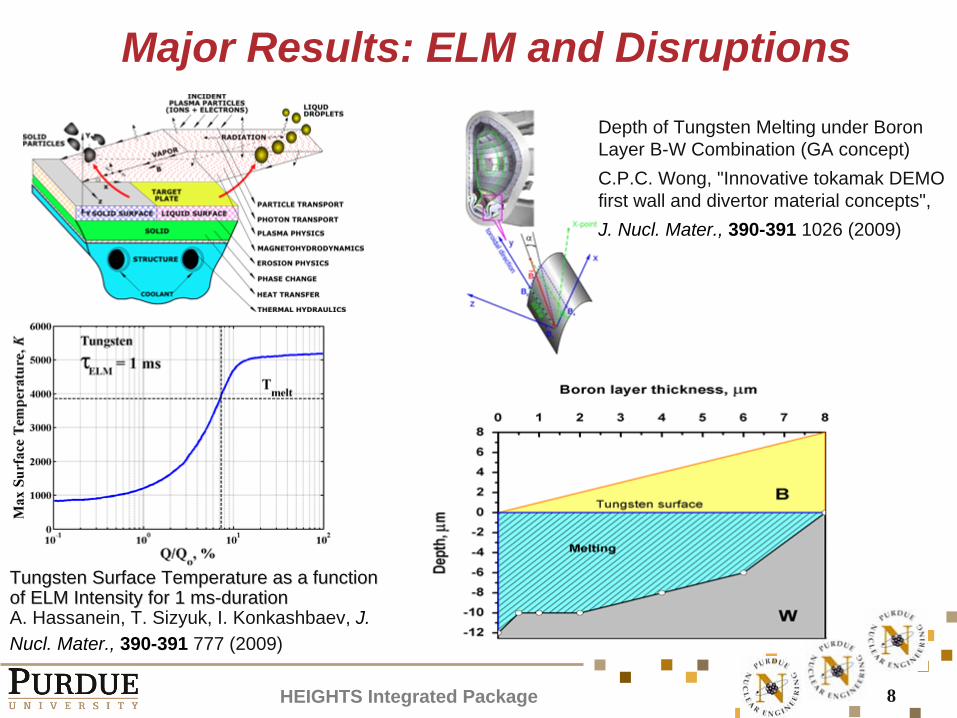
Major Results: ELM and Disruptions
Tungsten Surface Temperature as a function Tungsten Surface Temperature as a function of ELM Intensity for 1 msof ELM Intensity for 1 ms--durationduration A. Hassanein, T. Sizyuk, I. Konkashbaev, J. Nucl. Mater., 390-391 777 (2009)
Depth of Tungsten Melting under Boron Layer B-W Combination (GA concept)C.P.C. Wong, "Innovative tokamak DEMO first wall and divertor material concepts", J. Nucl. Mater., 390-391 1026 (2009)
HEIGHTS Integrated Package
9
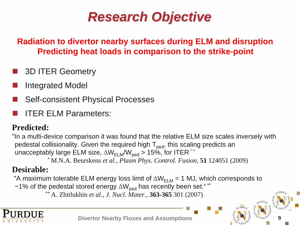
Research ObjectiveResearch Objective
Divertor Nearby Fluxes and Assumptions
Radiation to divertor nearby surfaces during ELM and disruption Predicting heat loads in comparison to the strike-point
3D ITER Geometry
Integrated Model
Self-consistent Physical Processes
ITER ELM Parameters:
Predicted:"In a multi-device comparison it was found that the relative ELM size scales inversely with pedestal collisionality. Given the required high Tped , this scaling predicts an unacceptably large ELM size, ∆WELM /Wped > 15%, for ITER.“ *
* M.N.A. Beurskens et al., Plasm Phys. Control. Fusion, 51 124051 (2009)Desirable:"A maximum tolerable ELM energy loss limit of ∆WELM = 1 MJ, which corresponds to ∼1% of the pedestal stored energy ∆Wped has recently been set.“ **
** A. Zhitlukhin et al., J. Nucl. Mater., 363-365 301 (2007)
10
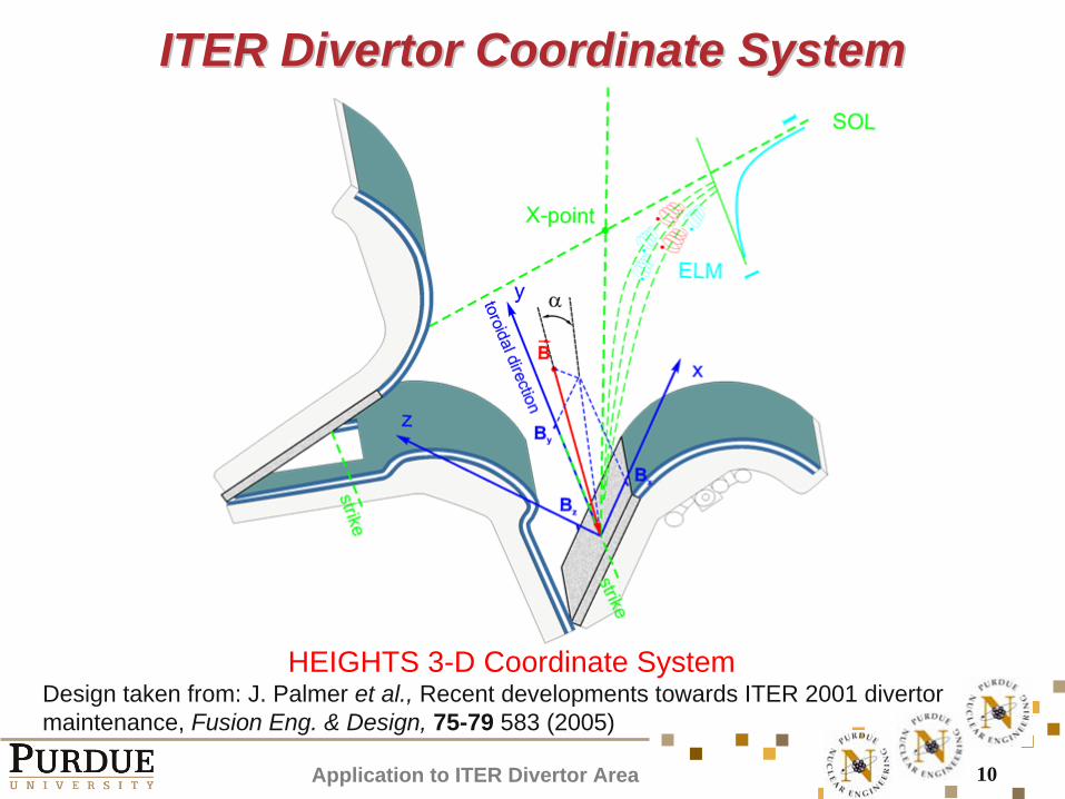
ITER DivertorITER Divertor Coordinate Coordinate SystemSystem
HEIGHTS 3-D Coordinate SystemDesign taken from: J. Palmer et al., Recent developments towards ITER 2001 divertor maintenance, Fusion Eng. & Design, 75-79 583 (2005)
Application to ITER Divertor Area
11
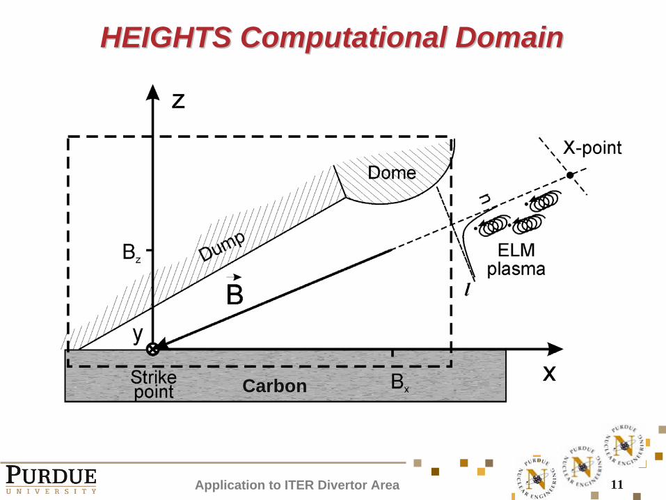
HEIGHTS Computational DomainHEIGHTS Computational Domain
Carbon
Application to ITER Divertor Area
12
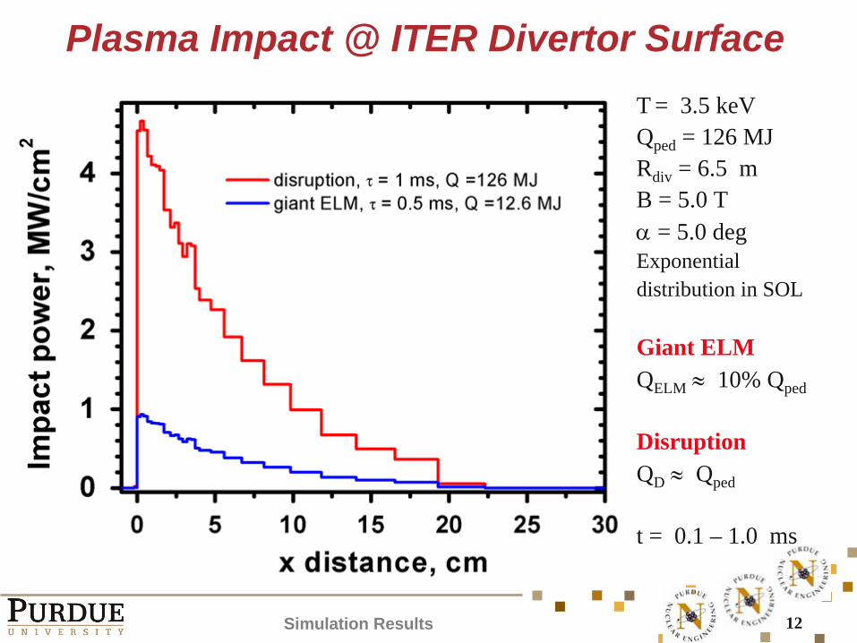
Plasma Impact @ ITER Divertor SurfaceT = 3.5 keVQped = 126 MJRdiv = 6.5 mB = 5.0 T
= 5.0 deg
Exponential distribution in SOL
Giant ELMQELM
10% Qped
DisruptionQD
Qped
t = 0.1 – 1.0 ms
Simulation Results
13
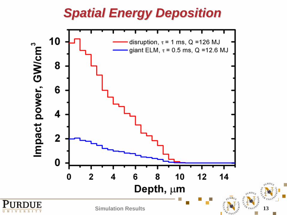
Spatial Energy DepositionSpatial Energy Deposition
Simulation Results
14
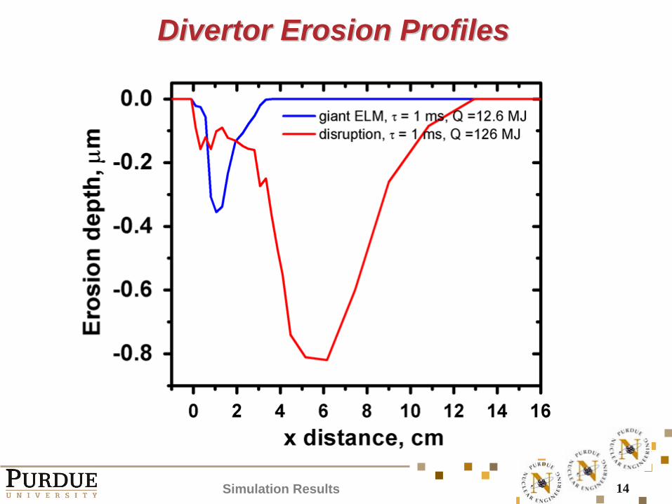
Divertor Erosion ProfilesDivertor Erosion Profiles
Simulation Results
15
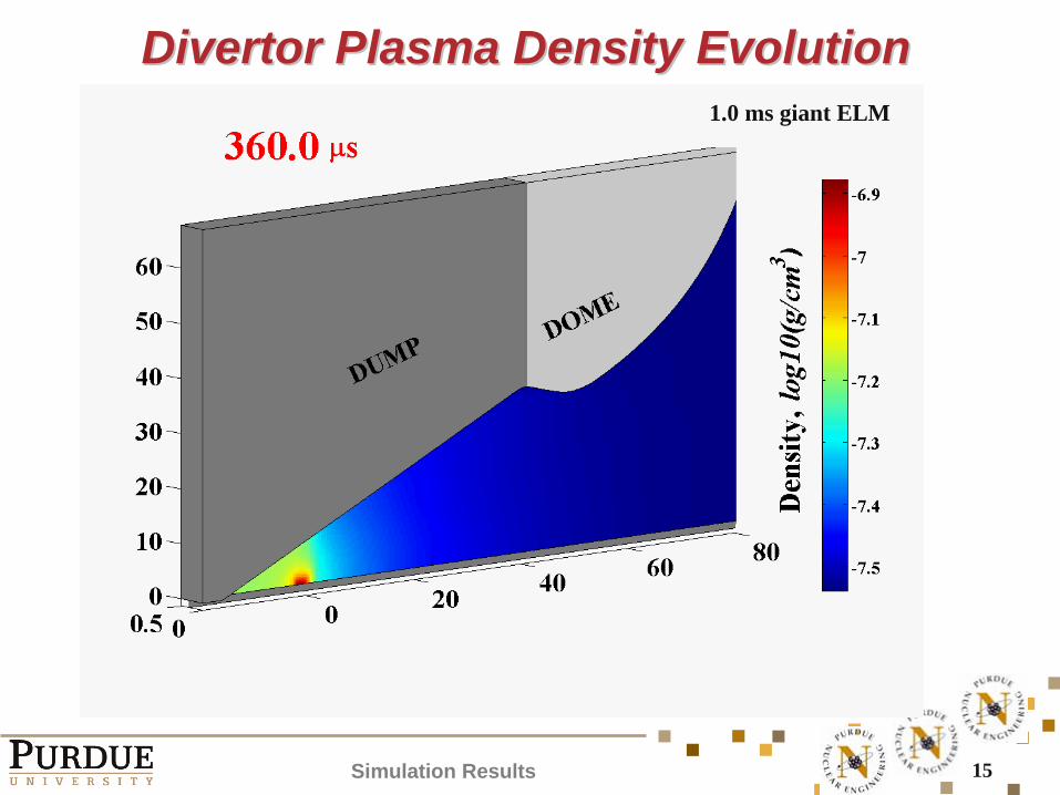
Divertor Plasma Density EvolutionDivertor Plasma Density Evolution1.0 ms giant ELM
Simulation Results
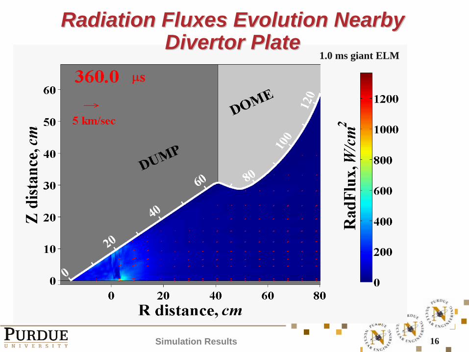
16
Radiation Fluxes Radiation Fluxes Evolution Nearby Evolution Nearby Divertor PlateDivertor Plate
1.0 ms giant ELM
Simulation Results
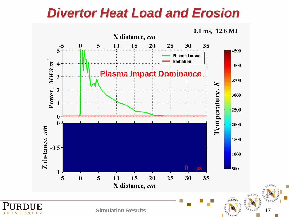
17
Divertor Heat Load and ErosionDivertor Heat Load and Erosion0.1 ms, 12.6 MJ
Simulation Results
Plasma Impact Dominance
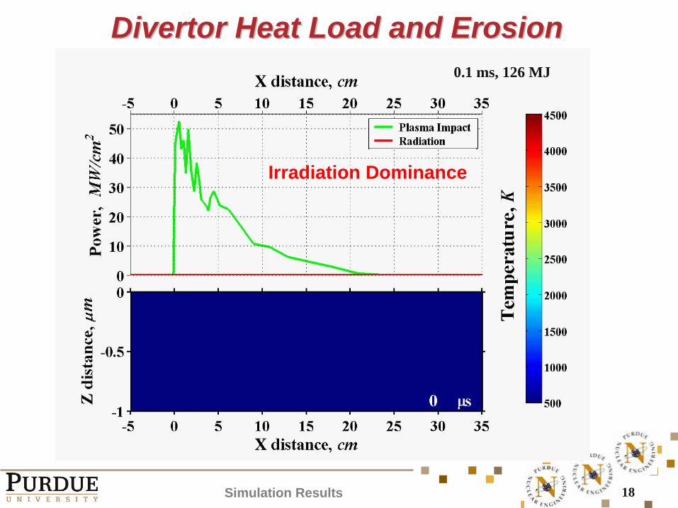
18
Divertor Heat Load and ErosionDivertor Heat Load and Erosion0.1 ms, 126 MJ
Simulation Results
Irradiation Dominance
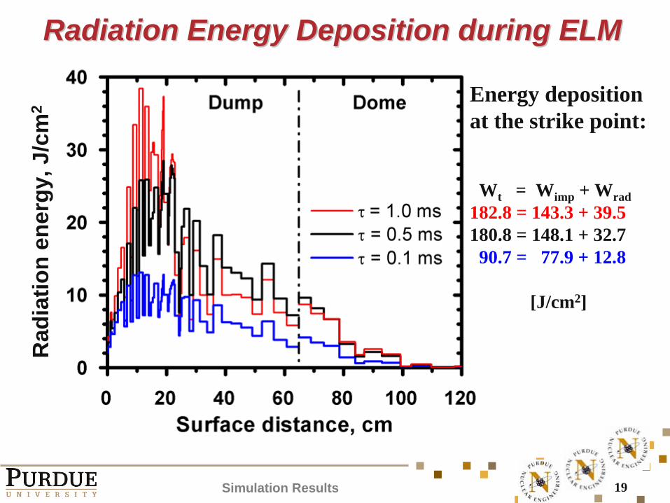
19
Radiation Energy Deposition during ELMRadiation Energy Deposition during ELM
Energy deposition at the strike point:
Wt = Wimp + Wrad182.8 = 143.3 + 39.5180.8 = 148.1 + 32.790.7 = 77.9 + 12.8
[J/cm2]
Simulation Results
Rad
iatio
n en
ergy
, J/c
m2
20
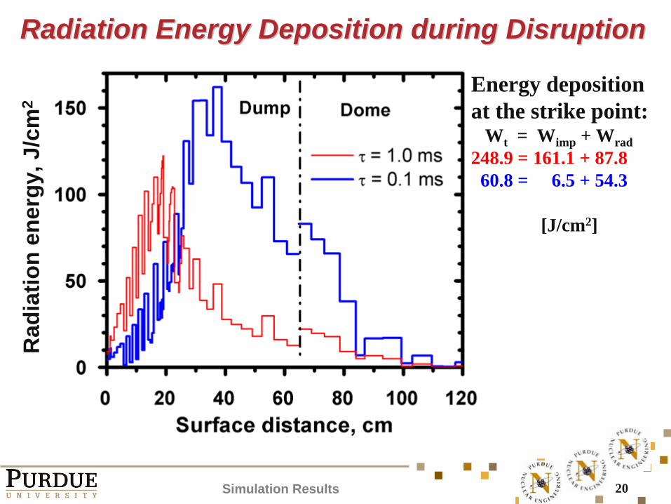
Radiation Energy Deposition during DisruptionRadiation Energy Deposition during Disruption
Energy deposition at the strike point:
Wt = Wimp + Wrad248.9 = 161.1 + 87.860.8 = 6.5 + 54.3
[J/cm2]
Simulation Results
Rad
iatio
n en
ergy
, J/c
m2
21
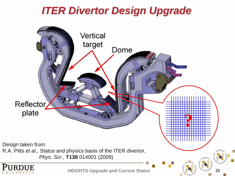
ITER Divertor Design UpgradeITER Divertor Design Upgrade
Design taken from:R.A. Pitts et al., Status and physics basis of the ITER divertor,
Phys. Scr., T138 014001 (2009)
HEIGHTS Upgrade and Current Status
?
22
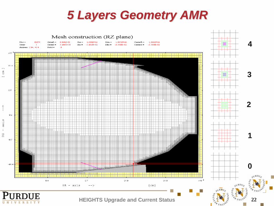
5 Layers Geometry AMR5 Layers Geometry AMR
4
3
2
1
0
HEIGHTS Upgrade and Current Status
23
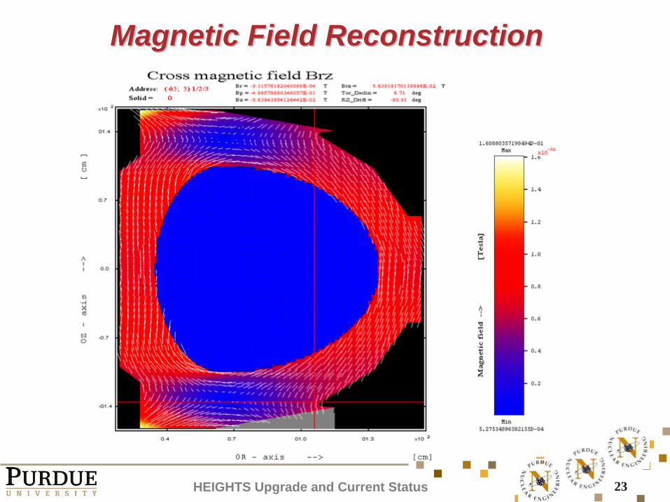
Magnetic Field ReconstructionMagnetic Field Reconstruction
HEIGHTS Upgrade and Current Status
24
Summary and ConclusionSummary and Conclusion
HEIGHTS models and simulation package are upgraded and applied to plasma evolution in divertor nearby areas during ITER giant ELM and disruptions
Heat loads and erosion of carbon vertical target were calculated for ITER-like geometry
Simulation confirmed that nearby divertor surfaces may have radiation fluxes comparable with values incident on the vertical target => Damage to nearby components
The simulation results prove necessity of future model and code enhancement to the new design and its optimization
More detail analysis will be available:V. Sizyuk and A. Hassanein, “Damage to nearby divertor components of ITER- like devices during giant ELMs and disruptions,” Nucl. Fusion (2010), Submitted.
Thank you very much for the attention
Recommended