Embed Size (px)
Citation preview

ZSC31014 Evaluation Kit Description
© 2016 Integrated Device Technology, Inc. 1 April 20, 2016
Restrictions: The IDT ZSC31014 SSC Evaluation Kit hardware and software are designed for ZSC31014 RBiciLite™ evaluation, laboratory setup and module development only. The IDT ZSC31014 SSC Evaluation Kit hardware and software must not be used for module production and production test setups. IDT shall not be liable for any damages arising out of defects resulting from (i) delivered hard and software (ii) non-observance of instructions contained in this manual, or (iii) misuse, abuse, use under abnormal conditions or alteration by anyone other than IDT. To the extent permitted by law, IDT hereby expressly disclaims and User expressly waives any and all warranties, whether express, implied or statutory, including, without limitation, implied warranties of merchantability and of fitness for a particular purpose, statutory warranty of non-infringement and any other warranty that may arise by reason of usage of trade, custom or course of dealing.
Contents 1 Kit Contents .......................................................................................................................... 5 2 ZSC31014 SSC Evaluation Board ........................................................................................ 6
2.1. Overview ......................................................................................................................... 6 2.2. Connections to the ZSC31014 ........................................................................................ 7 2.3. Power Supply to the Board ............................................................................................. 7 2.4. Reset Switch ................................................................................................................... 7 2.5. Connecting a Customer Module to the SCC Evaluation Board ....................................... 7 2.6. Connecting an External Bridge and External Temperature Sensor to the SSC
Evaluation Board ............................................................................................................. 8 3 Installing and Setting up the Software and USB Drivers ....................................................... 8
3.1. Installing the ZSC31014 iLiteTester™ Software ............................................................. 8 3.2. Installing the USB Drivers ............................................................................................... 8 3.3. “Find Com” on the Setup Menu ....................................................................................... 9 3.4. “Change IC Rev” on the Setup Menu .............................................................................. 9 3.5. “I2C Comm Addr” Field ................................................................................................... 9 3.6. Special Feature “Change I2C Speed” on the Setup Menu ............................................. 10 3.7. Special Feature “Find I2C Address” on the Setup Menu ............................................... 10 3.8. Special Feature “Power Down Time” on the Setup Menu ............................................. 10 3.9. Special Feature “Power up all DUTs” on the Setup Menu............................................. 10
4 ZSC31014 iLiteTester™ Software ...................................................................................... 11 4.1. Overview ....................................................................................................................... 11
4.1.1. Log Files .................................................................................................................. 11

ZSC31014 Evaluation Kit Description
© 2016 Integrated Device Technology, Inc. 2 April 20, 2016
4.1.2. Data File caldata.txt ................................................................................................. 11 4.2. Bridge and Temperature Display .................................................................................. 11 4.3. “Log File” Field .............................................................................................................. 13 4.4. “Start CM” Button .......................................................................................................... 13 4.5. “Start NOM” Button ....................................................................................................... 13 4.6. “Normal Mode” Section ................................................................................................. 13
“Run Continuous” Button .................................................................................................... 13 “Sample Rate” Field ............................................................................................................ 13 “Average Samples” Field .................................................................................................... 13
4.7. “EEPROM Editor” Section ............................................................................................. 14 “Read” Button ..................................................................................................................... 14 “Load File” Button ............................................................................................................... 14 “Save File” Button ............................................................................................................... 15
4.8. “Communication and Operation Config” Section ........................................................... 15 “Comm Type” Menu ............................................................................................................ 15 “Clock Freq” Menu .............................................................................................................. 15 “I2C Addr” Field .................................................................................................................. 15 “Lock I2C Address” Checkbox ............................................................................................ 15 “Sleep Mode” Checkbox ..................................................................................................... 15 “Update_Rate” Menu .......................................................................................................... 16 “Sensor Short Check” Checkbox ........................................................................................ 16 “Sensor Connection Check” Checkbox ............................................................................... 16
4.9. Math Config Section ...................................................................................................... 16 “SOT_Curve” Menu ............................................................................................................ 16 “Negative Coeffs” Subsection ............................................................................................. 16
4.10. “Front End Config” Section ............................................................................................ 16 “A2D_Offset” Menu ............................................................................................................. 17 “PreAmp_Gain” Menu ......................................................................................................... 18 “Negative” Checkbox .......................................................................................................... 18 “LongInt” Checkbox ............................................................................................................ 18 “Bsink” Checkbox ................................................................................................................ 18 “Gain8X” Checkbox ............................................................................................................ 18
4.11. “Calibration” Button ....................................................................................................... 18 “Start #”, “Num Asics” and “Get ID” Button ......................................................................... 19
5 Calibration .......................................................................................................................... 19

ZSC31014 Evaluation Kit Description
© 2016 Integrated Device Technology, Inc. 3 April 20, 2016
5.1. Calibration Sequence .................................................................................................... 19 Step 1 – Assigning a Unique Identification (ASIC ID Section) ............................................ 21 Step 2 – Data Collection ..................................................................................................... 21 Step 3 – Calculating and Writing the Coefficients ............................................................... 22
5.2. Dry Run Calibration ....................................................................................................... 23 Steps for a Dry Run Calibration using the Sensor Replacement Board: ............................. 24
6 Calculation of ZSC31014 Calibration Coefficients Off-line.................................................. 26 7 ZSC31014 Software with the IDT SSC Terminal ................................................................ 28
7.1. Protocol ......................................................................................................................... 28 7.2. IDT SSC Terminal ......................................................................................................... 28
8 Command/Data Pair Encoding ........................................................................................... 30 9 Related Documents ............................................................................................................ 31 10 Glossary ............................................................................................................................. 31 11 Document Revision History ................................................................................................ 32 Appendix A: Schematic ZSC31014 SSC Evaluation Board ...................................................... 33 Appendix B: Format of the caldata.txt file ................................................................................. 34

ZSC31014 Evaluation Kit Description
© 2016 Integrated Device Technology, Inc. 4 April 20, 2016
List of Figures Figure 1.1 ZSC31014 SSC Evaluation Kit .............................................................................................................. 5 Figure 2.1 ZSC31014 SSC Evaluation Board Overview ......................................................................................... 6 Figure 2.2 Universal SSC Test Board ..................................................................................................................... 7 Figure 3.1 Setting up Communications ................................................................................................................... 9 Figure 3.2 Select the Specific Power Down Time and “Change I2C Speed” ........................................................ 10 Figure 4.1 Bridge and Temperature Measurements Display ................................................................................ 12 Figure 4.2 EEPROM Editor ................................................................................................................................... 14 Figure 4.3 Select Temperature A2D_Offset .......................................................................................................... 17 Figure 4.4 Calibration Window .............................................................................................................................. 19 Figure 5.1 Initialization Configuration Dialog Box ................................................................................................. 20 Figure 5.2 Initialization Dialog Window with Default Values (Calibration with Artificial Bridge) ........................... 23 Figure 5.3 Initialization Dialog Window with Changed Values (Calibration with SRB) ......................................... 25 Figure 6.1 Fields for Manually Entering Target and Raw Values ......................................................................... 27 Figure 7.1 SSC Terminal Program Sample .......................................................................................................... 29
List of Tables Table 5.1 Offset_B Default Values Determined by A2D_Offset Settings ............................................................ 21 Table 7.1 IDT SSC Terminal Character Assignment ........................................................................................... 28 Table 8.1 Encoding for the 3 Bytes after the Initial I2C WRITE Command Byte ................................................. 30
ZSC31014 Evaluation Kit Description
© 2016 Integrated Device Technology, Inc. 5 April 20, 2016
1 Kit Contents • SSC ZSC31014 Evaluation Board, V1.0
• SSC Communication Board (SSC CB), Ver. X.x, including one USB cable (for further information for the CB, see SSC_Communication Board_VX-x_DataSheet_ Rev_X_x.pdf and SSC_CommunicationBoard_Com-mandSyntax_Rev_X_x.xls in the Manual Evaluation Kit folder on the DVD)
• SSC Sensor Replacement Board (SRB) (SSC Sensor Dummy V2.0)
• SSC DVD, including the ZSC31014 iLiteTester™ software for evaluation and calibration
• 5 ZSC31014DAG1 (SOP8 150mil)
• SSC Kit start up information
Figure 1.1 ZSC31014 SSC Evaluation Kit
The ZSC31014 SSC Evaluation Kit contains the software and hardware needed for communication and calibra-tion of a ZSC31014 sensor signal conditioning IC. A user’s PC can communicate with a ZSC31014 socketed on the SSC Evaluation Board via an SSC Communication Board through a USB connection. The software should function on any Windows® 2000/XP/ Vista / Windows® 7 system after installation of a USB driver. Both the SSC Evaluation Board and the Sensor Replacement Board (SRB) can provide a replacement for a sensor. Only one of these can be used at a time for calibration as determined by the settings of jumpers K6 and K7 (see Figure 2.1). On the SRB, the sensor replacement is controlled by a potentiometer (see Figure 1.1). The SRB can be disconnected if the SSC Evaluation Board’s sensor replacement (artificial bridge stimulus) will be used.
SRB SSC CB
SSC ZSC31014 Evaluation Board
USB Connector
Potentiometer for Artificial Bridge Stimulus
ZSC31014 Evaluation Kit Description
© 2016 Integrated Device Technology, Inc. 6 April 20, 2016
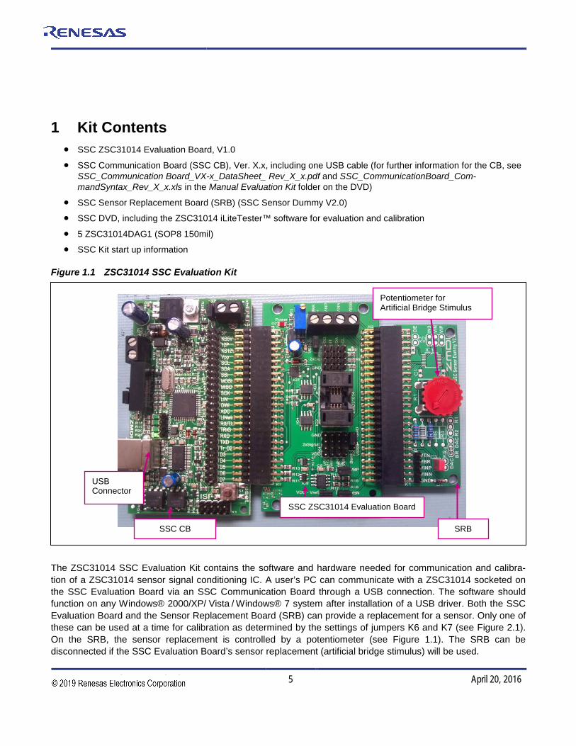
K3 Jumper
Bridge GND to BSink
Bridge GND to VSS
KL1 Connector to External Bridge
Resistors for Board Identification
Pin 1 of ZSC31014
K1 Connector to the SSC CB
Jumper K8 (Default = Shorted) Shorted: Vref = VDD
K2 Connector > Sensor Replacement Board (not applicable if using SSC Board artificial bridge)
Jumpers K6 and K7 Open: SRB Sensor Replacement Shorted: SSC Eval. Board Artificial Bridge
GND GND GND GND
VSS Bsink VBP VBN
VSS Bsink VBP VBN
VDD VDD VDD VDD
Jumper K9 (Default = Shorted) Can be used to measure IDD
VDD VDD VDD VDD
VDD INT SDA SCL
VDD INT SDA SCL
GND GND GND GND
2 ZSC31014 SSC Evaluation Board
2.1. Overview The main purpose of the SSC Evaluation System is communication between the PC and the ZSC31014 (referred to as the DUT). The PC sends commands and data via the USB port on the CB (virtual com port). The microcontroller on the SSC CB interprets these commands and relays them to the ZSC31014 in the I2C bus standard format (K1 Pin 9/SCL Pin 11/SCK). The microcontroller will also forward any data bytes from the ZSC31014 back to the PC via the USB connection. These bytes can be bridge and temperature readings to be displayed by the PC software, raw ADC readings used during calibration, or EEPROM content bytes.
Figure 2.1 ZSC31014 SSC Evaluation Board Overview1
1 See section 2.5 for details on the K5 connector pins labeled with green shading.

ZSC31014 Evaluation Kit Description
© 2016 Integrated Device Technology, Inc. 7 April 20, 2016
2.2. Connections to the ZSC31014 The SSC Evaluation Board has an SOP-8 socket for inserting the ZSC31014.
Using the VDD, GND, SDA/MISO, SCL/SCLK and INT/SS/ connections on connector K5 on the SSC Evaluation Board, the board can be used for in-circuit programming of the ZSC31014 in the user’s calibration fixture.
NOTE: Only one ASIC connection option can be used at a time.
2.3. Power Supply to the Board The K1 connector to the SSC CB provides the power supply from the SSC CB’s USB port to the SSC Evaluation Board. Using the power via the USB port, the maximum current that can be provided is 40mA. All functions of the board are operative down to 2.7V. The board has a red LED labeled D1, which lights if the board has power.
The current consumption of the ZSC31014 can be measured by removing the jumper on 2-pin connector K9 and reading across the pins with an ammeter.
2.4. Reset Switch During operation, use the push button on the Communication Board to reset communications if needed.
2.5. Connecting a Customer Module to the SCC Evaluation Board A customer-specific sensor module usually includes a bridge sensor and a ZSC31014 contained in a protective casing. These modules provide access to Vdd, GND, SCL, and SDA pins via extended wires. These wires should be connected to the corresponding pins of K5 (refer to Figure 2.1; pins are indicated with green shading) on the ZSC31014 SSC Evaluation Board for evaluation and programming of the module. The packaged ZSC31014 chip must be removed from the IC socket when an external module is connected to the SSC Evaluation Board.
A universal test board (refer to Figure 2.2) is also available for users who would like to use ZSC31014 in an SOP8 package and make connections to the ZSC31014 SSC Evaluation Board via pins on K5. The universal test board supports first test applications for IDT’s different SSOP/SOP packaging.
Figure 2.2 Universal SSC Test Board

ZSC31014 Evaluation Kit Description
© 2016 Integrated Device Technology, Inc. 8 April 20, 2016
2.6. Connecting an External Bridge and External Temperature Sensor to the SSC Evaluation Board
Use the Excel™ file ZSC31014_iLite_Ext_Temperature_Meas_RevX.x.xls to determine the value of the PTC. Follow these steps for connecting an external bridge and external temperature sensor to the SSC Evaluation Board:
• Remove the SRB and open the jumpers on K5 and K6 (refer to Figure 2.1).
• Connect the external bridge to KL1: VBR, VINP and VINN.
• Important: Leave VSSB open. Connect the bridge bottom to the Bsink pin on K3.
• Short K3 VSSB to GND.
• Solder the top of the PTC resistor to pin 10 on terminal block K4 (BSINK).
• Solder the bottom of PTC resistor to pin 9 on terminal block K4 (VSS)
3 Installing and Setting up the Software and USB Drivers 3.1. Installing the ZSC31014 iLiteTester™ Software The ZSC31014 SSC Evaluation Kit DVD contains a setup program (setup.exe), which automatically installs the iLiteTester™ software when clicked. Follow the dialog boxes to complete the installation, which automatically creates a shortcut on the PC desktop. Clicking this icon opens the ZSC31014 iLiteTester™ software for evalu-ating and calibrating ZSC31014 modules, which can also be used for the ZSC31014 SSC Mass Calibration Kit.
Important: Before using the ZSC31014 iLiteTester™ software, install the USB drivers as described below. When the software is activated for the first time, the COM port must be selected and the ZSC31014 silicon revision must be entered as described in section 3.3 and 3.4.
3.2. Installing the USB Drivers The ZSC31014 SSC Evaluation Kit requires installation of two USB drivers. To install the drivers, the user’s system must meet these requirements:
• 5x86-compatible PC
• 32 MB RAM
• Hard drive with 20MB free space
• USB port
• Windows® 2000/XP/ Vista / Windows® 7
The two required driver files are in the USB_Driver folder on the DVD. These drivers will make the PC’s USB port appear as a virtual COM port (typically COM3 or COM4 on most computers). The ZSC31014 iLiteTester™ software accesses the SSC Evaluation Board through the CB as if it were a COM (RS232) port. These drivers will not affect the operation of any other USB peripherals. Refer to SSC_AN_CommunicationBoard_Driver_Installa-tion_Rev_X.xx.pdf for instructions on installing these two drivers and for determining the virtual COM port for the ZSC31014 SSC Evaluation Kit, which is needed for setting up the kit.
ZSC31014 Evaluation Kit Description
© 2016 Integrated Device Technology, Inc. 9 April 20, 2016
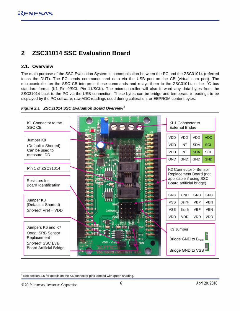
Click here to find the COM port using the resulting dialog box.
Click here to select the ZSC31014 part revision (marked on the package).
3.3. “Find Com” on the Setup Menu After installing the software and the USB drivers, activate the software. The ZSC31014 iLiteTester™ software automatically detects which type of IDT evaluation board is connected. To set up communication with the SSC CB, click on “Setup” and then “Find COM.” Click “Yes” in the resulting dialog box if the COM port selected is acceptable. If not, click “No” until an acceptable COM port is found.
If communication fails, an error message detailing the reason for failure will be displayed. For a full list of all com-munication-related error messages, see the “Error-Code” tab in SSC_CommunicationBoard_CommandSyntax_ Rev_X_x.xls.
Figure 3.1 Setting up Communications
3.4. “Change IC Rev” on the Setup Menu Use the “Change IC Rev” option on the “Setup” menu to configure the software for the silicon revision of the ZSC31014 under test as shown in Figure 3.1. Refer to the ZSC31014 package for the silicon revision.
3.5. “I2C Comm Addr” Field Use the “I2C Comm Addr” field to enter the address that the SSC CB uses to communicate with the ZSC31014 installed in the socket on the Evaluation Board. Then press “Set.” Valid settings are 00HEX to 7FHEX. The default is 28HEX.
Note: There is also a setting “I2C Addr” in the “Communication and Operation Config” section for changing the slave address setting in the EEPROM of the ZSC31014 under test described in section 4.8, which includes important notes on matching the “I2C Comm Addr” and “I2C Addr” settings when the communication address is locked.
ZSC31014 Evaluation Kit Description
© 2016 Integrated Device Technology, Inc. 10 April 20, 2016
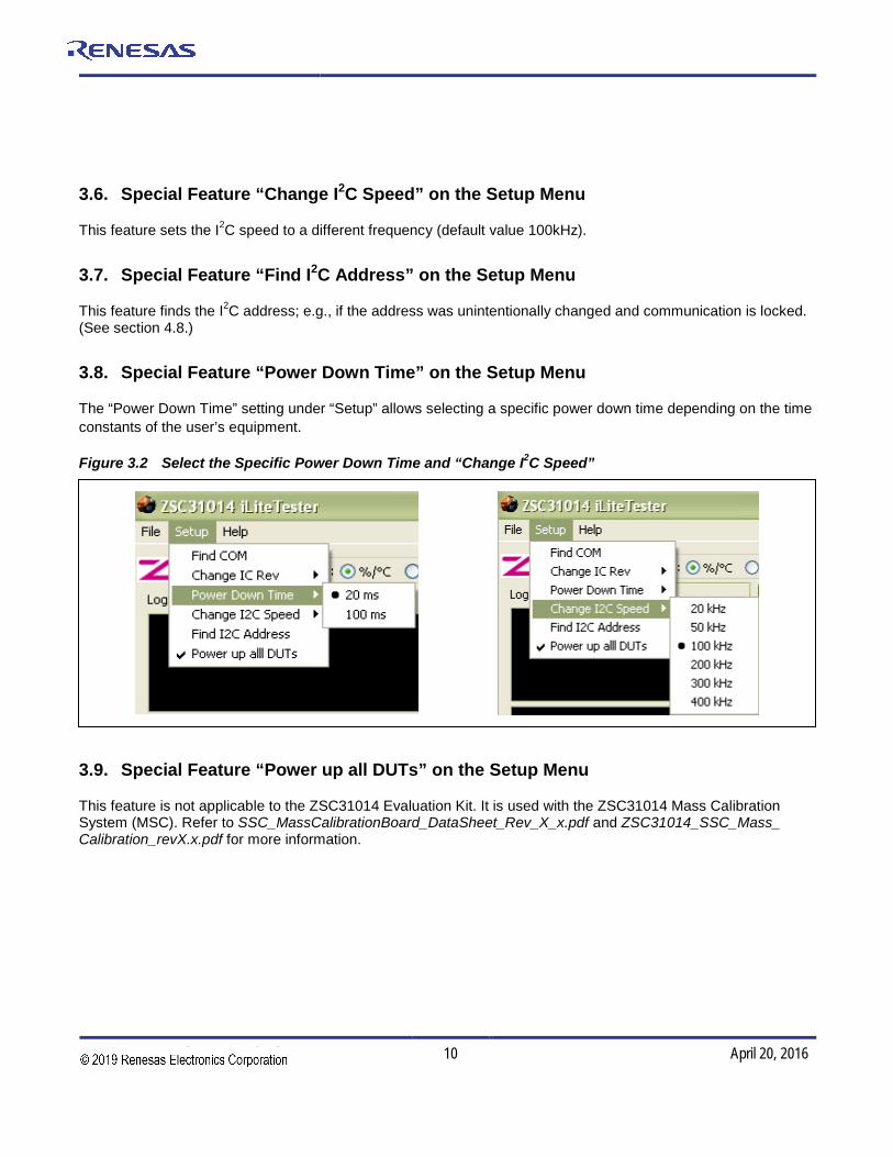
3.6. Special Feature “Change I2C Speed” on the Setup Menu
This feature sets the I2C speed to a different frequency (default value 100kHz).
3.7. Special Feature “Find I2C Address” on the Setup Menu
This feature finds the I2C address; e.g., if the address was unintentionally changed and communication is locked. (See section 4.8.)
3.8. Special Feature “Power Down Time” on the Setup Menu
The “Power Down Time” setting under “Setup” allows selecting a specific power down time depending on the time constants of the user’s equipment.
Figure 3.2 Select the Specific Power Down Time and “Change I2C Speed”
3.9. Special Feature “Power up all DUTs” on the Setup Menu
This feature is not applicable to the ZSC31014 Evaluation Kit. It is used with the ZSC31014 Mass Calibration System (MSC). Refer to SSC_MassCalibrationBoard_DataSheet_Rev_X_x.pdf and ZSC31014_SSC_Mass_ Calibration_revX.x.pdf for more information.

ZSC31014 Evaluation Kit Description
© 2016 Integrated Device Technology, Inc. 11 April 20, 2016
4 ZSC31014 iLiteTester™ Software 4.1. Overview The IDT software provided with the ZSC31014 SSC Evaluation Kit is intended for demonstration purposes and calibration of single units. The installation folder is (C:\\program files\ZMDI\ZSC31014)2. IDT can provide the user with algorithms and assistance in developing their full production calibration software. Five types of text files support the software user:
4.1.1. Log Files These files are saved in C:\\My Documents\ZMDI\ZSC31014 1
• When the software is activated and the communication port is opened, a CommLog.txt file is saved. This file is a log of the communication to the IC during the software session and can be saved after closing the software by renaming the file. Otherwise, it would be overwritten the next time the software is opened.
• In Command Mode (CM) the user can save/load the EEPROM contents from a *.eep file to the EEPROM and vise versa.
• In Normal Operation Mode (NOM) the user can log bridge and temperature readings to the DataLog.txt file.
• The calibration is documented in the CalibrationLog.txt file, which is more convenient for users than the caldata.txt file.
4.1.2. Data File caldata.txt The caldata.txt file2 is used by the software for calibration. Its structure is explained in Appendix B. Depending on the Windows system, the file is saved in one of the following locations:
• for Windows 2000 and Windows XP in C:\\Documents and Settings\All Users\Application Data\ZMDI\ZSC31014
• for Windows Vista C:\\ProgramData\ZMDI\ZSC31014
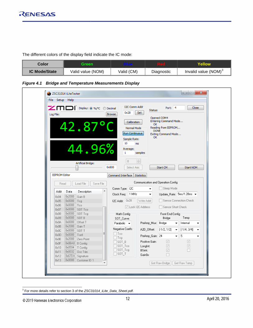
4.2. Bridge and Temperature Display The software displays two large readout windows for temperature and bridge values (see Figure 4.1). The temperature reading is the ZSC31014 temperature in oC. The bridge reading is in %. Calibration determines the relationship of the % reading to the value the bridge is measuring. If the ZSC31014 has not been temperature calibrated, the displayed temperature is invalid.
There is a continuous transmission of bridge readings and temperature readings.
2 For SW revisions <1.400, these files are stored in C:\\program files\ZMD America\ZSC31014_iLite or C:\\program
files\ZMDI\ZSC31014_iLite.
ZSC31014 Evaluation Kit Description
© 2016 Integrated Device Technology, Inc. 12 April 20, 2016
The different colors of the display field indicate the IC mode:
Color Green Blue Red Yellow
IC Mode/State Valid value (NOM) Valid (CM) Diagnostic Invalid value (NOM)3
Figure 4.1 Bridge and Temperature Measurements Display
3 For more details refer to section 3 of the ZSC31014_iLite_Data_Sheet.pdf.

ZSC31014 Evaluation Kit Description
© 2016 Integrated Device Technology, Inc. 13 April 20, 2016
The ZSC31014 is designed to be a generic resistive bridge conditioner, but for the following calibration example, assume it is connected to a pressure bridge. If the unit is calibrated to read pressure with 50kPa reading as 100% and 10kPa reading as 0%, then the span of pressure readings would be 40kPa. Half of that span (20kPa) plus the set zero point (10kPa) should be the 50% point. After calibration, if the chamber is set to 30kPa, theZSC31014 should give a 50% reading.
4.3. “Log File” Field Bridge and temperature readings can be logged to a PC file. Use the “Browse” button to select the filename and directory where the file will be stored. Then click “Open.” The “Sample Rate” field sets how often the data is col-lected. If the sample rate is 0 sec, then an entry is written for each transmission from the ZSC31014.
The resulting text file is a space-delimited ASCII file and can be imported into Microsoft Excel.
4.4. “Start CM” Button To communicate to the ZSC31014, start the Command Mode (full command set, measurement cycle stopped) by clicking “START CM” (Start Command Mode).
4.5. “Start NOM” Button To exit Command Mode and return the ZSC31014 to Normal Operation Mode (reading, conditioning and trans-mitting bridge data), click “START NOM” (Start Normal Operation Mode).
Note: For the ZSC31014, the NOM is recommended for the raw value collection during the calibration.
4.6. “Normal Mode” Section
“Run Continuous” Button To start a continuous readout of bridge and temperature data, click the “Run Continuous” button.
“Sample Rate” Field This field sets the period (ms) for the sample rate of the continuous read out. Valid settings are 10ms or longer.
“Average Samples” Field This feature allows averaging the measured values by choosing the number of samples to average before displaying the result. Note this is a running average, so increasing the number to average increases the display’s settling time but does not affect the update rate.
ZSC31014 Evaluation Kit Description
© 2016 Integrated Device Technology, Inc. 14 April 20, 2016
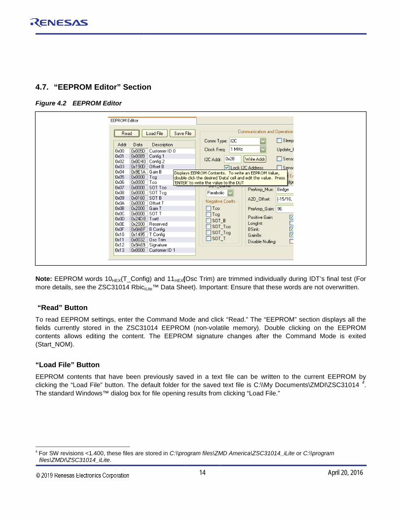
4.7. “EEPROM Editor” Section
Figure 4.2 EEPROM Editor
Note: EEPROM words 10HEX(T_Config) and 11HEX(Osc Trim) are trimmed individually during IDT’s final test (For more details, see the ZSC31014 RbiciLite™ Data Sheet). Important: Ensure that these words are not overwritten.
“Read” Button To read EEPROM settings, enter the Command Mode and click “Read.” The “EEPROM” section displays all the fields currently stored in the ZSC31014 EEPROM (non-volatile memory). Double clicking on the EEPROM contents allows editing the content. The EEPROM signature changes after the Command Mode is exited (Start_NOM).
“Load File” Button EEPROM contents that have been previously saved in a text file can be written to the current EEPROM by clicking the “Load File” button. The default folder for the saved text file is C:\\My Documents\ZMDI\ZSC31014 4. The standard Windows™ dialog box for file opening results from clicking “Load File.”
4 For SW revisions <1.400, these files are stored in C:\\program files\ZMD America\ZSC31014_iLite or C:\\program
files\ZMDI\ZSC31014_iLite.

ZSC31014 Evaluation Kit Description
© 2016 Integrated Device Technology, Inc. 15 April 20, 2016
“Save File” Button The EEPROM contents can be saved in a text file in the C:\\My Documents\ZMDI\ZSC31014 directory 5 by clicking the “Save File” button. The standard Windows™ dialog box for file saving results.
4.8. “Communication and Operation Config” Section
This section is used to expedite programming configuration and communication settings in the EEPROM of the ZSC31014 under test.
“Comm Type” Menu Three communication options are available on the “Comm Type” drop-down menu:
• I2C
• SPI (pos edge): SPI / MISO changes on positive edge clock frequency
• SPI (neg edge): SPI / MISO changes on negative edge clock frequency
“Clock Freq” Menu Select 1MHz or 4MHz for the clock frequency for the ZSC31014 using the “Clock Freq” drop-down menu. The lower clock frequency (1MHz) is the recommend selection for lower power and better noise performance. If faster response time is required, the 4MHz clock frequency setting is needed.
“I2C Addr” Field When the ZSC31014 is in I2C communication mode, the default slave address is 28HEX. If a different slave address is required, program the part for the new address by entering the hex value of the new address in the “I2C Addr” field and then click “Write Addr.” The valid address range is 00HEX to 7FHEX.
Note: If the “Lock I2C Address” is on (see below), “I2C Addr” must match the “I2C Comm Addr” setting (see section 3.5).
“Lock I2C Address” Checkbox Lock the slave address selection by clicking “Lock I2C Address” checkbox. Without this lock, the IC will respond to all I2C addresses.
“Sleep Mode” Checkbox To select the Sleep Mode, click on the “Sleep Mode” checkbox; otherwise, the Update Rate Mode is selected as the default mode. The Sleep Mode enables the most power saving mode of the ZSC31014.
5 For SW revisions <1.400, these files are stored in C:\\program files\ZMD America\ZSC31014_iLite or C:\\program
files\ZMDI\ZSC31014_iLite.

ZSC31014 Evaluation Kit Description
© 2016 Integrated Device Technology, Inc. 16 April 20, 2016
“Update_Rate” Menu When operating in Update Mode, the update rate determines power consumption and response time. Select the update rate by clicking on one of the four update rates on the “Update_Rate” drop-down menu.
“Sensor Short Check” Checkbox To enable the sensor short diagnostic, click on the “Sensor Short Check” checkbox.
“Sensor Connection Check” Checkbox To enable the sensor open diagnostic, click on the “Sensor Connection Check” checkbox.
Note This check must be disabled when using the modular Sensor Replacement Board for evaluation. Its dummy bridge is actually only a half bridge and will always report a diagnostic case. For more details refer to the ZSC31014 RbiciLite™ Data Sheet.
4.9. Math Config Section
“SOT_Curve” Menu Some sensors perform better when compensated with a second order term (SOT) based on a zero-point symmetrical output function6 (S-shaped) instead of the parabolic curve function used to compensate more common sensors. The curve type is controlled by SOT_Curve (bit 9 in EEPROM word 01HEX). Select the curve type from the “SOT_Curve” drop-down menu. When the S-shaped curve is selected, the zero point is in the middle of the output and a negative and positive output signal can be compensated using only the 2nd order term.
“Negative Coeffs” Subsection The Tco, Tcg, SOT_Bridge, SOT_Tco, SOT_Tcg and SOT_T checkboxes in the “Negative Coeffs” section indicate the sign of the calculated calibration coefficients after calibration.
4.10. “Front End Config” Section In the “Front End Config” section, select the configuration for the AFE (Analog Front End) as determined from the bridge sensor performance before starting calibration. The configuration for the temperature depends on the choice of an internal or external temperature sensor. For the internal sensor, a default calibration word is configured. Additional selections are available in the “Calibration/Set ASIC Configuration” window (click “Calibration” to initialize).
Note: The Excel™ file ZSC31014_AFE_Configuration.xls can be used to determine the correct adjustment of the analog PreAmp gain and the analog A2D offset modes based on the known sensor characteristics. The Excel™sheet ZSC31014_iLite_ext_Temperaturemeasurement.xls can be used to determine the configuration for external temperature sensors.
6 For the ZSC31014 RBiciLite revision A, only the parabolic curve is usable.
ZSC31014 Evaluation Kit Description
© 2016 Integrated Device Technology, Inc. 17 April 20, 2016
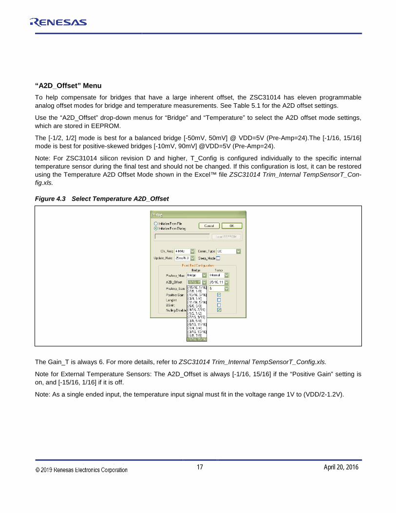
“A2D_Offset” Menu To help compensate for bridges that have a large inherent offset, the ZSC31014 has eleven programmable analog offset modes for bridge and temperature measurements. See Table 5.1 for the A2D offset settings.
Use the “A2D_Offset” drop-down menus for “Bridge” and “Temperature” to select the A2D offset mode settings, which are stored in EEPROM.
The [-1/2, 1/2] mode is best for a balanced bridge [-50mV, 50mV] @ VDD=5V (Pre-Amp=24).The [-1/16, 15/16] mode is best for positive-skewed bridges [-10mV, 90mV] @VDD=5V (Pre-Amp=24).
Note: For ZSC31014 silicon revision D and higher, T_Config is configured individually to the specific internal temperature sensor during the final test and should not be changed. If this configuration is lost, it can be restored using the Temperature A2D Offset Mode shown in the Excel™ file ZSC31014 Trim_Internal TempSensorT_Con-fig.xls.
Figure 4.3 Select Temperature A2D_Offset
The Gain_T is always 6. For more details, refer to ZSC31014 Trim_Internal TempSensorT_Config.xls.
Note for External Temperature Sensors: The A2D_Offset is always [-1/16, 15/16] if the “Positive Gain” setting is on, and [-15/16, 1/16] if it is off.
Note: As a single ended input, the temperature input signal must fit in the voltage range 1V to (VDD/2-1.2V).

ZSC31014 Evaluation Kit Description
© 2016 Integrated Device Technology, Inc. 18 April 20, 2016
“PreAmp_Gain” Menu The ZSC31014 PreAmp amplifies the bridge signal to produce the differential signal that will be converted by the ADC. The PreAmp has eight possible analog gain settings: 1.5, 3, 6, 12, 24 (default), 48, 96, and 1927. Use the “PreAmp_Gain” drop-down menus for “Bridge” and “Temperature” to select the PreAmp gain settings, which are stored in EEPROM. (Note: This term is different from the digital gain terms Gain_B and Gain_T, which are multiplied by the result of the ADC to compensate sensor span for bridge and temperature measurements.)
Any bridge input signal greater than 40mV/V in differential mode will saturate the pre-amp if the gain is set to 24 (default). In this case, the pre-amp gain must be set to the lower value 12.
For very small differential input signals, the higher analog gain (e.g., 40) can improve the output resolution (see section 1.4 in the data sheet), but the sensor offset must always be considered as well as sensor span. Both the offset and span of the sensor are amplified by the pre-amp. With a high analog gain (48), the total offset plus span cannot exceed 20mV/V differential. Otherwise the input to the ADC will be saturated.
Note for External Temperature Sensors: The PreAmp_Gain is usually set to 3 or 5, which always guarantees the specified resolution.
Note: As a single ended input, the temperature input signal must fit in the voltage range 1V to (VDD/2-1.2V).
“Negative” Checkbox To select negative bridge gain polarity, click on the “Negative” checkbox.
“LongInt” Checkbox To select the longer conversion time for low noise, click on the “LongInt” checkbox. (For more details see the ZSC31014 RbiciLite™ Data Sheet.)
“Bsink” Checkbox To enable the Bsink power-saving option, click on the “Bsink” checkbox.
“Gain8X” Checkbox If “Gain8X_B” is checked, the Gain_B is multiplied by a factor of 8. The check box is set by the calibration DLL as result of the calculated calibration coefficients stored in the EEPROM.
4.11. “Calibration” Button To initiate a calibration run, click the “Calibration” button. This results in the calibration screen and dialog box shown in Figure 4.4. See section 5 for a full description of calibration and settings used on the “Calibration” window.
7 For the previous silicon revision (A), the PreAmp gain settings were 1, 3, 5, 15, 24 (default), 40, 72, and 120.
ZSC31014 Evaluation Kit Description
© 2016 Integrated Device Technology, Inc. 19 April 20, 2016
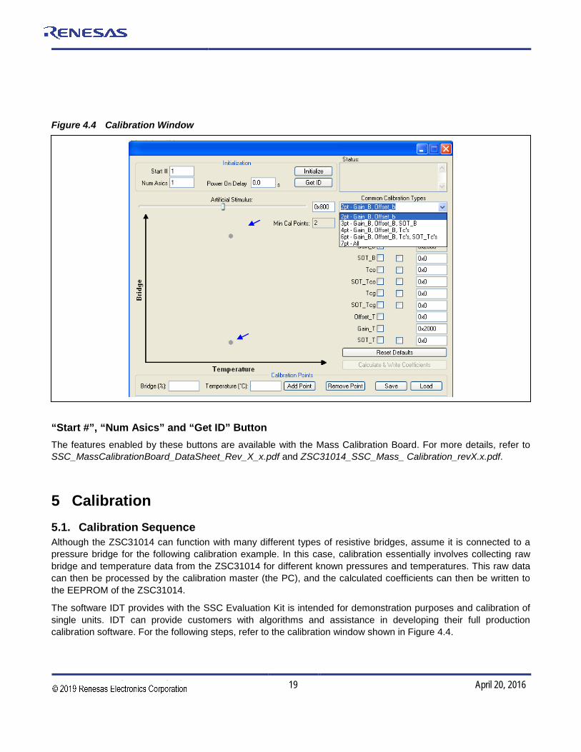
Figure 4.4 Calibration Window
“Start #”, “Num Asics” and “Get ID” Button The features enabled by these buttons are available with the Mass Calibration Board. For more details, refer to SSC_MassCalibrationBoard_DataSheet_Rev_X_x.pdf and ZSC31014_SSC_Mass_ Calibration_revX.x.pdf.
5 Calibration 5.1. Calibration Sequence Although the ZSC31014 can function with many different types of resistive bridges, assume it is connected to a pressure bridge for the following calibration example. In this case, calibration essentially involves collecting raw bridge and temperature data from the ZSC31014 for different known pressures and temperatures. This raw data can then be processed by the calibration master (the PC), and the calculated coefficients can then be written to the EEPROM of the ZSC31014.
The software IDT provides with the SSC Evaluation Kit is intended for demonstration purposes and calibration of single units. IDT can provide customers with algorithms and assistance in developing their full production calibration software. For the following steps, refer to the calibration window shown in Figure 4.4.
ZSC31014 Evaluation Kit Description
© 2016 Integrated Device Technology, Inc. 20 April 20, 2016
Click here to access the initialization dialog box.
For rev D, the setting for the internal diode will not be changed by the software
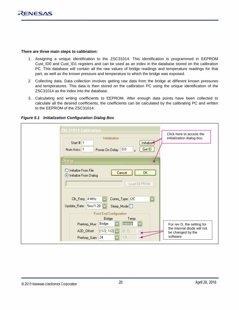
There are three main steps to calibration:
1. Assigning a unique identification to the ZSC31014. This identification is programmed in EEPROM Cust_ID0 and Cust_ID1 registers and can be used as an index in the database stored on the calibration PC. This database will contain all the raw values of bridge readings and temperature readings for that part, as well as the known pressure and temperature to which the bridge was exposed.
2. Collecting data. Data collection involves getting raw data from the bridge at different known pressures and temperatures. This data is then stored on the calibration PC using the unique identification of the ZSC31014 as the index into the database.
3. Calculating and writing coefficients to EEPROM. After enough data points have been collected to calculate all the desired coefficients, the coefficients can be calculated by the calibrating PC and written to the EEPROM of the ZSC31014.
Figure 5.1 Initialization Configuration Dialog Box

ZSC31014 Evaluation Kit Description
© 2016 Integrated Device Technology, Inc. 21 April 20, 2016
Step 1 – Assigning a Unique Identification (ASIC ID Section) In the top middle of the calibration screen (see Figure 4.4), click on “Initialize.” In the resulting dialog box (see Figure 5.1), verify or correct the configuration for the ZSC31014 under test and then click OK to initialize the part. The part is assigned a unique ID, which is used as an index in the database. This unique ID is also programmed into the EEPROM Cust_ID0 and Cust_ID1 registers. The software automatically loads and writes unity values for Gain_B and Gain_T to the EEPROM and sets the Offset_B to an A2D_Offset related value. All other coefficients are set to zero. The raw data are collected with these settings in NOM.
Note: The default values shown in this dialog window are the previous settings and can differ from the actual EEPROM contents, which will be overwritten by clicking the OK button.
Step 2 – Data Collection “Common Calibration Type” Menu
Next, select the type of calibration required from the “Common Calibration Type” pull-down menu in the top right of the calibration screen (see Figure 5.1). The number of unique points (for this example, pressure and tempera-ture points) at which calibration must be performed depends on the user’s requirements. The minimum is a 2-point calibration, and the maximum is a 7-point calibration.
Depending on the number of calibration temperature points, a linear or second order temperature correction is performed with 2 or 3 (respectively) temperature coefficients (Offset_T&Gain_T or Offset_T&Gain_T&SOT_T).
In the left section of the calibration screen (see Figure 4.4), there is a graph (X-axis = Temperature, Y-axis = Bridge). This graph outlines the recommended spread of points (pressure for this example and temperature) to be used for calibration.
Based on statistical sensor measurements, a customer can decide to reduce the calibration costs by setting user-selected default values for various calibration coefficients instead of using the calibration measurements. In this case, enter the default values to be used for the selected calibration method in the coefficient entry fields at the right of the calibration screen (see Figure 4.4). These fields will not be calculated by the chosen calibration method. The calculation is disabled if there are entries for all defaults.
“Reset Defaults” Button
If needed, clicking the “Reset Defaults” button sets the default coefficients to 00HEX except Gain_B/Gain_T, which are set to unity (2000HEX) and Offset_B, which is set to a value related to the ADC offset (A2D_Offset setting). See Table 5.1.
Table 5.1 Offset_B Default Values Determined by A2D_Offset Settings
A2D Input Range [VREF] A2D_Offset Offset_B(hex)
-15/16 to 1/16 15/16 1C00HEX
-7/8 to 1/8 7/8 1800HEX
-13/16 to 3/16 13/16 1400HEX
-3/4 to 1/4 3/4 1000HEX
-11/16 to 5/16 11/16 0C00HEX

ZSC31014 Evaluation Kit Description
© 2016 Integrated Device Technology, Inc. 22 April 20, 2016
A2D Input Range [VREF] A2D_Offset Offset_B(hex)
-5/8 to 3/8 5/8 0800HEX
-9/16 to 7/16 9/16 0400HEX
-1/2 to 1/2 1/2 0000HEX
-7/16 to 9/16 7/16 FC00HEX
-3/8 to 5/8 3/8 F800HEX
-5/16 to 11/1 5/16 F400HEX
-1/4 to 3/4 1/4 F000HEX
-3/16 to 13/16 3/16 EC00HEX
-1/8 to 7/8 1/8 E800HEX
-1/16 to 15/16 1/16 E400HEX
“Bridge (%)” and “Temperature (°C)” Fields
Place the bridge/ZSC31014 pair to be calibrated in a controlled environment (for this example, a pressure and temperature chamber), and stabilize the environment at the first desired calibration point.
→ Enter the target bridge readout in % (in this case, pressure) in the “Bridge (%)” field under “Actual.” (See Figure 5.1.)
→ Enter the target temperature in °C in the “Temperature (°C)” field under “Actual.”
→ Click on “Add New Point.” The raw data (pressure and temperature) are obtained from the part, and the point is displayed on the large graph. The point is graphed as the values entered in the previous two steps: the X-axis is the target temperature reading and the Y-axis is the target % value.
→ Change the pressure/temperature of the bridge/ZSC31014 pair being calibrated and repeat. Take as many more points as needed.
Hints:
For good calibration results, choose the temperature and bridge readout (%) values as close as possible to the desired working range.
Step 3 – Calculating and Writing the Coefficients “Calculate & Write Coefficients” Button
After enough data points have been collected to calculate the calibration coefficients, click the “Calculate & Write Coefficients” button. The software calculates all the coefficients, writes them to EEPROM, and frees up that index for future use. The bridge/IC pair is now calibrated. Before the software starts to calculate and write the coefficients, all raw readings are stored in the caldata.txt file (see section 4.1.2).
ZSC31014 Evaluation Kit Description
© 2016 Integrated Device Technology, Inc. 23 April 20, 2016
Internal diode settings except “LongInt” should not be changed by the software (see data sheet for more details)
5.2. Dry Run Calibration The following steps demonstrate a simple 2-point linear calibration using the artificial bridge on the Evaluation Board. Important: The jumpers must be connected on K6 (VBP) and K7 (VNP).
Steps for a Dry Run Calibration using the Artificial Bridge on the Evaluation Board:
1. Connect the SSC Communication (SSC CB) and the SSC ZSC31014 Evaluation Board. Insert the ZSC31014 in the SOP-8 socket on the SSC Evaluation Board. The correct orientation for pin 1 is shown in Figure 2.1.
2. Connect a USB cable from the USB connector on the SSC CB to an available USB port on the PC. Verify that the green PWR LED is lit on the SSC CB.
3. Start the ZSC31014 iLiteTester™ software.
4. Click “Find Port” to find the proper COM port.
5. Click on “START CM.” If the setup is correct, the buttons in the lower part of the main window will be activated.
6. Click on “Calibration.” The calibration window appears (Figure 4.4).
7. In the upper right section of the calibration window, under the “Common Calibration Types” drop-down menu, choose “2-Pt Gain_B, Offset_B” calibration. The graph indicates the recommended pattern of two bridge readings at the same temperature.
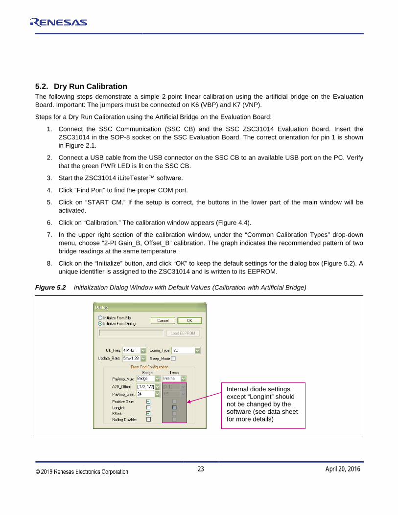
8. Click on the “Initialize” button, and click “OK” to keep the default settings for the dialog box (Figure 5.2). A unique identifier is assigned to the ZSC31014 and is written to its EEPROM.
Figure 5.2 Initialization Dialog Window with Default Values (Calibration with Artificial Bridge)

ZSC31014 Evaluation Kit Description
© 2016 Integrated Device Technology, Inc. 24 April 20, 2016
9. The next step is to start data collection. Normally this would be done with a real bridge attached to the ZSC31014 on a remote board in a controlled chamber. Instead, this dry run calibration uses the artificial bridge inputs controlled by the on-board DAC. The DAC is controlled by the “Artificial Stimulus” slider bar or its adjacent entry field at the top of the calibration window (see Figure 4.4).
a. Set the DAC control to 300HEX. b. Enter 10 in the “Bridge (%)” field under “Actual.” c. Click on “Add New Point.” The software obtains a raw reading from the part and graphs the new data
point. d. Change the DAC setting to D00HEX. e. Enter 90 in the “Bridge (%)” field under “Actual.” f. Click on “Add New Point” again. The software obtains a new raw reading from the part and graphs
the new data point. 10. Because this is a 2-point calibration, the software has all the necessary data for calculating and writing
the coefficients. Click on “Calculate & Write Coefficients,” which should now be active.
11. Close the calibration window. The temperature reading is not valid because not enough data points were collected for temperature calibration.
12. Start the Normal Operation Mode (NOM) by clicking on “START NOM” and read the measurement results continuously (click Run Continuous).The DAC is now controlled by the “Artificial” slider below the data read-outs and its adjacent entry field. Adjust the DAC, and check that the displayed values make sense. For example, 800HEX should read 50% and A80HEX should read 70%.
Steps for a Dry Run Calibration using the Sensor Replacement Board: The following steps demonstrate a simple 2-point linear calibration using the artificial bridge on the Sensor Replacement Board (SRB).
Important: The jumpers must be removed from connectors K6 (VBP) and K7 (VNP).
1. Connect the SSC Communication (SSC CB), the SSC ZSC31014 Evaluation Board and SSC SRB. Insert the ZSC31014 in the SOP-8 socket on the SSC Evaluation Board. The correct orientation for pin 1 is shown in Figure 2.1.
2. Connect a USB cable from the USB connector on the SSC CB to an available USB port on the PC. Verify that the green PWR LED is lit on the SSC CB.
3. Start the iLiteTester™ software.
4. Click “Find Port” to find the proper COM port.
5. Click on “START CM.” If the setup is correct, the buttons in the lower part of the main window will be activated.
6. Click on “Calibration.” The calibration window appears (Figure 4.4).
7. In the upper right section of the calibration window, under the “Common Calibration Types” drop-down menu, choose “2-Pt Gain_B, Offset_B” calibration. The graph indicates the recommended pattern of two bridge readings at the same temperature.
ZSC31014 Evaluation Kit Description
© 2016 Integrated Device Technology, Inc. 25 April 20, 2016
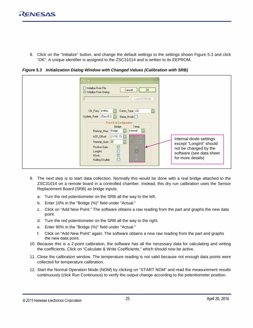
8. Click on the “Initialize” button, and change the default settings to the settings shown Figure 5.3 and click “OK”. A unique identifier is assigned to the ZSC31014 and is written to its EEPROM.
Figure 5.3 Initialization Dialog Window with Changed Values (Calibration with SRB)
9. The next step is to start data collection. Normally this would be done with a real bridge attached to the ZSC31014 on a remote board in a controlled chamber. Instead, this dry run calibration uses the Sensor Replacement Board (SRB) as bridge inputs.
a. Turn the red potentiometer on the SRB all the way to the left. b. Enter 10% in the “Bridge (%)” field under “Actual.” c. Click on “Add New Point.” The software obtains a raw reading from the part and graphs the new data
point. d. Turn the red potentiometer on the SRB all the way to the right. e. Enter 90% in the “Bridge (%)” field under “Actual.” f. Click on “Add New Point” again. The software obtains a new raw reading from the part and graphs
the new data point. 10. Because this is a 2-point calibration, the software has all the necessary data for calculating and writing
the coefficients. Click on “Calculate & Write Coefficients,” which should now be active.
11. Close the calibration window. The temperature reading is not valid because not enough data points were collected for temperature calibration.
12. Start the Normal Operation Mode (NOM) by clicking on “START NOM” and read the measurement results continuously (click Run Continuous) to verify the output change according to the potentiometer position.
Internal diode settings except “LongInt” should not be changed by the software (see data sheet for more details)

ZSC31014 Evaluation Kit Description
© 2016 Integrated Device Technology, Inc. 26 April 20, 2016
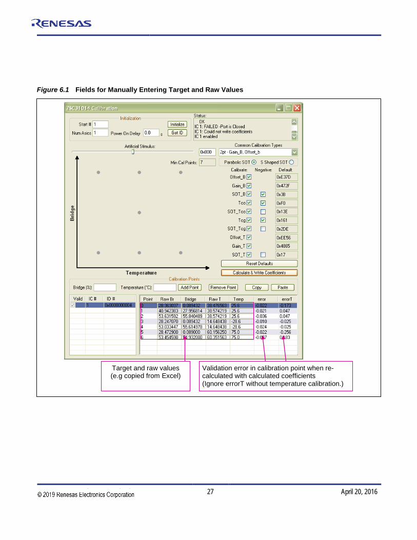
6 Calculation of ZSC31014 Calibration Coefficients Off-line Note This calculation is possible without connecting the kit boards to the PC. Raw and target values can copied using the copy and paste function of Microsoft Office from an Excel™ table for software revisions 1.420 and higher.
Steps for the Off-line Calibration Coefficient Calculation: (1) Start the ZSC31014 cLite™ Software. (2) Click on “Calibrate.” The calibration window appears (see Figure 6.1). (3) Select the coefficients for the desired calibration method by highlighting the coefficients in the upper middle
section of the calibration window. The smaller graph above the coefficient list indicates the recommended pattern of capacitive sensor readings and temperature readings.
(4) Click on “Initialize” in the “Initialization” section (upper left corner). The “Initialize Calibration” window appears (see Figure 5.2). Click “Browse” and select any xxx.eep file stored in the folder C:\Documents And Settings\[Current User]\My Documents\ZMDI\ZSC31014. Click on “Initialize From File.” Note: This is a “blind” initialization, because no part is connected.
(5) Start data collection. Fill in numbers in the column “Point”. The target and raw values can be written/copied in the related fields. The numbers are [%] for the bridge target and raw readings and [°C] for the temperature target and raw readings.
a. Click on “Add New Point.” b. Enter the first target bridge reading [%] in the “sensor” field and enter the raw value [%] in the “raw”
field. For calibration with temperature compensation, also add the chamber temperature in the “temp” field temperature and raw readings in the “rawT” fields.
c. Repeat a) and b) as needed until all calibration points are entered.
(6) Check the “Valid” check box, and click on the “Calculate Coefficients“button. The coefficients are stored in the CalibrationLog.txt file.
(7) Click “View Log” to open this file. For each calibration point, the error for the point is calculated in the same file.
Note Instead of entering the raw and target values for the bridge and temperature target and raw values, these values can be transferred from an Excel™ file using the copy/paste feature. First, add the correct number of calibration points ( correct table size). Make sure that the Excel™ table includes only numbers in the correct format (Category: Number). Copying from formula results is not possible.
The minimum number of points is determined by the selected calibration method. Additional points can be added. If the points are selected (check box enabled), they will be part of the calibration; otherwise these points will be used for error validation only.
ZSC31014 Evaluation Kit Description
© 2016 Integrated Device Technology, Inc. 27 April 20, 2016
Target and raw values (e.g copied from Excel)
Validation error in calibration point when re-calculated with calculated coefficients (Ignore errorT without temperature calibration.)
Figure 6.1 Fields for Manually Entering Target and Raw Values

ZSC31014 Evaluation Kit Description
© 2016 Integrated Device Technology, Inc. 28 April 20, 2016
7 ZSC31014 Software with the IDT SSC Terminal 7.1. Protocol The microcontroller (type Atmega32) on the SSC Communication Board (SSC CB) enables communication with the SSC Evaluation Board and the ZSC31014 using the evaluation software running on the PC. The standard l2C protocol is implemented in the microcontroller’s software. The USB_UART IC on the SSC CB transfers the signals from the microcontroller to the USB port of the PC.
For more details, see SSC_CommunicationBoard_CommandSyntax_Rev_X_x.xls.
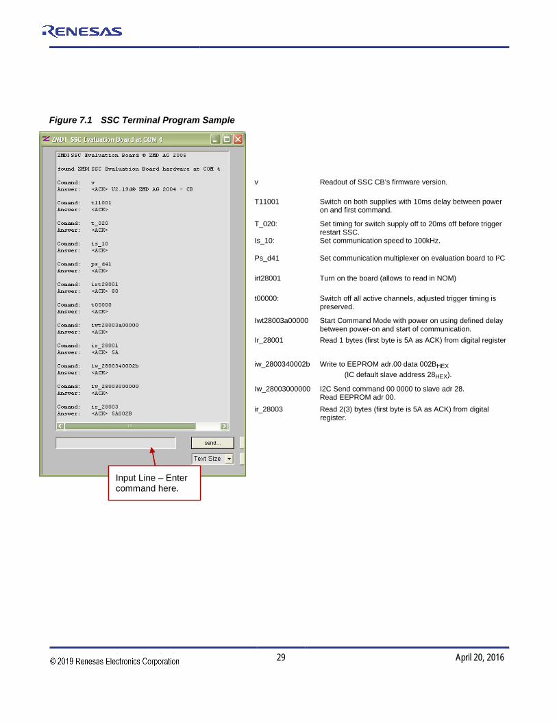
7.2. IDT SSC Terminal The IDT SSC Terminal is the lowest level of communication for transferring commands from the PC to the microcontroller on the SSC CB. A fully summary and detailed command description of the applicable controller commands are given in SSC_CommunicationBoard_CommandSyntax_Rev_X_x.xls.
Install the SSC Terminal V201.exe from the SSC CD-ROM, which will create a IDT SSC Terminal icon on the PC desktop. Click on this icon to active the terminal program. For the ZSC31014 communication mode, use the setting explained for I2C (bi-directional) or SPI (only reading).
Table 7.1 IDT SSC Terminal Character Assignment
Character Order
1 2 3 4,5 6,7,8 <d…d> ZSC31014 I R or W T or _
Comments Read or Write
Trigger Power Cycle or Not
Slave address ) (28h default)
Number of Bytes to Read and Write
Blank for Read; Data Bytes to Write
Examples I W T 28 003 500000 I R _ 28 002
Hint: If “T” is sent for the 3rd position (instead of “_”), the ZSC31014 is powered off and then on. “T” should be used only if power cycling is necessary for operation.
Figure 7.1 shows a communication example. Write the command in the input line and press ENTER on the keyboard or click on “Send.”
ZSC31014 Evaluation Kit Description
© 2016 Integrated Device Technology, Inc. 29 April 20, 2016
Figure 7.1 SSC Terminal Program Sample
v Readout of SSC CB’s firmware version.
T11001 Switch on both supplies with 10ms delay between power on and first command.
T_020: Set timing for switch supply off to 20ms off before trigger restart SSC.
Is_10: Set communication speed to 100kHz.
Ps_d41 Set communication multiplexer on evaluation board to I²C
irt28001 Turn on the board (allows to read in NOM)
t00000: Switch off all active channels, adjusted trigger timing is preserved.
Iwt28003a00000 Start Command Mode with power on using defined delay between power-on and start of communication.
Ir_28001 Read 1 bytes (first byte is 5A as ACK) from digital register
iw_2800340002b Write to EEPROM adr.00 data 002BHEX (IC default slave address 28HEX).
Iw_28003000000 I2C Send command 00 0000 to slave adr 28. Read EEPROM adr 00.
ir_28003 Read 2(3) bytes (first byte is 5A as ACK) from digital register.
Input Line – Enter command here. Input Line – Enter command here.

ZSC31014 Evaluation Kit Description
© 2016 Integrated Device Technology, Inc. 30 April 20, 2016
8 Command/Data Pair Encoding See the current version of the ZSC31014_iLite_Data_Sheet document for more details on commands and for the assignment of the EEPROM bits.
In Command Mode, the master uses the I2C protocol to send 4-byte commands to the Rbiciite™. This 32-bit I2C packet command/data stream consists of a I2C WRITE command byte, which is the 7-bit slave address followed by the write bit 0 (e.g., 50HEX = I2C WRITE command byte for the default slave address 28HEX and write bit 0); then a command byte; and then16 data bits. See the ZSC31014_iLite_Data_Sheet document for a detailed illustration of the WRITE command packet. Table 8.1 gives the format and valid range for the three bytes that follow the initial I2C WRITE command byte.
Note: Only the commands listed in Table 8.1 are valid for the ZSC31014 in Command Mode. Other encodings might cause unpredictable results. If data is not needed for the command, zeros must be supplied as data to complete the 32-bit packet.
Table 8.1 Encoding for the 3 Bytes after the Initial I2C WRITE Command Byte
Command Byte (Second Byte)
8 Command Bits (Hex)
Third and Fourth Bytes
16 Data Bits(Hex) Description
00HEX to 13HEX 0000HEX EEPROM Read of addresses 00HEX to 13HEX. After this command has been sent and executed, a data fetch of three bytes must be performed. The first byte will be a response byte, which should be a 5AHEX, and then the next two bytes will be the EEPROM data.
40HEX to 53HEX YYYYHEX (Y= data)
Write to EEPROM addresses 00HEX to 13HEX. If the command is an EEPROM write, then the 16 bits of data sent will be written to the address specified in the 6 LSBs of the command byte.
80HEX 0000HEX Start_NOM => Ends Command Mode and transitions to Normal Operation Mode. When a Start_NOM command is executed, a flag is checked to see if EEPROM was programmed during Command Mode. If so, the device will regenerate the checksum and update the signature EEPROM word.
A0HEX 0000HEX Start_CM => Start Command Mode; used to enter the command interpreting mode. Start_CM is only valid during the power-on command window.

ZSC31014 Evaluation Kit Description
© 2016 Integrated Device Technology, Inc. 31 April 20, 2016
9 Related Documents Document
ZSC31014 RbiciLite™ Data Sheet
ZSC31014 RbiciLite Technical Notes—Die Dimensions and Pad Coordinates
ZSC31014 Internal Temperature Sensor Trim Spreadsheet (T_Config) *
ZSC31014 RbiciLite Technical Notes—Calibration Sequence and Calibration DLL
ZSC31014 RbiciLite Spreadsheet for External Temperature Sensor Calculations
SSC Sensor Replacement Board Data Sheet
SSC Application Note – Communication Board Driver Installation.
SSC Evaluation Kits Feature Sheet (includes ordering codes and price information)
SSC Communication Board Datasheet
Command Syntax Spreadsheet for ZSC31xxx and ZSSC3xxx Products
Visit IDT’s website www.IDT.com or contact your nearest sales office for the latest version of these documents, except files marked with an asterisk, which are available on request.
10 Glossary Term Description
ADC Analog-to-Digital Converter
CMC Calibration Microcontroller
CMV Common Mode Voltage
SCC Sensor Connection Check
SSC Sensor Signal Conditioner

ZSC31014 Evaluation Kit Description
© 2016 Integrated Device Technology, Inc. 32 April 20, 2016
11 Document Revision History Revision Date Description
1.2 11-Mar-10 Revision for Table 5.1.
1.21 30-Jun-10 Updated Terminal Example
1.3 28-July-10 Revised product name from ZMD31014 to ZSC31014.
1.4 18-Mar-11 Added sections 2.5, 2.6 and 6; revised pictures according to the software changes. Reorganized sections 2 and 3. Added section 4.3. Reorganized sections 2 and 3. Replaced Appendix C for error codes with reference in section 3.3 to the error code tab in the command syntax document. Updated file names for related documents. Clarified that ZSC31014_Trim _Internal TempSensor T_Config_revX.x.xls is available on request.
1.50 11-Jul-2012 Updated for new Evaluation Board, which now has a 2-pin connector (K9) for measuring IDD. Updated text regarding jumper on new connector. Updated contact information.
April 20, 2018 Changed to IDT branding.
ZSC31014 Evaluation Kit Description
© 2016 Integrated Device Technology, Inc. 33 April 20, 2016
20K
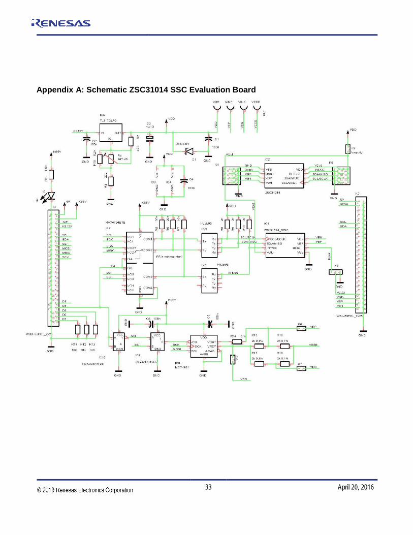
Appendix A: Schematic ZSC31014 SSC Evaluation Board
ZSC31014 Evaluation Kit Description
© 2016 Integrated Device Technology, Inc. 34 April 20, 2016
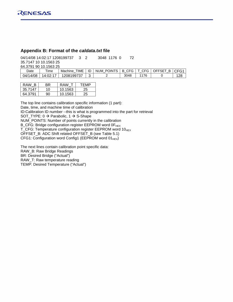
Appendix B: Format of the caldata.txt file 04/14/08 14:02:17 1208199737 3 2 3048 1176 0 72 35.7147 10 10.1563 25 64.3791 90 10.1563 25
Date Time Machine_TIME ID NUM_POINTS B_CFG T_CFG OFFSET_B CFG1 04/14/08 14:02:17 1208199737 3 2 3048 1176 0 128
RAW_B BR RAW_T TEMP 35.7147 10 10.1563 25 64.3791 90 10.1563 25
The top line contains calibration specific information (1 part): Date, time, and machine time of calibration ID:Calibration ID number --this is what is programmed into the part for retrieval SOT_TYPE: 0 Parabolic, 1 S-Shape NUM_POINTS: Number of points currently in the calibration B_CFG: Bridge configuration register EEPROM word 0FHEX T_CFG: Temperature configuration register EEPROM word 10HEX OFFSET_B: ADC Shift related OFFSET_B (see Table 5.1) CFG1: Configuration word Config1 (EEPROM word 01HEX)
The next lines contain calibration point specific data: RAW_B: Raw Bridge Readings BR: Desired Bridge (“Actual”) RAW_T: Raw temperature reading TEMP: Desired Temperature (“Actual”)

20
Corporate HeadquartersTOYOSU FORESIA, 3-2-24 Toyosu,Koto-ku, Tokyo 135-0061, Japanwww.renesas.com
Contact InformationFor further information on a product, technology, the most up-to-date version of a document, or your nearest sales office, please visit:www.renesas.com/contact/
TrademarksRenesas and the Renesas logo are trademarks of Renesas Electronics Corporation. All trademarks and registered trademarks are the property of their respective owners.