Embed Size (px)
Citation preview
Evaluates: MAX5216 MAX5216DACLite Evaluation Kit
Component List
General DescriptionThe MAX5216DACLite evaluation kit (EV kit) enables evaluation of the MAX5216 single-channel, low-power, buffered-output, 3-wire SPI interface, 16-bit DAC. The EV kit also includes Windows XPM-, Windows VistaM-, and
WindowsM 7-compatible software that provide a simple graphical user interface (GUI) for exercising the features of the IC.The EV kit enables a quick evaluation of the device, with a fixed supply voltage of 3.3V. The EV kit allows for the generation of selectable waveforms to display DAC AC signal-generation capability.The EV kit can be used as a system hardware debugging tool, or as a signal generator demonstration kit.
Features USBPowered,NoAdditionalSupplyNeeded*
(CableNotIncluded) 3.3VFixedVDDfromOn-BoardLDO(MAX8510) 3.000VOn-BoardPreciseVoltageReference
(MAX6133) DirectUSBCommunicationthroughtheMAXQ622
Microcontroller WindowsXP-,WindowsVista-,andWindows7
(32-Bit)-CompatibleSoftware SPIInterfaceTerminals ProvenPCBLayout FullyAssembledandTested
19-6527; Rev 0; 11/12
Ordering Information appears at end of data sheet.
Windows XP, Windows Vista, and Windows are registered trademarks and registered service marks of Microsoft Corporation.
*Since 16 bits is 65,535 levels, the LSB is 45.8μV. Depending on how clean the computer’s USB power is, it may be necessary to provide clean analog power for the best accuracy.
DESIGNATION QTY DESCRIPTION
C1, C2, C5–C7, C9 6
1µF±10%,10VX5Rceramiccapacitors(0603)TDKC1608X5R1A105K
C3 10.01µF±10%,50VX7Rceramiccapacitor(0603)TDKCGA3E2X7R1H103K
C4,C8, C12–C14 4
0.1µF±10%,16VX7Rceramiccapacitors(0603)MurataGRM188R71C104KA01J
C10,C11 218pF±5%,50VC0Gceramiccapacitors(0603)TDKC1608C0GH1180JT
FB1 1 Ferritebead(0805)TDKMMZ20112Y601BT
DESIGNATION QTY DESCRIPTION
J1 1 Mini-USBtype-BreceptacleMill-Max897-43-005-00-100001
J2 0 Notinstalled,10-pin(5x2)header,0.1in
J3 0 Notinstalled,1-pinheader,0.1in
J4 0 Notinstalled,1-pinheader
J5,J7,J8 4Turret terminal pinsMill-Max 2108-2-00-44-00-00-07-0
J6 0 Notinstalled,4-pinheader
J9 0Notinstalled,RF-coaxSMAconnectorMolex733910060
Maxim Integrated 2
Evaluates: MAX5216 MAX5216DACLite Evaluation Kit
www.maximintegrated.com
Component List (continued)
µMAX is a registered trademark of Maxim Integrated Products, Inc.
Component Suppliers
Note: Indicate that you are using the MAX5216 when contacting these component suppliers.
Quick StartRequired Equipment MAX5216DACLiteEVkit The EV kit board is a plug-n-play device that con-
nectstothePCthroughaUSB-AtoMini-Bcable.Thecable is not included, but is widely available from local stores.
TheEVkitispreloadedwiththedefaultfirmwarethatcommunicates with the MAX5216DACLite evaluation software. Software can be installed and run on any Windows-based system.
Digitalmultimeter(DMM)Note: In the following sections, software-related items are identified by bolding. Text in bold refers to items directly from the EV kit software. Text in bold and underlined refers to items from the Windows operating system.
ProcedureTheEVkitisfullyassembledandtested.Followthestepsbelow to verify board operation:1) Visit www.maximintegrated.com/evkitsoftware to
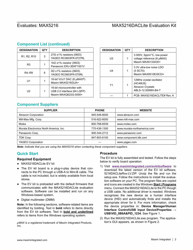
download the latest version of the EV kit software, 5216DACLiteRxx-LV.ZIP. Unzip the file and run thesetup.exe.Followtheinstructionstoinstalltheevalua-tion software on your PC. The program files are copied and icons are created in the Windows Start | Programs menu. Connect the MAX5216DACLite to the PC though aUSBcable.Noadditionaldriverisneeded;Windowsrecognizes the new device as a human interfacedevice (HID) and automatically finds and installs theappropriate driver for it. Formore information, checkthe device properties in: Device Manager\Human Interface Control\USB Input Device\Properties → USB\VID_0B6A&PID_1234.SeeFigure1.
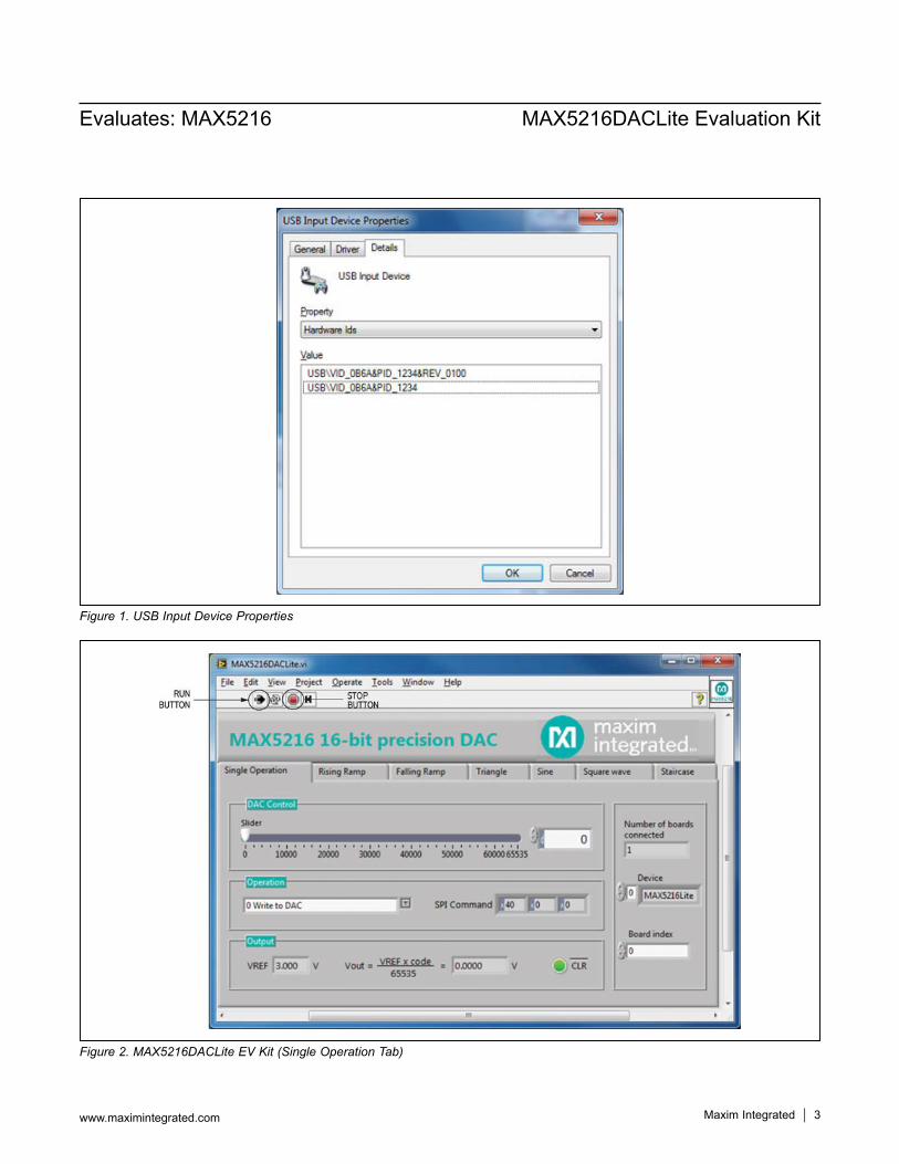
2) RuntheMAX5216DACLite.exeprogram.Theapplica-tion’sGUIappears,asshowninFigure2.
DESIGNATION QTY DESCRIPTION
R1,R2,R10 3 27Ω±1%resistors(0603)YAGEORC0603FR-0727RL
R3 1 1kΩ±1%resistor(0603)PanasonicERJ-3EKF1001V
R4–R9 6 0Ω±1%resistors(0603)YAGEORC0603FR-070RL
U1 1 16-bit VOUTDAC(8µMAX®)Maxim MAX5216GUA+
U2 116-bit microcontroller with USB2.0interface(64LQFP)MaximMAXQ622G-0000+
DESIGNATION QTY DESCRIPTION
U3 13.000V,3ppm/°C,low-powervoltagereference(8µMAX)MaximMAX6133A30+
U4 13.3Vultra-lownoiseLDO (5SC70)MaximMAX8510EXK33+
Y1 1
12MHzcrystaloscillator(HC49US)Abracon Crystals ABLS-12.000MH-B4-T
— 1 PCB:MAX5216DACLITE#Rev.A
SUPPLIER PHONE WEBSITEAbracon Corporation 945-546-8000 www.abracon.com
Mill-Max Mfg. Corp. 516-922-6000 www.mill-max.com
Molex 800-768-6539 www.molex.com
MurataElectronicsNorthAmerica,Inc. 770-436-1300 www.murata-northamerica.com
Panasonic Corp. 800-344-2112 www.panasonic.com
TDK Corp. 847-803-6100 www.component.tdk.com
YAGEOCorporation — www.yageo.com
Maxim Integrated 3
Evaluates: MAX5216 MAX5216DACLite Evaluation Kit
www.maximintegrated.com
Figure 1. USB Input Device Properties
Figure 2. MAX5216DACLite EV Kit (Single Operation Tab)
Maxim Integrated 4
Evaluates: MAX5216 MAX5216DACLite Evaluation Kit
www.maximintegrated.com
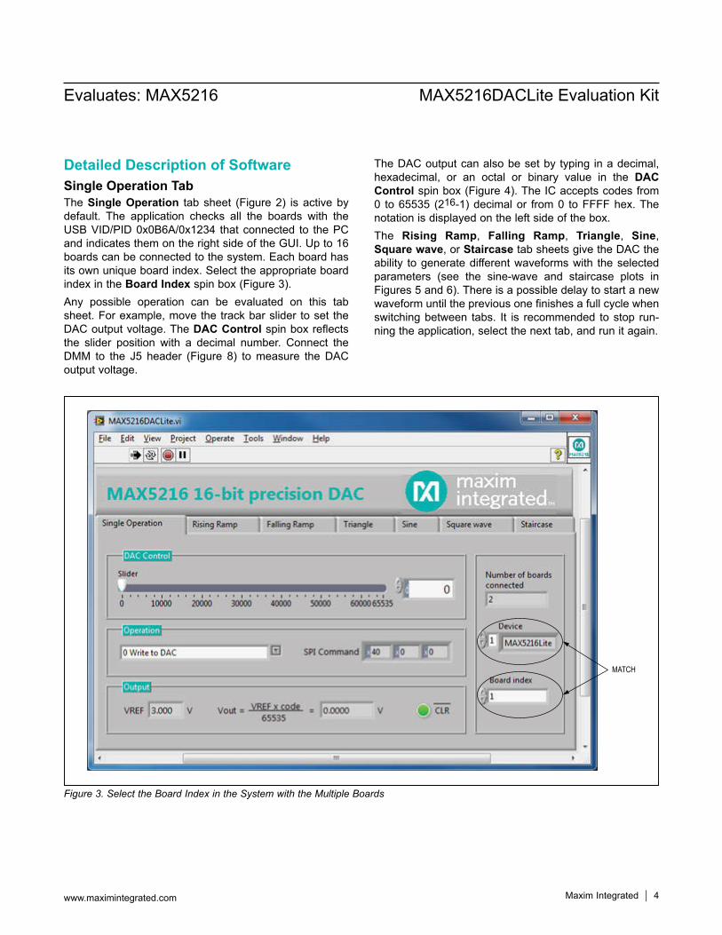
Detailed Description of SoftwareSingle Operation TabThe Single Operation tabsheet (Figure2) isactivebydefault. The application checks all the boards with the USBVID/PID0x0B6A/0x1234 thatconnected to thePCand indicates them on the right side of the GUI. Up to 16 boards can be connected to the system. Each board has its own unique board index. Select the appropriate board index in the Board Indexspinbox(Figure3).Any possible operation can be evaluated on this tab sheet.Forexample,movethetrackbarslider toset theDAC output voltage. The DAC Control spin box reflects the slider position with a decimal number. Connect the DMM to the J5 header (Figure 8) tomeasure theDACoutput voltage.
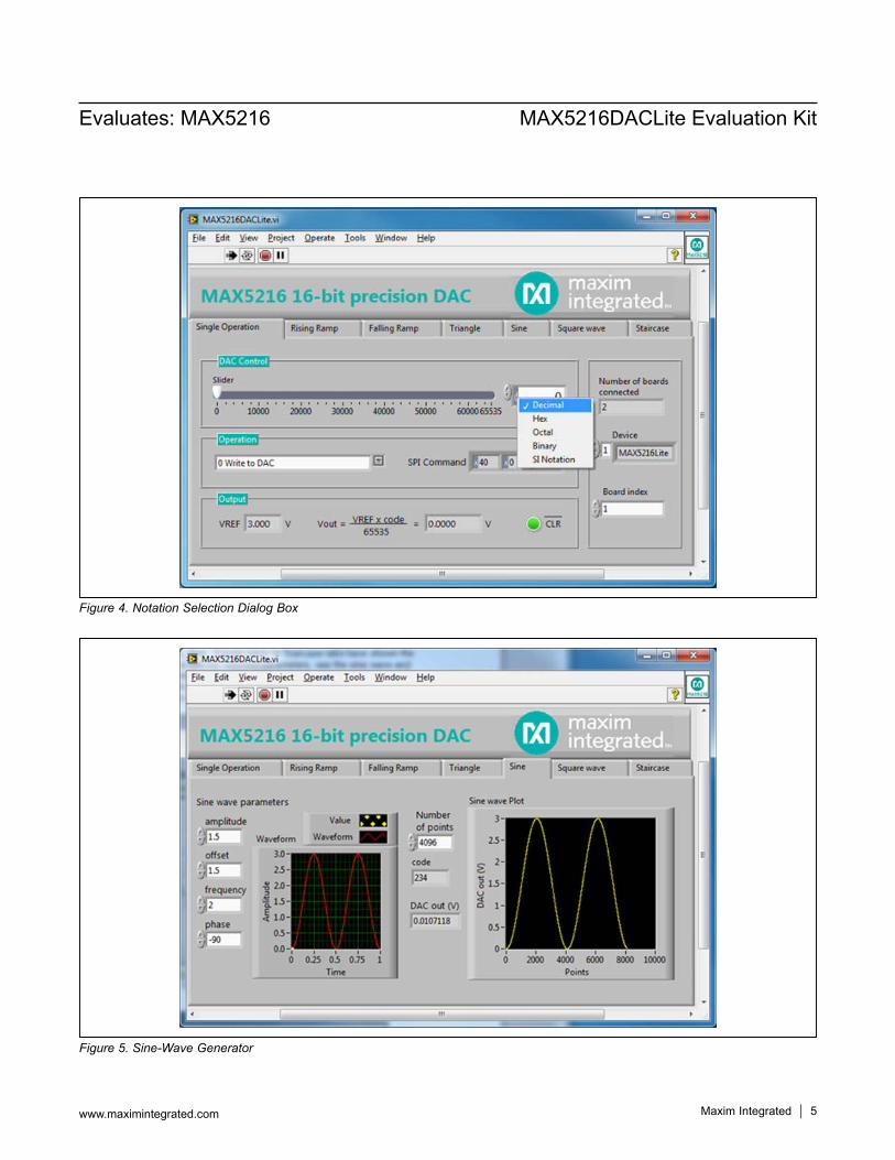
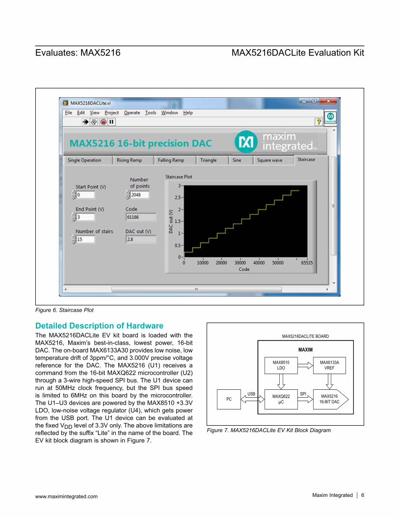
The DAC output can also be set by typing in a decimal, hexadecimal, or an octal or binary value in the DAC Controlspinbox(Figure4).TheICacceptscodesfrom0 to65535 (216-1)decimalor from0 toFFFFhex.Thenotation is displayed on the left side of the box.The Rising Ramp, Falling Ramp, Triangle, Sine, Square wave, or Staircase tab sheets give the DAC the ability to generate different waveforms with the selected parameters (see the sine-wave and staircase plots in Figures5and6).Thereisapossibledelaytostartanewwaveform until the previous one finishes a full cycle when switching between tabs. It is recommended to stop run-ning the application, select the next tab, and run it again.
Figure 3. Select the Board Index in the System with the Multiple Boards
MATCH
Maxim Integrated 5
Evaluates: MAX5216 MAX5216DACLite Evaluation Kit
www.maximintegrated.com
Figure 5. Sine-Wave Generator
Figure 4. Notation Selection Dialog Box
Maxim Integrated 6
Evaluates: MAX5216 MAX5216DACLite Evaluation Kit
www.maximintegrated.com
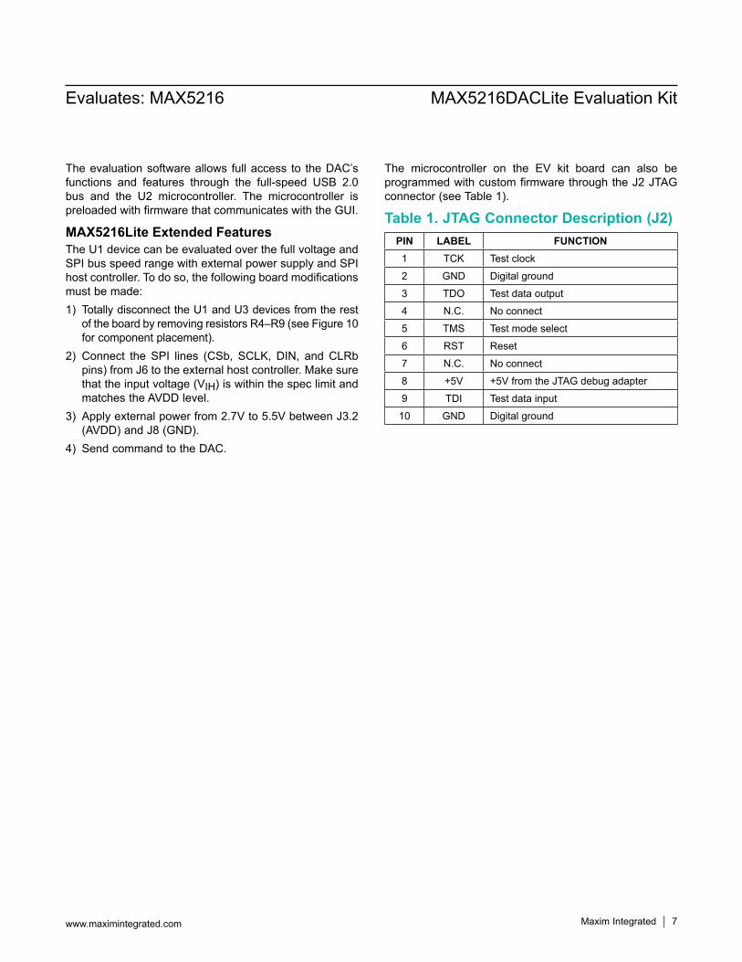
Detailed Description of HardwareThe MAX5216DACLite EV kit board is loaded with the MAX5216, Maxim’s best-in-class, lowest power, 16-bit DAC.Theon-boardMAX6133A30provideslownoise,lowtemperaturedriftof3ppm/°C,and3.000Vprecisevoltagereference for the DAC. The MAX5216 (U1) receives a commandfromthe16-bitMAXQ622microcontroller(U2)through a 3-wire high-speed SPI bus. The U1 device can run at 50MHz clock frequency, but the SPI bus speedis limited to 6MHz on this board by themicrocontroller.TheU1–U3devicesarepoweredbytheMAX8510+3.3VLDO,low-noisevoltageregulator(U4),whichgetspowerfrom theUSBport.TheU1device canbeevaluatedatthe fixed VDD level of 3.3V only. The above limitations are reflected by the suffix “Lite” in the name of the board. The EVkitblockdiagramisshowninFigure7.
Figure 6. Staircase Plot
Figure 7. MAX5216DACLite EV Kit Block Diagram
MAX8510LDO
MAX5216DACLITE BOARD
MAXIM
MAX6133AVREF
MAX521616-BIT DAC
MAXQ622µC
SPIUSBPC
Maxim Integrated 7
Evaluates: MAX5216 MAX5216DACLite Evaluation Kit
www.maximintegrated.com
The evaluation software allows full access to the DAC’s functions and features through the full-speed USB 2.0bus and the U2 microcontroller. The microcontroller is preloaded with firmware that communicates with the GUI.
MAX5216Lite Extended FeaturesThe U1 device can be evaluated over the full voltage and SPI bus speed range with external power supply and SPI host controller. To do so, the following board modifications must be made:1) Totally disconnect the U1 and U3 devices from the rest
oftheboardbyremovingresistorsR4–R9(seeFigure10for component placement).
2) Connect the SPI lines (CSb, SCLK,DIN, andCLRbpins)fromJ6totheexternalhostcontroller.Makesurethat the input voltage (VIH) is within the spec limit and matches the AVDD level.
3) Applyexternalpowerfrom2.7Vto5.5VbetweenJ3.2(AVDD)andJ8(GND).
4) Send command to the DAC.
The microcontroller on the EV kit board can also be programmedwithcustomfirmwarethroughtheJ2JTAGconnector (see Table 1).
Table 1. JTAG Connector Description (J2)PIN LABEL FUNCTION1 TCK Test clock
2 GND Digital ground
3 TDO Test data output
4 N.C. Noconnect
5 TMS Test mode select
6 RST Reset
7 N.C. Noconnect
8 +5V +5VfromtheJTAGdebugadapter
9 TDI Test data input
10 GND Digital ground
Maxim Integrated 8
Evaluates: MAX5216 MAX5216DACLite Evaluation Kit
www.maximintegrated.com
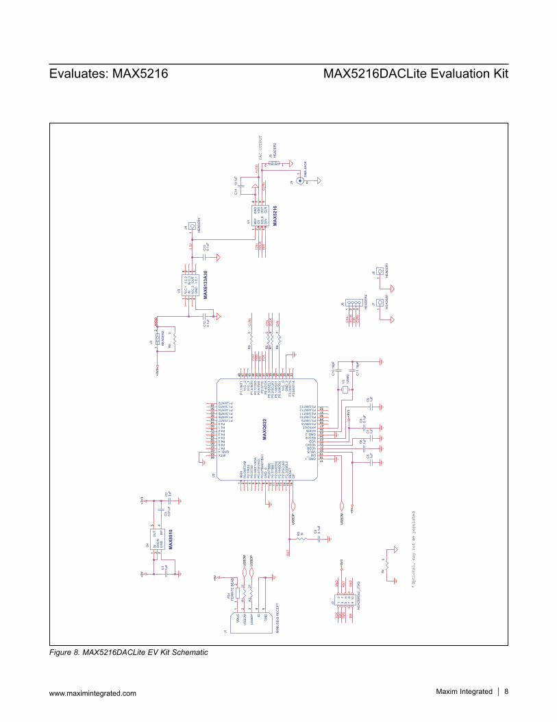
Figure 8. MAX5216DACLite EV Kit Schematic
DAC
OUTP
UT
*Op
tion
al,
may
not
be p
opul
ated
RS
T
TCK
TDO
TMS
TDI
GN
D
RS
T
GN
D
AV
DD
2.5V
AV
DD
CLR
b
CS
bS
CLK
DIN
TDO
TMS
TDI
TCK
CS
bS
CLK
DIN
AV
DD
CS
bS
CLK
DIN C
LRb
CLR
bU
SB
DM
US
BD
P
US
BD
P
US
BD
M
+5V+5
V+3
V3
+3V
3
+5V
+3V
3
+3V
3
R3
1k
U3
MAX6133A30
N.C
.11
IN2
N.C
.23
GN
D4
I.C.1
5O
UT
6N
.C.3
7I.C
.28
Y1
12M
Hz
R2
27
C5
1uF
R1
27
J6
HE
AD
ER
4
1 2 3 4
J2
HE
AD
ER
5x2_
JTA
G
12
34
56
78
910
C4
0.1u
F
R6
0
R8
0
U2
MAXQ622
IRR
X1
P0.
0/IR
TXM
2
P0.
1/R
X0
3
P0.
2/TX
04
P0.
3/R
X1/
SD
A5
P0.
4/TX
1/S
CL
6
P0.
5/TB
A0/
TBA
17
GN
D_0
8
P0.
6/TB
B0
9
P2.
0/M
OS
I011
P0.
7/TB
B1
10
P2.
1/M
ISO
012
P2.
2/S
CLK
013
P2.
3/S
SE
L014
RE
SE
T15
DP
16
GND_117
DM18
VBUS19
VDDB20
VDDIO21
VDD22
REG1823
GND_224
HFXIN25
HFXOUT26
P3.0/INT827
P3.1/INT928
P3.2/INT1029
P3.3/INT1130
P3.4/INT1231
P3.5/INT1332
P3.
6/IN
T14
33P
3.7/
INT1
534
GN
D_3
35N
.C._
036
P5.
0/M
OS
I137
P5.
1/M
ISO
138
P5.
2/S
CLK
139
P5.
3/S
SE
L140
P2.
4/TC
K41
P2.
5/TD
I42
P2.
6/TM
S43
P2.
7/TD
O44
P1.
0/IN
T045
N.C
._1
46N
.C._
247
P1.
1/IN
T148
P1.2/INT249 P1.3/INT350 P1.4/INT451 P1.5/INT552 P1.6/INT653 P1.7/INT754 P4.055 P4.156 P4.257 P4.358 P4.459 P4.560 P4.661 P4.762 GND_463 IRTX64
C3
0.01
uFC
21u
F
J5 HE
AD
ER
2
12
C1
1uF
C12
0.1u
F
R5
0
J3 HE
AD
ER
2
12
C9
1uF
C14
0.1u
F
C13
0.1u
F
J1 MIN
IUS
B-B
-RE
CE
PT
VB
US
1
US
BD
M2
US
BD
P3
ID4
GN
D5
C11
18pF
C10
18pF
J8
HE
AD
ER
1
1
R7
0
C8
0.1u
F
FB1
FER
RIT
E B
EA
D1
2
C7
1uF
C6
1uF
U4
MAX8510
IN1
SH
DN
3
GN
D2
BP
4O
UT
5
J7
HE
AD
ER
1
1
R9
0
J9
SM
A-J
AC
K
1
2
U1
MAX5216
RE
F1
CS
2
SC
LK3
DIN
4C
LR5
OU
T6
VD
D7
GN
D8
R4
0
J4
HE
AD
ER
1
1
Maxim Integrated 9
Evaluates: MAX5216 MAX5216DACLite Evaluation Kit
www.maximintegrated.com
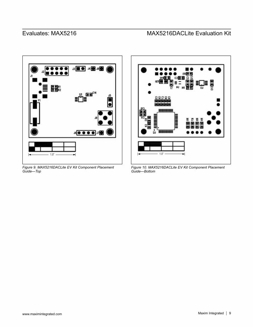
Figure 9. MAX5216DACLite EV Kit Component Placement Guide—Top
Figure 10. MAX5216DACLite EV Kit Component Placement Guide—Bottom
1.0” 1.0”
Maxim Integrated 10
Evaluates: MAX5216 MAX5216DACLite Evaluation Kit
www.maximintegrated.com
#Denotes RoHS compliant.
Ordering InformationPART TYPE
MAX5216DACLITE# EV Kit
Maxim Integrated cannot assume responsibility for use of any circuitry other than circuitry entirely embodied in a Maxim Integrated product. No circuit patent licenses are implied. Maxim Integrated reserves the right to change the circuitry and specifications without notice at any time.
Evaluates: MAX5216 MAX5216DACLite Evaluation Kit
Maxim Integrated and the Maxim Integrated logo are trademarks of Maxim Integrated Products, Inc. © 2012Maxim Integrated Products, Inc. 11
Revision HistoryREVISIONNUMBER
REVISIONDATE DESCRIPTION PAGES
CHANGED0 11/12 Initial release —
For pricing, delivery, and ordering information, please contact Maxim Direct at 1-888-629-4642, or visit Maxim Integrated’s website at www.maximintegrated.com.