Embed Size (px)
Citation preview
NICOTRA SPA - 24040 ZINGONIA (BERGAMO) - Via Modena, 18 - Tel. 035/873111 - Fax 035/884319Website: www.nicotra.it www.nicotra.com E-mail: [email protected]
RDHVENTILATORI CENTRIFUGHIA DOPPIA ASPIRAZIONECON PALE INCLINATE ALL’INDIETRO
DOUBLE INLETCENTRIFUGAL FANSWITH BACKWARDS INCLINED BLADES
DOPPELSEITIG SAUGENDERADIAL-VENTILATORENMIT RÜCKWÄRTS GEKRÜMMTEN SCHAUFELN
VENTILATEURS CENTRIFUGESA DOUBLE OUIEAVEC AUBES INCLINÉES VERS L’ARRIÈRE
VENTILADORES CENTRIFUGOSDE DOBLE ASPIRACIONCON PALAS INCLINADAS HACIA ATRAS
catalogocataloguekatalog
cataloguecatalogo D-3 Marzo 2005
March 2005März 2005Mars 2005Marzo 2005
NICOTRA INDUSTRIALE SPA - 24040 ZINGONIA (BERGAMO) - Via Modena, 18 - Tel. 035/873111 - Fax 035/884319Website: www.nicotra.it E-mail: [email protected]
NICOTRA S.P.A.ZINGONIA (MAIN) FACTORYI - 24040 Zingonia (Bergamo)
Via Modena, 18Tel. 035/873111 - Fax 035/884319Website: www.nicotra.it
www.nicotra.comE-mail: [email protected]
300380 TianjinNum. 10 Fengze Road, Zhangjiawo Industrial AreaXiqing Economic & Development ZoneTel. 8622/87983207 - Fax 8622/87981516
NICOTRA (TIANJIN) FANS & BLOWERS CO. LTD.PRC - E-mail: [email protected]
Campbellfield, Victoria 306147 Jesica RoadTel. 03/93577464 - Fax 03/93578700
NICOTRA AUSTRALIA PTY LTDAUS - E-mail: [email protected]
10150 Bangkok6/29 Soi Suksawadi 2Suksawadi Road, Jomthong,Tel. 662/476 1823-4-5-6 - Fax 662/476 1827
NICOTRA MANUFACTURING (THAI) CO. LTDTH - E-mail: [email protected]
52000 Kuala LumpurLot 33, Jalan 5/32A Kepong Industrial AreaBatu 6 , KepongTel. 03/62573336 - Fax 03/62579337
NICOTRA FANS & BLOWERS MFG SDN BHDMY - E-mail: [email protected]
S 62 6JQ Rotherham - YorkshireUnit D, Parkgate Business ParkTel. 01709/780760 - Fax 01709/780762
NICOTRA UK LTDGB - E-mail: [email protected]
1400 NivellesRue de l' Industrie 4Tel. 067/888140 - Fax 067/216053
NICOTRA BENELUX S.A.B - E-mail: [email protected]
28810 Villalbilla (Madrid)Ctra. Alcala - Villar del Olmo M-204 Km. 2.830Tel. 91/8846110 - Fax 91/8859450
NICOTRA ESPANA S.A.E - E-mail: [email protected]
85551 Kirchheim/MünchenWeissenfelder Str. 2Tel. 089/900692.0 - Fax 089/90069210
NICOTRA G.M.B.H.D - E-mail: [email protected]
69745 Genas-Cedex8 Chemin des Mûriers - Z.I. mi-plaineTel. 0472/790120 - Fax 0472/790121
NICOTRA FRANCE S.A.F - E-mail: [email protected]
33047 Remanzacco (Udine)Strada di Ronchis 5Tel. 0432/668911 - Fax 0432/668408
REMANZACCO FACTORYE-mail: [email protected]
201 301 Noida1-61, Surajpur Ind. AreaSite V, Kasna Greater NoidaTel. 91/120 2580553 - Fax 91/120 2580557
NICOTRA INDIA PRIVATE LIMITEDIND - E-mail: [email protected]
RDHVENTILATORI CENTRIFUGHIA DOPPIA ASPIRAZIONECON PALE INCLINATE ALL’INDIETRO
DOUBLE INLETCENTRIFUGAL FANSWITH BACKWARD INCLINED BLADES
DOPPELSEITIG SAUGENDERADIAL-VENTILATORENMIT RÜCKWÄRTS GEKRÜMMTEN SCHAUFELN
VENTILATEURS CENTRIFUGESA DOUBLE OUIEAVEC AUBES INCLINÉES VERS L’ARRIÈRE
VENTILADORES CENTRIFUGOSDE DOBLE ASPIRACIONCON PALAS INCLINADAS HACIA ATRAS
catalogocataloguekatalogcataloguecatalogo
D-3 03/05
1.640.60 - 2000/2 - 03/05
Nicotra S.p.A. certifica che i ventilatori serie RDH,
versioni L, R, K, K1 e K2, rappresentati in questo
catalogo, sono autorizzati a portare il Marchio
AMCA. Le prestazioni indicate sono basate su
prove e procedure in accordo con il documento
AMCA 211, e soddisfano i requisiti del Programma
AMCA per la Certificazione delle Prestazioni.
Si veda il capitolo a pag. 32 per maggiori dettagli.
Nicotra S.p.A. certifies that RDH fans of the L, R,
K, K1 and K2 versions, shown herein, are licensed
to bear the AMCA Seal. The ratings shown are
based on tests and procedures performed in
accordance with AMCA publication 211 and comply
with the requirements of the AMCA Certified Ratings
Program.
Further details can be found on page 32.
Nicotra S.p.A. bescheinigt, dass die hierin darge-
stellten RDH-Lüfter des Typs L, R, K, K1 und K2
von der AMCA zur Führung ihres Siegels zugelassen
sind. Die dargestellten Einstufungen beruhen auf
Prüfungen und Verfahren, die gemäß AMCA-
Druckschrift 211 durchgeführt wurden und den
Erfordernissen eines von der AMCA zugelassenen
Einstufungsprogramms entsprechen.
Weitere Einzelheiten finden sich auf Seite 32.
Nicotra Spa certifie que les ventilateurs de la série
RDH, versions L, R , K, K1 et K2 présentés dans
ce catalogue sont certifiés AMCA. Les performances
indiquées sont basées sur les essais et procédures
conformément au document AMCA 211 et répondent
aux demandes du Programme AMCA “ Certification
des Performances“ . Pour plus de détails, se reporter
au chapitre de la page 32.
Nicotra S.p.A. certifica que los ventiladores serie
RDH, versiones L, R, K, K1 y K2, representados
en este catálogo, están autorizados para llevar el
Sello AMCA. Las prestaciones indicadas están
basadas en pruebas y procedimientos de acuerdo
con el documento AMCA 211, y satisfacen los
requisitos del Programa AMCA para la Certificación
de las Prestaciones.
Ver el capítulo de la pág. 32.
Marzo 2005March 2005März 2005Mars 2005Marzo 2005
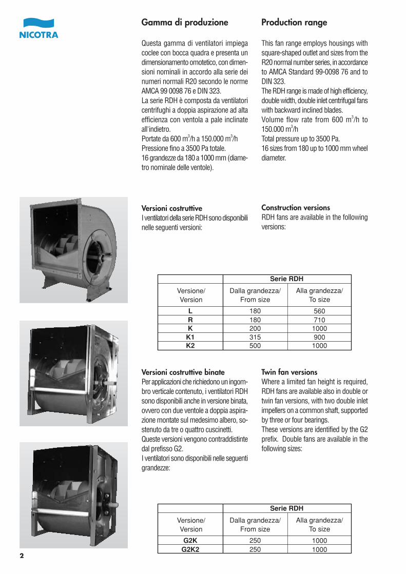
Gamma di produzione
Questa gamma di ventilatori impiegacoclee con bocca quadra e presenta undimensionamento omotetico, con dimen-sioni nominali in accordo alla serie deinumeri normali R20 secondo le normeAMCA 99 0098 76 e DIN 323.La serie RDH è composta da ventilatoricentrifughi a doppia aspirazione ad altaefficienza con ventola a pale inclinateall'indietro.Portate da 600 m3/h a 150.000 m3/hPressione fino a 3500 Pa totale.16 grandezze da 180 a 1000 mm (diame-tro nominale delle ventole).
Versioni costruttiveI ventilatori della serie RDH sono disponibilinelle seguenti versioni:
Production range
This fan range employs housings withsquare-shaped outlet and sizes from theR20 normal number series, in accordanceto AMCA Standard 99-0098 76 and toDIN 323.The RDH range is made of high efficiency,double width, double inlet centrifugal fanswith backward inclined blades.Volume flow rate from 600 m3/h to150.000 m3/hTotal pressure up to 3500 Pa.16 sizes from 180 up to 1000 mm wheeldiameter.
Construction versionsRDH fans are available in the followingversions:
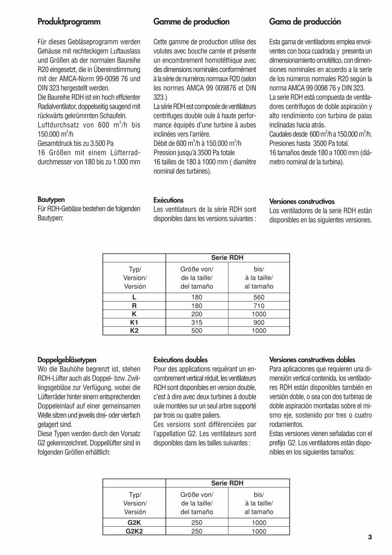
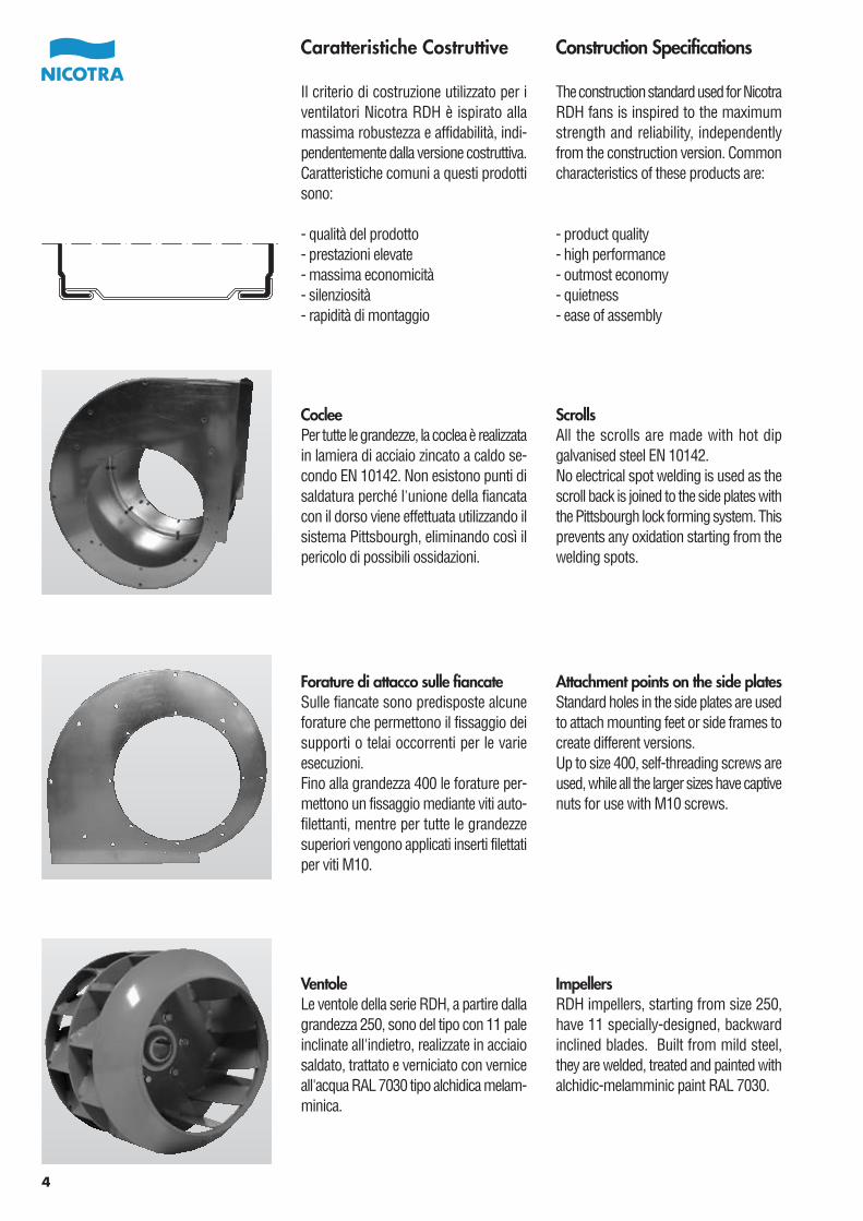
Versioni costruttive binatePer applicazioni che richiedono un ingom-bro verticale contenuto, i ventilatori RDHsono disponibili anche in versione binata,ovvero con due ventole a doppia aspira-zione montate sul medesimo albero, so-stenuto da tre o quattro cuscinetti.Queste versioni vengono contraddistintedal prefisso G2.I ventilatori sono disponibili nelle seguentigrandezze:
Twin fan versionsWhere a limited fan height is required,RDH fans are available also in double ortwin fan versions, with two double inletimpellers on a common shaft, supportedby three or four bearings.These versions are identified by the G2prefix. Double fans are available in thefollowing sizes:
Serie RDH
Versione/Version
Dalla grandezza/From size
Alla grandezza/To size
LRK
K1K2
180180200315500
560710
1000900
1000
Serie RDH
Versione/Version
Dalla grandezza/From size
Alla grandezza/To size
G2KG2K2
250250
10001000
2
3
Serie RDH
Typ/Version/Versión
Größe von/de la taille/del tamaño
bis/à la taille/al tamaño
LRK
K1K2
180180200315500
560710
1000900
1000
Serie RDH
Typ/Version/Versión
Größe von/de la taille/del tamaño
bis/à la taille/al tamaño
G2KG2K2
250250
10001000
Produktprogramm
Für dieses Gebläseprogramm werdenGehäuse mit rechteckigem Luftauslassund Größen ab der normalen BaureiheR20 eingesetzt, die in Übereinstimmungmit der AMCA-Norm 99-0098 76 undDIN 323 hergestellt werden.Die Baureihe RDH ist ein hoch effizienterRadialventilator, doppelseitig saugend mitrückwärts gekrümmten Schaufeln.Luftdurchsatz von 600 m3/h bis150.000 m3/hGesamtdruck bis zu 3.500 Pa16 Größen mit einem Lüfterrad-durchmesser von 180 bis zu 1.000 mm
BautypenFür RDH-Gebläse bestehen die folgendenBautypen:
Gama de producción
Esta gama de ventiladores emplea envol-ventes con boca cuadrada y presenta undimensionamiento omotético, con dimen-siones nominales en acuerdo a la seriede los números normales R20 según lanorma AMCA 99 0098 76 y DIN 323.La serie RDH está compuesta de ventila-dores centrífugos de doble aspiración yalto rendimiento con turbina de palasinclinadas hacia atrás.Caudales desde 600 m3/h a 150.000m3/h.Presiones hasta 3500 Pa total.16 tamaños desde 180 a 1000 mm (diá-metro nominal de la turbina).
Versiones constructivasLos ventiladores de la serie RDH estándisponibles en las siguientes versiones.
DoppelgebläsetypenWo die Bauhöhe begrenzt ist, stehenRDH-Lüfter auch als Doppel- bzw. Zwil-lingsgebläse zur Verfügung, wobei dieLüfterräder hinter einem entsprechendenDoppeleinlauf auf einer gemeinsamenWelle sitzen und jeweils drei- oder vierfachgelagert sind.Diese Typen werden durch den VorsatzG2 gekennzeichnet. Doppellüfter sind infolgenden Größen erhältlich:
Versiones constructivas doblesPara aplicaciones que requieren una di-mensión vertical contenida, los ventilado-res RDH están disponibles también enversión doble, o sea con dos turbinas dedoble aspiración montadas sobre el mi-smo eje, sostenido por tres o cuatrorodamientos.Estas versiones vienen señaladas con elprefijo G2. Los ventiladores están dispo-nibles en los siguientes tamaños:
Gamme de production
Cette gamme de production utilise desvolutes avec bouche carrée et présenteun encombrement homotéthique avecdes dimensions nominales conformémentà la série de numéros normaux R20 (selonles normes AMCA 99 009876 et DIN323.)La série RDH est composée de ventilateurscentrifuges double ouïe à haute perfor-mance équipés d’une turbine à aubesinclinées vers l’arrière.Débit de 600 m3/h à 150.000 m3/hPression jusqu’à 3500 Pa totale16 tailles de 180 à 1000 mm ( diamètrenominal des turbines).
ExécutionsLes ventilateurs de la série RDH sontdisponibles dans les versions suivantes :
Exécutions doublesPour des applications requérant un en-combrement vertical réduit, les ventilateursRDH sont disponibles en version double,c’est à dire avec deux turbines à doubleouïe montées sur un seul arbre supportépar trois ou quatre paliers.Ces versions sont différenciées parl’appellation G2. Les ventilateurs sontdisponibles dans les tailles suivantes :
4
Caratteristiche Costruttive
Il criterio di costruzione utilizzato per iventilatori Nicotra RDH è ispirato allamassima robustezza e affidabilità, indi-pendentemente dalla versione costruttiva.Caratteristiche comuni a questi prodottisono:
- qualità del prodotto- prestazioni elevate- massima economicità- silenziosità- rapidità di montaggio
Construction Specifications
The construction standard used for NicotraRDH fans is inspired to the maximumstrength and reliability, independentlyfrom the construction version. Commoncharacteristics of these products are:
- product quality- high performance- outmost economy- quietness- ease of assembly
Forature di attacco sulle fiancateSulle fiancate sono predisposte alcuneforature che permettono il fissaggio deisupporti o telai occorrenti per le varieesecuzioni.Fino alla grandezza 400 le forature per-mettono un fissaggio mediante viti auto-filettanti, mentre per tutte le grandezzesuperiori vengono applicati inserti filettatiper viti M10.
Attachment points on the side platesStandard holes in the side plates are usedto attach mounting feet or side frames tocreate different versions.Up to size 400, self-threading screws areused, while all the larger sizes have captivenuts for use with M10 screws.
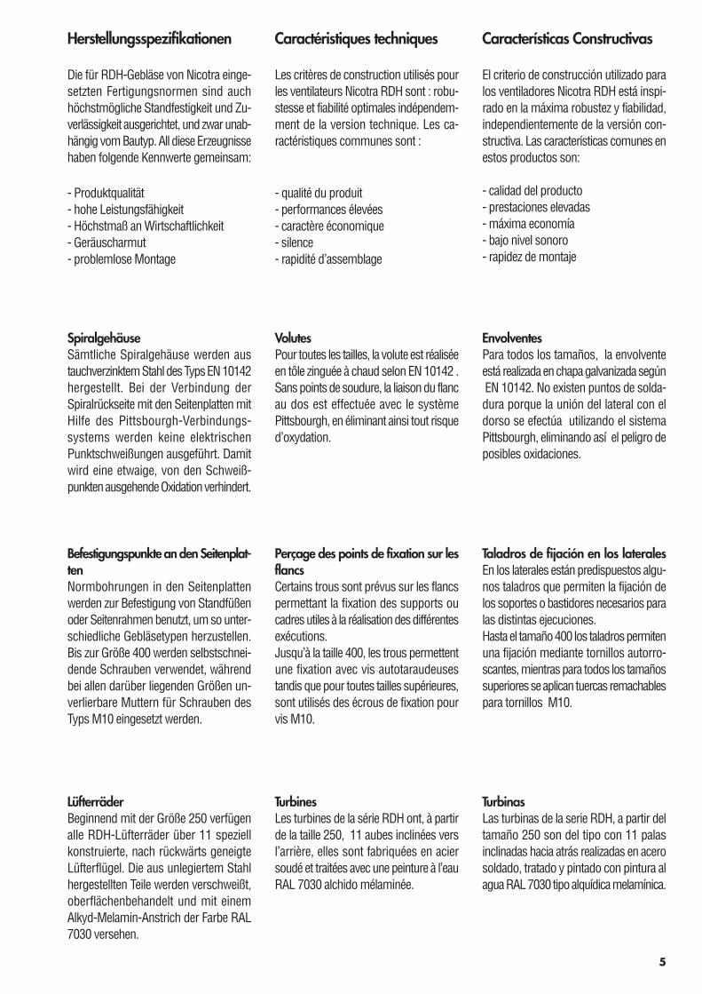
VentoleLe ventole della serie RDH, a partire dallagrandezza 250, sono del tipo con 11 paleinclinate all'indietro, realizzate in acciaiosaldato, trattato e verniciato con verniceall'acqua RAL 7030 tipo alchidica melam-minica.
ImpellersRDH impellers, starting from size 250,have 11 specially-designed, backwardinclined blades. Built from mild steel,they are welded, treated and painted withalchidic-melamminic paint RAL 7030.
CocleePer tutte le grandezze, la coclea è realizzatain lamiera di acciaio zincato a caldo se-condo EN 10142. Non esistono punti disaldatura perché l'unione della fiancatacon il dorso viene effettuata utilizzando ilsistema Pittsbourgh, eliminando così ilpericolo di possibili ossidazioni.
ScrollsAll the scrolls are made with hot dipgalvanised steel EN 10142.No electrical spot welding is used as thescroll back is joined to the side plates withthe Pittsbourgh lock forming system. Thisprevents any oxidation starting from thewelding spots.
5
Herstellungsspezifikationen
Die für RDH-Gebläse von Nicotra einge-setzten Fertigungsnormen sind auchhöchstmögliche Standfestigkeit und Zu-verlässigkeit ausgerichtet, und zwar unab-hängig vom Bautyp. All diese Erzeugnissehaben folgende Kennwerte gemeinsam:
- Produktqualität- hohe Leistungsfähigkeit- Höchstmaß an Wirtschaftlichkeit- Geräuscharmut- problemlose Montage
Características Constructivas
El criterio de construcción utilizado paralos ventiladores Nicotra RDH está inspi-rado en la máxima robustez y fiabilidad,independientemente de la versión con-structiva. Las características comunes enestos productos son:
- calidad del producto- prestaciones elevadas- máxima economía- bajo nivel sonoro- rapidez de montaje
SpiralgehäuseSämtliche Spiralgehäuse werden austauchverzinktem Stahl des Typs EN 10142hergestellt. Bei der Verbindung derSpiralrückseite mit den Seitenplatten mitHilfe des Pittsbourgh-Verbindungs-systems werden keine elektrischenPunktschweißungen ausgeführt. Damitwird eine etwaige, von den Schweiß-punkten ausgehende Oxidation verhindert.
EnvolventesPara todos los tamaños, la envolventeestá realizada en chapa galvanizada según EN 10142. No existen puntos de solda-dura porque la unión del lateral con eldorso se efectúa utilizando el sistemaPittsbourgh, eliminando así el peligro deposibles oxidaciones.
Befestigungspunkte an den Seitenplat-tenNormbohrungen in den Seitenplattenwerden zur Befestigung von Standfüßenoder Seitenrahmen benutzt, um so unter-schiedliche Gebläsetypen herzustellen.Bis zur Größe 400 werden selbstschnei-dende Schrauben verwendet, währendbei allen darüber liegenden Größen un-verlierbare Muttern für Schrauben desTyps M10 eingesetzt werden.
Taladros de fijación en los lateralesEn los laterales están predispuestos algu-nos taladros que permiten la fijación delos soportes o bastidores necesarios paralas distintas ejecuciones.Hasta el tamaño 400 los taladros permitenuna fijación mediante tornillos autorro-scantes, mientras para todos los tamañossuperiores se aplican tuercas remachablespara tornillos M10.
LüfterräderBeginnend mit der Größe 250 verfügenalle RDH-Lüfterräder über 11 speziellkonstruierte, nach rückwärts geneigteLüfterflügel. Die aus unlegiertem Stahlhergestellten Teile werden verschweißt,oberflächenbehandelt und mit einemAlkyd-Melamin-Anstrich der Farbe RAL7030 versehen.
TurbinasLas turbinas de la serie RDH, a partir deltamaño 250 son del tipo con 11 palasinclinadas hacia atrás realizadas en acerosoldado, tratado y pintado con pintura alagua RAL 7030 tipo alquídica melamínica.
Caractéristiques techniques
Les critères de construction utilisés pourles ventilateurs Nicotra RDH sont : robu-stesse et fiabilité optimales indépendem-ment de la version technique. Les ca-ractéristiques communes sont :
- qualité du produit- performances élevées- caractère économique- silence- rapidité d’assemblage
VolutesPour toutes les tailles, la volute est réaliséeen tôle zinguée à chaud selon EN 10142 .Sans points de soudure, la liaison du flancau dos est effectuée avec le systèmePittsbourgh, en éliminant ainsi tout risqued’oxydation.
Perçage des points de fixation sur lesflancsCertains trous sont prévus sur les flancspermettant la fixation des supports oucadres utiles à la réalisation des différentesexécutions.Jusqu’à la taille 400, les trous permettentune fixation avec vis autotaraudeusestandis que pour toutes tailles supérieures,sont utilisés des écrous de fixation pourvis M10.
TurbinesLes turbines de la série RDH ont, à partirde la taille 250, 11 aubes inclinées versl’arrière, elles sont fabriquées en aciersoudé et traitées avec une peinture à l’eauRAL 7030 alchido mélaminée.
6
TelaiI telai laterali delle versioni R sono realizzaticon angolari in acciaio zincato Sendzimirsecondo EN 10142.I telai delle versioni rinforzate K, K1, K2,G2K e G2K2 sono costruiti con profilatilaminati a caldo, trattati e protetti convernice all'acqua RAL 7030 tipo alchidicamelamminica. Su richiesta questi telaipossono essere finiti con zincatura a caldo.
Side framesLight-construction side frames of the Rversions are made with cold-formed,galvanised steel “Sendzimir” type EN10142. Heavy-duty side frames of the K,K1, K2, G2K and G2K2 versions are madewith hot-rolled steel sections, welded andcoated with alchidic-melamminic paintRAL 7030. As an option, they can beprotected with hot dip galvanising.
AlberiLavorati a partire da barre rettificate diacciaio al carbonio, utilizzando un proces-so automatico per l'esecuzione delle cavecentrali (chiuse) e d’estremità (aperte).Tutti gli alberi vengono protetti, ad assem-blaggio ultimato, con verniciatura anticor-rosiva di colore giallo brillante. Alberi inacciaio inox possono essere forniti surichiesta, con una opportuna riduzionedella velocità massima raggiungibile. Idiametri degli alberi sono scelti in mododa avere una velocità critica superiore allamassima velocità di funzionamento di unfattore di sicurezza ≥ 1.25
ShaftsManufactured from precision ground,C45 carbon steel bars, using precisiontools to cut keyways.All the shafts are coated, after assembly,with a clearly distinguishable, bright yellowprotective paint.Stainless steel shafts can be provided onrequest, with an appropriate reduction ofthe maximum operating speed.Shaft diameters are selected to achievea safety factor for critical speed ≥ 1.25higher than the maximum operating spe-ed.
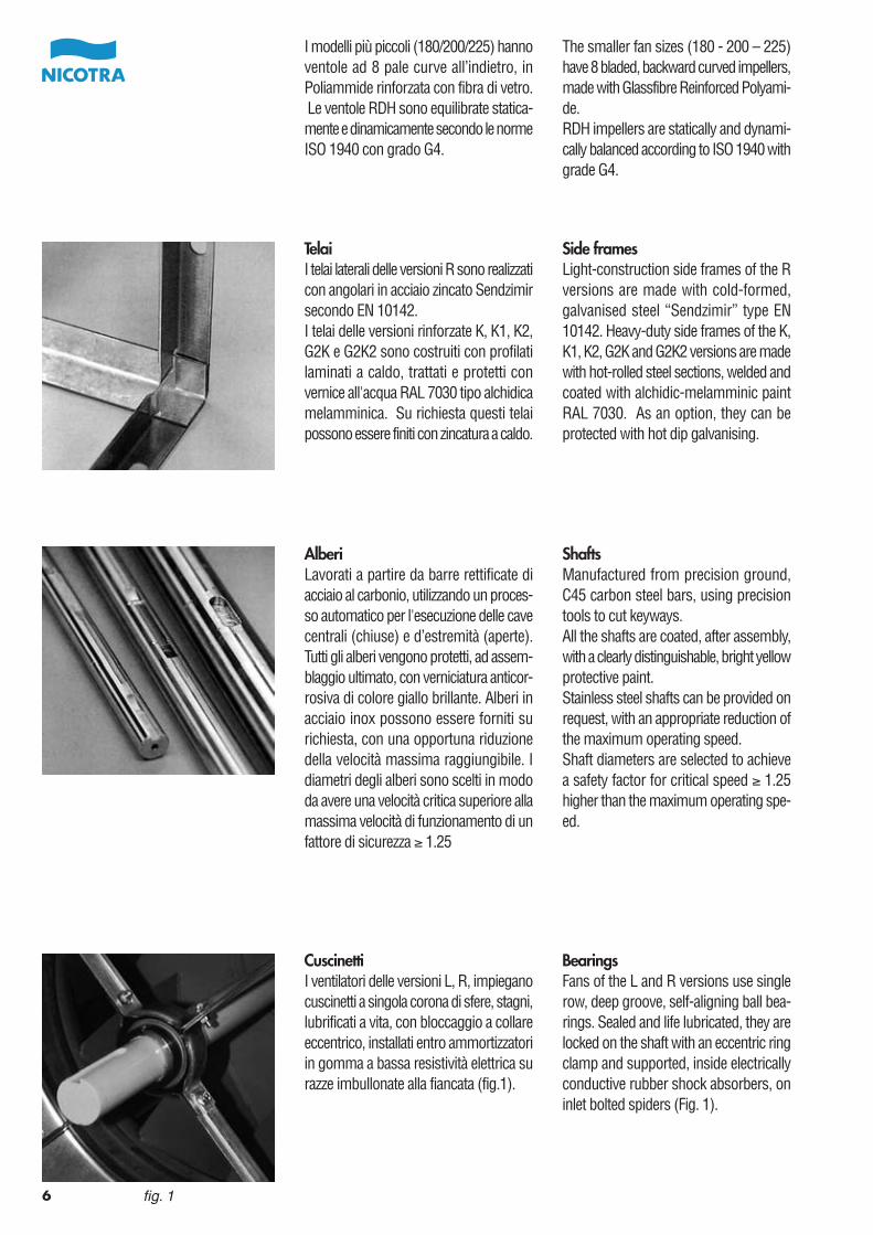
CuscinettiI ventilatori delle versioni L, R, impieganocuscinetti a singola corona di sfere, stagni,lubrificati a vita, con bloccaggio a collareeccentrico, installati entro ammortizzatoriin gomma a bassa resistività elettrica surazze imbullonate alla fiancata (fig.1).
BearingsFans of the L and R versions use singlerow, deep groove, self-aligning ball bea-rings. Sealed and life lubricated, they arelocked on the shaft with an eccentric ringclamp and supported, inside electricallyconductive rubber shock absorbers, oninlet bolted spiders (Fig. 1).
fig. 1
I modelli più piccoli (180/200/225) hannoventole ad 8 pale curve all’indietro, inPoliammide rinforzata con fibra di vetro. Le ventole RDH sono equilibrate statica-mente e dinamicamente secondo le normeISO 1940 con grado G4.
The smaller fan sizes (180 - 200 – 225)have 8 bladed, backward curved impellers,made with Glassfibre Reinforced Polyami-de.RDH impellers are statically and dynami-cally balanced according to ISO 1940 withgrade G4.
7
WellenWerden aus präzisionsgeschliffenem, auf-gekohltem Stabstahl C45 hergestellt, wobeiKeilnuten mit Präzisionswerkzeugen einge-bracht werden.Sämtliche Wellen werden nach der Montagemit einer gut sichtbaren Schutzschichtversehen.Auf Anforderung sind auch Edelstahlwellenverfügbar, wobei sich dann allerdings eineentsprechende Verringerung der höchstmö-glichen Betriebsdrehzahl ergibt. Wellendur-chmesser werden so gewählt, dass sich fürdie kritische Drehzahl ein Sicherheitsfaktorvon ≥1,25 im Vergleich zur höchstzulässigenBetriebsdrehzahl ergibt.
BastidoresLos bastidores laterales de las versionesR están realizados con ángulo de chapagalvanizada Sendzimir según EN 10142.Los bastidores de las versiones reforzadasK, K1, K2, G2K y G2K2 están construidoscon perfiles laminados en caliente, tratadosy protegidos con pintura al agua RAL7030 tipo alquídica melamínica. Bajopedido estos bastidores pueden ser aca-bados con cincado en caliente.
SeitenrahmenDie Leichtbau-Seitenrahmen der R-Typenwerden aus kalt gewalztem, galvanisiertemSendzimir-Stahl des Typs EN 10142 her-gestellt.Hochleistungsrahmen für die Typen K,K1, K2, G2K und G2K2 werden aus warmgewalztem Stahlprofilen hergestellt, dieverschweißt und mit einem Anstrich ausAlkyd-Melamin der Farbe RAL 7030 ver-sehen. Als Sonderzubehör sind feuerver-zinkte Profile erhältlich.
EjesElaborados a partir de barra rectificadade acero al carbono, utilizando un procesoautomático para la ejecución de los cha-veteros centrales (cerrados) y de lasextremidades (abiertos). Todos los ejesestán protegidos después del montaje,con pintura anticorrosiva de color amarillobrillante. Ejes en acero inoxidable puedenser suministrados bajo pedido, con unaoportuna reducción de la velocidad máxi-ma alcanzable. Los diámetros de los ejesestán seleccionados en modo de teneruna velocidad crítica superior a la máximavelocidad de funcionamiento con un factorde seguridad ≥ 1.25
Die kleineren Gebläsegrößen (180 – 200– 225) verfügen jeweils über Lüfterrädermit 8 nach rückwärts geneigten Blätteraus Glasfaser verstärktem Polyamid.Die statische und dynamische Auswuch-tung von RDH-Lüfterrädern erfolgt nachMaßgabe von ISO 1940 für die EinstufungG4.
Los modelos mas pequeños(180/200/225) tienen turbinas a 8 palascurvadas hacia atrás, en Poliamida refor-zada con fibra de vidrio. Las turbinas RDHestán equilibradas estática y dinámica-mente según las normas ISO 1940 congrado G4.
RodamientosLos ventiladores de las versiones L, R,emplean rodamientos de simple coronade esferas, estancos, lubricados de porvida, con bloqueo mediante anillo excén-trico, instalados dentro de amortiguadoresde goma de baja resistencia eléctricasobre brazos remachados al lateral (fig.1).
LagerFür Lüfter der Typen L und R werden jeweilseinreihige Rillen-Pendelkugellager einge-setzt. Nach ihrer Versiegelung im Anschlussan die Lebensdauerschmierung werdensie auf der Welle mit einem Exzenterringfestgeklemmt; sie laufen im Innern vonelektrisch leitfähigen Gummimetalllagernin Läufersternen, die am Einlauf ange-schraubt sind (Abb. 1).
Les plus petites tailles (180 /200/225) ontdes turbines à 8 aubes inclinées versl’arrière, exécution polyamide renforcéfibre de verre. Les turbines RDH sontéquilibrées statiquement et dyna-miquement selon les normes ISO 1940– degré d’équilibrage G4.
CadresLes cadres latéraux de la version R sontréalisés en acier zingué Sendzimir selonEN 10142.Les cadres des versions renforcées K,K1, K2, G2K et G2K2 sont réalisés avecdes profilés laminés à chaud, traités avecune peinture à l’eau RAL 7030 alchidomélaminée. Ces cadres peuvent être surdemande revêtus avec une finition zingageà chaud.
ArbresIls sont réalisés à partir de barres d’acierrectifié au carbone en utilisant un procédéde fabrication automatique pourl’exécution des sièges de clavettes soitau centre (fermées) soit latérales (ouver-tes). Tous les arbres sont protégés parune peinture anti corrosion de couleurjaune brillante.Des arbres en acier inox peuvent êtrefournis sur demande avec une réductionde la vitesse maximum admissible.Les diamètres des arbres sont choisisde façon à obtenir une vitesse critiquesupérieure à la vitesse maximum defonctionnement : facteur de sécurité≥ 1.25
PaliersLes ventilateurs versions L, R sont équipésde roulements à billes, hermétiques, grais-sés à vie avec serrage par bague excen-trique. Ils sont montés sur amortisseursen caoutchouc à faible résistance électri-que sur des croisillons boulonnés auxflancs (fig.1).
8
fig. 2
fig. 3
fig. 4
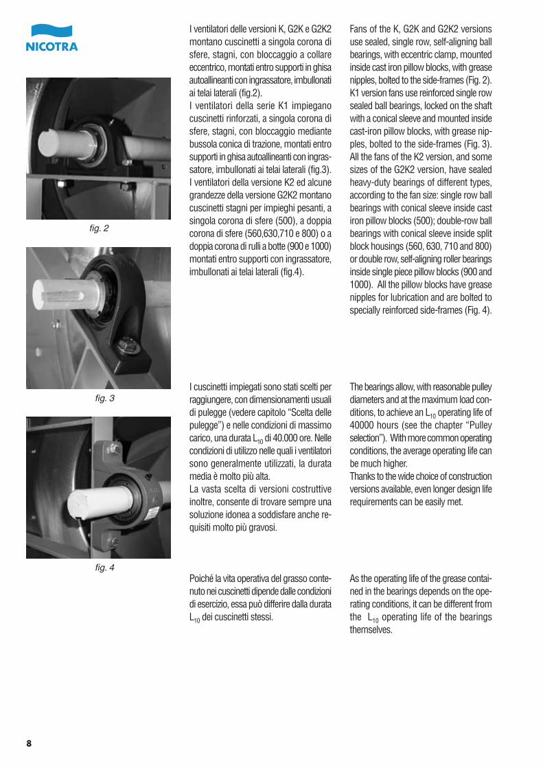
I ventilatori delle versioni K, G2K e G2K2montano cuscinetti a singola corona disfere, stagni, con bloccaggio a collareeccentrico, montati entro supporti in ghisaautoallineanti con ingrassatore, imbullonatiai telai laterali (fig.2).I ventilatori della serie K1 impieganocuscinetti rinforzati, a singola corona disfere, stagni, con bloccaggio mediantebussola conica di trazione, montati entrosupporti in ghisa autoallineanti con ingras-satore, imbullonati ai telai laterali (fig.3).I ventilatori della versione K2 ed alcunegrandezze della versione G2K2 montanocuscinetti stagni per impieghi pesanti, asingola corona di sfere (500), a doppiacorona di sfere (560,630,710 e 800) o adoppia corona di rulli a botte (900 e 1000)montati entro supporti con ingrassatore,imbullonati ai telai laterali (fig.4).
I cuscinetti impiegati sono stati scelti perraggiungere, con dimensionamenti usualidi pulegge (vedere capitolo “Scelta dellepulegge”) e nelle condizioni di massimocarico, una durata L10 di 40.000 ore. Nellecondizioni di utilizzo nelle quali i ventilatorisono generalmente utilizzati, la duratamedia è molto più alta.La vasta scelta di versioni costruttiveinoltre, consente di trovare sempre unasoluzione idonea a soddisfare anche re-quisiti molto più gravosi.
Poiché la vita operativa del grasso conte-nuto nei cuscinetti dipende dalle condizionidi esercizio, essa può differire dalla durataL10 dei cuscinetti stessi.
Fans of the K, G2K and G2K2 versionsuse sealed, single row, self-aligning ballbearings, with eccentric clamp, mountedinside cast iron pillow blocks, with greasenipples, bolted to the side-frames (Fig. 2).K1 version fans use reinforced single rowsealed ball bearings, locked on the shaftwith a conical sleeve and mounted insidecast-iron pillow blocks, with grease nip-ples, bolted to the side-frames (Fig. 3).All the fans of the K2 version, and somesizes of the G2K2 version, have sealedheavy-duty bearings of different types,according to the fan size: single row ballbearings with conical sleeve inside castiron pillow blocks (500); double-row ballbearings with conical sleeve inside splitblock housings (560, 630, 710 and 800)or double row, self-aligning roller bearingsinside single piece pillow blocks (900 and1000). All the pillow blocks have greasenipples for lubrication and are bolted tospecially reinforced side-frames (Fig. 4).
The bearings allow, with reasonable pulleydiameters and at the maximum load con-ditions, to achieve an L10 operating life of40000 hours (see the chapter “Pulleyselection”). With more common operatingconditions, the average operating life canbe much higher.Thanks to the wide choice of constructionversions available, even longer design liferequirements can be easily met.
As the operating life of the grease contai-ned in the bearings depends on the ope-rating conditions, it can be different fromthe L10 operating life of the bearingsthemselves.
9
Für die Gebläse des Typs K, G2K und G2K2werden versiegelte, einreihige Pendelkugel-lager eingesetzt, die mit Exzenterklemmenbefestigt werden und innerhalb von Guss-stehlagern mit Schmiernippeln laufen, diejeweils am Seitenrahmen befestigt sind(Abb. 2).Für Gebläse des Typs K1 werden verstärkte,einreihige und versiegelte Lager eingesetzt,die jeweils mit einem Konus auf der Wellebefestigt werden und innerhalb von Guss-stehlagern mit Schmiernippeln laufen, welchejeweils am Seitenrahmen verschraubt sind(Abb. 3). Sämtliche Gebläse des Typs K2sowie einige Versionen des Typs G2K2verfügen über versiegelte Hochleistungslagerunterschiedlicher Typen, die sich jeweilsnach der Gebläsegröße richten: einreihigeKugellager mit Konus in Gussstehlagern(500); zweireihige Kugellager mit Konus inmehrteiligen Stehlagern (560, 630, 710 und800) oder zweireihige Pendelkugellager ineinteiligen Stehlagern (900 und 1000).Sämtliche Stehlager verfügen über Schmier-nippel zum Nachfetten und werden an spe-ziell verstärkten Teilen des Seitenrahmensverschraubt (Abb. 4).
Die Lager ermöglichen bei geeignetemDurchmesser der Riemenscheibe und unterHöchstlastbedingungen eine BetriebsdauerL10 von 40.000 Stunden (siehe Abschnitt“Auswahl der Riemenscheibe”). Untergängigeren Betriebsbedingungen liegt dieLebensdauer für den Gebläsebetrieb unterUmständen sehr viel höher.Dank der breiten Auswahl an verfügbarenBautypen lassen sich auch noch höhereAnforderungen an die Lebensdauer derjeweiligen Anlage ohne weiteres erfüllen.
Da die Lebensdauer des Schmiermittels inden Lagern unter anderem auch von denBetriebsbedingungen abhängt, kann es sichvon der Lebensdauer L10 der Lager selbstunterscheiden.
Los ventiladores de las versiones K, G2Ky G2K2 montan rodamientos de simplecorona de esferas, estancos, con bloqueomediante anillo excéntrico, montados ensoportes de fundición autoalineantes conengrasador, atornillados a los bastidoreslaterales (fig.2).Los ventiladores de la serie K1 empleanrodamientos reforzados, a simple coronade esferas, estancos, con bloqueo me-diante guía cónica de tracción, montadosen soportes de fundición autoalineantescon engrasador, atornillados a los basti-dores laterales (fig.3).Los ventiladores de la serie K2 y algunostamaños de la versión G2K2 montanrodamientos estancos para empleos pe-sados, a simple corona de esferas (500),a doble corona de esferas (560, 630, 710y 800) o a doble corona de rodillos abom-bados (900 y 1000) montados en sopor-tes con engrasador, atornillados a losbastidores laterales (fig.4).
Los rodamientos utilizados has sido se-leccionados para conseguir, con dimen-sionamientos usuales de poleas (ver elcapítulo “Selección de las poleas”) y enlas condiciones de carga máxima, unaduración L10 de 40.000 horas. En lascondiciones de empleo en la que losventiladores son generalmente utilizados,la duración media es mucho mas alta.La vasta selección de versiones construc-tivas permite además encontrar siempreuna solución idónea para satisfacer tam-bién requisitos mas gravosos.
Como la vida operativa de la grasa conte-nida en los rodamientos depende de lascondiciones de ejercicio, la misma puedediferir de la duración L10 de los rodamien-tos.
Les ventilateurs des versions K, G2K etG2K2 sont équipés de roulements à billes,hermétiques avec serrage par bagueexcentrique. Ils sont montés sur supportsen fonte avec graisseur, boulonnés auxcadres latéraux (fig. 2).Les ventilateurs de la série K1 sont équipésde paliers renforcés, à billes, hermétiquesavec serrage par manchon conique detraction. Ils sont montés sur supports enfonte auto alignés avec graisseur et bou-lonnés sur les cadres latéraux (fig 3).Les ventilateurs de la série K2 et quelquestailles de la version G2K2 sont équipésde roulements hermétiques pour desutilisations lourdes à simple couronne debilles (500), à double couronne de billes(560, 630, 710 et 800) ou à double cou-ronne de paliers à rouleaux (900 et 1000)montés sur supports avec graisseur,boulonnés aux cadres latéraux (fig 4).
Les roulements utilisés ont été choisispour atteindre, avec des dimension-nements habituels des poulies (voir cha-pitre “ choix des poulies ”) et avec desconditions de charge maximum, pourune durée de vie L10 de 40.000 heures.Les conditions d’utilisation des ventilateurspermettent une durée moyenne beau-coup plus élevée.De plus, le vaste panel de versions tech-niques permet toujours de trouver unesolution adéquate afin de répondre auxdemandes les plus contraignantes.
Puisque la durée de vie de la graissecontenue dans les roulements dépenddes conditions d’utilisation, elle peut êtredifférente de la durée L10 des roulementseux-mêmes.
10
VerniciatureSu richiesta, possono essere realizzateversioni interamente verniciate con vernicea polvere o all'acqua di vario spessore.
PaintingsSpecial powder-paint coatings of variousthickness can be supplied on request.
Esecuzioni antideflagrantiSu richiesta, possono essere realizzateversioni a sicurezza aumentata, con boc-cagli di aspirazione in lega di alluminio,lega di rame o con bordo riportato inrame.Si prega di contattare il fabbricante per lascelta ed i dettagli.
Ignition protected versionsIgnition protected versions can be builton request, with inlet cones made ofaluminium, copper or with copper rubbingstripes on the edge of the inlet cones.Please, contact the manufacturer forselection and details.
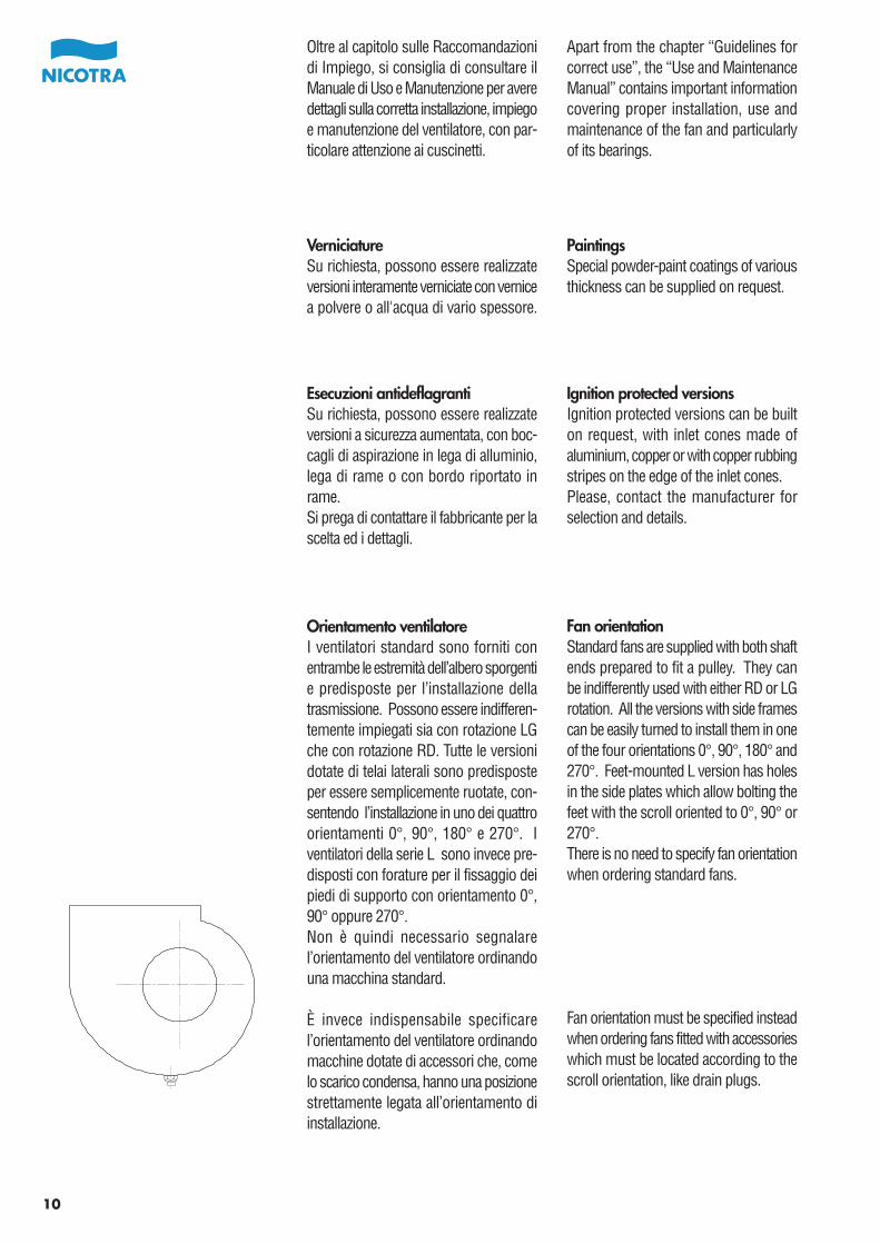
Orientamento ventilatoreI ventilatori standard sono forniti conentrambe le estremità dell’albero sporgentie predisposte per l’installazione dellatrasmissione. Possono essere indifferen-temente impiegati sia con rotazione LGche con rotazione RD. Tutte le versionidotate di telai laterali sono predisposteper essere semplicemente ruotate, con-sentendo l’installazione in uno dei quattroorientamenti 0°, 90°, 180° e 270°. Iventilatori della serie L sono invece pre-disposti con forature per il fissaggio deipiedi di supporto con orientamento 0°,90° oppure 270°.Non è quindi necessario segnalarel’orientamento del ventilatore ordinandouna macchina standard.
È invece indispensabile specificarel’orientamento del ventilatore ordinandomacchine dotate di accessori che, comelo scarico condensa, hanno una posizionestrettamente legata all’orientamento diinstallazione.
Fan orientationStandard fans are supplied with both shaftends prepared to fit a pulley. They canbe indifferently used with either RD or LGrotation. All the versions with side framescan be easily turned to install them in oneof the four orientations 0°, 90°, 180° and270°. Feet-mounted L version has holesin the side plates which allow bolting thefeet with the scroll oriented to 0°, 90° or270°.There is no need to specify fan orientationwhen ordering standard fans.
Fan orientation must be specified insteadwhen ordering fans fitted with accessorieswhich must be located according to thescroll orientation, like drain plugs.
Oltre al capitolo sulle Raccomandazionidi Impiego, si consiglia di consultare ilManuale di Uso e Manutenzione per averedettagli sulla corretta installazione, impiegoe manutenzione del ventilatore, con par-ticolare attenzione ai cuscinetti.
Apart from the chapter “Guidelines forcorrect use”, the “Use and MaintenanceManual” contains important informationcovering proper installation, use andmaintenance of the fan and particularlyof its bearings.
11
AnstrichSpezielle Pulverlackierungen unterschied-licher Schichtdicke sind auf Anforderungverfügbar.
PinturasBajo pedido, pueden ser realizadas ver-siones enteramente pintadas con pinturaal polvo o al agua de varios espesores.
BrandschutztypenAuf Anforderung sind auch Brandgeschützte Typen lieferbar, bei denen derEinlasskegel aus Alu oder Kupfer bzw.Abriebstreifen an den Kanten der Füh-rungskegel aus Kupfer bestehen.Setzen Sie sich bitte mit dem Herstellerbezüglich Gebläsewahl und sonstigerEinzelheiten in Verbindung.
Ejecuciones antideflagrantesBajo pedido, pueden realizarse versionescon seguridad aumentada, con oído deaspiración en aleación aluminio, en alea-ción cobre, o con borde superpuesto encobre.Se ruega contactar con el fabricante parala selección y los detalles.
GebläseausrichtungStandardmäßige Gebläse werden mitWellen geliefert, die an beiden Enden eineRiemenscheibe aufnehmen können. Sielassen sich somit sowohl in rechter alsauch linker Drehrichtung betreiben. Sämtli-che Typen mit Seitenrahmen lassen sichproblemlos so drehen, dass sie sich ineiner der vier vorgesehenen Ausrichtun-gen befinden: 0°, 90°, 180° und 270°.Der fußmontierte L-Typ verfügt überBohrungen in den Seitenplatten, die eineVerschraubung der Füße mit dem Spiral-anschluss in den Stellungen 0°, 90° bzw.270° erlauben.Bei der Bestellung von Standardgebläsenerübrigt sich die Angabe der Gebläseaus-richtung.
Die Gebläseausrichtung muss allerdingsbei der Bestellung von Gebläsen angege-ben werden, die mit Zubehörteilen ausge-stattet sind, die entsprechend der Drehrich-tung des Spiralgehäuses auszurichtensind, so etwa Ablassschrauben.
Orientación del ventiladorLos ventiladores estándar se suministrancon las dos extremidades del eje salientesy predispuestos para la instalación de latransmisión. Pueden ser utilizados indi-stintamente con rotación LG o con rota-ción RD. Todas las versiones dotadas debastidores laterales están predispuestaspara ser giradas simplemente, consintien-do la instalación en una de las cuatroorientaciónes 0°, 90°, 180° y 270° . Losventiladores de la serie L están predispue-stos con taladros para la fijación de lospies de soporte con orientaciónes 0°, 90°o 270°. No es por lo tanto necesarioindicar la orientación del ventilador enpedidos de máquinas estándar.
Es sin embargo indispensable especificarla orientación del ventilador en pedidosde máquinas dotadas de accesorios que,como el purgador de condensados, tienenuna posición extrechamente ligada a laorientación del ventilador.
PeintureSur demande, nous pouvons réaliser desversions entièrement revêtues avec pein-ture poudre ou à l’eau dans différentesépaisseurs.
Exécutions antidéflagrantesSur demande, nous pouvons réaliser desversions à sécurité augmentée avec desouïes d’aspiration en alliage d’aluminium,alliage de cuivre ou à bord rapporté encuivre.Veuillez nous contacter pour plus dedétails.
Orientation du ventilateurLes ventilateurs standards sont fournisavec les deux extrémités de l’arbre sor-tantes et prêtes pour l’installation de latransmission. Ils peuvent être employésindifféremment en rotation LG ou rotationRD. Toutes les versions équipées decadres latéraux sont prêtes pour êtresimplement positionnées dans l’une desquatre orientations 0°, 90°, 180° et 270°.Les ventilateurs de la série L sont enrevanche prévus avec des perçages pourla fixation des pieds supports avec uneorientation 0°, 90° ou 270°.Il n’est donc pas nécessaire de préciserl’orientation du ventilateur lors de la com-mande d’un appareil standard.
Il est au contraire indispensable de spéci-fier l’orientation du ventilateur lors de lacommande d’appareils équipésd’accessoires, comme la purge de volute,dont la position est liée à l’orientationd’installation.
Neben dem Abschnitt “Richtlinien für denordnungsgemäßen Einsatz” finden sich imBedienungs- und Wartungshandbuch wei-tere wichtige Angaben über ordnungs-gemäßen Einbau, sachgerechte Nutzungund Wartung des Gebläses und insbeson-dere seiner Lager.
En plus du chapitre sur les recommanda-tions d’utilisation, nous conseillons deconsulter le “ Manuel d’utilisation et deMaintenance ” afin d’obtenir plus de détailssur une installation correcte et sur lamaintenance du ventilateur et particulière-ment celle des roulements.
Además del capítulo Recomendacionesde Empleo, se aconseja consultar el Ma-nual de Uso y Mantenimiento para tenerdetalles sobre la correcta instalación,empleo y mantenimiento del ventilador,con particular atención a los rodamientos.
When requested, fan orientation is iden-tified, according to ISO 13349 and Euro-vent 1/1, when looking at the fan fromthe drive side. RD means right (clockwise)rotation, while LG means left (counter-clockwise) rotation.The achievable orientations are shown inthe drawing below.
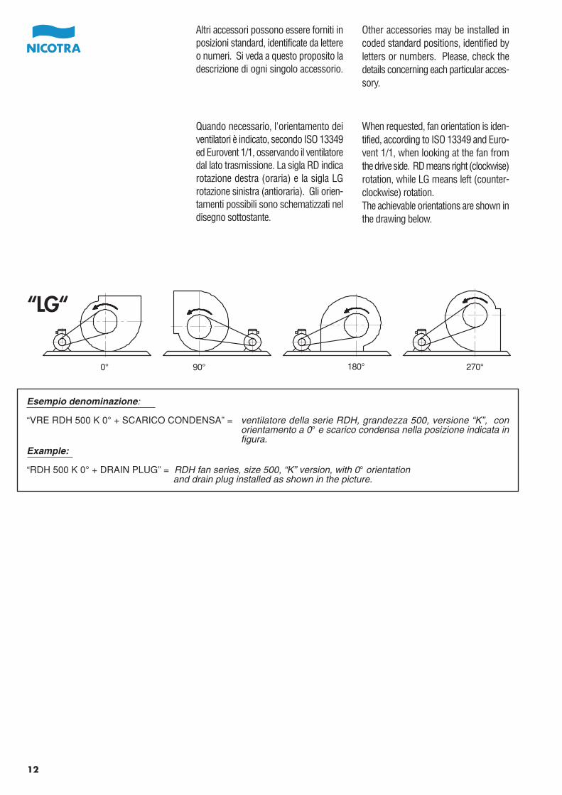
Quando necessario, l'orientamento deiventilatori è indicato, secondo ISO 13349ed Eurovent 1/1, osservando il ventilatoredal lato trasmissione. La sigla RD indicarotazione destra (oraria) e la sigla LGrotazione sinistra (antioraria). Gli orien-tamenti possibili sono schematizzati neldisegno sottostante.
12
“LG“
0° 90° 180° 270°
Esempio denominazione:
“VRE RDH 500 K 0° + SCARICO CONDENSA” = ventilatore della serie RDH, grandezza 500, versione “K”, conorientamento a 0° e scarico condensa nella posizione indicata infigura.
Example:
“RDH 500 K 0° + DRAIN PLUG” = RDH fan series, size 500, “K” version, with 0° orientation and drain plug installed as shown in the picture.
Other accessories may be installed incoded standard positions, identified byletters or numbers. Please, check thedetails concerning each particular acces-sory.
Altri accessori possono essere forniti inposizioni standard, identificate da lettereo numeri. Si veda a questo proposito ladescrizione di ogni singolo accessorio.
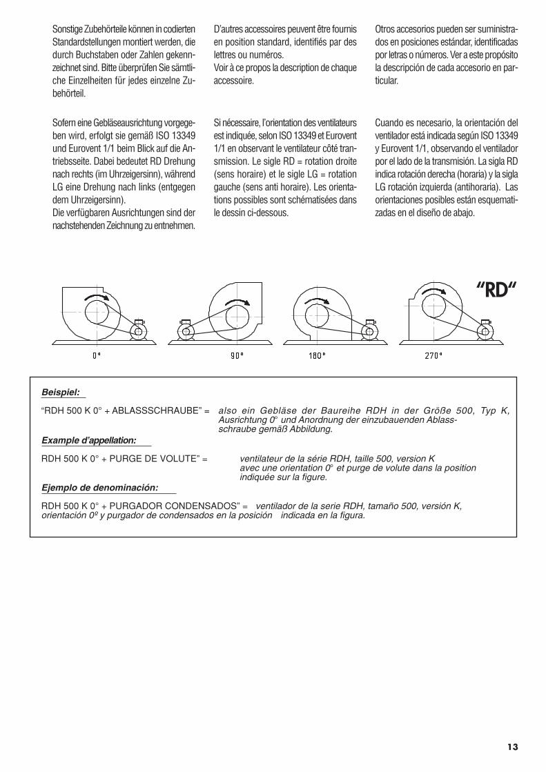
“RD“
Cuando es necesario, la orientación delventilador está indicada según ISO 13349y Eurovent 1/1, observando el ventiladorpor el lado de la transmisión. La sigla RDindica rotación derecha (horaria) y la siglaLG rotación izquierda (antihoraria). Lasorientaciones posibles están esquemati-zadas en el diseño de abajo.
13
Sofern eine Gebläseausrichtung vorgege-ben wird, erfolgt sie gemäß ISO 13349und Eurovent 1/1 beim Blick auf die An-triebsseite. Dabei bedeutet RD Drehungnach rechts (im Uhrzeigersinn), währendLG eine Drehung nach links (entgegendem Uhrzeigersinn).Die verfügbaren Ausrichtungen sind dernachstehenden Zeichnung zu entnehmen.
Beispiel:
“RDH 500 K 0° + ABLASSSCHRAUBE” = also ein Gebläse der Baureihe RDH in der Größe 500, Typ K,Ausrichtung 0° und Anordnung der einzubauenden Ablass-schraube gemäß Abbildung.
Example d’appellation:
RDH 500 K 0° + PURGE DE VOLUTE” = ventilateur de la série RDH, taille 500, version K avec une orientation 0° et purge de volute dans la position
indiquée sur la figure.Ejemplo de denominación:
RDH 500 K 0° + PURGADOR CONDENSADOS” = ventilador de la serie RDH, tamaño 500, versión K, orientación 0º y purgador de condensados en la posición indicada en la figura.
Si nécessaire, l’orientation des ventilateursest indiquée, selon ISO 13349 et Eurovent1/1 en observant le ventilateur côté tran-smission. Le sigle RD = rotation droite(sens horaire) et le sigle LG = rotationgauche (sens anti horaire). Les orienta-tions possibles sont schématisées dansle dessin ci-dessous.
Otros accesorios pueden ser suministra-dos en posiciones estándar, identificadaspor letras o números. Ver a este propósitola descripción de cada accesorio en par-ticular.
Sonstige Zubehörteile können in codiertenStandardstellungen montiert werden, diedurch Buchstaben oder Zahlen gekenn-zeichnet sind. Bitte überprüfen Sie sämtli-che Einzelheiten für jedes einzelne Zu-behörteil.
D’autres accessoires peuvent être fournisen position standard, identifiés par deslettres ou numéros.Voir à ce propos la description de chaqueaccessoire.
PerformanceSpecifications
Air performanceAir performance ratings of the fans de-scribed by this catalogue have been deri-ved from performance tests made withinstallation type “B”, with free inlet andducted outlet. These tests were carriedout in the Nicotra laboratory, in accordancewith the following standards: AMCA 210-99 (Fig. 12), UNI 10531 (Fig. 30 c andpar. 29.2 f) and ISO 5801 (Fig. 69 c andpar. 30.2 f).Ratings are referred to the standard airdensity of 1.20 kg/m3.Dynamic pressure and outlet air velocity,as shown on the scales below each dia-gram, are calculated in accordance withthe said standards, using the total outletarea for calculations.
Caratteristiche di funzionamento
Prestazioni aeraulicheLe prestazioni dei ventilatori indicate sulpresente catalogo, sono riferite al funzio-namento in installazione “B”, con aspira-zione libera e bocca di mandata canalizzata.Tali prestazioni sono state calcolate apartire da prove svolte presso il laboratorioNicotra, in accordo con le norme AMCA210-99 (fig. 12), UNI 10531 (fig. 30 c epar. 29.2 f) ed ISO 5801 (fig. 69 c e par.30.2 f). Le prestazioni sono riferite ad unadensità standard dell’aria di 1.20 kg/m3.Le scale della pressione dinamica con-venzionale e della velocità d'uscita dell'aria,tracciate sotto ciascun diagramma, sonocalcolate secondo norme, facendo riferi-mento all’area totale della bocca di man-data.
14
“Free-outlet” operationWhen operating in installation type “A”,with free inlet and free outlet, the availablestatic pressure of the fan, pSA, is lowerthan when the fan is used with ductedoutlet, and can be satisfactorily calculatedsubtracting, from the total pressure in thecatalogue, an increased dynamic pressure,calculated by multiplying conventionaldynamic pressure by a factor Kd shownbelow.
This dynamic pressure increase represen-ts the effect of the airflow contractionproduced by the cut-off plate and theabsence of an outlet duct, which wouldact as a diffuser, allowing at least partialconversion of the excess of dynamicpressure into static pressure.Fan performance so calculated is notAMCA Licensed.
Funzionamento “a bocca libera”Nel funzionamento in installazione “A”,con aspirazione e bocca di mandata noncanalizzate, la pressione statica utile delventilatore, pSA , è più bassa che nel fun-zionamento con bocca canalizzata, e puòessere calcolata, con buona approssima-zione, sottraendo, alla pressione totale dicatalogo, una pressione dinamica mag-giorata, ottenuta moltiplicando la pressionedinamica normalizzata per il fattore Kd
indicato nella tabella sotto riportata.
dell’incremento della pressione dinamica,provocato dallo strozzamento del flussoad opera del deflettore, e della mancanzadi un canale di mandata, che opererebbecome diffusore, permettendo di riconver-tire la pressione dinamica eccedente inpressione statica.Le prestazioni così calcolate non sonocertificate AMCA.
Kd - RDH
1.74
15
Características defuncionamiento
Prestaciones aerólicasLas prestaciones de los ventiladores indi-cadas en el presente catálogo, estánreferidas al funcionamiento en instalación“B”, con aspiración libre y boca de impul-sión canalizada. Tales prestaciones hansido calculadas a partir de pruebas efec-tuadas en el laboratorio Nicotra, de acuer-do con la norma AMCA 210-99 (fig. 12),UNI 10531 (fig. 30 c y par. 29.2 f) y ISO5801 (fig. 69 c y par. 30.2 f).Las prestaciones están referidas a unadensidad estándar del aire de 1.20 kg/m3.Las escalas de la presión dinámica con-vencional y de la velocidad de salida delaire, trazadas bajo cada diagrama, estáncalculadas según normas, haciendo refe-rencia al área total de la boca de impulsión.
Leistungsspezifikationen
LuftdurchsatzDie Luftdurchsatzwerte für die in diesemKatalog bezeichneten Gebläse wurdenjeweils anhand von Leistungsprüfungenmit einer Anlage vom Typ “B” ermittelt,welche über einen Zulauf ohne und einenAblauf mit Luftführung verfügt. DiesePrüfungen wurden im Firmenlabor beiNicotra ausgeführt, und zwar nach Maß-gabe der folgenden Normen: AMCA 210-99 (Abb. 12), UNI 10531 (Abb. 30 c undUnterabs. 29.2 f) sowie ISO 5801 (Abb.69 c und Unterabs. 30.2 f).Alle Werte beziehen sich auf die Normluft-dichte von 1,20 kg/m3.Staudruck und Abluftgeschwindigkeitwerden gemäß den Maßstäben unter deneinzelnen Diagrammen in Übereinstim-mung mit den genannten Normen ermit-telt, wobei die gesamte Auslassfläche fürdie Berechnungen herangezogen wird.
Kd - RDH
1.74
Funcionamiento ”a boca libre”En el funcionamiento en instalación “A”,con aspiración y boca de impulsión nocanalizada, la presión estática útil delventilador, pSA , es mas baja que en elfuncionamiento con boca canalizada, ypuede ser calculada, con una buena apro-ximación, restando a la presión total delcatálogo, una presión dinámica superior,obtenida multiplicando la presión dinámicanormalizada por el factor Kd indicado enla tabla representada abajo.
Este aumento representa el efecto delincremento de la presión dinámica, pro-vocado por el estrangulamiento del flujoa causa del deflector, y de la falta de unconducto de impulsión, que haría la fun-ción de difusor, permitiendo de reconvertirla presión dinámica excedente en presiónestática.Las prestaciones así calculadas no estáncertificadas AMCA.
Betrieb ohne Luftführung am AuslassWenn eine Anlage des Typs “A” gefahrenwird, d.h. ohne Luftführung am Ein- undAuslass, liegt der verfügbare statischeDruck pSA des Gebläses unter dem Wertfür den Betrieb mit Luftführung am Aus-lass; die Berechnung lässt sich problemlosdurch Subtraktion des entsprechend an-gehobenen Staudrucks vom Ge-samtdruckwert laut Katalog ermitteln,wobei die Erhöhung durch Multiplizierungdes üblichen Staudrucks um den bei-stehend dargestellten Faktor Kd erfolgt.
Der Anstieg des Staudrucks entspricht denAuswirkungen der Strömungsverengungdurch den Sperrschieber und den Auslassohne Luftführung, der als Diffusor wirkenwürde, sodass zumindest eine Teilumwand-lung des überschüssigen Staudrucks instatischen Druck stattfinden könnte. Fürdie Messung von Gebläseleistungen nachdiesem Verfahren liegt keine AMCA-Lizenzvor.
Caractéristiques defonctionnement
Performances aérauliquesLes performances des ventilateurs pré-sentés dans ce catalogue font référenceau fonctionnement en utilisation “ B ”avec aspiration libre et bouche canalisée.Ces performances ont été calculées àpartir d’essais réalisés dans le laboratoireNicotra conformément aux normes AMCA210-99 (fig.12), UNI 10531 (fig.30 c etpar. 29.2 f) et ISO 5801 (fig.69 c et par.30.2 f).Les performances se réfèrent à une den-sité standard de l’air de 1.20 kg/m3. Leséchelles de la pression dynamique con-ventionnelle et de la vitesse de sortie d’air,tracées sous chaque diagramme sontcalculées suivant des normes et en faisantréférence à la surface totale de la bouchede refoulement.
Fonctionnement “ bouche bée ”Dans le fonctionnement en utilisation “A”avec aspiration et bouche de refoulementnon canalisée, la pression statique utiledu ventilateur, pSA, est plus basse qu’encas de fonctionnement en bouche cana-lisée; elle peut être calculée, avec unebonne approximation, en soustrayant dela pression totale du catalogue une pres-sion dynamique obtenue en multipliantla pression dynamique normalisée par lefacteur kd du tableau ci-dessous.
Cette augmentation représente l’effet del’accroissement de la pression dynamiqueprovoqué par la contraction du flux causépar le déflecteur et par l’absence de gaineau refoulement qui opèrerait commediffuseur en permettant de reconvertir lapression dynamique excédentaire en pres-sion statique.Les performances ainsi calculées ne sontpas certifiées AMCA.
16
Fan powerPower curves shown on fan performancediagrams are impeller absorbed power,Wr . Vertical scales to the right of eachdiagram show the power consumptionof the fan bearings for each fan ver-sion, Wb.Fan shaft power, Wa, is given by the addi-tion of impeller power and power usedby the bearings.In most cases, bearing power is smalland often negligible when compared toimpeller power, but becomes relativelymore important with decreasing fan sizeand speed, and may be significant at thelower end of the size range.Drive losses are not calculated.Fan mechanical input power is a functionof flow rate and speed, but doesn’t changebetween installation types A (with freeinlet and free outlet) and B (with free inletand ducted outlet).
Potenza assorbitaLe curve di potenza assorbita, tracciatenei diagrammi di funzionamento, rappre-sentano la potenza assorbita dalla ventola,Wr . Le scale verticali tracciate a destradei diagrammi rappresentano inoltre, perciascuna versione costruttiva, la potenzadissipata per attrito nei cuscinetti, Wb.La potenza totale all’albero del ventilatore,Wa , è data dalla somma dei due valori.Nella grande maggioranza dei casi, ilcontributo di potenza assorbita dovuto aicuscinetti è piccolo e spesso trascurabile,ma cresce al diminuire del diametro edella velocità del ventilatore e può diventarerilevante nel caso delle grandezze piùpiccole. La potenza dissipata nell’eventualetrasmissione non viene considerata.La potenza assorbita dal ventilatore dipen-de dalla portata e dal numero di giri, manon cambia tra il funzionamento a man-data libera (installazione A) e a mandatacanalizzata (installazione B).
EfficiencyEfficiency values shown on the diagramsare total impeller efficiency, with the fanoperating with installation type B ( rB
according to ISO 5801 symbols), withoutconsidering bearing power losses, drivelosses and, of course, motor power losses.Impeller efficiency actually is, for a givenfan size, a function also of fan speed or,alternatively, of the Reynolds number Re.Experimental measurements have shown,anyway, that within the fan speed rangeshown in the catalogue, the actual effi-ciency variation of RDH impellers is wellwithin the allowed tolerances. Conse-quently, this small change was not repre-sented in the catalogue to keep it simpler.
EfficienzaI valori di efficienza tracciati nei diagrammirappresentano l’efficienza totale dellaventola, in installazione B ( rB secondo lasimbologia della norma ISO 5801), alnetto degli attriti nei cuscinetti e, ovvia-mente, nella trasmissione e nel motore.L’efficienza della ventola, per una datagrandezza di ventilatore, dipende, a rigore,anche dalla velocità di rotazione, ovverodal numero di Reynolds Re.Da prove sperimentali si è tuttavia rilevatoche, nell’ambito delle velocità di impiegorappresentate a catalogo, la variazionereale di efficienza delle ventole RDH èampiamente entro la tolleranza concessae, per semplicità, si è quindi preferito nonrappresentare questa piccola variazione.
Potencia absorbidaLas curvas de potencia absorbida, trazadasen los diagramas de funcionamiento,representan la potencia absorbida por laturbina, Wr. Las escalas verticales trazadasa la derecha de los diagramas representan,para cada versión constructiva, la potenciadisipada por fricción en los rodamien-tos, Wb.La potencia total al eje del ventilador, Wa,será la suma de los dos valores.En la gran mayoría de los casos, la con-tribución de potencia absorbida debida alos rodamientos es pequeña y frecuente-mente despreciable, pero crece al dismi-nuir del diámetro y de la velocidad delventilador y puede llegar a ser relevanteen el caso de los tamaños más pequeños.La potencia disipada en las eventualestransmisiones no está considerada.La potencia absorbida por el ventiladordepende del caudal y del número derevoluciones, pero no cambia entre elfuncionamiento a boca libre (instalación A)y a impulsión canalizada (instalación B).
17
GebläseleistungDie Leistungskurven auf den Gebläsedia-grammen entsprechen der vom Lüfterradaufgenommenen Leistung Wr . Dersenkrechte Maßstab rechts vom jeweiligenDiagramm zeigt die Leistungsaufnahmeder Gebläselager Wb für die einzelnenBautypen.Die Wellenleistung Wa des Gebläses ergibtsich aus der Addition der Lüfterradleistungund der Leistungsaufnahme durch dieLager. In den meisten Fällen liegt dieLeistungsaufnahme der Lager niedrig undkann im Vergleich mit der Lüfter-radleistung vernachlässigt werden; mitabnehmender Gebläsegröße und -Geschwindigkeit nimmt die Bedeutungdieses Wertes zu und kann sich am jeweilsunteren Ende des Größenbereiches alssignifikant erweisen. Antriebsverlustewerden nicht berücksichtigt. Die mecha-nische Eingangsleistung des Gebläses istFunktion von Volumendurchsatz undStrömungsgeschwindigkeit; sie bleibtjedoch unabhängig davon gleich, ob eineAnlage vom Typ A (Ein- und Auslass ohneLuftführung) oder B (Einlauf ohne undAuslass mit Luftführung) gefahren wird.
RendimientoLos valores de rendimiento trazados enlos diagramas representan el rendimientototal de la turbina, en instalación B ( rB
según la simbología de la norma ISO5801) libre de las fricciones en los roda-mientos y, obviamente, en la transmisióny en el motor.El rendimiento de la turbina, para undeterminado tamaño de ventilador, de-pende, con rigor, también de la velocidadde rotación, o bien del número de Rey-nolds Re.De las pruebas experimentales se haadvertido sin embargo que, en el ámbitode la velocidad de trabajo representadaen el catálogo, las variaciones de rendi-miento de la turbina RDH está amplia-mente dentro de la tolerancia concedida y,
WirkungsgradDie Werte für den Wirkungsgrad, die ausden Diagrammen ersichtlich sind, ent-sprechen dem Gesamtwert für dasLüfterrad, wobei das Gebläse an einerAnlage des Typs B betrieben wird ( rB
gemäß den Symbolen laut ISO 5801),wobei die Verlustleistung der Lager desAntriebs und insbesondere des Motorsaußer Betracht bleiben.Der Wirkungsgrad des Laufrades ist füreine bestimmte Gebläsegröße auch eineFunktion der Gebläsedrehzahl bzw. derReynolds-Zahl Re.Durch Messungen ließ sich experimentellohnehin nachweisen, dass im Rahmender im Katalog aufgeführten Drehzahlenfür das Gebläseprogramm die tatsächlicheWirkungsgradabweichung der RDH-
Puissance absorbéeLes courbes de puissance tracées sur lesdiagrammes de fonctionnement repré-sentent la puissance absorbée de la turbineWr. Les graduations verticales tracées àdroite des courbes représentent aussipour chaque version, la puissance dissipéepar frottement dans les roulements Wb.La puissance totale à l’arbre du ventilateur,Wa, est donnée par la somme des deuxvaleurs. Dans la plupart des cas, la con-tribution de la puissance absorbée dueaux roulements est faible et souvent né-gligeable mais augmente lorsque lediamètre et la vitesse du ventilateur dimi-nuent et peut devenir conséquente dansle cas des tailles plus petites.La puissance dissipée par la transmissionéventuelle n’est pas prise en compte.La puissance absorbée du ventilateurdépend du débit et du nombre de toursmais ne change pas entre le fonctionne-ment “bouche bée” (installation A) et celuicanalisé (installation B).
RendementLes valeurs de rendement tracées dansles diagrammes représentent le rende-ment total de la turbine en installation B( rb selon symbolique de la norme ISO5801), nette des frottements dans lesroulements, dans la transmission et dansle moteur.Le rendement de la turbine, pour une taillede ventilateur donnée, dépend aussi dela vitesse de rotation ou du nombre deReynolds Re. D’après des essais expéri-mentaux, on a toutefois relevé que, dansles limites des vitesses d’utilisation repré-sentées au catalogue, la variation réellede rendement des turbines RDH est en-tièrement le fait de la tolérance autoriséeet pour simplifier, on a donc préféré nepas représenter cette petite variation.
18
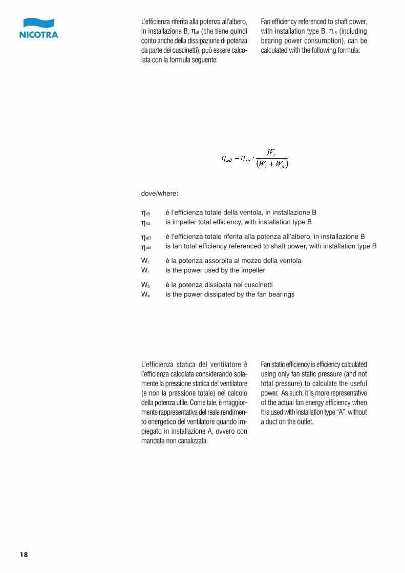
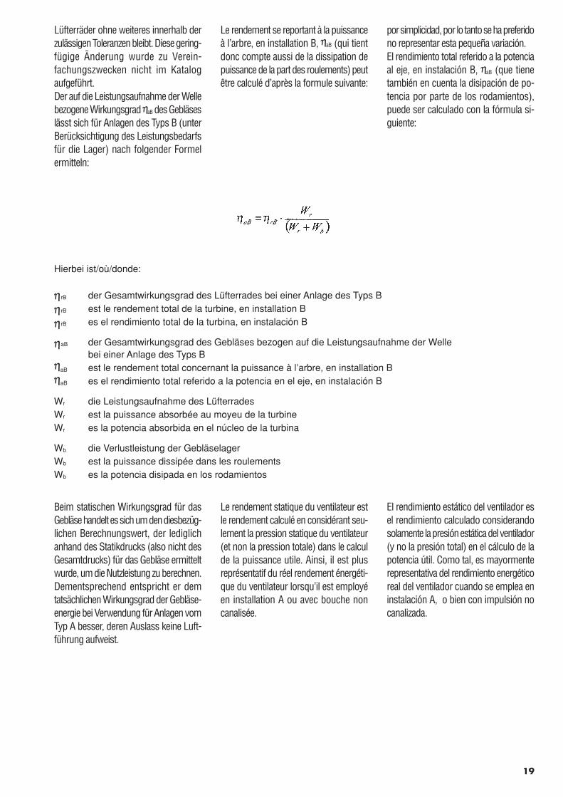
Fan efficiency referenced to shaft power,with installation type B, aB (includingbearing power consumption), can becalculated with the following formula:
L’efficienza riferita alla potenza all’albero,in installazione B, aB (che tiene quindiconto anche della dissipazione di potenzada parte dei cuscinetti), può essere calco-lata con la formula seguente:
Fan static efficiency is efficiency calculatedusing only fan static pressure (and nottotal pressure) to calculate the usefulpower. As such, it is more representativeof the actual fan energy efficiency whenit is used with installation type “A”, withouta duct on the outlet.
L’efficienza statica del ventilatore èl’efficienza calcolata considerando sola-mente la pressione statica del ventilatore(e non la pressione totale) nel calcolodella potenza utile. Come tale, è maggior-mente rappresentativa del reale rendimen-to energetico del ventilatore quando im-piegato in installazione A, ovvero conmandata non canalizzata.
dove/where:
rB è l’efficienza totale della ventola, in installazione B
rB is impeller total efficiency, with installation type B
aB è l’efficienza totale riferita alla potenza all’albero, in installazione B
aB is fan total efficiency referenced to shaft power, with installation type B
Wr è la potenza assorbita al mozzo della ventolaWr is the power used by the impeller
Wb è la potenza dissipata nei cuscinettiWb is the power dissipated by the fan bearings
19
por simplicidad, por lo tanto se ha preferidono representar esta pequeña variación.El rendimiento total referido a la potenciaal eje, en instalación B, aB (que tienetambién en cuenta la disipación de po-tencia por parte de los rodamientos),puede ser calculado con la fórmula si-guiente:
Lüfterräder ohne weiteres innerhalb derzulässigen Toleranzen bleibt. Diese gering-fügige Änderung wurde zu Verein-fachungszwecken nicht im Katalogaufgeführt.Der auf die Leistungsaufnahme der Wellebezogene Wirkungsgrad aB des Gebläseslässt sich für Anlagen des Typs B (unterBerücksichtigung des Leistungsbedarfsfür die Lager) nach folgender Formelermitteln:
El rendimiento estático del ventilador esel rendimiento calculado considerandosolamente la presión estática del ventilador(y no la presión total) en el cálculo de lapotencia útil. Como tal, es mayormenterepresentativa del rendimiento energéticoreal del ventilador cuando se emplea eninstalación A, o bien con impulsión nocanalizada.
Beim statischen Wirkungsgrad für dasGebläse handelt es sich um den diesbezüg-lichen Berechnungswert, der lediglichanhand des Statikdrucks (also nicht desGesamtdrucks) für das Gebläse ermitteltwurde, um die Nutzleistung zu berechnen.Dementsprechend entspricht er demtatsächlichen Wirkungsgrad der Gebläse-energie bei Verwendung für Anlagen vomTyp A besser, deren Auslass keine Luft-führung aufweist.
Le rendement se reportant à la puissanceà l’arbre, en installation B, aB (qui tientdonc compte aussi de la dissipation depuissance de la part des roulements) peutêtre calculé d’après la formule suivante:
Le rendement statique du ventilateur estle rendement calculé en considérant seu-lement la pression statique du ventilateur(et non la pression totale) dans le calculde la puissance utile. Ainsi, il est plusreprésentatif du réel rendement énergéti-que du ventilateur lorsqu’il est employéen installation A ou avec bouche noncanalisée.
Hierbei ist/où/donde:
rB der Gesamtwirkungsgrad des Lüfterrades bei einer Anlage des Typs B
rB est le rendement total de la turbine, en installation B
rB es el rendimiento total de la turbina, en instalación B
aB der Gesamtwirkungsgrad des Gebläses bezogen auf die Leistungsaufnahme der Wellebei einer Anlage des Typs B
aB est le rendement total concernant la puissance à l’arbre, en installation B
aB es el rendimiento total referido a la potencia en el eje, en instalación B
Wr die Leistungsaufnahme des LüfterradesWr est la puissance absorbée au moyeu de la turbineWr es la potencia absorbida en el núcleo de la turbina
Wb die Verlustleistung der GebläselagerWb est la puissance dissipée dans les roulementsWb es la potencia disipada en los rodamientos
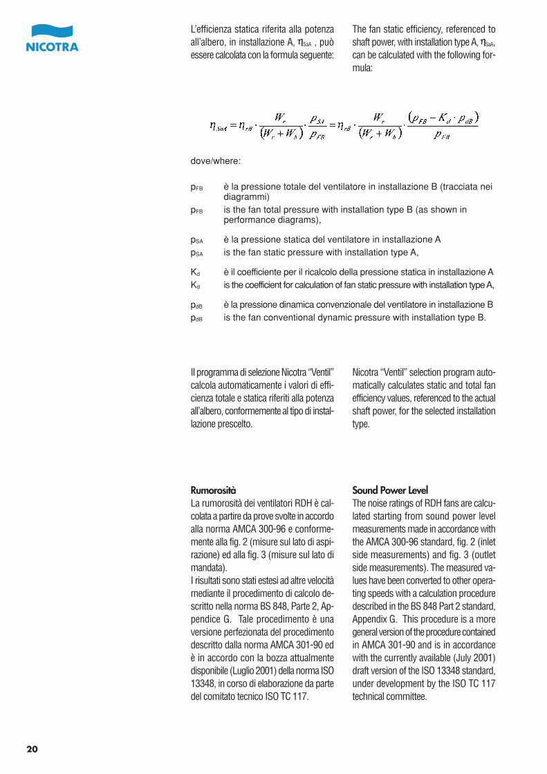
L’efficienza statica riferita alla potenzaall’albero, in installazione A, SaA , puòessere calcolata con la formula seguente:
The fan static efficiency, referenced toshaft power, with installation type A, SaA,can be calculated with the following for-mula:
20
dove/where:
pFB è la pressione totale del ventilatore in installazione B (tracciata nei diagrammi)
pFB is the fan total pressure with installation type B (as shown in performance diagrams),
pSA è la pressione statica del ventilatore in installazione ApSA is the fan static pressure with installation type A,
Kd è il coefficiente per il ricalcolo della pressione statica in installazione AKd is the coefficient for calculation of fan static pressure with installation type A,
pdB è la pressione dinamica convenzionale del ventilatore in installazione BpdB is the fan conventional dynamic pressure with installation type B.
Il programma di selezione Nicotra “Ventil”calcola automaticamente i valori di effi-cienza totale e statica riferiti alla potenzaall’albero, conformemente al tipo di instal-lazione prescelto.
Nicotra “Ventil” selection program auto-matically calculates static and total fanefficiency values, referenced to the actualshaft power, for the selected installationtype.
RumorositàLa rumorosità dei ventilatori RDH è cal-colata a partire da prove svolte in accordoalla norma AMCA 300-96 e conforme-mente alla fig. 2 (misure sul lato di aspi-razione) ed alla fig. 3 (misure sul lato dimandata).I risultati sono stati estesi ad altre velocitàmediante il procedimento di calcolo de-scritto nella norma BS 848, Parte 2, Ap-pendice G. Tale procedimento è unaversione perfezionata del procedimentodescritto dalla norma AMCA 301-90 edè in accordo con la bozza attualmentedisponibile (Luglio 2001) della norma ISO13348, in corso di elaborazione da partedel comitato tecnico ISO TC 117.
Sound Power LevelThe noise ratings of RDH fans are calcu-lated starting from sound power levelmeasurements made in accordance withthe AMCA 300-96 standard, fig. 2 (inletside measurements) and fig. 3 (outletside measurements). The measured va-lues have been converted to other opera-ting speeds with a calculation proceduredescribed in the BS 848 Part 2 standard,Appendix G. This procedure is a moregeneral version of the procedure containedin AMCA 301-90 and is in accordancewith the currently available (July 2001)draft version of the ISO 13348 standard,under development by the ISO TC 117technical committee.
El rendimiento estático referido a la po-tencia en el eje, en instalación A SaA,puede ser calculado con la fórmula si-guiente:
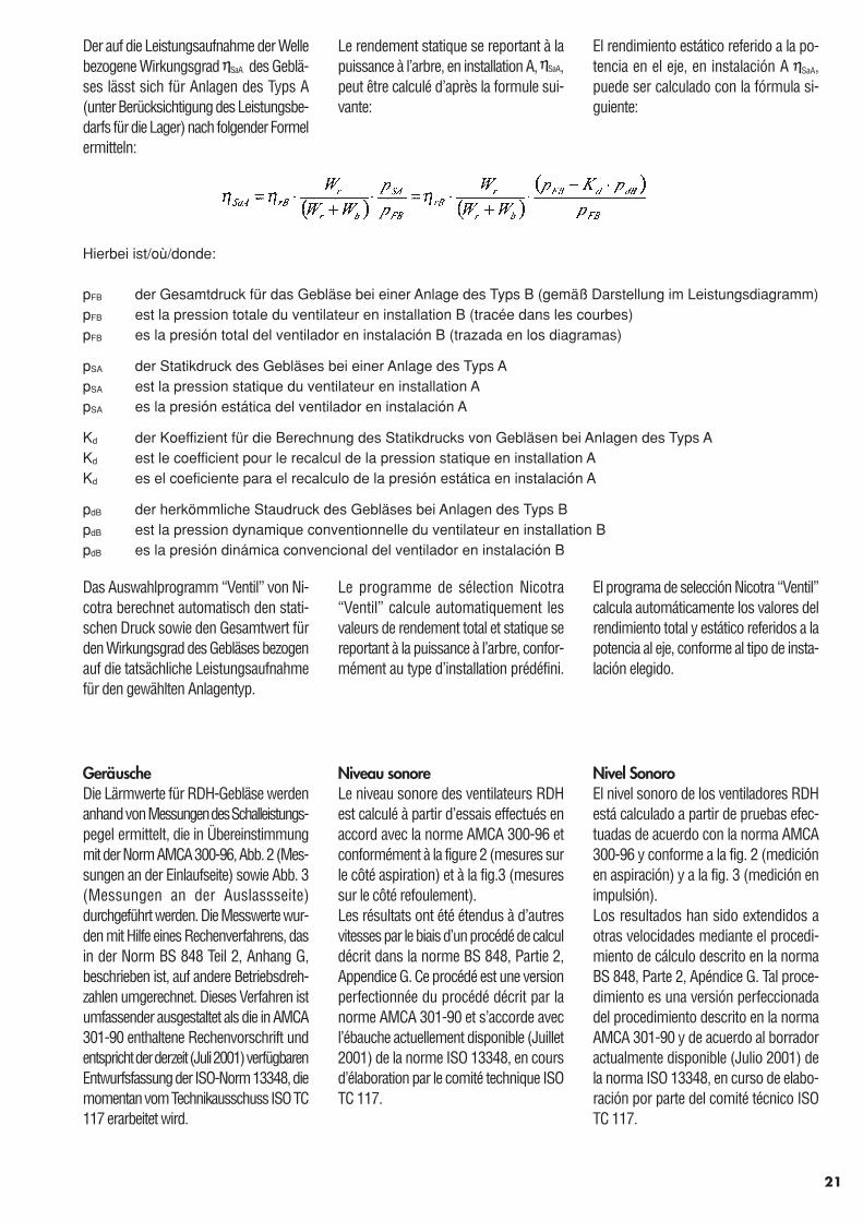
Der auf die Leistungsaufnahme der Wellebezogene Wirkungsgrad SaA des Geblä-ses lässt sich für Anlagen des Typs A(unter Berücksichtigung des Leistungsbe-darfs für die Lager) nach folgender Formelermitteln:
Hierbei ist/où/donde:
pFB der Gesamtdruck für das Gebläse bei einer Anlage des Typs B (gemäß Darstellung im Leistungsdiagramm)pFB est la pression totale du ventilateur en installation B (tracée dans les courbes)pFB es la presión total del ventilador en instalación B (trazada en los diagramas)
pSA der Statikdruck des Gebläses bei einer Anlage des Typs ApSA est la pression statique du ventilateur en installation ApSA es la presión estática del ventilador en instalación A
Kd der Koeffizient für die Berechnung des Statikdrucks von Gebläsen bei Anlagen des Typs AKd est le coefficient pour le recalcul de la pression statique en installation AKd es el coeficiente para el recalculo de la presión estática en instalación A
pdB der herkömmliche Staudruck des Gebläses bei Anlagen des Typs BpdB est la pression dynamique conventionnelle du ventilateur en installation BpdB es la presión dinámica convencional del ventilador en instalación B
Das Auswahlprogramm “Ventil” von Ni-cotra berechnet automatisch den stati-schen Druck sowie den Gesamtwert fürden Wirkungsgrad des Gebläses bezogenauf die tatsächliche Leistungsaufnahmefür den gewählten Anlagentyp.
El programa de selección Nicotra “Ventil”calcula automáticamente los valores delrendimiento total y estático referidos a lapotencia al eje, conforme al tipo de insta-lación elegido.
GeräuscheDie Lärmwerte für RDH-Gebläse werdenanhand von Messungen des Schalleistungs-pegel ermittelt, die in Übereinstimmungmit der Norm AMCA 300-96, Abb. 2 (Mes-sungen an der Einlaufseite) sowie Abb. 3(Messungen an der Auslassseite)durchgeführt werden. Die Messwerte wur-den mit Hilfe eines Rechenverfahrens, dasin der Norm BS 848 Teil 2, Anhang G,beschrieben ist, auf andere Betriebsdreh-zahlen umgerechnet. Dieses Verfahren istumfassender ausgestaltet als die in AMCA301-90 enthaltene Rechenvorschrift undentspricht der derzeit (Juli 2001) verfügbarenEntwurfsfassung der ISO-Norm 13348, diemomentan vom Technikausschuss ISO TC117 erarbeitet wird.
Nivel SonoroEl nivel sonoro de los ventiladores RDHestá calculado a partir de pruebas efec-tuadas de acuerdo con la norma AMCA300-96 y conforme a la fig. 2 (mediciónen aspiración) y a la fig. 3 (medición enimpulsión).Los resultados han sido extendidos aotras velocidades mediante el procedi-miento de cálculo descrito en la normaBS 848, Parte 2, Apéndice G. Tal proce-dimiento es una versión perfeccionadadel procedimiento descrito en la normaAMCA 301-90 y de acuerdo al borradoractualmente disponible (Julio 2001) dela norma ISO 13348, en curso de elabo-ración por parte del comité técnico ISOTC 117.
Le rendement statique se reportant à lapuissance à l’arbre, en installation A, SaA,peut être calculé d’après la formule sui-vante:
Le programme de sélection Nicotra“Ventil” calcule automatiquement lesvaleurs de rendement total et statique sereportant à la puissance à l’arbre, confor-mément au type d’installation prédéfini.
Niveau sonoreLe niveau sonore des ventilateurs RDHest calculé à partir d’essais effectués enaccord avec la norme AMCA 300-96 etconformément à la figure 2 (mesures surle côté aspiration) et à la fig.3 (mesuressur le côté refoulement).Les résultats ont été étendus à d’autresvitesses par le biais d’un procédé de calculdécrit dans la norme BS 848, Partie 2,Appendice G. Ce procédé est une versionperfectionnée du procédé décrit par lanorme AMCA 301-90 et s’accorde avecl’ébauche actuellement disponible (Juillet2001) de la norme ISO 13348, en coursd’élaboration par le comité technique ISOTC 117.
21
Sui diagrammi sono riportate le curve dilivello di potenza sonora pesata A(Lws7(A)) riferita al lato di aspirazione delventilatore.
Altri parametri acustici del ventilatoresono: il livello di potenza sonora pesataA sul lato di mandata Lws4(A), il livello dipotenza sonora di ciascuna banda d’ottavasul lato di aspirazione, Lws7-Oct, oppuresul lato di mandata, Lws4-Oct, il livello dipotenza sonora totale sul lato di aspira-zione, Lws7 , e sul lato di mandata, Lws4.Valori ragionevolmente approssimati diqueste grandezze possono essere calcolatisommando al valore di Lws7(A), letto suldiagramma in corrispondenza del puntodi lavoro, i valori degli appropriati diffe-renziali riportati in appendice.
The LWS curves on the fan performancediagrams show the fan A-weighted SoundPower Level (Lws7(A)) on the inlet side.
Other parameters representing the acou-stic performance of the fan are the outletside, A-weighted sound power levelLws4(A), the Octave-band sound powerlevel on inlet side, Lws7-Oct, or on outletside, Lws4-Oct, and the linearly weightedsound power level on inlet side, Lws7, oroutlet side, Lws4.Reasonably approximated values of theseparameters can be calculated by adding,to the value of Lws7(A), read on the dia-gram at the corresponding operatingpoint, the appropriate corrections shownin appendix.
22
Dove il pedice “Oct” indica valori specifici per ciascuna banda d’ottava.Where “Oct” means a specific value for each octave band.
Valori più precisi si possono ottenere conl’applicazione esatta del procedimento dicalcolo previsto dalla norma BS 848 Parte2 app. G. Il programma di selezione Ventilesegue integralmente questi calcoli efornisce la migliore approssimazione deirisultati.
Better approximations can be achievedwith the complete application of the cal-culation procedure described in the BS848 Part 2 standard, appendix G. TheVentil selection program carries out inte-grally these calculations, and gives thebest approximation of the results.
En los diagramas de los ventiladores estánindicadas las curvas de nivel de potenciasonora pesa A (Lws7(A)) referida al ladode aspiración del ventilador.
Otros parámetros acústicos del ventiladorson: el nivel de potencia sonora pesadaA en el lado de la impulsión Lws4(A), elnivel de potencia sonora de cada una delas bandas de octavas en el lado de aspi-ración, Lws7-Oct, o en el lado de impulsión,Lws4-Oct, el nivel de potencia sonora totalen el lado de aspiración, Lws7 , y en ellado de impulsión, Lws4 .Valores razonablemente aproximados deestos tamaños pueden ser calculadossumando al valor de Lws7(A), leído en eldiagrama en correspondencia con el puntode trabajo, los valores apropiados dife-renciales indicados en apéndice.
Die LWS-Kurven auf den Leistungsdia-grammen zeigen den für A gewichtetenSchalleistungspegel (Lws7(A)) des Geblä-ses auf der Einlassseite.
Weitere Parameter zu den akustischenWerten des Gebläses sind der für Agewichtete Schalleistungspegel Lws4(A)auf der Auslassseite; der Schalleistungs-pegel des Oktavbandes auf der EinlassseiteLws7-Oct bzw. auf der Auslassseite Lws4-Oct ;sowie die linear gewichteten Schalleis-tungspegel für die Einlassseite (Lws7)bzw. die Auslassseite (Lws4).Ausreichend genaue Näherungswerte fürdiese Parameter lassen sich dadurchermitteln, dass zum Wert Lws7(A), dersich laut Diagramm für den betreffendenArbeitspunkt ergibt, die im Anhangaufgeführten Berichtigungswerte addiertwerden.
Bessere Näherungswerte lassen sich beiAnwendung des vollständigen Rechen-verfahrens erzielen, das in der Norm BS848 Teil 2, Anhang G, beschrieben ist.Das Auswahlprogramm “Ventil” führtdiese Berechnungen vollständig durchund liefert den besten Näherungswert fürdie einzelnen Ergebnisse.
Pueden obtenerse valores más precisoscon la aplicación del procedimiento decálculo previsto por la norma BS 848 p.2 ap G. El programa de selección Ventilsigue íntegramente estos cálculos y su-ministra la mejor aproximación de losresultados.
Hierbei ist “Oct” ein bestimmter Wert für das jeweilige Oktavband.Où “Oct” indique les valeurs spécifiques par bandes d’octaves.
Donde el subíndice “Oct” indica valores específicos para cada banda de octavas.
Sur les diagrammes sont reportées lescourbes de niveau de puissance sonoremesurée A (Lws7 (A)) concernantl’aspiration du ventilateur.
Autres paramètres acoustiques du venti-lateur : le niveau de puissance sonoremesurée A au refoulement Lws4 (A), leniveau de puissance sonore par bandesd’octaves à l’aspiration, Lws7-Oct, ou aurefoulement, Lws4-Oct, le niveau de puis-sance sonore totale à l’aspiration, Lws7
et au refoulement, Lws4.Des valeurs raisonnablement proches deces tailles peuvent être calculées en ajou-tant à la valeur Lws7(A) relevée sur lediagramme en correspondance avec lepoint de fonctionnement, les valeurs descalculs différentiels appropriés reportésen appendice.
On peut obtenir des valeurs plus précisesen appliquant le procédé de calcul prévupar la norme BS 848 partie 2 app. G. Leprogramme de sélection Ventil réaliseintégralement ces calculs et fournit lesrésultats les plus rapprochants.
23
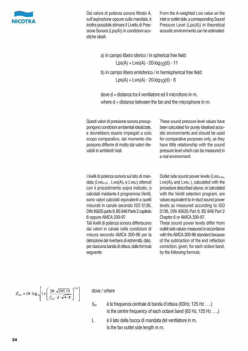
Dal valore di potenza sonora filtrato A,sull’aspirazione oppure sulla mandata, èinoltre possibile stimare il Livello di Pres-sione Sonora (Lps(A)) in condizioni acu-stiche ideali:
24
Questi valori di pressione sonora presup-pongono condizioni ambientali idealizzate,e dovrebbero essere impiegati a soloscopo comparativo, dal momento chepossono differire di molto dai valori rile-vabili in ambienti reali.
From the A-weighted Lws value on theinlet or outlet side, a corresponding SoundPressure Level (Lps(A)) in theoreticalacoustic environments can be estimated:
These sound pressure level values havebeen calculated for purely idealised acou-stic environments and should be usedfor comparative purposes only, as theyhave little relationship with the soundpressure level which can be measured ina real environment.
a) in campo libero sferico / in spherical free field:Lps(A) = Lws(A) - 20·log10(d) - 11
b) in campo libero emisferico / in hemispherical free field:Lps(A) = Lws(A) - 20·log10(d) - 8
dove d = distanza tra il ventilatore ed il microfono in m.where d = distance between the fan and the microphone in m.
I livelli di potenza sonora sul lato di man-data (Lws4-Oct , Lws(A)4 e Lws4) ottenuticon il procedimento sopra indicato, ocalcolati mediante il programma Ventil,sono valori calcolati equivalenti a quellimisurati in canale secondo ISO 5136,DIN 45635 parte 9, BS 848 Parte 2 capitolo6 oppure AMCA 330-97.Tali livelli di potenza sonora differisconodai valori in canale nelle condizioni dimisura secondo AMCA 300-96 per ladetrazione del riverbero di estremità, dato,per ciascuna banda di ottava, dalla formulaseguente:
Outlet side sound power levels (Lws4-Oct,Lws(A)4 and Lws4 ), calculated with theprocedure described above, or calculatedwith the Ventil selection program, arevalues equivalent to in-duct sound powerlevels as measured according to ISO5136, DIN 45635 Part 9, BS 848 Part 2Chapter 6 or AMCA 330-97.These sound power levels differ fromoutlet side values measured in accordancewith the AMCA 300-96 standard becauseof the subtraction of the end reflectioncorrection, given, for each octave band,by the following formula:
dove / where
fOct è la frequenza centrale di banda d’ottava (63Hz, 125 Hz ….)is the centre frequency of each octave band (63 Hz, 125 Hz ….)
L è il lato della bocca di mandata del ventilatore in m.is the fan outlet side length in m.
Del valor de Potencia Sonora filtrada A,en aspiración o en impulsión, es tambiénposible estimar el Nivel de Presión Sonora(Lps(A)) en condiciones acústicas ideales:
Ausgehend von einem für A gewichtetenLWS-Wert auf der Einlass- oder Auslass-seite lässt sich ein entsprechender Schall-druckpegel (Lps(A)) für theoretische Aku-stikverhältnisse abschätzen:
a) in einem freien, sphärischen Bereich / en champ libre sphérique / en campo libre esférico:Lps(A) = Lws(A) - 20·log10(d) - 11
b) in einem freien, hemisphärischen Bereich / en champ libre hémisphérique / en campo libre hemisférico:Lps(A) = Lws(A) - 20·log10(d) - 8
Hierbei ist d = der Abstand zwischen dem Gebläse und dem Mikrofon in m.où d = distance entre le ventilateur et le micro en m.donde d = distancia entre el ventilador y el micrófono en m.
Die Schalldruckpegelwerte wurden füridealisierte akustische Verhältnisse be-rechnet und sollten daher nur zu Verglei-chszwecken herangezogen werden, dasie mit unter realen Bedingungen ermit-telten Messwerten kaum etwas gemeinhaben.
Estos valores de presión sonora presu-ponen condiciones ambientales idealiza-das, y deberían ser utilizados solo a títulocomparativo, desde el momento quepueden diferir mucho de los valores obte-nibles en ambientes reales.
Nach dem obigen Verfahren bzw. mitdem Wahlprogramm „Ventil“ berechneteWerte für den Schalleistungspegel aufder Auslassseite (Lws4-Oct , Lws(A)4 undLws4 ) entsprechen den in der Luftführunggemäß ISO 5136, DIN 45635 Teil 9, BS848 Teil 2, Kapitel 6, bzw. AMCA 330-97gemessenen Werten.Diese Werte für den Schalleistungspegelunterscheiden sich nach der Norm AMCA300-96 von den Messwerten auf derAuslassseite durch den Abzug des Berich-tigungswertes für das Endecho, der sichfür die einzelnen Oktavbänder aus folgen-der Formel ergibt:
Los niveles de potencia sonora en el ladode impulsión (Lws4-Oct , Lws(A)4 y Lws4 )obtenidos con el procedimiento arribaindicado, o calculados mediante el pro-grama Ventil, son valores calculadosequivalentes a los valores medidos enconducto según ISO 5136, DIN 45635parte 9, BS 848 Parte 2 capítulo 6 o AMCA330-97. Tales valores de potencia sonoradifieren de los valores en conducto en lascondiciones de medida según AMCA 300-96 por la sustracción de los valoresextremos de reverberación, dados, paracada una de las bandas de octavas, porla formula siguiente:
hierbei ist / où / donde
fOct die Mittelfrequenz für jedes Oktavband (63 Hz, 125 Hz …)est la fréquence centrale par bandes d’octaves (63 Hz, 125 Hz…)es la frecuencia central de la banda de octavas (63Hz, 125Hz ...)
L die Länge der Auslassseite des Gebläses in m.est le côté du refoulement du ventilateur en m.es el lado de la boca de impulsión del ventilador en m.
D’après la valeur de puissance sonorefiltrée A, à l’aspiration ou au refoulement,il est aussi possible d’estimer le Niveaude Pression sonore (Lps(A)) dans desconditions acoustiques idéales:
Ces valeurs de pression sonore supposentdes conditions climatiques idéales et nedoivent être utilisées que dans un butcomparatif, car elles peuvent être trèsdifférentes des valeurs relevées par me-sures effectuées dans les conditions réel-les.
Les niveaux de puissance sonore aurefoulement (Lws4-Oct, Lws(A)4 et Lws4)obtenus avec le procédé indiqué ci-dessus,ou calculés au moyen du programmeVentil sont des valeurs calculées équiva-lentes à celles mesurées canalisées selonISO 5136, DIN 45635 partie 9, BS 848Partie 2 chapitre 6 ou AMCA 330-97.Ces niveaux de puissance sonore diffèrentdes valeurs canalisées dans les conditionsde mesures selon AMCA 300-96 pour ladéduction de la réflexion d’extrémité don-née par bandes d’octaves par la formulesuivante :
25
Nell’applicazione pratica, è importantericordare che la rumorosità del ventilatoreinstallato può variare anche di moltorispetto ai livelli registrati in condizioni dilaboratorio.Vibrazioni meccaniche alle frequenze dirotazione del ventilatore e del motore,oppure alle frequenze di vibrazione internadi quest’ultimo, possono facilmente irra-diare rumore estraneo al ventilatore, ge-neralmente con picchi ben definiti infrequenza.La risposta meccanica del ventilatore allevibrazioni indotte è, inoltre, fortementeinfluenzata dalla rigidezza dei supporti edel telaio di basamento che lo collega almotore.Trafilamenti d’aria nei raccordi, o turbo-lenze generate da griglie di protezione odi diffusione, da protezioni della trasmis-sione o da raccordi nei canali possonoalterare apprezzabilmente anche il rumoreaerodinamico a larga banda, e special-mente ad alta frequenza.Per finire, l’ampiezza della pulsazione allafrequenza di passaggio pala può cambiarenotevolmente, anche di molti decibel, pereffetto delle condizioni di risonanza chepossono verificarsi nel canale o nellacamera a valle di un ventilatore.Nella maggioranza dei casi, l’incrementodi rumorosità a larga banda derivantedalle condizioni di installazione reale ècontenuto in circa 2 dB. Più difficile èprevedere l’incremento di rumorosità chepuò prodursi per effetto delle vibrazionimeccaniche, che dipende dalle caratteri-stiche degli altri elementi meccanici im-piegati (basamento, motore, pulegge), el’esatta rumorosità alla frequenza di pas-saggio pala, che può aumentare o dimi-nuire per effetto delle caratteristiche acu-stiche dei canali connessi al ventilatore.
26
The user should remember that the soundpower level of a fan, as installed in practice,could be significantly higher than thatmeasured in laboratory conditions.Mechanical vibrations at the rotationfrequencies of the fan and of the drivingmotor, and at the internal vibration fre-quencies of the same motor can easilyradiate noise which is not actually produ-ced by the fan, usually with narrow peaksat well defined frequencies.The mechanical reaction of the fan struc-ture to induced vibrations is highly influen-ced by the stiffness of the base frameholding together fan and motor.Air leakage through the connections, orturbulence produced by guards, diffusergrids or transition pieces can also signifi-cantly change the broadband noisespectrum, particularly at high frequency.As a final note, the actual amplitude ofthe blade passing frequency peak can bechanged by many decibels as an effectof the acoustic resonance properties ofthe duct or plenum connected to the fan.In most cases, the broadband noise levelincrease, produced by a reasonable real-life installation, is kept within 2 dBW.Much more difficult may be the predictionof the noise increase produced by mecha-nical vibrations, as this depends on themechanical characteristics of many othercomponents (base frame, motor, pulleysand so on), and of the blade passingfrequency tone, which depends on theacoustic properties of the duct system.
Der Anwender sollte sich dabei vor Augenhalten, dass der Schalleistungspegel einesreal eingebauten Gebläses in der Praxiserheblich höher liegen kann als bei Mes-sungen unter Laborbedingungen.Mechanische Schwingungen bei denDrehzahlen des Gebläses sowie des An-triebsmotors und die Vibrationsfrequenzenim Inneren des gleichen Motors könnenohne weiteres Lärm abstrahlen, der nichtunmittelbar auf das Gebläsezurückzuführen ist und üblicherweise engeingegrenzte Spitzenwerte bei genau defi-nierten Frequenzen aufweist. Die durchinduzierte Vibrationen ausgelösten mecha-nischen Wirkungen für die Gebläsestrukturwerden im hohen Maße durch die Steifig-keit der Rahmenstruktur beeinflusst, indie Gebläse und Motor eingebaut sind.Luftverluste durch Anschlüsse bzw. Ver-wirbelungen, die auf Schutzvorrichtungen,Diffusorgitter oder Übergangsteilezurückzuführen sind, können das Breit-bandspektrum für den Lärm insbesonderebei hohen Frequenzen signifikant abän-dern.Abschließend ist zu sagen, dass die tat-sächliche Amplitude der Frequenzspitzenfür die Lüfterblätter sich auf Grund derResonanzeigenschaften des Untergrundsbzw. der Lüftungskanäle ändern kann, andenen das Gebläse befestigt ist. In denmeisten Fällen lässt sich die breitbandigeGeräuschpegelzunahme, die von einertatsächlich installierten Anlage ausgeht,auf höchstens 2 dBW beschränken. Sehrviel schwieriger ist unter Umständen dieVorhersage der Lärmzunahme, die aufmechanische Schwingungenzurückzuführen ist, da dieser Wert vonden mechanischen Kennwerten zahlrei-cher weiterer Baugruppen (Grundrahmen,Motor, Riemenscheiben usw.) sowie vonder Frequenz beim Lüfterraddurchsatzabhängig ist, die von den akustischenEigenschaften der Lüftungskanäle bestim-mt wird.
En la aplicación práctica, es importanterecordar que el nivel sonoro del ventiladorinstalado puede variar también muchorespecto a los niveles registrados encondiciones de laboratorio.Las vibraciones mecánicas a la frecuenciade rotación del ventilador y del motor ya la frecuencia de vibración interna deeste ultimo, pueden fácilmente irradiarruidos extraños al ventilador, generalmentecon picos bien definidos en frecuencia.La respuesta mecánica del ventilador alas vibraciones inducidas está tambiénfuertemente influenciada por la rigidez delos soportes y de la bancada que lo uneal motor.Perdidas de aire en la embocadura, oturbulencias generadas por rejillas deprotección o de difusión, de proteccionesde la transmisión o de empalmes en elconducto pueden alterar apreciablementetambién el ruido aerodinámico en bandaalta y especialmente a alta frecuencia.Para terminar, la amplitud de la pulsacióna la frecuencia de paso de pala puedecambiar notablemente, incluso de muchosdecibelios, por efecto de las condicionesde resonancia que pueden verificarse enel conducto o en la cámara que sigue alventilador.En la mayoría de los casos, el incrementodel nivel sonoro en banda alta derivadasde las condiciones de instalación real estácomprendido en cerca de 2 dB. Mas difíciles prever el incremento de nivel sonoroque puede producirse por efecto de lasvibraciones mecánicas, que dependen delas características de los otros elementosmecánicos empleados (bancadas, motor,poleas), y el nivel sonoro exacto a lafrecuencia de paso de pala, que puedeaumentar o disminuir por efecto de lascaracterísticas acústicas de los conductosconectados al ventilador.
Dans l’application pratique, il est importantde noter que le niveau sonore du ventila-teur installé peut varier énormément parrapport aux niveaux enregistrés dans lesconditions de laboratoire.Des vibrations mécaniques dues auxfréquences de rotation du ventilateur etdu moteur ou aux fréquences de vibrationinterne de ce dernier, peuvent facilementdiffuser des bruits étrangers au ventilateuret généralement avec des pics bien définisen fréquence. La réponse mécanique duventilateur aux vibrations induites estfortement influencée par la rigidité dessupports et du cadre de base qui le relieau moteur.Des fuites d’air dans les raccordementsou des turbulences générées par les grillesde protection ou de diffusion ou par lesraccordements des canalisations peuventaltérer considérablement le bruit aérody-namique à larges bandes et spécialementà haute fréquence.Pour finir, l’importance de la pulsation dela fréquence du passage de l’aube peutégalement varier considérablement deplusieurs décibels à cause des conditionsde résonance produites dans les gainesou dans la pièce en aval d’un ventilateur.Dans la plupart des cas, l’augmentationdu niveau sonore par large banded’octaves découlant des conditionsd’installation réelle est contenue dansenviron 2 dB. Il est plus difficile de prévoirl’augmentation du niveau sonore pouvantse produire par effet des vibrations méca-niques, qui dépend des caractéristiquesdes autres éléments mécaniques utilisés(support, moteur, poulies) et le niveausonore exact à la fréquence de passagedes aubes pouvant augmenter ou dimi-nuer à cause des caractéristiques acou-stiques des gaines reliées au ventilateur.
27
28
Zona di normale impiegoIl diagramma di funzionamento dei ven-tilatori RDH è diviso in tre zone da duerighe rosse parallele alle linee di efficienzacostante. Le due righe rosse delimitanola zona di normale impiego del ventilatore(al centro) dalla zona di stallo (in alto asinistra) e dalla zona di bassa pressione(in basso a destra). Un dimensionamentocorretto del ventilatore porta ad avere ilpunto di funzionamento entro la zona dinormale impiego, e preferibilmente sullalinea di massima efficienza o lievementepiù a destra.La scelta di una grandezza di ventilatoreche comporta un punto di funzionamentonella zona di bassa pressione è sconsi-gliata, sia a causa della scarsa efficienzaraggiungibile, che della maggiore incer-tezza delle prestazioni (si veda a questoproposito la norma DIN 24166).Per correggere un dimensionamento diquesto tipo, occorre scegliere un ventila-tore di grandezza maggiore, un ventilatorebinato oppure passare da un ventilatorepala rovescia ad un ventilatore pala avanti.La scelta di un ventilatore con il punto difunzionamento nella zona di stallo è daevitarsi accuratamente: qualunque venti-latore che operi in queste condizioni nonè solo scarsamente efficiente, ma produceuna pressione fluttuante ed una fortecomponente di rumore a bassa pressione,che incide scarsamente sul valore dellivello di potenza sonora totale filtrato A,ma che può rivelarsi assai fastidioso. Ilproblema può essere agevolmente pre-venuto scegliendo un ventilatore di gran-dezza più piccola.
Normal operation areaThe performance diagram of RDH fansis divided into three areas by two redlines, parallel to the constant efficiencylines. The two red lines separate thenormal operating area of the fan (in themiddle), from the stall region (top-leftarea) and from the low-pressure region(bottom-right area).An appropriate selection of the fan sizegives an operating point within the normaloperation area of the fan, and, ideally, onor slightly right of the best efficiency lineof the fan.A fan size selection producing an operatingpoint in the low pressure area of thediagram should preferably be avoided,because of both the low efficiency andthe larger uncertainty of the fan perfor-mance (see also DIN 24166 on this su-bject).To rectify such a selection, a larger fansize or a twin fan should be used, or aforward curved fan should be substitutedto a similarly sized RDH backward inclinedone.A fan size selection with the operatingpoint in the stall region should be carefullyavoided: any fan operating in these con-ditions is not only scarcely efficient, butalso generates a fluctuating pressure anda high noise level in the lower frequencyoctaves, which gives little contribution tothe A-weighted total noise level, but maybe highly annoying. Such a fan choicecan be easily rectified selecting a smallerfan size.
Normaler BetriebsbereichDas Leistungsdiagramm von RDH-Gebläsen wird durch zwei rote Linien, dieparallel zu den Linien für die Wirksamkeits-konstante verlaufen, in drei Bereiche un-tergliedert. Die beiden roten Linien trennenden normalen Betriebsbereich eines Ge-bläses (in der Mitte) vom Abreißbereich(oben links) und dem Unterdruckbereich(unten rechts). Eine geeignete Größenaus-wahl für das Gebläse entspricht einemArbeitspunkt, der innerhalb des Bereichsfür den Normalbetrieb liegt und idealer-weise auf oder etwas rechts von der Liniefür die beste Wirksamkeit des Gebläsesliegen sollte.Eine Gebläseauswahl, die zu einem Arbeits-punkt im Unterdruckbereich des Diagram-ms führt, sollte vorzugsweise vermiedenwerden, und zwar sowohl wegen desniedrigen Wirkungsgrades und dergrößeren Ungewissheit hinsichtlich derGebläseleistung (siehe hierzu auch DIN24166). Um einen derartigen Fehler zubeheben, sollte ein größeres Gebläse oderein Zwillingsgebläse eingesetzt werden;alternativ können auch die nach rückwärtsgeneigten Lüfterblätter eines RDH-Gebläses gleicher Größe durch nachvorwärts geneigte Lüfterblätter ersetztwerden.Besonders ist darauf zu achten, dass dieGebläsewahl nicht zu einem Arbeitspunktim Abreißbereich führt: Jedes Gebläse,das unter derartigen Bedingungen arbeitenmuss, ist nicht nur wenig effizient, sondernerzeugt auch schwankenden Druck undeinen hohen Geräuschpegel in den unterenOktaven; dies trägt zwar kaum zum ge-samten Geräuschpegel einer für A gerich-teten Anlage bei, kann jedoch sehr lästigsein. Der Fehler lässt sich problemlosdurch Einsatz eines kleineren Gebläsesbeheben.
Zona de empleo normalEl diagrama de funcionamiento de losventiladores RDH está dividido en treszonas por dos líneas rojas paralelas a laslíneas de rendimiento constante. Las doslíneas rojas delimitan la zona de empleonormal del ventilador (en el centro) de lazona crítica (en alto a la izquierda) y de lazona de baja presión (abajo a la derecha).Un dimensionamiento correcto del venti-lador lleva a tener el punto de trabajodentro de la zona de funcionamientonormal, y preferiblemente sobre la líneade máximo rendimiento o ligeramente ala derecha.La selección de un tamaño de ventiladorque comporta un punto de funcionamien-to en la zona de baja presión está desa-consejada ya sea por el escaso rendimien-to conseguido que por la mayorincertidumbre de las prestaciones (ver aeste propósito la norma DIN24166). Paracorregir un dimensionamiento de estetipo se debe seleccionar un ventiladorde mayor tamaño, un ventilador doble opasar de un ventilador de palas haciaatrás a un ventilador de palas hacia delante.Se debe poner cuidado en evitar la selec-ción de un ventilador con el punto detrabajo en la zona crítica: cualquier venti-lador que opere en estas condiciones nosolo es escasamente eficiente sino queproduce una presión fluctuante y unafuerte componente de ruido a baja presiónque incide escasamente sobre el valordel nivel de potencia sonora total filtradoA, pero que puede convertirse en muyfastidioso. El problema puede ser fácil-mente prevenido seleccionando un ven-tilador de un tamaño inferior.
Zone d’utilisation normaleLa courbe de fonctionnement des venti-lateurs RDH est divisée en trois zones pardeux lignes rouges parallèles à la lignede rendement constant. Les deux lignesrouges délimitent la zone normaled’utilisation du ventilateur (au centre) dela zone de perte de vitesse (en haut àgauche) et de la zone de basse pression(en bas à droite).Un dimensionnement correct du ventila-teur amène à avoir un point de fonction-nement entre la zone d’utilisation normaleet de préférence sur la ligne de rendementmaximum ou légèrement plus à droite.Le choix d’une taille de ventilateur com-portant un point de fonctionnement dansla zone de basse pression est déconseilléà cause du faible rendement ainsi quede la grande incertitude des performances(voir à ce sujet la norme DIN 24166).Pour corriger un dimensionnement dece type, il faut choisir un ventilateur detaille supérieure, un ventilateur double oupasser d’un ventilateur à réaction à unventilateur à action.Le choix d’un ventilateur ayant un pointde fonctionnement dans la zone de pertede vitesse est à éviter impérativement:tout ventilateur fonctionnant dans cesconditions est non seulement peu efficacemais produit aussi une pression fluctuanteet une forte composante de bruit à bassepression qui influe faiblement sur la valeurdu niveau de puissance sonore totalefiltrée A, (effet de pompage). Choisir dansce cas un ventilateur de plus petite taille.
29
30
TolleranzeI ventilatori RDH delle grandezze da 180a 315, hanno prestazioni aerauliche, erumorosità in condizioni di prova secondoAMCA 300-96, tali da rientrare nelle tolle-ranze indicate nella norma DIN 24166,Classe 2.I ventilatori RDH delle grandezze da 355a 1000 soddisfano le tolleranze prescrittedalla stessa norma per la Classe 1.
Prestazioni dei ventilatori binati G2Le prestazioni di un ventilatore binato,ovvero di una versione identificata dalprefisso "G2", si calcolano, a partire dalcorrispondente punto di lavoro di unventilatore singolo, applicando le formulesotto elencate.
Le prestazioni così calcolate non sonocertificate AMCA.
TolerancesRDH fans of the sizes from 180 to 315have air performance and sound powerlevels, as measured according to theAMCA 300-96 standard, within the tole-rances allowed by the DIN 24166 standardfor Class 2.RDH fans of the sizes from 355 upwardoperate within the performance tolerancesallowed by the same standard for Class 1.
Performance of twin fan units G2The performance of twin fan units, iden-tified by the “G2” prefix, can be calculated,starting from that in the correspondingoperating point of a single fan, with thefollowing formulas.
Fan performance so calculated is notAMCA Licensed.
- pressione / pressure: Pb = P x 1- portata / volume flow rate: Qb = Q x 2- potenza assorbita / impeller power: Wb = W x 2,15- numero di giri / fan speed: Nb = N x 1,05- rumorosità / Lws: Lwsb = Lws + 3 dB
The performance curves of the RDH fanshave been extended outside the normaloperation range to assist with troublesho-oting at system start-up time, but fanperformance in these conditions is subjectto increased uncertainty, also because ofthe influence of the air system connectedto the fan.
Le curve di funzionamento dei ventilatorisono estese fuori della zona di normaleimpiego con lo scopo di agevolare ladiagnosi degli impianti in fase di messain opera, ma le prestazioni dei ventilatoriin queste condizioni sono soggette anotevoli incertezze, dovute ancheall’influenza del sistema connesso al ven-tilatore.
ToleranzenRDH-Gebläse der Größen 180 bis 315verfügen über Durchsatzleistungen undSchalleistungspegel, die laut Messunggemäß der Norm AMCA 300-96 innerhalbder Toleranzen liegen, die laut DIN 24166für Anlagen der Klasse 2 zulässig sind.RDH-Gebläse in Größen ab 355 sindinnerhalb der Leistungstoleranzen zubetreiben, die für Klasse 1 der genanntenNorm gelten.
ToleranciasLos ventiladores RDH desde el tamaño180 al 315 tienen prestaciones aerólicasy niveles sonoros en condiciones deprueba según AMCA 300-96 tales queentran dentro de las tolerancias indicadasen la norma DIN 24166, Clase 2.Los ventiladores RDH desde el tamaño355 al 1000 satisfacen las toleranciasprescritas en la misma norma para laClase 1.
Die Leistungskurven für RDH-Gebläsewurden über den normalen Betriebsbe-reich hinaus verlängert, um bei der Feh-lersuche während des Anlaufs der Anlagebehilflich zu sein; Gebläseleistungen unterdiesen Bedingungen sind jedoch auchdeshalb sehr unsicher, weil die mit demGebläse verbundene Lüftungsanlage hierebenfalls die Parameter beeinflusst.
Las curvas de funcionamiento de losventiladores se extienden fuera de la zonade funcionamiento normal con el fin defacilitar el diagnostico de las instalacionesen fase de puesta en marcha, pero lasprestaciones de los ventiladores en estascondiciones están sujetas a notablesincertidumbres debidas también a la in-fluencia del sistema conectado al ventila-dor.
Leistungsdaten für Zwillingsgebläse-einheiten vom Typ G2Die Leistungsdaten für Zwillingsgebläse,die durch das Präfix “G2” gekennzeichnetsind, lassen sich ausgehend von denentsprechenden Werten für den Arbeits-punkt eines Einzelgebläses anhand fol-gender Formeln berechnen.
Für die Messung von Gebläseleistungennach diesem Verfahren liegt keine AMCA-Lizenz vor.
Prestaciones de los ventiladores doblesG2Las prestaciones de un ventilador doble,o sea las versiones identificadas por elprefijo “G2”, se calculan a partir del cor-respondiente punto de trabajo de unventilador simple, aplicando las formulasabajo indicadas.
Las prestaciones así calculadas no estáncertificadas AMCA.
- Druck / pression / presión: Pb = P x 1- Volumendurchfluss / débit / caudal: Qb = Q x 2- Lüfterradleistung / puissance absorbée / potencia absorbida: Wb = W x 2,15- Gebläsedrehzahl / nombre de tours / velocidad ventilador: Nb = N x 1,05- Lws / niveau sonore / nivel sonoro: Lwsb = Lws + 3 dB
TolérancesLes ventilateurs RDH de la taille 180 à315 ont, en conditions d’essais selonAMCA 300-96, des performances aérau-liques et des niveaux sonores qui peuventrentrer dans les tolérances indiquées dansla norme DIN 24166, Classe 2.Les ventilateurs RDH de la taille 355 à1000 satisfont les tolérances prescritespar la même norme pour la Classe 1.
Performances des ventilateurs doublesG2Les performances d’un ventilateur doubleidentifié par “G2” se calculent à partir dupoint de fonctionnement correspondantà un ventilateur simple en appliquant lesformules ci-dessous.
Les performances ainsi calculées ne sontpas certifiées AMCA.
Les courbes de fonctionnement des ven-tilateurs sont étendues hors de la zoned’utilisation normale dans le but de faciliterle diagnostic des installations en phasede montage mais les performances desventilateurs dans ces conditions sontsujettes à d’importantes incertitudes dûesaussi à l’influence du système relié auventilateur.
31
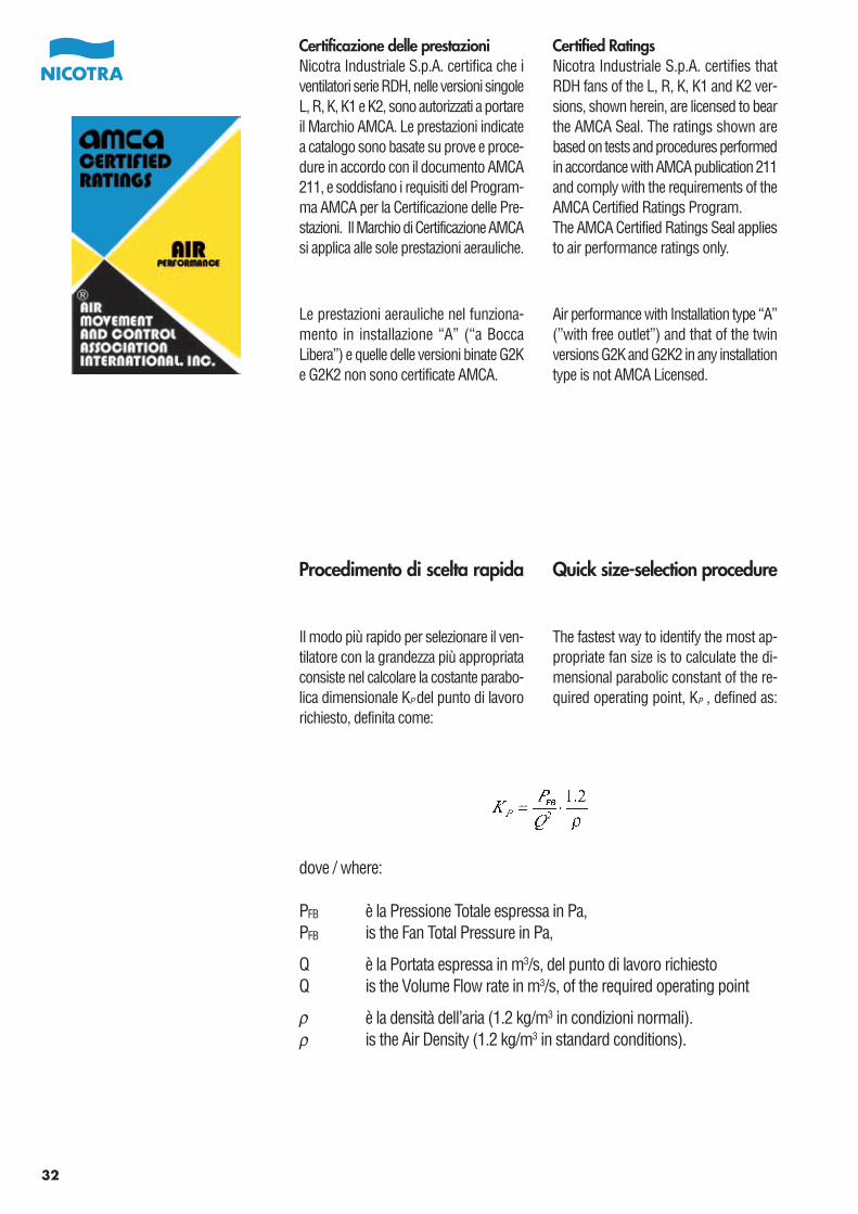
32
Certificazione delle prestazioniNicotra Industriale S.p.A. certifica che iventilatori serie RDH, nelle versioni singoleL, R, K, K1 e K2, sono autorizzati a portareil Marchio AMCA. Le prestazioni indicatea catalogo sono basate su prove e proce-dure in accordo con il documento AMCA211, e soddisfano i requisiti del Program-ma AMCA per la Certificazione delle Pre-stazioni. Il Marchio di Certificazione AMCAsi applica alle sole prestazioni aerauliche.
Le prestazioni aerauliche nel funziona-mento in installazione “A” (“a BoccaLibera”) e quelle delle versioni binate G2Ke G2K2 non sono certificate AMCA.
Certified RatingsNicotra Industriale S.p.A. certifies thatRDH fans of the L, R, K, K1 and K2 ver-sions, shown herein, are licensed to bearthe AMCA Seal. The ratings shown arebased on tests and procedures performedin accordance with AMCA publication 211and comply with the requirements of theAMCA Certified Ratings Program.The AMCA Certified Ratings Seal appliesto air performance ratings only.
Air performance with Installation type “A”(”with free outlet”) and that of the twinversions G2K and G2K2 in any installationtype is not AMCA Licensed.
Procedimento di scelta rapida
Il modo più rapido per selezionare il ven-tilatore con la grandezza più appropriataconsiste nel calcolare la costante parabo-lica dimensionale KP del punto di lavororichiesto, definita come:
Quick size-selection procedure
The fastest way to identify the most ap-propriate fan size is to calculate the di-mensional parabolic constant of the re-quired operating point, KP , defined as:
dove / where:
PFB è la Pressione Totale espressa in Pa,PFB is the Fan Total Pressure in Pa,
Q è la Portata espressa in m3/s, del punto di lavoro richiestoQ is the Volume Flow rate in m3/s, of the required operating point
è la densità dell’aria (1.2 kg/m3 in condizioni normali).is the Air Density (1.2 kg/m3 in standard conditions).
Bescheinigte LeistungsdatenNicotra Industriale S.p.A. bescheinigt,dass die hierin dargestellten RDH-Lüfterdes Typs L, R, K, K1 und K2 von derAMCA zur Führung ihres Siegels zugelas-sen sind. Die dargestellten Einstufungenberuhen auf Prüfungen und Verfahren,die gemäß AMCA-Druckschrift 211durchgeführt wurden und den Erforder-nissen eines von der AMCA zugelassenenEinstufungsprogramms entsprechen.
Das entsprechende AMCA-Siegel gilt nurfür die Luftdurchsatzleistungen.Der Luftdurchsatz bei Anlagen des “TypsA” (”ohne Luftführungselement amAuslass”) und die von Zwillingsgebläseneines beliebigen Anlagentyps G2K undG2K2 verfügen nicht über eine AMCA-Zulassung.
Certificación de las prestacionesNicotra Industriale S.p.A. certifica que losventiladores serie RDH, en las versionessimples L, R, K, K1 y K2, están autorizadaspara llevar el Sello AMCA. Las prestacio-nes indicadas en catálogo están basadasen pruebas y procedimientos de acuerdocon el documento AMCA 211, y satisfacenlos requisitos del Programa AMCA parala Certificación de las Prestaciones.
El Sello de Certificación AMCA se aplicasolo a las prestaciones aerólicas.Las prestaciones aerólicas en el funcio-namiento en instalación “A” (“a BocaLibre”) y aquellas de las versiones G2Ky G2K2 no están certificadas AMCA.
Certification des performancesNicotra Industriale SPA, certifie que lesversions simples L, R, K, K1, et K2 desventilateurs de la série RDH sont autorisésà porter la Marque AMCA. Les performan-ces indiquées au catalogue sont baséessur des essais et procédures en accordavec le document AMCA 211 et répondentaux demandes du Programme AMCApour la certification des performances.
La marque de certification AMCAs’applique aux seules performances aérau-liques.Les performances aérauliques en fonc-tionnement installation “A”(“BoucheBée”) et celles des versions doubles G2Ket G2K2 ne sont pas certifiées AMCA.
Kurzverfahren zur Größenau-swahl
Der schnellste Weg zur Ermittlung dergeeigneten Gebläsegröße besteht darin,die parabolische Maßkonstante für denbenötigten Arbeitspunkt KP zu berechnen,für den die Definition lautet:
Procedimiento de selecciónrápida
El modo más rápido de seleccionar ma-nualmente el ventilador con el tamañoapropiado consiste en calcular la constanteparabólica dimensional KP del punto detrabajo requerido, definida como:
Procédure de choix rapide
La façon la plus rapide de sélectionnerla taille la plus appropriée d’un ventilateurconsiste en calculer la constante parabo-lique dimensionnelle KP du point de fon-ctionnement demandé, définie ainsi :
hierbei ist / où / donde:
PFB der Gesamtwert für den Gebläsedruck in Pa,PFB est la Pression Totale exprimée en Pa,PFB es la Presión Total expresada en Pa,
Q der Volumendurchfluss in m3/s für den benötigten ArbeitspunktQ est le débit exprimé en m3/s du point de fonctionnement demandéQ es el Caudal expresado en m3/s, del punto de trabajo requerido
die Luftdichte (1,2 kg/m3 unter Normbedingungen).est la densité de l’air (1.2 kg/m3 en conditions normales).es la densidad del aire (1.2 kg/m3 en condiciones normales).
33
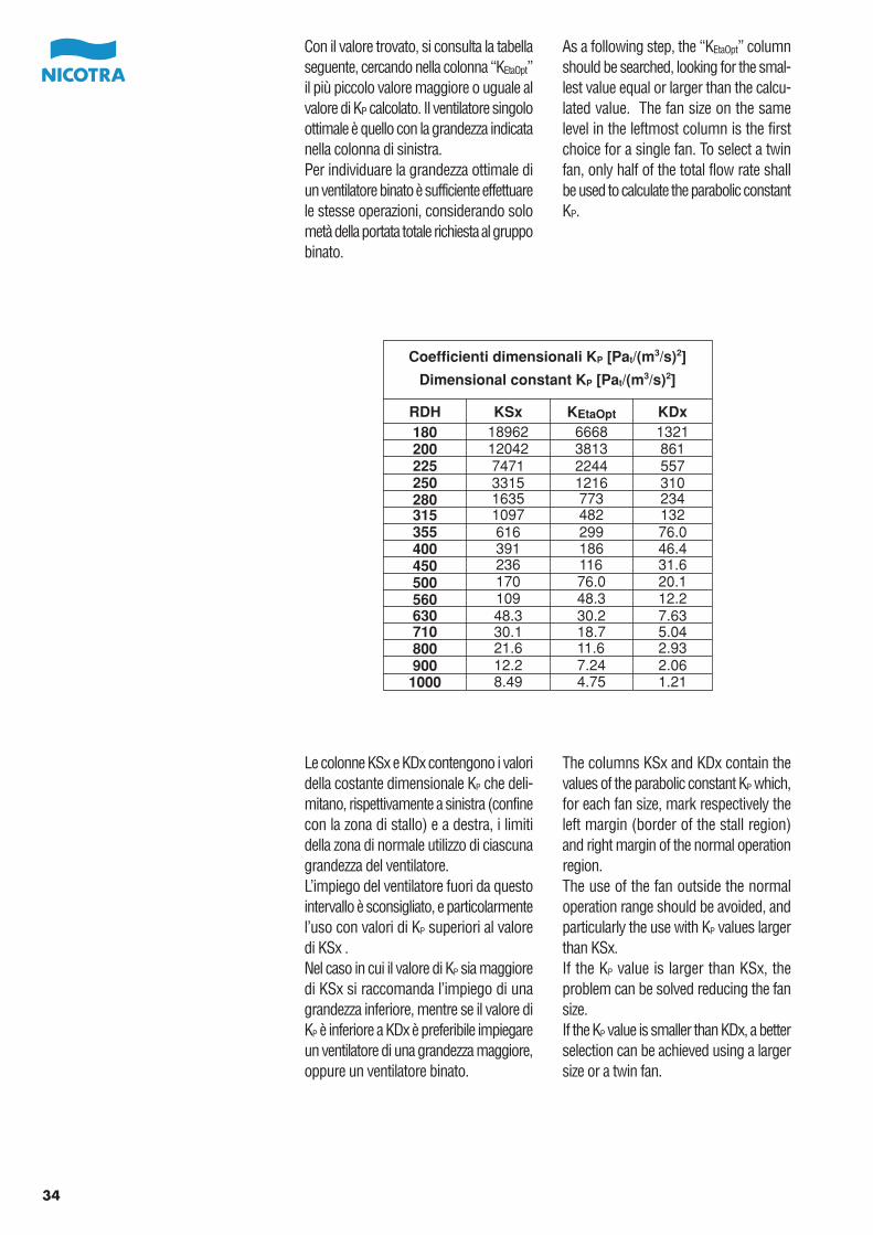
34
Con il valore trovato, si consulta la tabellaseguente, cercando nella colonna “KEtaOpt”il più piccolo valore maggiore o uguale alvalore di KP calcolato. Il ventilatore singoloottimale è quello con la grandezza indicatanella colonna di sinistra.Per individuare la grandezza ottimale diun ventilatore binato è sufficiente effettuarele stesse operazioni, considerando solometà della portata totale richiesta al gruppobinato.
As a following step, the “KEtaOpt” columnshould be searched, looking for the smal-lest value equal or larger than the calcu-lated value. The fan size on the samelevel in the leftmost column is the firstchoice for a single fan. To select a twinfan, only half of the total flow rate shallbe used to calculate the parabolic constantKP.
Coefficienti dimensionali KP [Pat/(m3/s)2]
Dimensional constant KP [Pat/(m3/s)2]
RDH180 18962 6668 1321
KSx KEtaOpt KDx
200225250280315355400450500560630710800900
1000
12042 3813 8617471 2244 5573315 1216 3101635 773 2341097 482 132616 299 76.0391 186 46.4236 116 31.6170 76.0 20.1109 48.3 12.248.3 30.2 7.6330.1 18.7 5.0421.6 11.6 2.9312.2 7.24 2.068.49 4.75 1.21
Le colonne KSx e KDx contengono i valoridella costante dimensionale KP che deli-mitano, rispettivamente a sinistra (confinecon la zona di stallo) e a destra, i limitidella zona di normale utilizzo di ciascunagrandezza del ventilatore.L’impiego del ventilatore fuori da questointervallo è sconsigliato, e particolarmentel’uso con valori di KP superiori al valoredi KSx .Nel caso in cui il valore di KP sia maggioredi KSx si raccomanda l’impiego di unagrandezza inferiore, mentre se il valore diKP è inferiore a KDx è preferibile impiegareun ventilatore di una grandezza maggiore,oppure un ventilatore binato.
The columns KSx and KDx contain thevalues of the parabolic constant KP which,for each fan size, mark respectively theleft margin (border of the stall region)and right margin of the normal operationregion.The use of the fan outside the normaloperation range should be avoided, andparticularly the use with KP values largerthan KSx.If the KP value is larger than KSx, theproblem can be solved reducing the fansize.If the KP value is smaller than KDx, a betterselection can be achieved using a largersize or a twin fan.
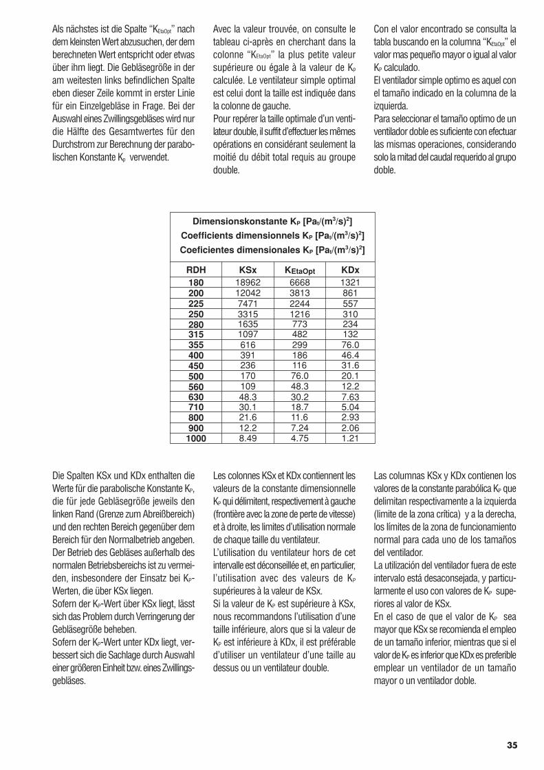
Als nächstes ist die Spalte “KEtaOpt” nachdem kleinsten Wert abzusuchen, der demberechneten Wert entspricht oder etwasüber ihm liegt. Die Gebläsegröße in deram weitesten links befindlichen Spalteeben dieser Zeile kommt in erster Liniefür ein Einzelgebläse in Frage. Bei derAuswahl eines Zwillingsgebläses wird nurdie Hälfte des Gesamtwertes für denDurchstrom zur Berechnung der parabo-lischen Konstante Kp verwendet.
Con el valor encontrado se consulta latabla buscando en la columna “KEtaOpt” elvalor mas pequeño mayor o igual al valorKP calculado.El ventilador simple optimo es aquel conel tamaño indicado en la columna de laizquierda.Para seleccionar el tamaño optimo de unventilador doble es suficiente con efectuarlas mismas operaciones, considerandosolo la mitad del caudal requerido al grupodoble.
Die Spalten KSx und KDx enthalten dieWerte für die parabolische Konstante KP,die für jede Gebläsegröße jeweils denlinken Rand (Grenze zum Abreißbereich)und den rechten Bereich gegenüber demBereich für den Normalbetrieb angeben.Der Betrieb des Gebläses außerhalb desnormalen Betriebsbereichs ist zu vermei-den, insbesondere der Einsatz bei KP-Werten, die über KSx liegen.Sofern der KP-Wert über KSx liegt, lässtsich das Problem durch Verringerung derGebläsegröße beheben.Sofern der KP-Wert unter KDx liegt, ver-bessert sich die Sachlage durch Auswahleiner größeren Einheit bzw. eines Zwillings-gebläses.
Las columnas KSx y KDx contienen losvalores de la constante parabólica KP quedelimitan respectivamente a la izquierda(limite de la zona crítica) y a la derecha,los límites de la zona de funcionamientonormal para cada uno de los tamañosdel ventilador.La utilización del ventilador fuera de esteintervalo está desaconsejada, y particu-larmente el uso con valores de KP supe-riores al valor de KSx.En el caso de que el valor de KP seamayor que KSx se recomienda el empleode un tamaño inferior, mientras que si elvalor de KP es inferior que KDx es preferibleemplear un ventilador de un tamañomayor o un ventilador doble.
Coefficients dimensionnels KP [Pat/(m3/s)2]
Coeficientes dimensionales KP [Pat/(m3/s)2]
RDH180 18962 6668 1321
KSx KEtaOpt KDx
200225250280315355400450500560630710800900
1000
12042 3813 8617471 2244 5573315 1216 3101635 773 2341097 482 132616 299 76.0391 186 46.4236 116 31.6170 76.0 20.1109 48.3 12.248.3 30.2 7.6330.1 18.7 5.0421.6 11.6 2.9312.2 7.24 2.068.49 4.75 1.21
Dimensionskonstante KP [Pat/(m3/s)2]
Avec la valeur trouvée, on consulte letableau ci-après en cherchant dans lacolonne “KEtaOpt” la plus petite valeursupérieure ou égale à la valeur de Kp
calculée. Le ventilateur simple optimalest celui dont la taille est indiquée dansla colonne de gauche.Pour repérer la taille optimale d’un venti-lateur double, il suffit d’effectuer les mêmesopérations en considérant seulement lamoitié du débit total requis au groupedouble.
Les colonnes KSx et KDx contiennent lesvaleurs de la constante dimensionnelleKP qui délimitent, respectivement à gauche(frontière avec la zone de perte de vitesse)et à droite, les limites d’utilisation normalede chaque taille du ventilateur.L’utilisation du ventilateur hors de cetintervalle est déconseillée et, en particulier,l’utilisation avec des valeurs de KP
supérieures à la valeur de KSx.Si la valeur de KP est supérieure à KSx,nous recommandons l’utilisation d’unetaille inférieure, alors que si la valeur deKP est inférieure à KDx, il est préférabled’utiliser un ventilateur d’une taille audessus ou un ventilateur double.
35
36
Raccomandazioni di impiego
Scelta del motoreCome già indicato nel paragrafo relativoalla potenza assorbita, la potenza assorbitaall’albero si ottiene sommando la potenzaal mozzo della ventola Wr , letta sul dia-gramma, alla potenza dissipata dai cusci-netti Wb , letta, in corrispondenza dellavelocità di esercizio, sulla scala verticaledella versione prescelta e collocata alladestra del diagramma.La potenza minima del motore da installaresi ottiene moltiplicando la potenza assor-bita all’albero così ottenuta, per un oppor-tuno coefficiente, dipendente dal valoredella potenza assorbita, che tiene contosia delle perdite della trasmissione che diun ragionevole margine di sicurezza, perfronteggiare piccoli cambiamenti impre-visti del punto di lavoro, o leggeri cam-biamenti della velocità di rotazione delventilatore prodotti dalla diversa velocitàdel motore impiegato o dalla necessità diusare un rapporto di trasmissione legger-mente diverso da quello teorico:
Guidelines for correct use
Motor selectionAs already explained in the “Fan power”paragraph, the fan shaft power can becalculated adding together impeller power,Wr , read on the diagram, and bearingpower at the required speed, for the se-lected fan version, Wb , found on theappropriate vertical scale at the right ofthe diagram.The minimum motor power, required todrive the fan, can be calculated multiplyingthis fan shaft power by a coefficient (fun-ction of the shaft power value) whichincludes both the belt drive power loss,and a reasonable safety margin. Thissafety margin covers any small changein the operating point or in the actual fanspeed, which may be due to a motorspeed or to a drive ratio slightly differentfrom their design values:
dove / where:
WTot è la potenza assorbitaall’alberois the fan shaft power
For RDH fans:KW = 1.25 if WTot < 0.75 kWKW = 1.15 if 0.75 kW ≤ WTot < 10 kWKW = 1.12 if WTot ≥ 10 kW
Per ventilatori RDHKW = 1.25 se WTot < 0.75 kWKW = 1.15 se 0.75 kW ≤ WTot < 10 kWKW = 1.12 se WTot ≥ 10 kW
• Ricordiamo che: 1 kW = 1.36 HP• Per motori con potenza superiore a 7.5 kW, siraccomanda l’uso di avviamenti a stella triangolo(Y/ ∆) o di dispositivi di avviamento progressivo.
• 1 kW = 1.36 HP• With motors larger than 7.5 kW the use of astar/delta (Y/∆) starter or, alternatively, of a softstarter is highly recommended.
KW è il coefficiente per la sceltadel motoreis the motor selection coefficient
37
Recommandations d’utilisation
Choix du moteurComme nous l’avons indiqué dans leparagraphe relatif à la puissance absorbée,la puissance absorbée à l’arbre est obtenueen ajoutant à la puissance au moyeu dela turbine Wr, lue sur la courbe, la puis-sance dissipée par les roulements Wb,lue, en correspondance avec la vitessed’entraînement, sur l’échelle verticale dela version prédéfinie et placée à droite dela courbe.La puissance minimum du moteur àinstaller s’obtient en multipliant la puis-sance absorbée à l’arbre ainsi obtenuepar le bon coefficient, dépendant de lavaleur de la puissance absorbée qui tientcompte des pertes de la transmission etd’une marge de sécurité raisonnable, pourdélimiter des petits changements im-prévus du point de fonctionnement oude légers changements de la vitesse derotation du ventilateur produits par lavitesse du moteur utilisé ou par la néces-sité d’utiliser un rapport de transmissionun peu différent de la théorie :
Recomendaciones de empleo
Selección del motorComo se ha explicado ya en el parágraforelativo a la potencia absorbida, la potenciaabsorbida al eje se obtiene sumando lapotencia al núcleo de la turbina Wr, leídaen el diagrama, a la potencia disipada enlos rodamientos Wb, leída, en correspon-dencia a la velocidad de ejercicio, en laescala vertical de la versión seleccionaday colocada a la derecha del diagrama.La potencia mínima a instalar del motorse obtiene multiplicando la potencia ab-sorbida en el eje así obtenida, por elcoeficiente apropiado, dependiente delvalor de la potencia absorbida, que tieneen cuenta ya sea las perdidas de la tran-smisión como un razonable margen deseguridad, para hacer frente a pequeñoscambios imprevistos del punto de trabajoo ligeros cambios en la velocidad derotación del ventilador producidos por ladiferente velocidad del motor empleadoo de la necesidad de usar una combina-ción de transmisión ligeramente diferenteal teórico:
Richtlinien für den ordnungs-gemäßen Einsatz
MotorwahlWie bereits im Abschnitt “Gebläseleistung”erläutert wurde, lässt sich die Leistungfür die Gebläsewelle durch Addition derLüfterradleistung Wr gemäß senkrechterSkala und der erforderlichen Drehzahl fürdas ausgewählte Gebläse ermitteln, dieauf der senkrechten Skala rechts auf demDiagramm abzulesen ist.Die Mindestmotorleistung für den Antriebdes Gebläses lässt sich durch Multiplizie-rung der Leistungsaufnahme der Geblä-sewelle mit einem (vom Leistungsbedarfder Welle abgeleiteten) Koeffizienten be-rechnen, der auch den Leistungsverlustfür den Riemenantrieb und einen ange-messenen Sicherheitsbereich umfasst.Dieser Sicherheitsbereich deckt allegeringfügigen Lageänderungen für denArbeitspunkt bzw. bei der tatsächlichenGebläsedrehzahl ab, die auf dem Motor-betrieb oder einem Übersetzungswert fürden Antrieb beruhen, der ggf. geringfügigvon den jeweiligen Auslegungswertenabweicht:
Hierbei ist / où / donde:
WTot die Leistungsaufnahme der Gebläsewelleest la puissance absorbée à l’arbrees la potencia absorbida en el eje
Para los ventiladores RDH:KW = 1.25 si WTot < 0.75 kWKW = 1.15 si 0.75 kW ≤ WTot < 10 kWKW = 1.12 si WTot ≥ 10 kW
Für RDH-Gebläse gilt:KW = 1.25 bei WTot < 0.75 kWKW = 1.15 bei 0.75 kW ≤ WTot < 10 kWKW = 1.12 bei WTot ≥ 10 kW
Pour les ventilateurs RDH:KW = 1.25 si WTot < 0.75 kWKW = 1.15 si 0.75 kW ≤ WTot < 10 kWKW = 1.12 si WTot ≥ 10 kW
KW der Auswahlkoeffizient für den Motorest le coefficient pour le choix du moteures el coeficiente para la selección del motor
• 1 kW = 1,36 PS• Mit Motoren über 7,5 kW ist der Einsatz einesStern-Dreieck-Anlassers (Y/ ∆) bzw. eines Softstart-Anlassers sehr zu empfehlen.
• 1 kW = 1,36 PS• Nous recommandons pour les moteurs supérieursà 7,5 KW l’utilisation d’un démarrage en étoiletriangle (Y/A) ou de dispositifs de démarragesprogressifs.
• Recordamos que: 1 kW = 1.36 HP• Para motores con potencia superior a 7.5 kW,se recomienda el uso de arranques estrella-triángulo (Y/∆) o de dispositivos de arranque progresivo.
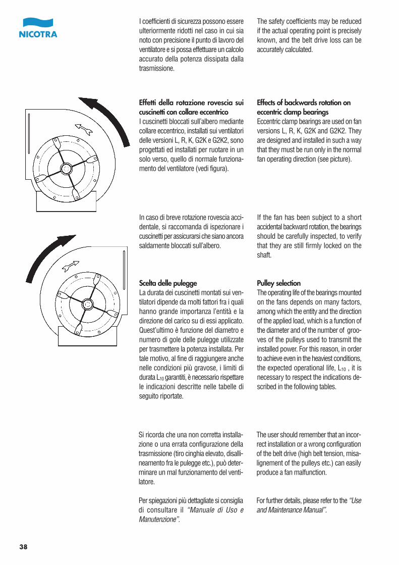
I coefficienti di sicurezza possono essereulteriormente ridotti nel caso in cui sianoto con precisione il punto di lavoro delventilatore e si possa effettuare un calcoloaccurato della potenza dissipata dallatrasmissione.
The safety coefficients may be reducedif the actual operating point is preciselyknown, and the belt drive loss can beaccurately calculated.
38
Effetti della rotazione rovescia suicuscinetti con collare eccentricoI cuscinetti bloccati sull’albero mediantecollare eccentrico, installati sui ventilatoridelle versioni L, R, K, G2K e G2K2, sonoprogettati ed installati per ruotare in unsolo verso, quello di normale funziona-mento del ventilatore (vedi figura).
Effects of backwards rotation oneccentric clamp bearingsEccentric clamp bearings are used on fanversions L, R, K, G2K and G2K2. Theyare designed and installed in such a waythat they must be run only in the normalfan operating direction (see picture).
Scelta delle puleggeLa durata dei cuscinetti montati sui ven-tilatori dipende da molti fattori fra i qualihanno grande importanza l’entità e ladirezione del carico su di essi applicato.Quest’ultimo è funzione del diametro enumero di gole delle pulegge utilizzateper trasmettere la potenza installata. Pertale motivo, al fine di raggiungere anchenelle condizioni più gravose, i limiti didurata L10 garantiti, è necessario rispettarele indicazioni descritte nelle tabelle diseguito riportate.
Pulley selectionThe operating life of the bearings mountedon the fans depends on many factors,among which the entity and the directionof the applied load, which is a function ofthe diameter and of the number of groo-ves of the pulleys used to transmit theinstalled power. For this reason, in orderto achieve even in the heaviest conditions,the expected operational life, L10 , it isnecessary to respect the indications de-scribed in the following tables.
If the fan has been subject to a shortaccidental backward rotation, the bearingsshould be carefully inspected, to verifythat they are still firmly locked on theshaft.
In caso di breve rotazione rovescia acci-dentale, si raccomanda di ispezionare icuscinetti per assicurarsi che siano ancorasaldamente bloccati sull’albero.
Si ricorda che una non corretta installa-zione o una errata configurazione dellatrasmissione (tiro cinghia elevato, disalli-neamento fra le pulegge etc.), può deter-minare un mal funzionamento del venti-latore.
Per spiegazioni più dettagliate si consigliadi consultare il “Manuale di Uso eManutenzione”.
The user should remember that an incor-rect installation or a wrong configurationof the belt drive (high belt tension, misa-lignement of the pulleys etc.) can easilyproduce a fan malfunction.
For further details, please refer to the “Useand Maintenance Manual”.
39
Die Sicherheitskoeffizienten lassen sichreduzieren, sofern der eigentliche Arbeits-punkt genau bekannt ist und die Leistungs-verluste durch den Riemenantrieb sichpräzis berechnen lassen.
Los coeficientes de seguridad pueden serreducidos en el caso en que se conozcacon precisión el punto de trabajo delventilador y se pueda efectuar un calculoajustado de la potencia disipada en latransmisión.
Auswirkungen der Rückwärtsdrehungauf Exzenter-KlemmlagerExzentrisch geklemmte Lager werden fürdie Gebläsetypen L, R, K, G2K und G2K2verwendet. Sie sind so konstruiert undeingebaut, dass sie nur in der normalenDrehrichtung des Gebläses betriebenwerden dürfen (siehe Abbildung).
Efectos de la rotación hacia atrássobre los rodamientos con anilloexcéntricoLos rodamientos bloqueados sobre el ejemediante anillo excéntrico, instalados enlos ventiladores de las versiones L, R, K,G2K y G2K2, están proyectados y insta-lados para rotar en un solo sentido, aquelde normal funcionamiento del ventilador(ver figura).
En caso de breve rotación inversa acci-dental, se recomienda de inspeccionarlos rodamientos para asegurarse queestán todavía solidamente bloqueadosen el eje.
Sofern sich ein derartiges Gebläse ausVersehen kurzzeitig rückwärts dreht, sinddie Lager genau zu prüfen, um sicherzu-stellen, dass sie noch fest auf der Wellesitzen.
Auswahl der RiemenscheibeDie Nutzungsdauer von Gebläselagernhängt von zahlreichen Faktoren ab, u.a.auch von Art und Richtung der Antriebs-leistung, die sich aus dem Durchmesserund der Anzahl von Scheibenrillen zurÜbertragung der installierten Leistungergibt. Um die voraussichtliche Nutzungs-dauer L10 auch in den schwersten Betriebs-bedingungen zu erzielen, ist es erforder-lich, entsprechend den Angaben in dennachstehenden Tabellen vorzugehen.
Selección de las poleasLa duración de los rodamientos en losventiladores depende de muchos factoresentre los cuales tiene gran importancia elvalor y la dirección de la carga aplicadasobre los mismos. Está última está enfunción del diámetro y numero de canalesde las poleas utilizadas para transmitir lapotencia instalada. Por tal motivo con elfin de conseguir, incluso en las condicionesmas gravosas, los límites de duración L10
garantizados, es necesario respetar lasindicaciones descritas en las tablas seña-ladas a continuación.
Les coefficients de sécurité peuvent êtreensuite réduits si l’on note avec précisionle point de fonctionnement du ventilateuret si l’on peut effectuer un calcul précisde la puissance dissipée par la transmis-sion.
Effets de la rotation inversée sur lesroulements à bague excentriqueLes roulements bloqués sur l’arbre parune bague excentrique, installés sur lesventilateurs des versions L, R, K, G2K, etG2K2 sont étudiés et installés pour tourneren un seul sens, le sens normal de fonc-tionnement du ventilateur (Voir figure).
En cas de brève rotation inversée de façonaccidentelle, veuillez vérifier les roulements pour s’assurer qu’ils soient encore soli-dement bloqués sur l’arbre.
Choix des pouliesLa durée de vie des roulements montéssur les ventilateurs dépend de plusieursfacteurs, parmi lesquels l’étendue et ladirection de charge appliquée sont d’unegrande importance. La charge est fonctiondu diamètre et du nombre de gorges despoulies utilisées pour transmettre la puis-sance installée. C’est pourquoi, afind’atteindre, y compris dans les conditionsles plus dures, les limites de durée L10
garanties, il est nécessaire de respecterles indications décrites dans les tableauxsuivants.
Der Anwender sollte sich stets vor Augenhalten, dass ein falscher Einbau oder dieirrtümliche Anordnung des Riementriebes(überhöhte Riemenspannung, Unwuchtder Riemenscheiben usw.) schnell zueinem Gebläseausfall führen kann.
Nähere Einzelheiten sind dem“Bedienungs- und Wartungshandbuch” zuentnehmen.
Se recuerda que una incorrecta instalacióno una configuración errónea de la tran-smisión (tensión de correas elevada,desalineación entre poleas, etc.) puededeterminar un mal funcionamiento delventilador.
Para explicaciones mas detalladas seaconseja consultar el “Manual de Uso yMantenimiento”.
Rappelons qu’une installation incorrecteou une configuration de la transmissionerronée (tension trop importante descourroies, mauvais alignement des pouliesetc…) peut entrainer un mauvais fonc-tionnement du ventilateur.
Pour de plus amples explications, veuillezconsulter le “Manuel d’utilisation et deManutention”.
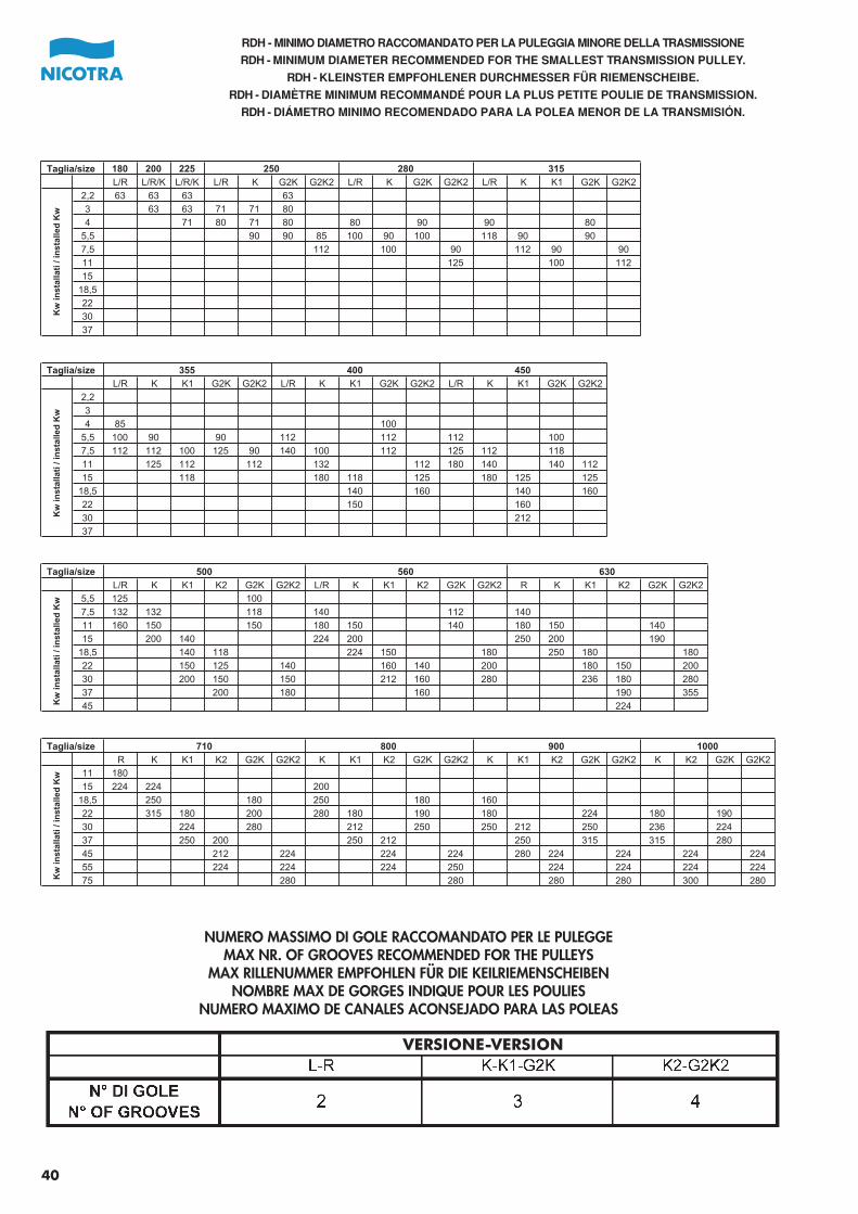
40
RDH - MINIMO DIAMETRO RACCOMANDATO PER LA PULEGGIA MINORE DELLA TRASMISSIONE
RDH - MINIMUM DIAMETER RECOMMENDED FOR THE SMALLEST TRANSMISSION PULLEY.
RDH - KLEINSTER EMPFOHLENER DURCHMESSER FÜR RIEMENSCHEIBE.
RDH - DIAMÈTRE MINIMUM RECOMMANDÉ POUR LA PLUS PETITE POULIE DE TRANSMISSION.
RDH - DIÁMETRO MINIMO RECOMENDADO PARA LA POLEA MENOR DE LA TRANSMISIÓN.
180 200 225
L/R L/R/K L/R/K L/R K G2K G2K2 L/R K G2K G2K2 L/R K K1 G2K G2K2
2,2 63 63 63 63
3 63 63 71 71 80
4 71 80 71 80 80 90 90 80
5,5 90 90 85 100 90 100 118 90 90
7,5 112 100 90 112 90 90
11 125 100 112
15
18,5
22
30
37
L/R K K1 G2K G2K2 L/R K K1 G2K G2K2 L/R K K1 G2K G2K2
2,2
3
4 85 100
5,5 100 90 90 112 112 112 100
7,5 112 112 100 125 90 140 100 112 125 112 118
11 125 112 112 132 112 180 140 140 112
15 118 180 118 125 180 125 125
18,5 140 160 140 160
22 150 160
30 212
37
L/R K K1 K2 G2K G2K2 L/R K K1 K2 G2K G2K2 R K K1 K2 G2K G2K2
5,5 125 100
7,5 132 132 118 140 112 140
11 160 150 150 180 150 140 180 150 140
15 200 140 224 200 250 200 190
18,5 140 118 224 150 180 250 180 180
22 150 125 140 160 140 200 180 150 200
30 200 150 150 212 160 280 236 180 280
37 200 180 160 190 355
45 224
R K K1 K2 G2K G2K2 K K1 K2 G2K G2K2 K K1 K2 G2K G2K2 K K2 G2K G2K2
11 180
15 224 224 200
18,5 250 180 250 180 160
22 315 180 200 280 180 190 180 224 180 190
30 224 280 212 250 250 212 250 236 224
37 250 200 250 212 250 315 315 280
45 212 224 224 224 280 224 224 224 224
55 224 224 224 250 224 224 224 224
75 280 280 280 280 300 280
Kw
inst
alla
ti /
inst
alle
d K
w
315Taglia/size
355 400
250 280
Kw
inst
alla
ti /
inst
alle
d K
w
710
450
Taglia/size 500
Kw
inst
alla
ti /
inst
alle
d K
w
560 630
Taglia/size
Kw
inst
alla
ti /
inst
alle
d K
w
800 900 1000Taglia/size
NUMERO MASSIMO DI GOLE RACCOMANDATO PER LE PULEGGEMAX NR. OF GROOVES RECOMMENDED FOR THE PULLEYS
MAX RILLENUMMER EMPFOHLEN FÜR DIE KEILRIEMENSCHEIBENNOMBRE MAX DE GORGES INDIQUE POUR LES POULIES
NUMERO MAXIMO DE CANALES ACONSEJADO PARA LAS POLEAS
VERSIONE-VERSION
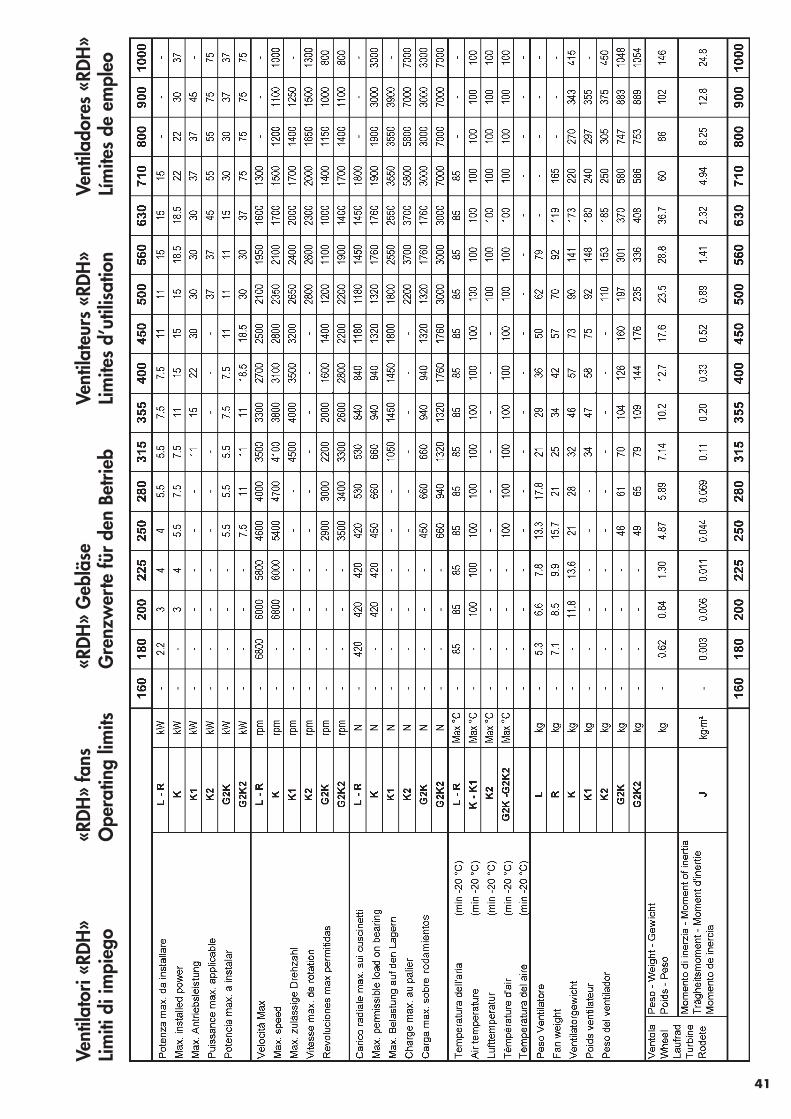
Vent
ilato
ri «R
DH»
Lim
iti d
i im
pieg
o«R
DH»
fans
Ope
ratin
g lim
its«R
DH»
Geb
läse
Gre
nzw
erte
für
den
Betri
ebVe
ntila
teur
s «R
DH»
Lim
ites
d’ut
ilisa
tion
Vent
ilado
res
«RDH
»Lí
mite
s de
em
pleo
41
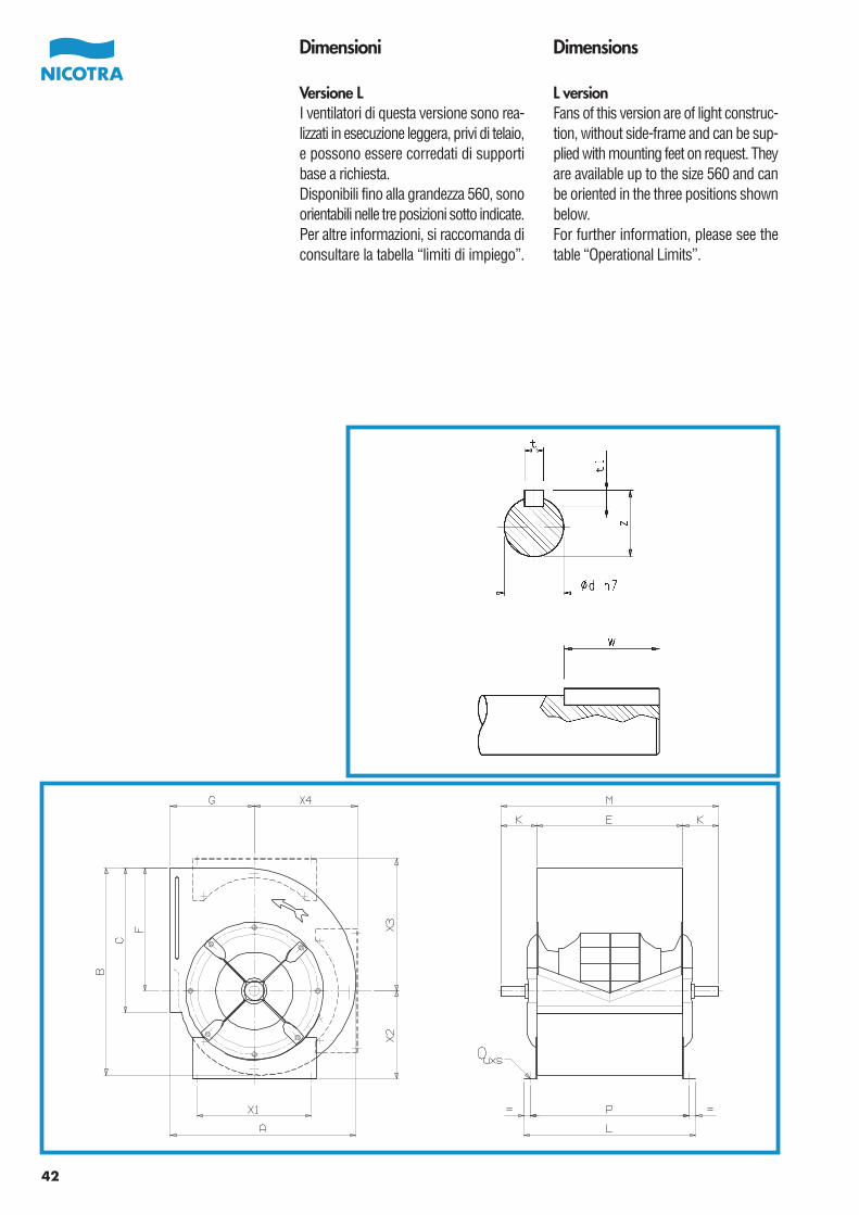
42
Dimensioni
Versione LI ventilatori di questa versione sono rea-lizzati in esecuzione leggera, privi di telaio,e possono essere corredati di supportibase a richiesta.Disponibili fino alla grandezza 560, sonoorientabili nelle tre posizioni sotto indicate.Per altre informazioni, si raccomanda diconsultare la tabella “limiti di impiego”.
Dimensions
L versionFans of this version are of light construc-tion, without side-frame and can be sup-plied with mounting feet on request. Theyare available up to the size 560 and canbe oriented in the three positions shownbelow.For further information, please see thetable “Operational Limits”.
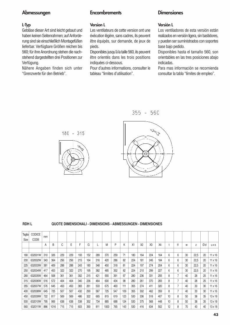
43
Encombrements
Version LLes ventilateurs de cette version ont uneéxécution légère, sans cadres, ils peuventêtre équipés, sur demande, de jeux depieds.Disponibles jusqu’à la taille 560, ils peuventêtre orientés dans les trois positionsindiquées ci-dessous.Pour d’autres informations, consulter letableau “limites d’utilisation”.
Dimensiones
Versión LLos ventiladores de esta versión estánrealizados en versión ligera, sin bastidores,y pueden ser suministrados con soportesbase bajo pedido.Disponibles hasta el tamaño 560, sonorientables en las tres posiciones abajoindicadas.Para mas información se recomiendaconsultar la tabla “límites de empleo”.
Abmessungen
L-TypGebläse dieser Art sind leicht gebaut undhaben keinen Seitenrahmen; auf Anforde-rung sind sie einschließlich Montagefüßenlieferbar. Verfügbare Größen reichen bis560; für ihre Anordnung stehen die nach-stehend dargestellten drei Positionen zurVerfügung.Nähere Angaben finden sich unter“Grenzwerte für den Betrieb”.
RDH L QUOTE DIMENSIONALI - DIMENSIONS - ABMESSUNGEN - DIMENSIONES
Taglia CODICEmm
Size CODE
A B C E F G L M P K X1 X2 X3 X4 t t1 w z Ø d u x s
180 632001W 310 326 229 229 193 152 289 370 259 71 180 164 224 164 6 6 30 22,5 20 11 x 16
200 632002W 343 364 256 256 215 164 316 420 286 82 224 181 245 184 6 6 30 22,5 20 11 x 16
225 632003W 381 409 288 288 243 180 348 450 318 81 224 197 274 204 6 6 30 22,5 20 11 x 16
250 632004W 417 453 322 322 270 195 382 485 352 82 224 210 299 227 6 6 30 22,5 20 11 x 16
280 632005W 464 508 361 361 302 215 421 555 391 97 280 236 331 255 8 7 40 28 25 11 x 16
315 632006W 516 572 404 404 340 236 464 600 434 98 280 261 370 283 8 7 40 28 25 11 x 16
355 632007W 576 645 453 453 383 261 533 675 493 111 355 274 411 320 8 7 40 33 30 11 x 16
400 632008W 645 725 507 507 432 290 587 725 547 109 355 302 462 359 8 7 40 33 30 11 x 16
450 632009W 722 817 569 569 486 322 665 815 619 123 530 336 518 407 10 8 50 38 35 13 x 18
500 632010W 795 906 638 638 538 352 734 885 688 124 530 375 568 448 10 8 50 38 35 13 x 18
560 632011W 886 1016 715 715 603 390 811 1000 765 143 530 416 634 502 12 8 70 43 40 13 x 18
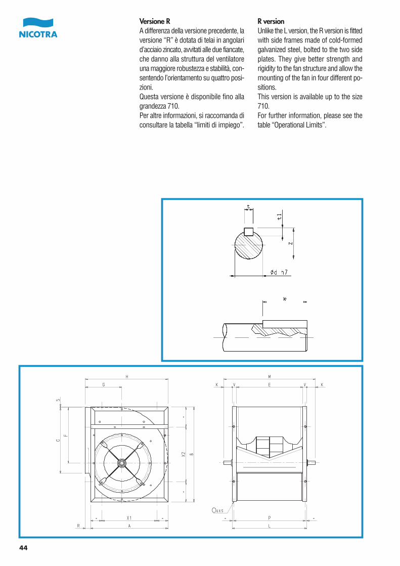
44
Versione RA differenza della versione precedente, laversione “R” è dotata di telai in angolarid’acciaio zincato, avvitati alle due fiancate,che danno alla struttura del ventilatoreuna maggiore robustezza e stabilità, con-sentendo l’orientamento su quattro posi-zioni.Questa versione è disponibile fino allagrandezza 710.Per altre informazioni, si raccomanda diconsultare la tabella “limiti di impiego”.
R versionUnlike the L version, the R version is fittedwith side frames made of cold-formedgalvanized steel, bolted to the two sideplates. They give better strength andrigidity to the fan structure and allow themounting of the fan in four different po-sitions.This version is available up to the size710.For further information, please see thetable “Operational Limits”.
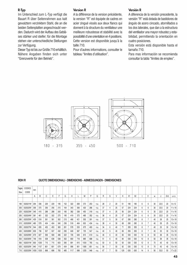
45
Version RA la différence de la version précédente,la version “R” est équipée de cadres enacier zingué vissés aux deux flancs quidonnent à la structure du ventilateur unemeilleure robustesse et stabilité avec lapossibilité d’une orientation en 4 positions.Cette version est disponible jusqu’à lataille 710.Pour d’autres informations, consulter letableau “limites d’utilisation”.
Versión RA diferencia de la versión precedente, laversión “R” está dotada de bastidores deángulo de acero cincado, atornillados alos dos laterales, que dan a la estructuradel ventilador una mayor robustez y esta-bilidad, permitiendo la orientación encuatro posiciones.Esta versión está disponible hasta eltamaño 710.Para mas información se recomiendaconsultar la tabla “límites de empleo”.
R-TypIm Unterschied zum L-Typ verfügt dieBauart R über Seitenrahmen aus kaltgewalztem verzinktem Stahl, die an diebeiden Seitenplatten angeschraubt wer-den. Dadurch wird der Aufbau des Geblä-ses stärker und steifer; für die Montagestehen vier unterschiedliche Stellungenzur Verfügung.Dieser Typ ist bis zur Größe 710 erhältlich.Nähere Angaben finden sich unter“Grenzwerte für den Betrieb”.
RDH R QUOTE DIMENSIONALI - DIMENSIONS - ABMESSUNGEN - DIMENSIONES
Taglia CODICEmm
Size CODE
A B C E F G H L M P Q R S V K X1 X2 t t1 w z Ø d u x s
180 632021W 294 336 229 229 195 152 322 269 370 253 n.a. 28 2 20 51 180 180 6 6 30 22,5 20 9 x 12
200 632022W 306 370 256 256 215 164 343 306 420 286 n.a. 37 4 25 57 224 224 6 6 30 22,5 20 11 x 16
225 632023W 345 415 288 288 243 180 382 338 450 318 n.a. 37 4 25 56 224 224 6 6 30 22,5 20 11 x 16
250 632024W 381 461 322 322 270 195 419 372 485 352 n.a. 38 4 25 57 224 224 6 6 30 22,5 20 11 x 16
280 632025W 429 518 361 361 302 215 466 421 555 391 n.a. 37 5 30 67 280 280 8 7 40 28 25 13 x 18
315 632026W 480 578 404 404 340 236 518 464 600 434 n.a. 38 4 30 68 280 280 8 7 40 28 25 13 x 18
355 632027W 544 655 453 453 383 261 578 533 675 493 n.a. 34 6 40 71 355 355 8 7 40 33 30 13 x 18
400 632028W 609 736 507 507 432 290 649 587 725 547 n.a. 40 5 40 69 355 355 8 7 40 33 30 13 x 18
450 632029W 679 827 569 569 486 322 726 649 815 619 n.a. 46 6 40 83 530 530 10 8 50 38 35 13 x 18
500 632030W 748 918 638 638 538 352 800 718 885 688 n.a. 51 6 40 84 530 530 10 8 50 38 35 13 x 18
560 632031W 830 1030 715 715 603 390 891 815 1000 765 n.a. 50 8 50 93 530 530 12 8 70 43 40 13 x 18
630 632032W 940 1157 801 801 679 434 996 901 1085 851 n.a. 56 7 50 92 530 530 12 8 70 43 40 13 x 18
710 632033W 1050 1303 898 898 765 485 1117 998 1255 948 n.a. 67 7 50 129 630 630 14 9 90 53,5 50 17 x 22
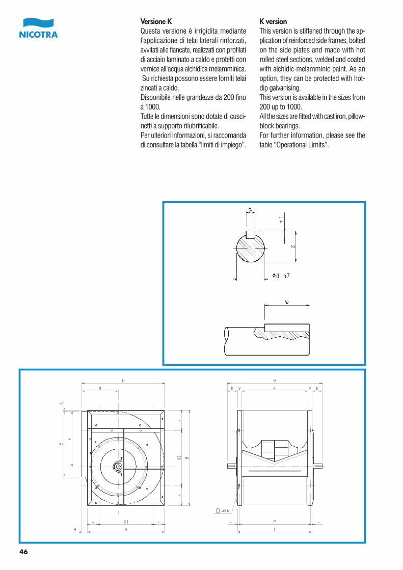
46
Versione KQuesta versione è irrigidita mediantel’applicazione di telai laterali rinforzati,avvitati alle fiancate, realizzati con profilatidi acciaio laminato a caldo e protetti convernice all'acqua alchidica melamminica. Su richiesta possono essere forniti telaizincati a caldo.Disponibile nelle grandezze da 200 finoa 1000.Tutte le dimensioni sono dotate di cusci-netti a supporto rilubrificabile.Per ulteriori informazioni, si raccomandadi consultare la tabella “limiti di impiego”.
K versionThis version is stiffened through the ap-plication of reinforced side frames, boltedon the side plates and made with hotrolled steel sections, welded and coatedwith alchidic-melamminic paint. As anoption, they can be protected with hot-dip galvanising.This version is available in the sizes from200 up to 1000.All the sizes are fitted with cast iron, pillow-block bearings.For further information, please see thetable “Operational Limits”.
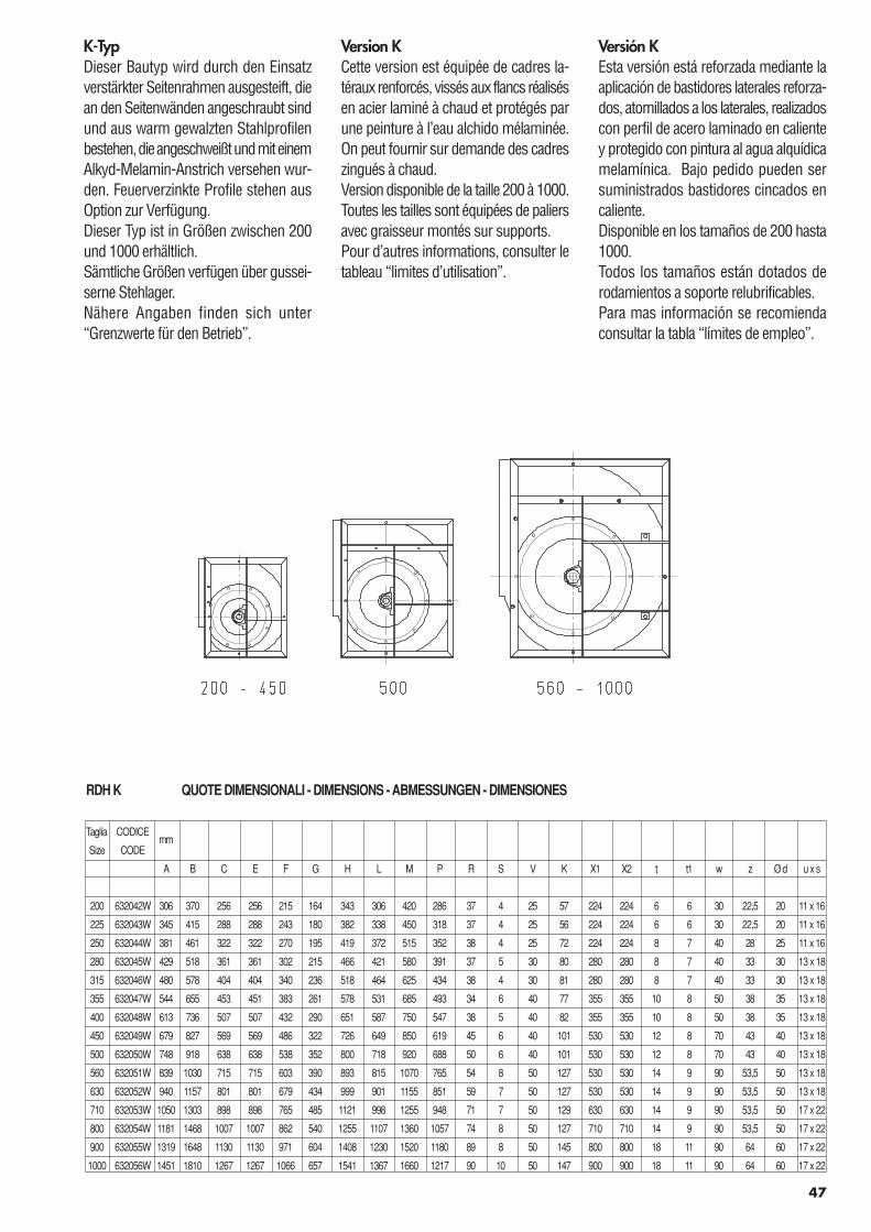
47
Version KCette version est équipée de cadres la-téraux renforcés, vissés aux flancs réalisésen acier laminé à chaud et protégés parune peinture à l’eau alchido mélaminée.On peut fournir sur demande des cadreszingués à chaud.Version disponible de la taille 200 à 1000.Toutes les tailles sont équipées de paliersavec graisseur montés sur supports.Pour d’autres informations, consulter letableau “limites d’utilisation”.
Versión KEsta versión está reforzada mediante laaplicación de bastidores laterales reforza-dos, atornillados a los laterales, realizadoscon perfil de acero laminado en calientey protegido con pintura al agua alquídicamelamínica. Bajo pedido pueden sersuministrados bastidores cincados encaliente.Disponible en los tamaños de 200 hasta1000.Todos los tamaños están dotados derodamientos a soporte relubrificables.Para mas información se recomiendaconsultar la tabla “límites de empleo”.
K-TypDieser Bautyp wird durch den Einsatzverstärkter Seitenrahmen ausgesteift, diean den Seitenwänden angeschraubt sindund aus warm gewalzten Stahlprofilenbestehen, die angeschweißt und mit einemAlkyd-Melamin-Anstrich versehen wur-den. Feuerverzinkte Profile stehen ausOption zur Verfügung.Dieser Typ ist in Größen zwischen 200und 1000 erhältlich.Sämtliche Größen verfügen über gussei-serne Stehlager.Nähere Angaben finden sich unter“Grenzwerte für den Betrieb”.
RDH K QUOTE DIMENSIONALI - DIMENSIONS - ABMESSUNGEN - DIMENSIONES
Taglia CODICEmm
Size CODE
A B C E F G H L M P R S V K X1 X2 t t1 w z Ø d u x s
200 632042W 306 370 256 256 215 164 343 306 420 286 37 4 25 57 224 224 6 6 30 22,5 20 11 x 16
225 632043W 345 415 288 288 243 180 382 338 450 318 37 4 25 56 224 224 6 6 30 22,5 20 11 x 16
250 632044W 381 461 322 322 270 195 419 372 515 352 38 4 25 72 224 224 8 7 40 28 25 11 x 16
280 632045W 429 518 361 361 302 215 466 421 580 391 37 5 30 80 280 280 8 7 40 33 30 13 x 18
315 632046W 480 578 404 404 340 236 518 464 625 434 38 4 30 81 280 280 8 7 40 33 30 13 x 18
355 632047W 544 655 453 451 383 261 578 531 685 493 34 6 40 77 355 355 10 8 50 38 35 13 x 18
400 632048W 613 736 507 507 432 290 651 587 750 547 38 5 40 82 355 355 10 8 50 38 35 13 x 18
450 632049W 679 827 569 569 486 322 726 649 850 619 45 6 40 101 530 530 12 8 70 43 40 13 x 18
500 632050W 748 918 638 638 538 352 800 718 920 688 50 6 40 101 530 530 12 8 70 43 40 13 x 18
560 632051W 839 1030 715 715 603 390 893 815 1070 765 54 8 50 127 530 530 14 9 90 53,5 50 13 x 18
630 632052W 940 1157 801 801 679 434 999 901 1155 851 59 7 50 127 530 530 14 9 90 53,5 50 13 x 18
710 632053W 1050 1303 898 898 765 485 1121 998 1255 948 71 7 50 129 630 630 14 9 90 53,5 50 17 x 22
800 632054W 1181 1468 1007 1007 862 540 1255 1107 1360 1057 74 8 50 127 710 710 14 9 90 53,5 50 17 x 22
900 632055W 1319 1648 1130 1130 971 604 1408 1230 1520 1180 89 8 50 145 800 800 18 11 90 64 60 17 x 22
1000 632056W 1451 1810 1267 1267 1066 657 1541 1367 1660 1217 90 10 50 147 900 900 18 11 90 64 60 17 x 22
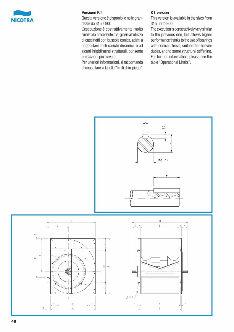
48
Versione K1Questa versione è disponibile nelle gran-dezze da 315 a 900.L’esecuzione è costruttivamente moltosimile alla precedente ma, grazie all’utilizzodi cuscinetti con bussola conica, adatti asopportare forti carichi dinamici, e adalcuni irrigidimenti strutturali, consenteprestazioni più elevate.Per ulteriori informazioni, si raccomandadi consultare la tabella “limiti di impiego”.
K1 versionThis version is available in the sizes from315 up to 900.The execution is constructively very similarto the previous one, but allows higherperformance thanks to the use of bearingswith conical sleeve, suitable for heavierduties, and to some structural stiffening.For further information, please see thetable “Operational Limits”.
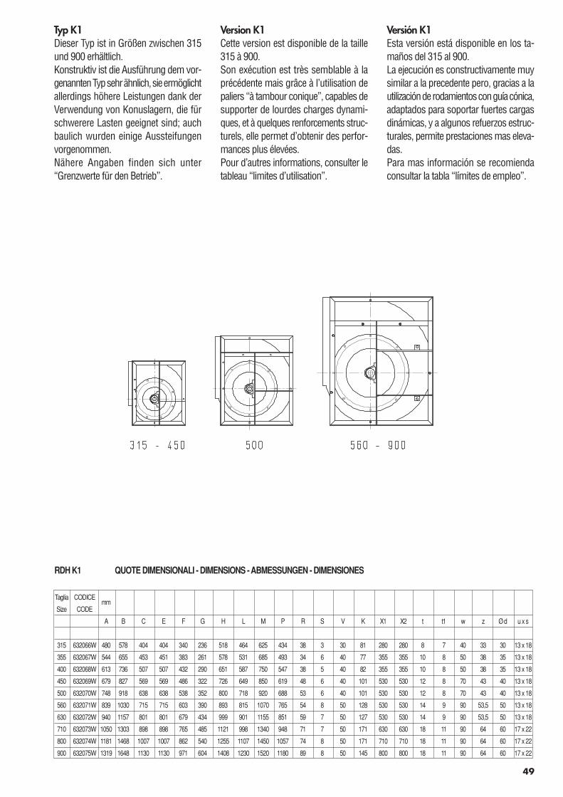
49
Version K1Cette version est disponible de la taille315 à 900.Son exécution est très semblable à laprécédente mais grâce à l’utilisation depaliers “à tambour conique”, capables desupporter de lourdes charges dynami-ques, et à quelques renforcements struc-turels, elle permet d’obtenir des perfor-mances plus élevées.Pour d’autres informations, consulter letableau “limites d’utilisation”.
Versión K1Esta versión está disponible en los ta-maños del 315 al 900.La ejecución es constructivamente muysimilar a la precedente pero, gracias a lautilización de rodamientos con guía cónica,adaptados para soportar fuertes cargasdinámicas, y a algunos refuerzos estruc-turales, permite prestaciones mas eleva-das.Para mas información se recomiendaconsultar la tabla “límites de empleo”.
Typ K1Dieser Typ ist in Größen zwischen 315und 900 erhältlich.Konstruktiv ist die Ausführung dem vor-genannten Typ sehr ähnlich, sie ermöglichtallerdings höhere Leistungen dank derVerwendung von Konuslagern, die fürschwerere Lasten geeignet sind; auchbaulich wurden einige Aussteifungenvorgenommen.Nähere Angaben finden sich unter“Grenzwerte für den Betrieb”.
RDH K1 QUOTE DIMENSIONALI - DIMENSIONS - ABMESSUNGEN - DIMENSIONES
Taglia CODICEmm
Size CODE
A B C E F G H L M P R S V K X1 X2 t t1 w z Ø d u x s
315 632066W 480 578 404 404 340 236 518 464 625 434 38 3 30 81 280 280 8 7 40 33 30 13 x 18
355 632067W 544 655 453 451 383 261 578 531 685 493 34 6 40 77 355 355 10 8 50 38 35 13 x 18
400 632068W 613 736 507 507 432 290 651 587 750 547 38 5 40 82 355 355 10 8 50 38 35 13 x 18
450 632069W 679 827 569 569 486 322 726 649 850 619 48 6 40 101 530 530 12 8 70 43 40 13 x 18
500 632070W 748 918 638 638 538 352 800 718 920 688 53 6 40 101 530 530 12 8 70 43 40 13 x 18
560 632071W 839 1030 715 715 603 390 893 815 1070 765 54 8 50 128 530 530 14 9 90 53,5 50 13 x 18
630 632072W 940 1157 801 801 679 434 999 901 1155 851 59 7 50 127 530 530 14 9 90 53,5 50 13 x 18
710 632073W 1050 1303 898 898 765 485 1121 998 1340 948 71 7 50 171 630 630 18 11 90 64 60 17 x 22
800 632074W 1181 1468 1007 1007 862 540 1255 1107 1450 1057 74 8 50 171 710 710 18 11 90 64 60 17 x 22
900 632075W 1319 1648 1130 1130 971 604 1408 1230 1520 1180 89 8 50 145 800 800 18 11 90 64 60 17 x 22
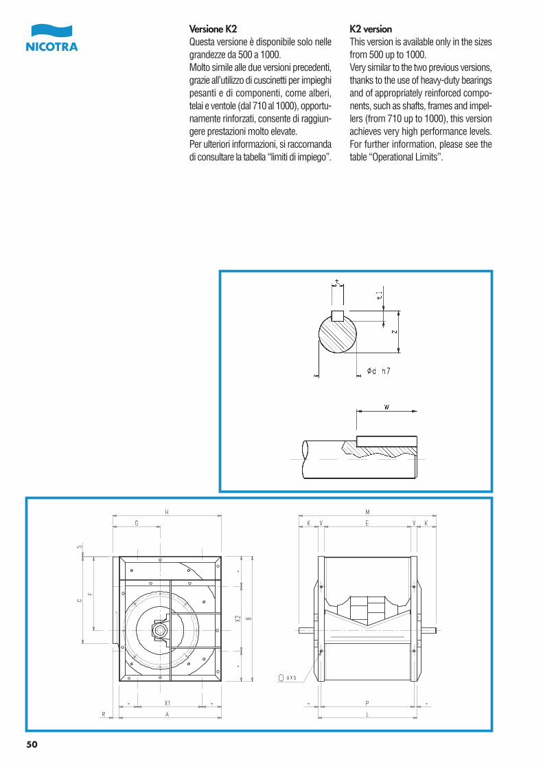
50
Versione K2Questa versione è disponibile solo nellegrandezze da 500 a 1000.Molto simile alle due versioni precedenti,grazie all’utilizzo di cuscinetti per impieghipesanti e di componenti, come alberi,telai e ventole (dal 710 al 1000), opportu-namente rinforzati, consente di raggiun-gere prestazioni molto elevate.Per ulteriori informazioni, si raccomandadi consultare la tabella “limiti di impiego”.
K2 versionThis version is available only in the sizesfrom 500 up to 1000.Very similar to the two previous versions,thanks to the use of heavy-duty bearingsand of appropriately reinforced compo-nents, such as shafts, frames and impel-lers (from 710 up to 1000), this versionachieves very high performance levels.For further information, please see thetable “Operational Limits”.
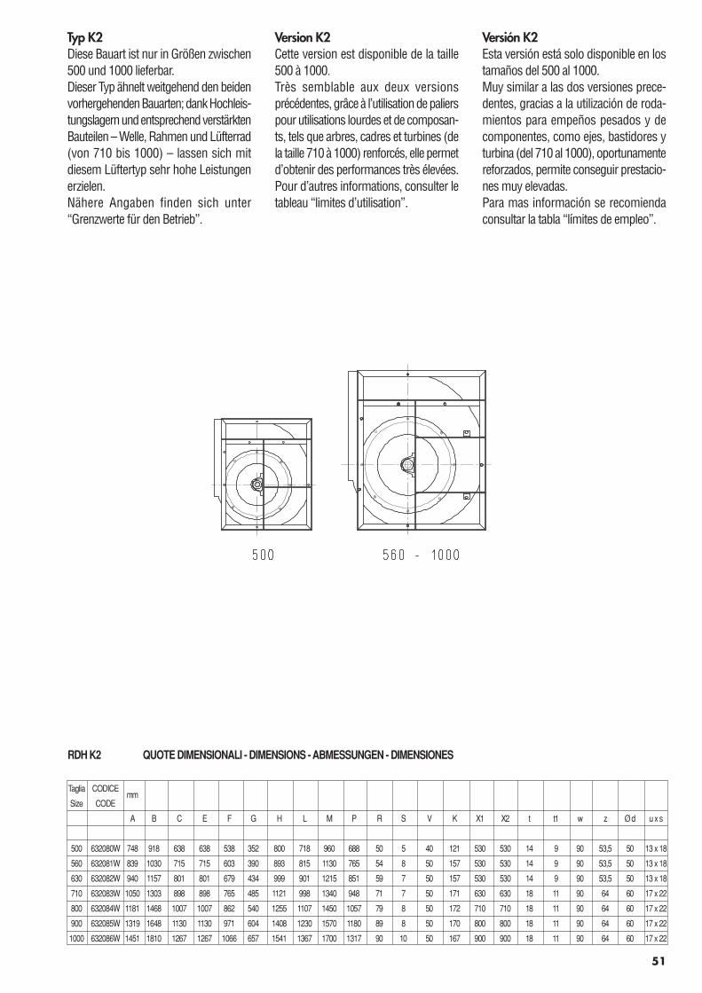
Version K2Cette version est disponible de la taille500 à 1000.Très semblable aux deux versionsprécédentes, grâce à l’utilisation de palierspour utilisations lourdes et de composan-ts, tels que arbres, cadres et turbines (dela taille 710 à 1000) renforcés, elle permetd’obtenir des performances très élevées.Pour d’autres informations, consulter letableau “limites d’utilisation”.
Versión K2Esta versión está solo disponible en lostamaños del 500 al 1000.Muy similar a las dos versiones prece-dentes, gracias a la utilización de roda-mientos para empeños pesados y decomponentes, como ejes, bastidores yturbina (del 710 al 1000), oportunamentereforzados, permite conseguir prestacio-nes muy elevadas.Para mas información se recomiendaconsultar la tabla “límites de empleo”.
Typ K2Diese Bauart ist nur in Größen zwischen500 und 1000 lieferbar.Dieser Typ ähnelt weitgehend den beidenvorhergehenden Bauarten; dank Hochleis-tungslagern und entsprechend verstärktenBauteilen – Welle, Rahmen und Lüfterrad(von 710 bis 1000) – lassen sich mitdiesem Lüftertyp sehr hohe Leistungenerzielen.Nähere Angaben finden sich unter“Grenzwerte für den Betrieb”.
51
RDH K2 QUOTE DIMENSIONALI - DIMENSIONS - ABMESSUNGEN - DIMENSIONES
Taglia CODICEmm
Size CODE
A B C E F G H L M P R S V K X1 X2 t t1 w z Ø d u x s
500 632080W 748 918 638 638 538 352 800 718 960 688 50 5 40 121 530 530 14 9 90 53,5 50 13 x 18
560 632081W 839 1030 715 715 603 390 893 815 1130 765 54 8 50 157 530 530 14 9 90 53,5 50 13 x 18
630 632082W 940 1157 801 801 679 434 999 901 1215 851 59 7 50 157 530 530 14 9 90 53,5 50 13 x 18
710 632083W 1050 1303 898 898 765 485 1121 998 1340 948 71 7 50 171 630 630 18 11 90 64 60 17 x 22
800 632084W 1181 1468 1007 1007 862 540 1255 1107 1450 1057 79 8 50 172 710 710 18 11 90 64 60 17 x 22
900 632085W 1319 1648 1130 1130 971 604 1408 1230 1570 1180 89 8 50 170 800 800 18 11 90 64 60 17 x 22
1000 632086W 1451 1810 1267 1267 1066 657 1541 1367 1700 1317 90 10 50 167 900 900 18 11 90 64 60 17 x 22
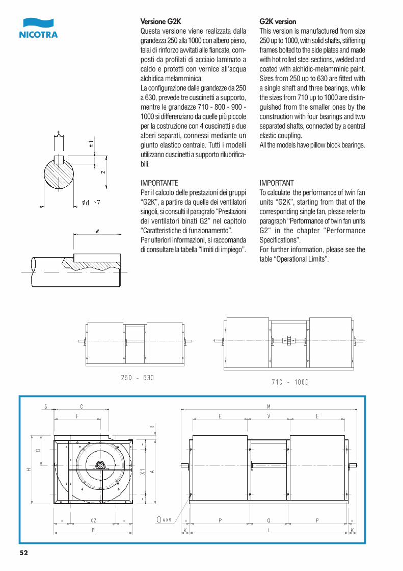
52
Versione G2KQuesta versione viene realizzata dallagrandezza 250 alla 1000 con albero pieno,telai di rinforzo avvitati alle fiancate, com-posti da profilati di acciaio laminato acaldo e protetti con vernice all'acquaalchidica melamminica.La configurazione dalle grandezze da 250a 630, prevede tre cuscinetti a supporto,mentre le grandezze 710 - 800 - 900 -1000 si differenziano da quelle più piccoleper la costruzione con 4 cuscinetti e duealberi separati, connessi mediante ungiunto elastico centrale. Tutti i modelliutilizzano cuscinetti a supporto rilubrifica-bili.
IMPORTANTEPer il calcolo delle prestazioni dei gruppi“G2K”, a partire da quelle dei ventilatorisingoli, si consulti il paragrafo “Prestazionidei ventilatori binati G2” nel capitolo“Caratteristiche di funzionamento”.Per ulteriori informazioni, si raccomandadi consultare la tabella “limiti di impiego”.
G2K versionThis version is manufactured from size250 up to 1000, with solid shafts, stiffeningframes bolted to the side plates and madewith hot rolled steel sections, welded andcoated with alchidic-melamminic paint.Sizes from 250 up to 630 are fitted witha single shaft and three bearings, whilethe sizes from 710 up to 1000 are distin-guished from the smaller ones by theconstruction with four bearings and twoseparated shafts, connected by a centralelastic coupling.All the models have pillow block bearings.
IMPORTANTTo calculate the performance of twin fanunits “G2K”, starting from that of thecorresponding single fan, please refer toparagraph “Performance of twin fan unitsG2“ in the chapter “PerformanceSpecifications”.For further information, please see thetable “Operational Limits”.
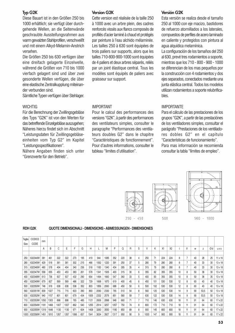
53
Version G2KCette version est réalisée de la taille 250à 1000 avec un arbre plein, des cadresrenforcés vissés aux flancs composés deprofilés d’acier laminé à chaud et protégéspar peinture à l’eau alchido mélaminée.Les tailles 250 à 630 sont équipées detrois paliers sur supports, alors que lestailles 710-800-900-1000 sont équipéesde 4 paliers et deux arbres séparés, reliéspar un joint élastique central. Tous lesmodèles sont équipés de paliers avecgraisseur sur support.
IMPORTANTPour le calcul des performances desversions “G2K”, à partir des performancesdes ventilateurs simples, consulter leparagraphe “Performances des ventila-teurs doubles G2” dans le chapitre“Caractéristiques de fonctionnement”.Pour d’autres informations, consulter letableau “limites d’utilisation”.
Versión G2KEsta versión se realiza desde el tamaño250 al 1000 con eje macizo, bastidoresde refuerzo atornillados a los laterales,compuestos de perfiles de acero laminadoen caliente y protegidos con pintura alagua alquídica melamínica.La configuración de los tamaños del 250al 630, prevé tres rodamientos a soporte,mientras que los 710 - 800 - 900 - 1000se diferencian de los mas pequeños porla construcción con 4 rodamientos y dosejes separados, conectados mediante unajunta elástica central. Todos los modelosutilizan rodamientos a soporte relubrifica-bles.
IMPORTANTEPara el cálculo de las prestaciones de losgrupos “G2K”, a partir de las prestaciónesde los ventiladores simples, consultar elparágrafo “Prestaciones de los ventilado-res dobles G2” en el capítulo“Características de funcionamiento”.Para mas información se recomiendaconsultar la tabla “límites de empleo”.
Typ G2KDiese Bauart ist in den Größen 250 bis1000 erhältlich; sie verfügt über durch-gehende Wellen, an die Seitenwändegeschraubte Aussteifungsrahmen auswarm gewalzten Stahlprofilen, verschweißtund mit einem Alkyd-Melamin-Anstrichversehen.Die Größen 250 bis 630 verfügen übereine dreifach gelagerte Einzelwelle,während die Größen von 710 bis 1000vierfach gelagert sind und über zweigesonderte Wellen verfügen, die übereine elastische Zentralkupplung miteinan-der verbunden sind.Sämtliche Typen verfügen über Stehlager.
WICHTIGFür die Berechnung der Zwillingsgebläsedes Typs “G2K” ist von den Werten fürdas betreffende Einzelgebläse auszugehen;Näheres hierzu findet sich im Abschnitt“Leistungsdaten für Zwillingsgebläse-einheiten vom Typ G2” im Kapitel“Leistungsspezifikationen”.Nähere Angaben finden sich unter“Grenzwerte für den Betrieb”.
RDH G2K QUOTE DIMENSIONALI - DIMENSIONS - ABMESSUNGEN - DIMENSIONES
Taglia CODICEmm
Size CODE
A B C E F G H L M P Q R S V K X1 X2 t t1 w z Ø d u x s
250 632344W 381 461 322 322 270 195 419 944 1085 352 220 38 4 250 71 224 224 8 7 40 28 25 11 x 16
280 632345W 429 518 361 361 302 215 466 1062 1220 391 250 37 5 280 79 280 280 8 7 40 33 30 13 x 18
315 632346W 480 578 404 404 340 236 518 1183 1340 434 285 35 4 315 79 280 280 8 7 40 33 30 13 x 18
355 632347W 558 655 453 453 383 261 578 1341 1505 493 315 30 6 355 82 355 355 10 8 50 38 30 13 x 18
400 632348W 613 736 507 507 432 290 654 1494 1660 547 360 33 5 400 83 355 355 10 8 50 38 35 13 x 18
450 632349W 679 827 569 569 486 322 729 1668 1870 619 400 45 6 450 101 530 530 12 8 60 43 40 13 x 18
500 632350W 748 918 638 638 538 352 803 1856 2060 688 450 50 6 500 102 530 530 12 8 60 43 40 13 x 18
560 632351W 839 1027 715 715 603 390 893 2090 2330 765 510 54 8 560 120 530 530 14 9 90 53,5 50 13 x 18
630 632352W 940 1157 801 801 679 434 1005 2332 2576 851 580 59 7 630 122 530 530 14 9 90 53,5 50 13 x 18
710 632353W 1050 1303 898 898 765 485 1121 2606 2898 948 660 71 7 710 146 630 630 18 11 91 64 60 17 x 22
800 632354W 1181 1468 1007 1007 862 540 1255 2914 3257 1057 750 74 8 800 172 710 710 18 11 91 64 60 17 x 22
900 632355W 1319 1648 1130 1130 971 604 1408 3260 3550 1180 850 89 8 900 145 800 800 18 11 91 64 60 17 x 22
1000 632356W 1451 1810 1267 1267 1066 657 1541 3634 3927 1317 950 90 9 1000 147 900 900 18 11 91 64 60 17 x 22
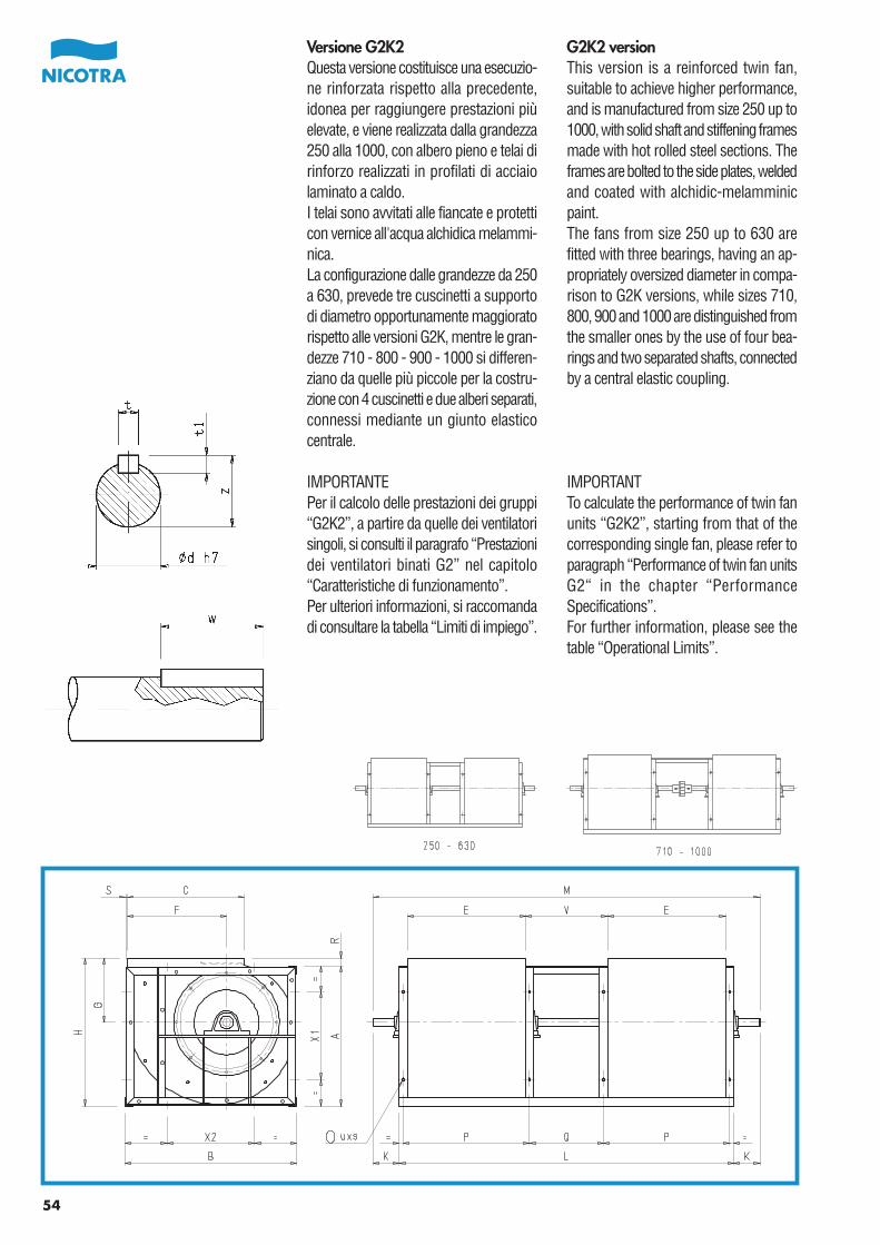
54
Versione G2K2Questa versione costituisce una esecuzio-ne rinforzata rispetto alla precedente,idonea per raggiungere prestazioni piùelevate, e viene realizzata dalla grandezza250 alla 1000, con albero pieno e telai dirinforzo realizzati in profilati di acciaiolaminato a caldo.I telai sono avvitati alle fiancate e protetticon vernice all'acqua alchidica melammi-nica.La configurazione dalle grandezze da 250a 630, prevede tre cuscinetti a supportodi diametro opportunamente maggioratorispetto alle versioni G2K, mentre le gran-dezze 710 - 800 - 900 - 1000 si differen-ziano da quelle più piccole per la costru-zione con 4 cuscinetti e due alberi separati,connessi mediante un giunto elasticocentrale.
IMPORTANTEPer il calcolo delle prestazioni dei gruppi“G2K2”, a partire da quelle dei ventilatorisingoli, si consulti il paragrafo “Prestazionidei ventilatori binati G2” nel capitolo“Caratteristiche di funzionamento”.Per ulteriori informazioni, si raccomandadi consultare la tabella “Limiti di impiego”.
G2K2 versionThis version is a reinforced twin fan,suitable to achieve higher performance,and is manufactured from size 250 up to1000, with solid shaft and stiffening framesmade with hot rolled steel sections. Theframes are bolted to the side plates, weldedand coated with alchidic-melamminicpaint.The fans from size 250 up to 630 arefitted with three bearings, having an ap-propriately oversized diameter in compa-rison to G2K versions, while sizes 710,800, 900 and 1000 are distinguished fromthe smaller ones by the use of four bea-rings and two separated shafts, connectedby a central elastic coupling.
IMPORTANTTo calculate the performance of twin fanunits “G2K2”, starting from that of thecorresponding single fan, please refer toparagraph “Performance of twin fan unitsG2“ in the chapter “PerformanceSpecifications”.For further information, please see thetable “Operational Limits”.
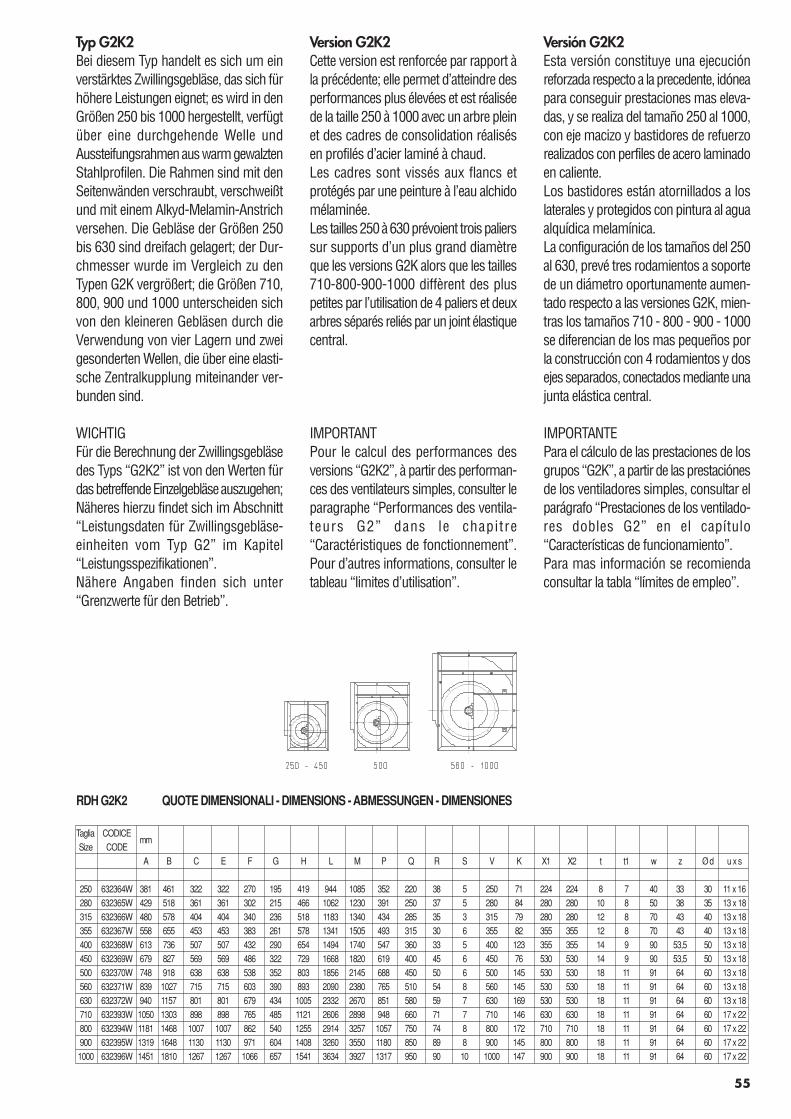
55
Version G2K2Cette version est renforcée par rapport àla précédente; elle permet d’atteindre desperformances plus élevées et est réaliséede la taille 250 à 1000 avec un arbre pleinet des cadres de consolidation réalisésen profilés d’acier laminé à chaud.Les cadres sont vissés aux flancs etprotégés par une peinture à l’eau alchidomélaminée.Les tailles 250 à 630 prévoient trois palierssur supports d’un plus grand diamètreque les versions G2K alors que les tailles710-800-900-1000 diffèrent des pluspetites par l’utilisation de 4 paliers et deuxarbres séparés reliés par un joint élastiquecentral.
IMPORTANTPour le calcul des performances desversions “G2K2”, à partir des performan-ces des ventilateurs simples, consulter leparagraphe “Performances des ventila-teurs G2” dans le chapitre“Caractéristiques de fonctionnement”.Pour d’autres informations, consulter letableau “limites d’utilisation”.
Versión G2K2Esta versión constituye una ejecuciónreforzada respecto a la precedente, idóneapara conseguir prestaciones mas eleva-das, y se realiza del tamaño 250 al 1000,con eje macizo y bastidores de refuerzorealizados con perfiles de acero laminadoen caliente.Los bastidores están atornillados a loslaterales y protegidos con pintura al aguaalquídica melamínica.La configuración de los tamaños del 250al 630, prevé tres rodamientos a soportede un diámetro oportunamente aumen-tado respecto a las versiones G2K, mien-tras los tamaños 710 - 800 - 900 - 1000se diferencian de los mas pequeños porla construcción con 4 rodamientos y dosejes separados, conectados mediante unajunta elástica central.
IMPORTANTEPara el cálculo de las prestaciones de losgrupos “G2K”, a partir de las prestaciónesde los ventiladores simples, consultar elparágrafo “Prestaciones de los ventilado-res dobles G2” en el capítulo“Características de funcionamiento”.Para mas información se recomiendaconsultar la tabla “límites de empleo”.
Typ G2K2Bei diesem Typ handelt es sich um einverstärktes Zwillingsgebläse, das sich fürhöhere Leistungen eignet; es wird in denGrößen 250 bis 1000 hergestellt, verfügtüber eine durchgehende Welle undAussteifungsrahmen aus warm gewalztenStahlprofilen. Die Rahmen sind mit denSeitenwänden verschraubt, verschweißtund mit einem Alkyd-Melamin-Anstrichversehen. Die Gebläse der Größen 250bis 630 sind dreifach gelagert; der Dur-chmesser wurde im Vergleich zu denTypen G2K vergrößert; die Größen 710,800, 900 und 1000 unterscheiden sichvon den kleineren Gebläsen durch dieVerwendung von vier Lagern und zweigesonderten Wellen, die über eine elasti-sche Zentralkupplung miteinander ver-bunden sind.
WICHTIGFür die Berechnung der Zwillingsgebläsedes Typs “G2K2” ist von den Werten fürdas betreffende Einzelgebläse auszugehen;Näheres hierzu findet sich im Abschnitt“Leistungsdaten für Zwillingsgebläse-einheiten vom Typ G2” im Kapitel“Leistungsspezifikationen”.Nähere Angaben finden sich unter“Grenzwerte für den Betrieb”.
RDH G2K2 QUOTE DIMENSIONALI - DIMENSIONS - ABMESSUNGEN - DIMENSIONES
Taglia CODICEmm
Size CODEA B C E F G H L M P Q R S V K X1 X2 t t1 w z Ø d u x s
250 632364W 381 461 322 322 270 195 419 944 1085 352 220 38 5 250 71 224 224 8 7 40 33 30 11 x 16280 632365W 429 518 361 361 302 215 466 1062 1230 391 250 37 5 280 84 280 280 10 8 50 38 35 13 x 18315 632366W 480 578 404 404 340 236 518 1183 1340 434 285 35 3 315 79 280 280 12 8 70 43 40 13 x 18355 632367W 558 655 453 453 383 261 578 1341 1505 493 315 30 6 355 82 355 355 12 8 70 43 40 13 x 18400 632368W 613 736 507 507 432 290 654 1494 1740 547 360 33 5 400 123 355 355 14 9 90 53,5 50 13 x 18450 632369W 679 827 569 569 486 322 729 1668 1820 619 400 45 6 450 76 530 530 14 9 90 53,5 50 13 x 18500 632370W 748 918 638 638 538 352 803 1856 2145 688 450 50 6 500 145 530 530 18 11 91 64 60 13 x 18560 632371W 839 1027 715 715 603 390 893 2090 2380 765 510 54 8 560 145 530 530 18 11 91 64 60 13 x 18630 632372W 940 1157 801 801 679 434 1005 2332 2670 851 580 59 7 630 169 530 530 18 11 91 64 60 13 x 18710 632393W 1050 1303 898 898 765 485 1121 2606 2898 948 660 71 7 710 146 630 630 18 11 91 64 60 17 x 22800 632394W 1181 1468 1007 1007 862 540 1255 2914 3257 1057 750 74 8 800 172 710 710 18 11 91 64 60 17 x 22900 632395W 1319 1648 1130 1130 971 604 1408 3260 3550 1180 850 89 8 900 145 800 800 18 11 91 64 60 17 x 221000 632396W 1451 1810 1267 1267 1066 657 1541 3634 3927 1317 950 90 10 1000 147 900 900 18 11 91 64 60 17 x 22
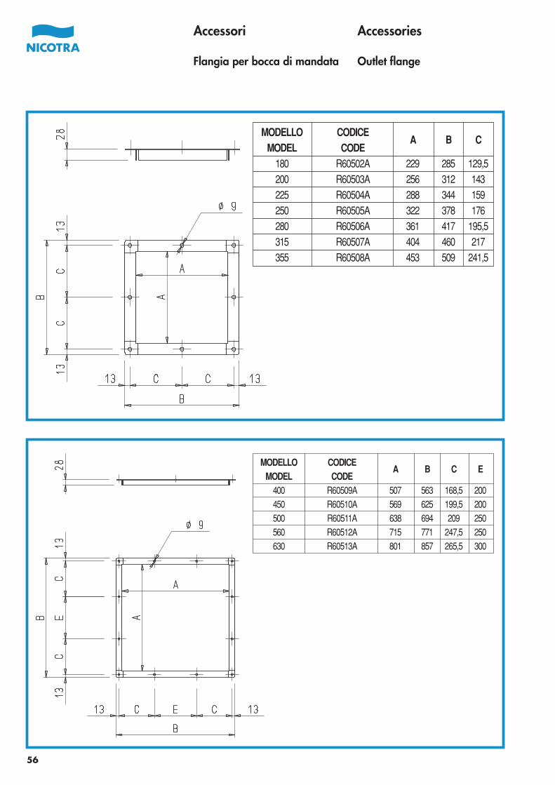
56
Accessori
Flangia per bocca di mandata
Accessories
Outlet flange
MODELLO CODICEA B C
MODEL CODE180 R60502A 229 285 129,5200 R60503A 256 312 143225 R60504A 288 344 159250 R60505A 322 378 176280 R60506A 361 417 195,5315 R60507A 404 460 217355 R60508A 453 509 241,5
MODELLO CODICEA B C E
MODEL CODE400 R60509A 507 563 168,5 200450 R60510A 569 625 199,5 200500 R60511A 638 694 209 250560 R60512A 715 771 247,5 250630 R60513A 801 857 265,5 300
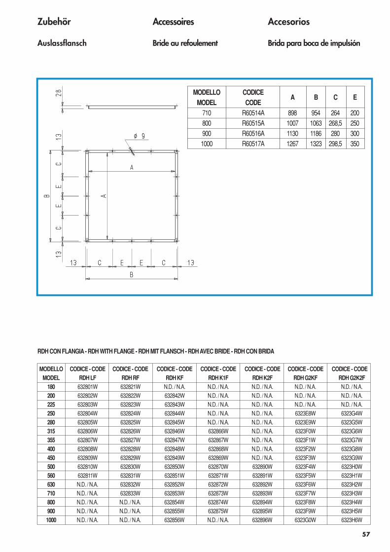
57
Accessoires
Bride au refoulement
Accesorios
Brida para boca de impulsión
Zubehör
Auslassflansch
MODELLO CODICEA B C E
MODEL CODE710 R60514A 898 954 264 200800 R60515A 1007 1063 268,5 250900 R60516A 1130 1186 280 3001000 R60517A 1267 1323 298,5 350
MODELLO CODICE - CODE CODICE - CODE CODICE - CODE CODICE - CODE CODICE - CODE CODICE - CODE CODICE - CODEMODEL RDH LF RDH RF RDH KF RDH K1F RDH K2F RDH G2KF RDH G2K2F
180 632801W 632821W N.D. / N.A. N.D. / N.A. N.D. / N.A. N.D. / N.A. N.D. / N.A.200 632802W 632822W 632842W N.D. / N.A. N.D. / N.A. N.D. / N.A. N.D. / N.A.225 632803W 632823W 632843W N.D. / N.A. N.D. / N.A. N.D. / N.A. N.D. / N.A.250 632804W 632824W 632844W N.D. / N.A. N.D. / N.A. 6323E8W 6323G4W280 632805W 632825W 632845W N.D. / N.A. N.D. / N.A. 6323E9W 6323G5W315 632806W 632826W 632846W 632866W N.D. / N.A. 6323F0W 6323G6W355 632807W 632827W 632847W 632867W N.D. / N.A. 6323F1W 6323G7W400 632808W 632828W 632848W 632868W N.D. / N.A. 6323F2W 6323G8W450 632809W 632829W 632849W 632869W N.D. / N.A. 6323F3W 6323G9W500 632810W 632830W 632850W 632870W 632890W 6323F4W 6323H0W560 632811W 632831W 632851W 632871W 632891W 6323F5W 6323H1W630 N.D. / N.A. 632832W 632852W 632872W 632892W 6323F6W 6323H2W710 N.D. / N.A. 632833W 632853W 632873W 632893W 6323F7W 6323H3W800 N.D. / N.A. N.D. / N.A. 632854W 632874W 632894W 6323F8W 6323H4W900 N.D. / N.A. N.D. / N.A. 632855W 632875W 632895W 6323F9W 6323H5W1000 N.D. / N.A. N.D. / N.A. 632856W N.D. / N.A. 632896W 6323G0W 6323H6W
RDH CON FLANGIA - RDH WITH FLANGE - RDH MIT FLANSCH - RDH AVEC BRIDE - RDH CON BRIDA
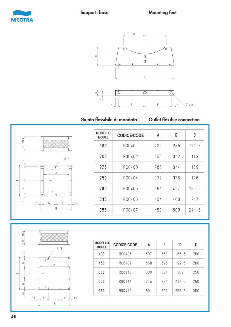
Supporti base Mounting feet
58
Giunto flessibile di mandata Outlet flexible connection
CODICE/CODEMODELLO
MODEL
CODICE/CODEMODELLOMODEL
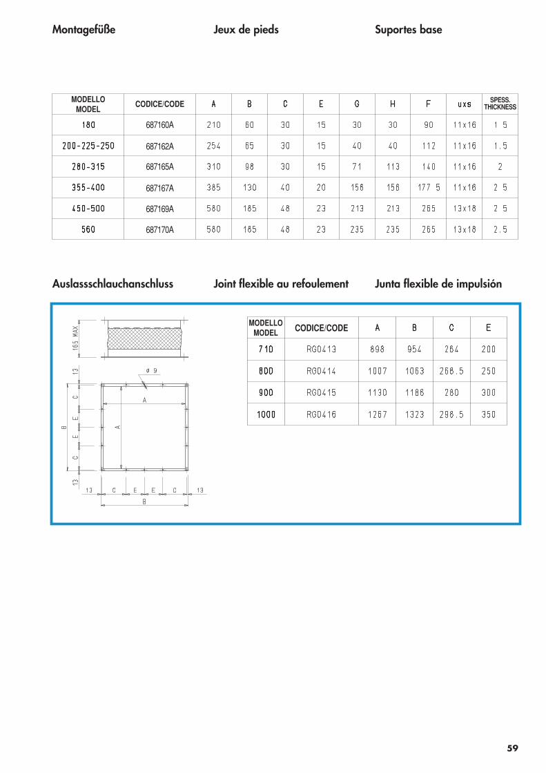
Jeux de pieds Suportes baseMontagefüße
59
Junta flexible de impulsiónAuslassschlauchanschluss Joint flexible au refoulement
CODICE/CODEMODELLOMODEL
CODICE/CODE SPESS.THICKNESS
MODELLOMODEL
687160A
687162A
687165A
687167A
687169A
687170A
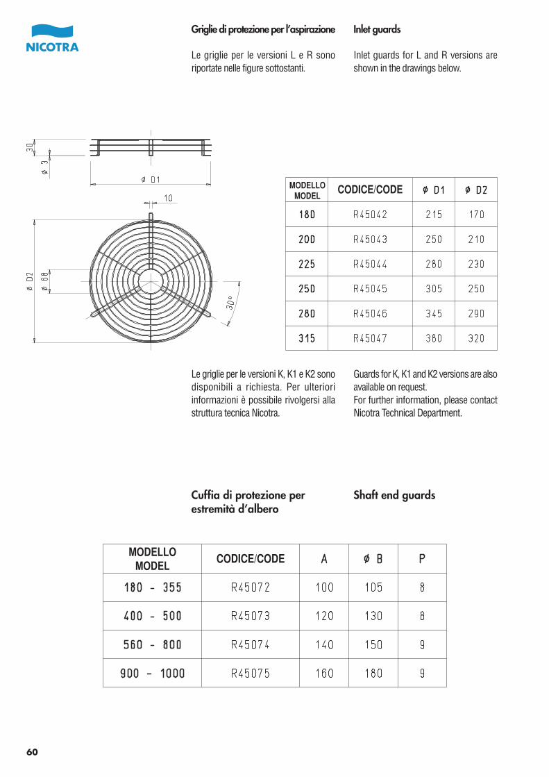
Griglie di protezione per l’aspirazione
Le griglie per le versioni L e R sonoriportate nelle figure sottostanti.
Inlet guards
Inlet guards for L and R versions areshown in the drawings below.
Le griglie per le versioni K, K1 e K2 sonodisponibili a richiesta. Per ulterioriinformazioni è possibile rivolgersi allastruttura tecnica Nicotra.
Guards for K, K1 and K2 versions are alsoavailable on request.For further information, please contactNicotra Technical Department.
60
Cuffia di protezione perestremità d’albero
Shaft end guards
CODICE/CODEMODELLOMODEL
CODICE/CODEMODELLOMODEL
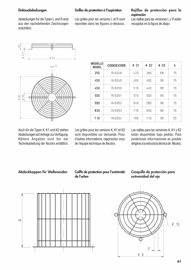
Einlassabdeckungen
Abdeckungen für die Typen L und R sindaus den nachstehenden Zeichnungenersichtlich.
Grilles de protection à l’aspiration
Les grilles pour les versions L et R sontreportées dans les figures ci-dessous.
Rejillas de protección para laaspiraciónLas rejillas para las versiones L y R estánrecogidas en la figura de abajo.
Auch für die Typen K, K1 und K2 stehenAbdeckungen auf Anfrage zur Verfügung.Nähere Angaben sind bei derTechnikabteilung der Nicotra erhältlich.
Les grilles pour les versions K, K1 et K2sont disponibles sur demande. Pourd’autres informations, rapprochez vousde l’équipe technique de Nicotra.
Las rejillas para las versiones K, K1 y K2están disponibles bajo pedido. Paraposteriores informaciones es posibledirigirse a la estructura técnica de Nicotra.
61
Coiffe de protection pour l’extrémitéde l’arbre
Casquillo de protección paraextremidad del eje
Abdeckkappen für Wellenenden
CODICE/CODEMODELLO
MODEL
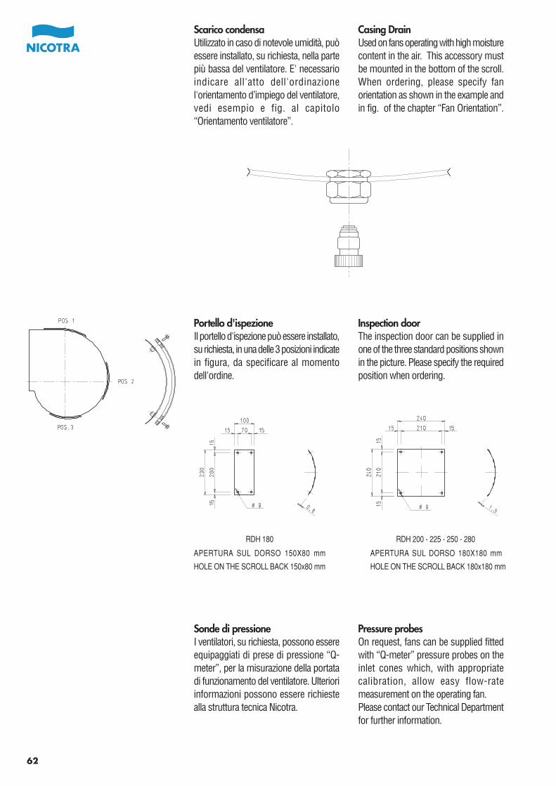
Scarico condensaUtilizzato in caso di notevole umidità, puòessere installato, su richiesta, nella partepiù bassa del ventilatore. E' necessarioindicare all'atto dell'ordinazionel'orientamento d’impiego del ventilatore,vedi esempio e fig. al capitolo“Orientamento ventilatore”.
Casing DrainUsed on fans operating with high moisturecontent in the air. This accessory mustbe mounted in the bottom of the scroll.When ordering, please specify fanorientation as shown in the example andin fig. of the chapter “Fan Orientation”.
Portello d'ispezioneIl portello d'ispezione può essere installato,su richiesta, in una delle 3 posizioni indicatein figura, da specificare al momentodell'ordine.
Inspection doorThe inspection door can be supplied inone of the three standard positions shownin the picture. Please specify the requiredposition when ordering.
62
Sonde di pressioneI ventilatori, su richiesta, possono essereequipaggiati di prese di pressione “Q-meter”, per la misurazione della portatadi funzionamento del ventilatore. Ulterioriinformazioni possono essere richiestealla struttura tecnica Nicotra.
Pressure probesOn request, fans can be supplied fittedwith “Q-meter” pressure probes on theinlet cones which, with appropriatecalibration, allow easy flow-ratemeasurement on the operating fan.Please contact our Technical Departmentfor further information.
HOLE ON THE SCROLL BACK 150x80 mm HOLE ON THE SCROLL BACK 180x180 mm
APERTURA SUL DORSO 150X80 mm APERTURA SUL DORSO 180X180 mm
RDH 180 RDH 200 - 225 - 250 - 280
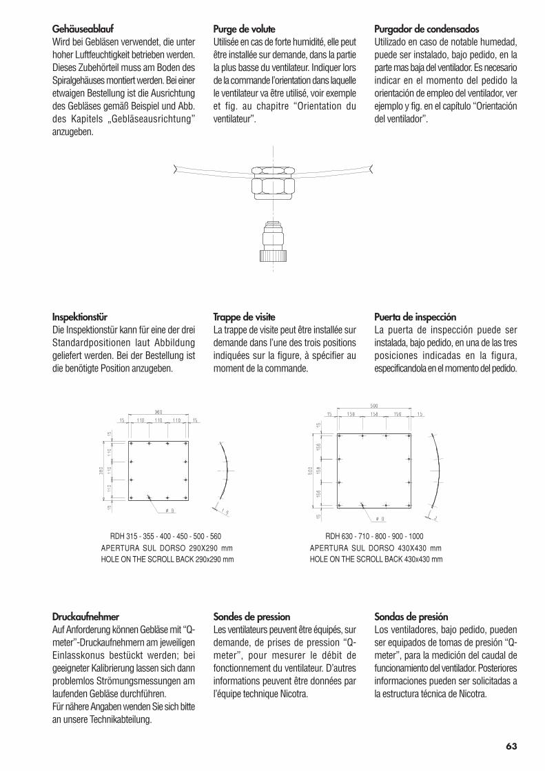
Purge de voluteUtilisée en cas de forte humidité, elle peutêtre installée sur demande, dans la partiela plus basse du ventilateur. Indiquer lorsde la commande l’orientation dans laquellele ventilateur va être utilisé, voir exempleet fig. au chapitre “Orientation duventilateur”.
Purgador de condensadosUtilizado en caso de notable humedad,puede ser instalado, bajo pedido, en laparte mas baja del ventilador. Es necesarioindicar en el momento del pedido laorientación de empleo del ventilador, verejemplo y fig. en el capítulo “Orientacióndel ventilador”.
GehäuseablaufWird bei Gebläsen verwendet, die unterhoher Luftfeuchtigkeit betrieben werden.Dieses Zubehörteil muss am Boden desSpiralgehäuses montiert werden. Bei eineretwaigen Bestellung ist die Ausrichtungdes Gebläses gemäß Beispiel und Abb.des Kapitels „Gebläseausrichtung”anzugeben.
Trappe de visiteLa trappe de visite peut être installée surdemande dans l’une des trois positionsindiquées sur la figure, à spécifier aumoment de la commande.
Puerta de inspecciónLa puerta de inspección puede serinstalada, bajo pedido, en una de las tresposiciones indicadas en la figura,especificandola en el momento del pedido.
InspektionstürDie Inspektionstür kann für eine der dreiStandardpositionen laut Abbildunggeliefert werden. Bei der Bestellung istdie benötigte Position anzugeben.
63
Sondes de pressionLes ventilateurs peuvent être équipés, surdemande, de prises de pression “Q-meter”, pour mesurer le débit defonctionnement du ventilateur. D’autresinformations peuvent être données parl’équipe technique Nicotra.
Sondas de presiónLos ventiladores, bajo pedido, puedenser equipados de tomas de presión “Q-meter”, para la medición del caudal defuncionamiento del ventilador. Posterioresinformaciones pueden ser solicitadas ala estructura técnica de Nicotra.
DruckaufnehmerAuf Anforderung können Gebläse mit “Q-meter”-Druckaufnehmern am jeweiligenEinlasskonus bestückt werden; beigeeigneter Kalibrierung lassen sich dannproblemlos Strömungsmessungen amlaufenden Gebläse durchführen.Für nähere Angaben wenden Sie sich bittean unsere Technikabteilung.
HOLE ON THE SCROLL BACK 290x290 mm HOLE ON THE SCROLL BACK 430x430 mmAPERTURA SUL DORSO 290X290 mm
RDH 315 - 355 - 400 - 450 - 500 - 560APERTURA SUL DORSO 430X430 mm
RDH 630 - 710 - 800 - 900 - 1000
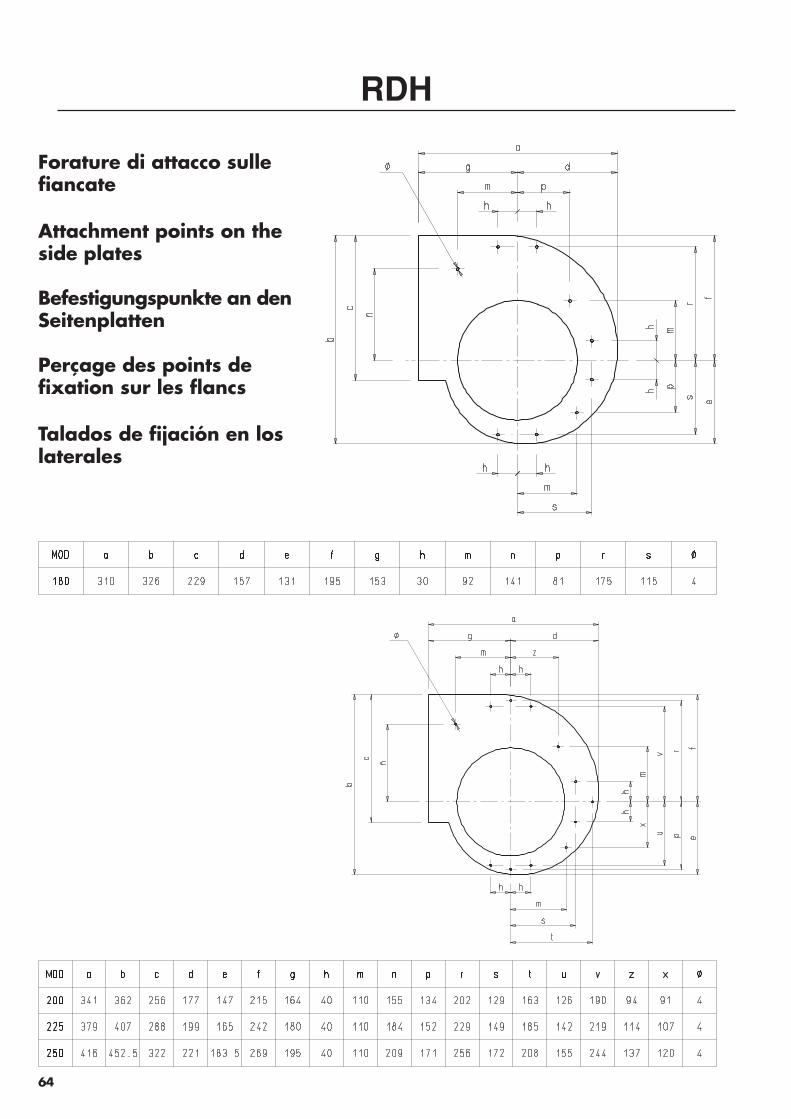
Forature di attacco sullefiancate
Attachment points on theside plates
Befestigungspunkte an denSeitenplatten
Perçage des points defixation sur les flancs
Talados de fijación en loslaterales
RDH
64
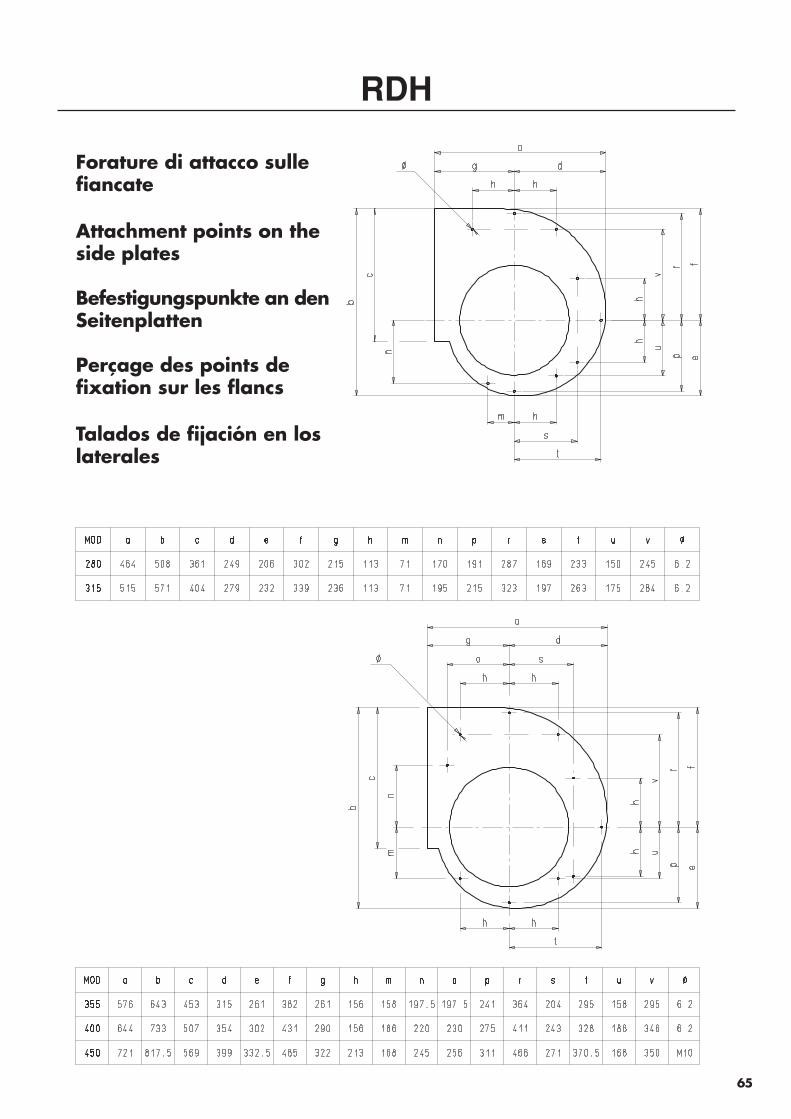
RDH
Forature di attacco sullefiancate
Attachment points on theside plates
Befestigungspunkte an denSeitenplatten
Perçage des points defixation sur les flancs
Talados de fijación en loslaterales
65
RDH
Forature di attacco sullefiancate
Attachment points on theside plates
Befestigungspunkte an denSeitenplatten
Perçage des points defixation sur les flancs
Talados de fijación en loslaterales
66
67
VITI DA UTILIZZARE PER IL FISSAGGIO DEI SUPPORTI BASESCREWS TO BE USED TO ATTACH MOUNTING FEET
VERWENDBARE SCHRAUBEN ZUR BEFESTIGUNG VON STANDFÜßENVIS A UTILISER POUR LA FIXATION DES SUPPORTS
TORNILLOS QUE PERMITEN LA FIJACIÓN DE LOS SOPORTES
MODELLO TIPO DI VITE FILETTATURAMODEL TYPE OF SCREW THREAD
Vite autofilettanteSelf-threading screw
Selbstschneidende Schraube AB 6,3 ISO 1478Vis autotaraudeuse
Tornillo autorroscante
Vite autofilettanteSelf-threading screw
Selbstschneidende Schraube AB 8 ISO 1478Vis autotaraudeuse
Tornillo autorroscante
Vite metricaMetric screw
Metrische Schraube M10 ISO 724Vis métrique
Tornillo métrico
180
200
225
250
280
315
355
400
450
500
560
esempio di lettura
example of reading
Auswahlbeispiel
exemple de lecture
ejemplo de lecturaPressione totaleTotal pressureGesamtdruck 1480Pression totalePresión total
Volume d’ariaAir volumeVolumen 24.000 m3/hDébit d’airCaudal de aire
Pressione dinamicaVelocity pressureDynamischer Druck 65 PaPression dynamiquePresión dinámica
Numero giri della ventolaR.p.m. of the impellerDrehzahl des Laufrades 1534Vitesse de rotation de la turbineNúmero de vueltas del rodete
Rendimento tot.Total efficiencyGesamt Wirkungsgrad 81.3% (*)Rendement totalRendimiento total
Potenza assorbitaAbsorbed powerAufgenommene Leistung 12.132 kw (**)Puissance absorbéePotencia absorbida
Livello di potenza sonoraSound power levelSchalleistungsgrad 91.6 dB (A)Niveau de puissance sonoreNivel de potencia sonora
Velocità aria in uscitaAir outlet velocityAusblasgeschwindigkeit 10.4 m/sVitesse de sortie d’airVelocidad de salida del aire
68
700
800
900
1000
1200
1400
1600
1700
2000
2300
2500
15
17
19
21
25
29
34
36
42
48
52
R
W
35
40
45
50
60
70
80
85
100
115
125
K
W
88
100
113
125
150
175
200
213
250
288
313
K1
W
89
102
114
127
152
178
203
216
254
292
317
K2
W
0.8
1
1.5
2
3
4
6
810
15
18.5
25
3045
49 69 82 77
63
46
30
80
85
90
95
100
1 2 3 4 5 8 9 10 14 2060
100
200
300
400
500
1000
1480
2000
3000
4000
4500
PRES
SION
E TO
TALE
TOTA
L PR
ESSU
RE
DIAMETRO GIRANTE WHEEL DIAMETER630 mm
RDH 630
K2
K1
K
R
4 5 6 7 8 9 10 14 20 30 40 50 60 70X 1000
VolumePortata
2 3 4 5 6 7 8 9 10.4 14 20 30Velocita' aria in uscita Air outlet velocity
2 3 4 5 7 10 20 100 200 500Pressione dinamica Velocity Pressure
GIR
I/mR
PM
POTE
NZA
CUSC
INET
TIBE
ARIN
G P
OW
ER
KW
m /s
REND. TOT. V.LA % - IMPELLER TOTAL EFF. %
PaN/m
LW(A) in dB(A)
= 1.2 Kg / m3
3
2
6.7
24
65
1534 32
81.5
91.6
12.1
Pa N/m
2
m/s
m /h3
Le prestazioni indicate si riferiscono ad installazione B, aspirazione Performance shown is for installation type B, free inlet -libera - mandata canalizzata, e non tengono conto di eventuali ducted outlet, and doesn't include the effects ofaccessori nel flusso d'aria. appurtenances in the airstream.La potenza assorbita non include le perdite della trasmissione. Power rating kW doesn't include drive losses.La Certificazione AMCA si riferisce alle sole prestazioni aerauliche. The AMCA Certified Ratings Seal applies to Air Performance only.12.100 + 0.032 = 12.132 kW
12.13212.100
81.5. = 81.3%( )
2500
3000
3500
4000
4500
5000
5500
6000
6800
7500
16
20
23
26
30
33
36
40
45
49
L-R
W
0.1
0.15
0.2
0.3
0.4
0.6
0.8
1
1.5
58 62 64 62 53
41
29
70
75
80
85
90
95
0.12 0.2 0.3 0.4 0.5 0.6 0.7 0.8 1 1.250
60
70
80
90100
120
140
160
180200
250
300
400
500
600
700
800
9001000
1200
1400
1600
18002000
2500
3000
3500
PR
ESSI
ON
E TO
TALE
TOTA
L PR
ESSU
RE
DIAMETRO GIRANTE WHEEL DIAMETER180 mmRDH 180
L-R
0.4 0.5 0.7 1 1.4 2 3 4 5X 1000
VolumePortata
2 3 4 5 6 7 8 9 10 14 20 25Velocita' aria in uscita Air outlet velocity
3 4 5 7 10 20 50 70 100 200 300 400Pressione dinamica Velocity Pressure
Le prestazioni indicate si riferiscono ad installazione B, aspirazione Performance shown is for installation type B, free inlet -libera - mandata canalizzata, e non tengono conto di eventuali ducted outlet, and doesn't include the effects ofaccessori nel flusso d'aria. appurtenances in the airstream.La potenza assorbita non include le perdite della trasmissione. Power rating kW doesn't include drive losses.La Certificazione AMCA si riferisce alle sole prestazioni aerauliche. The AMCA Certified Ratings Seal applies to Air Performance only.
KW
m /s
Pa
N/m
REND.TOT.V.LA % - IMPELLER TOTAL EFF. %
m /h
m/s
PaN/m
LW(A) in dB(A)
r = 1.2 Kg / m32
3
3
2
GIR
I/mR
PM
PO
TEN
ZA C
USC
INET
TIB
EAR
ING
PO
WER
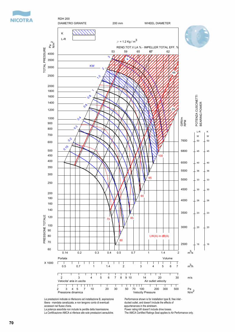
2500
3000
3500
4000
4500
5000
5500
6000
6800
7600
16
20
23
26
30
33
36
40
45
50
L-R
W
16
20
23
26
30
33
36
40
45
50
K
W
0.15
0.2
0.3
0.4
0.6
0.8
1
1.5
2
3
53 59 65 6767 62
46
29
75
80
85
90
95
100
0.14 0.2 0.3 0.4 0.5 0.7 1 1.4 260
70
80
90
100
120
140
160
180
200
250
300
350
400
450
500
600
700
800
900
1000
1200
1400
1600
1800
2000
2500
3000
3500
4000
PR
ESSI
ON
E TO
TALE
TOTA
L PR
ESSU
RE
DIAMETRO GIRANTE WHEEL DIAMETER200 mmRDH 200
K
L-R
0.5 0.7 1 1.4 2 3 4 5 6 7X 1000
VolumePortata
2 3 4 5 6 7 8 9 10 14 20 30Velocita' aria in uscita Air outlet velocity
2 3 4 5 7 10 20 30 50 70 100 200 300 500Pressione dinamica Velocity Pressure
Le prestazioni indicate si riferiscono ad installazione B, aspirazione Performance shown is for installation type B, free inlet -libera - mandata canalizzata, e non tengono conto di eventuali ducted outlet, and doesn't include the effects ofaccessori nel flusso d'aria. appurtenances in the airstream.La potenza assorbita non include le perdite della trasmissione. Power rating kW doesn't include drive losses.La Certificazione AMCA si riferisce alle sole prestazioni aerauliche. The AMCA Certified Ratings Seal applies to Air Performance only.
4
KW
m /s
Pa
N/m
REND.TOT.V.LA % - IMPELLER TOTAL EFF. %
m /h
m/s
PaN/m
LW(A) in dB(A)
r = 1.2 Kg / m32
3
3
2
GIR
I/mR
PM
PO
TEN
ZA C
USC
INET
TIB
EAR
ING
PO
WER
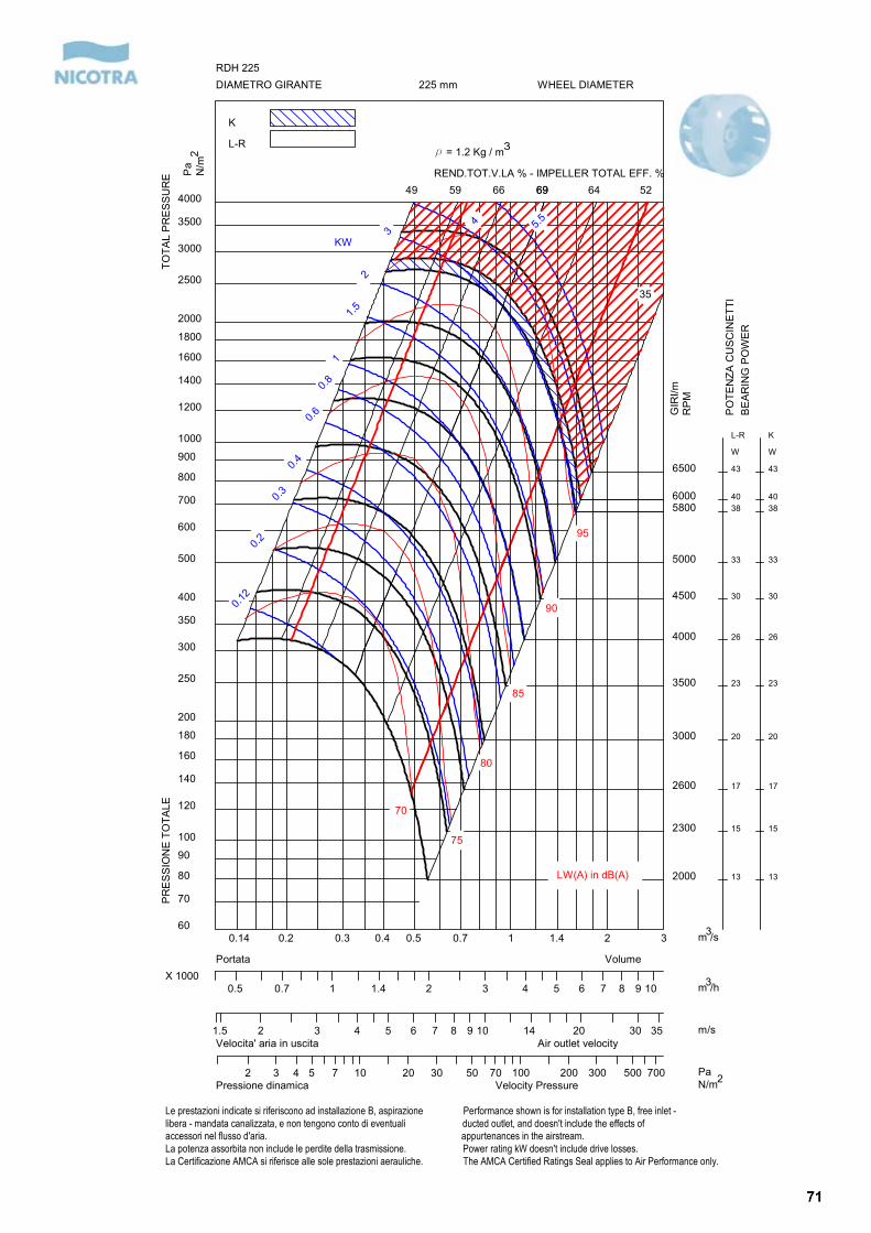
2000
2300
2600
3000
3500
4000
4500
5000
58006000
6500
13
15
17
20
23
26
30
33
3840
43
L-R
W
13
15
17
20
23
26
30
33
3840
43
K
W
0.12
0.2
0.3
0.4
0.6
0.8
1
1.5
2
34
49 59 66 6969 64 52
35
70
75
80
85
90
95
0.14 0.2 0.3 0.4 0.5 0.7 1 1.4 2 360
70
80
90
100
120
140
160
180
200
250
300
350
400
500
600
700
800
900
1000
1200
1400
1600
1800
2000
2500
3000
3500
4000
PR
ESSI
ON
E TO
TALE
TOTA
L PR
ESSU
RE
DIAMETRO GIRANTE WHEEL DIAMETER225 mmRDH 225
K
L-R
0.5 0.7 1 1.4 2 3 4 5 6 7 8 9 10X 1000
VolumePortata
1.5 2 3 4 5 6 7 8 9 10 14 20 30 35Velocita' aria in uscita Air outlet velocity
2 3 4 5 7 10 20 30 50 70 100 200 300 500 700Pressione dinamica Velocity Pressure
Le prestazioni indicate si riferiscono ad installazione B, aspirazione Performance shown is for installation type B, free inlet -libera - mandata canalizzata, e non tengono conto di eventuali ducted outlet, and doesn't include the effects ofaccessori nel flusso d'aria. appurtenances in the airstream.La potenza assorbita non include le perdite della trasmissione. Power rating kW doesn't include drive losses.La Certificazione AMCA si riferisce alle sole prestazioni aerauliche. The AMCA Certified Ratings Seal applies to Air Performance only.
5.5
KW
m /s
Pa
N/m
REND.TOT.V.LA % - IMPELLER TOTAL EFF. %
m /h
m/s
PaN/m
LW(A) in dB(A)
r = 1.2 Kg / m32
3
3
2
GIR
I/mR
PM
PO
TEN
ZA C
USC
INET
TIB
EAR
ING
PO
WER
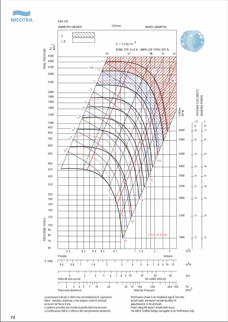
72
Le prestazioni indicate si riferiscono ad installazione B, aspirazionelibera - mandata canalizzata, e non tengono conto di eventualiaccessori nel flusso d’aria.La potenza assorbita non include le perdite della trasmissione.La certificazione AMCA si riferisce alle sole prestazioni aerauliche.
Performance shown is for installation type B, free inlet-ducted outlet, and doesn’t include the effect ofappuntenances in the airstream.Power rating kW doesn’t include drive losses.The AMCA Certified Ratings Seal applies to Air Performance only.
PRES
SION
E TO
TALE
TOTA
L PR
ESSU
RE
DIAMETRO GIRANTE WHEEL DIAMETER
VolumePortata
Velocità aria uscita Air outlet velocity
Pressione dinamica Velocity Pressure
POTE
NZA
CU
SCIN
ETTI
BEAR
ING
PO
WER
1800
2300
2800
3200
3600
4000
4600
5400
6000
12
15
18
21
24
26
30
36
40
L-R
W
22
28
34
38
43
48
55
65
72
K
W
0.20.3
0.40.6
0.81
1.52
34 5.5
7.5
53 67 7676 72 61
46
31
75
80
85
90
95
100
0.2 0.3 0.4 0.5 0.7 1 1.4 2 360
70
80
90
100
120
140
160
180
200
250
300
350
400
500
600
700
800
900
1000
1200
1400
1600
1800
2000
2500
3000
3500
4000
4500
250 mm
RDH 250
K
L-R
0.6 0.8 1 1.4 2 3 4 5 6 7 8 9 10 12X 1000
2 3 4 5 6 7 8 9 10 14 20 30
2 3 4 5 7 10 20 50 70 100 200 500 700
KW
m /s
Pa N/m
m /h
m/s
PaN/m
LW (A) in dB(A)
= 1.2 Kg / m 3
2
3
3
2
GIR
I/mR
PM
REND. TOT. V.LA % - IMPELLER TOTAL EFF. %
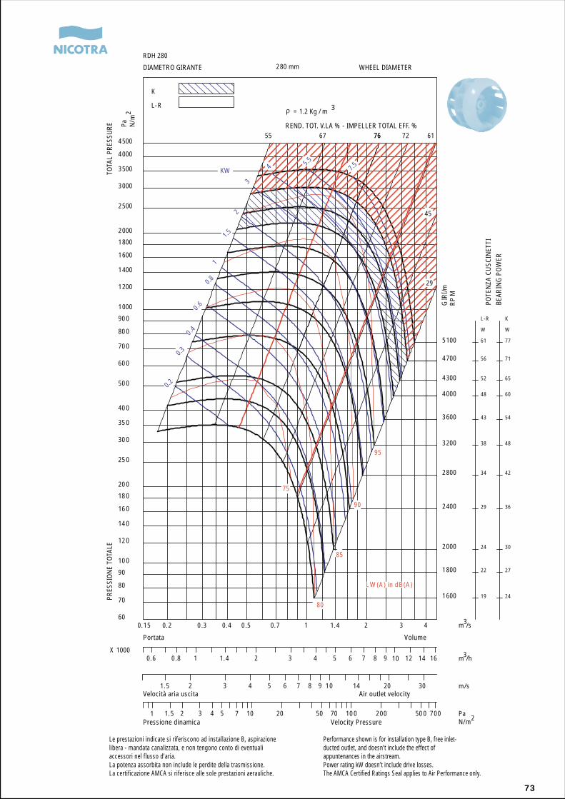
73
REND. TOT. V.LA % - IMPELLER TOTAL EFF. %
1600
1800
2000
2400
2800
3200
3600
4000
4300
4700
5100
19
22
24
29
34
38
43
48
52
56
61
L-R
W
24
27
30
36
42
48
54
60
65
71
77
K
W
0.20.3
0.40.6
0.81
1.52
3
4 5.5
7.5
55 67 7676 72 61
45
29
75
80
85
90
95
0.15 0.2 0.3 0.4 0.5 0.7 1 1.4 2 3 460
70
80
90
100
120
140
160
180
200
250
300
350
400
500
600
700
800
900
1000
1200
1400
1600
1800
2000
2500
3000
3500
4000
4500
280 mm
RDH 280
K
L-R
0.6 0.8 1 1.4 2 3 4 5 6 7 8 9 10 12 14 16X 1000
1.5 2 3 4 5 6 7 8 9 10 14 20 30
1 1.5 2 3 4 5 7 10 20 50 70 100 200 500 700
KW
m /s
Pa N/m
m /h
m/s
PaN/m
LW (A) in dB(A)
= 1.2 Kg / m 3
2
3
3
2
GIR
I/mR
PM
Le prestazioni indicate si riferiscono ad installazione B, aspirazionelibera - mandata canalizzata, e non tengono conto di eventualiaccessori nel flusso d’aria.La potenza assorbita non include le perdite della trasmissione.La certificazione AMCA si riferisce alle sole prestazioni aerauliche.
Performance shown is for installation type B, free inlet-ducted outlet, and doesn’t include the effect ofappuntenances in the airstream.Power rating kW doesn’t include drive losses.The AMCA Certified Ratings Seal applies to Air Performance only.
PRES
SION
E TO
TALE
TOTA
L PR
ESSU
RE
DIAMETRO GIRANTE WHEEL DIAMETER
VolumePortata
Velocità aria uscita Air outlet velocity
Pressione dinamica Velocity Pressure
POTE
NZA
CU
SCIN
ETTI
BEAR
ING
PO
WER
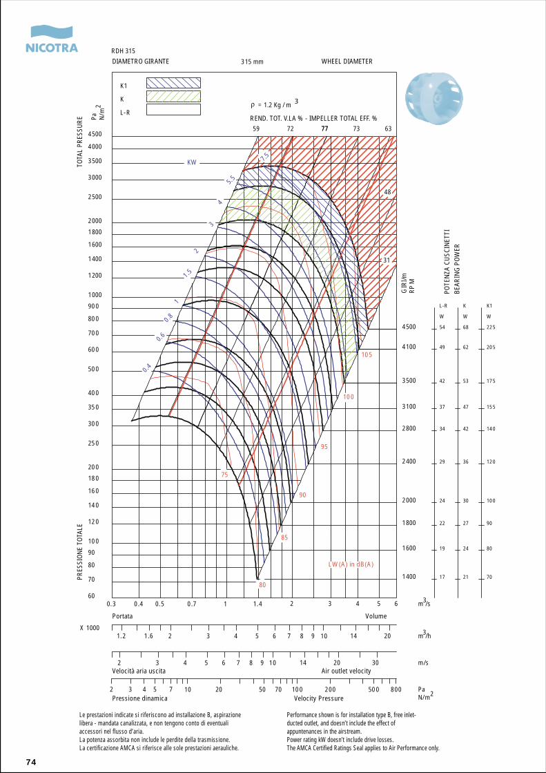
74
REND. TOT. V.LA % - IMPELLER TOTAL EFF. %
1400
1600
1800
2000
2400
2800
3100
3500
4100
4500
17
19
22
24
29
34
37
42
49
54
L-R
W
21
24
27
30
36
42
47
53
62
68
K
W
70
80
90
100
120
140
155
175
205
225
K1
W
0.4
0.6
0.8
1
1.5
2
3
4
5.5
7.5
59 72 7777 73 63
48
31
75
80
85
90
95
100
105
0.3 0.4 0.5 0.7 1 1.4 2 3 4 5 660
70
80
90
100
120
140
160
180
200
250
300
350
400
500
600
700
800
900
1000
1200
1400
1600
1800
2000
2500
3000
3500
4000
4500
315 mm
RDH 315
K1
K
L-R
1.2 1.6 2 3 4 5 6 7 8 9 10 14 20X 1000
2 3 4 5 6 7 8 9 10 14 20 30
2 3 4 5 7 10 20 50 70 100 200 500 800
KW
m /s
Pa N/m
m /h
m/s
PaN/m
LW (A) in dB(A)
= 1.2 Kg / m 32
3
3
2
GIR
I/mR
PM
Le prestazioni indicate si riferiscono ad installazione B, aspirazionelibera - mandata canalizzata, e non tengono conto di eventualiaccessori nel flusso d’aria.La potenza assorbita non include le perdite della trasmissione.La certificazione AMCA si riferisce alle sole prestazioni aerauliche.
Performance shown is for installation type B, free inlet-ducted outlet, and doesn’t include the effect ofappuntenances in the airstream.Power rating kW doesn’t include drive losses.The AMCA Certified Ratings Seal applies to Air Performance only.
PRES
SION
E TO
TALE
TOTA
L PR
ESSU
RE
DIAMETRO GIRANTE WHEEL DIAMETER
VolumePortata
Velocità aria uscita Air outlet velocity
Pressione dinamica Velocity Pressure
POTE
NZA
CU
SCIN
ETTI
BEAR
ING
PO
WER
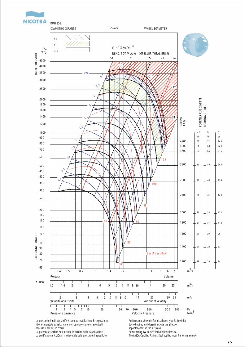
75
REND. TOT. V.LA % - IMPELLER TOTAL EFF. %
1200
1400
1600
1800
2000
2400
2800
3300
3800
4000
4200
18
21
24
27
30
36
42
50
57
60
63
L-R
W
20
24
27
31
34
41
48
56
65
68
71
K
W
74
87
99
112
124
149
174
205
236
248
260
K1
W
0.3
0.4
0.6
0.8
1
1.5
2
3
4
5.5
7.5
11
15
54 70 7777 73 62
47
31
75
80
85
90
95
100
105
0.4 0.5 0.7 1 1.4 2 3 4 5 6 760
70
80
90
100
120
140
160
180
200
250
300
350
400
450
500
600
700
800
900
1000
1200
1400
1600
1800
2000
2500
3000
3500
4000
4500
355 mm
RDH 355
K1
K
L-R
1.2 1.6 2 3 4 5 6 7 8 9 10 14 20 25X 1000
2 3 4 5 6 7 8 9 10 14 20 30 35
2 3 4 5 7 10 20 50 70 100 200 500 800
KW
m /s
Pa N/m
m /h
m/s
PaN/m
LW (A) in dB(A)
= 1.2 Kg / m 32
3
3
2
GIR
I/mR
PM
Le prestazioni indicate si riferiscono ad installazione B, aspirazionelibera - mandata canalizzata, e non tengono conto di eventualiaccessori nel flusso d’aria.La potenza assorbita non include le perdite della trasmissione.La certificazione AMCA si riferisce alle sole prestazioni aerauliche.
Performance shown is for installation type B, free inlet-ducted outlet, and doesn’t include the effect ofappuntenances in the airstream.Power rating kW doesn’t include drive losses.The AMCA Certified Ratings Seal applies to Air Performance only.
PRES
SION
E TO
TALE
TOTA
L PR
ESSU
RE
DIAMETRO GIRANTE WHEEL DIAMETER
VolumePortata
Velocità aria uscita Air outlet velocity
Pressione dinamica Velocity Pressure
POTE
NZA
CU
SCIN
ETTI
BEAR
ING
PO
WER
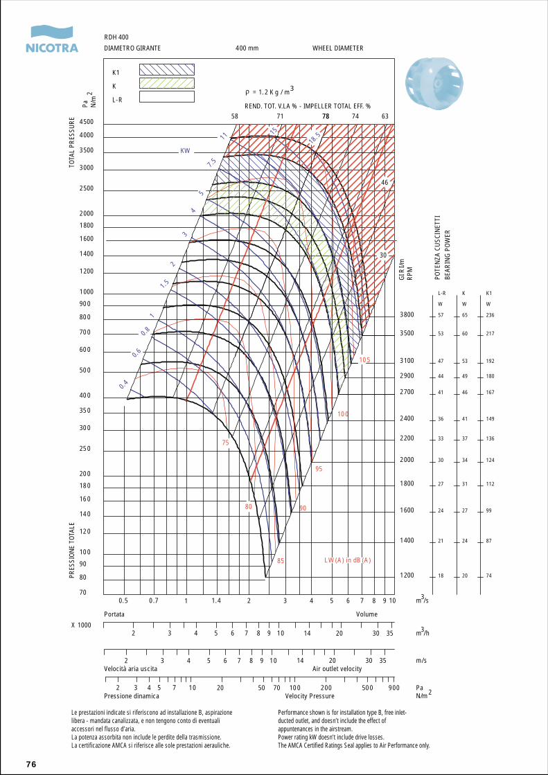
76
REND. TOT. V.LA % - IMPELLER TOTAL EFF. %
1200
1400
1600
1800
2000
2200
2400
2700
2900
3100
3500
3800
18
21
24
27
30
33
36
41
44
47
53
57
L-R
W
20
24
27
31
34
37
41
46
49
53
60
65
K
W
74
87
99
112
124
136
149
167
180
192
217
236
K1
W
0.4
0.6
0.8
1
1.5
2
3
4
5
7.5
11 15
18. 5
58 71 7878 74 63
46
30
75
80
85
90
95
100
105
0.5 0.7 1 1.4 2 3 4 5 6 7 8 9 1070
80
90
100
120
140
160
180
200
250
300
350
400
500
600
700
800
900
1000
1200
1400
1600
1800
2000
2500
3000
3500
4000
4500
400 mm
RDH 400
K1
K
L-R
2 3 4 5 6 7 8 9 10 14 20 30 35X 1000
2 3 4 5 6 7 8 9 10 14 20 30 35
2 3 4 5 7 10 20 50 70 100 200 500 900
GIR
I/mRP
M
KW
m /s
Pa N/m
m /h
m/s
PaN/m
LW (A) in dB (A)
= 1. 2 K g / m32
3
3
2
Le prestazioni indicate si riferiscono ad installazione B, aspirazionelibera - mandata canalizzata, e non tengono conto di eventualiaccessori nel flusso d’aria.La potenza assorbita non include le perdite della trasmissione.La certificazione AMCA si riferisce alle sole prestazioni aerauliche.
Performance shown is for installation type B, free inlet-ducted outlet, and doesn’t include the effect ofappuntenances in the airstream.Power rating kW doesn’t include drive losses.The AMCA Certified Ratings Seal applies to Air Performance only.
PRES
SION
E TO
TALE
TOTA
L PR
ESSU
RE
DIAMETRO GIRANTE WHEEL DIAMETER
VolumePortata
Velocità aria uscita Air outlet velocity
Pressione dinamica Velocity Pressure
POTE
NZA
CU
SCIN
ETTI
BEAR
ING
PO
WER
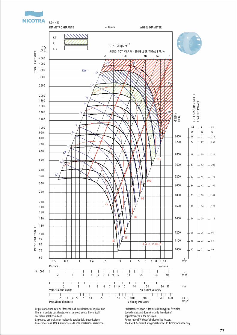
77
REND. TOT. V.LA % - IMPELLER TOTAL EFF. %
1000
1100
1200
1400
1600
1800
2000
2200
2500
2800
3200
3400
17
19
20
24
27
31
34
37
43
48
54
58
L-R
W
21
23
25
29
34
38
42
46
52
59
67
71
K
W
80
88
96
112
128
144
160
176
200
224
256
272
K1
W
0.4
0.6
0.8
1
1.5
2
3
4
5
7.5
11
15 22
51 68 7878 74 61
45
30
75
8085
90
95
100
105
0.5 0.7 1 1.4 2 3 4 5 6 7 8 9 1060
70
80
90
100
120
140
160
180
200
250
300
350
400
500
600
700
800
900
1000
1200
1400
1600
1800
2000
2500
3000
3500
4000
4500
450 mm
RDH 450
K1
K
L-R
2 3 4 5 6 7 8 9 10 14 20 30 40X 1000
2 3 4 5 6 7 8 9 10 14 20 30 35
2 3 4 5 7 10 20 50 70 100 200 500 800
KW
m /s
Pa N/m
m /h
m/s
PaN/m
LW (A) in dB(A)
= 1.2 Kg / m 32
3
3
2
GIR
I/mR
PM
Le prestazioni indicate si riferiscono ad installazione B, aspirazionelibera - mandata canalizzata, e non tengono conto di eventualiaccessori nel flusso d’aria.La potenza assorbita non include le perdite della trasmissione.La certificazione AMCA si riferisce alle sole prestazioni aerauliche.
Performance shown is for installation type B, free inlet-ducted outlet, and doesn’t include the effect ofappuntenances in the airstream.Power rating kW doesn’t include drive losses.The AMCA Certified Ratings Seal applies to Air Performance only.
PRES
SION
E TO
TALE
TOTA
L PR
ESSU
RE
DIAMETRO GIRANTE WHEEL DIAMETER
VolumePortata
Velocità aria uscita Air outlet velocity
Pressione dinamica Velocity Pressure
POTE
NZA
CU
SCIN
ETTI
BEAR
ING
PO
WER
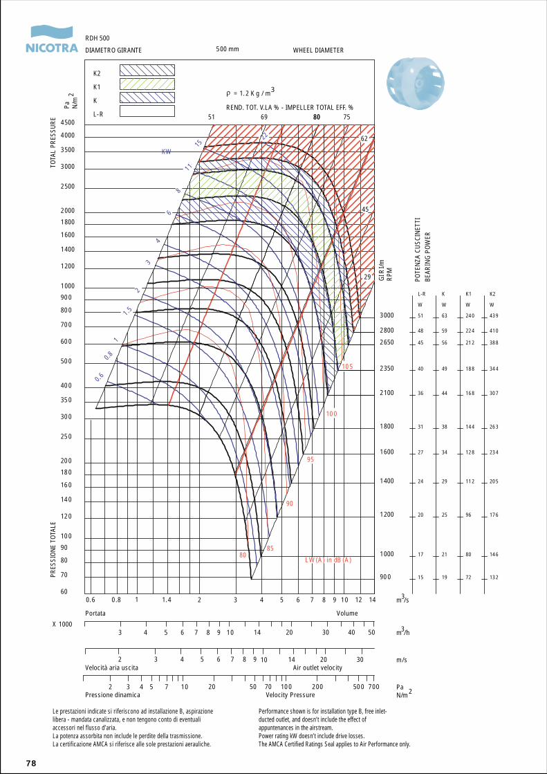
78
REND. TOT. V.LA % - IMPELLER TOTAL EFF. %
900
1000
1200
1400
1600
1800
2100
2350
2650
2800
3000
15
17
20
24
27
31
36
40
45
48
51
L-R
W
19
21
25
29
34
38
44
49
56
59
63
K
W
72
80
96
112
128
144
168
188
212
224
240
K1
W
132
146
176
205
234
263
307
344
388
410
439
K2
W
0.6
0.8
1
1.5
2
3
4
6
8
11
1522
51 69 8080 75
62
45
29
8085
90
95
100
105
0.6 0.8 1 1.4 2 3 4 5 6 7 8 9 10 12 1460
70
80
90
100
120
140
160
180
200
250
300
350
400
500
600
700
800
900
1000
1200
1400
1600
1800
2000
2500
3000
3500
4000
4500
500 mm
RDH 500
K2
K1
K
L-R
3 4 5 6 7 8 9 10 14 20 30 40 50X 1000
2 3 4 5 6 7 8 9 10 14 20 30
2 3 4 5 7 10 20 50 70 100 200 500 700
KW
m /s
Pa N/m
m /h
m/s
PaN/m
LW (A) in dB (A)
= 1. 2 K g / m3
2
3
3
2
GIR
I/mRP
M
Le prestazioni indicate si riferiscono ad installazione B, aspirazionelibera - mandata canalizzata, e non tengono conto di eventualiaccessori nel flusso d’aria.La potenza assorbita non include le perdite della trasmissione.La certificazione AMCA si riferisce alle sole prestazioni aerauliche.
Performance shown is for installation type B, free inlet-ducted outlet, and doesn’t include the effect ofappuntenances in the airstream.Power rating kW doesn’t include drive losses.The AMCA Certified Ratings Seal applies to Air Performance only.
PRES
SION
E TO
TALE
TOTA
L PR
ESSU
REDIAMETRO GIRANTE WHEEL DIAMETER
VolumePortata
Velocità aria uscita Air outlet velocity
Pressione dinamica Velocity Pressure
POTE
NZA
CU
SCIN
ETTI
BEAR
ING
PO
WER
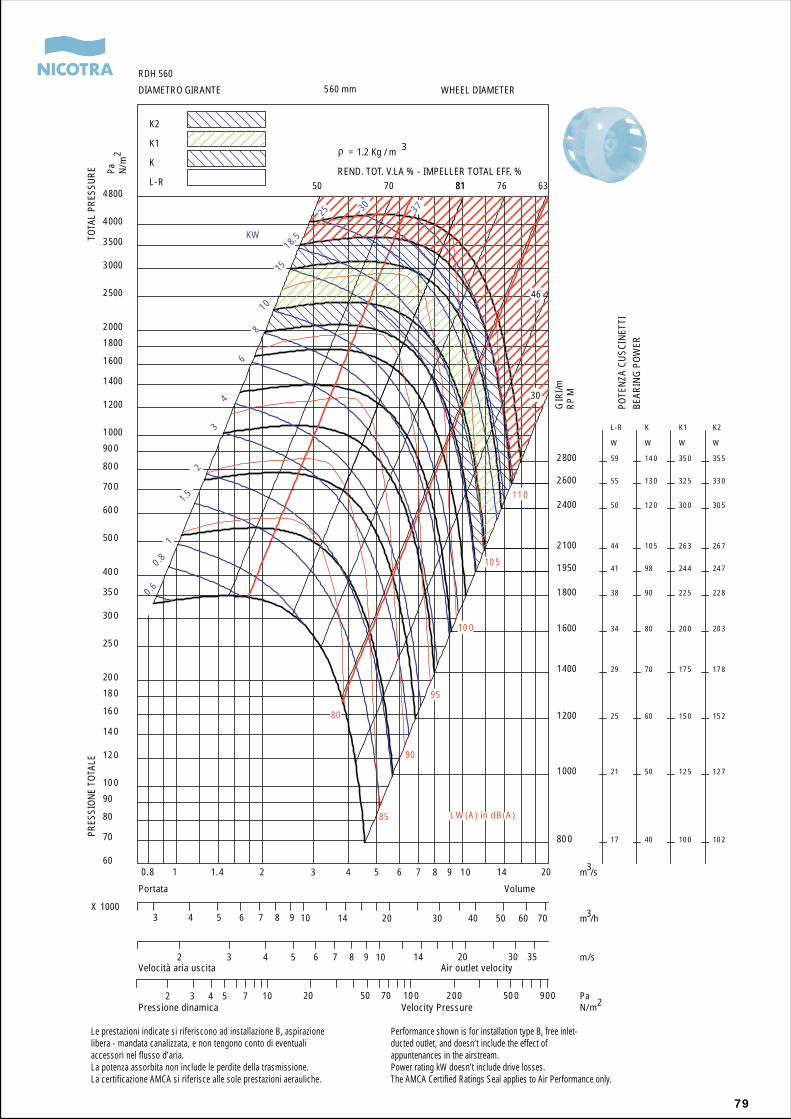
79
REND. TOT. V.LA % - IMPELLER TOTAL EFF. %
800
1000
1200
1400
1600
1800
1950
2100
2400
2600
2800
17
21
25
29
34
38
41
44
50
55
59
L-R
W
40
50
60
70
80
90
98
105
120
130
140
K
W
100
125
150
175
200
225
244
263
300
325
350
K1
W
102
127
152
178
203
228
247
267
305
330
355
K2
W
0.6
0.8
1
1.5
2
3
4
6
8
10
15
18.5
25 30 37
50 70 8181 76 63
46
30
80
85
90
95
100
105
110
0.8 1 1.4 2 3 4 5 6 7 8 9 10 14 2060
70
80
90
100
120
140
160
180
200
250
300
350
400
500
600
700
800
900
1000
1200
1400
1600
1800
2000
2500
3000
3500
4000
4800
560 mm
RDH 560
K2
K1
K
L-R
3 4 5 6 7 8 9 10 14 20 30 40 50 60 70X 1000
2 3 4 5 6 7 8 9 10 14 20 30 35
2 3 4 5 7 10 20 50 70 100 200 500 900
KW
m /s
Pa N/m
m /h
m/s
PaN/m
LW (A) in dB(A)
= 1.2 Kg / m 3
2
3
3
2
GIR
I/mR
PM
Le prestazioni indicate si riferiscono ad installazione B, aspirazionelibera - mandata canalizzata, e non tengono conto di eventualiaccessori nel flusso d’aria.La potenza assorbita non include le perdite della trasmissione.La certificazione AMCA si riferisce alle sole prestazioni aerauliche.
Performance shown is for installation type B, free inlet-ducted outlet, and doesn’t include the effect ofappuntenances in the airstream.Power rating kW doesn’t include drive losses.The AMCA Certified Ratings Seal applies to Air Performance only.
PRES
SION
E TO
TALE
TOTA
L PR
ESSU
REDIAMETRO GIRANTE WHEEL DIAMETER
VolumePortata
Velocità aria uscita Air outlet velocity
Pressione dinamica Velocity Pressure
POTE
NZA
CU
SCIN
ETTI
BEAR
ING
PO
WER
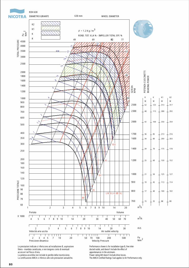
80
REND. TOT. V.LA % - IMPELLER TOTAL EFF. %
700
800
900
1000
1200
1400
1600
1700
2000
2300
2500
15
17
19
21
25
29
34
36
42
48
52
R
W
35
40
45
50
60
70
80
85
100
115
125
K
W
88
100
113
125
150
175
200
213
250
288
313
K1
W
89
102
114
127
152
178
203
216
254
292
317
K2
W
0.8
1
1.5
2
3
4
6
810
15
18.5
25
3045
49 69 8282 77
63
46
30
80
85
90
95
100
1 2 3 4 5 6 7 8 9 10 14 2060
70
80
90
100
120
140
160
180
200
250
300
350
400
500
600
700
800
900
1000
1200
1400
1600
1800
2000
2500
3000
3500
4000
4500
630 mm
RDH 630
K2
K1
K
R
4 5 6 7 8 9 10 14 20 30 40 50 60 70X 1000
2 3 4 5 6 7 8 9 10 14 20 30
2 3 4 5 7 10 20 50 70 100 200 500
GIR
I/mRP
M
KW
m /s
Pa N/m
m /h
m/s
PaN/m
LW (A) in dB (A)
= 1. 2 K g / m3
2
3
3
2
Le prestazioni indicate si riferiscono ad installazione B, aspirazionelibera - mandata canalizzata, e non tengono conto di eventualiaccessori nel flusso d’aria.La potenza assorbita non include le perdite della trasmissione.La certificazione AMCA si riferisce alle sole prestazioni aerauliche.
Performance shown is for installation type B, free inlet-ducted outlet, and doesn’t include the effect ofappuntenances in the airstream.Power rating kW doesn’t include drive losses.The AMCA Certified Ratings Seal applies to Air Performance only.
PRES
SION
E TO
TALE
TOTA
L PR
ESSU
REDIAMETRO GIRANTE WHEEL DIAMETER
VolumePortata
Velocità aria uscita Air outlet velocity
Pressione dinamica Velocity Pressure
POTE
NZA
CU
SCIN
ETTI
BEAR
ING
PO
WER
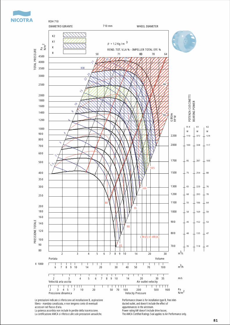
81
REND. TOT. V.LA % - IMPELLER TOTAL EFF. %
700
800
900
1000
1100
1200
1300
1500
1700
2000
2200
35
40
45
50
55
60
65
75
85
100
110
R-K
W
118
135
152
169
186
203
220
254
287
338
372
K1
W
41
47
53
59
64
70
76
88
100
117
129
K2
W
1.5
2
3
4
6
8
10
15
2225
3745 55
50 71 8383 78 64
46
30
80
85
90
95
100
105
2 3 4 5 6 7 8 9 10 14 20 3080
90
100
120
140
160
180
200
250
300
350
400
500
600
700
800
900
1000
1200
1400
1600
1800
2000
2500
3000
3500
4000
4500
710 mm
RDH 710
K2
K1
K
R
6 7 8 9 10 14 20 30 40 50 70 100X 1000
2 3 4 5 6 7 8 9 10 14 20 30 35
2 3 4 5 7 10 20 50 70 100 200 500 900
KW
m /s
Pa N/m
m /h
m/s
PaN/m
LW (A) in dB(A)
= 1.2 Kg / m 32
3
3
2
GIR
I/mR
PM
Le prestazioni indicate si riferiscono ad installazione B, aspirazionelibera - mandata canalizzata, e non tengono conto di eventualiaccessori nel flusso d’aria.La potenza assorbita non include le perdite della trasmissione.La certificazione AMCA si riferisce alle sole prestazioni aerauliche.
Performance shown is for installation type B, free inlet-ducted outlet, and doesn’t include the effect ofappuntenances in the airstream.Power rating kW doesn’t include drive losses.The AMCA Certified Ratings Seal applies to Air Performance only.
PRES
SION
E TO
TALE
TOTA
L PR
ESSU
RE
DIAMETRO GIRANTE WHEEL DIAMETER
VolumePortata
Velocità aria uscita Air outlet velocity
Pressione dinamica Velocity Pressure
POTE
NZA
CU
SCIN
ETTI
BEAR
ING
PO
WER
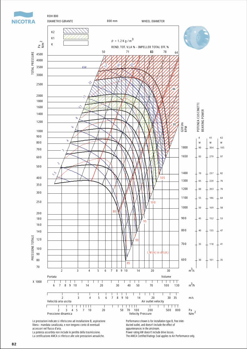
82
REND. TOT. V.LA % - IMPELLER TOTAL EFF. %
600
700
800
900
1000
1100
1200
1300
1400
1650
1800
30
35
40
45
50
55
60
65
70
83
90
K
W
101
118
135
152
169
186
203
220
237
279
304
K1
W
35
41
47
53
58
64
70
76
82
97
105
K2
W
1.5
2
3
4
6
8
11
15
22
37 45 55
50 71 8383 78 64
46
30
80
85
90
95
100
105
2 3 4 5 6 7 8 9 10 14 20 3070
80
90
100
120
140
160
180
200
250
300
350
400
500
600
700
800
900
1000
1200
1400
1600
1800
2000
2500
3000
3500
4000
4500
800 mm
RDH 800
K2
K1
K
6 7 8 9 10 14 20 30 40 50 70 100 130X 1000
2 3 4 5 6 7 8 9 10 14 20 30 35
2 3 4 5 7 10 20 50 70 100 200 500 800
KW
m /s
Pa N/m
m /h
m/s
PaN/m
LW (A) in dB (A)
= 1. 2 K g / m32
3
3
2
GIR
I/mRP
M
Le prestazioni indicate si riferiscono ad installazione B, aspirazionelibera - mandata canalizzata, e non tengono conto di eventualiaccessori nel flusso d’aria.La potenza assorbita non include le perdite della trasmissione.La certificazione AMCA si riferisce alle sole prestazioni aerauliche.
Performance shown is for installation type B, free inlet-ducted outlet, and doesn’t include the effect ofappuntenances in the airstream.Power rating kW doesn’t include drive losses.The AMCA Certified Ratings Seal applies to Air Performance only.
PRES
SION
E TO
TALE
TOTA
L PR
ESSU
RE
DIAMETRO GIRANTE WHEEL DIAMETER
VolumePortata
Velocità aria uscita Air outlet velocity
Pressione dinamica Velocity Pressure
POTE
NZA
CU
SCIN
ETTI
BEAR
ING
PO
WER
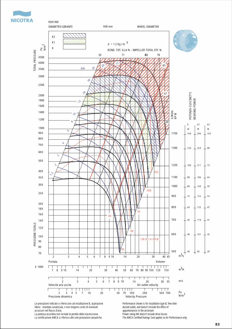
83
REND. TOT. V.LA % - IMPELLER TOTAL EFF. %
500
600
700
800
900
1000
1100
1250
1500
1750
40
48
56
64
72
80
88
100
120
140
K
W
85
101
118
135
152
169
186
211
254
296
K1
W
29
35
41
47
53
59
64
73
88
103
K2
W
1.52
3
4
68
1015
2030
45
60
75
50 71 8383 78
65
47
30
80
85
90
95
100
105
2 3 4 5 6 7 8 9 10 14 20 30 40 4570
80
90
100
120
140
160
180
200
250
300
350
400
500
600
700
800
900
1000
1200
1400
1600
1800
2000
2500
3000
3500
4000
4500
900 mm
RDH 900
K2
K1
K
7 8 9 10 14 20 30 40 50 60 70 80 90 100 120 150X 1000
2 3 4 5 6 7 8 9 10 14 20 30 35
2 3 4 5 7 10 20 50 70 100 200 500 700
KW
m /s
Pa N/m
m /h
m/s
PaN/m
LW (A) in dB(A)
= 1.2 Kg / m 32
3
3
2
GIR
I/mR
PM
Le prestazioni indicate si riferiscono ad installazione B, aspirazionelibera - mandata canalizzata, e non tengono conto di eventualiaccessori nel flusso d’aria.La potenza assorbita non include le perdite della trasmissione.La certificazione AMCA si riferisce alle sole prestazioni aerauliche.
Performance shown is for installation type B, free inlet-ducted outlet, and doesn’t include the effect ofappuntenances in the airstream.Power rating kW doesn’t include drive losses.The AMCA Certified Ratings Seal applies to Air Performance only.
PRES
SION
E TO
TALE
TOTA
L PR
ESSU
RE
DIAMETRO GIRANTE WHEEL DIAMETER
VolumePortata
Velocità aria uscita Air outlet velocity
Pressione dinamica Velocity Pressure
POTE
NZA
CU
SCIN
ETTI
BEAR
ING
PO
WER
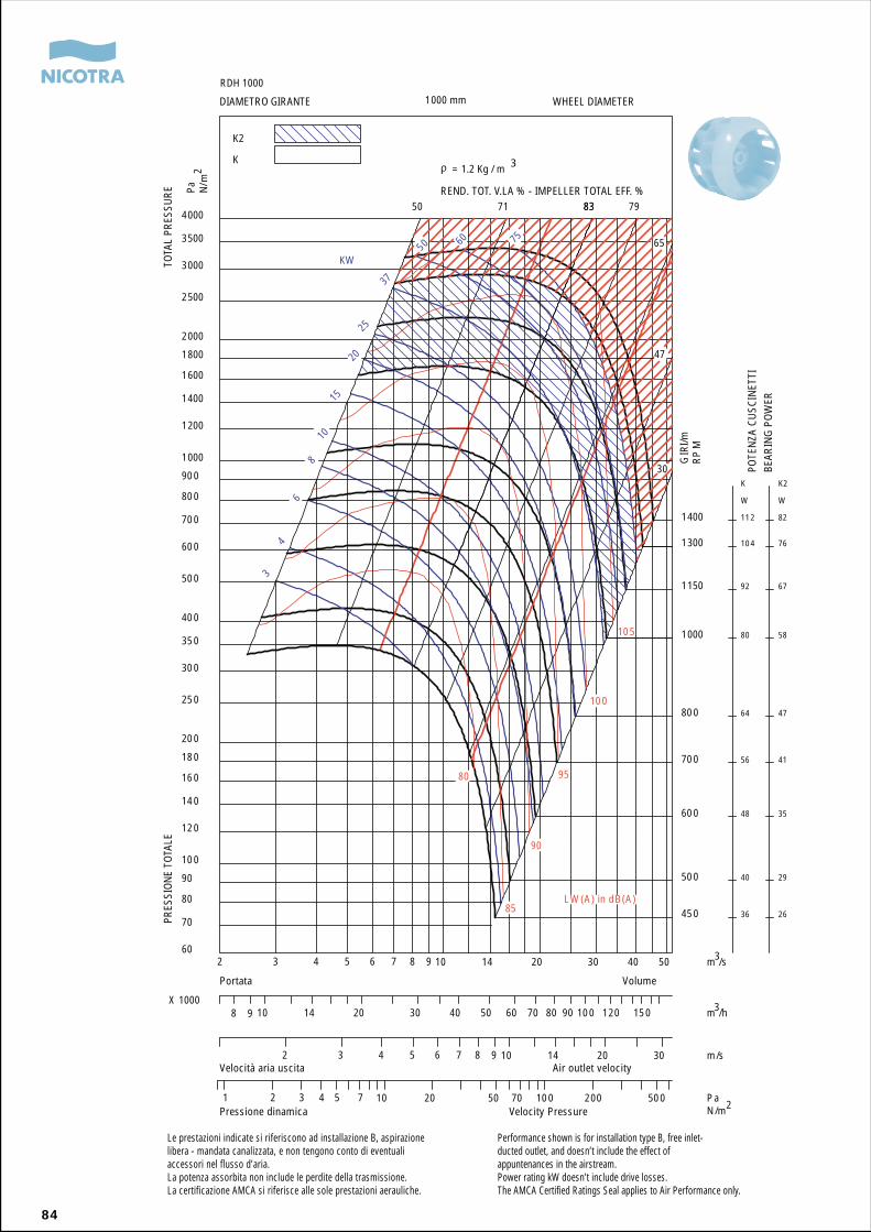
84
REND. TOT. V.LA % - IMPELLER TOTAL EFF. %
450
500
600
700
800
1000
1150
1300
1400
36
40
48
56
64
80
92
104
112
K
W
26
29
35
41
47
58
67
76
82
K2
W
34
68
1015
2025
37
50 60 75
KW
50 71 8383 79
65
47
30
80
85
90
95
100
105
2 3 4 5 6 7 8 9 10 14 20 30 40 50 m /s60
70
80
90
100
120
140
160
180
200
250
300
350
400
500
600
700
800
900
1000
1200
1400
1600
1800
2000
2500
3000
3500
4000
GIR
I/mR
PM
Pa N/m
1000 mm
K2
K
8 9 10 14 20 30 40 50 60 70 80 90 100 120 150 m /hX 1000
2 3 4 5 6 7 8 9 10 14 20 30 m/s
1 2 3 4 5 7 10 20 50 70 100 200 500 PaN /m
LW (A) in dB(A)
RDH 1000
= 1.2 Kg / m 3
2
3
3
2
Le prestazioni indicate si riferiscono ad installazione B, aspirazionelibera - mandata canalizzata, e non tengono conto di eventualiaccessori nel flusso d’aria.La potenza assorbita non include le perdite della trasmissione.La certificazione AMCA si riferisce alle sole prestazioni aerauliche.
Performance shown is for installation type B, free inlet-ducted outlet, and doesn’t include the effect ofappuntenances in the airstream.Power rating kW doesn’t include drive losses.The AMCA Certified Ratings Seal applies to Air Performance only.
PRES
SION
E TO
TALE
TOTA
L PR
ESSU
RE
DIAMETRO GIRANTE WHEEL DIAMETER
VolumePortata
Velocità aria uscita Air outlet velocity
Pressione dinamica Velocity Pressure
POTE
NZA
CU
SCIN
ETTI
BEAR
ING
PO
WER

85
Appendice
Appendix
Anhang
Appendice
Apéndice
86
Coefficienti per il calcolo dei livelli dipotenza sonoraLe tabelle che seguono elencano, perciascuna grandezza di ventilatore, i coef-ficienti occorrenti per individuare in ma-niera sufficientemente approssimata ilivelli di potenza sonora non direttamenterilevabili dai diagrammi di funzionamento,in corrispondenza di tre differenti curvedi similitudine, ed a tre differenti velocitàdi impiego. I coefficenti contraddistinticon la sigla SX si applicano a punti dilavoro sul margine sinistro della zona dinormale funzionamento (linea diagonalerossa sinistra). I coefficienti contraddistinticon la sigla DX si applicano a punti dilavoro sul margine destro della zona dinormale funzionamento (linea diagonalerossa destra). I coefficienti contraddistinticon la sigla EtaTMax si applicano a punti dilavoro sulla linea di massima efficienza.In punti intermedi tra le velocità o tra lelinee di similitudine indicate è preferibileinterpolare tra i coefficienti elencati. Ilprogramma di selezione Ventil applica ilprocedimento di calcolo completo, con-forme a BS 848 Parte 2, Appendice G, egarantisce in maniera agevole la miglioreapprossimazione dei risultati.
Coefficients for calculation of noiseratingsThe pictures below show, for each fansize, the coefficients required to estimatesufficiently approximate values of thoseSound Power Levels which cannot bedirectly read on the operating diagrams.These coefficients are given on threedifferent similarity curves and at threedifferent operating speeds. Those coeffi-cients marked with SX apply to operatingpoints located on the left border of thenormal operating area (red diagonal lineon the left). The coefficients marked withDX apply to operating points located onthe right border of the normal operatingarea (red diagonal line on the right). Thosecoefficients marked with EtaTMax apply tooperating points located on the maximumefficiency operating line. It is preferableto interpolate between the listed coeffi-cients when referring to the operatingpoints between the listed speeds or ope-rating lines.The Ventil selection program applies thecomplete calculation procedure, in accor-dance with BS 848 Part 2, Appendix G,and provides easily the best approximationof the results.
87
Coefficients pour le calcul des niveauxde puissance sonoreLes tableaux qui suivent détaillent pourchaque taille de ventilateur, les coefficientsnécessaires pour déterminer de façonsuffisamment précise les niveaux de puis-sance sonore qui ne peuvent être directe-ment relevés dans les courbes de fonc-tionnement correspondant aux troiscourbes de comparaison et aux troisvitesses d’utilisation.Les coefficients différenciés par le sigleSX s’appliquent à des points de fonction-nement sur la marge gauche de la zoned’utilisation normale (ligne diagonalerouge gauche). Les coefficients différen-ciés par le sigle DX s’appliquent à despoints de fonctionnement sur la margedroite de la zone d’utilisation normale(ligne diagonale rouge droite). Les coef-ficients différenciés par le sigle EtaTmax
s’appliquent à des points de fonctionne-ment sur la ligne du plus fort rendement.Il est préférable d’interpoler entre lescoefficients énumérés dans les pointsintermédiaires entre les vitesses ou entreles lignes de comparaison.Le programme de sélection Ventil appliquele procédé de calcul complet conforme àBS 848 Partie 2, Appendice G et garantitde manière simple une meilleure appro-ximation des résultats.
Coeficientes para el cálculo de losniveles de potencia sonoraLas tablas siguientes listan, para cadauno de los tamaños de ventilador, loscoeficientes necesarios para identificarde manera suficientemente aproximadalos niveles de potencia sonora no directa-mente determinables en los diagramasde funcionamiento, en correspondenciade tres diferentes curvas de similitud, ya tres diferentes velocidades de empleo.Los coeficientes distinguidos con la siglaSX se aplican a puntos de trabajo en elmargen izquierdo de la zona de normalfuncionamiento (línea diagonal roja izquier-da). Los coeficientes señalados con lasigla DX se aplican a puntos de trabajoen el margen derecho de la zona de normalfuncionamiento (línea diagonal roja dere-cha). Los coeficientes señalados con laEtaTMax se aplican a puntos de trabajo enla línea de máximo rendimiento.En puntos intermedios entre las velocida-des o entre las líneas de similitud indicadases preferible interpolar entre los coeficien-tes indicados.El programa de selección Ventil aplica elprocedimiento de cálculo completo, con-forme a BS 848 Parte 2, Apéndice G, ygarantiza de manera fácil la mejor aproxi-mación de los resultados.
Koeffizient für die Berechnung vonLärmwertenAus den nachstehenden Abbildungensind für jede Gebläsegröße die Koeffizien-ten ersichtlich, die erforderlich sind, umhinreichend genaue Näherungswerte fürden Schalleistungspegel zu ermitteln, diesich nicht unmittelbar am Betriebsdia-gramm ablesen lassen.Die mit SX markierten Koeffizienten geltenfür Arbeitspunkte am linken Rand desnormalen Betriebsbereichs (rote Diagonaleauf der linken Seite). Die mit DX markiertenKoeffizienten gelten für Arbeitspunkte amrechten Rand des normalen Betriebsbe-reichs (rote Diagonale auf der rechtenSeite). Die mit EtaTMax gekennzeichnetenKoeffizienten gelten für Arbeitspunkte, dieauf dem Betriebsbereich mit dem höch-sten Wirkungsgrad liegen.Sofern Arbeitspunkte zwischen aufgeführ-ten Drehzahlen bzw. Betriebsbereichenliegen, ist eine entsprechende Interpolationzu empfehlen.Das Auswahlprogramm Ventil verwendetdas vollständige Rechenverfahren gemäßBS 848 ‚Teil 2, Anhang G, und liefert mitAbstand die besten Näherungswerte.
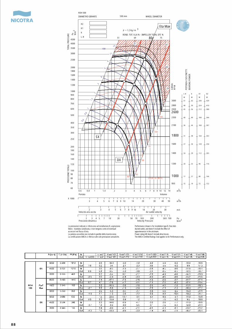
88
REND. TOT. V.LA % - IMPELLER TOTAL EFF. %
900
1000
1200
1400
1600
1800
2100
2350
2650
2800
3000
15
17
20
24
27
31
36
40
45
48
51
L-R
W
19
21
25
29
34
38
44
49
56
59
63
K
W
72
80
96
112
128
144
168
188
212
224
240
K1
W
132
146
176
205
234
263
307
344
388
410
439
K2
W
0.6
0.8
1
1.5
2
3
4
6
8
11
1522
51 69 75
62
45
29
8085
90
95
100
105
0.6 0.8 1 1.4 2 3 4 5 6 7 8 9 10 12 1460
70
80
90
100
120
140
160
180
200
250
300
350
400
500
600
700
800
900
1000
1200
1400
1600
1800
2000
2500
3000
3500
4000
4500
500 mm
RDH 500
K2
K1
K
L-R
3 4 5 6 7 8 9 10 14 20 30 40 50X 1000
2 3 4 5 6 7 8 9 10 14 20 30
2 3 4 5 7 10 20 50 70 100 200 500 700
KW
m /s
Pa N/m
m /h
m/s
PaN/m
LW (A) in dB(A)
= 1.2 Kg / m 3
2
3
3
2
GIR
I/mR
PM
2600
SX
DX
Eta Max
80
Le prestazioni indicate si riferiscono ad installazione B, aspirazionelibera - mandata canalizzata, e non tengono conto di eventualiaccessori nel flusso d’aria.La potenza assorbita non include le perdite della trasmissione.La certificazione AMCA si riferisce alle sole prestazioni aerauliche.
Performance shown is for installation type B, free inlet-ducted outlet, and doesn’t include the effect ofappuntenances in the airstream.Power rating kW doesn’t include drive losses.The AMCA Certified Ratings Seal applies to Air Performance only.
PRES
SION
E TO
TALE
TOTA
L PR
ESSU
RE
DIAMETRO GIRANTE WHEEL DIAMETER
VolumePortata
Velocità aria uscita Air outlet velocity
Pressione dinamica Velocity Pressure
POTE
NZA
CU
SCIN
ETTI
BEAR
ING
PO
WER
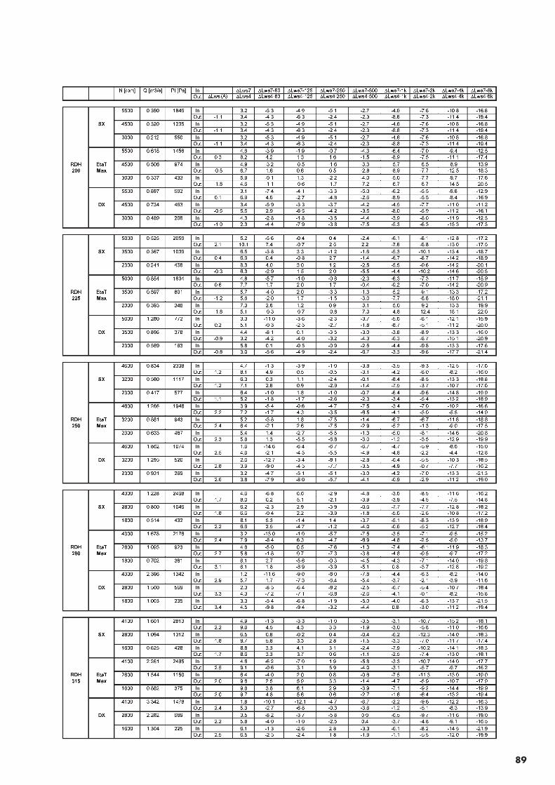
89
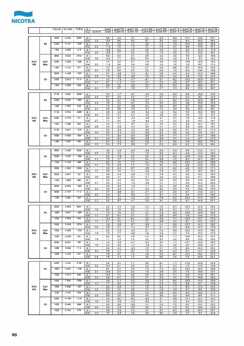
90
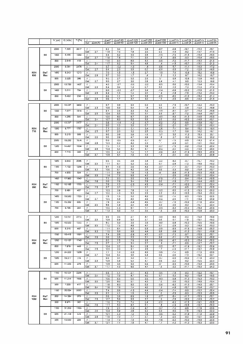
91
Le caratteristiche delle macchine riportate nel
presente catalogo, come dimensioni, prestazioni o
altre, possono essere oggetto di modifica senza
preavviso.
I cataloghi Nicotra S.p.A. sono revisionati, quando
necessario, con la pubblicazione di nuove edizioni.
È importante che gli utenti si accertino di essere in
possesso dell’ultima edizione in vigore.
Qualunque utilizzo in campo aeronautico deve
essere preventivamente comunicato a Nicotra SpA.
The characteristics of the machines stated in this
catalogue, like dimensions, performances and so
on, can be modified without previous notice.
Nicotra S.p.A. catalogues are revised, when neces-
sary, with the issue of new editions; it is important
for the user to be sure of possessing the last edition
in force.
Every application in aeronautics must be priorly
communicated to Nicotra SpA.
Die Kennzeichnen der in diesem Katalog enthalte-
nen Maschinen, wie Abmessungen, Leistungen
usw., können ohne vorherige Benachrichtigung
verändert werden.
Nicotra S.p.A. Kataloge werden mit dem Druck
neuerer Ausgaben wiederaufgenommen, wenn
notwendig. Es ist wichtig, daß die Benutzer sich
versichern, die letzte gültige Ausgabe zu besitzen.
Alle Anwendungen im Luftfahrtbereich müssen
vorher an Nicotra SpA mitgeteilt werden.
Les caractéristiques des machines indiquées dans
ce catalogue, à savoir dimensions, performances
etc., peuvent être modifiées sans aucun préavis.
Les catalogues Nicotra S.p.A. sont revisés, quand
nécessaire, avec la publication de nouvelles éditions.
Il est important que les utilisateurs s’assurent de
posséder la dernière édition en vigueur.
Toute utilisation dans le domaine aéronautique doit
être communiquée préalablement à Nicotra SpA.
Las caracteristicas de las máquinas indicadas en
el presente catálogo, como dimensiones, presta-
ciones y otros, pueden ser obieto de modificaciones
sin preaviso.
Los catálogos de Nicotra S.p.A. son revisados,
cuando es necesario, con la publicación de nuevas
ediciones. Es importante que el usuario se cerciore
de estar en posesión de la última edición en vigor.
Toda utilización en el campo aeronáutico debe ser
comunicada preventivamente a Nicotra SpA.

NICOTRA SPA - 24040 ZINGONIA (BERGAMO) - Via Modena, 18 - Tel. 035/873111 - Fax 035/884319Website: www.nicotra.it www.nicotra.com E-mail: [email protected]
RDHVENTILATORI CENTRIFUGHIA DOPPIA ASPIRAZIONECON PALE INCLINATE ALL’INDIETRO
DOUBLE INLETCENTRIFUGAL FANSWITH BACKWARDS INCLINED BLADES
DOPPELSEITIG SAUGENDERADIAL-VENTILATORENMIT RÜCKWÄRTS GEKRÜMMTEN SCHAUFELN
VENTILATEURS CENTRIFUGESA DOUBLE OUIEAVEC AUBES INCLINÉES VERS L’ARRIÈRE
VENTILADORES CENTRIFUGOSDE DOBLE ASPIRACIONCON PALAS INCLINADAS HACIA ATRAS
catalogocataloguekatalog
cataloguecatalogo D-3 Marzo 2005
March 2005März 2005Mars 2005Marzo 2005