Embed Size (px)
Citation preview
1
ATVENTILATORI CENTRIFUGHI A DOPPIA ASPIRAZIONE
DOUBLE INLET CENTRIFUGAL FANS
DOPPELSEITIG SAUGENDE RADIALVENTILATOREN
VENTILATEURS CENTRIFUGES A DOUBLE OUIE
VENTILADORES CENTRIFUGOS DE DOBLE OIDO
Catalogo | Catalogue | Katalog | Catalogue | Catalogo:
A-808/2009
Nicotra Gebhardt S.p.A
Via Modena, 18 24040 Ciserano - Loc. Zingonia (BG), Italy
Phone +39 035 873 111 Fax +39 035 884 319 E-mail [email protected]
www.nicotra-gebhardt.com
Nicotra Gebhardt GmbH
Gebhardtstrasse 19-25 74638 Waldenburg, Germany
Phone +49 (0)7942 101 0 Fax +49 (0)7942 101 170 E-mail [email protected]
www.nicotra-gebhardt.com
SPAIN Ctra. Alcalá-Villar del Olmo, Km. 2,83028810 Villalbilla-Madrid Phone +34-918846110Fax +34-918859450E-mail [email protected]
c/.Coso, 67-75, esc. 1.a,1.oB50001 Zaragoza Phone 00 34-976-290550Fax 00 34-976-298127E-mail [email protected]
BELGIUM Haeghensgoed, 13 - 00/019270 LaarnePhone +32 (0) 9/336.00.01Fax +32 (0) 9/336.00.05E-mail [email protected]
FRANCE 8 chemin des Mûriers BP 32469745 Genas cedex.Phone 00 33 (0) 472790120Fax 00 33 (0) 472790121E-mail [email protected]
SWEDEN Box 237Kraketorpsgatan 3043123 Mölndal Phone 00 46-31-874540Fax 00 46-31-878590E-mail [email protected]
GREAT BRITAIN Unit D, Rail Mill WayParkgate Business ParkRotherhamSouth YorkshireS62 6JQPhone +044-01709-780760Fax +044-01709-780762 E-mail [email protected]
Monarch House1-7 Smyth RoadBedminsterBristol Phone +44 (0)870 043 5207Fax +44 (0)870 043 5212E-mail [email protected]://www.kiloheat.co.uk/
MALAYSIA Lot 1799, Jalan BalakongTaman Perindustrian Bukit Belimbing 43300 Seri Kembangan SelangorPhone +603-89612588 Fax +603-89618337 E-mail [email protected]
Lot 1799, Bukit Belimbing Industrial AreaJalan Balakong43300 Seri KembanganSelangor Darul Ehsan Phone +603 8961 2588Fax +603 8961 8337E-mail [email protected]
THAILAND 6/29 Soi Suksawadi 2, Moo 4, Suksawadi Road, Kwang Jomthong, Khet Jomthong, Bangkok 10150Phone +662 476 1823-6Fax +662 476 1827E-mail [email protected]
SINGAPORE No. 15 West Coast Highway# 04-08 Pasir Panjang BuildingSingapore 117861 Phone (065) 6265 1522Fax (065) 6265 2400E-mail [email protected]
AUSTRALIA47 Jesica Road,Campbellfield, VIC 3061Phone +613-9357-7464Fax +613-9357-8700E-mail [email protected]
INDIAPlot no 28f, Sector-31Kasna, Greater Noida-201308U.P. INDIAPhone +91-0120-4203400Fax +91-0120-4203401E-mail [email protected]
CHINA88 Tai‘An Road, XinQiao, ShiJi, Panyu Guangzhou 511450PR CHINA Phone +86 (0)20-39960570Fax +86 (0)20-39960569 E-mail [email protected]
UNITED STATES1503 W. Misty Breeze CirKaysville, UT 84037Phone 001(801) 544-9909 Fax 001(801) 315-9400 Mobile 001(801) 694-0353E-mail [email protected]
Nicotra Gebhardt worldwide
Pag.1_Cat_AT 2006 31-03-2006 16:09 Pagina 1
C M Y CM MY CY CMY K
VENTILATORI CENTRIFUGHIA DOPPIA ASPIRAZIONE
DOUBLE INLETCENTRIFUGAL FANS
DOPPELSEITIG SAUGENDERADIAL-VENTILATOREN
VENTILATEURS CENTRIFUGESA DOUBLE OUIE
VENTILADORES CENTRIFUGOSDE DOBLE ASPIRACION
CatalogoCatalogueKatalogCatalogueCatalogo
A-8 04/06
1.640.00 - 4000/1 - 04/06
Nicotra S.p.A. certifica che i ventilatori serie AT,
versioni S, SC, C, AR e TIC, rappresentati in questo
catalogo, sono autorizzati a portare il Marchio
AMCA. Le prestazioni indicate sono basate su prove
e procedure in accordo con il documento AMCA
211, e soddisfano i requisiti del Programma AMCA
per la Cer t i f icazione del le Prestazioni.
Si veda il capitolo a pag. 38 per maggiori dettagli.
Nicotra S.p.A. certifies that AT fans of the S, SC,
C, AR, and TIC versions, shown herein, are licensed
to bear the AMCA Seal. The ratings shown are
based on tests and procedures performed in
accordance with AMCA publication 211 and comply
with the requirements of the AMCA Certified Ratings
Program.
Further details can be found on page 38.
Nicotra S.p.A. stellt sicher, dass die Ventilatoren
der Serie AT dieses Katalogs, mit den Versionen
S, SC, C, AR und TIC, von der AMCA zur Führung
ihres Siegels zugelassen sind.
Die angegebenen Leistungen basieren auf
Prüfungen und Maßnahmen gemäß AMCA 211
und kommen den Anforderungen des AMCA
Programms betreffend die Leistungszertifizierung
nach.
Weitere Details können im bezugnehmenden Kapitel
auf Seite 38 nachgelesen werden.
Nicotra S.p.A certifie que les ventilateurs AT en
versions S, SC, C, AR et TIC présentés dans ce
catalogue sont certifiés AMCA. Les performances
indiquées sont basées sur des essais et procédures
conformément au document AMCA 211 et
répondent au programme AMCA "Certification des
Performances".
Pour plus de détails se reporter au chapitre de la
page 38.
Nicotra S.p.A. certifica que los ventiladores serie
AT versiones S, SC, C, AR, y TIC representados
en este catálogo están autorizados para llevar el
sello AMCA. Las prestaciones indicadas están
basadas en pruebas y procedimientos de acuerdo
con el documento AMCA 211 y satisfacen las
normas del Programa AMCA para la Certificación
de las Prestaciones .
Ver el capítulo de la pág. 38 para mas detalles.
Aprile 2006April 2006Avril 2006April 2006Abril 2006

FOREWORDWhy a new catalogue?
The AT fans have been one of the mainstrengths in the Nicotra product rangefor over 35 years, developing, along thistime, into a wide range with countlessvariants. For all this time, the Nicotra ATCatalogue, up to version A-6, publishedin 2000, has been an important technicalreference for all those working in the fieldof ventilation. At the same time, the fansof the AT range have long been apprecia-ted for their unequalled combination ofcompactness, efficiency, quietness ofoperation and versatility, at an extremelyaffordable price.After so many years, both the productand the standards for fan performancemeasurement have evolved considerably.This is why Nicotra has found it necessaryto completely renew the AT Catalogue,on the basis of totally new tests, madein accordance with the newest measure-ment standards, so to be able to provideagain to the customers the most reliablefan performance predictions for NicotraAT Fans.Also the choice of extending the AMCAAir Performance Seal to the AT range, isin line with this target of assuring anincreased reliability and precision of theofficial performance ratings.The revised Nicotra AT Catalogue is nowgiving more space to the reference stan-dards for performance and noise ratings,and to the description of the accessoriesavailable, as a complement to the baseproduct. At the same time, the intro-ductory part of the older catalogue, whichgave general information about the useand performance of a centrifugal fan, willbe updated and re-issued as a new publi-cation, the “Nicotra Guide to selectionand operation of centrifugal fans”.With this completely revised catalogue,Nicotra will renew, into the future, itscommitment to co-operation with itsmany customers.
Zingonia, 03-11-2003
INTRODUZIONEPerché un nuovo catalogo ?
I ventilatori della serie AT sono stati unodei principali punti di forza della gammaNicotra per oltre 35 anni, sviluppandosinel tempo e dando vita ad innumerevolivarianti. Per tutto questo tempo, il cata-logo Nicotra AT, fino all’edizione A-6 del2000, è stato un sicuro riferimento per itecnici operanti nel settore della ventila-zione, mentre i ventilatori AT continuanoad essere apprezzati per la loro inegua-gliata combinazione di compattezza, effi-cienza, silenziosità e versatilità, cui sicontrappone un costo estremamente con-tenuto.In tutti questi anni, tuttavia, non solo ilprodotto, ma anche le norme e le tecno-logie di prova dei ventilatori hanno subitouna notevole evoluzione. Si è quindi resonecessario rinnovare il catalogo AT, sullabase di prove svolte in accordo con lenuove procedure di misura, così da potercontinuare a garantire agli utilizzatori lamigliore precisione possibile nel preve-dere le reali prestazioni d’impiego deiventilatori Nicotra serie AT.Anche la scelta di estendere alla serie ATla certificazione AMCA delle prestazioniaerauliche, si colloca nel quadro di questaricerca dell’affidabilità e della precisionedelle prestazioni dichiarate.Il catalogo Nicotra AT rinnovato è oracaratterizzato da più spazio destinato adescrivere i riferimenti normativi per leprocedure di prova adottate, più spaziodestinato alla descrizione degli accessoridisponibili a corredo del prodotto base,mentre la parte introduttiva generale delvecchio catalogo, che descriveva, in ter-mini generali, l’impiego e le prestazionidi un ventilatore, andrà a costituire, op-portunamente rinnovata, una nuova pub-blicazione, la “Guida Nicotra al funziona-mento e alla scelta dei ventilatoricentrifughi”.Con questo catalogo integralmente riscrit-to, Nicotra si appresta a rinnovare permolti anni a venire il proprio impegno dicollaborazione con i propri clienti.
Zingonia, 03-11-2003
2
EINFÜHRUNGWarum ein neuer Katalog ?
Die Ventilatoren der Serie AT waren über35 Jahre lang eine der Stärken in derNicotra Produktionsreihe; mit der Zeitwurden sie in unzähligen Varianten wei-terentwickelt. In diesem Zeitraum stellteder Nicotra AT-Katalog bis zur AusgabeA-6 aus dem Jahr 2000 immer einensicheren Bezugspunkt für Techniker ausdem Lüftungsbereich dar, während sichdie Ventilatoren AT weiterhin aufgrundihrer unvergleichbaren Kombination ausKompaktheit, Wirkungsgrad, Geräuschar-mut und vielseitiger Verwendbarkeit beieinem äußerst angenehmen Preis großerBeliebtheit erfreuen.In all diesen Jahren haben nicht nur dasProdukt selbst sondern auch die Normenund Prüftechnologien der Ventilatoreneinen bemerkenswerten Entwicklungs-schub erfahren.Es hat sich daher als notwendig erwiesenaufgrund der bei den Prüfungen angewand-ten neuen Messverfahren den AT-Katalogzu überholen, so dass den Anwendernein möglichst hoher Präzisionsgrad beider Leistungsberechnung garantiert wer-den kann.Damit die angegebenen aeraulischenLeistungen möglichst präzise und verläss-lich erreicht werden können, hat man sichentschlossen die AMCA Zertifizierung aufdie AT - Serie auszudehnen.Der überholte Nicotra AT Katalog widmetnun der Beschreibung der Normbezügebetreffend die Prüfverfahren, sowie dendem Basisprodukt zur Verfügung stehen-den Zubehörteile mehr Raum, währendhingegen der allgemeine Einführungspartim alten Katalog wo Einsatz und Leistun-gen des Ventilators allgemein beschriebenwerden, nun nach sorgfältiger Überholungneu veröffentlich wird, und zwar im neuen“Nicotra- Führer zum Betrieb und derAuswahl von Radialventilatoren“.Mit diesem neu verfassten Katalog willdie Firma Nicotra auf viele Jahre hinausihr Engagement ihren Kunden gegenüberverlängern.
Zingonia, 03-11-2003
AVANT PROPOSPourquoi un nouveau catalogue?
Les ventilateurs de la gamme AT ont étéau cours des ces 35 dernières années laprincipale force de production de Nicotradans une large gamme et avec de nom-breuses variantes. Au cours de cettepériode le catalogue Nicotra AT jusqu’àsa dernière version A-6 2000 a été uneréférence de travail dans le milieu de laventilation. Les ventilateurs de la gammeAT ont été appréciés pour la multitudede leurs variantes de constructions etleurs efficacité, tout en conservant unecompétitivité de prix.Après ces nombreuses années, la pro-duction et les standards ayant évoluésconsidérablement, il était nécessaire derenouveler complètement ce catalogueet de le mettre en phase avec les nouvellesnormes de mesures aérauliques et pho-niques et d’offrir ainsi un outil de sélectionplus fiable à nos clients.Le choix de la norme de mesure AMCApermet cette mise en conformité, avec lebut d’offrir un outil de sélection précis.La mise à jour du catalogue AT donneplus d’espace à la description des normesaérauliques et phoniques, à la descriptiondes accessoires, tandis que l'introductiongénérale de la vieille édition, qui décrivaiten termes généraux l'utilisation et lesperformances d'un ventilateur, va consti-tuer une nouvelle publication, la "GuideNicotra de sélection et d’utilisation desventilateurs centrifuges”.Avec cette mise à jour complète du cata-logue AT, la société Nicotra confirme sonengagement de coopération avec sesnombreux clients.
Zingonia, 03-11-2003
INTRODUCCIÓNPor qué un catalogo nuevo?
Los ventiladores AT llevan 35 años siendouno de los puntos fuertes de la gamaNicotra, desarrollándose en el tiempo ydando vida a una amplia gama de varian-tes. En dicho tiempo el catalogo de Nico-tra AT, hasta la edición A-6 del 2000, haservido de referencia para los técnicosque trabajan en el campo de ventilación.Al mismo tiempo los ventiladores ATcontinúan siendo apreciados por su com-binación de compacto, rendimiento, bajonivel sonoro y versatilidad a un costoextremadamente contenido.En todos estos años, y todavía, no sola-mente el producto, sino también las nor-mas y la tecnología de prueba de losventiladores han tenido una notable evo-lución. Por esto se ha visto necesariorenovar el catálogo AT, basado en pruebasde acuerdo con los nuevos procedimien-tos de medición, para poder continuargarantizando a los usuarios la mayorprecisión posible en la previsión de lasprestaciones reales de los ventiladoresNicotra serie AT.La elección de extender a la serie AT lacertificación AMCA de las prestacionesaerólicas esta en línea con los tareasbúsqueda de fiabilidad y de la precisiónde las prestaciones declaradas.El revisado catalogo Nicotra AT esta dandomas espacio destinado a describir lasreferencias normativas para los procedi-mientos de prueba adoptados, mas espa-cio destinado a la descripción de losaccesorios disponibles para equipar elproducto base, mientras que la parteintroductiva general del viejo catálogo,que describía en términos generales elempleo y las prestaciones de un ventila-dor, constituirá, oportunamente renovada,una nueva publicación la “Guía Nicotradel funcionamiento y selección de venti-ladores centrífugos”.Con este catalogo íntegramente reescrito,Nicotra se dispone a renovar por muchosaños su compromiso de colaboracióncon sus propios clientes.
Zingonia, 03-11-2003
3
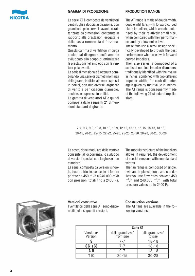
GAMMA DI PRODUZIONE
La serie AT è composta da ventilatoricentrifughi a doppia aspirazione, congiranti con pale curve in avanti, carat-terizzate da dimensioni contenute inrapporto alle prestazioni erogate, edalla bassa rumorosità di funziona-mento.Questa gamma di ventilatori impiegacoclee dal disegno specificamentesviluppato allo scopo di ottimizzarele prestazioni nell’impiego con le ven-tole pala avanti.La serie dimensionale è ottenuta com-binando una serie di diametri nominalidelle giranti, tradizionalmente espressiin pollici, con due diverse larghezzedi ventola per ciascun diametro,anch’esse espresse in pollici.La gamma di ventilatori AT è quindicomposta dalle seguenti 21 dimen-sioni standard di girante:
La costruzione modulare delle ventoleconsente, all’occorrenza, lo sviluppodi versioni speciali con larghezze nonstandard.La serie, composta da versioni singo-le, binate e trinate, consente di fornireportate da 450 m3/h a 240.000 m3/hcon pressioni totali fino a 2400 Pa.
Versioni costruttiveI ventilatori della serie AT sono dispo-nibili nelle seguenti versioni:
PRODUCTION RANGE
The AT range is made of double width,double inlet fans, with forward curvedblade impellers, which are characte-rised by their relatively small size,when compared with their performan-ce, and by a low noise level.These fans use a scroll design speci-fically developed to provide the bestperformance when used with forwardcurved impellers.Their size series is composed of aseries of nominal impeller diameters,traditionally identified with their valuein inches, combined with two differentimpeller widths for each diameter,again given by their value in inches.The AT range is consequently madeof the following 21 standard impellersizes:
The modular structure of the impellersallows, if required, the developmentof special versions, with non-standardwidths.The fan range is composed of single,twin and triple versions, and can de-liver volume flow rates between 450m3/h and 240.000 m3/h, with totalpressure values up to 2400 Pa.
Construction versionsThe AT fans are available in the fol-lowing versions:
Serie AT
Versione/Version
dalla grandezza/from size
alla grandezza/to size
S 7-7 18-18SC (C) 7-7 18-18
A R 9-7 18-18T IC 20-15 30-28
7-7, 9-7, 9-9, 10-8, 10-10, 12-9, 12-12, 15-11, 15-15, 18-13, 18-18,
20-15, 20-20, 22-15, 22-22, 25-20, 25-25, 28-20, 28-28, 30-20, 30-28
4
PRODUKTREIHE
Die Serie AT besteht aus doppelseitigsaugenden Radialventilatoren, mitvorwärts gekrümmtem Schaufeln,relativ klein gehaltenen Abmessungenim Vergleich zu den abgegebenenLeistungen, sowie einem niedrigemSchalleistungspegel.Diese Ventilatorbaureihe enthält Spi-ralgehäuse die genau dafür entwickeltwurden, um die Leistungen beivorwärts gekrümmten Schaufeln zuoptimieren.Die Maßreihe ergibt sich durch Kom-bination einer Reihe von Normdurch-messern der Laufräder, d ietraditionsgemäß in Zoll ausgedrücktwerden, mit zwei verschiedenen Lauf-radbreiten für jeden Durchmesser,ebenfalls in Zoll gemessen.Die Ventilatorenreihe AT enthält folg-lich 21 Laufradstandardabmessungen:
Die Modulbauweise der Laufrädererlaubt bei Bedarf die Entwicklungvon Spezialversionen mit Sonder-breiten.Die Serie welche aus Einzel-Zwillings-und Drillingsversionen besteht istgeeignet für Durchflussmengen von450 m3/h bis 240.000 m3/h bei einemGesamtdruck bis zu 2400 Pa.
BaureihenDie Ventilatoren der Serie AT stehenin folgenden Versionen zur Verfügung.
GAMME DE PRODUCTION
La gamme AT est composée de ven-tilateurs centrifuges double ouïe, au-bes à action, qui se caractérise parune réduction de taille si l’on compareleurs performances et leurs niveauxsonores.Cette gamme de ventilateurs utilisedes volutes développées pour optimi-ser les performances des aubes àaction.La série dimensionale est obtenue encombinant une série de diamètresnominaux des turbines, traditionnel-lement exprimés en pouces, avecdeux différentes dimensions de turbi-ne pour chaque diamètre, elles aussiexprimées en pouces.La gamme de ventilateurs AT est donccomposée par les 21 suivantes di-mensions standards de turbine:
La conception modulaire des rouespermet le développement de versionset de tailles spéciales hors standards.La gamme comprend des versionssimple, double ou triple volutes,de450 m3/h à 240.000 m3/h, sous unepression totale maximum de 2400Pa.
Versions de constructionLes ventilateurs AT existent dans lesversions suivantes:
GAMA DE PRODUCCIÓN
La gama AT se compone de ventila-dores centrífugos de doble aspiración,con rodetes de palas curvadas haciadelante, caracterizados por su tamañorelativamente pequeño, comparadoscon las prestaciones suministradasy por un bajo nivel de ruido de fun-cionamiento.Estos ventiladores usan un diseño devoluta expresamente desarrolladopara proporcionar el mejor funciona-miento cuando sea usado con rodetesde pala hacia delante.Su serie de tamaños se obtiene com-binando una serie de diámetros no-minales de los rodetes, tradicional-mente expresados en pulgadas, condos anchuras de rodete para cadadiámetro, expresado también en pul-gadas.La gama de ventiladores AT se com-pone por lo tanto de los 21 siguientesdimensiones estándar de rodete:
La estructura modular de los impul-sores permite, si se necesita, el de-sarrollo de versiones especiales, conanchuras no estándar.La serie, compuesta de versionessimples, dobles y triples, permitesuministrar caudales entre 450 m3/hy 240.000 m3/h, con presiones totaleshasta 2400 Pa.
Versiones constructivasLos ventiladores de la serie AT estándisponibles en las siguientes versio-nes:
Serie ATTyp/
Version/Versión
von Größe/De la taille/del tamaño
bis Größe/A la taille/
hasta tamaño
7-7, 9-7, 9-9, 10-8, 10-10, 12-9, 12-12, 15-11, 15-15, 18-13, 18-18,
20-15, 20-20, 22-15, 22-22, 25-20, 25-25, 28-20, 28-28, 30-20, 30-28
S 7-7 18-18SC (C) 7-7 18-18
A R 9-7 18-18T IC 20-15 30-28
5
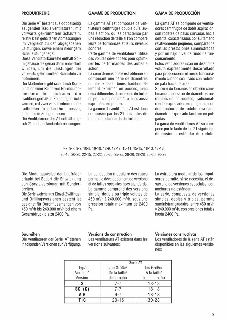
Versioni costruttive binatePer applicazioni che richiedono uningombro verticale contenuto, o quan-do la portata d’aria debba essere di-stribuita su di un vasto fronte, i ven-tilatori AT sono disponibili anche inversione binata, ovvero con due ven-tole a doppia aspirazione, montatesul medesimo albero, sostenuto dadue o tre cuscinetti.Queste versioni sono generalmentecontraddistinte dal prefisso G2. Questiventilatori sono disponibili nelle se-guenti grandezze:
Nelle versioni G2C e G2C-C2 l’uso dialberi cavi, costruiti con tubolari digrosso diametro, consente la costru-zione del ventilatore binato con duesoli cuscinetti, collocati all’estremitàdell’albero, pur mantenendo una ele-vata velocità massima di esercizio.Questa configurazione agevola note-volmente la manutenzione del venti-latore, eliminando radicalmente ledifficoltà causate da una eventualesostituzione del cuscinetto collocatotra le due giranti. Alcune versioniG2C sono dotate di due soli cuscinettipur con un albero pieno convenzio-nale.
Twin fan versionsWhere a limited fan height is required,or when the airflow must be diffusedon a wide front, AT fans are availablealso as double or twin fan versions,with two double inlet impellers on acommon shaft, supported by two orthree bearings.These versions are normally identifiedby the G2 prefix. Double fans areavailable in the following sizes:
In fan versions G2C and G2C-C2, theuse of large diameter hollow shaftsallows a design with just two bearings,mounted at the two shaft ends, butstill with a high maximum fan speed.This design simplifies fan maintenan-ce, avoiding the need to carry out acomplex operation like the changingof a bearing located between the twoimpellers. Some G2C sizes have twobearings even with a conventionalsolid shaft.
Serie AT
G 2 L 7-7 18-18S C 2 7-7 18-18G 2 C 9-7 30-28
G 2 C-C 2 20-15 30-28
Versione/Version
dalla grandezza/from size
alla grandezza/to size
6
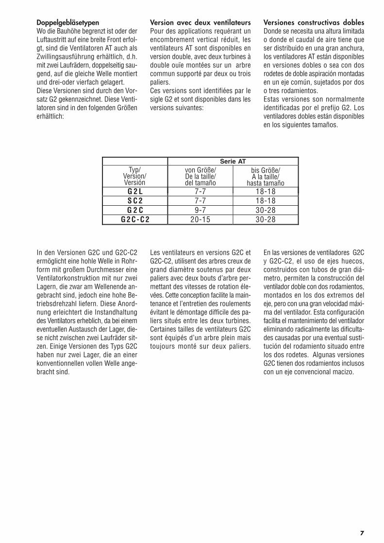
DoppelgebläsetypenWo die Bauhöhe begrenzt ist oder derLuftaustritt auf eine breite Front erfol-gt, sind die Ventilatoren AT auch alsZwillingsausführung erhältlich, d.h.mit zwei Laufrädern, doppelseitig sau-gend, auf die gleiche Welle montiertund drei-oder vierfach gelagert.Diese Versionen sind durch den Vor-satz G2 gekennzeichnet. Diese Venti-latoren sind in den folgenden Größenerhältlich:
In den Versionen G2C und G2C-C2ermöglicht eine hohle Welle in Rohr-form mit großem Durchmesser eineVentilatorkonstruktion mit nur zweiLagern, die zwar am Wellenende an-gebracht sind, jedoch eine hohe Be-triebsdrehzahl liefern. Diese Anord-nung erleichtert die Instandhaltungdes Ventilators erheblich, da bei einemeventuellen Austausch der Lager, die-se nicht zwischen zwei Laufräder sit-zen. Einige Versionen des Typs G2Chaben nur zwei Lager, die an einerkonventionnellen vollen Welle ange-bracht sind.
Version avec deux ventilateursPour des applications requérant unencombrement vertical réduit, lesventilateurs AT sont disponibles enversion double, avec deux turbines àdouble ouïe montées sur un arbrecommun supporté par deux ou troispaliers.Ces versions sont identifiées par lesigle G2 et sont disponibles dans lesversions suivantes:
Les ventilateurs en versions G2C etG2C-C2, utilisent des arbres creux degrand diamètre soutenus par deuxpaliers avec deux bouts d’arbre per-mettant des vitesses de rotation éle-vées. Cette conception facilite la main-tenance et l’entretien des roulementsévitant le démontage difficile des pa-liers situés entre les deux turbines.Certaines tailles de ventilateurs G2Csont équipés d’un arbre plein maistoujours monté sur deux paliers.
Versiones constructivas doblesDonde se necesita una altura limitadao donde el caudal de aire tiene queser distribuido en una gran anchura,los ventiladores AT están disponiblesen versiones dobles o sea con dosrodetes de doble aspiración montadasen un eje común, sujetados por doso tres rodamientos.Estas versiones son normalmenteidentificadas por el prefijo G2. Losventiladores dobles están disponiblesen los siguientes tamaños.
En las versiones de ventiladores G2Cy G2C-C2, el uso de ejes huecos,construidos con tubos de gran diá-metro, permiten la construcción delventilador doble con dos rodamientos,montados en los dos extremos deleje, pero con una gran velocidad máxi-ma del ventilador. Esta configuraciónfacilita el mantenimiento del ventiladoreliminando radicalmente las dificulta-des causadas por una eventual susti-tución del rodamiento situado entrelos dos rodetes. Algunas versionesG2C tienen dos rodamientos inclusoscon un eje convencional macizo.
Serie ATTyp/
Version/Versión
von Größe/De la taille/del tamaño
bis Größe/A la taille/
hasta tamañoG 2 L 7-7 18-18S C 2 7-7 18-18G 2 C 9-7 30-28
G 2 C-C 2 20-15 30-28
7
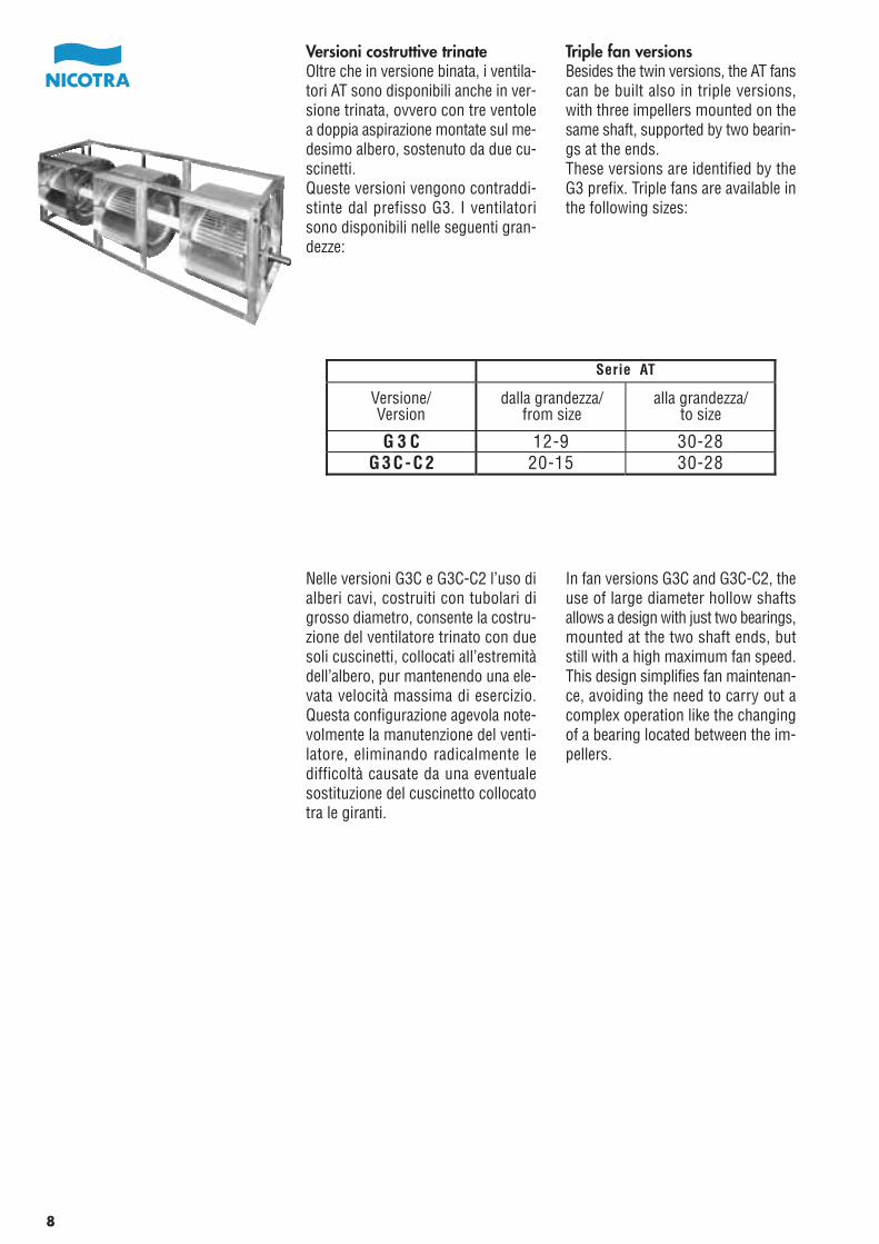
Versioni costruttive trinateOltre che in versione binata, i ventila-tori AT sono disponibili anche in ver-sione trinata, ovvero con tre ventolea doppia aspirazione montate sul me-desimo albero, sostenuto da due cu-scinetti.Queste versioni vengono contraddi-stinte dal prefisso G3. I ventilatorisono disponibili nelle seguenti gran-dezze:
Nelle versioni G3C e G3C-C2 l’uso dialberi cavi, costruiti con tubolari digrosso diametro, consente la costru-zione del ventilatore trinato con duesoli cuscinetti, collocati all’estremitàdell’albero, pur mantenendo una ele-vata velocità massima di esercizio.Questa configurazione agevola note-volmente la manutenzione del venti-latore, eliminando radicalmente ledifficoltà causate da una eventualesostituzione del cuscinetto collocatotra le giranti.
Triple fan versionsBesides the twin versions, the AT fanscan be built also in triple versions,with three impellers mounted on thesame shaft, supported by two bearin-gs at the ends.These versions are identified by theG3 prefix. Triple fans are available inthe following sizes:
In fan versions G3C and G3C-C2, theuse of large diameter hollow shaftsallows a design with just two bearings,mounted at the two shaft ends, butstill with a high maximum fan speed.This design simplifies fan maintenan-ce, avoiding the need to carry out acomplex operation like the changingof a bearing located between the im-pellers.
Serie AT
G 3 C 12-9 30-28G 3 C-C 2 20-15 30-28
Versione/Version
dalla grandezza/from size
alla grandezza/to size
8
DrillingsausführungenNeben der Zwillingsausführung sindd i e Ve n t i l a t o r e n a u c h a l sDrillingsausführung erhältlich, d.h.mit drei Laufrädern, doppelseitig sau-gend und auf die gleiche Welle mon-tiert, auf der zwei Lager sitzen.Diese Versionen werden durch denVorsatz G3 gekennzeichnet. DieseVentilatoren sind in den folgendenGrößen erhältlich:
In den Versionen G3C und G3C-C2ermöglicht eine hohle Welle in Rohr-form mit großem Durchmesser demDrillingsventilator eine Ausführungmit nur zwei Lagern, die am Wellen-ende sitzen, bei Beibehaltung der ma-ximalen Betriebsdrehzahl.Diese Anordnung erleichtert die In-standhaltung des Ventilators erheb-lich, da Probleme bei einem eventuel-len Lageraustausch zwischen zweiLaufrädern somit nicht auftreten kön-nen. Einige Versionen des Typs G2Chaben nur zwei Lager, die an einerkonventionnellen vollen Welle ange-bracht sind.
Version avec trois ventilateursA coté de la version double, la gammeAT est proposée également en versiontriple, avec trois turbines montéessur un même arbre supporté par deuxpaliers aux extrémités.Ces versions sont identifiées par lesigle G3 et sont disponibles dans lesversions suivantes :
Les ventilateurs en versions G3C etG3C-C2, utilisent des arbres creux degrand diamètre soutenus par deuxpaliers avec deux bouts d’arbre per-mettant des vitesses de rotation éle-vées. Cette conception facilite la main-tenance et l’entretien des roulementsévitant le démontage difficile des pa-liers situés entre les deux turbines.
Versiones constructivas triplesAparte de las versiones dobles, losventiladores AT están disponiblestambién en versión triple, o sea contres rodetes de doble aspiración mon-tados en el mismo eje, sujetados pordos rodamientos en los extremos.Estas versiones están identificadaspor el prefijo G3. Los ventiladorestriples están disponibles en los si-guientes tamaños:
En las versiones G3C y G3C-C2 eluso de ejes huecos, construidos contubos de gran diámetro permiten laconstrucción con dos rodamientos,montados en los dos extremos deleje, pero con una gran velocidad máxi-ma de funcionamiento. Esta configu-ración facilita el mantenimiento delventilador eliminando radicalmentelas dificultades causadas por unaeventual sustitución del rodamientosituado entre los rodetes.
Serie ATTyp/
Version/Versión
von Größe/De la taille/del tamaño
bis Größe/A la taille/
hasta tamaño
G 3 C 12-9 30-28G 3 C-C 2 20-15 30-28
9
CARATTERISTICHE COSTRUTTIVE
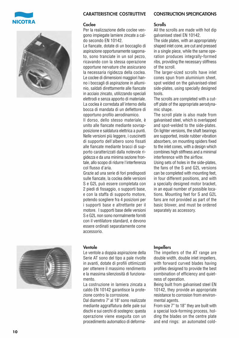
CocleePer la realizzazione delle coclee ven-gono impiegate lamiere zincate a cal-do secondo EN 10142.Le fiancate, dotate di un boccaglio diaspirazione opportunamente sagoma-to, sono tranciate in un sol pezzo,ricavando con la stessa operazioneopportune nervature che assicuranola necessaria rigidezza della coclea.Le coclee di dimensioni maggiori han-no i boccagli di aspirazione in allumi-nio, saldati direttamente alle fiancatein acciaio zincato, utilizzando specialielettrodi e senza apporto di materiale.La coclea è corredata all'interno dellabocca di mandata di un deflettore diopportuno profilo aerodinamico.Il dorso, dello stesso materiale, èunito alle fiancate mediante sovrap-posizione e saldatura elettrica a punti.Nelle versioni più leggere, i cuscinettidi supporto dell'albero sono fissatialle fiancate mediante bracci di sup-porto caratterizzati dalla notevole ri-gidezza e da una minima sezione fron-tale, allo scopo di ridurre l'interferenzacol flusso d'aria.Grazie ad una serie di fori predispostisulle fiancate, la coclea delle versioniS e G2L può essere completata con2 piedi di fissaggio, o supporti base,e con la staffa di supporto motore,potendo scegliere fra 4 posizioni peri supporti base e altrettante per ilmotore. I supporti base delle versioniS e G2L non sono normalmente forniticon il ventilatore standard, e devonoessere ordinati separatamente comeaccessorio.
VentoleLe ventole a doppia aspirazione dellaSerie AT sono del tipo a pale rivoltein avanti, dotate di profili ottimizzatiper ottenere il massimo rendimentoe la massima silenziosità di funziona-mento.La costruzione in lamiera zincata acaldo EN 10142 garantisce la prote-zione contro la corrosione.Dal diametro 7" al 18" sono realizzatemediante aggraffatura delle pale suidischi e sui cerchi di sostegno: questaoperazione viene eseguita con unprocedimento automatico di deforma-
CONSTRUCTION SPECIFICATIONS
ScrollsAll the scrolls are made with hot dipgalvanised steel EN 10142.The side plates, with an appropriatelyshaped inlet cone, are cut and pressedin a single piece, while the same ope-ration produces integrally-formedribs, providing the necessary stiffnessof the scroll.The larger-sized scrolls have inletcones spun from aluminium sheet,spot welded on the galvanised-steelside-plates, using specially designedtools.The scrolls are completed with a cut-off plate of the appropriate aerodyna-mic shape.The scroll plate is also made fromgalvanised steel, which is overlappedand spot-welded to the side-plates.On lighter versions, the shaft bearingsare supported, inside rubber vibrationabsorbers, on mounting spiders fixedto the inlet cones, with a design whichcombines high stiffness and a minimalinterference with the airflow.Using sets of holes in the side-plates,the fans of the S and G2L versionscan be completed with mounting feet,in four different positions, and witha specially designed motor bracket,in an equal number of possible loca-tions. Mounting feet for S and G2Lfans are not provided as part of thebasic blower, and must be orderedseparately as accessory.
ImpellersThe impellers of the AT range aredouble width, double inlet impellers,with forward curved blades havingprofiles designed to provide the bestcombination of efficiency and quiet-ness of operation.Being built from galvanised steel EN10142, they provide an appropriateresistance to corrosion from environ-mental agents.From size 7” to 18” they are built witha special lock-forming process, hol-ding the blades on the centre plateand end rings: an automated cold-
10
HERSTELLUNGSSPEZIFIKATIONEN
SpiralgehäuseDie Spiralgehäuse werden aus tau-chverzinktem Stahl des Typs EN10142 hergestellt.Die Seitenplatten mit formangepassterEinströmdüse sind aus einem Stückgestanzt und mit Aussteifungen ver-sehen, welche die notwendige Steifig-keit des Gehäuses gewährleisten.Die größeren Gehäuse besitzenEinströmdüsen aus Aluminium, diedirekt an die Seitenplatten mit Hilfevon speziellen Elektroden und ohnezusätzliche Materialzufuhr aus ver-zinktem Stahl geschweißt sind.Das Gehäuse erhält im Innern einLeitblech mit aerodynamischen Profil.Der Gehäuserücken aus dem gleichenMaterial ist mit den Seitenplatten dur-ch Überlappung und elektrischenPunktschweissungen verbunden.Bei den leichteren Ausführungen wer-den die Lager an die Seitenplattendurch robuste Verstrebungen mon-tiert; diese haben einen geringen Dur-chmesser um so eine Interferenz amDurchfluss möglichst gering zu halten.Dank einer Reihe von Bohrungen anden Seitenplatten kann das Gehäuseder Versionen S und G2L mit 2Standfüßen oder Stützen sowie einemMotorbock ausgestattet werden, wo-bei man zwischen 4 verschiedenenPositionen sowohl für die Stütze alsauch für den Motor auswählen kann.Die Standfüße der Versionen S undG2L werden normalerweise beimStandardventilator nicht mitgeliefertSie müssen daher separat geordertwerden.
LaufräderDie doppelseitig saugenden Laufräderder Serie AT sind mit vorwärtsgekrümmten Schaufeln ausgestattetund so profiliert, dass ein maximalerWirkungsgrad bei maximaler Laufruheerzielt werden kann.Die Ausführung aus tauchverzinktemStahl EN 10142 garantiert Antikorro-sionsschutz.Vom Durchmesser 7“ bis 18“ werdendie Schaufeln auf die Scheiben undStützringe gefalzt: dieser Vorgangwird automatisch durch Kaltverfor-mung ausgeführt, aufgrund derer ein
PARTICULARITÉS DE CONSTRUCTION
VolutesToutes les volutes sont exécutées entôle zinguée à chaud selon EN 10142.Les flancs intègrent le pavillond’aspiration, ils sont découpés etemboutis en une seule opération, unnervurage assurant la rigidité del’ensemble.Les volutes de grandes dimensionssont équipées d’ouïes en aluminiumsoudées directement sur les flancsgalvanisés en utilisant des électrodesspéciales.La volute est équipée d’un bec aurefoulement spécialement exécutésuivant un profil aéraulique.L’arrière de la volute est égalementexécutée en acier galvanisé et soudéepar point aux flancs.Dans la version sans châssis les brassupport paliers sont fixés aux flancsà l’aide d’un système rigide de brasauto-centreurs avec bague caou-tchoucs, fixés aux ouïes d’aspirationset conçus dans un soucis de combinerrigidité et minimum d’interférencedans le flux d’air alimentant les turbi-nes.Grâce à une série de trous prévus surles flancs, les ventilateurs en versionS et G2L peuvent être équipés depieds support permettant une orien-tation du refoulement dans quatrepositions et avec l’accessoire supportmoteur en nombre égal de positions.Le montage des pieds support desversions S et G2L ne fait pas partiede la version de base et doit fairel’objet d’une commande séparée com-me accessoires.
TurbinesLes turbines de la gamme AT sont àdouble aspiration, avec aubes in-clinées vers l’avant, avec un profilpermettant d’obtenir le meilleur ren-dement ainsi qu’un fonctionnementsilencieux.Elles sont réalisées en acier EN 10142,permettant une excellente résistanceà la corrosion provenant del’environnement.Du modèle 7” au 18” elles sont réa-lisées par un procédé d’assemblage,la fixation des aubes sur le disquecentral et aux anneaux extérieurs est
CARACTERÍSTICAS CONSTRUCTIVAS
VolutasPara la realización de las volutas seutiliza acero galvanizado calientesegún EN 10142.Los laterales, dotados de un oído deaspiración oportunamente perfilado,son cortados y prensados en una solapieza, obteniendo en la misma opera-ción nervios que aseguran la rigideznecesaria de la voluta.Las volutas mas grandes tienen oídosde aspiración de aluminio, soldadosdirectamente a los laterales de acerogalvanizado, usando electrodos espe-ciales y sin aportación de material.La voluta equipa en el interior de laboca de impulsión un deflector conel perfil aerodinámico apropiado.El dorso, del mismo material, se unea los laterales mediante superposicióny soldadura eléctrica por puntos.En las versiones mas ligeras, los ro-damientos de soporte del eje se fijana los laterales mediante brazos desoporte caracterizados de una notablerigidez y de una mínima sección fron-tal, con el fin de reducir la interferenciacon el flujo de aire.Gracias a una serie de taladros predi-spuestos sobre los laterales, las vo-lutas de las versiones S y G2L puedenser equipadas con 2 pies de fijación,o soportes base, y con el soportemotor, pudiendo elegir entre 4 posi-ciones para los soportes base y otrastantas para el motor. Los soportesbase de las versiones S y G2L no sonsuministrados normalmente con elventilador estándar, y deben ser pe-didos separadamente como acceso-rio.
RodetesLos rodetes de doble aspiración dela serie AT son del tipo palas curvadashacia delante, con perfiles optimiza-dos para obtener el máximo rendi-miento y el mínimo nivel sonoro defuncionamiento.La construcción en chapa cincada encaliente EN 10142 garantiza la protec-ción contra la corrosión.Del tamaño 7” a 18” están fabricadoscon un proceso especial sujetandolas palas al disco central y a los anillosde los extremos: esta operación serealiza con un proceso automático de
11

zione a freddo, che assicura un as-semblaggio meccanico affidabile conuna ottima precisione dimensionale.Dal diametro 20", le palette sono fis-sate, al disco centrale ed agli anelli ditesta, mediante una chiodatura. Que-sta soluzione garantisce un elevatogrado di sicurezza, anche nel caso difunzionamento costante con alte ve-locità e potenze.Le ventole di maggior diametro sonodotate inoltre di speciali tiranti rego-labili, che aumentano la rigidezza dellaventola nell’impiego ad alta velocità,garantendo allo stesso tempo unamigliore protezione contro le defor-mazioni accidentali. I tiranti sonoregistrati in fabbrica, durante la fasedi controllo dimensionale ed equili-bratura, da personale specializzato.Tutte le ventole AT sono equilibratestaticamente e dinamicamente, secon-do le norme ISO 1940, con grado G4.
TelaiI ventilatori delle versioni SC, C, AR,TIC, SC2, G2C, G2C-C2, G3C e G3C-C2 sono dotati di telai laterali di rin-forzo, realizzati con angolari di acciaiozincato EN 10142, saldati alle fiancate. In molte di queste versioni essi sonoanche uniti tra loro da longheronisaldati, a formare una gabbia, a formadi cubo, che sostiene la coclea assor-bendo tutte le sollecitazioni meccani-che.I componenti del telaio sono tranciati,piegati, posizionati e saldati elettrica-mente, in un ciclo di operazioni ingran parte automatizzate, ottenendocosi' la necessaria precisione dimen-sionale e la massima rigidezza.Ogni lato del telaio presenta una cop-pia di fori ad asola per il fissaggio delventilatore al basamento.Nelle esecuzioni dotate di telaio ecuscinetti a supporto, i bracci di sup-porto dei cuscinetti sono saldati altelaio stesso, in modo da scaricarecompletamente la coclea dalle reazionitrasmesse ai cuscinetti dalla rotazionedella ventola e dalla tensione dellecinghie.
forming process provides a reliablemechanical fix with high dimensionalprecision.Starting from size 20”, the AT impel-lers have the blades riveted to thecentre disk and to the end rings. Thisconstruction provides high strengthand safe operation, even when theimpellers are used at high speed andpower.The larger impellers are also providedwith special, adjustable tie-rods, whi-ch increase the impeller stiffness forhigh-speed running, and at the sametime provide a better resistance toaccidental bending. These tie-rodsare factory adjusted during the dimen-sional check and balance phase, byour specially trained personnel.All the AT impellers are statically anddynamically balanced, according toISO 1940, with grade G4.
Side framesThe AT fans of the versions SC, C,AR, TIC, SC2, G2C, G2C-C2, G3C andG3C-C2 have special, reinforcing fra-mes, made of galvanised steel EN10142 and spot-welded to the scrollsides. In many cases they are alsojoined together by angular bars, wel-ded in the frame corners to form acubic-shaped frame, which supportsthe scroll, and bears all the structuralloads.Frame components are cut, formed,positioned and electrically welded ina highly automated working cycle,which guarantees dimensional preci-sion and strength.Each side of the frame has a pair ofelliptical holes, to hold the fan to thebase frame.In fans with pillow block bearings,the cross-bars supporting the bearin-gs are welded to the side-frames, toentirely relieve the scroll from theloads applied to the bearings by theimpeller rotation and by the belt drivetension.
12
zuverlässiger mechanischer Zusam-menbau bei optimaler Verformunggesichert wird.Ab dem Durchmesser 20“ werden dieSchaufeln an die zentrale Scheibe unddie Ringe genietet. Diese Lösung ga-rantiert einen hohen Grad an Sicher-heit auch bei konstant hoher Drehzahlund Durchfluss.Die Laufräder von noch größeremDurchmesser sind mit speziellem,regulierbarem Versteifungsgestängeausgestattet, welche die Robustheitbei hoher Drehzahl noch erhöhen undmöglichen Verformungen vorbeugen.Die Gestänge werden im Werkwährend Abmessungs-und Auswuch-tungskontrollen von unserem dafürausgebildetem Personal registriert.Alle Laufräder AT sind statisch unddynamisch nach den Normen ISO1940 mit Grad G4 ausgewuchtet.
SeitenrahmenDie Ventilatoren der Typen SC, C, AR,TIC, SC2, G2C, G2C-C2, G3C und G3C-C2 besitzen verstärkte Seitenrahmen,Winkelrahmen aus verzinktem StahlEN 10142, die an die Seitenplattenangeschweißt sind. In vielen dieserVersionen sind sie untereinander durchgeschweißte Längsträger verbunden;sie bilden ein Gerüst in Würfelform,welches mechanische Belastungen amGehäuse auffängt.Die Bauteile des Seitenrahmens sindgestanzt, gebogen, positioniert undelektrogeschweißt; all diese Vorgängewerden in einem größtenteils automa-tisierten Arbeitszyklus durchgeführt,um so möglichst genaue Abmessun-gen und Robustheit zu erhalten.An jeder Seite der Rahmen sind einPaar Ösen zur Befestigung des Venti-lators an der Grundplatte angebracht.Bei den Ausführungen mit Seitenplat-ten und Lagerung sind die Läufersterneder Lager an die Seitenplatte selbstgeschweißt um so die von der Laufrad-drehung und dem Riemenzug aus-gehenden und auf die Lagerübertragenen Störungen vom Gehäusefernzuhalten.
réalisée par formage en automatique,de ce procédé découle une grandefiabilité mécanique et une grandeprécision dimensionnelle.A partir de la taille 20” des turbinesAT, les aubes sont fixées au disquecentral et aux anneaux extérieurs parrivetage. Cette construction permetune grande solidité et une grandefiabilité surtout quand les appareilssont utilisés à grande vitesse et avecdes puissances importantes.Les plus grandes turbines sont réa-lisées avec tirants réglables spéciaux,turbine renforcée pour vitesse de ro-tation élevée offrant une sécurité encas de vitesse excessive accidentelle.Ces tirants sont réglés au cours ducontrôle dimensionnel et pendant lesphases d’équilibrage par un personnelspécialement formé.Toutes les turbines AT sont équilibréesstatiquement et dynamiquement sui-vant la norme ISO 1940 degréd’équilibrage G4.
ChassisLes ventilateurs AT dans les versionsSC, C, AR, TIC, SC2, G2C, G2C-C2,G3C et G3C-C2 sont équipés d’unchâssis spécial renforcé, réalisé enacier EN 10142 et soudé par pointsaux flancs des volutes. Dans la plu-part des cas, afin de former un en-semble rigide entre les supports pa-liers et les supports volutes, les cadressont unis par trois longerons saudés,qui absorbent toute sollicitationméchanique.Les éléments sont coupés, pliés, po-sitionnés et soudés électriquementautomatiquement, afin de garantir undimensionnement et une grandeprécision des soudures.Chaque coté du châssis est percé detrous de forme elliptique pour faciliterla fixation.Dans les ventilateurs équipés de pa-liers à semelle, les bras support despaliers sont fixes à l’intérieur du châs-sis afin d’éviter toutes déformationsdues par la rotation de la turbine etpar la tension des courroies.
deformación en frío, que asegura unensamblaje mecánico fiable con unaoptima precisión dimensional.A partir del tamaño 20”, las palas sonfijadas al disco central y a los anillosexternos, mediante remachado. Estasolución garantiza un elevado gradode seguridad, incluso en el caso defuncionamiento constante con altavelocidad y potencia.Los rodetes mas grandes tambiénson dotados de tirantes especialesregulables, que aumentan la rigidezdel rodete cuando se usa a alta velo-cidad, garantizando al mismo tiempouna mejor protección contra las de-formaciones accidentales. Los tirantesson ajustados en fábrica, durante lafase de control dimensional y equili-brados por nuestro personal especia-lizado.Todos los rodetes AT son equilibradosdinámica y estáticamente, según lasnormas ISO 1940, con el grado G4.
BastidoresLos ventiladores AT de las versionesSC, C, AR, TIC, SC2, G2C, G2C-C2,G3C y G3C-C2 tienen bastidores late-rales de refuerzo, realizados con acerogalvanizado EN 10142 y soldados alos laterales de las volutas. En muchoscasos también están unidos con bar-ras angulares soldadas formando uncubo, que sostiene las volutas absor-biendo todas las cargas estructurales.Los componentes del bastidor soncortados, piegados, posicionados ysoldados eléctricamente en un ciclode operaciones en gran parte au-tomáticas, obteniendo así la necesariaprecisión dimensional y la máximarigidez.Cada lado del bastidor tiene un parde taladros ovalados, para sujetar elventilador a una base.En las ejecuciones dotadas de basti-dores y rodamientos con soporte, losbrazos de soporte de los rodamientosse sueldan al bastidor, de modo quese descarga completamente a la vo-luta de las reacciones transmitidas alrodamiento por la rotación del rodetey por la tensión de las correas.
13

CuscinettiTutti i ventilatori delle versioni S, SC,C, G2L e SC2 hanno l'albero suppor-tato da cuscinetti a sfere, ermetici,autoallineanti e montati entro ammor-tizzatori in gomma.I ventilatori delle versioni AR, TIC,G2C e G3C, impiegano cuscinetti asfere autoallineanti, montati entrosupporti in ghisa monopezzo.I ventilatori delle versioni più pesanti,G2C-C2 e G3C-C2, impiegano cusci-netti a doppia corona di sfere perimpieghi pesanti, montati entro sup-porti in ghisa.I cuscinetti impiegati sono stati sceltiper raggiungere, con dimensionamen-ti usuali di pulegge (vedere il capitolo“Scelta delle pulegge”) e nelle condi-zioni di massimo carico, una durataL10h di 40.000 ore. Nelle condizioni diutilizzo nelle quali i ventilatori sonogeneralmente utilizzati, la durata puòessere molto più alta.Tutti i supporti sono sempre provvistidi attacco per l'ingrassatore e sonoimbullonati a traverse rinforzate sal-date ai telai laterali.Dal momento che la durata del grassocontenuto nei cuscinetti dipende dallecondizioni operative, essa può essereinferiore a quella meccanica teorica,L10h, del cuscinetto stesso.Oltre al capitolo “Raccomandazionidi impiego”, si consiglia di consultareil “Manuale di uso e Manutenzione”,per avere dettagli sulla corretta instal-lazione, impiego e manutenzione delventilatore, con particolare attenzioneai cuscinetti.
AlberiGli alberi sono realizzati a partire dabarre rettificate di acciaio C-40, se-condo un processo di lavorazioneautomatico per il taglio e la realizza-zione delle cave o dei piani.Gli alberi pieni sono protetti superfi-cialmente mediante zincatura. Il corpodegli alberi cavi è protetto con verniceepossidica di colore RAL 7035, men-tre le estremità sono rivestite convernice protettiva pelabile.
BearingsAll the fans of the S, SC, G2L andSC2 versions have single row, deepgroove, self-aligning ball bearings,sealed and sealed for life. They aremounted, inside conductive rubbervibration absorbers, on bearing sup-porting spiders.The fans of the AR, TIC, G2C and G3Cversions have single row, deep groo-ve, self-aligning ball bearings, moun-ted in single-piece cast iron pillowblocks.The fans of the heavier G2C-C2 andG3C-C2 versions, use heavy-duty, selfaligning, double row ball bearings,inside split, cast iron pillow blocks.The bearings have been selected toachieve, with common pulley sizes(see also the chapter “Pulleyselection”) and at maximum load, abearing life L10h of 40.000 hours. Inmore common load conditions, thebearing life can easily exceed thisvalue.All the pillow blocks are re-lubricatableand are bolted on strong traverses,welded on the side-frames.As the operating life of the greasecontained in the bearings dependson the operating conditions, it can bedifferent from the L10h mechanicaloperating life of the bearings them-selves.Apart from the chapter “Guidelinesfor correct use”, the “Use and Main-tenance Manual” contains importantinformation covering proper installa-tion, use and maintenance of the fanand particularly of its bearings.
ShaftsThe shafts are manufactured fromprecision ground, C40 carbon steelbars, using automated precision toolsfor cutting and producing keyways.Solid shafts are galvanised for enhan-ced corrosion protection. The centralpart of the hollow shafts is protectedwith epoxy paint RAL 7035, while theends are covered with easily remova-ble protective paint.Each shaft is carefully checked, before
14
LagerBei alle Ventilatoren der Versionen S,SC, C, G2L und SC2 sitzen einreihigePendelkugellager auf den Wellen; siesind versiegelt und zwischen Gummi-schwingungsdämpfer angebracht.Die Ventilatoren der Versionen AR,TIC, G2C und G3C haben die Pen-delkugellager, die innerhalb von Guss-stehlagern laufen.Schwerere Ventilatorausführungen,G2C-C2 und G3C-C2 benötigen dop-pelreihige Pendelkugellager, die inGussstehlagern laufen.Die Lager wurden so ausgewählt,dass sie bei Normabmessungen derRiemenscheiben (siehe auch "Auswahlder Riemenscheibe“) und unter Höch-stlastbedingung eine Dauer von L10h
40.000 Stunden erreichen. Bei her-kömmlichen Lastbedingungen kanndiese Dauer wesentlich überschrittenwerden.Sämtliche Stehlager verfügen überSchmiernippel zum Nachfetten undwerden an speziell verstärkte Traver-s e n a n d i e S e i t e n r a h m e nangeschweißt.Da die Lebensdauer des Lagerfettesvom Gebläsebetrieb abhängt, kannsie niedriger sein als die theoretischeLebensdauer der Metallteile. Nebendem Kapitel "Richtlinien für denordnungsgemäßen Einsatz“ wird das"Bedienungs- und Wartungs-handbuch“ empfohlen; es gibt Auf-schluss über den ordnungsgemäßenEinbau, die Anwendung und Instand-haltung des Ventilators, mit besonde-rem Augenmerk auf die Lagerwahl.
WellenDie Wellen werden aus präzisionsge-schliffenem Stabstahl C-40 herge-stellt, wobei Keilnuten mit Präzisions-werkzeugen eingebracht werden.Vollwellen werden an der Oberflächemit einer Schutzschicht aus Zink ver-sehen.Hohle Wellen werden mit einer Be-sch ichtung aus Epoxydhar züberzogen, RAL 7035, während hin-gegen an die Wellenenden ein abzieh-
PaliersTous les ventilateurs des versions S,SC, C, G2L et SC2 sont équipés deroulements à billes, hermétiques, grais-sés à vie avec serrage par bague excen-trique. Ils sont montés dans une baguecaoutchouc sur des croisillons montéssur les flancs.Les ventilateurs de la gamme AR, TIC,G2C et G3C sont équipés de roulementsà billes, hermétiques, graissés à vieavec serrage par bague excentrique. Ilssont montés sur paliers en fonte avecgraisseur, boulonnés aux cadres la-téraux.Les ventilateurs des séries G2C-C2 etG3C-C2 sont équipés de paliers acier,renforcés pour une utilisation lourdeavec double rangée de billes avec grais-seurs.Les roulements utilisés ont été choisispour une utilisation avec un largedimensionnement (voir chapitre“choix des poulies") avec des condi-tions de charge pour une durée devie L10h de 40.000 heures.Les condi-tions d’utilisation des ventilateurspermettent des durées de vie beau-coup plus élevées.Tous les paliers à semelles sont équipésde graisseur, ils sont montés sur sup-ports boulonnés aux cadres latéraux.Puisque la durée de vie de la graissecontenue dans les roulements dépenddes conditions d'utilisation, elle peutêtre différente de la durée méchaniquetéorique, L10h, des roulements eux-mêmes.En plus du chapitre "Guide d’utilisation"nous conseillons de consulter le "Manueld’Utilisation et de Maintenance", afind’obtenir plus de détails sur une instal-lation correcte et sur la maintenancedu ventilateur et particulièrement celledes roulements.
ArbresLes arbres sont réalisés à partir debarres rectifiées en acier au carboneC40, suivant un procédé de fabricationautomatique de grande précision pourl'exécution des sièges de clavettes.Les arbres pleins sont galvanisés pourprotection contre la corrosion. Lapartie centrale des arbres creux estprotégée par une peinture époxy RAL7035, les extrémités sont couvertesd’un film de protection qui peut être
RodamientosTodos los ventiladores de las versionesS, SC, G2L y SC2 tienen el eje sopor-tado por rodamientos a esferas, her-méticos, autoalineantes y montadosdentro de amortiguadores de goma.Los ventiladores de las versiones AR,TIC, G2C y G3C emplean rodamientosde bolas autoalineantes, montadosdentro de soportes de fundición.Los ventiladores de las versiones máspesadas G2C-C2 y G3C-C2, utilizanrodamientos de doble corona de esfe-ras para uso pesado, montados den-tro de soportes de fundición.Los rodamientos utilizados han sidoseleccionados para conseguir, conun tamaño de polea normal (ver tam-bién el capitulo “Selección de laspoleas”) y en condiciones de cargamáxima, una duración teórica L10h
de 40.000 horas. En las condicionesde uso en las que el ventilador seutiliza normalmente, la vida puedeser mucho mas alta.Todos los soportes de fundición estánsiempre provistos de entrada paraengrasador y son atornillados a tra-versas reforzadas soldadas a los ba-stidores laterales.Como la vida operativa de la grasaque contienen los rodamientos de-pende de las condiciones operativas,ésta puede ser inferior a la de lateórica, L10h , de los componentesmetálicos del propio rodamiento.Aparte del capítulo “Recomenda-ciones de Uso”, se aconseja consultarel “Manual de uso y mantenimiento”para tener detalles sobre la correctainstalación, uso y mantenimiento delventilador y especialmente de susrodamientos.
EjesLos ejes son fabricados a partir debarras rectificadas de acero C40,según un proceso de elaboraciónautomático para el corte y la realiza-ción de los chaveteros o chaflanes.Los ejes macizos se protegen super-ficialmente mediante cincado. El cuer-po de los ejes huecos se protege conpintura epoxy de color RAL 7035,mientras los extremos se revistencon pintura protectora que se puede
15
Ogni albero viene controllato singo-larmente, sia prima che dopo il pro-cesso di zincatura, per verificare ilrispetto delle tolleranze dimensionali,con particolare attenzione alla rettili-neità.Alberi in acciaio inossidabile possonoessere forniti su richiesta.I diametri degli alberi sono scelti inmodo da avere una velocità criticasuperiore alla massima velocità difunzionamento di un fattore di sicu-rezza ≥ 1.25.
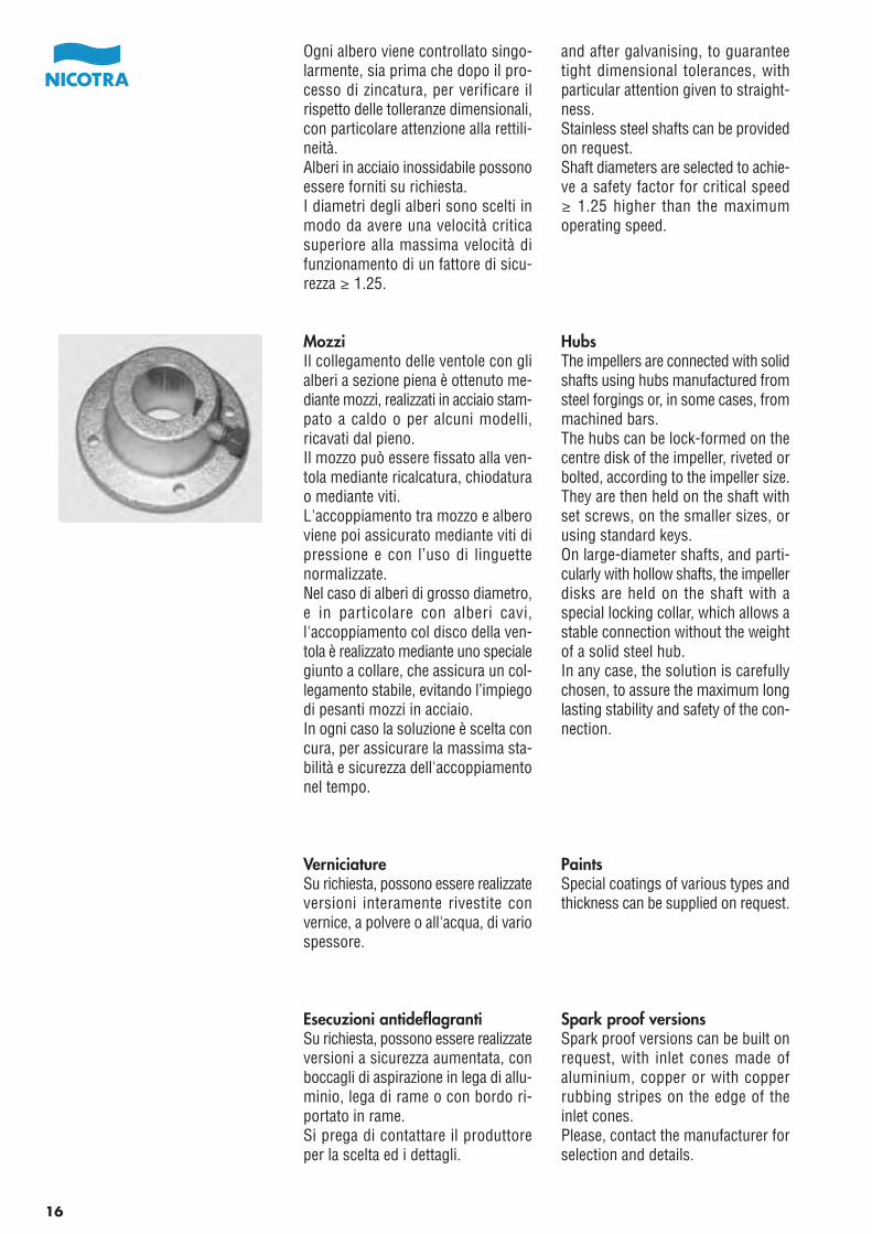
MozziIl collegamento delle ventole con glialberi a sezione piena è ottenuto me-diante mozzi, realizzati in acciaio stam-pato a caldo o per alcuni modelli,ricavati dal pieno.Il mozzo può essere fissato alla ven-tola mediante ricalcatura, chiodaturao mediante viti.L'accoppiamento tra mozzo e alberoviene poi assicurato mediante viti dipressione e con l’uso di linguettenormalizzate.Nel caso di alberi di grosso diametro,e in particolare con alberi cavi,l'accoppiamento col disco della ven-tola è realizzato mediante uno specialegiunto a collare, che assicura un col-legamento stabile, evitando l’impiegodi pesanti mozzi in acciaio.In ogni caso la soluzione è scelta concura, per assicurare la massima sta-bilità e sicurezza dell'accoppiamentonel tempo.
VerniciatureSu richiesta, possono essere realizzateversioni interamente rivestite convernice, a polvere o all'acqua, di variospessore.
Esecuzioni antideflagrantiSu richiesta, possono essere realizzateversioni a sicurezza aumentata, conboccagli di aspirazione in lega di allu-minio, lega di rame o con bordo ri-portato in rame.Si prega di contattare il produttoreper la scelta ed i dettagli.
and after galvanising, to guaranteetight dimensional tolerances, withparticular attention given to straight-ness.Stainless steel shafts can be providedon request.Shaft diameters are selected to achie-ve a safety factor for critical speed≥ 1.25 higher than the maximumoperating speed.
HubsThe impellers are connected with solidshafts using hubs manufactured fromsteel forgings or, in some cases, frommachined bars.The hubs can be lock-formed on thecentre disk of the impeller, riveted orbolted, according to the impeller size.They are then held on the shaft withset screws, on the smaller sizes, orusing standard keys.On large-diameter shafts, and parti-cularly with hollow shafts, the impellerdisks are held on the shaft with aspecial locking collar, which allows astable connection without the weightof a solid steel hub.In any case, the solution is carefullychosen, to assure the maximum longlasting stability and safety of the con-nection.
PaintsSpecial coatings of various types andthickness can be supplied on request.
Spark proof versionsSpark proof versions can be built onrequest, with inlet cones made ofaluminium, copper or with copperrubbing stripes on the edge of theinlet cones.Please, contact the manufacturer forselection and details.
16
barer Lack angebracht wird.Jede Welle wird einzeln einer Kontrolleunterzogen, sowohl vor als auch nachder Verzinkung, um so eine Kontrolleüber die Abmessungstoleranzen, be-sonders die Geradlinigkeit zu haben.A u f A n f r a g e k ö n n e n a u c hEdelstahlwellen geliefert werden.Die Wellendurchmesser werden sogewählt, dass sich für die kritischeDrehzahl ein Sicherheitsfaktor von≥ 1.25 im Vergleich zur höchstzuläs-sigen Betriebsdrehzahl ergibt.
NabenDie Verbindung zwischen Laufrad undWelle bei Vollwellen erfolgt durchNaben aus warmgepresstem Stahl;bei einigen Modellen werden dieseaus der Vollwelle selbst herausgear-beitet.Die Nabe wird an das Laufrad genietetoder verschraubt.Die Verbindung Nabe-Welle erfolgtdurch Pressschrauben und unterAnwendung von genormten Passfe-dern.Bei großen Wellendurchmessern, vorallem bei Hohlwellen, erfolgt die Ver-bindung zur Laufradscheibe mittelseines speziellen Rings, wodurch dieVerbindung stabil gehalten werdenkann und so von schweren Stahlna-ben abgesehen werden kann.In jedem Fall muss darauf ein beson-deres Augenmerk gelegt werden, da-mit Stabilität und Sicherheit über dieZeit gewährleistet werden können.
AnstrichAuf Anfrage kann der Ventilator kom-plett angestrichen geliefert werden,als Pulver- oder Wasserlackierungund in verschiedener Beschichtungs-dicke.
BrandschutztypenAuf Anfrage können Ausführungenmit höheren Sicherheitsstufen gelie-fert werden, mit Einströmdüsen inAluminiumlegierung, Kupferlegierun-gen oder mit Kupferrand.Hiefür wird gebeten den Hersteller zukontaktieren.
facilement enlevé.Chaque arbre est contrôlé avant etaprès la galvanisation, afin de garantirun respect parfait des tolérances di-mensionnelles, avec une attentionparticulière sur la droitesse.Des arbres en acier inox peuvent êtrefournis sur demande.Les diamètres des arbres sont choisisde façon à obtenir une vitesse critiquesupérieure de ≥ 1.25 à la vitessemaximum de fonctionnement.
MoyeuxLa liaison turbine-arbre plein est obte-nue au moyen d’un moyeu realisédans un alliage d’acier forgé et dansquelques cas dans des barres usinées.Le moyeu est fixé sur le disque centralde la turbine par rivetage ou boulon-nage selon les tailles de turbine. Laliaison moyeu-arbre est assurée pardes vis de serrage sur les plus petitestailles, ou avec des clefs standards.Sur les arbres de gros diamètre et enparticulier sur les arbres creux, laliaison arbre-moyeu est assurée parun collier spécial en acier, qui assureune liaison parfaite, en evitantl'utilisation de lourds moyeux en acier.En tout cas, la solution est choisieavec attention, pour assurer le maxi-mum de stabilité et de sécurité ducouplage dans le temps.
RevêtementsSur demande nous pouvons réaliserdes versions entièrement revêtuesavec peinture à poudre ou à l'eaudans différentes épaisseurs.
Exécutions antidéflagrantesSur demande, nous pouvons réaliserdes versions à sécurité augmentéeavec des ouïes d'aspiration en alliaged'aluminium, alliage de cuivre ou àbord rapporté en cuivre.Nous contacter pour sélection et de-scription.
desprender con facilidad.Cada eje se controla cuidadosamente,antes y después del proceso de cin-cado, para garantizar el respeto a lastolerancias dimensiónales, con parti-cular atención a la alineación.Bajo pedido pueden suministrarseejes en acero inoxidable.Los diámetros de los ejes se selec-cionan para tener una velocidad críticasuperior a la máxima velocidad defuncionamiento con un factor de se-guridad ≥ 1.25.
NúcleosLa unión de los rodetes a los ejesmacizos se obtiene mediante núcleos,realizados en acero forjado en calienteo, para algunos modelos, mecaniza-dos de acero.El núcleo puede ser fijado al rodetemediante embutición, remachado omediante tornillos.La unión entre núcleo y eje se aseguraposteriormente mediante tornillos depresión con el uso de chavetas nor-malizadas.En los ejes de gran diámetro, y parti-cularmente con ejes huecos, la unióncon el disco del rodete se realizamediante una junta especial con collar,que asegura una unión estable, evi-tando el uso de núcleos pesados enacero. En cada caso la solución eselegida con cuidado, para asegurar lamáxima estabilidad y seguridad delacoplamiento en el tiempo.
PinturasBajo pedido pueden realizarse versio-nes enteramente revestidas con pin-tura, a polvo o al agua, de diversoespesor.
Ejecuciones antideflagrantesBajo pedido, se pueden fabricar versionescon seguridad aumentada, con oídos deaspiración de aluminio, oídos de aspira-ción de cobre o con anillo bordeado encobre en los oídos de aspiración.Por favor, póngase en contacto con elfabricante para la selección y los detalles.
17
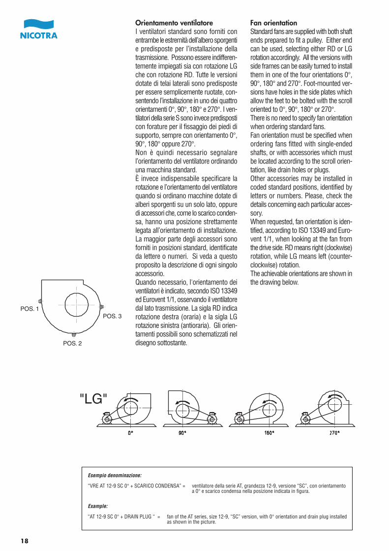
Orientamento ventilatoreI ventilatori standard sono forniti conentrambe le estremità dell’albero sporgentie predisposte per l’installazione dellatrasmissione. Possono essere indifferen-temente impiegati sia con rotazione LGche con rotazione RD. Tutte le versionidotate di telai laterali sono predisposteper essere semplicemente ruotate, con-sentendo l’installazione in uno dei quattroorientamenti 0°, 90°, 180° e 270°. I ven-tilatori della serie S sono invece predisposticon forature per il fissaggio dei piedi disupporto, sempre con orientamento 0°,90°, 180° oppure 270°.Non è quindi necessario segnalarel’orientamento del ventilatore ordinandouna macchina standard.È invece indispensabile specificare larotazione e l’orientamento del ventilatorequando si ordinano macchine dotate dialberi sporgenti su un solo lato, oppuredi accessori che, come lo scarico conden-sa, hanno una posizione strettamentelegata all’orientamento di installazione.La maggior parte degli accessori sonoforniti in posizioni standard, identificateda lettere o numeri. Si veda a questoproposito la descrizione di ogni singoloaccessorio.Quando necessario, l'orientamento deiventilatori è indicato, secondo ISO 13349ed Eurovent 1/1, osservando il ventilatoredal lato trasmissione. La sigla RD indicarotazione destra (oraria) e la sigla LGrotazione sinistra (antioraria). Gli orien-tamenti possibili sono schematizzati neldisegno sottostante.
Fan orientationStandard fans are supplied with both shaftends prepared to fit a pulley. Either endcan be used, selecting either RD or LGrotation accordingly. All the versions withside frames can be easily turned to installthem in one of the four orientations 0°,90°, 180° and 270°. Foot-mounted ver-sions have holes in the side plates whichallow the feet to be bolted with the scrolloriented to 0°, 90°, 180° or 270°.There is no need to specify fan orientationwhen ordering standard fans.Fan orientation must be specified whenordering fans fitted with single-endedshafts, or with accessories which mustbe located according to the scroll orien-tation, like drain holes or plugs.Other accessories may be installed incoded standard positions, identified byletters or numbers. Please, check thedetails concerning each particular acces-sory.When requested, fan orientation is iden-tified, according to ISO 13349 and Euro-vent 1/1, when looking at the fan fromthe drive side. RD means right (clockwise)rotation, while LG means left (counter-clockwise) rotation.The achievable orientations are shown inthe drawing below.
POS. 2
POS. 1POS. 3
Esempio denominazione:
“VRE AT 12-9 SC 0° + SCARICO CONDENSA” = ventilatore della serie AT, grandezza 12-9, versione “SC”, con orientamentoa 0° e scarico condensa nella posizione indicata in figura.
Example:
“AT 12-9 SC 0° + DRAIN PLUG “ = fan of the AT series, size 12-9, “SC” version, with 0° orientation and drain plug installedas shown in the picture.
"LG"
18
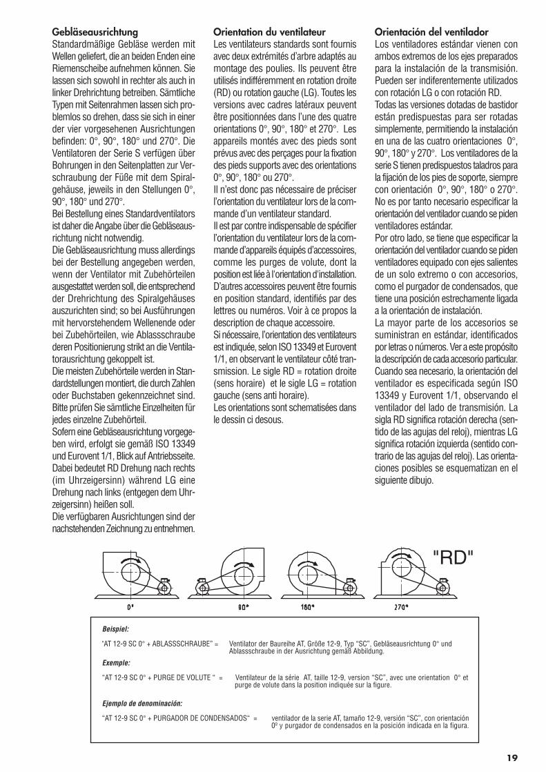
GebläseausrichtungStandardmäßige Gebläse werden mitWellen geliefert, die an beiden Enden eineRiemenscheibe aufnehmen können. Sielassen sich sowohl in rechter als auch inlinker Drehrichtung betreiben. SämtlicheTypen mit Seitenrahmen lassen sich pro-blemlos so drehen, dass sie sich in einerder vier vorgesehenen Ausrichtungenbefinden: 0°, 90°, 180° und 270°. DieVentilatoren der Serie S verfügen überBohrungen in den Seitenplatten zur Ver-schraubung der Füße mit dem Spiral-gehäuse, jeweils in den Stellungen 0°,90°, 180° und 270°.Bei Bestellung eines Standardventilatorsist daher die Angabe über die Gebläseaus-richtung nicht notwendig.Die Gebläseausrichtung muss allerdingsbei der Bestellung angegeben werden,wenn der Ventilator mit Zubehörteilenausgestattet werden soll, die entsprechendder Drehrichtung des Spiralgehäusesauszurichten sind; so bei Ausführungenmit hervorstehendem Wellenende oderbei Zubehörteilen, wie Ablassschraubederen Positionierung strikt an die Ventila-torausrichtung gekoppelt ist.Die meisten Zubehörteile werden in Stan-dardstellungen montiert, die durch Zahlenoder Buchstaben gekennzeichnet sind.Bitte prüfen Sie sämtliche Einzelheiten fürjedes einzelne Zubehörteil.Sofern eine Gebläseausrichtung vorgege-ben wird, erfolgt sie gemäß ISO 13349und Eurovent 1/1, Blick auf Antriebsseite.Dabei bedeutet RD Drehung nach rechts(im Uhrzeigersinn) während LG eineDrehung nach links (entgegen dem Uhr-zeigersinn) heißen soll.Die verfügbaren Ausrichtungen sind dernachstehenden Zeichnung zu entnehmen.
Orientation du ventilateurLes ventilateurs standards sont fournisavec deux extrémités d’arbre adaptés aumontage des poulies. Ils peuvent êtreutilisés indifféremment en rotation droite(RD) ou rotation gauche (LG). Toutes lesversions avec cadres latéraux peuventêtre positionnées dans l’une des quatreorientations 0°, 90°, 180° et 270°. Lesappareils montés avec des pieds sontprévus avec des perçages pour la fixationdes pieds supports avec des orientations0°, 90°, 180° ou 270°.Il n’est donc pas nécessaire de préciserl’orientation du ventilateur lors de la com-mande d’un ventilateur standard.Il est par contre indispensable de spécifierl’orientation du ventilateur lors de la com-mande d’appareils équipés d’accessoires,comme les purges de volute, dont laposition est liée à l'orientation d'installation.D’autres accessoires peuvent être fournisen position standard, identifiés par deslettres ou numéros. Voir à ce propos ladescription de chaque accessoire.Si nécessaire, l’orientation des ventilateursest indiquée, selon ISO 13349 et Eurovent1/1, en observant le ventilateur côté tran-smission. Le sigle RD = rotation droite(sens horaire) et le sigle LG = rotationgauche (sens anti horaire).Les orientations sont schematisées dansle dessin ci desous.
Orientación del ventiladorLos ventiladores estándar vienen conambos extremos de los ejes preparadospara la instalación de la transmisión.Pueden ser indiferentemente utilizadoscon rotación LG o con rotación RD.Todas las versiones dotadas de bastidorestán predispuestas para ser rotadassimplemente, permitiendo la instalaciónen una de las cuatro orientaciones 0°,90°, 180° y 270°. Los ventiladores de laserie S tienen predispuestos taladros parala fijación de los pies de soporte, siemprecon orientación 0°, 90°, 180° o 270°.No es por tanto necesario especificar laorientación del ventilador cuando se pidenventiladores estándar.Por otro lado, se tiene que especificar laorientación del ventilador cuando se pidenventiladores equipado con ejes salientesde un solo extremo o con accesorios,como el purgador de condensados, quetiene una posición estrechamente ligadaa la orientación de instalación.La mayor parte de los accesorios sesuministran en estándar, identificadospor letras o números. Ver a este propósitola descripción de cada accesorio particular.Cuando sea necesario, la orientación delventilador es especificada según ISO13349 y Eurovent 1/1, observando elventilador del lado de transmisión. Lasigla RD significa rotación derecha (sen-tido de las agujas del reloj), mientras LGsignifica rotación izquierda (sentido con-trario de las agujas del reloj). Las orienta-ciones posibles se esquematizan en elsiguiente dibujo.
"RD"
Beispiel:
"AT 12-9 SC 0° + ABLASSSCHRAUBE” = Ventilator der Baureihe AT, Größe 12-9, Typ “SC”, Gebläseausrichtung 0° undAblassschraube in der Ausrichtung gemäß Abbildung.
Exemple:
“AT 12-9 SC 0° + PURGE DE VOLUTE “ = Ventilateur de la série AT, taille 12-9, version “SC”, avec une orientation 0° etpurge de volute dans la position indiquée sur la figure.
Ejemplo de denominación:
“AT 12-9 SC 0° + PURGADOR DE CONDENSADOS“ = ventilador de la serie AT, tamaño 12-9, versión “SC”, con orientación0º y purgador de condensados en la posición indicada en la figura.
19
MontaggioOgni ventilatore viene fornito collau-dato e pronto al montaggio.I supporti base delle versioni S e G2Lnon sono normalmente forniti insiemecon il ventilatore standard, e devonoessere ordinati separatamente comeaccessorio. Il kit, composto da duesupporti base, comprende anche leviti di fissaggio e i gommini antivi-branti per l’attacco al basamento.I ventilatori dotati di telai laterali,singoli, binati o trinati, non abbiso-gnano di alcun accessorio, in quantoi telai sono già predisposti con oppor-tune forature ad asola per il fissaggionei 4 orientamenti della bocca di man-data.È sempre sconsigliabile il montaggiodi un qualsiasi ventilatore di tipo stan-dard con l'asse in posizione verticale.Per questo tipo di applicazioni, siprega di contattare il produttore.Il motore può essere fissato diretta-mente sulla coclea dei ventilatori inversione S, mediante apposite staffedi supporto che devono essere ordi-nate a parte; il kit di montaggio fornitoda Nicotra comprende tutti i compo-nenti necessari al montaggio del mo-tore e al tensionamento delle cinghie.Per ulteriori informazioni vedere apag. 78.
InstallationEach fan, as supplied, is ready forinstallation.Base feet for S and G2L versions arenormally not supplied with the basicblower, and must be ordered separa-tely as an accessory. A mounting feetkit is made of two, opposed base feet,and includes the mounting screwsand four vibration insulators whichfit into the holes of the feet.The fans equipped with side-framesdo not need additional accessoriesfor mounting, as the frames have apair of holes on each side, for boltingthe fan on to the base frame, in eachone of the four possible orientations.Standard fans should never be instal-led with their shaft vertical. For thiskind of special application, pleasecontact the manufacturer.Motors can be fixed directly on thescroll of the S-version fans, usingspecially-designed motor brackets,to be ordered separately; the moun-ting kit, as supplied by Nicotra, con-tains all the components required tofix the motor and tension the beltdrive. For additional information,please look at page 78.
20
MontageJeder Venti lator wurde einerLeistungsprüfung unterzogen.Die Stützfüße der Versionen S undG2L werden normalerweise nicht zu-sammen mit dem Standardventilatorgeliefert und müssen somit separatals Zubehörteil geordert werden. DasKit besteht aus zwei Stützfüßen mitBefestigungsschrauben und Gummi-schwingungsdämpfer, die an dieGrundplatte angeracht werden.Die Ventilatoren mit Seitenrahmen,in Einfach-Zwillings- oder Drillingsver-sion benötigen kein Zubehörteil, dadie Seitenrahmen bereits überÖsenbohrungen zur Anbringung desAusblaßes in den 4 angegebenen Aus-richtungen verfügen.Es wird grundsätzlich davon abgeratenden Standardventilator in Vertikalachseanzubringen. In diesem Fall bitte vorherden Hersteller konsultieren.Motoren können mit speziellenMotorhaltebügeln direkt auf den Ven-tilator montiert werden (S–Version).Nicotra liefert in einem Montagekitalle Teile die zum Motoraufbau erfor-derlich sind.Für weitere Informationen – sieheSeite 78 .
Installation des ventilateurs.Chaque ventilateur est livré prêt aumontage.Les pieds support des version S etG2L ne sont pas livrés sur la versionde base, ils font partie des accessoiresà commander séparément. Le jeu depieds support comprend deux pieds,la visserie de montage et les caou-tchouc antivibratoires.Les ventilateurs équipés de cadreslatéraux, en version simple, doubleou triple, n’ont nullement besoind’accessoires puisqu’ils peuvent êtrefixés en utilisant le châssis existantdans chacune des quatre orientations.Les ventilateurs standards ne peuventêtre installés avec leur arbre en posi-tionnement vertical. Pour cette appli-cation spéciale prendre contact avecle constructeur.Le moteur peut être fixé directementà la volute des ventilateurs en versionS, avec des supports à commanderséparément; le kit de montage fournipar Nicotra comprend tous les acces-soires nécessaires au montage dumoteur et au tensionnement des cour-roies.Pour plus de détails, se reporter auchapitre de la page 78.
Instalación del ventiladorCada ventilador se suministra listopara el montaje.Los soportes base de las versionesS y G2L no se suministran normal-mente con el ventilador estándar, ydeben ser pedidos separadamentecomo accesorio. El kit, compuestode dos soportes base, incluye tambiénlos tornillos de fijación y las gomasamortiguadoras para la unión a labase.Los ventiladores equipados con ba-stidores laterales, simples, dobles otriples, no necesitan ningún accesorioya que vienen predispuestos con ta-ladros ovalados apropiados para lafijación en las 4 orientaciones de laboca de impulsión.Es desaconsejable el montaje de cual-quier ventilador estándar con su ejeen vertical. Póngase en contacto conel fabricante para este tipo de uso.El motor puede ser fijado directamen-te sobre la voluta en las versiones S,mediante soportes de motor que de-ben ser perdidos a parte; el kit demontaje suministrado por Nicotraincluye todos los componentes nece-sarios para el montaje del motor y eltensado de las correas. Para masinformación consultar la pág. 78.
21
CARATTERISTICHE DIFUNZIONAMENTO
Prestazioni aeraulicheLe prestazioni dei ventilatori indicatesul presente catalogo, sono riferite alfunzionamento in installazione “B”,con aspirazione libera e bocca di man-data canalizzata. Tali prestazioni sonostate calcolate a partire da prove svoltepresso il laboratorio Nicotra, in accordocon le norme AMCA 210-99 (fig. 12),UNI 10531 (fig. 30 c e par. 29.2 f) edISO 5801 (fig. 69 c e par. 30.2 f).Le prestazioni sono riferite ad unadensità standard dell ’aria di1.20 kg/m3.Le scale della pressione dinamica con-venzionale e della velocità d'uscitadell'aria, tracciate sotto ciascun dia-gramma, sono calcolate secondo lenorme citate, facendo riferimentoall’area totale della bocca di mandata.
Funzionamento “a bocca libera”Nel funzionamento in installazione“A”, con aspirazione e bocca di man-data non canalizzate, la pressionestatica utile del ventilatore, pSA, è piùbassa che nel funzionamento conbocca canalizzata, e può essere cal-colata, con buona approssimazione,sottraendo, alla pressione totale dicatalogo, una pressione dinamicamaggiorata, ottenuta moltiplicandola pressione dinamica normalizzataper il fattore Kd indicato nella tabellasotto riportata.Questa maggiorazione rappresental’effetto dell’aumento della pressionedinamica, provocato dallo strozza-mento del flusso ad opera del deflet-tore, e della mancanza di un canaledi mandata, che opererebbe comediffusore, permettendo di riconvertirela pressione dinamica eccedente inpressione statica.Le prestazioni così calcolate non sonocertificate AMCA.
PERFORMANCE SPECIFICATIONS
Air performanceAir performance ratings of the fansdescribed by this catalogue have beenderived from performance tests madewith installation type “B”, with freeinlet and ducted outlet. These testswere carried out in the Nicotra labo-ratory, in accordance with the fol-lowing standards: AMCA 210-99 (Fig.12), UNI 10531 (Fig. 30 c and par.29.2 f) and ISO 5801 (Fig. 69 c andpar. 30.2 f).Ratings are referred to the standardair density of 1.20 kg/m3.Dynamic pressure and outlet air ve-locity, as shown on the scales beloweach diagram, are calculated in accor-dance with the said standards, usingthe total outlet area for calculationpurposes.
“Free-outlet” operationWhen operating in installation type“A”, with free inlet and free outlet, theavailable static pressure of the fan,pSA, is lower than when the fan is used with ducted outlet, and can besatisfactorily calculated subtracting,from the total pressure shown in thecatalogue, an increased dynamic pres-sure, calculated by multiplying con-ventional dynamic pressure by afactor Kd shown below.This dynamic pressure increase re-presents the effect of the airflow con-traction produced by the cut-off plateand the absence of an outlet duct,which would act as a diffuser, allowingat least partial conversion of theexcess of dynamic pressure into staticpressure.Fan performance so calculated is notAMCA Licensed.
22
LEISTUNGSSPEZIFIKATIONEN
LuftdurchsatzDie Luftdurchsatzwerte für die in die-sem Katalog bezeichneten Gebläsewurden jewei ls anhand vonLeistungsprüfungen mit einer Anlagevom Typ “B" ermittelt, welche übereinen Zulauf ohne und einen Ablaufmit Luftführung erfolgt. DiesePrüfungen wurden im Firmenlaborbei Nicotra ausgeführt und zwar nachMaßgabe der folgenden Normen:AMCA 210-99 (Abb. 12), UNI 10531(Abb. 30 c und §. 29.2 f) und ISO5801 (Abb. 69 c und § 30.2 f).Alle Werte beziehen sich auf die Nor-mluftdichte von 1,20 kg/m3.Staudruck und Abluftgeschwindigkeitwerden gemäß den Maßstäben unterden einzelnen Diagrammen in Übe-reinstimmung mit den genannten Nor-men ermittelt, wobei die gesamteAuslassfläche für die Berechnungenherangezogen wird.
Betrieb ohne Luftführung am AuslassWenn eine Anlage des Typs "A" ge-fahren wird, d.h. ohne Luftführungam Ein- und Auslass, liegt derverfügbare statische Druck des Ge-bläses, pSA, unter dem Wert für denBetrieb mit Luftführung am Auslass;die Berechnung lässt sich problemlosdurch Subtraktion des entsprechendangehobenen Staudrucks vom Ge-samtdruckwert laut Katalog ermitteln,wobei die Erhöhung laut Multiplikationdes üblichen Staudrucks um den na-chstehend dargestellten Faktor Kd
erfolgt.Der Anstieg des Staudrucks entsprichtden Auswirkungen der Strömungsve-rengung durch den Sperrschieber undden Auslass ohne Luftführung, derals Diffusor wirken würde, sodasszumindest eine Teilumwandlung desüberschüssigen Staudrucks in stati-schen Druck stattfinden könnte.Für die Messung von Gebläseleistun-gen nach diesem Verfahren liegt keineAMCA Lizenz vor.
CARACTÉRISTIQUES DEFONCTIONNEMENT
Performances aérauliquesLes performances des ventilateursprésentés dans ce catalogue fontréférence au fonctionnement en utili-sation "B" avec aspiration libre et bou-che canalisée. Ces performances ontété calculées à partir d’essais réalisésdans le laboratoire Nicotra conformé-ment aux normes AMCA 210-99(fig.12), UNI 10531 (fig.30 c et par.29.2 f) et ISO 5801 (fig.69 c et par.30.2 f).Les performances se réfèrent à unedensité standard de l ’air de1.20 kg/m3.Les échelles de la pression dynamiqueconventionnelle et de la vitesse desortie d’air, tracées sous chaque dia-gramme sont calculées suivant desnormes et en faisant référence à lasurface totale de la bouche de refou-lement.
Fonctionnement "bouche bée"Dans le fonctionnement en utilisation“A” avec aspiration et bouche de re-foulement non canalisées, la pressionstatique utile du ventilateur, pSA, estplus basse qu’en cas de fonctionne-ment en bouche canalisée, elle peutêtre calculée, avec une bonne appro-ximation, en soustrayant de la pres-sion totale du catalogue une pressiondynamique obtenue en multipliant lapression dynamique normalisée parle facteur Kd du tableau ci-dessous.Cette augmentation représente l’effetde l’accroissement de la pressiondynamique provoqué par la contrac-tion du flux causé par le déflecteur etpar l’absence de gaine au refoulementqui opèrerait comme diffuseur enpermettant de reconvertir la pressiondynamique excédentaire en pressionstatique.Les performances ainsi calculées nesont pas certifiées AMCA.
CARACTERÍSTICAS DEFUNCIONAMIENTO
Prestaciones aerólicasLas prestaciones aerólicas indicadasen el presente catálogo, están referi-das al funcionamiento en instalación“B”, con aspiración libre y boca deimpulsión canalizada. Tales prestacio-nes han sido calculadas a partir depruebas realizadas en el laboratorioNicotra, de acuerdo con las normasAMCA 210-99 (Fig. 12), UNI 10531(Fig. 30 c y par. 29.2 f) e ISO 5801(Fig. 69 c y par. 30.2 f).Las prestaciones se refieren a unadensidad de aire estándar de1.20 kg/m3.Las escalas de la presión dinámicaconvencional y de la velocidad desalida del aire, mostradas en la parteinferior de cada diagrama, se calculansegún las normas citadas, haciendoreferencia al área total de la boca deimpulsión.
Funcionamiento “a boca libre“En el funcionamiento en instalacionestipo “A” con aspiración y salida nocanalizadas, la presión estática dispo-nible del ventilador, pSA , es mas bajaque en el funcionamiento con bocacanalizada, y puede ser calculada,con buena aproximación, restando ala presión total de catálogo, una pre-sión dinámica incrementada, calcula-da multiplicando la presión dinámicaconvencional por el factor Kd indicadoen la tabla abajo mostrada.Este incremento representa el efectodel aumento de la presión dinámica,provocado por el estrangulamientodel flujo del aire por parte del deflectory la ausencia de un conducto en im-pulsión, que actuaría como difusor,permitiendo reconvertir la presióndinámica excedente en presión estáti-ca.Las prestaciones así calculadas noestán certificadas AMCA.
23
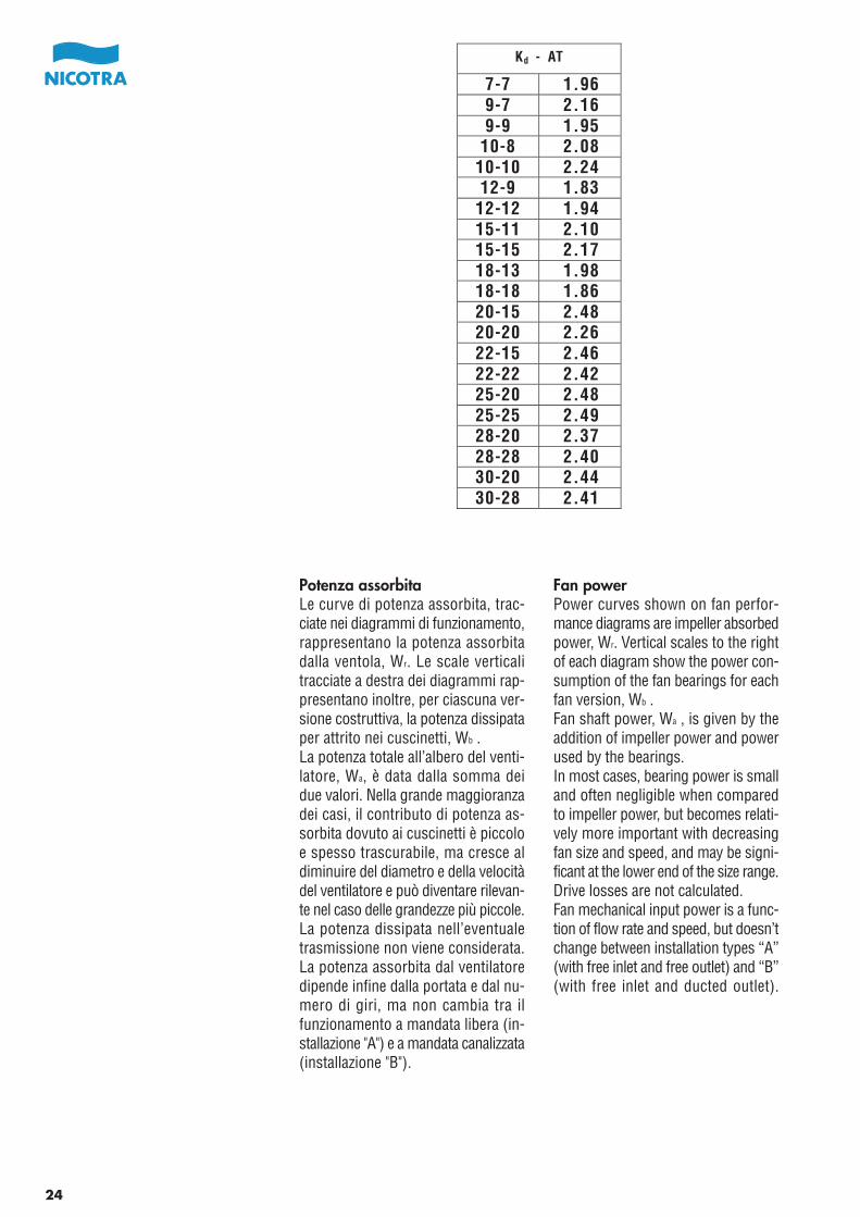
Potenza assorbitaLe curve di potenza assorbita, trac-ciate nei diagrammi di funzionamento,rappresentano la potenza assorbitadalla ventola, Wr. Le scale verticalitracciate a destra dei diagrammi rap-presentano inoltre, per ciascuna ver-sione costruttiva, la potenza dissipataper attrito nei cuscinetti, Wb .La potenza totale all’albero del venti-latore, Wa, è data dalla somma deidue valori. Nella grande maggioranzadei casi, il contributo di potenza as-sorbita dovuto ai cuscinetti è piccoloe spesso trascurabile, ma cresce aldiminuire del diametro e della velocitàdel ventilatore e può diventare rilevan-te nel caso delle grandezze più piccole.La potenza dissipata nell’eventualetrasmissione non viene considerata.La potenza assorbita dal ventilatoredipende infine dalla portata e dal nu-mero di giri, ma non cambia tra ilfunzionamento a mandata libera (in-stallazione "A") e a mandata canalizzata(installazione "B").
Fan powerPower curves shown on fan perfor-mance diagrams are impeller absorbedpower, Wr. Vertical scales to the rightof each diagram show the power con-sumption of the fan bearings for eachfan version, Wb .Fan shaft power, Wa , is given by theaddition of impeller power and powerused by the bearings.In most cases, bearing power is smalland often negligible when comparedto impeller power, but becomes relati-vely more important with decreasingfan size and speed, and may be signi-ficant at the lower end of the size range.Drive losses are not calculated.Fan mechanical input power is a func-tion of flow rate and speed, but doesn’tchange between installation types “A”(with free inlet and free outlet) and “B”(with free inlet and ducted outlet).
Kd - AT
7-7 1.969-7 2.169-9 1.95
10-8 2.0810-10 2.2412-9 1.83
12-12 1.9415-11 2.1015-15 2.1718-13 1.9818-18 1.8620-15 2.4820-20 2.2622-15 2.4622-22 2.4225-20 2.4825-25 2.4928-20 2.3728-28 2.4030-20 2.4430-28 2.41
24
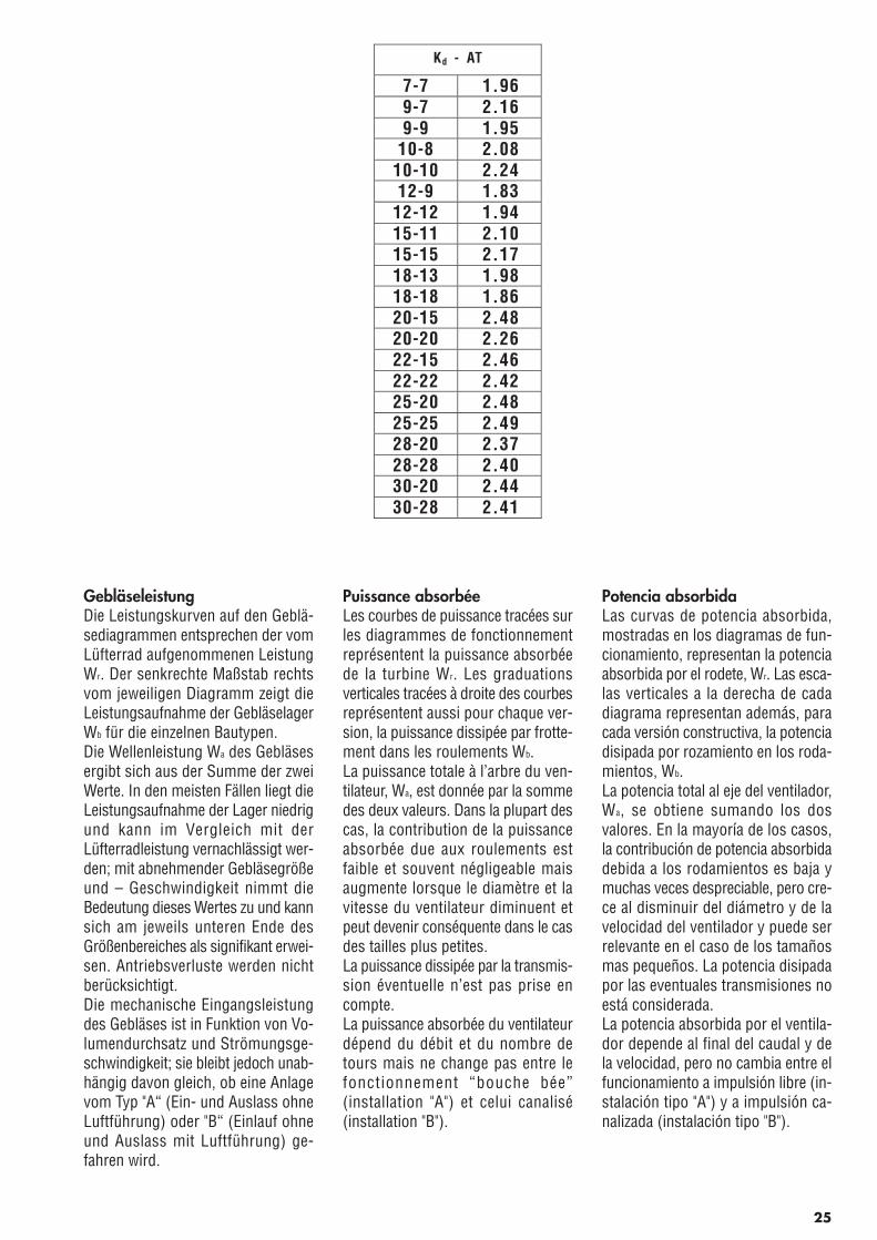
GebläseleistungDie Leistungskurven auf den Geblä-sediagrammen entsprechen der vomLüfterrad aufgenommenen LeistungWr. Der senkrechte Maßstab rechtsvom jeweiligen Diagramm zeigt dieLeistungsaufnahme der GebläselagerWb für die einzelnen Bautypen.Die Wellenleistung Wa des Gebläsesergibt sich aus der Summe der zweiWerte. In den meisten Fällen liegt dieLeistungsaufnahme der Lager niedrigund kann im Vergleich mit derLüfterradleistung vernachlässigt wer-den; mit abnehmender Gebläsegrößeund – Geschwindigkeit nimmt dieBedeutung dieses Wertes zu und kannsich am jeweils unteren Ende desGrößenbereiches als signifikant erwei-sen. Antriebsverluste werden nichtberücksichtigt.Die mechanische Eingangsleistungdes Gebläses ist in Funktion von Vo-lumendurchsatz und Strömungsge-schwindigkeit; sie bleibt jedoch unab-hängig davon gleich, ob eine Anlagevom Typ "A“ (Ein- und Auslass ohneLuftführung) oder "B“ (Einlauf ohneund Auslass mit Luftführung) ge-fahren wird.
Puissance absorbéeLes courbes de puissance tracées surles diagrammes de fonctionnementreprésentent la puissance absorbéede la turbine Wr. Les graduationsverticales tracées à droite des courbesreprésentent aussi pour chaque ver-sion, la puissance dissipée par frotte-ment dans les roulements Wb.La puissance totale à l’arbre du ven-tilateur, Wa, est donnée par la sommedes deux valeurs. Dans la plupart descas, la contribution de la puissanceabsorbée due aux roulements estfaible et souvent négligeable maisaugmente lorsque le diamètre et lavitesse du ventilateur diminuent etpeut devenir conséquente dans le casdes tailles plus petites.La puissance dissipée par la transmis-sion éventuelle n’est pas prise encompte.La puissance absorbée du ventilateurdépend du débit et du nombre detours mais ne change pas entre lefonctionnement “bouche bée”(installation "A") et celui canalisé(installation "B").
Potencia absorbidaLas curvas de potencia absorbida,mostradas en los diagramas de fun-cionamiento, representan la potenciaabsorbida por el rodete, Wr. Las esca-las verticales a la derecha de cadadiagrama representan además, paracada versión constructiva, la potenciadisipada por rozamiento en los roda-mientos, Wb.La potencia total al eje del ventilador,Wa, se obtiene sumando los dosvalores. En la mayoría de los casos,la contribución de potencia absorbidadebida a los rodamientos es baja ymuchas veces despreciable, pero cre-ce al disminuir del diámetro y de lavelocidad del ventilador y puede serrelevante en el caso de los tamañosmas pequeños. La potencia disipadapor las eventuales transmisiones noestá considerada.La potencia absorbida por el ventila-dor depende al final del caudal y dela velocidad, pero no cambia entre elfuncionamiento a impulsión libre (in-stalación tipo "A") y a impulsión ca-nalizada (instalación tipo "B").
Kd - AT
7-7 1.969-7 2.169-9 1.95
10-8 2.0810-10 2.2412-9 1.83
12-12 1.9415-11 2.1015-15 2.1718-13 1.9818-18 1.8620-15 2.4820-20 2.2622-15 2.4622-22 2.4225-20 2.4825-25 2.4928-20 2.3728-28 2.4030-20 2.4430-28 2.41
25
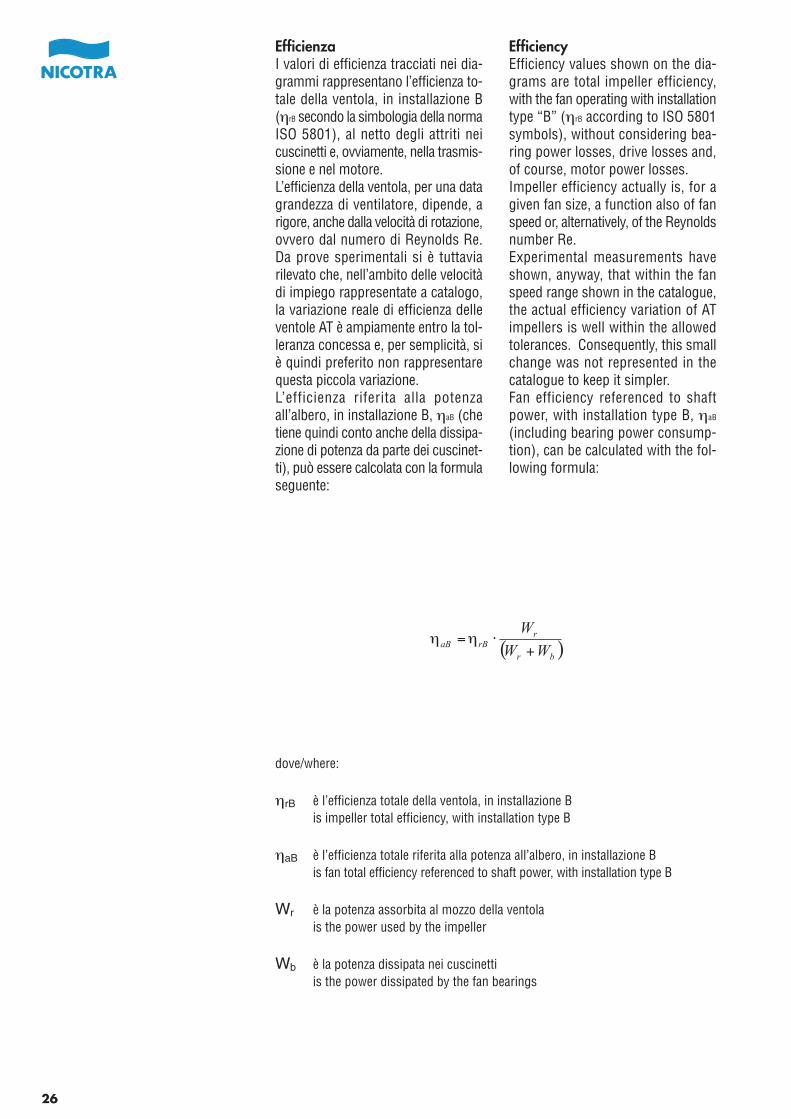
EfficienzaI valori di efficienza tracciati nei dia-grammi rappresentano l’efficienza to-tale della ventola, in installazione B(ηrB secondo la simbologia della normaISO 5801), al netto degli attriti neicuscinetti e, ovviamente, nella trasmis-sione e nel motore.L’efficienza della ventola, per una datagrandezza di ventilatore, dipende, arigore, anche dalla velocità di rotazione,ovvero dal numero di Reynolds Re.Da prove sperimentali si è tuttaviarilevato che, nell’ambito delle velocitàdi impiego rappresentate a catalogo,la variazione reale di efficienza delleventole AT è ampiamente entro la tol-leranza concessa e, per semplicità, siè quindi preferito non rappresentarequesta piccola variazione.L’efficienza riferita alla potenzaall’albero, in installazione B, ηaB (chetiene quindi conto anche della dissipa-zione di potenza da parte dei cuscinet-ti), può essere calcolata con la formulaseguente:
EfficiencyEfficiency values shown on the dia-grams are total impeller efficiency,with the fan operating with installationtype “B” (ηrB according to ISO 5801symbols), without considering bea-ring power losses, drive losses and,of course, motor power losses.Impeller efficiency actually is, for agiven fan size, a function also of fanspeed or, alternatively, of the Reynoldsnumber Re.Experimental measurements haveshown, anyway, that within the fanspeed range shown in the catalogue,the actual efficiency variation of ATimpellers is well within the allowedtolerances. Consequently, this smallchange was not represented in thecatalogue to keep it simpler.Fan efficiency referenced to shaftpower, with installation type B, ηaB
(including bearing power consump-tion), can be calculated with the fol-lowing formula:
dove/where:
ηrB è l’efficienza totale della ventola, in installazione Bis impeller total efficiency, with installation type B
ηaB è l’efficienza totale riferita alla potenza all’albero, in installazione Bis fan total efficiency referenced to shaft power, with installation type B
Wr è la potenza assorbita al mozzo della ventolais the power used by the impeller
Wb è la potenza dissipata nei cuscinettiis the power dissipated by the fan bearings
26
( )br
rrBaB WW
W
+⋅=ηη
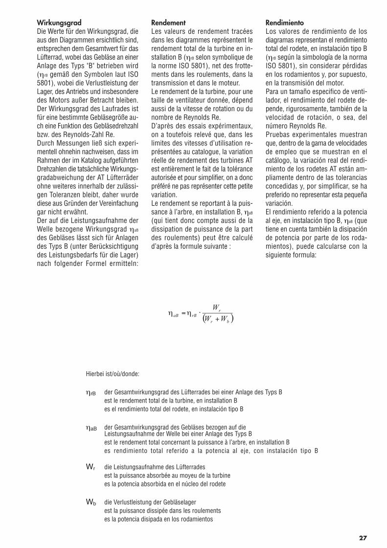
WirkungsgradDie Werte für den Wirkungsgrad, dieaus den Diagrammen ersichtlich sind,entsprechen dem Gesamtwert für dasLüfterrad, wobei das Gebläse an einerAnlage des Typs "B" betrieben wird(ηrB gemäß den Symbolen laut ISO5801), wobei die Verlustleistung derLager, des Antriebs und insbesonderedes Motors außer Betracht bleiben.Der Wirkungsgrad des Laufrades istfür eine bestimmte Gebläsegröße au-ch eine Funktion des Gebläsedrehzahlbzw. des Reynolds-Zahl Re.Durch Messungen ließ sich experi-mentell ohnehin nachweisen, dass imRahmen der im Katalog aufgeführtenDrehzahlen die tatsächliche Wirkungs-gradabweichung der AT Lüfterräderohne weiteres innerhalb der zulässi-gen Toleranzen bleibt, daher wurdediese aus Gründen der Vereinfachunggar nicht erwähnt.Der auf die Leistungsaufnahme derWelle bezogene Wirkungsgrad ηaB
des Gebläses lässt sich für Anlagendes Typs B (unter Berücksichtigungdes Leistungsbedarfs für die Lager)nach folgender Formel ermitteln:
RendementLes valeurs de rendement tracéesdans les diagrammes représentent lerendement total de la turbine en in-stallation B (ηrB selon symbolique dela norme ISO 5801), net des frotte-ments dans les roulements, dans latransmission et dans le moteur.Le rendement de la turbine, pour unetaille de ventilateur donnée, dépendaussi de la vitesse de rotation ou dunombre de Reynolds Re.D’après des essais expérimentaux,on a toutefois relevé que, dans leslimites des vitesses d’utilisation re-présentées au catalogue, la variationréelle de rendement des turbines ATest entièrement le fait de la toléranceautorisée et pour simplifier, on a doncpréféré ne pas représenter cette petitevariation.Le rendement se reportant à la puis-sance à l’arbre, en installation B, ηaB
(qui tient donc compte aussi de ladissipation de puissance de la partdes roulements) peut être calculéd’après la formule suivante :
RendimientoLos valores de rendimiento de losdiagramas representan el rendimientototal del rodete, en instalación tipo B(ηrB según la simbología de la normaISO 5801), sin considerar pérdidasen los rodamientos y, por supuesto,en la transmisión del motor.Para un tamaño especifico de venti-lador, el rendimiento del rodete de-pende, rigurosamente, también de lavelocidad de rotación, o sea, delnúmero Reynolds Re.Pruebas experimentales muestranque, dentro de la gama de velocidadesde empleo que se muestran en elcatálogo, la variación real del rendi-miento de los rodetes AT están am-pliamente dentro de las toleranciasconcedidas y, por simplificar, se hapreferido no representar esta pequeñavariación.El rendimiento referido a la potenciaal eje, en instalación tipo B, ηaB (quetiene en cuenta también la disipaciónde potencia por parte de los roda-mientos), puede calcularse con lasiguiente formula:
Hierbei ist/où/donde:
ηrB der Gesamtwirkungsgrad des Lüfterrades bei einer Anlage des Typs Best le rendement total de la turbine, en installation Bes el rendimiento total del rodete, en instalación tipo B
ηaB der Gesamtwirkungsgrad des Gebläses bezogen auf die Leistungsaufnahme der Welle bei einer Anlage des Typs Best le rendement total concernant la puissance à l’arbre, en installation Bes rendimiento total referido a la potencia al eje, con instalación tipo B
Wr die Leistungsaufnahme des Lüfterradesest la puissance absorbée au moyeu de la turbinees la potencia absorbida en el núcleo del rodete
Wb die Verlustleistung der Gebläselagerest la puissance dissipée dans les roulements
es la potencia disipada en los rodamientos
27
( )br
rrBaB WW
W
+⋅=ηη
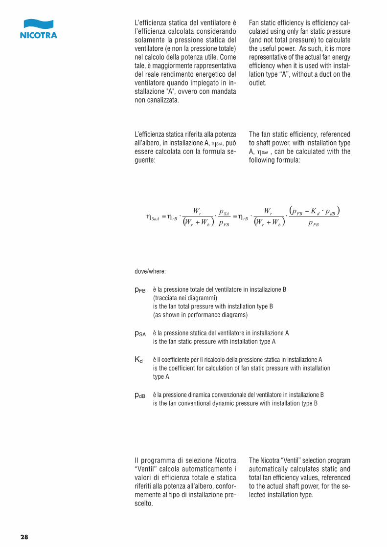
L’efficienza statica del ventilatore èl’efficienza calcolata considerandosolamente la pressione statica delventilatore (e non la pressione totale)nel calcolo della potenza utile. Cometale, è maggiormente rappresentativadel reale rendimento energetico delventilatore quando impiegato in in-stallazione "A", ovvero con mandatanon canalizzata.
L’efficienza statica riferita alla potenzaall’albero, in installazione A, ηSaA, puòessere calcolata con la formula se-guente:
Il programma di selezione Nicotra“Ventil” calcola automaticamente ivalori di efficienza totale e staticariferiti alla potenza all’albero, confor-memente al tipo di installazione pre-scelto.
Fan static efficiency is efficiency cal-culated using only fan static pressure(and not total pressure) to calculatethe useful power. As such, it is morerepresentative of the actual fan energyefficiency when it is used with instal-lation type “A”, without a duct on theoutlet.
The fan static efficiency, referencedto shaft power, with installation typeA, ηSaA , can be calculated with thefollowing formula:
The Nicotra “Ventil” selection programautomatically calculates static andtotal fan efficiency values, referencedto the actual shaft power, for the se-lected installation type.
dove/where:
pFB è la pressione totale del ventilatore in installazione B(tracciata nei diagrammi)is the fan total pressure with installation type B(as shown in performance diagrams)
pSA è la pressione statica del ventilatore in installazione Ais the fan static pressure with installation type A
Kd è il coefficiente per il ricalcolo della pressione statica in installazione Ais the coefficient for calculation of fan static pressure with installationtype A
pdB è la pressione dinamica convenzionale del ventilatore in installazione Bis the fan conventional dynamic pressure with installation type B
28
( ) ( )( )
FB
dBdFB
br
rrB
FB
SA
br
rrBSaA p
pKp
WW
W
p
p
WW
W ⋅−⋅
+⋅=⋅
+⋅= ηηη
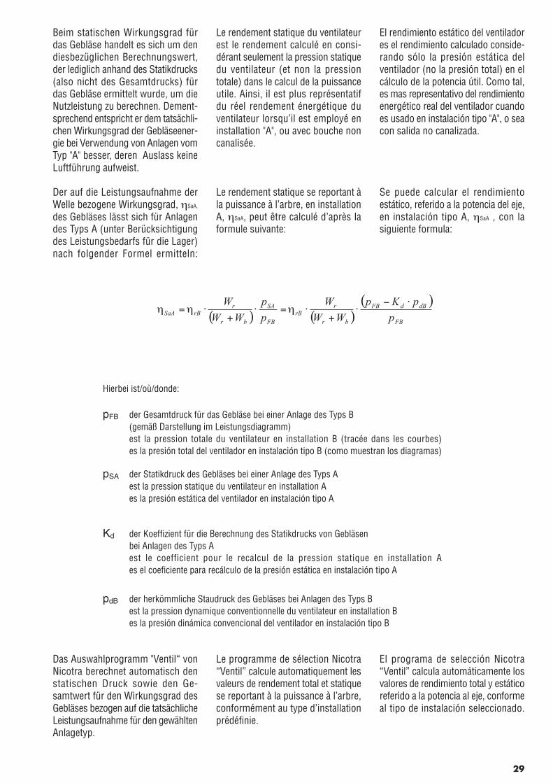
Beim statischen Wirkungsgrad fürdas Gebläse handelt es sich um dendiesbezüglichen Berechnungswert,der lediglich anhand des Statikdrucks(also nicht des Gesamtdrucks) fürdas Gebläse ermittelt wurde, um dieNutzleistung zu berechnen. Dement-sprechend entspricht er dem tatsächli-chen Wirkungsgrad der Gebläseener-gie bei Verwendung von Anlagen vomTyp "A" besser, deren Auslass keineLuftführung aufweist.
Der auf die Leistungsaufnahme derWelle bezogene Wirkungsgrad, ηSaA,
des Gebläses lässt sich für Anlagendes Typs A (unter Berücksichtigungdes Leistungsbedarfs für die Lager)nach folgender Formel ermitteln:
Das Auswahlprogramm "Ventil“ vonNicotra berechnet automatisch denstatischen Druck sowie den Ge-samtwert für den Wirkungsgrad desGebläses bezogen auf die tatsächlicheLeistungsaufnahme für den gewähltenAnlagetyp.
Le rendement statique du ventilateurest le rendement calculé en consi-dérant seulement la pression statiquedu ventilateur (et non la pressiontotale) dans le calcul de la puissanceutile. Ainsi, il est plus représentatifdu réel rendement énergétique duventilateur lorsqu’il est employé eninstallation "A", ou avec bouche noncanalisée.
Le rendement statique se reportant àla puissance à l’arbre, en installationA, ηSaA, peut être calculé d’après laformule suivante:
Le programme de sélection Nicotra“Ventil” calcule automatiquement lesvaleurs de rendement total et statiquese reportant à la puissance à l’arbre,conformément au type d’installationprédéfinie.
El rendimiento estático del ventiladores el rendimiento calculado conside-rando sólo la presión estática delventilador (no la presión total) en elcálculo de la potencia útil. Como tal,es mas representativo del rendimientoenergético real del ventilador cuandoes usado en instalación tipo "A", o seacon salida no canalizada.
Se puede calcular el rendimientoestático, referido a la potencia del eje,en instalación tipo A, ηSaA , con lasiguiente formula:
El programa de selección Nicotra“Ventil” calcula automáticamente losvalores de rendimiento total y estáticoreferido a la potencia al eje, conformeal tipo de instalación seleccionado.
Hierbei ist/où/donde:
pFB der Gesamtdruck für das Gebläse bei einer Anlage des Typs B(gemäß Darstellung im Leistungsdiagramm)est la pression totale du ventilateur en installation B (tracée dans les courbes)es la presión total del ventilador en instalación tipo B (como muestran los diagramas)
pSA der Statikdruck des Gebläses bei einer Anlage des Typs Aest la pression statique du ventilateur en installation Aes la presión estática del ventilador en instalación tipo A
Kd der Koeffizient für die Berechnung des Statikdrucks von Gebläsen bei Anlagen des Typs A
est le coefficient pour le recalcul de la pression statique en installation Aes el coeficiente para recálculo de la presión estática en instalación tipo A
pdB der herkömmliche Staudruck des Gebläses bei Anlagen des Typs Best la pression dynamique conventionnelle du ventilateur en installation Bes la presión dinámica convencional del ventilador en instalación tipo B
29
( ) ( )( )
FB
dBdFB
br
rrB
FB
SA
br
rrBSaA p
pKp
WW
W
p
p
WW
W ⋅−⋅
+⋅=⋅
+⋅= ηηη

RumorositàLa rumorosità dei ventilatori AT ècalcolata a partire da prove svolte inaccordo alla norma AMCA 300-96 econformemente alla fig. 2 (misure sullato di aspirazione) ed alla fig. 3 (mi-sure sul lato di mandata).I risultati sono stati estesi ad altrevelocità mediante il procedimento dicalcolo descritto nella norma BS 848,Parte 2, Appendice G. Tale procedi-mento è una versione perfezionatadel procedimento descritto dalla nor-ma AMCA 301-90 ed è in accordocon i documenti attualmente in corsodi elaborazione da parte del comitatotecnico ISO TC 117.Sui diagrammi, sono riportate le curvedi livello di potenza sonora pesata A(Lws7(A)) riferita al lato di aspirazionedel ventilatore.Altri parametri acustici del ventilatoresono: il livello di potenza sonora pe-sata A sul lato di mandata Lws4(A), illivello di potenza sonora di ciascunabanda d’ottava sul lato di aspirazione,Lws7-Oct, oppure sul lato di mandata,Lws4-Oct, il livello di potenza sonoratotale sul lato di aspirazione, Lws7, esul lato di mandata, Lws4 .Valori ragionevolmente approssimatidi queste grandezze possono esserecalcolati sommando, al valore diLws7(A) letto sul diagramma in corri-spondenza del punto di lavoro, i valoridegli appropriati differenziali riportatiin appendice.
Dove il pedice “Oct” indica i valorispecifici per ciascuna banda d’ottava.
Sound Power LevelThe noise ratings of AT fans are cal-culated starting from sound powerlevel measurements made in accor-dance with the AMCA 300-96 stan-dard, fig. 2 (inlet side measurements)and fig. 3 (outlet side measurements).The measured values have been con-verted to other operating speeds witha calculation procedure described inthe BS 848 Part 2 standard, AppendixG. This procedure is a more generalversion of the procedure containedin AMCA 301-90 and is in accordancewith the currently available (July2001) draft version of the ISO 13348standard, under development by theISO TC 117 technical committee.The LWS curves on the fan perfor-mance diagrams show the fanA-weighted Sound Power Level(Lws7(A)) on the inlet side.Other parameters representing theacoustic performance of the fan arethe outlet side, A-weighted soundpower level Lws4(A), the Octave-bandsound power level on inlet side,Lws7-Oct , or on outlet side, Lws4-Oct,and the linearly weighted sound powerlevel on inlet side, Lws7, or outlet side,Lws4.Reasonably approximated values ofthese parameters can be calculatedby adding, to the value of Lws7(A),read on the diagram at the correspon-ding operating point, the appropriatecorrections shown in appendix.
Where “Oct” means a specific valuefor each octave band.
30
OctOct
OctOct
LwsALwsLws
LwsALwsLws
LwsALwsLws
LwsALwsLws
ALwsALwsALws
−−
−−
∆+=
∆+=
∆+=
∆+=
∆+=
474
777
474
777
74
)(
)(
)(
)(
)()()(
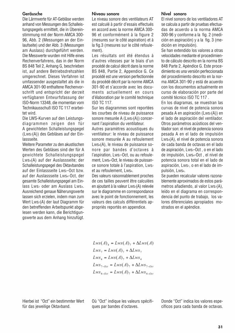
GeräuscheDie Lärmwerte für AT-Gebläse werdenanhand von Messungen des Schalleis-tungspegels ermittelt, die in Überein-stimmung mit der Norm AMCA 300-96, Abb. 2 (Messungen an der Ein-laufseite) und der Abb. 3 (Messungenam Auslass) durchgeführt werden.Die Messwerte wurden mit Hilfe einesRechenverfahrens, das in der NormBS 848 Teil 2, Anhang G, beschriebenist, auf andere Betriebsdrehzahlenumgerechnet. Dieses Verfahren istumfassender ausgestaltet als die inAMCA 301-90 enthaltene Rechenvor-schrift und entspricht der derzeitverfügbaren Entwurfsfassung derISO-Norm 13348, die momentan vomTechnikausschuß ISO TC 117 erarbei-tet wird.Die LWS-Kurven auf den Leistungs-diagrammen zeigen den fürA gewichteten Schalleistungspegel(Lws7(A)) des Gebläses auf der Ein-lassseite.Weitere Parameter zu den akustischenWerten des Gebläses sind der für Agewichtete SchalleistungspegelLws4(A) auf der Auslassseite; derSchalleistungspegel des Oktavbandesauf der Einlassseite Lws7-Oct bzw.auf der Auslassseite Lws4-Oct, dergesamte Schalleistungspegel am Ein-lass Lws7 oder am Auslass Lws4.Ausreichend genaue Näherungswertelassen sich erzielen, indem man zumWert Lws7(A) der laut Diagramm fürden betreffenden Arbeitspunkt abge-lesen werden kann, die Berichtigun-gswerte aus dem Anhang hinzufügt.
Hierbei ist “Oct” ein bestimmter Wertfür das jeweilige Oktavband.
Niveau sonoreLe niveau sonore des ventilateurs ATest calculé à partir d’essais effectuésen accord avec la norme AMCA 300-96 et conformément à la figure 2(mesures sur le côté aspiration) et àla fig.3 (mesures sur le côté refoule-ment).Les résultats ont été étendus àd’autres vitesses par le biais d’unprocédé de calcul décrit dans la normeBS 848, Partie 2, Appendice G. Ceprocédé est une version perfectionnéedu procédé décrit par la norme AMCA301-90 et s’accorde avec les docu-ments actuellement en coursd’élaboration par le comité techniqueISO TC 117.Sur les diagrammes sont reportéesles courbes de niveau de puissancesonore mesurée A (Lws7(A)) concer-nant l’aspiration du ventilateur.Autres paramètres acoustiques duventilateur: le niveau de puissancesonore mesurée A au refoulementLws4(A), le niveau de puissance so-nore par bandes d’octaves àl’aspiration, Lws7-Oct, ou au refoule-ment, Lws4-Oct, le niveau de puissan-ce sonore totale à l’aspiration, Lws7
et au refoulement, Lws4.Des valeurs raisonnablement prochesde ces tailles peuvent être calculéesen ajoutant à la valeur Lws7(A) relevéesur le diagramme en correspondanceavec le point de fonctionnement, lesvaleurs des calculs différentiels ap-propriés reportés en appendice.
Où “Oct” indique les valeurs spécifi-ques par bandes d’octaves.
Nivel sonoroEl nivel sonoro de los ventiladores ATse calcula a partir de pruebas efectua-das de acuerdo a la norma AMCA300-96 y conforme a la fig. 2 (medi-ción en aspiración) y a la fig. 3 (me-dición en impulsión).Se han extendido los valores a otrasvelocidades mediante el procedimien-to de cálculo descrito en la norma BS848 Parte 2, Apéndice G. Este proce-dimiento es una versión perfeccionadadel procedimiento descrito en la nor-ma AMCA 301-90 y está de acuerdocon los documentos actualmente encurso de elaboración por parte delcomité técnico ISO TC 117 .En los diagramas, se muestran lascurvas de nivel de potencia sonorapesada A en aspiración (Lws7(A)) enel lado de aspiración del ventilador.Otros parámetros acústicos del ven-tilador son: el nivel de potencia sonorapesada A en el lado de impulsiónLws4(A), el nivel de potencia sonorade cada banda de octavas en el ladode aspiración, Lws7-Oct , o en el ladode impulsión, Lws4-Oct , el nivel depotencia sonora total en el lado deaspiración, Lws7, o en el lado de im-pulsión, Lws4.Se pueden recalcular valores razona-blemente aproximados de estos pará-metros añadiendo, al valor Lws7(A),leído en el diagrama en correspon-dencia del punto de trabajo, los va-lores diferenciales apropiados mo-strados en el apéndice.
Donde “Oct” indica los valores espe-cíficos para cada banda de octavas.
31
OctOct
OctOct
LwsALwsLws
LwsALwsLws
LwsALwsLws
LwsALwsLws
ALwsALwsALws
−−
−−
∆+=
∆+=
∆+=
∆+=
∆+=
474
777
474
777
74
)(
)(
)(
)(
)()()(
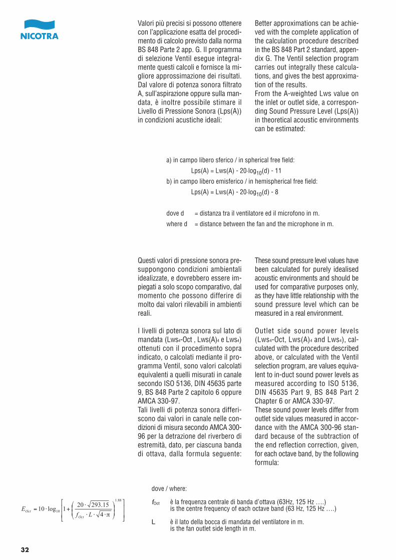
Valori più precisi si possono ottenerecon l’applicazione esatta del procedi-mento di calcolo previsto dalla normaBS 848 Parte 2 app. G. Il programmadi selezione Ventil esegue integral-mente questi calcoli e fornisce la mi-gliore approssimazione dei risultati.Dal valore di potenza sonora filtratoA, sull’aspirazione oppure sulla man-data, è inoltre possibile stimare ilLivello di Pressione Sonora (Lps(A))in condizioni acustiche ideali:
Questi valori di pressione sonora pre-suppongono condizioni ambientaliidealizzate, e dovrebbero essere im-piegati a solo scopo comparativo, dalmomento che possono differire dimolto dai valori rilevabili in ambientireali.
I livelli di potenza sonora sul lato dimandata (Lws4-Oct , Lws(A)4 e Lws4)ottenuti con il procedimento sopraindicato, o calcolati mediante il pro-gramma Ventil, sono valori calcolatiequivalenti a quelli misurati in canalesecondo ISO 5136, DIN 45635 parte9, BS 848 Parte 2 capitolo 6 oppureAMCA 330-97.Tali livelli di potenza sonora differi-scono dai valori in canale nelle con-dizioni di misura secondo AMCA 300-96 per la detrazione del riverbero diestremità, dato, per ciascuna bandadi ottava, dalla formula seguente:
Better approximations can be achie-ved with the complete application ofthe calculation procedure describedin the BS 848 Part 2 standard, appen-dix G. The Ventil selection programcarries out integrally these calcula-tions, and gives the best approxima-tion of the results.From the A-weighted Lws value onthe inlet or outlet side, a correspon-ding Sound Pressure Level (Lps(A))in theoretical acoustic environmentscan be estimated:
These sound pressure level values havebeen calculated for purely idealisedacoustic environments and should beused for comparative purposes only,as they have little relationship with thesound pressure level which can bemeasured in a real environment.
Outlet side sound power levels(Lws4-Oct, Lws(A)4 and Lws4), cal-culated with the procedure describedabove, or calculated with the Ventilselection program, are values equiva-lent to in-duct sound power levels asmeasured according to ISO 5136,DIN 45635 Part 9, BS 848 Part 2Chapter 6 or AMCA 330-97.These sound power levels differ fromoutlet side values measured in accor-dance with the AMCA 300-96 stan-dard because of the subtraction ofthe end reflection correction, given,for each octave band, by the followingformula:
a) in campo libero sferico / in spherical free field:
Lps(A) = Lws(A) - 20·log10(d) - 11
b) in campo libero emisferico / in hemispherical free field:
Lps(A) = Lws(A) - 20·log10(d) - 8
dove d = distanza tra il ventilatore ed il microfono in m.
where d = distance between the fan and the microphone in m.
fOct è la frequenza centrale di banda d’ottava (63Hz, 125 Hz ….)is the centre frequency of each octave band (63 Hz, 125 Hz ….)
L è il lato della bocca di mandata del ventilatore in m.is the fan outlet side length in m.
dove / where:
32
⎥⎥
⎦
⎤
⎢⎢
⎣
⎡
⎟⎟⎠
⎞⎜⎜⎝
⎛
⋅⋅⋅
⋅+⋅=
88.1
104
15.293201log10
πLfE
Oct
Oct
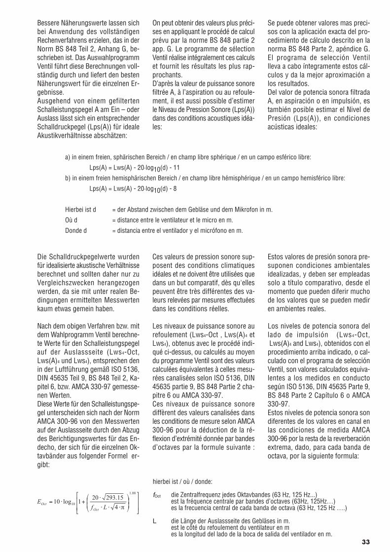
Bessere Näherungswerte lassen sichbei Anwendung des vollständigenRechenverfahrens erzielen, das in derNorm BS 848 Teil 2, Anhang G, be-schrieben ist. Das AuswahlprogrammVentil führt diese Berechnungen voll-ständig durch und liefert den bestenNäherungswert für die einzelnen Er-gebnisse.Ausgehend von einem gefiltertenSchalleistungspegel A am Ein – oderAuslass lässt sich ein entsprechenderSchalldruckpegel (Lps(A)) für idealeAkustikverhältnisse abschätzen:
Die Schalldruckpegelwerte wurdenfür idealisierte akustische Verhältnisseberechnet und sollten daher nur zuVergleichszwecken herangezogenwerden, da sie mit unter realen Be-dingungen ermittelten Messwertenkaum etwas gemein haben.
Nach dem obigen Verfahren bzw. mitdem Wahlprogramm Ventil berechne-te Werte für den Schalleistungspegelauf der Auslassseite (Lws4-Oct,Lws(A)4 und Lws4), entsprechen denin der Luftführung gemäß ISO 5136,DIN 45635 Teil 9, BS 848 Teil 2, Ka-pitel 6, bzw. AMCA 330-97 gemesse-nen Werten.Diese Werte für den Schalleistungspe-gel unterscheiden sich nach der NormAMCA 300-96 von den Messwertenauf der Auslassseite durch den Abzugdes Berichtigungswertes für das En-decho, der sich für die einzelnen Ok-tavbänder aus folgender Formel er-gibt:
On peut obtenir des valeurs plus préci-ses en appliquant le procédé de calculprévu par la norme BS 848 partie 2app. G. Le programme de sélectionVentil réalise intégralement ces calculset fournit les résultats les plus rap-prochants.D’après la valeur de puissance sonorefiltrée A, à l’aspiration ou au refoule-ment, il est aussi possible d’estimerle Niveau de Pression Sonore (Lps(A))dans des conditions acoustiques idéa-les:
Ces valeurs de pression sonore sup-posent des conditions climatiquesidéales et ne doivent être utilisées quedans un but comparatif, dès qu'ellespeuvent être très différentes des va-leurs relevées par mesures effectuéesdans les conditions réelles.
Les niveaux de puissance sonore aurefoulement (Lws4-Oct , Lws(A)4 etLws4), obtenus avec le procédé indi-qué ci-dessus, ou calculés au moyendu programme Ventil sont des valeurscalculées équivalentes à celles mesu-rées canalisées selon ISO 5136, DIN45635 partie 9, BS 848 Partie 2 cha-pitre 6 ou AMCA 330-97.Ces niveaux de puissance sonorediffèrent des valeurs canalisées dansles conditions de mesure selon AMCA300-96 pour la déduction de la ré-flexion d’extrémité donnée par bandesd’octaves par la formule suivante :
Se puede obtener valores mas preci-sos con la aplicación exacta del pro-cedimiento de cálculo descrito en lanorma BS 848 Parte 2, apéndice G.El programa de selección Ventillleva a cabo íntegramente estos cál-culos y da la mejor aproximación alos resultados.Del valor de potencia sonora filtradaA, en aspiración o en impulsión, estambién posible estimar el Nivel dePresión (Lps(A)), en condicionesacústicas ideales:
Estos valores de presión sonora pre-suponen condiciones ambientalesidealizadas, y deben ser empleadassolo a título comparativo, desde elmomento que pueden diferir muchode los valores que se pueden mediren ambientes reales.
Los niveles de potencia sonora dellado de impulsión (Lws4-Oct, Lws(A)4 and Lws4), obtenidos con elprocedimiento arriba indicado, o cal-culado con el programa de selecciónVentil, son valores calculados equiva-lentes a los medidos en conductosegún ISO 5136, DIN 45635 Parte 9,BS 848 Parte 2 Capítulo 6 o AMCA330-97.Estos niveles de potencia sonora sondiferentes de los valores en canal enlas condiciones de medida AMCA300-96 por la resta de la reverberaciónextrema, dado, para cada banda deoctava, por la siguiente formula:
a) in einem freien, sphärischen Bereich / en champ libre sphérique / en un campo esférico libre:
Lps(A) = Lws(A) - 20·log10(d) - 11
b) in einem freien hemisphärischen Bereich / en champ libre hémisphérique / en un campo hemisférico libre:
Lps(A) = Lws(A) - 20·log10(d) - 8
Hierbei ist d = der Abstand zwischen dem Gebläse und dem Mikrofon in m.
Où d = distance entre le ventilateur et le micro en m.
Donde d = distancia entre el ventilador y el micrófono en m.
hierbei ist / où / donde:
fOct die Zentralfrequenz jedes Oktavbandes (63 Hz, 125 Hz...)est la fréquence centrale par bandes d’octaves (63Hz, 125Hz…)es la frecuencia central de cada banda de octava (63 Hz, 125 Hz ….)
L die Länge der Auslassseite des Gebläses in m.est le côté du refoulement du ventilateur en mes la longitud del lado de la boca de salida del ventilador en m.
33
⎥⎥
⎦
⎤
⎢⎢
⎣
⎡
⎟⎟⎠
⎞⎜⎜⎝
⎛
⋅⋅⋅
⋅+⋅=
88.1
104
15.293201log10
πLfE
Oct
Oct
Nell’applicazione pratica, è importantericordare che la rumorosità del venti-latore installato può variare anche dimolto, rispetto ai livelli registrati incondizioni di laboratorio.Vibrazioni meccaniche alle frequenzedi rotazione del ventilatore e del mo-tore, oppure alle frequenze di vibra-zione interna di quest’ultimo, possonofacilmente irradiare rumore estraneoal ventilatore, generalmente con picchiben definiti in frequenza. La rispostameccanica del ventilatore alle vibra-zioni indotte è, inoltre, fortementeinfluenzata dalla rigidezza dei supportie del telaio di basamento che lo col-lega al motore.Trafilamenti d’aria nei raccordi, o tur-bolenze generate da griglie di prote-zione o di diffusione, da protezionidella trasmissione o da raccordi neicanali possono alterare apprezzabil-mente anche il rumore aerodinamicoa larga banda, e specialmente ad altafrequenza.Per finire, l’ampiezza della pulsazionealla frequenza di passaggio pala puòcambiare notevolmente, anche di mol-ti decibel, per effetto delle condizionidi risonanza che possono verificarsinel canale o nella camera a valle diun ventilatore.Nel la maggioranza dei casi ,l’incremento di rumorosità a largabanda, derivante dalle condizioni diinstallazione reale, è contenuto incirca 2 dB. Più difficile è prevederel’incremento di rumorosità che puòprodursi per effetto delle vibrazionimeccaniche, che dipende dalle carat-teristiche degli altri elementi meccaniciimpiegati (basamento, motore, puleg-ge), e l’esatta rumorosità alla frequen-za di passaggio pala, che può aumen-tare o diminuire per effetto dallecaratteristiche acustiche dei canaliconnessi al ventilatore.
The user should remember that thesound power level of a fan, as installedin practice, could be significantly hi-gher than that measured in laboratoryconditions.Mechanical vibrations at the rotationfrequencies of the fan and of the dri-ving motor, and at the internal vibra-tion frequencies of the same motor,can easily radiate noise which is notactually produced by the fan, usuallyshowing narrow peaks at well-definedfrequencies. The mechanical reactionof the fan structure to induced vibra-tions is highly influenced by the stif-fness of the base frame, holding to-gether fan and motor.Air leakage through the connections,or turbulence produced by guards,diffuser grids or transition pieces canalso significantly change the broad-band noise spectrum, particularly athigh frequency.As a final note, the actual amplitudeof the blade passing frequency peakcan be changed by many decibels asan effect of the acoustic resonanceproperties of the duct or plenum con-nected to the fan.In most cases, the broadband noiselevel increase, produced by a reaso-nable real-life installation, is keptwithin 2 dBW. Much more difficultmay be the prediction of the noiseincrease produced by mechanicalvibrations, as this depends on themechanical characteristics of manyother components (base frame, mo-tor, pulleys and so on), and of theblade passing frequency tone, whichdepends on the acoustic propertiesof the duct system.
34
Der Anwender sollte sich dabei vorAugen halten, dass der Schalleistun-gspegel eines real eingebauten Geblä-ses in der Praxis erheblich höherliegen kann als bei Messungen unterLaborbedingungen.Mechanische Schwingungen bei denDrehzahlen des Gebläses sowie desAntriebsmotors und die Vibrationsfre-quenzen im Innern des gleichen Mo-tors können ohne weiteres Lärm ab-strahlen, der nicht unmittelbar aufdas Gebläse zurückzuführen ist undüblicherweise eng eingegrenzte Spit-zenwerte bei genau definierten Fre-quenzen aufweist. Die durch induzierteVibrationen ausgelösten mechani-schen Wirkungen für die Gebläse-struktur werden in hohen Maße durchdie Steifigkeit der Rahmenstrukturbeeinflusst, in die Gebläse und Motoreingebaut sind.Luftverluste durch Anschlüsse bzw.Verwirbelungen, die auf Schutzvorri-chtungen, Diffusorgitter oder Über-gangsteile zurückzuführen sind, kön-nen das Breitbandspektrum für denLärm insbesondere bei hohen Fre-quenzen signifikant abändern.Abschließend ist zu sagen, dass dietatsächliche Amplitude der Frequenz-spitzen für die Lüfterblätter sich auf-grund der Resonanzeigenschaftendes Un te rg runds bzw. de rLüftungskanäle ändern kann, an de-nen das Gebläse befestigt ist.In den meisten Fällen lässt sich diebreitbandige Geräuschpegelzunahme,die von einer tatsächlich installiertenAnlage ausgeht, auf höchstens 2 dBbeschränken. Sehr viel schwierigerist unter Umständen die Vorhersageder Lärmzunahme, die auf mechani-sche Schwingungen zurückzuführenist, da dieser Wert von den mechani-schen Kennwerten zahlreicher weite-rer Baugruppen (Grundrahmen, Mo-tor, Riemenscheiben usw.) sowie vonder Frequenz beim Lüfterraddurchsatzabhängig ist, die von den akustischenEigenschaften der Lüftungskanälebestimmt wird.
Dans l’application pratique, il est im-portant de noter que le niveau sonoredu ventilateur installé peut varier énor-mément par rapport aux niveaux en-registrés dans les conditions de labo-ratoire.Des vibrations mécaniques dues auxfréquences de rotation du ventilateuret du moteur ou aux fréquences devibration interne de ce dernier, peu-vent facilement diffuser des bruitsétrangers au ventilateur et générale-ment avec des pics bien définis enfréquence. La réponse mécanique duventilateur aux vibrations induites estfortement influencée par la rigiditédes supports et du cadre de base quile relie au moteur.Des fuites d’air dans les raccordemen-ts ou des turbulences générées parles grilles de protection ou de diffusionou par les raccordements des canali-sations peuvent altérer considérable-ment le bruit aérodynamique à largesbandes et spécialement à hautefréquence.Pour finir, l’importance de la pulsationde la fréquence du passage de l’aubepeut également varier considérable-ment de plusieurs décibels à causedes conditions de résonnance produi-tent dans les gaines ou dans la pièceen aval d’un ventilateur.Dans l a p l upa r t des cas ,l’augmentation du niveau sonore parlarge bande d’octave découlant desconditions d’installation réelle estcontenue dans environ 2 dB. Il estplus difficile de prévoir l’augmentationdu niveau sonore pouvant se produirepar effet des vibrations mécaniques,qui dépend des caractéristiques desautres éléments mécaniques utilisés(support, moteur, poulies) et le niveausonore exact à la fréquence de pas-sage des aubes pouvant augmenterou diminuer à cause des caractéristi-ques acoustiques des gaines reliéesau ventilateur.
En la aplicación práctica, es impor-tante recordar que el nivel sonoro delventilador instalado puede variar tam-bién mucho respecto a los nivelesregistrados en condiciones de labo-ratorio.Las vibraciones mecánicas a la fre-cuencia de rotación del ventilador ydel motor y a la frecuencia de vibra-ción interna de este ultimo, puedenfácilmente irradiar ruidos extraños alventilador, generalmente con picosbien definidos en frecuencia. La re-spuesta mecánica del ventilador a lasvibraciones inducidas está tambiénfuertemente influenciada por la rigidezde los soportes y de la bancada quelo une al motor.Pérdidas de aire en la embocadura,o turbulencias generadas por rejillasde protección o de difusión, de pro-tecciones de la transmisión o de em-palmes en el conducto pueden alterarapreciablemente también el ruido ae-rodinámico en banda alta y especial-mente a alta frecuencia.Para terminar, la amplitud de la pul-sación a la frecuencia de paso de palapuede cambiar notablemente, inclusode muchos decibelios, por efecto delas condiciones de resonancia quepueden verificarse en el conducto oen la cámara que sigue al ventilador.En la mayoría de los casos, el incre-mento del nivel sonoro en banda altaderivadas de las condiciones de in-stalación real está comprendido encerca de 2 dB. Mas difícil es preverel incremento de nivel sonoro quepuede producirse por efecto de lasvibraciones mecánicas, que dependende las características de los otroselementos mecánicos empleados(bancadas, motor, poleas), y el nivelsonoro exacto a la frecuencia de pasode pala, que puede aumentar o dismi-nuir por efecto de las característicasacústicas de los conductos conecta-dos al ventilador.
35
Zona di normale impiegoIl diagramma di funzionamento deiventilatori AT è diviso in tre zone dadue righe rosse parallele alle linee diefficienza costante. Le due righe rossedelimitano la zona di normale impiegodel ventilatore (al centro) dalla zonadi stallo (in alto a sinistra) e dallazona di bassa pressione (in basso adestra). Un dimensionamento correttodel ventilatore porta ad avere il puntodi funzionamento entro la zona dinormale impiego e, preferibilmente,sulla linea di massima efficienza olievemente più a destra.La scelta di una grandezza di ventila-tore che comporta un punto di fun-zionamento nella zona di bassa pres-sione è sconsigliata: in questecondizioni, infatti, non solo si ottieneun’efficienza scarsa, ma il ventilatorepuò produrre forti e fastidiose oscil-lazioni della pressione erogata. Percorreggere un dimensionamento diquesto tipo, occorre scegliere un ven-tilatore di grandezza maggiore oppureun ventilatore binato.La scelta di un ventilatore con il puntodi funzionamento nella zona di stalloè preferibilmente da evitarsi: anchein queste condizioni il ventilatore èscarsamente efficiente e produce unapressione fluttuante ed una forte com-ponente di rumore a bassa pressione,che incide scarsamente sul valore dellivello di potenza sonora totale filtratoA, ma che può rivelarsi assai fastidio-so. Il problema può essere agevol-mente prevenuto scegliendo un ven-tilatore di grandezza più piccola opassando ad un ventilatore a palarovescia.Le curve di funzionamento dei venti-latori sono estese fuori della zona dinormale impiego con lo scopo di age-volare la diagnosi degli impianti, infase di messa in opera, ma le presta-zioni dei ventilatori in queste condi-zioni sono soggette a notevoli incer-tezze, dovute anche all’influenza delsistema connesso al ventilatore.
Normal operating areaThe performance diagram of AT fansis divided into three areas by two redlines, parallel to the constant efficiencylines. The two red lines separate thenormal operating area of the fan (inthe middle), from the stall region (top-left area) and from the low-pressureregion (bottom-right area).An appropriate selection of the fansize gives an operating point withinthe normal operation area of the fan,and, ideally, on or slightly right of thebest efficiency line of the fan.A fan size selection producing anoperating point in the low pressurearea of the diagram should preferablybe avoided: in fact any fan operatingunder these conditions is not onlyhighly inefficient, but may be alsobeat annoyingly, because of the strongpressure fluctuations. To rectify sucha selection, a larger fan size or a twinfan should be used.A fan size selection with the operatingpoint in the stall region should becarefully avoided; any fan operatingunder these conditions is again scar-cely efficient and generates a fluctua-ting pressure and a high noise levelin the lower frequency octaves, whichwill give little contribution to the A-weighted total noise level, but maybe highly intrusive. Such a fan choicecan be easily rectified, selecting asmaller and faster turning fan size;alternatively, a backward inclined fanshould be substituted to a similarlysized AT forward curved one.The performance curves of the ATfans have been extended outside thenormal operation range to assist withtroubleshooting at system start-uptime, but fan performance in theseconditions is subject to increaseduncertainty, depending also on theinfluence of the air system connectedto the fan.
36
Normaler BetriebsbereichDas Leistungsdiagramm von AT-Gebläsen wird durch zwei rote Linien,die parallel zu den Linien für die Wirk-samkeitskonstante verlaufen, in dreiBereiche untergliedert. Die beidenroten Linien trennen den normalenBetriebsbereich eines Gebläses (inder Mitte) vom Abreißbereich (obenlinks) und dem Unterdruckbereich(unten rechts).Eine geeignete Größenauswahl fürdas Gebläse entspricht einem Arbei-tspunkt, der innerhalb des Bereichsfür den Normalbetrieb liegt und idea-lerweise auf oder etwas rechts vonder Linie für die beste Wirksamkeitdes Gebläses liegen soll. Eine Geblä-seauswahl, die zu einem Arbeitspunktim Unterdruckbereich des Diagrammsführt, sollte vorzugsweise vermiedenwerden: unter derartigen Bedingungenist der Ventilator nicht nur wenig ef-fizient, sondern erzeugt auchschwankenden Druck, der jedochstark und sehr lästig sein kann. Umeinen derartigen Fehler zu beheben,sollte ein größeres Gebläse oder einZwillingsgebläse eingesetzt werden.Besonders ist darauf zu achten, dassdie Gebläsewahl nicht zu einem Ar-beitspunkt im Abreißbereich führt:auch unter derartigen Bedingungenist der Ventilator nicht nur wenig ef-fizient, sondern erzeugt auchschwankenden Druck und einenhohen Geräuschpegel in den unterenOktaven; dies trägt zwar kaum zumgesamten Geräuschpegel einer für Agerichteten Anlage bei, kann jedochsehr lästig sein.Der Fehler lässt sich problemlos durchEinsatz eines kleineren Gebläses behe-ben; alternativ können Ventilatorenmit rückwärtsgekrümmten Schaufelneingesetzt werden. Die Leistungskur-ven für AT-Gebläse wurden über dennormalen Betriebsbereich hinaus ver-längert, um bei der Fehlersuchewährend des Anlaufs der Anlagebehilflich zu sein; Gebläseleistungenunter diesen Bedingungen sind jedochauch deshalb sehr unsicher, weil diemit dem Gebläse verbundeneLüftungsanlage hier ebenfalls dieParameter beeinflusst.
Zone d’utilisation normaleLa courbe de fonctionnement desventilateurs AT est divisée en troiszones par deux lignes rouges parallè-les à la ligne de rendement constant.Les deux lignes rouges délimitent lazone normale d’utilisation du ventila-teur (au centre) de la zone de pertede vitesse (en haut à gauche) et dela zone de basse pression (en bas àdroite). Un dimensionnement correctdu ventilateur amène à avoir un pointde fonctionnement entre la zoned’utilisation normale et de préférencesur la ligne de rendement maximumou légèrement plus à droite.Le choix d’une taille de ventilateurcomportant un point de fonctionne-ment dans la zone de basse pressionest déconseillé à cause du faible ren-dement, ainsi que de la grande incer-titude des performances. Pour corri-ger un dimensionnement de ce type,il faut choisir un ventilateur de taillesupérieure ou un ventilateur double.Le choix d’un ventilateur ayant unpoint de fonctionnement dans la zonede perte de vitesse est de préférenceà éviter: aussi tout ventilateur fonc-tionnant dans ces conditions est nonseulement peu efficace mais produitaussi une pression fluctuante et uneforte composante de bruit à bassepression qui influe faiblement sur lavaleur du niveau de puissance sonoretotale filtrée A. Choisir dans ce casun ventilateur de plus petite taille oupasser à un ventilateur à aubes in-clinées vers l'arrière.Les courbes de fonctionnement desventilateurs sont étendues hors de lazone d’utilisation normale dans le butde faciliter le diagnostic des installa-tions en phase de montage, mais lesperformances des ventilateurs dansces conditions sont sujettes àd’importantes incertitudes, dûes aussià l’influence du système relié au ven-tilateur.
Zona normal de empleoEl diagrama de funcionamiento de losventiladores AT está dividido en treszonas por dos líneas rojas paralelasa las líneas de rendimiento constante.Las dos líneas rojas delimitan la zonade empleo normal del ventilador (enel centro) de la zona crítica (en altoa la izquierda) y de la zona de bajapresión (abajo a la derecha). Un di-mensionamiento correcto del ventila-dor lleva a tener el punto de trabajodentro de la zona de funcionamientonormal, y preferiblemente sobre lalínea de máximo rendimiento o lige-ramente a la derecha.Se debe evitar la selección de tamañode ventilador que comporta un puntode funcionamiento en el área de bajapresión: de hecho un funcionamientodel ventilador en estas condicionesno solo da poco rendimiento sinopuede también ser molesto por losfuertes fluctuaciones de presión. Pararectificar tal selección se debe usarun tamaño mas grande o un ventila-dor doble.Se debe poner cuidado en evitar laselección de un ventilador con el pun-to de trabajo en la zona crítica: tam-bién en estas condiciones el ventiladores escasamente eficiente y produceuna presión fluctuante y una fuertecomponente de ruido a baja presiónque incide escasamente sobre el valordel nivel de potencia sonora totalfiltrado A, pero que puede convertirseen muy fastidioso. El problema puedeser fácilmente prevenido seleccionan-do un ventilador de un tamaño inferioro pasando a un ventilador de palashacia atrás.Las curvas de funcionamiento de losventiladores se extienden fuera de lazona de funcionamiento normal conel fin de facilitar el diagnóstico de lasinstalaciones en fase de puesta enmarcha, pero las prestaciones de losventiladores en estas condicionesestán sujetas a notables incertidum-bres debidas también a la influenciadel sistema conectado al ventilador.
37
TolleranzeI ventilatori AT di tutte le taglie, hannoprestazioni aerauliche, e rumorositàin condizioni di prova secondo AMCA300-96, tali da rientrare nelle tolleran-ze indicate nella norma DIN 24166,Classe 2.
Certificazione delle prestazioniNicotra S.p.A. certifica che i ventilatoriserie AT, nelle versioni singole S, SC,C, AR, e TIC, sono autorizzati a portareil Marchio AMCA. Le prestazioni indi-cate a catalogo sono basate su provee procedure in accordo con il docu-mento AMCA 211, e soddisfano i re-quisiti del Programma AMCA per laCertificazione delle Prestazioni. IlMarchio di Certificazione AMCA siapplica alle sole prestazioni aerauliche.
Le prestazioni aerauliche nel funzio-namento in installazione “A” (a BoccaLibera) e quelle delle versioni binateG2L, SC2, G2C e G2C-C2, nonchédelle versioni trinate G3C e G3C-C2non sono certificate AMCA.
Prestazioni dei ventilatori binati G2Le prestazioni di un ventilatore binato,ovvero di una versione identificatadal prefisso "G2", si calcolano, a partiredal corrispondente punto di lavoro diun ventilatore singolo, applicando leformule sotto elencate.
Le prestazioni così calcolate non sonocertificate AMCA.
I limiti massimi di velocità e potenzaammessi per i ventilatori binati sonodiversi da quelli relativi ai ventilatorisingoli di analoga costruzione. Per ilimiti delle versioni binate, si consultila tabella “Limiti di impiego” a pag. 55.
TolerancesAll sizes of AT fans have air perfor-mance and sound power levels, asmeasured according to the AMCA300-96 standard, within the tolerancesallowed by the DIN 24166 standardfor Class 2.
Certified RatingsNicotra S.p.A. certifies that AT fansof the S, SC, C, AR, and TIC versions,shown herein, are licensed to bearthe AMCA Seal. The ratings shownare based on tests and proceduresperformed in accordance with AMCApublication 211 and comply with therequirements of the AMCA CertifiedRatings Program. The AMCA CertifiedRatings Seal applies to air performan-ce ratings only.
Air performance with Installation type“A” (with free outlet) and that of twinand triple versions, in any installationtype, is not AMCA Licensed.
Performance of twin fan units G2The performance of twin fan units,identified by the “G2” code, can becalculated, starting from that in thecorresponding operating point for asingle fan, with the following formu-las.
Fan performance so calculated is notAMCA Licensed.
Speed and power limits for AT twinfan units may be different from thoseof similarly built single-impeller ver-sions. The appropriate performancelimits for AT twin fan versions can befound in the table “OperationalLimits”, on page 55.
- pressione / pressure : Pb = P x 1- portata / volume flow rate : Qb = Q x 2- potenza assorbita / impeller power: Wb = W x 2,15- numero di giri / fan speed : Nb = N x 1,05- rumorosità / Lws : Lwsb = Lws + 3 dB
38
ToleranzenAlle Größen der AT-Gebläse verfügenüber Durchsatzleistungen und Schall-leistungspegel, die laut Messunggemäß der Norm AMCA300-96 inner-halb der Toleranzen liegen, die lautDIN 24166 für Anlagen der Klasse 2zulässig sind.
Bescheinigte LeistungsdatenNicotra S.p.A. bescheinigt, dass diehier dargestellten AT-Lüfter des TypsS, SC, C, AR, und TIC von der AMCAzur Führung ihres Siegels zugelassensind. Die dargestellten Einstufungenberuhen auf Prüfungen und Verfahren,die gemäß AMCA Druckschrift 211durchgeführt wurden und den Erfor-dernissen eines von der AMCA zuge-lassenen Einstufungsprogramms ent-sprechen. Das entsprechende AMCASiegel gilt nur für die Luftdurchsatz-leistungen.
Der Luftdurchsatz bei Anlagen desTyps “A” (ohne Luftführungselementam Auslass) und die von den Zwillin-gsversionen G2L, SC2, G2C, G2-C2,sowie Drillingsversionen G3C undG3C-C2 verfügen nicht über eineAMCA-Zulassung.
Leistungsdaten für Zwillingsgeblä-seeinheiten G2Die Leistungsdaten für Zwillingsge-bläse, die durch das Präfix "G2“gekennzeichnet sind, lassen sich aus-gehend von den entsprechenden Wer-ten für den Arbeitspunkt eines Einzel-gebläses anhand folgender Formelnberechnen.
Für die Messung von Gebläseleistun-gen nach diesem Verfahren liegt keineAMCA-Lizenz vor.
Die maximal zulässigen Drehzahl undDurchfluß bei Zwillingsventilatoren ent-sprechen nicht denen von Einzelventila-toren bei analoger Bauweise. Zur Erre-chnung des Limits für Zwillingsgebläseziehen Sie bitte die Tabelle "Anwendun-gsgrenzen" auf Seite 55 zu Rate.
TolérancesToutes les tailles des ventilateurs ATont, en conditions d’essais selonAMCA 300-96, des performancesaérauliques et des niveaux sonoresqui peuvent rentrer dans les toléran-ces indiquées dans la norme DIN24166, Classe 2.
Certification des performancesNicotra S.p.A. certifie que les versionssimples S, SC, C, AR et TIC des ven-tilateurs de la série AT sont autorisésà porter la Marque AMCA. Les perfor-mances indiquées au catalogue sontbasées sur des essais et procéduresen accord avec le document AMCA211 et répondent aux demandes duProgramme AMCA pour la Certifica-tion des Performances. La Marquede certification AMCA s’applique auxseules performances aérauliques.
Les performances aérauliques en fon-ctionnement installation “A” (BoucheBée), celles des versions doublesG2L, SC2, G2C et G2C-C2 et cellesdes versions triples G3C et G3C-C3ne sont pas certifiées AMCA.
Performances des ventilateurs dou-bles G2Les performances d’un ventilateurdouble, identifié par “G2” se calculentà partir du point de fonctionnementcorrespondant à un ventilateur simpleen appliquant les formules ci-dessous.
Les performances ainsi calculées nesont pas certifiées AMCA.
Les limites maximum de vitesse et depuissance admis pour les ventilateursdoubles sont différentes par rapport àcelles des ventilateurs simples de con-struction analogue. Pour les limites desversions doubles, se reporter au tableau"Limites d'utilisation", à la page 55.
ToleranciasTodos los tamaños de ventiladoresAT tienen prestaciones aerólicas y denivel sonoro en condiciones de pruebasegún AMCA 300-96, dentro de lastolerancias permitidas por la normaDIN 24166, Clase 2.
Certificación de las PrestacionesNicotra S.p.A. certifica que los venti-ladores de la serie AT, en las versionessimples S, SC, C, AR, y TIC estánautorizados para llevar el sello AMCA.Las prestaciones indicadas se basanen pruebas y procedimientos deacuerdo con el documento AMCA 211y cumplen con los requisitos del Pro-grama AMCA para la Certificación delas Prestaciones. El sello de certifica-ción AMCA se aplica solo a las pre-staciones aerólicas.
Las prestaciones aerólicas con fun-cionamiento en instalación tipo “A”(a boca libre) y de los versiones do-bles G2L, SC2, G2C y G2C-C2 y triplesG3C y G3C-C2 no están certificadasAMCA.
Funcionamiento de ventiladoresdobles G2Las prestaciones de un ventiladordoble, o sea las versiones identifica-das por el prefijo “G2”, se calculan apartir del correspondiente punto detrabajo de un ventilador simple, apli-cando las fórmulas abajo indicadas.
Las prestaciones así calculadas noestán certificadas AMCA.
Los limites máximos de velocidad y poten-cia admitidos por los ventiladores doblesson diferentes de los limites de similaresversiones simples. Se pueden encontrarlos limites apropiados de funcionamientode ventiladores dobles en la tabla “Límitesde empleo”, en la página 55.
- Druck / pression / presión : Pb = P x 1- Volumendurchfluss / débit / caudal : Qb = Q x 2- Lüfterradleistung / puissance absorbée / potencia absorbida: Wb = W x 2,15- Gebläsedrehzahl / nombre de tours / velocidad ventilador : Nb = N x 1,05- Geräuschpegel / niveau sonore / nivel sonoro : Lwsb = Lws + 3 dB
39
Prestazioni dei ventilatori trinati G3Le prestazioni di un ventilatore trinato,ovvero di una versione identificatadal prefisso "G3", si calcolano, a partiredal corrispondente punto di lavoro diun ventilatore singolo, applicando leformule sotto elencate.
Le prestazioni così calcolate non sonocertificate AMCA.
I limiti massimi di velocità e potenzaammessi per i ventilatori trinati sonodiversi da quelli relativi ai ventilatorisingoli di analoga costruzione. Per ilimiti delle versioni trinate, si consultila tabella “Limiti di impiego” a pag. 55.
Performance of triple fan units G3The performance of triple fan units,identified by the “G3” code, can becalculated, starting from that in thecorresponding operating point for asingle fan, with the following formu-las.
Fan performance so calculated is notAMCA Licensed.
Speed and power limits for AT triplefan units may be different from thoseof similarly built single-impeller ver-sions. The appropriate performancelimits for AT triple fan versions canbe found in the table “OperationalLimits”, on page 55.
- pressione / pressure : Pb = P x 1- portata / volume flow rate : Qb = Q x 3- potenza assorbita / impeller power: Wb = W x 3,25- numero di giri / fan speed : Nb = N x 1,08- rumorosità / Lws : Lwsb = Lws + 5 dB
40
Leistungsdaten für Drillingsgeblä-seeinheiten G3Die Leistungsdaten für Drillingsgeblä-se, die durch das Präfix "G3" gekenn-zeichnet sind, lassen sich ausgehendvon den entsprechenden Werten fürden Arbeitspunkt eines Einzelgeblä-ses anhand folgender Formel berech-nen.
Für die Messung von Gebläseleistun-gen nach diesem Verfahren liegt keineAMCA-Lizenz vor.
Die maximal zulässigen Drehzahl undDurchfluß bei Drillingsventilatorenentsprechen nicht denen von Einzel-ventilatoren bei analoger Bauweise.Zur Errechnung des Limits für Drillin-gsgebläse ziehen Sie bitte die Tabelle"Anwendungsgrenzen" auf Seite 55zu Rate.
Performances des ventilateurs tri-ples G3Les performances d’un ventilateurtriple, identifié par “G3” se calculentà partir du point de fonctionnementcorrespondant à un ventilateur simpleen appliquant les formules ci-dessous.
Les performances ainsi calculées nesont pas certifiées AMCA.
Les limites maximum de vitesse etde puissance admis pour les ventila-teurs triples sont différentes par rap-port à celles des ventilateurs simplesde construction analogue. Pour leslimites des versions triples, se repor-ter au tableau "Limites d'utilisation",à la page 55.
Funcionamiento de ventiladorestriples G3Las prestaciones de un ventiladortriple, o sea las versiones identificadaspor el prefijo “G3”, se calculan a partirdel correspondiente punto de trabajode un ventilador simple, aplicandolas fórmulas abajo indicadas.
Las prestaciones así calculadas noestán certificadas AMCA.
Los límites máximos de velocidad ypotencia admitidos por los ventilado-res triples son diferentes de los limitesde similares versiones simples. Sepueden encontrar los límites apropi-ados de funcionamiento de ventilado-res triples en la tabla “Límites deempleo”, en la página 55.
- Druck / pression / presión : Pb = P x 1- Volumendurchfluss / débit / caudal : Qb = Q x 3- Lüfterradleistung / puissance absorbée / potencia absorbida: Wb = W x 3,25- Gebläsedrehzahl / nombre de tours / velocidad ventilador : Nb = N x 1,08- Geräuschpegel / niveau sonore / nivel sonoro : Lwsb = Lws + 5 dB
41
QUICK SIZE-SELECTION PROCE-DURE
When the selection of the appropriatefan size is carried out using the volu-me flow rate combined with the Totalpressure value (which is the mostappropriate approach for fans usedin a “B” installation type), the fastestway to select the correct fan size isto calculate the dimensional parabolicconstant of the required operatingpoint, KP, defined as
As a following step, the “KEtaOpt” colu-mn should be searched, looking forthe smallest value equal or larger thanthe calculated one. The fan size shownon the same level in the leftmost co-lumn is the first choice for a singlefan.To select a twin fan, only half of thetotal flow rate shall be used to calcu-late the parabolic constant Kp.For a correct selection of a triple fanunit, one third of the total, requiredvolume flow must be used to calculatethe parabolic constant, Kp.
PROCEDIMENTO DI SCELTA RAPIDA
Disponendo dei valori di portata epressione totale (inclusa la pressionedinamica) richieste al ventilatore, ilmodo più rapido per selezionare ilventilatore della grandezza più appro-priata consiste nel calcolare la costan-te parabolica dimensionale KP delpunto di lavoro richiesto, definitacome
Con il valore trovato, si consulta latabella sottostante, cercando nellacolonna “KEtaOpt” il più piccolo valoremaggiore o uguale al valore di Kp
calcolato.Il ventilatore singolo ottimale è quellocon la grandezza indicata nella colon-na di sinistra.Per individuare la grandezza ottimaledi un ventilatore binato è sufficienteeffettuare le stesse operazioni, consi-derando solo metà della portata totalerichiesta al gruppo binato.La scelta di un gruppo trinato si effet-tua, invece, usando solo un terzo dellaportata totale per calcolare la costanteparabolica Kp.
dove / where:
PFB è la Pressione Totale espressa in Pais the Fan Total Pressure in Pa
Q è la Portata espressa in m3/s, del punto di lavoro richiestois the Volume Flow rate in m3/s, of the required operating pointè la densità dell’aria (1.2 kg/m3 in condizioni normali)is the Air Density (1.2 kg/m3 in standard conditions)
42
ρ2.1
2⋅=
Q
PK FBP
ρ
KURZVERFAHREN ZUR GRÖSSEN-AUSWAHL
Unter Voraussetzung der Kenntnisvon Volumendurchfluss und Ge-samtdruck (inklusiv dynamischerDruck) ist der schnellste Weg zurE r m i t t l u n g d e r g e e i g n e t e nGebläsegröße, die Errechnung derparabolische Maßkonstante für denbenötigten Arbeitspunkt KP, für dendie Definition wie folgt lautet
Nach Erhalt des gesuchten Wertes istals nächstes die Spalte "KEtaOpt“ nachdem kleinsten Wert abzusuchen, derdem berechneten Wert entspricht oderetwas über ihm liegt.Die Gebläsegröße in der am weitestenlinks befindlichen Spalte eben dieserZeile kommt als erster für ein Einzel-gebläse in Frage. Bei der Auswahleines Zwillingsgebläses wird nun dieHälfte des Gesamtwertes für den Dur-chstrom verwendet. Zur Berechnungder parabolischen Konstante Kp beiDrillingsgebläse verwendet man einDrittel des Gesamtvolumens.
PROCÉDÉ DE CHOIX RAPIDE
La façon la plus rapide de sélectionnerla taille la plus appropriée d’un venti-lateur, quand on connait le débit et lapression totale (incluse la pressiondynamique), consiste en calculer laconstante parabolique dimensionnelleKP du point de fonctionnement de-mandé, défini ainsi
Avec la valeur trouvée, on consultele tableau ci-dessous en cherchantdans la colonne “KEtaOpt” la plus petitevaleur supérieure ou égale à la valeurde Kp calculée.Le ventilateur simple optimal est celuidont la taille est indiquée dans lacolonne de gauche.Pour repérer la taille optimale d’unventilateur double, il suffit d’effectuerles mêmes opérations en considérantseulement la moitié du débit totalrequis au groupe double.Le choix d'un ventilateur triple, aucontraire, est effectué en utilisantseulement un tiers du débit total pourcalculer la constante parabolique Kp.
PROCEDIMIENTO DE SELECCIÓNRÁPIDA
Disponiendo de los valores de caudaly presión total (incluida la presióndinámica) pedidas al ventilador, elmodo mas rápido para seleccionar elventilador del tamaño apropiado con-siste en calcular la constante parabóli-ca dimensional KP para el punto detrabajo requerido, definida como
Con el valor encontrado se consultala tabla de abajo buscando en la co-lumna “KEtaOpt” el valor mas pequeñomayor o igual al valor Kp calculado.El ventilador simple óptimo es aquelcon el tamaño indicado en la columnade la izquierda.Para seleccionar el tamaño optimode un ventilador doble es suficientecon efectuar las mismas operaciones,considerando solo la mitad del caudalrequerido al grupo doble.La selección correcta de un ventiladortriple, se efectúa usando solo un terciodel caudal total para calcular la con-stante parabólica, Kp.
43
ρ2.1
2⋅=
Q
PK FBP
Hierbei / Où / donde:
PFB ist der Gesamtdruck in Paest la Pression Totale exprimée en Paes la presión total del ventilador en Pa
Q ist der Volumendurchfluss in m3/s des geforderten Arbeitspunktesest le débit exprimé en m3/s, du point de fonctionnement demandées el caudal expresado en m3/s, del punto de trabajo requeridoist die Luftdichte (1.2 kg/m3 bei normalen Bedingungen)est la densité de l’air (1.2 kg/m3 en conditions normales)es la densidad de aire (1.2 kg/m3 en condiciones estándar)
ρ
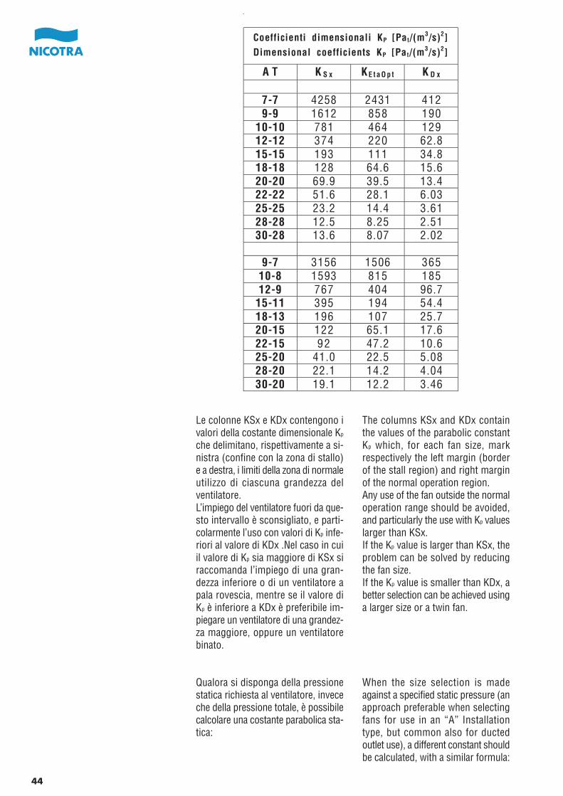
The columns KSx and KDx containthe values of the parabolic constantKp which, for each fan size, markrespectively the left margin (borderof the stall region) and right marginof the normal operation region.Any use of the fan outside the normaloperation range should be avoided,and particularly the use with Kp valueslarger than KSx.If the Kp value is larger than KSx, theproblem can be solved by reducingthe fan size.If the Kp value is smaller than KDx, abetter selection can be achieved usinga larger size or a twin fan.
When the size selection is madeagainst a specified static pressure (anapproach preferable when selectingfans for use in an “A” Installationtype, but common also for ductedoutlet use), a different constant shouldbe calculated, with a similar formula:
Le colonne KSx e KDx contengono ivalori della costante dimensionale Kp
che delimitano, rispettivamente a si-nistra (confine con la zona di stallo)e a destra, i limiti della zona di normaleutilizzo di ciascuna grandezza delventilatore.L’impiego del ventilatore fuori da que-sto intervallo è sconsigliato, e parti-colarmente l’uso con valori di Kp infe-riori al valore di KDx .Nel caso in cuiil valore di Kp sia maggiore di KSx siraccomanda l’impiego di una gran-dezza inferiore o di un ventilatore apala rovescia, mentre se il valore diKp è inferiore a KDx è preferibile im-piegare un ventilatore di una grandez-za maggiore, oppure un ventilatorebinato.
Qualora si disponga della pressionestatica richiesta al ventilatore, inveceche della pressione totale, è possibilecalcolare una costante parabolica sta-tica:
Coefficienti dimensionali KP [Pat/(m3/s)2]
Dimensional coefficients KP [Pat/(m3/s)2]
A T K S x KE t a O p t K D x
7-7 4258 2431 4129-9 1612 858 190
10-10 781 464 12912-12 374 220 62.815-15 193 111 34.818-18 128 64.6 15.620-20 69.9 39.5 13.422-22 51.6 28.1 6.0325-25 23.2 14.4 3.6128-28 12.5 8.25 2.5130-28 13.6 8.07 2.02
9-7 3156 1506 36510-8 1593 815 18512-9 767 404 96.7
15-11 395 194 54.418-13 196 107 25.720-15 122 65.1 17.622-15 92 47.2 10.625-20 41.0 22.5 5.0828-20 22.1 14.2 4.0430-20 19.1 12.2 3.46
44

Die Spalten KSx und KDx enthaltendie Werte für die parabolische Kon-stante Kp, die für jede Gebläsegrößejeweils den linken Rand (Grenze zumAbreißbereich) und den rechten Berei-ch gegenüber dem Bereich für denNormalbetrieb angeben. Der Betriebdes Gebläses außerhalb des normalenBetriebsbereichs ist zu vermeiden,insbesondere der Einsatz bei Kp-Werten, die unterhalb KDx liegen. So-fern der Kp-Wert über KSx liegt, lässtsich das Problem durch Verringerungder Ventilatorgrösse oder Anwendungeines Ventilators mit rückwärts-gekrümmten Schaufeln beheben.Sofern der Kp-Wert unter KDx liegt,verbessert sich die Sachlage durchAuswahl einer größeren Einheit bzw.eines Zwillingsgebläses.
Sollte man statt über den Ge-samtdruck über den statischen Druckdes Ventilators verfügen, so ist esmöglich die parabolische Konstantezu errechnen:
Les colonnes KSx et KDx contiennentles valeurs de la constante dimension-nelle Kp qui délimitent, respectivementà gauche (frontière avec la zone deperte de vitesse) et à droite, les limitesd’utilisation normale de chaque tailledu ventilateur.L’utilisation du ventilateur hors de cetintervalle est déconseillée et, en par-ticulier, l’utilisation avec des valeursde Kp inférieures à la valeur de KDx.Si la valeur de Kp est supérieure àKSx, nous recommandons l’utilisationd’une taille inférieure ou d'un ventila-teur à aubes inclinées vers l'arrière,alors que si la valeur de Kp est in-férieure à KDx, il est préférabled’utiliser un ventilateur d’une taille audessus ou un ventilateur double.
Quand on connait la pression statique,au lieu de la pression totale, il estpossible de calculer une constanteparabolique statique:
Las columnas KSx y KDx contienenlos valores de la constante parabólicaKp que delimitan respectivamente ala izquierda (limite de la zona crítica)y a la derecha, los límites de la zonade funcionamiento normal para cadauno de los tamaños de ventilador.La utilización del ventilador fuera deeste intervalo está desaconsejada, yparticularmente el uso con valoresde Kp inferiores al valor de KDx.En el caso de que el valor de Kp seamayor que KSx se recomienda el em-pleo de un tamaño inferior o un ven-tilador de palas hacia atrás, mientrasque si el valor de Kp es inferior queKDx es preferible emplear un ventila-dor de un tamaño mayor o un venti-lador doble.
Cuando se disponga una presiónestática especificada requerida al ven-tilador en lugar de la presión total, esposible calcular una constante para-bólica estática:
Dimensionskonstante KP [Pat/(m3/s)2]Coefficients dimensionnels KP [Pat/(m
3/s)2]Coeficientes dimensionales KP [Pat/(m
3/s)2]
A T K S x KE t a O p t K D x
7-7 4258 2431 4129-9 1612 858 190
10-10 781 464 12912-12 374 220 62.815-15 193 111 34.818-18 128 64.6 15.620-20 69.9 39.5 13.422-22 51.6 28.1 6.0325-25 23.2 14.4 3.6128-28 12.5 8.25 2.5130-28 13.6 8.07 2.02
9-7 3156 1506 36510-8 1593 815 18512-9 767 404 96.7
15-11 395 194 54.418-13 196 107 25.720-15 122 65.1 17.622-15 92 47.2 10.625-20 41.0 22.5 5.0828-20 22.1 14.2 4.0430-20 19.1 12.2 3.46
45
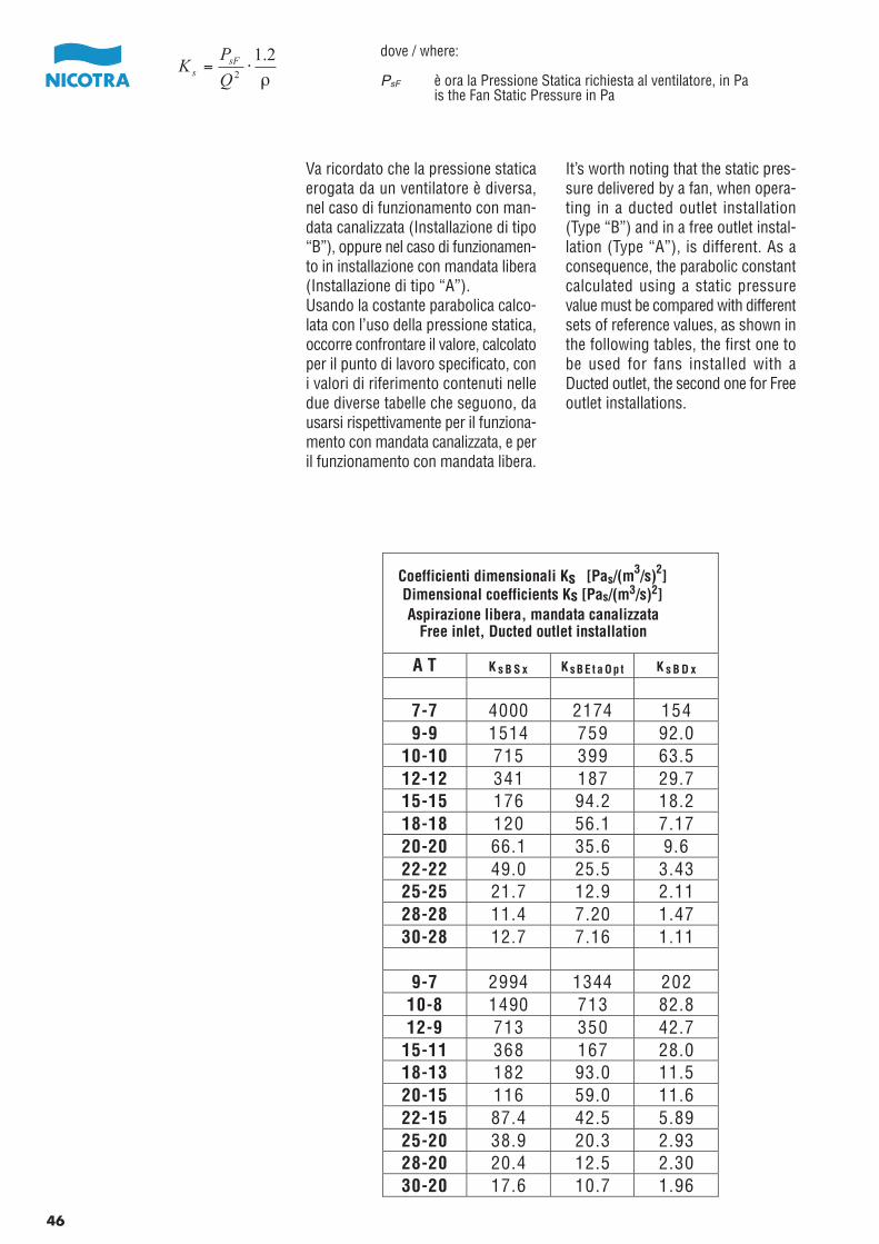
It’s worth noting that the static pres-sure delivered by a fan, when opera-ting in a ducted outlet installation(Type “B”) and in a free outlet instal-lation (Type “A”), is different. As aconsequence, the parabolic constantcalculated using a static pressurevalue must be compared with differentsets of reference values, as shown inthe following tables, the first one tobe used for fans installed with aDucted outlet, the second one for Freeoutlet installations.
Va ricordato che la pressione staticaerogata da un ventilatore è diversa,nel caso di funzionamento con man-data canalizzata (Installazione di tipo“B”), oppure nel caso di funzionamen-to in installazione con mandata libera(Installazione di tipo “A”).Usando la costante parabolica calco-lata con l’uso della pressione statica,occorre confrontare il valore, calcolatoper il punto di lavoro specificato, coni valori di riferimento contenuti nelledue diverse tabelle che seguono, dausarsi rispettivamente per il funziona-mento con mandata canalizzata, e peril funzionamento con mandata libera.
dove / where:
PsF è ora la Pressione Statica richiesta al ventilatore, in Pais the Fan Static Pressure in Pa
A T K s B S x K sB E t a Op t K s B D x
7-7 4000 2174 1549-9 1514 759 92.0
10-10 715 399 63.512-12 341 187 29.715-15 176 94.2 18.218-18 120 56.1 7.1720-20 66.1 35.6 9.622-22 49.0 25.5 3.4325-25 21.7 12.9 2.1128-28 11.4 7.20 1.4730-28 12.7 7.16 1.11
9-7 2994 1344 20210-8 1490 713 82.812-9 713 350 42.7
15-11 368 167 28.018-13 182 93.0 11.520-15 116 59.0 11.622-15 87.4 42.5 5.8925-20 38.9 20.3 2.9328-20 20.4 12.5 2.3030-20 17.6 10.7 1.96
Coefficienti dimensionali Ks [Pas/(m3/s)2]
Dimensional coefficients Ks [Pas/(m3/s)2]Aspirazione libera, mandata canalizzata
Free inlet, Ducted outlet installation
46
ρ
2.12⋅=
Q
PK sFs
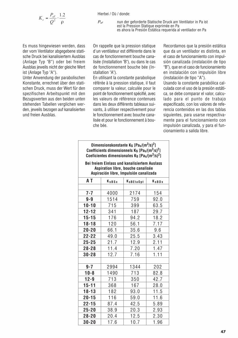
Es muss hingewiesen werden, dassder vom Ventilator abgegebene stati-sche Druck bei kanalisiertem Ausblas(Anlage Typ "B“) oder bei freiemAusblas jeweils nicht der gleiche Wertist (Anlage Typ "A“).Unter Anwendung der parabolischenKonstante, errechnet über den stati-schen Druck, muss der Wert für denspezifischen Arbeitspunkt mit denBezugswerten aus den beiden untenstehenden Tabellen verglichen wer-den, jeweils bezogen auf kanalisiertenund freien Ausblas.
On rappelle que la pression statiqued'un ventilateur est différente dans lecas de fonctionnement bouche cana-lisée (Installation "B"), ou dans le casde fonctionnement bouche bée (In-stallation "A").En utilisant la constante paraboliqueréférée à la pression statique, il fautcomparer la valeur, calculée pour lepoint de fonctionnement spécifié, avecles valeurs de référence contenuesdans les deux différents tableaux sui-vants, à utiliser respectivement pourle fonctionnement avec bouche cana-lisée et pour le fonctionnement à bou-che bée.
Recordamos que la presión estáticaque da un ventilador es distinta, enel caso de funcionamiento con impul-sión canalizada (instalación de tipo“B”), que en el caso de funcionamientoen instalación con impulsión libre(instalación de tipo “A”).Usando la constante parabólica cal-culada con el uso de la presión estáti-ca, se debe comparar el valor, calcu-lado para el punto de trabajoespecificado, con los valores de refe-rencia contenidos en las dos tablassiguientes, para usarse respectiva-mente para el funcionamiento conimpulsión canalizada, y para el fun-cionamiento a salida libre.
Hierbei / Où / donde:
PsF nun der geforderte Statische Druck am Ventilator in Pa istest la Pression Statique exprimée en Paes ahora la Presión Estática requerida al ventilador en Pa
Dimensionskonstante Ks [Pas/(m3/s)2]Coefficients dimensionnels Ks [Pas/(m3/s)2]Coeficientes dimensionales Ks [Pas/(m3/s)2]
Bei freiem Einlass und kanalisiertem AuslassAspiration libre, bouche canalisée
Aspiración libre, Impulsión canalizada
A T K s B S x K sB E t a Op t K s B D x
7-7 4000 2174 1549-9 1514 759 92.0
10-10 715 399 63.512-12 341 187 29.715-15 176 94.2 18.218-18 120 56.1 7.1720-20 66.1 35.6 9.622-22 49.0 25.5 3.4325-25 21.7 12.9 2.1128-28 11.4 7.20 1.4730-28 12.7 7.16 1.11
9-7 2994 1344 20210-8 1490 713 82.812-9 713 350 42.7
15-11 368 167 28.018-13 182 93.0 11.520-15 116 59.0 11.622-15 87.4 42.5 5.8925-20 38.9 20.3 2.9328-20 20.4 12.5 2.3030-20 17.6 10.7 1.96
47
ρ
2.12⋅=
Q
PK sFs

Again, the most appropriate fan sizeis the one with the smallest parabolicconstant at best efficiency (eitherKsBEtaOpt or KsAEtaOpt), larger than thevalue calculated for the required ope-rating point. The use of fans with aparabolic constant at design dutylarger than the recommended higherlimit, KsBSx or KsASx as appropriate,or smaller than the recommendedlower limit, either KsBDx or KsADx ,should be avoided. A fan size respec-tively smaller or larger can providethe specified duty in a steadier andmore efficient way. For AT fans, theadditional option of being able toswitch between a wide and a narrowsize may also be used.
Ancora una volta, la grandezza otti-male di ventilatore è quella con il piùpiccolo valore della costante parabo-lica (KsBEtaOpt oppure KsAEtaOpt, secon-do la condizione di installazione ap-plicabile all’impianto), maggiore ouguale al valore calcolato per il puntodi lavoro richiesto. L’impiego di ven-tilatori con valori della costante para-bolica calcolata maggiori dei valorilimite superiori (rispettivamente KsBSx
oppure KsASx), oppure minori dei va-lori limite inferiori (KsBDx oppure KsADx)è sconsigliato; una grandezza di ven-tilatore rispettivamente inferiore op-pure superiore può fornire le stesseprestazioni in modo più stabile edefficiente. Nel caso dei ventilatori serieAT, inoltre, non dovrebbe essere tra-scurata la possibilità di passare daun ventilatore della grandezza largaad una di pari diametro ma più stretta,oppure viceversa.
A T K s A S x K sA E t a Op t K s A D x
7-7 3753 1926 09-9 1420 666 0
10-10 634 317 012-12 310 156 015-15 157 74.8 018-18 113 48.8 020-20 61.3 30.8 522-22 45.3 21.8 025-25 19.5 10.6 028-28 10.0 5.73 030-28 11.4 5.89 0
9-7 2806 1155 1410-8 1380 602 012-9 668 305 0
15-11 339 138 018-13 168 79.1 020-15 107 50.1 322-15 80.6 35.7 025-20 35.7 17.1 028-20 18.0 10.1 030-20 15.4 8.56 0
Coefficienti dimensionali Ks [Pas/(m3/s)2]
Dimensional coefficients Ks [Pas/(m3/s)2]Aspirazione libera, mandata liberaFree inlet, Free outlet installation
48
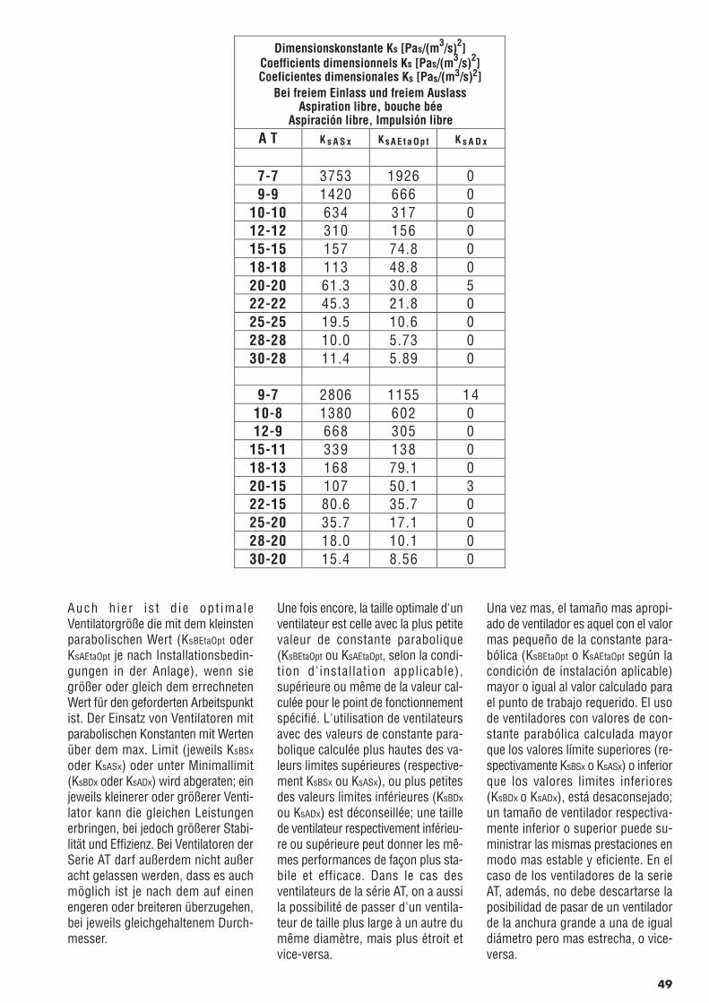
Auch h ier is t d ie opt imaleVentilatorgröße die mit dem kleinstenparabolischen Wert (KsBEtaOpt oderKsAEtaOpt je nach Installationsbedin-gungen in der Anlage), wenn siegrößer oder gleich dem errechnetenWert für den geforderten Arbeitspunktist. Der Einsatz von Ventilatoren mitparabolischen Konstanten mit Wertenüber dem max. Limit (jeweils KsBSx
oder KsASx) oder unter Minimallimit(KsBDx oder KsADx) wird abgeraten; einjeweils kleinerer oder größerer Venti-lator kann die gleichen Leistungenerbringen, bei jedoch größerer Stabi-lität und Effizienz. Bei Ventilatoren derSerie AT darf außerdem nicht außeracht gelassen werden, dass es auchmöglich ist je nach dem auf einenengeren oder breiteren überzugehen,bei jeweils gleichgehaltenem Durch-messer.
Une fois encore, la taille optimale d'unventilateur est celle avec la plus petitevaleur de constante parabolique(KsBEtaOpt ou KsAEtaOpt, selon la condi-tion d'installation applicable),supérieure ou même de la valeur cal-culée pour le point de fonctionnementspécifié. L'utilisation de ventilateursavec des valeurs de constante para-bolique calculée plus hautes des va-leurs limites supérieures (respective-ment KsBSx ou KsASx), ou plus petitesdes valeurs limites inférieures (KsBDx
ou KsADx) est déconseillée; une taillede ventilateur respectivement inférieu-re ou supérieure peut donner les mê-mes performances de façon plus sta-bile et efficace. Dans le cas desventilateurs de la série AT, on a aussila possibilité de passer d'un ventila-teur de taille plus large à un autre dumême diamètre, mais plus étroit etvice-versa.
Una vez mas, el tamaño mas apropi-ado de ventilador es aquel con el valormas pequeño de la constante para-bólica (KsBEtaOpt o KsAEtaOpt según lacondición de instalación aplicable)mayor o igual al valor calculado parael punto de trabajo requerido. El usode ventiladores con valores de con-stante parabólica calculada mayorque los valores límite superiores (re-spectivamente KsBSx o KsASx) o inferiorque los valores limites inferiores(KsBDx o KsADx), está desaconsejado;un tamaño de ventilador respectiva-mente inferior o superior puede su-ministrar las mismas prestaciones enmodo mas estable y eficiente. En elcaso de los ventiladores de la serieAT, además, no debe descartarse laposibilidad de pasar de un ventiladorde la anchura grande a una de igualdiámetro pero mas estrecha, o vice-versa.
A T K s A S x K sA E t a Op t K s A D x
7-7 3753 1926 09-9 1420 666 0
10-10 634 317 012-12 310 156 015-15 157 74.8 018-18 113 48.8 020-20 61.3 30.8 522-22 45.3 21.8 025-25 19.5 10.6 028-28 10.0 5.73 030-28 11.4 5.89 0
9-7 2806 1155 1410-8 1380 602 012-9 668 305 0
15-11 339 138 018-13 168 79.1 020-15 107 50.1 322-15 80.6 35.7 025-20 35.7 17.1 028-20 18.0 10.1 030-20 15.4 8.56 0
Dimensionskonstante Ks [Pas/(m3/s)2]Coefficients dimensionnels Ks [Pas/(m3/s)2]Coeficientes dimensionales Ks [Pas/(m3/s)2]
Bei freiem Einlass und freiem AuslassAspiration libre, bouche bée
Aspiración libre, Impulsión libre
49
GUIDELINES FOR CORRECT USE
Motor selectionAs already explained in the “Fan power”paragraph, the fan shaft power can becalculated adding together impellerpower, Wr, read on the diagram, andbearing power at the required speed,for the selected fan version, Wb, foundon the appropriate vertical scale at theright of the diagram.The minimum motor power, requiredto drive the fan, can be calculated mul-tiplying this fan shaft power by a coef-ficient (function of the shaft powervalue) which includes both the belt drivepower loss, and a reasonable safetymargin. This safety margin covers anysmall change in the operating point orin the actual fan speed, which may bedue to a motor speed or to a drive ratioslightly different from their design va-lues.
The safety coefficients may be reducedif the actual operating point is preciselyknown, and the belt drive loss can beaccurately calculated.When using motors with power largerthan 7.5 kW, it is advisable the use ofa star/delta (Y/ A) starting device, or asoft-starter. This is required to keepdown the maximum starting currentand to reduce the noise from the beltdrive at start-up, but also to reduce themechanical stress imposed on the im-pellers.
RACCOMANDAZIONI DI IMPIEGO
Scelta del motoreCome già indicato nel paragrafo relativoalla potenza assorbita, la potenza assor-bita all’albero si ottiene sommando lapotenza al mozzo della ventola Wr , lettasul diagramma, alla potenza dissipatadai cuscinetti Wb, letta, in corrisponden-za della velocità di esercizio, sulla scalaverticale della versione prescelta e col-locata alla destra del diagramma.La potenza minima del motore da in-stallare si ottiene moltiplicando la po-tenza assorbita all’albero così ottenuta,per un opportuno coefficiente, dipen-dente dal valore della potenza assorbita,che tiene conto sia delle perdite dellatrasmissione che di un ragionevolemargine di sicurezza, per fronteggiarepiccoli cambiamenti imprevisti del puntodi lavoro, o leggeri cambiamenti dellavelocità di rotazione del ventilatoreprodotti dalla diversa velocità del motoreimpiegato o dalla necessità di usare unrapporto di trasmissione leggermentediverso da quello teorico.
I coefficienti di sicurezza possono essereulteriormente ridotti nel caso in cui sianoto con precisione il punto di lavorodel ventilatore e si possa effettuare uncalcolo accurato della potenza dissipatadalla trasmissione.Nel caso di impiego di motori con po-tenza superiore a 7.5 kW, si raccomandal’uso di avviamenti a stella triangolo (Y/A) o di dispositivi di avviamento pro-gressivo. Questo è essenziale, oltre cheper contenere l’assorbimento di correnteda parte del motore e per limitare ilrumore della trasmissione allo spunto,anche per limitare le sollecitazioni mec-caniche applicate alla girante.
dove / where:
WTot è la potenza assorbita all’alberois the fan shaft power
KW è il coefficiente per la scelta del motoreis the motor selection coefficient
1 kW = 1.36 HP
per ventilatori AT:KW = 1,25 se WTot < 0,75 kWKW = 1,20 se 0,75 kW < WTot < 10 kWKW = 1,15 se WTot > 10 kW
__
for AT fans:KW = 1,25 if WTot < 0,75 kWKW = 1,20 if 0,75 kW < WTot < 10 kWKW = 1,15 if WTot > 10 kW
__
50
( )brTot WWW +=
wTotMot KWW ⋅≥
RICHTLINIEN FÜR DEN ORDNUNGS-GEMÄSSEN EINSATZ
MotorwahlWie be re i t s im Abschn i t t"Gebläseleistung“ erläutert wurde, lässtsich die Leistung für die Gebläsewelledurch Addition der Lüfterradleistung,Wr, gemäß senkrechter Skala und er-forderlicher Drehzahl für das ausgewähl-te Gebläse ermitteln, die auf der senkre-chten Skala rechts auf dem Diagrammabzulesen ist.Die Mindestmotorleistung für den An-trieb des Gebläses lässt sich durchMultiplizieren der Leistungsaufnahmeder Gebläsewelle mit einem (vom Lei-stungsbedarf der Welle abgeleiteten)Koeffizienten berechnen, der auch denLeistungsverlust für den Riemenantriebund einen angemessenen Sicherheits-bereich umfasst. Dieser Sicherheitsbe-reich deckt alle geringfügigen Lageän-derungen für den Arbeitspunkt bzw. beider tatsächlichen Gebläsedrehzahl ab,die auf dem Motorbetrieb oder einemÜbersetzungswert für den Antrieb be-ruhen, der ggf. geringfügig von denjeweiligen Auslegungswerten abweicht.
Die Sicherheitskoeffizienten lassen sichreduzieren, sofern der eigentliche Ar-beitspunkt genau bekannt ist und dieLeistungsverluste durch den Riemenan-trieb sich präzise berechnen lassen.Mit Motoren über 7,5 kW ist der Einsatzeines Stern-Dreieck-Anlassers (Y/A)bzw. eines Softstart-Anlassers sehr zuempfehlen.Dies ist wichtig um einerseits die Stro-maufnahme des Motors und die Geräu-schentwicklung am Antrieb sowiemechanische Störfaktoren am Laufradeinzuschränken.
RECOMMANDATIONSD’UTILISATION
Choix du moteurComme nous l’avons indiqué dans leparagraphe relatif à la puissance absor-bée, la puissance absorbée à l’arbre estobtenue en ajoutant à la puissance aumoyeu de la turbine Wr, lue sur la cour-be, la puissance dissipée par les roule-ments Wb, lue, en correspondance avecla vitesse d’entraînement, sur l’échelleverticale de la version prédéfinie etplacée à droite de la courbe.La puissance minimum du moteur àinstaller s’obtient en multipliant la puis-sance absorbée à l’arbre ainsi obtenuepar le bon coefficient, dépendant de lavaleur de la puissance absorbée quitient compte des pertes de la transmis-sion et d’une marge de sécurité raison-nable, pour délimiter des petits chan-gements imprévus du point defonctionnement ou de légers change-ments de la vitesse de rotation du ven-tilateur produits par la vitesse du moteurutilisé ou par la nécessité d'utiliser unrapport de transmission un peu différentde la théorie.
Les coefficients de sécurité peuventêtre ensuite réduits si l’on note avecprécision le point de fonctionnementdu ventilateur et si l’on peut effectuerun calcul précis de la puissance dissipéepar la transmission.Nous recommandons pour les moteurssupérieurs à 7,5 kW l’utilisation d’undémarrage en étoile triangle (Y/A) oude dispositifs de démarrages progres-sifs. Cela est important pour limiterl'absorption de courant par le moteuret le bruit de la transmission au démar-rage, ainsi que pour limiter les contrain-tes mécaniques qui affèctent la turbine.
RECOMANDACIONES DE USO
Selección del motorComo se ha explicado ya en el párraforelativo a la potencia absorbida, la po-tencia absorbida al eje se obtiene su-mando la potencia al núcleo de la turbinaWr, leída en el diagrama, a la potenciadisipada en los rodamientos Wb, leída,en correspondencia a la velocidad deejercicio, en la escala vertical de laversión seleccionada y colocada a laderecha del diagrama.La potencia mínima a instalar del motorse obtiene multiplicando la potenciaabsorbida en el eje así obtenida, por elcoeficiente apropiado, dependiente delvalor de la potencia absorbida, que tieneen cuenta ya sea las pérdidas de latransmisión como un razonable margende seguridad, para hacer fronte a pe-queños cambios imprevistos del puntode trabajo o ligeros cambios en la velo-cidad de rotación del ventilador produ-cidos por la diferente velocidad delmotor empleado o de la necesidad deusar una combinación de transmisiónligeramente diferente al teórico.
Los coeficientes de seguridad puedenser reducidos en el caso en que seconozca con precisión el punto de tra-bajo del ventilador y se pueda efectuarun cálculo ajustado de la potencia disi-pada en la transmisión.Para motores con potencia superior a7.5 kW, se recomienda el uso de arran-ques estrella-triángulo (Y/A) o de dispo-sitivos de arranque progresivo. Esto esesencial, además de para contener laabsorción de corriente por parte delmotor y para limitar el ruido de la tran-smisión en el arranque, también paralimitar el estrés mecánico aplicado alrodete.
hierbei ist / Où / donde;
WTot die Leistungsaufnahme an der Gebläsewelleest la puissance absorbée à l’arbrees la potencia absorbida en el eje del ventilador
KW der Koeffizient für die Motorenauswahlest le coefficient pour le choix du moteures el coeficiente para la selección del motor
für AT-Ventilatoren:KW = 1,25 bei WTot < 0,75 kWKW = 1,20 bei 0,75 kW < WTot < 10 kWKW = 1,15 bei WTot > 10 kW
__
pour les ventilateurs AT:KW = 1,25 si WTot < 0,75 kWKW = 1,20 si 0,75 kW < WTot < 10 kWKW = 1,15 si WTot > 10 kW
__
para ventiladores AT:KW = 1,25 si WTot < 0,75 kWKW = 1,20 si 0,75 kW < WTot < 10 kWKW = 1,15 si WTot > 10 kW
__
51
( )brTot WWW +=
wTotMot KWW ⋅≥
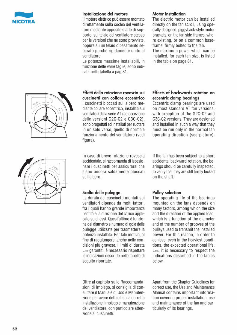
Motor InstallationThe electric motor can be installeddirectly on the fan scroll, using spe-cially designed, piggyback-style motorbrackets, on the fan side-frames, whe-re existing, or on a common base-frame, firmly bolted to the fan.The maximum power which can beinstalled, for each fan size, is listedin the table on page 81.
Effects of backwards rotation oneccentric clamp bearingsEccentric clamp bearings are usedon most standard AT fan versions,with exception of the G2C-C2 andG3C-C2 versions. They are designedand installed in such a way that theymust be run only in the normal fanoperating direction (see picture).
If the fan has been subject to a shortaccidental backward rotation, the be-arings should be carefully inspected,to verify that they are still firmly lockedon the shaft.
Pulley selectionThe operating life of the bearingsmounted on the fans depends onmany factors, among which the sizeand the direction of the applied load,which is a function of the diameterand of the number of grooves of thepulleys used to transmit the installedpower. For this reason, in order toachieve, even in the heaviest condi-tions, the expected operational life,L10h, it is necessary to respect theindications described in the tablesbelow.
Apart from the Chapter Guidelines forcorrect use, the Use and MaintenanceManual contains important informa-tion covering proper installation, useand maintenance of the fan and par-ticularly of its bearings.
Installazione del motoreIl motore elettrico può essere montatodirettamente sulla coclea del ventila-tore mediante apposite staffe di sup-porto, sul telaio del ventilatore stessoper le versioni che ne sono provviste,oppure su un telaio o basamento se-parato purché rigidamente unito alventilatore.Le potenze massime installabili, infunzione delle varie taglie, sono indi-cate nella tabella a pag.81.
Effetti della rotazione rovescia suicuscinetti con collare eccentricoI cuscinetti bloccati sull’albero me-diante collare eccentrico, installati suiventilatori della serie AT (ad eccezionedelle versioni G2C-C2 e G3C-C2),sono progettati ed installati per ruotarein un solo verso, quello di normalefunzionamento del ventilatore (vedifigura).
In caso di breve rotazione rovesciaaccidentale, si raccomanda di ispezio-nare i cuscinetti per assicurarsi chesiano ancora saldamente bloccatisull’albero.
Scelta delle puleggeLa durata dei cuscinetti montati suiventilatori dipende da molti fattori,fra i quali hanno grande importanzal’entità e la direzione del carico appli-cato su di essi. Quest’ultimo è funzio-ne del diametro e numero di gole dellepulegge utilizzate per trasmettere lapotenza installata. Per tale motivo, alfine di raggiungere, anche nelle con-dizioni più gravose, i limiti di durataL10h garantiti, è necessario rispettarele indicazioni descritte nelle tabelle diseguito riportate.
Oltre al capitolo sulle Raccomanda-zioni di Impiego, si consiglia di con-sultare il Manuale di Uso e Manuten-zione per avere dettagli sulla correttainstallazione, impiego e manutenzionedel ventilatore, con particolare atten-zione ai cuscinetti.
52
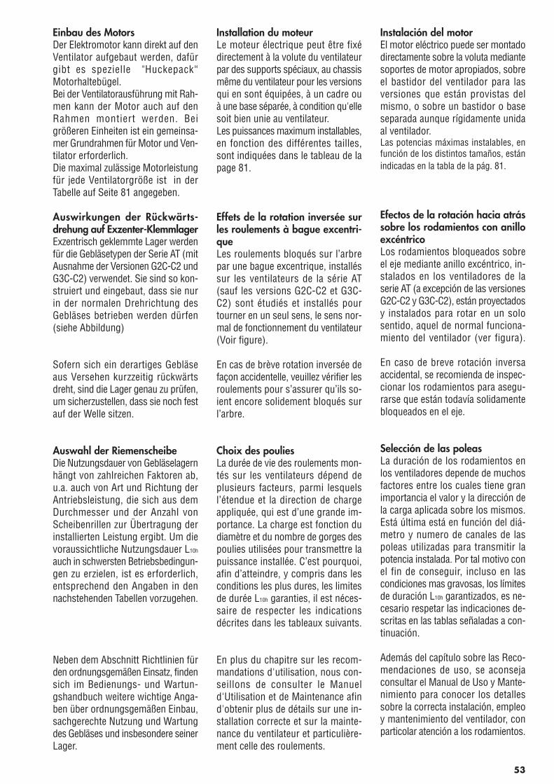
Einbau des MotorsDer Elektromotor kann direkt auf denVentilator aufgebaut werden, dafürgibt es spezielle "Huckepack“Motorhaltebügel.Bei der Ventilatorausführung mit Rah-men kann der Motor auch auf denRahmen montiert werden. Beigrößeren Einheiten ist ein gemeinsa-mer Grundrahmen für Motor und Ven-tilator erforderlich.Die maximal zulässige Motorleistungfür jede Ventilatorgröße ist in derTabelle auf Seite 81 angegeben.
Auswirkungen der Rückwärts-drehung auf Exzenter-KlemmlagerExzentrisch geklemmte Lager werdenfür die Gebläsetypen der Serie AT (mitAusnahme der Versionen G2C-C2 undG3C-C2) verwendet. Sie sind so kon-struiert und eingebaut, dass sie nurin der normalen Drehrichtung desGebläses betrieben werden dürfen(siehe Abbildung)
Sofern sich ein derartiges Gebläseaus Versehen kurzzeitig rückwärtsdreht, sind die Lager genau zu prüfen,um sicherzustellen, dass sie noch festauf der Welle sitzen.
Auswahl der RiemenscheibeDie Nutzungsdauer von Gebläselagernhängt von zahlreichen Faktoren ab,u.a. auch von Art und Richtung derAntriebsleistung, die sich aus demDurchmesser und der Anzahl vonScheibenrillen zur Übertragung derinstallierten Leistung ergibt. Um dievoraussichtliche Nutzungsdauer L10h
auch in schwersten Betriebsbedingun-gen zu erzielen, ist es erforderlich,entsprechend den Angaben in dennachstehenden Tabellen vorzugehen.
Neben dem Abschnitt Richtlinien fürden ordnungsgemäßen Einsatz, findensich im Bedienungs- und Wartun-gshandbuch weitere wichtige Anga-ben über ordnungsgemäßen Einbau,sachgerechte Nutzung und Wartungdes Gebläses und insbesondere seinerLager.
Installation du moteurLe moteur électrique peut être fixédirectement à la volute du ventilateurpar des supports spéciaux, au chassismême du ventilateur pour les versionsqui en sont équipées, à un cadre ouà une base séparée, à condition qu'ellesoit bien unie au ventilateur.Les puissances maximum installables,en fonction des différentes tailles,sont indiquées dans le tableau de lapage 81.
Effets de la rotation inversée surles roulements à bague excentri-queLes roulements bloqués sur l’arbrepar une bague excentrique, installéssur les ventilateurs de la série AT(sauf les versions G2C-C2 et G3C-C2) sont étudiés et installés pourtourner en un seul sens, le sens nor-mal de fonctionnement du ventilateur(Voir figure).
En cas de brève rotation inversée defaçon accidentelle, veuillez vérifier lesroulements pour s’assurer qu’ils so-ient encore solidement bloqués surl’arbre.
Choix des pouliesLa durée de vie des roulements mon-tés sur les ventilateurs dépend deplusieurs facteurs, parmi lesquelsl’étendue et la direction de chargeappliquée, qui est d’une grande im-portance. La charge est fonction dudiamètre et du nombre de gorges despoulies utilisées pour transmettre lapuissance installée. C’est pourquoi,afin d’atteindre, y compris dans lesconditions les plus dures, les limitesde durée L10h garanties, il est néces-saire de respecter les indicationsdécrites dans les tableaux suivants.
En plus du chapitre sur les recom-mandations d'utilisation, nous con-seillons de consulter le Manueld'Utilisation et de Maintenance afind'obtenir plus de détails sur une in-stallation correcte et sur la mainte-nance du ventilateur et particulière-ment celle des roulements.
Instalación del motorEl motor eléctrico puede ser montadodirectamente sobre la voluta mediantesoportes de motor apropiados, sobreel bastidor del ventilador para lasversiones que están provistas delmismo, o sobre un bastidor o baseseparada aunque rígidamente unidaal ventilador.Las potencias máximas instalables, enfunción de los distintos tamaños, estánindicadas en la tabla de la pág. 81.
Efectos de la rotación hacia atrássobre los rodamientos con anilloexcéntricoLos rodamientos bloqueados sobreel eje mediante anillo excéntrico, in-stalados en los ventiladores de laserie AT (a excepción de las versionesG2C-C2 y G3C-C2), están proyectadosy instalados para rotar en un solosentido, aquel de normal funciona-miento del ventilador (ver figura).
En caso de breve rotación inversaaccidental, se recomienda de inspec-cionar los rodamientos para asegu-rarse que están todavía solidamentebloqueados en el eje.
Selección de las poleasLa duración de los rodamientos enlos ventiladores depende de muchosfactores entre los cuales tiene granimportancia el valor y la dirección dela carga aplicada sobre los mismos.Está última está en función del diá-metro y numero de canales de laspoleas utilizadas para transmitir lapotencia instalada. Por tal motivo conel fin de conseguir, incluso en lascondiciones mas gravosas, los límitesde duración L10h garantizados, es ne-cesario respetar las indicaciones de-scritas en las tablas señaladas a con-tinuación.
Además del capítulo sobre las Reco-mendaciones de uso, se aconsejaconsultar el Manual de Uso y Mante-nimiento para conocer los detallessobre la correcta instalación, empleoy mantenimiento del ventilador, conparticolar atención a los rodamientos.
53
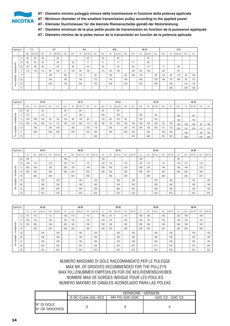
S-SC-Cubik-G2L-SC2 AR-TIC-G2C-G3C G2C C2 - G3C C2
N° DI GOLEN° OF GROOVES
2 3 4
VERSIONE - VERSION
NUMERO MASSIMO DI GOLE RACCOMANDATO PER LE PULEGGEMAX NR. OF GROOVES RECOMMENDED FOR THE PULLEYS
NOMBRE MAX DE GORGES INDIQUE POUR LES POULIESMAX RILLENUMMER EMPFOHLEN FÜR DIE KEILRIEMENSCHEIBEN
NUMERO MAXIMO DE CANALES ACONSEJADO PARA LAS POLEAS
AT - Minimum diameter of the smallest transmission pulley according to the applied power
AT - Diámetro minimo de la polea menor de la transmisión en función de la potencia aplicada
AT - Diametro minimo puleggia minore della trasmissione in funzione della potenza applicata
AT - Kleinster Durchmesser für die kleinste Riemenscheibe gemäß der Motorleistung
AT - Diamètre minimum de la plus petite poulie de transmission en fonction de la puissance appliquée
S/SC G2L/SC2 S/SC AR G2L/SC2 G2C S/SC AR G2L/SC2 G2C S/SC AR G2L/SC2 G2C S/SC AR G2L/SC2 G2C S/SC AR G2L/SC2 G2C G3C
1,1 63 63 63 63 63 63 63 63
1,5 63 63 63 63 63 71 71 71 71 80
2,2 80 90 85 90 90 95 85 95 95 112 71 85
3 112 118 112 80 125 71 125 85 132 112 80 132 125 85 140 90 95
4 100 80 112 80 100 80 180 118 90 118 85 118 80 100
5,5 140 100 150 112 150 100 160 125 180 118 180 90 112
7,5 200 150 224 150 200 150 224 180 160 118 118
11 236 224 180
12-97-7 9-7 9-9 10-8 10-10Taglia/size
Kw In
stal
lati
/ Ins
talle
d Kw
S/SC AR G2L/SC2 G2C G3C S/SC AR G2L/SC2 G2C G3C S/SC AR G2L/SC2 G2C G3C S/SC AR G2L/SC2 G2C G3C S/SC AR G2L/SC2 G2C G3C
2,2 90 80 85 80 80 80
3 112 112 112 100 100 100 100 95 100 90
4 140 100 140 85 90 132 90 140 85 132 95 132 85 132 125 132 118
5,5 200 140 200 112 112 180 118 200 112 100 180 132 180 100 100 180 100 180 95 100 180 100 180 95 100
7,5 190 140 140 160 150 118 180 132 118 250 140 250 112 112 250 132 224 112 112
11 280 200 200 236 224 180 250 200 160 200 160 160 190 160 140
15 250 224 280 224 224 280 224 200
18-1812-12 15-11 15-15 18-13Taglia/size
Kw In
stal
lati
/ Ins
talle
d Kw
TIC G2C G2C Cl2 G3C G3C Cl2 TIC G2C G2C Cl2 G3C G3C Cl2 TIC G2C G2C Cl2 G3C G3C Cl2 TIC G2C G2C Cl2 G3C G3C Cl2 TIC G2C G2C Cl2 G3C G3C Cl2
5,5 100 100 100 100 90
7,5 140 112 112 132 112 112 132 112 112 132 112 112 118 112 112
11 200 160 150 200 150 140 200 160 140 200 150 140 160 140 132
15 280 250 200 280 224 200 280 224 200 280 224 200 224 200 200
19 280 280 250 250 280 250 280 250 250 224
22 150 150 150 150 150 150 150 150 150 150
30 180 180 180 180 180 180 180 180 180 180
37 200 200 200 200 200 200 200 190 190 190
45 224 224 224 224 224 224 224 224 224 224
25-20Taglia/size 20-15 20-20 22-15 22-22
Kw In
stal
lati
/ Ins
talle
d Kw
TIC G2C G2C Cl2 G3C G3C Cl2 TIC G2C G2C Cl2 G3C G3C Cl2 TIC G2C G2C Cl2 G3C G3C Cl2 TIC G2C G2C Cl2 G3C G3C Cl2 TIC G2C G2C Cl2 G3C G3C Cl2
7,5 112 112 112 100 112 112 100 112 112 100 100 100 100 100 100
11 150 140 132 150 132 132 140 132 125 140 132 125 140 125 125
15 224 200 180 200 180 180 200 180 160 200 180 180 200 180 160
19 250 224 250 224 224 250 224 200 250 224 224 250 224 200
22 150 150 150 150 150 150 150 150 150 150
30 180 180 180 180 180 180 180 180 180 180
37 190 190 190 190 190 190 190 190 190 190
45 224 224 224 224 224 224 212 224 212 224
55 224 224 224 224 224 224 224 224 224 224
Taglia/size 25-25 28-20 28-28 30-20 30-28
Kw In
stal
lati
/ Ins
talle
d Kw
54
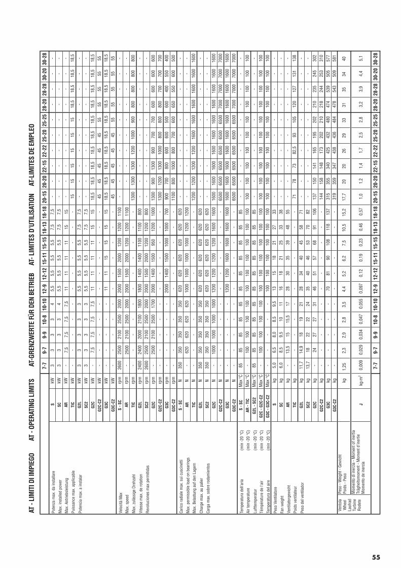
AT -
LIM
ITI D
I IM
PIEG
O
A
T - O
PERA
TING
LIM
ITS
AT-
GREN
ZWER
TE F
R DE
N BE
TRIE
B
AT-
LIM
ITES
D’U
TILI
SATI
ON
AT-
LIM
ITES
DE
EMPL
EO
7-7
9-7
9-9
10-8
10-1
012
-912
-12
15-1
115
-15
18-1
318
-18
20-1
520
-20
22-1
522
-22
25-2
025
-25
28-2
028
-28
30-2
030
-28
Pote
nza
max
. da
inst
alla
reS
kW3
33
34
5,5
5,5
5,5
5,5
7,5
7,5
--
--
--
--
--
Max
. ins
talle
d po
wer
SCkW
33
33
45,
55,
55,
55,
57,
57,
5-
--
--
--
--
-
Max
. Ant
riebs
leis
tung
ARkW
-7,
57,
57,
57,
511
1111
1115
15-
--
--
--
--
-
Puis
sanc
e m
ax. a
pplic
able
TIC
kW-
--
--
--
--
--
1515
1515
1515
18,5
18,5
18,5
18,5
Pote
ncia
max
. a in
stal
arG
2LkW
33
33
35,
55,
55,
55,
57,
57,
5-
--
--
--
--
-
SC2
kW3
33
33
5,5
5,5
5,5
5,5
7,5
7,5
--
--
--
--
--
G2C
kW-
7,5
7,5
7,5
7,5
1111
1111
1515
18,5
18,5
18,5
18,5
18,5
18,5
18,5
18,5
18,5
18,5
G2C
-C2
kW-
--
--
--
--
--
4545
4545
4555
5555
5555
G3C
kW-
--
--
1111
1515
1515
18,5
18,5
18,5
18,5
18,5
18,5
18,5
18,5
18,5
18,5
G3C
-C2
kW-
--
--
--
--
--
4545
4545
4555
5555
5555
Velo
cità
Max
S - S
Crp
m26
0025
0021
0025
0020
0020
0015
0020
0012
0012
0011
00-
--
--
--
--
-
Max
. spe
edAR
rpm
-25
0021
0025
0020
0020
0015
0020
0012
0012
0011
00-
--
--
--
--
Max
. zul
ässi
ge D
rehz
ahl
TIC
rpm
--
--
--
--
--
-13
0013
0013
0012
0010
0090
080
080
080
080
0
Vite
sse
max
. de
rota
tion
G2L
rpm
2400
2400
2000
2100
1800
1800
1400
1400
1100
1100
800
--
--
--
--
--
Rev
oluc
ione
s m
ax p
erm
itida
sSC
2rp
m26
0025
0021
0025
0020
0020
0015
0020
0012
0012
0080
0-
--
--
--
--
-
G2C
rpm
-25
0021
0025
0017
0020
0014
0015
0095
012
0010
0013
0090
013
0090
070
070
060
060
060
060
0
G2C
-C2
rpm
--
--
--
--
--
-13
0012
0013
0010
0080
080
080
070
070
070
0
G3C
rpm
--
--
-20
0014
0015
0010
0010
0070
090
070
080
060
060
050
060
040
055
040
0
G3C
-C2
rpm
--
--
--
--
--
-11
0080
010
0080
070
060
065
055
060
050
0
Caric
o ra
dial
e m
ax. s
ui c
usci
netti
S - S
CN
350
350
350
350
350
620
620
620
620
620
620
--
--
--
--
--
Max
. per
mis
sibl
e lo
ad o
n be
arin
gsAR
N-
620
620
620
620
1000
1000
1000
1000
1200
1200
--
--
--
--
--
Max
. Bel
astu
ng a
uf d
en L
ager
nTI
CN
--
--
--
--
--
-12
0012
0012
0012
0016
0016
0016
0016
0016
0016
00
Char
ge m
ax. a
u pa
lier
G2L
N35
035
035
035
035
062
062
062
062
062
062
0-
--
--
--
--
-
Carg
a m
ax. s
obre
roda
mie
ntos
SC2
N35
035
035
035
035
062
062
062
062
062
062
0-
--
--
--
--
-
G2C
N-
1000
1000
1000
1000
1200
1200
1200
1200
1600
1600
1600
1600
1600
1600
1600
1600
1600
1600
1600
1600
G2C
-C2
N-
--
--
--
--
--
6500
6500
6500
6500
6500
6500
7000
7000
7000
7000
G3C
N-
--
--
1200
1200
1600
1600
1600
1600
1600
1600
1600
1600
1600
1600
1600
1600
1600
1600
G3C
-C2
N-
--
--
--
--
--
6500
6500
6500
6500
6500
6500
7000
7000
7000
7000
Tem
pera
tura
del
l'aria
(min
-20 °C
)S
- SC
Max
°C85
8585
8585
8585
8585
8585
--
--
--
--
--
Air t
empe
ratu
re(m
in -2
0 °C
)AR
- TI
CM
ax °C
-10
010
010
010
010
010
010
010
010
010
010
010
010
010
010
010
010
010
010
010
0
Luftt
empe
ratu
r(m
in -2
0 °C
)G
2L -
SC2
Max
°C85
8585
8585
8585
8585
8585
--
--
--
--
--
Tém
péra
ture
de
l'air
(min
-20 °C
)G
2C -
G2C
-C2
Max
°C-
100
100
100
100
100
100
100
100
100
100
100
100
100
100
100
100
100
100
100
100
Tem
pera
tura
del
aire
(min
-20 °C
)G
3C -
G3C
-C2
Max
°C
--
--
-10
010
010
010
010
010
010
010
010
010
010
010
010
010
010
010
0
Peso
Ven
tilat
ore
Skg
5,0
6,5
8,0
8,5
9,5
1315
1821
2733
--
--
--
--
--
Fan
wei
ght
SCkg
6,0
8,5
9,5
1011
1618
2125
3338
--
--
--
--
--
Vent
ilato
rgew
icht
ARkg
-13
,515
15,5
1728
3035
3948
55-
--
--
--
--
-
Poid
s ve
ntila
teur
TIC
kg-
--
--
--
--
--
7178
7382
,593
105
120
127
131
138
Peso
del
ven
tilad
orG
2Lkg
11,7
14,9
1819
2128
3440
4558
71-
--
--
--
--
-
SC2
kg13
,718
2222
2435
4046
5370
82-
--
--
--
--
-
G2C
kg-
2427
2731
4651
5768
9110
613
715
014
116
519
520
221
023
524
530
2
G2C
-C2
kg-
--
--
--
--
--
144
158
148
173
202
210
218
244
253
310
G3C
kg-
--
--
7081
9010
811
813
731
535
534
042
543
248
047
453
950
557
7G
3C-C
2kg
--
--
--
--
--
-31
935
934
743
843
648
447
854
350
958
1
kg1,
252,
32,
92,
83,
54,
45,
26,
27,
510
,515
,217
,720
2026
2933
3135
3440
Jkg
·m2
0,00
90,
029
0,03
40,
047
0,05
50,
097
0,12
0,19
0,23
0,46
0,57
1,0
1,2
1,4
1,7
2,5
2,8
3,2
3,9
4,4
5,1
7-7
9-7
9-9
10-8
10-1
012
-912
-12
15-1
115
-15
18-1
318
-18
20-1
520
-20
22-1
522
-22
25-2
025
-25
28-2
028
-28
30-2
030
-28
Vent
ola
Whe
elLa
ufra
dTu
rbin
eR
odet
e
Peso
- W
eigh
t - G
ewic
htPo
ids
- Pes
o
Mom
ento
di i
nerz
ia -
Mom
ent o
f ine
rtia
Träg
heits
mom
ent -
Mom
ent d
'iner
tieM
omen
to d
e in
erci
a
55
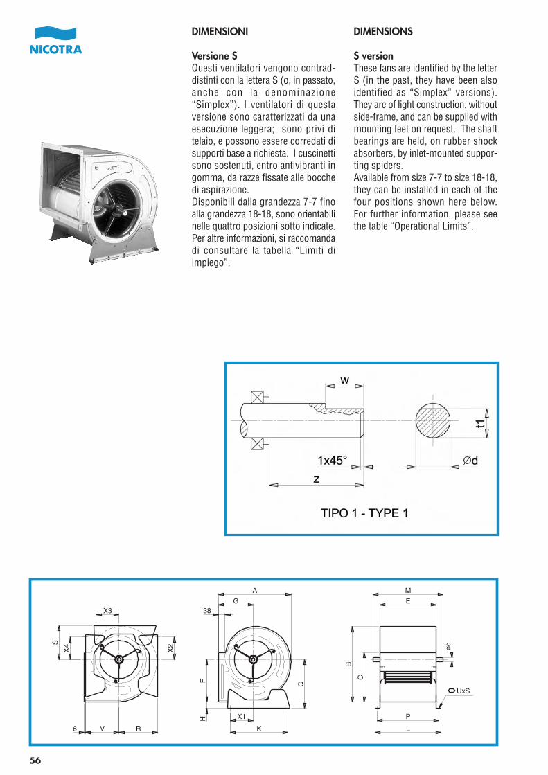
Pag.56-57-58-59_Cat_AT 06.fh11 21-04-2006 10:30 Pagina 1
C M Y CM MY CY CMY K
56
DIMENSIONS
S versionThese fans are identified by the letterS (in the past, they have been alsoidentified as “Simplex” versions).They are of light construction, withoutside-frame, and can be supplied withmounting feet on request. The shaftbearings are held, on rubber shockabsorbers, by inlet-mounted suppor-ting spiders.Available from size 7-7 to size 18-18,they can be installed in each of thefour positions shown here below.For further information, please seethe table “Operational Limits”.
DIMENSIONI
Versione SQuesti ventilatori vengono contrad-distinti con la lettera S (o, in passato,anche con la denominazione“Simplex”). I ventilatori di questaversione sono caratterizzati da unaesecuzione leggera; sono privi ditelaio, e possono essere corredati disupporti base a richiesta. I cuscinettisono sostenuti, entro antivibranti ingomma, da razze fissate alle bocchedi aspirazione.Disponibili dalla grandezza 7-7 finoalla grandezza 18-18, sono orientabilinelle quattro posizioni sotto indicate.Per altre informazioni, si raccomandadi consultare la tabella “Limiti diimpiego”.
M
E
ød
P
L
G38
A
F Q
H
K
X1
B
C
6 RV
X2
X3
S
X4
UxS
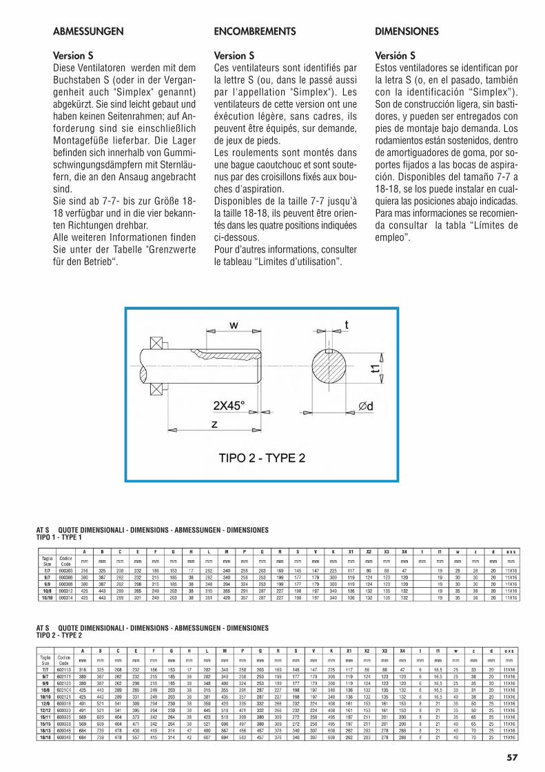
Pag.56-57-58-59_Cat_AT 06.fh11 21-04-2006 10:30 Pagina 2
C M Y CM MY CY CMY K
57
ABMESSUNGEN
Version SDiese Ventilatoren werden mit demBuchstaben S (oder in der Vergan-genheit auch "Simplex" genannt)abgekürzt. Sie sind leicht gebaut undhaben keinen Seitenrahmen; auf An-forderung sind sie einschließlichMontagefüße lieferbar. Die Lagerbefinden sich innerhalb von Gummi-schwingungsdämpfern mit Sternläu-fern, die an den Ansaug angebrachtsind.Sie sind ab 7-7- bis zur Größe 18-18 verfügbar und in die vier bekann-ten Richtungen drehbar.Alle weiteren Informationen findenSie unter der Tabelle "Grenzwertefür den Betrieb“.
ENCOMBREMENTS
Version SCes ventilateurs sont identifiés parla lettre S (ou, dans le passé aussipar l'appellation "Simplex"). Lesventilateurs de cette version ont uneéxécution légère, sans cadres, ilspeuvent être équipés, sur demande,de jeux de pieds.Les roulements sont montés dansune bague caoutchouc et sont soute-nus par des croisillons fixés aux bou-ches d'aspiration.Disponibles de la taille 7-7 jusqu’àla taille 18-18, ils peuvent être orien-tés dans les quatre positions indiquéesci-dessous.Pour d’autres informations, consulterle tableau “Limites d’utilisation”.
DIMENSIONES
Versión SEstos ventiladores se identifican porla letra S (o, en el pasado, tambiéncon la identificación “Simplex”).Son de construcción ligera, sin basti-dores, y pueden ser entregados conpies de montaje bajo demanda. Losrodamientos están sostenidos, dentrode amortiguadores de goma, por so-portes fijados a las bocas de aspira-ción. Disponibles del tamaño 7-7 a18-18, se los puede instalar en cual-quiera las posiciones abajo indicadas.Para mas informaciones se recomien-da consultar la tabla “Límites deempleo”.
AT S QUOTE DIMENSIONALI - DIMENSIONS - ABMESSUNGEN - DIMENSIONESTIPO 1 - TYPE 1
AT S QUOTE DIMENSIONALI - DIMENSIONS - ABMESSUNGEN - DIMENSIONESTIPO 2 - TYPE 2
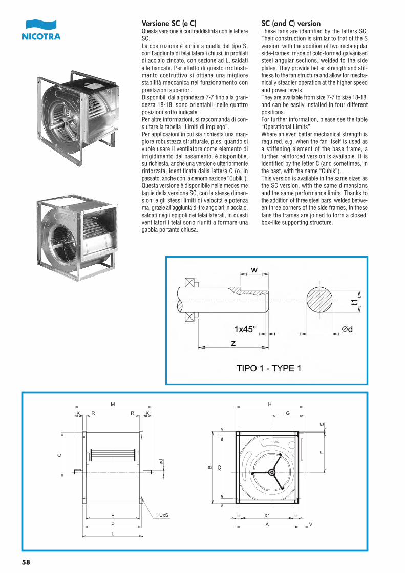
Pag.56-57-58-59_Cat_AT 06.fh11 21-04-2006 10:30 Pagina 3
C M Y CM MY CY CMY K
58
KK
M
C
E
P
=
SF
UxS
RR
L
B
=
A V
= =
H
G
X1
X2
Versione SC (e C)Questa versione è contraddistinta con le lettereSC.La costruzione è simile a quella del tipo S,con l’aggiunta di telai laterali chiusi, in profilatidi acciaio zincato, con sezione ad L, saldatialle fiancate. Per effetto di questo irrobusti-mento costruttivo si ottiene una migliorestabilità meccanica nel funzionamento conprestazioni superiori.Disponibili dalla grandezza 7-7 fino alla gran-dezza 18-18, sono orientabili nelle quattroposizioni sotto indicate.Per altre informazioni, si raccomanda di con-sultare la tabella “Limiti di impiego”.Per applicazioni in cui sia richiesta una mag-giore robustezza strutturale, p.es. quando sivuole usare il ventilatore come elemento diirrigidimento del basamento, è disponibile,su richiesta, anche una versione ulteriormenterinforzata, identificata dalla lettera C (o, inpassato, anche con la denominazione “Cubik”).Questa versione è disponibile nelle medesimetaglie della versione SC, con le stesse dimen-sioni e gli stessi limiti di velocità e potenzama, grazie all’aggiunta di tre angolari in acciaio,saldati negli spigoli dei telai laterali, in questiventilatori i telai sono riuniti a formare unagabbia portante chiusa.
SC (and C) versionThese fans are identified by the letters SC.Their construction is similar to that of the Sversion, with the addition of two rectangularside-frames, made of cold-formed galvanisedsteel angular sections, welded to the sideplates. They provide better strength and stif-fness to the fan structure and allow for mecha-nically steadier operation at the higher speedand power levels.They are available from size 7-7 to size 18-18,and can be easily installed in four differentpositions.For further information, please see the table“Operational Limits”.Where an even better mechanical strength isrequired, e.g. when the fan itself is used asa stiffening element of the base frame, afurther reinforced version is available. It isidentified by the letter C (and sometimes, inthe past, with the name “Cubik”).This version is available in the same sizes asthe SC version, with the same dimensionsand the same performance limits. Thanks tothe addition of three steel bars, welded betwe-en three corners of the side frames, in thesefans the frames are joined to form a closed,box-like supporting structure.
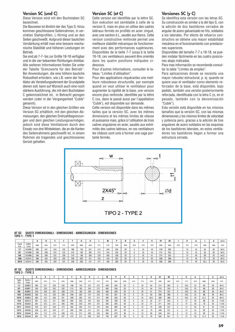
Pag.56-57-58-59_Cat_AT 06.fh11 21-04-2006 10:30 Pagina 4
C M Y CM MY CY CMY K
59
Version SC (und C)Diese Version wird mit den Buchstaben SCbezeichnet.Die Bauweise ist ähnlich der des Typs S; hinzukommen geschlossene Seitenrahmen, in ver-zinkten Stahlprofilen, L-förmig und an denSeiten geschweißt. Aufgrund dieser baulichenVerstärkung erhält man eine bessere mecha-nische Stabilität und höheren Leistungen imBetrieb.Sie sind ab 7-7- bis zur Größe 18-18 verfügbarund in die vier bekannten Richtungen drehbar.Alle weiteren Informationen finden Sie unterder Tabelle "Grenzwerte für den Betrieb“.Bei Anwendungen, die eine höhere baulicheRobustheit erfordern, wie z.B. wenn der Ven-tilator als Versteifungselement der Grundplattedienen soll, kann auf Wunsch auch eine nochstärkere Ausführung, die mit dem BuchstabenC gekennzeichnet ist, in Betracht gezogenwerden (oder in der Vergangenheit "Cubik“genannt).Diese Version ist in den gleichen Größen wieVersion SC erhältlich, mit den gleichen Ab-messungen, den gleichen Drehzahlbegrenzun-gen und dem gleichen Leistungsvermögen,jedoch sind diese Ventilatoren durch denEinsatz von drei Winkeleisen, die an die Kantendes Seitenrahmens geschweißt ist, in einemRahmen als tragendes und geschlossenesGerüst gehalten.
Version SC (et C)Cette version est identifiée par la lettre SC.Son exécution est semblable à celle de laversion S, mais en plus on utilise des cadreslatéraux fermés en profilés en acier zingué,avec une section à L, saudés aux flancs. Cetteversion constructive renforcée permet unemeilleure stabilité mécanique de fonctionne-ment avec des performances supérieures.Disponibles de la taille 7-7 jusqu’à la taille18-18, ces ventilateurs peuvent être orientésdans les quatre positions indiquées ci-dessous.Pour d’autres informations, consulter le ta-bleau “Limites d’utilisation”.Pour des applications requérantes une meil-leure robustesse structurelle, par exemplequand on veut utiliser le ventilateur pouraugmenter la rigidité de la base, une versionencore plus renforcée, identifiée par la lettreC (ou, dans le passé aussi par l'appellation"Cubik"), est disponible sur demande.Cette version est disponible dans les mêmestailles que la version SC, avec les mêmesdimensions et les mêmes limites de vitesseet puissance mais, grâce à l'utilisation de troiscadres angulaires en acier, saudés aux extré-mités des cadres latéraux, en ces ventilateursles châssis sont unis à former une cage por-tante fermée.
Versiones SC (y C)Se identifica esta versión con las letras SC.Su construcción es similar a la del tipo S, conla adición de dos bastidores cerrados deangular de acero galvanizado en frío, soldadosa los laterales. Por efecto de refuerzo con-structivo se obtiene una mayor estabilidadmecánica en el funcionamiento con prestacio-nes superiores.Disponibles del tamaño 7-7 a 18-18, se pue-den instalar fácilmente en las cuatro posicio-nes abajo indicadas.Para mas información se recomienda consul-tar la tabla “Límites de empleo”.Para aplicaciones donde se necesita unamayor robustez estructural, p. ej. quando sequiere usar el ventilador como elemento re-forzador de la base, está disponible, bajopedido, también una versión posteriormentereforzada, identificada con la letra C (o, en elpasado, también con la denominación“Cubik”).Esta versión está disponible en los mismostamaños que la versión SC, con las mismasdimensiones y los mismos limites de velocidady potencia pero, gracias a la adición de tresangulares de acero soldados en las esquinasde los bastidores laterales, en estos ventila-dores los bastidores llegan a formar unaestructura cerrada.
AT SC QUOTE DIMENSIONALI - DIMENSIONS - ABMESSUNGEN - DIMENSIONESTIPO 1 - TYPE 1
AT SC QUOTE DIMENSIONALI - DIMENSIONS - ABMESSUNGEN - DIMENSIONESTIPO 2 - TYPE 2
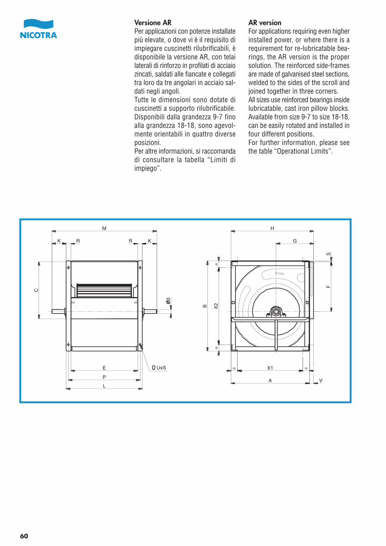
AR versionFor applications requiring even higherinstalled power, or where there is arequirement for re-lubricatable bea-rings, the AR version is the propersolution. The reinforced side-framesare made of galvanised steel sections,welded to the sides of the scroll andjoined together in three corners.All sizes use reinforced bearings insidelubricatable, cast iron pillow blocks.Available from size 9-7 to size 18-18,can be easily rotated and installed infour different positions.For further information, please seethe table “Operational Limits”.
Versione ARPer applicazioni con potenze installatepiù elevate, o dove vi è il requisito diimpiegare cuscinetti rilubrificabili, èdisponibile la versione AR, con telailaterali di rinforzo in profilati di acciaiozincati, saldati alle fiancate e collegatitra loro da tre angolari in acciaio sal-dati negli angoli.Tutte le dimensioni sono dotate dicuscinetti a supporto rilubrificabile.Disponibili dalla grandezza 9-7 finoalla grandezza 18-18, sono agevol-mente orientabili in quattro diverseposizioni.Per altre informazioni, si raccomandadi consultare la tabella “Limiti diimpiego”.
= X1 =
A V
B X2
==
FS
G
HM
K K
C
E
P
d
UxS
R R
L
60
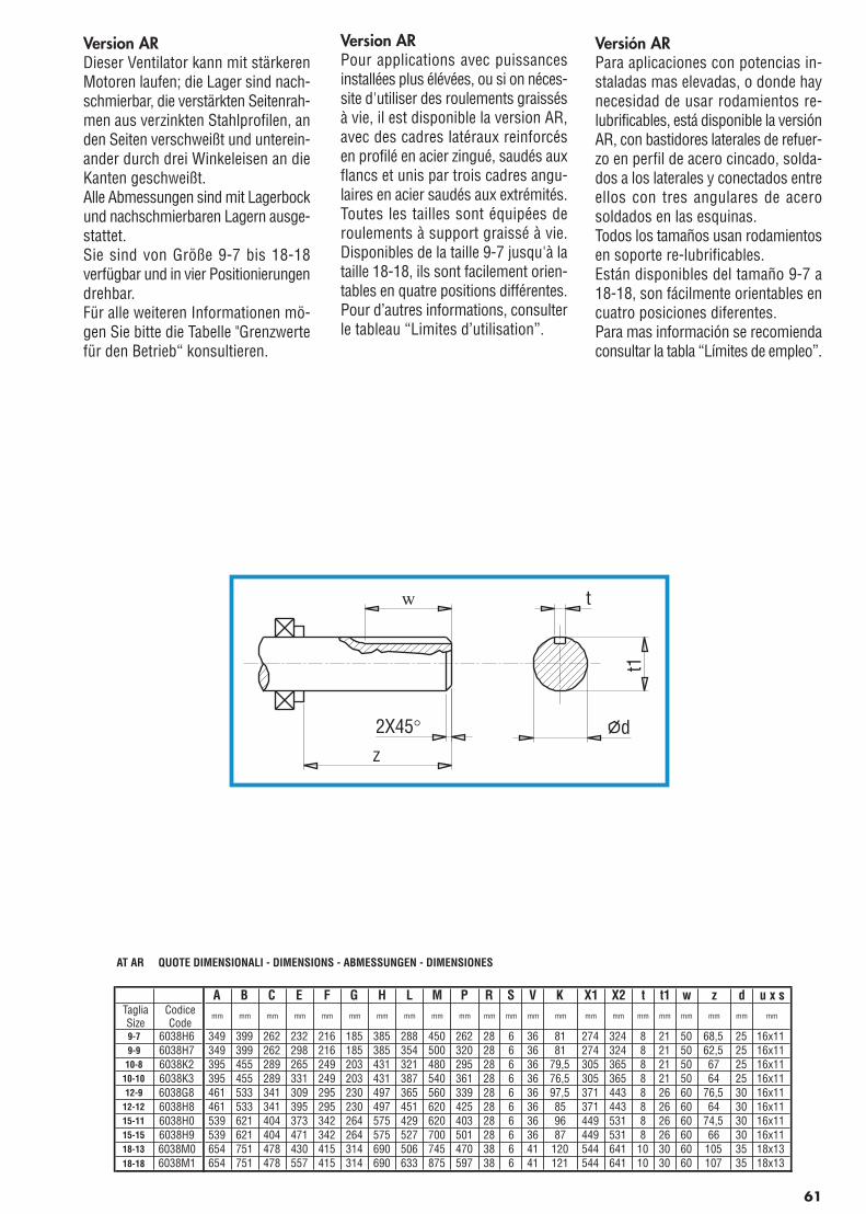
Pag.61_Cat_AT 2006 21-04-2006 10:38 Pagina 1
C M Y CM MY CY CMY K
Version ARDieser Ventilator kann mit stärkerenMotoren laufen; die Lager sind nach-schmierbar, die verstärkten Seitenrah-men aus verzinkten Stahlprofilen, anden Seiten verschweißt und unterein-ander durch drei Winkeleisen an dieKanten geschweißt.Alle Abmessungen sind mit Lagerbockund nachschmierbaren Lagern ausge-stattet.Sie sind von Größe 9-7 bis 18-18verfügbar und in vier Positionierungendrehbar.Für alle weiteren Informationen mö-gen Sie bitte die Tabelle "Grenzwertefür den Betrieb“ konsultieren.
Version ARPour applications avec puissancesinstallées plus élévées, ou si on néces-site d'utiliser des roulements graissésà vie, il est disponible la version AR,avec des cadres latéraux reinforcésen profilé en acier zingué, saudés auxflancs et unis par trois cadres angu-laires en acier saudés aux extrémités.Toutes les tailles sont équipées deroulements à support graissé à vie.Disponibles de la taille 9-7 jusqu'à lataille 18-18, ils sont facilement orien-tables en quatre positions différentes.Pour d’autres informations, consulterle tableau “Limites d’utilisation”.
Versión ARPara aplicaciones con potencias in-staladas mas elevadas, o donde haynecesidad de usar rodamientos re-lubrificables, está disponible la versiónAR, con bastidores laterales de refuer-zo en perfil de acero cincado, solda-dos a los laterales y conectados entreellos con tres angulares de acerosoldados en las esquinas.Todos los tamaños usan rodamientosen soporte re-lubrificables.Están disponibles del tamaño 9-7 a18-18, son fácilmente orientables encuatro posiciones diferentes.Para mas información se recomiendaconsultar la tabla “Límites de empleo”.
AT AR QUOTE DIMENSIONALI - DIMENSIONS - ABMESSUNGEN - DIMENSIONES
A B C E F G H L M P R S V K X1 X2 t t1 w z d u x sTagliaSize
CodiceCode
mm mm mm mm mm mm mm mm mm mm mm mm mm mm mm mm mm mm mm mm mm mm
9-7 6038H6 349 399 262 232 216 185 385 288 450 262 28 6 36 81 274 324 8 21 50 68,5 25 16x119-9 6038H7 349 399 262 298 216 185 385 354 500 320 28 6 36 81 274 324 8 21 50 62,5 25 16x11
10-8 6038K2 395 455 289 265 249 203 431 321 480 295 28 6 36 79,5 305 365 8 21 50 67 25 16x1110-10 6038K3 395 455 289 331 249 203 431 387 540 361 28 6 36 76,5 305 365 8 21 50 64 25 16x1112-9 6038G8 461 533 341 309 295 230 497 365 560 339 28 6 36 97,5 371 443 8 26 60 76,5 30 16x11
12-12 6038H8 461 533 341 395 295 230 497 451 620 425 28 6 36 85 371 443 8 26 60 64 30 16x1115-11 6038H0 539 621 404 373 342 264 575 429 620 403 28 6 36 96 449 531 8 26 60 74,5 30 16x1115-15 6038H9 539 621 404 471 342 264 575 527 700 501 28 6 36 87 449 531 8 26 60 66 30 16x1118-13 6038M0 654 751 478 430 415 314 690 506 745 470 38 6 41 120 544 641 10 30 60 105 35 18x1318-18 6038M1 654 751 478 557 415 314 690 633 875 597 38 6 41 121 544 641 10 30 60 107 35 18x13
61
w
z2X45°
t
d
t1
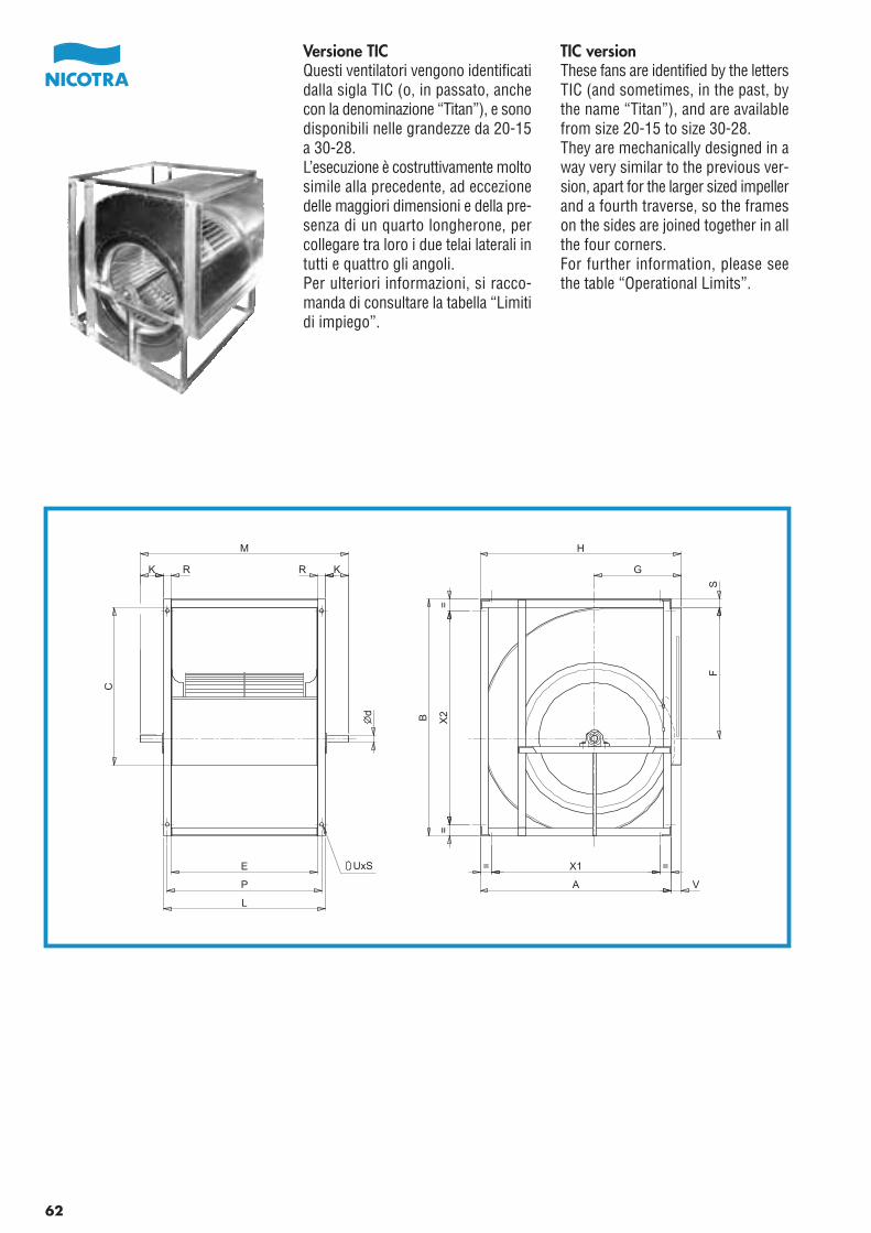
TIC versionThese fans are identified by the lettersTIC (and sometimes, in the past, bythe name “Titan”), and are availablefrom size 20-15 to size 30-28.They are mechanically designed in away very similar to the previous ver-sion, apart for the larger sized impellerand a fourth traverse, so the frameson the sides are joined together in allthe four corners.For further information, please seethe table “Operational Limits”.
Versione TICQuesti ventilatori vengono identificatidalla sigla TIC (o, in passato, anchecon la denominazione “Titan”), e sonodisponibili nelle grandezze da 20-15a 30-28.L’esecuzione è costruttivamente moltosimile alla precedente, ad eccezionedelle maggiori dimensioni e della pre-senza di un quarto longherone, percollegare tra loro i due telai laterali intutti e quattro gli angoli.Per ulteriori informazioni, si racco-manda di consultare la tabella “Limitidi impiego”.
62
E
P
K
M
K
C
X1 ==
A V
B X2
==
FS
G
H
d
UxS
RR
L
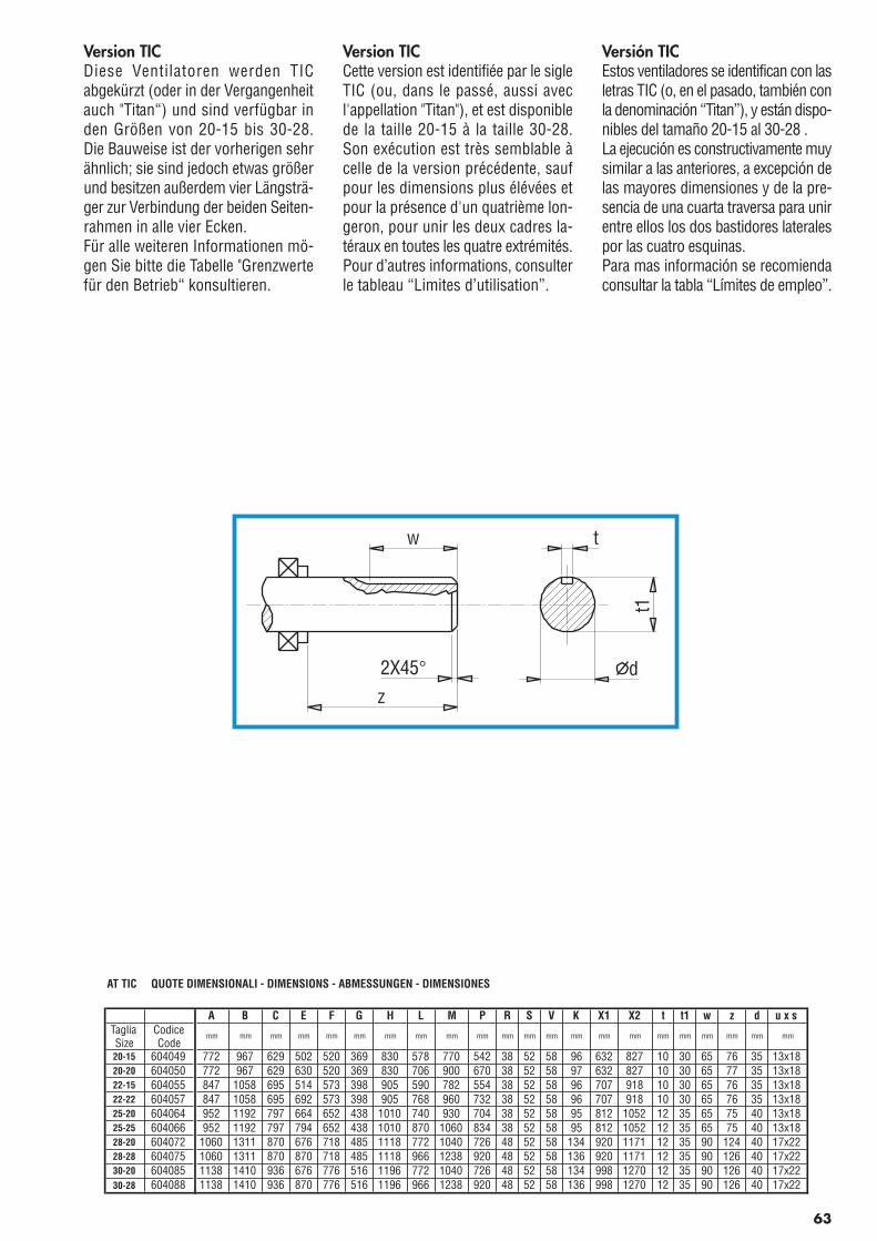
Version TICDiese Ventilatoren werden TICabgekürzt (oder in der Vergangenheitauch "Titan“) und sind verfügbar inden Größen von 20-15 bis 30-28.Die Bauweise ist der vorherigen sehrähnlich; sie sind jedoch etwas größerund besitzen außerdem vier Längsträ-ger zur Verbindung der beiden Seiten-rahmen in alle vier Ecken.Für alle weiteren Informationen mö-gen Sie bitte die Tabelle "Grenzwertefür den Betrieb“ konsultieren.
Version TICCette version est identifiée par le sigleTIC (ou, dans le passé, aussi avecl'appellation "Titan"), et est disponiblede la taille 20-15 à la taille 30-28.Son exécution est très semblable àcelle de la version précédente, saufpour les dimensions plus élévées etpour la présence d'un quatrième lon-geron, pour unir les deux cadres la-téraux en toutes les quatre extrémités.Pour d’autres informations, consulterle tableau “Limites d’utilisation”.
Versión TICEstos ventiladores se identifican con lasletras TIC (o, en el pasado, también conla denominación “Titan”), y están dispo-nibles del tamaño 20-15 al 30-28 .La ejecución es constructivamente muysimilar a las anteriores, a excepción delas mayores dimensiones y de la pre-sencia de una cuarta traversa para unirentre ellos los dos bastidores lateralespor las cuatro esquinas.Para mas información se recomiendaconsultar la tabla “Límites de empleo”.
AT TIC QUOTE DIMENSIONALI - DIMENSIONS - ABMESSUNGEN - DIMENSIONES
A B C E F G H L M P R S V K X1 X2 t t1 w z d u x sTagliaSize
CodiceCode
mm mm mm mm mm mm mm mm mm mm mm mm mm mm mm mm mm mm mm mm mm mm
20-15 604049 772 967 629 502 520 369 830 578 770 542 38 52 58 96 632 827 10 30 65 76 35 13x1820-20 604050 772 967 629 630 520 369 830 706 900 670 38 52 58 97 632 827 10 30 65 77 35 13x1822-15 604055 847 1058 695 514 573 398 905 590 782 554 38 52 58 96 707 918 10 30 65 76 35 13x1822-22 604057 847 1058 695 692 573 398 905 768 960 732 38 52 58 96 707 918 10 30 65 76 35 13x1825-20 604064 952 1192 797 664 652 438 1010 740 930 704 38 52 58 95 812 1052 12 35 65 75 40 13x1825-25 604066 952 1192 797 794 652 438 1010 870 1060 834 38 52 58 95 812 1052 12 35 65 75 40 13x1828-20 604072 1060 1311 870 676 718 485 1118 772 1040 726 48 52 58 134 920 1171 12 35 90 124 40 17x2228-28 604075 1060 1311 870 870 718 485 1118 966 1238 920 48 52 58 136 920 1171 12 35 90 126 40 17x2230-20 604085 1138 1410 936 676 776 516 1196 772 1040 726 48 52 58 134 998 1270 12 35 90 126 40 17x2230-28 604088 1138 1410 936 870 776 516 1196 966 1238 920 48 52 58 136 998 1270 12 35 90 126 40 17x22
63
w
z
2X45°
t
dt1
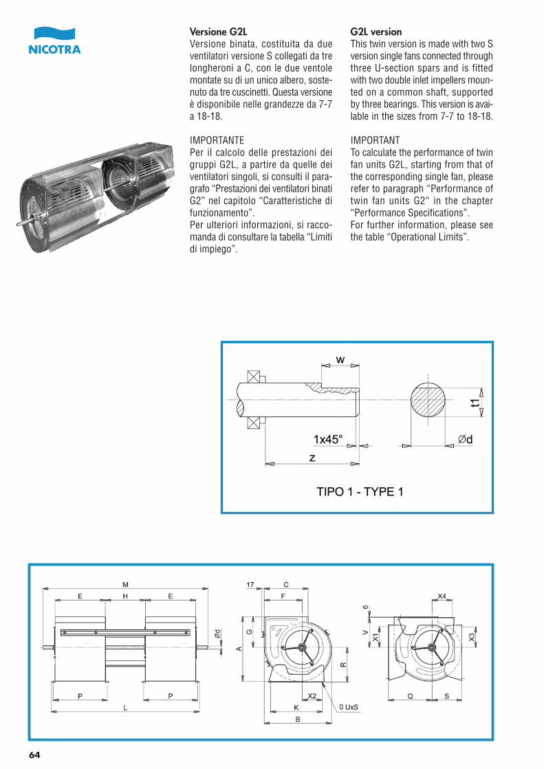
Pag.64_Cat_AT 2006 21-04-2006 10:39 Pagina 1
C M Y CM MY CY CMY K
G2L versionThis twin version is made with two Sversion single fans connected throughthree U-section spars and is fittedwith two double inlet impellers moun-ted on a common shaft, supportedby three bearings. This version is avai-lable in the sizes from 7-7 to 18-18.
IMPORTANTTo calculate the performance of twinfan units G2L, starting from that ofthe corresponding single fan, pleaserefer to paragraph “Performance oftwin fan units G2“ in the chapter“Performance Specifications”.For further information, please seethe table “Operational Limits”.
Versione G2LVersione binata, costituita da dueventilatori versione S collegati da trelongheroni a C, con le due ventolemontate su di un unico albero, soste-nuto da tre cuscinetti. Questa versioneè disponibile nelle grandezze da 7-7a 18-18.
IMPORTANTEPer il calcolo delle prestazioni deigruppi G2L, a partire da quelle deiventilatori singoli, si consulti il para-grafo “Prestazioni dei ventilatori binatiG2” nel capitolo “Caratteristiche difunzionamento”.Per ulteriori informazioni, si racco-manda di consultare la tabella “Limitidi impiego”.
64
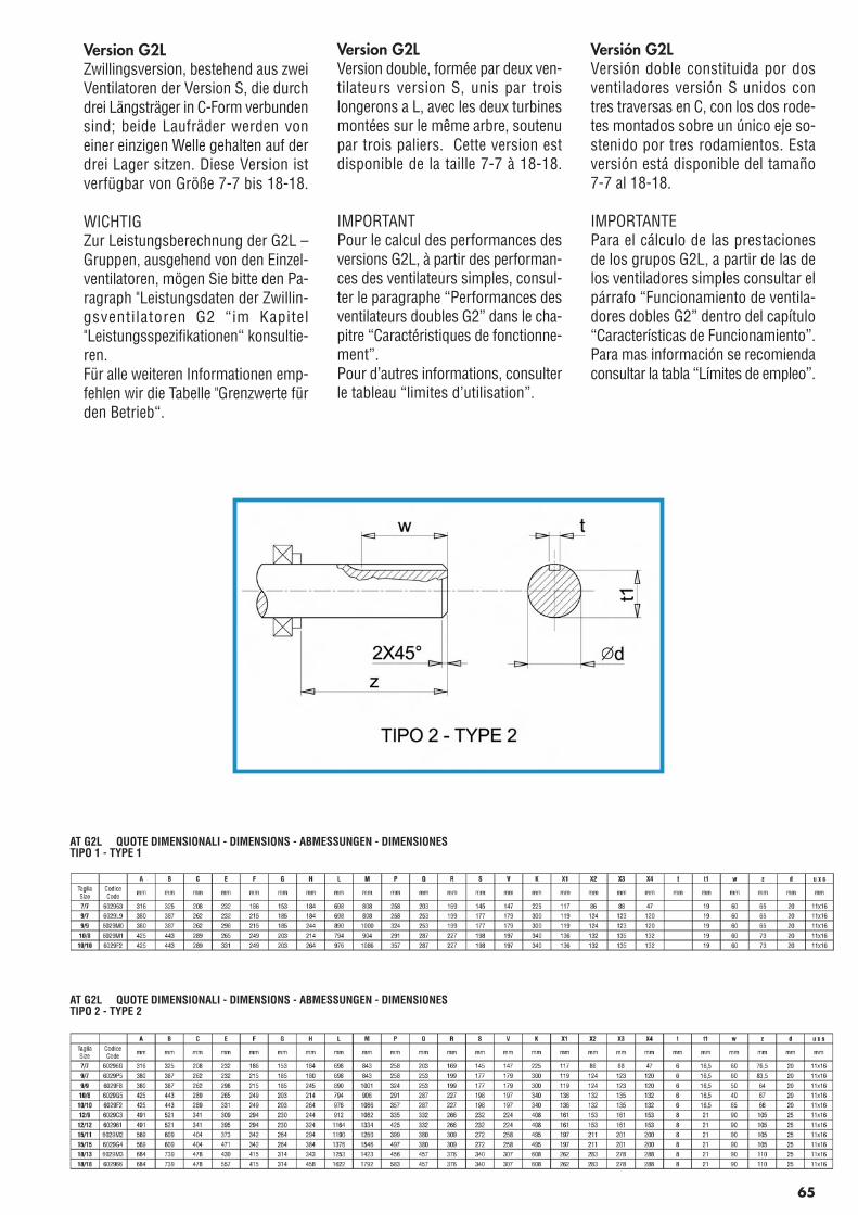
Pag.65_Cat_AT_2006.fh11 21-04-2006 10:41 Pagina 1
C M Y CM MY CY CMY K
65
Version G2LZwillingsversion, bestehend aus zweiVentilatoren der Version S, die durchdrei Längsträger in C-Form verbundensind; beide Laufräder werden voneiner einzigen Welle gehalten auf derdrei Lager sitzen. Diese Version istverfügbar von Größe 7-7 bis 18-18.
WICHTIGZur Leistungsberechnung der G2L –Gruppen, ausgehend von den Einzel-ventilatoren, mögen Sie bitte den Pa-ragraph "Leistungsdaten der Zwillin-gsventilatoren G2 “im Kapitel"Leistungsspezifikationen“ konsultie-ren.Für alle weiteren Informationen emp-fehlen wir die Tabelle "Grenzwerte fürden Betrieb“.
Version G2LVersion double, formée par deux ven-tilateurs version S, unis par troislongerons a L, avec les deux turbinesmontées sur le même arbre, soutenupar trois paliers. Cette version estdisponible de la taille 7-7 à 18-18.
IMPORTANTPour le calcul des performances desversions G2L, à partir des performan-ces des ventilateurs simples, consul-ter le paragraphe “Performances desventilateurs doubles G2” dans le cha-pitre “Caractéristiques de fonctionne-ment”.Pour d’autres informations, consulterle tableau “limites d’utilisation”.
Versión G2LVersión doble constituida por dosventiladores versión S unidos contres traversas en C, con los dos rode-tes montados sobre un único eje so-stenido por tres rodamientos. Estaversión está disponible del tamaño7-7 al 18-18.
IMPORTANTEPara el cálculo de las prestacionesde los grupos G2L, a partir de las delos ventiladores simples consultar elpárrafo “Funcionamiento de ventila-dores dobles G2” dentro del capítulo“Características de Funcionamiento”.Para mas información se recomiendaconsultar la tabla “Límites de empleo”.
AT G2L QUOTE DIMENSIONALI - DIMENSIONS - ABMESSUNGEN - DIMENSIONESTIPO 1 - TYPE 1
AT G2L QUOTE DIMENSIONALI - DIMENSIONS - ABMESSUNGEN - DIMENSIONESTIPO 2 - TYPE 2
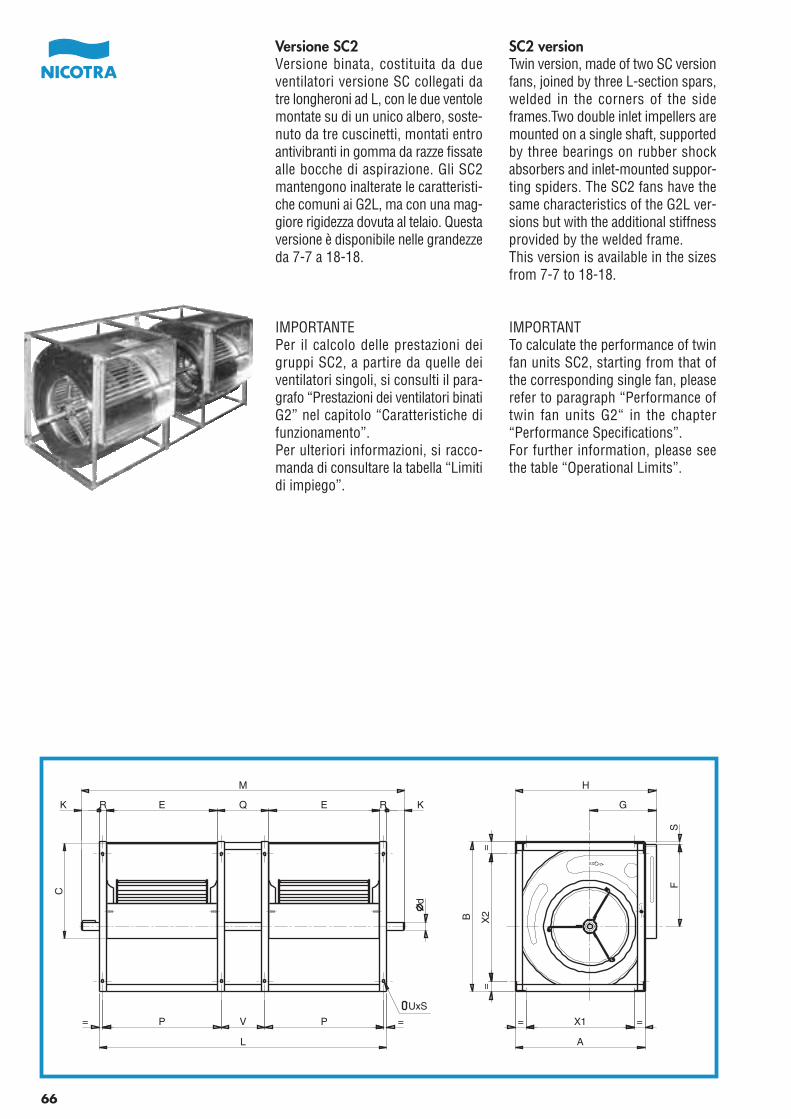
SC2 versionTwin version, made of two SC versionfans, joined by three L-section spars,welded in the corners of the sideframes.Two double inlet impellers aremounted on a single shaft, supportedby three bearings on rubber shockabsorbers and inlet-mounted suppor-ting spiders. The SC2 fans have thesame characteristics of the G2L ver-sions but with the additional stiffnessprovided by the welded frame.This version is available in the sizesfrom 7-7 to 18-18.
IMPORTANTTo calculate the performance of twinfan units SC2, starting from that ofthe corresponding single fan, pleaserefer to paragraph “Performance oftwin fan units G2“ in the chapter“Performance Specifications”.For further information, please seethe table “Operational Limits”.
Versione SC2Versione binata, costituita da dueventilatori versione SC collegati datre longheroni ad L, con le due ventolemontate su di un unico albero, soste-nuto da tre cuscinetti, montati entroantivibranti in gomma da razze fissatealle bocche di aspirazione. Gli SC2mantengono inalterate le caratteristi-che comuni ai G2L, ma con una mag-giore rigidezza dovuta al telaio. Questaversione è disponibile nelle grandezzeda 7-7 a 18-18.
IMPORTANTEPer il calcolo delle prestazioni deigruppi SC2, a partire da quelle deiventilatori singoli, si consulti il para-grafo “Prestazioni dei ventilatori binatiG2” nel capitolo “Caratteristiche difunzionamento”.Per ulteriori informazioni, si racco-manda di consultare la tabella “Limitidi impiego”.
P V P
L
d
K R R KE Q E
M
C
X1 ==
A
FS
G
H
=X
2=
B
==
UxS
66
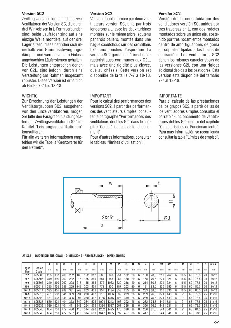
Version SC2Zwillingsversion, bestehend aus zweiVentilatoren der Version SC, die durchdrei Winkeleisen in L-Form verbundensind; beide Laufräder sind auf eineeinzige Welle montiert, auf der dreiLager sitzen; diese befinden sich in-nerhalb von Gummischwingungs-dämpfer und werden von am Einlassangebrachten Läufersternen gehalten.Die Leistungen entsprechen denenvon G2L, sind jedoch durch eineVersteifung am Rahmen insgesamtrobuster. Diese Version ist erhältlichab Größe 7-7 bis 18-18.
WICHTIGZur Errechnung der Leistungen derVentilatorgruppen SC2, ausgehendvon den Einzelventilatoren, mögenSie bitte den Paragraph "Leistungsda-ten der Zwillingsventilatoren G2“ imKapitel "Leistungsspezifikationen“konsultieren.Für alle weiteren Informationen emp-fehlen wir die Tabelle "Grenzwerte fürden Betrieb“.
Version SC2Version double, formée par deux ven-tilateurs version SC, unis par troislongerons a L, avec les deux turbinesmontées sur le même arbre, soutenupar trois paliers, montés dans unebague caoutchouc sur des croisillonsfixés aux bouches d'aspiration. Laversion SC2 garde inaltérées les ca-racteristiques communes aux G2L,mais avec une rigidité plus élévée,due au châssis. Cette version estdisponible de la taille 7-7 à 18-18.
IMPORTANTPour le calcul des performances desversions SC2, à partir des performan-ces des ventilateurs simples, consul-ter le paragraphe “Performances desventilateurs doubles G2” dans le cha-pitre “Caractéristiques de fonctionne-ment”.Pour d’autres informations, consulterle tableau “limites d’utilisation”.
Versión SC2Versión doble, constituida por dosventiladores versión SC, unidos portres traversas en L, con dos rodetesmontados sobre un único eje, soste-nido por tres rodamientos montadosdentro de amortiguadores de gomaen soportes fijadas a las bocas deaspiración. Los ventiladores SC2tienen los mismos características delas versiones G2L con una rigidezadicional debida a los bastidores. Estaversión esta disponible del tamaño7-7 al 18-18.
IMPORTANTEPara el cálculo de las prestacionesde los grupos SC2, a partir de las delos ventiladores simples consultar elpárrafo “Funcionamiento de ventila-dores dobles G2” dentro del capítulo“Características de Funcionamiento”.Para mas información se recomiendaconsultar la tabla “Límites de empleo”.
AT SC2 QUOTE DIMENSIONALI - DIMENSIONS - ABMESSUNGEN - DIMENSIONES
A B C E F G H L M P Q R S V K X1 X2 t t1 w z d u x sTagliaSize
CodiceCode
mm 60 mm mm mm mm mm mm mm mm mm mm mm mm mm mm mm mm mm mm mm mm mm
7-7 605503 285 337 208 232 186 152 317 686 843 254 182 20 6 160 78,5 210 262 6 16,5 60 75,5 20 9x129-7 605506 349 399 262 232 215 185 385 684 843 254 180 20 6 158 79,5 274 324 6 16,5 60 76,5 20 9x129-9 605508 349 399 262 298 215 185 385 872 1033 320 236 20 6 214 80,5 274 324 6 16,5 60 77,5 20 9x12
10-8 605512 395 455 289 265 249 203 431 773 950 287 203 20 6 181 88,5 330 390 6 16,5 60 85,5 20 9x1210-10 605514 395 455 289 331 249 203 431 957 1134 353 255 20 6 233 88,5 330 390 6 16,5 60 85,5 20 9x1212-9 605518 461 533 341 309 294 230 497 913 1066 339 239 28 6 209 76,5 371 443 8 21 65 79,5 25 11x16
12-12 605520 461 533 341 395 294 230 497 1165 1316 425 319 28 6 289 75,5 371 443 8 21 65 78,5 25 11x1615-11 605535 539 621 404 373 342 264 575 1094 1243 403 292 28 6 262 74,5 449 531 8 21 65 77,5 25 11x1615-15 605538 539 621 404 471 342 264 575 1384 1537 501 386 28 6 356 76,5 449 531 8 21 65 79,5 25 11x1618-13 605546 654 751 477 430 415 314 690 1262 1425 470 326 38 6 286 81,5 544 641 8 21 65 84,5 25 11x1618-18 605548 654 751 477 557 415 314 690 1647 1805 597 457 38 6 417 79 544 641 8 21 65 82 25 11x16
67
w
z
2X45°
t
d
t1
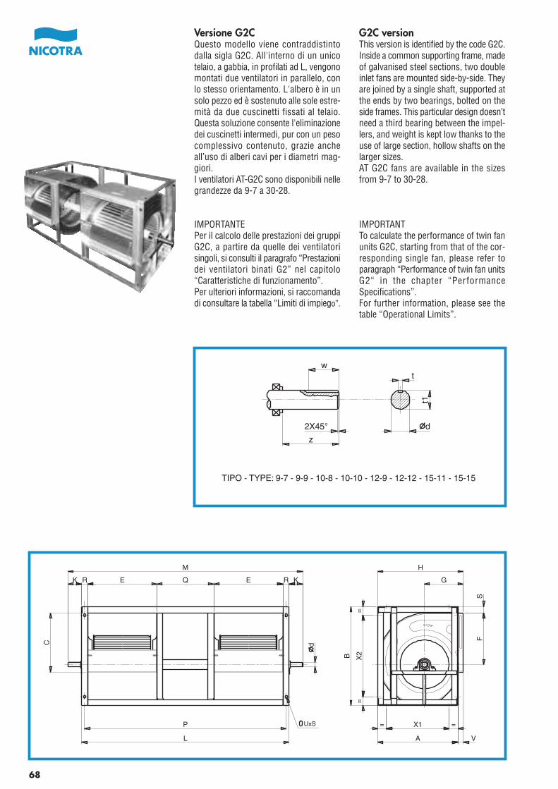
G2C versionThis version is identified by the code G2C.Inside a common supporting frame, madeof galvanised steel sections, two doubleinlet fans are mounted side-by-side. Theyare joined by a single shaft, supported atthe ends by two bearings, bolted on theside frames. This particular design doesn’tneed a third bearing between the impel-lers, and weight is kept low thanks to theuse of large section, hollow shafts on thelarger sizes.AT G2C fans are available in the sizesfrom 9-7 to 30-28.
IMPORTANTTo calculate the performance of twin fanunits G2C, starting from that of the cor-responding single fan, please refer toparagraph “Performance of twin fan unitsG2“ in the chapter “PerformanceSpecifications”.For further information, please see thetable “Operational Limits”.
Versione G2CQuesto modello viene contraddistintodalla sigla G2C. All'interno di un unicotelaio, a gabbia, in profilati ad L, vengonomontati due ventilatori in parallelo, conlo stesso orientamento. L'albero è in unsolo pezzo ed è sostenuto alle sole estre-mità da due cuscinetti fissati al telaio.Questa soluzione consente l'eliminazionedei cuscinetti intermedi, pur con un pesocomplessivo contenuto, grazie ancheall’uso di alberi cavi per i diametri mag-giori.I ventilatori AT-G2C sono disponibili nellegrandezze da 9-7 a 30-28.
IMPORTANTEPer il calcolo delle prestazioni dei gruppiG2C, a partire da quelle dei ventilatorisingoli, si consulti il paragrafo “Prestazionidei ventilatori binati G2” nel capitolo“Caratteristiche di funzionamento”.Per ulteriori informazioni, si raccomandadi consultare la tabella “Limiti di impiego”.
L
C
RK E Q E R K
d
X1= =
A V
B
==
X2
SF
G
H
P UxS
M
w
z
2X45°
t
t1
TIPO - TYPE: 9-7 - 9-9 - 10-8 - 10-10 - 12-9 - 12-12 - 15-11 - 15-15
d
68
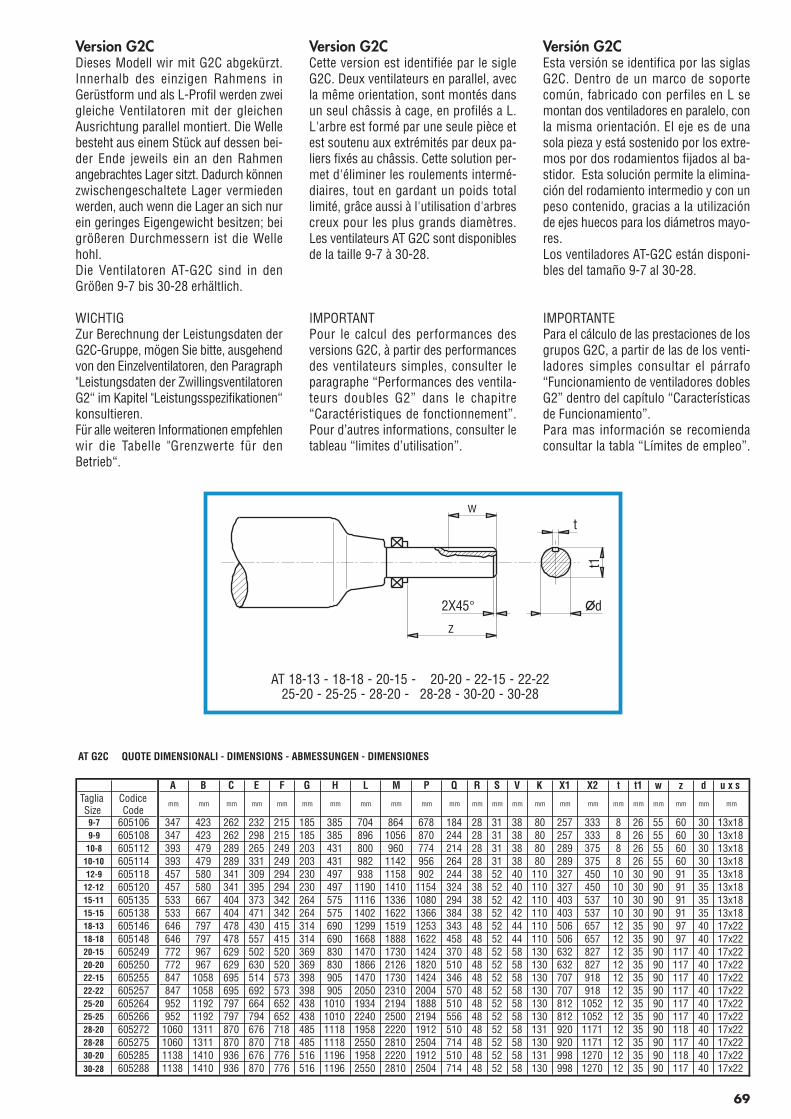
Version G2CDieses Modell wir mit G2C abgekürzt.Innerhalb des einzigen Rahmens inGerüstform und als L-Profil werden zweigleiche Ventilatoren mit der gleichenAusrichtung parallel montiert. Die Wellebesteht aus einem Stück auf dessen bei-der Ende jeweils ein an den Rahmenangebrachtes Lager sitzt. Dadurch könnenzwischengeschaltete Lager vermiedenwerden, auch wenn die Lager an sich nurein geringes Eigengewicht besitzen; beigrößeren Durchmessern ist die Wellehohl.Die Ventilatoren AT-G2C sind in denGrößen 9-7 bis 30-28 erhältlich.
WICHTIGZur Berechnung der Leistungsdaten derG2C-Gruppe, mögen Sie bitte, ausgehendvon den Einzelventilatoren, den Paragraph"Leistungsdaten der ZwillingsventilatorenG2“ im Kapitel "Leistungsspezifikationen“konsultieren.Für alle weiteren Informationen empfehlenwir die Tabelle "Grenzwerte für denBetrieb“.
Version G2CCette version est identifiée par le sigleG2C. Deux ventilateurs en parallel, avecla même orientation, sont montés dansun seul châssis à cage, en profilés a L.L'arbre est formé par une seule pièce etest soutenu aux extrémités par deux pa-liers fixés au châssis. Cette solution per-met d'éliminer les roulements intermé-diaires, tout en gardant un poids totallimité, grâce aussi à l'utilisation d'arbrescreux pour les plus grands diamètres.Les ventilateurs AT G2C sont disponiblesde la taille 9-7 à 30-28.
IMPORTANTPour le calcul des performances desversions G2C, à partir des performancesdes ventilateurs simples, consulter leparagraphe “Performances des ventila-teurs doubles G2” dans le chapitre“Caractéristiques de fonctionnement”.Pour d’autres informations, consulter letableau “limites d’utilisation”.
Versión G2CEsta versión se identifica por las siglasG2C. Dentro de un marco de soportecomún, fabricado con perfiles en L semontan dos ventiladores en paralelo, conla misma orientación. El eje es de unasola pieza y está sostenido por los extre-mos por dos rodamientos fijados al ba-stidor. Esta solución permite la elimina-ción del rodamiento intermedio y con unpeso contenido, gracias a la utilizaciónde ejes huecos para los diámetros mayo-res.Los ventiladores AT-G2C están disponi-bles del tamaño 9-7 al 30-28.
IMPORTANTEPara el cálculo de las prestaciones de losgrupos G2C, a partir de las de los venti-ladores simples consultar el párrafo“Funcionamiento de ventiladores doblesG2” dentro del capítulo “Característicasde Funcionamiento”.Para mas información se recomiendaconsultar la tabla “Límites de empleo”.
AT G2C QUOTE DIMENSIONALI - DIMENSIONS - ABMESSUNGEN - DIMENSIONES
A B C E F G H L M P Q R S V K X1 X2 t t1 w z d u x sTagliaSize
CodiceCode
mm mm mm mm mm mm mm mm mm mm mm mm mm mm mm mm mm mm mm mm mm mm mm
9-7 605106 347 423 262 232 215 185 385 704 864 678 184 28 31 38 80 257 333 8 26 55 60 30 13x189-9 605108 347 423 262 298 215 185 385 896 1056 870 244 28 31 38 80 257 333 8 26 55 60 30 13x18
10-8 605112 393 479 289 265 249 203 431 800 960 774 214 28 31 38 80 289 375 8 26 55 60 30 13x1810-10 605114 393 479 289 331 249 203 431 982 1142 956 264 28 31 38 80 289 375 8 26 55 60 30 13x1812-9 605118 457 580 341 309 294 230 497 938 1158 902 244 38 52 40 110 327 450 10 30 90 91 35 13x18
12-12 605120 457 580 341 395 294 230 497 1190 1410 1154 324 38 52 40 110 327 450 10 30 90 91 35 13x1815-11 605135 533 667 404 373 342 264 575 1116 1336 1080 294 38 52 42 110 403 537 10 30 90 91 35 13x1815-15 605138 533 667 404 471 342 264 575 1402 1622 1366 384 38 52 42 110 403 537 10 30 90 91 35 13x1818-13 605146 646 797 478 430 415 314 690 1299 1519 1253 343 48 52 44 110 506 657 12 35 90 97 40 17x2218-18 605148 646 797 478 557 415 314 690 1668 1888 1622 458 48 52 44 110 506 657 12 35 90 97 40 17x2220-15 605249 772 967 629 502 520 369 830 1470 1730 1424 370 48 52 58 130 632 827 12 35 90 117 40 17x2220-20 605250 772 967 629 630 520 369 830 1866 2126 1820 510 48 52 58 130 632 827 12 35 90 117 40 17x2222-15 605255 847 1058 695 514 573 398 905 1470 1730 1424 346 48 52 58 130 707 918 12 35 90 117 40 17x2222-22 605257 847 1058 695 692 573 398 905 2050 2310 2004 570 48 52 58 130 707 918 12 35 90 117 40 17x2225-20 605264 952 1192 797 664 652 438 1010 1934 2194 1888 510 48 52 58 130 812 1052 12 35 90 117 40 17x2225-25 605266 952 1192 797 794 652 438 1010 2240 2500 2194 556 48 52 58 130 812 1052 12 35 90 117 40 17x2228-20 605272 1060 1311 870 676 718 485 1118 1958 2220 1912 510 48 52 58 131 920 1171 12 35 90 118 40 17x2228-28 605275 1060 1311 870 870 718 485 1118 2550 2810 2504 714 48 52 58 130 920 1171 12 35 90 117 40 17x2230-20 605285 1138 1410 936 676 776 516 1196 1958 2220 1912 510 48 52 58 131 998 1270 12 35 90 118 40 17x2230-28 605288 1138 1410 936 870 776 516 1196 2550 2810 2504 714 48 52 58 130 998 1270 12 35 90 117 40 17x22
w
z
2X45°
t
dt1
AT 18-13 - 18-18 - 20-15 - 20-20 - 22-15 - 22-2225-20 - 25-25 - 28-20 - 28-28 - 30-20 - 30-28
69
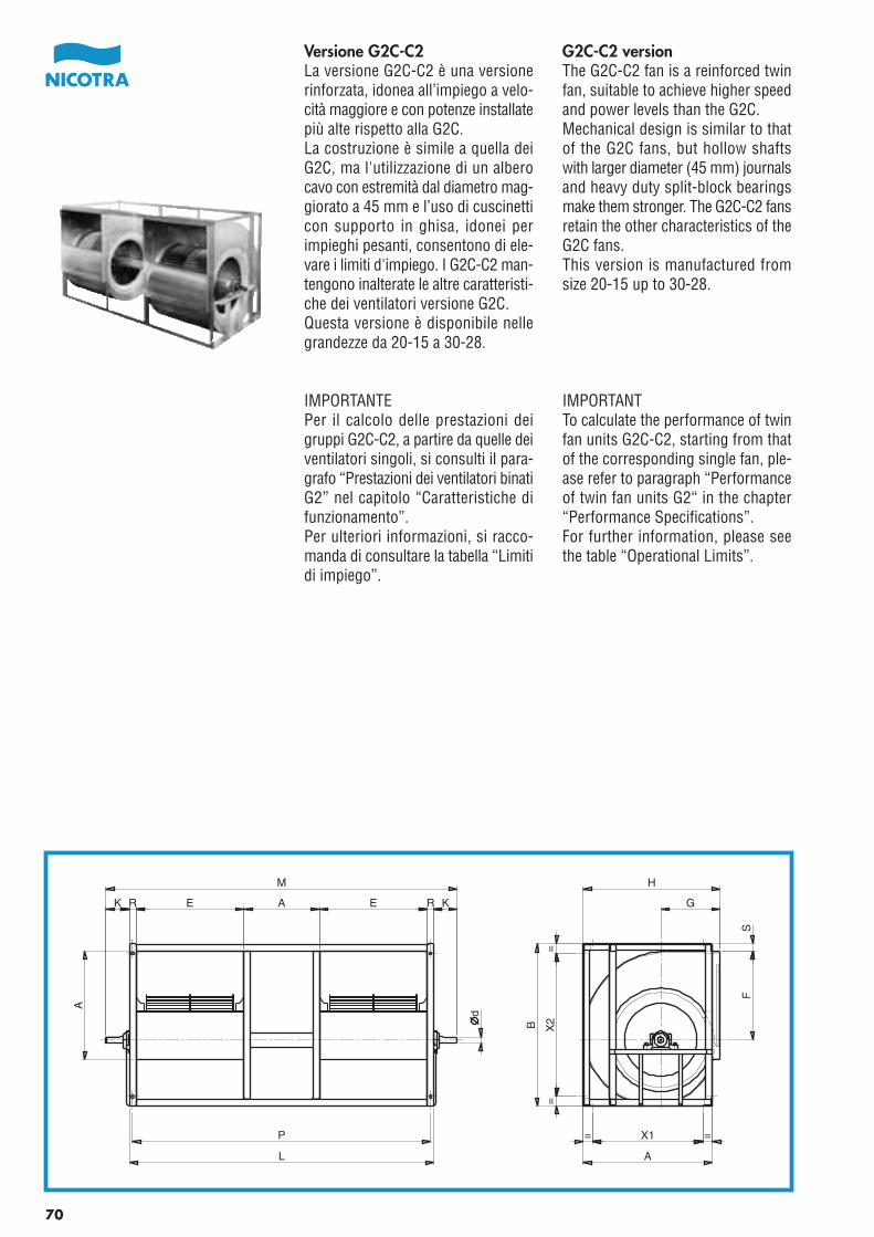
G2C-C2 versionThe G2C-C2 fan is a reinforced twinfan, suitable to achieve higher speedand power levels than the G2C.Mechanical design is similar to thatof the G2C fans, but hollow shaftswith larger diameter (45 mm) journalsand heavy duty split-block bearingsmake them stronger. The G2C-C2 fansretain the other characteristics of theG2C fans.This version is manufactured fromsize 20-15 up to 30-28.
IMPORTANTTo calculate the performance of twinfan units G2C-C2, starting from thatof the corresponding single fan, ple-ase refer to paragraph “Performanceof twin fan units G2“ in the chapter“Performance Specifications”.For further information, please seethe table “Operational Limits”.
Versione G2C-C2La versione G2C-C2 è una versionerinforzata, idonea all’impiego a velo-cità maggiore e con potenze installatepiù alte rispetto alla G2C.La costruzione è simile a quella deiG2C, ma l'utilizzazione di un alberocavo con estremità dal diametro mag-giorato a 45 mm e l’uso di cuscinetticon supporto in ghisa, idonei perimpieghi pesanti, consentono di ele-vare i limiti d'impiego. I G2C-C2 man-tengono inalterate le altre caratteristi-che dei ventilatori versione G2C.Questa versione è disponibile nellegrandezze da 20-15 a 30-28.
IMPORTANTEPer il calcolo delle prestazioni deigruppi G2C-C2, a partire da quelle deiventilatori singoli, si consulti il para-grafo “Prestazioni dei ventilatori binatiG2” nel capitolo “Caratteristiche difunzionamento”.Per ulteriori informazioni, si racco-manda di consultare la tabella “Limitidi impiego”.
P
L
A
d
R E A E RK K
M
X1 ==
A
=
B X2
=
SF
G
H
70
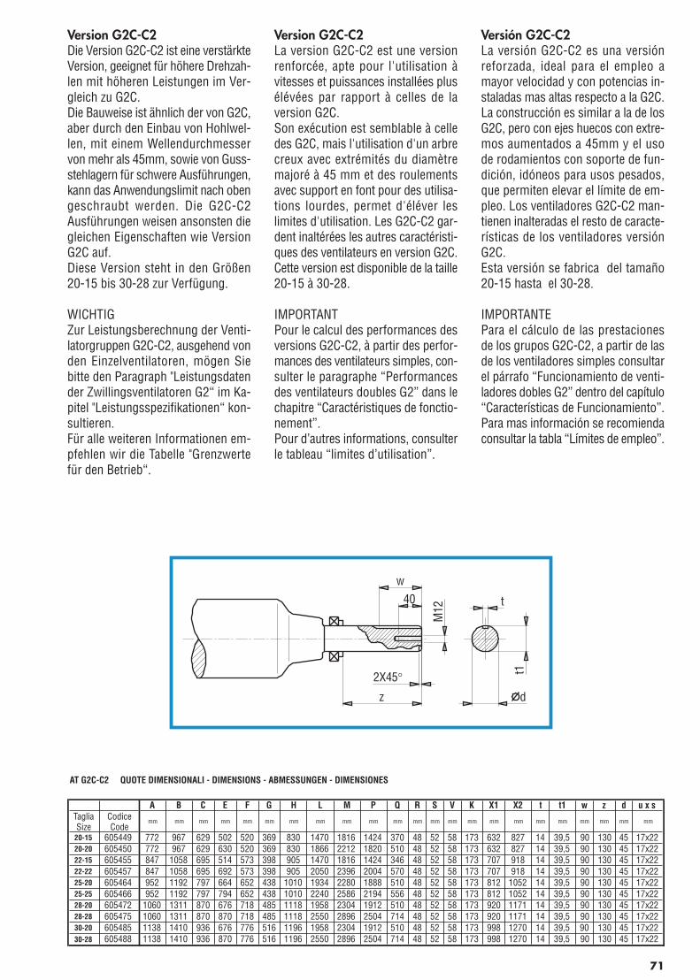
Pag.71_Cat_AT 2006 21-04-2006 10:43 Pagina 1
C M Y CM MY CY CMY K
Version G2C-C2Die Version G2C-C2 ist eine verstärkteVersion, geeignet für höhere Drehzah-len mit höheren Leistungen im Ver-gleich zu G2C.Die Bauweise ist ähnlich der von G2C,aber durch den Einbau von Hohlwel-len, mit einem Wellendurchmesservon mehr als 45mm, sowie von Guss-stehlagern für schwere Ausführungen,kann das Anwendungslimit nach obengeschraubt werden. Die G2C-C2Ausführungen weisen ansonsten diegleichen Eigenschaften wie VersionG2C auf.Diese Version steht in den Größen20-15 bis 30-28 zur Verfügung.
WICHTIGZur Leistungsberechnung der Venti-latorgruppen G2C-C2, ausgehend vonden Einzelventilatoren, mögen Siebitte den Paragraph "Leistungsdatender Zwillingsventilatoren G2“ im Ka-pitel "Leistungsspezifikationen“ kon-sultieren.Für alle weiteren Informationen em-pfehlen wir die Tabelle "Grenzwertefür den Betrieb“.
Version G2C-C2La version G2C-C2 est une versionrenforcée, apte pour l'utilisation àvitesses et puissances installées plusélévées par rapport à celles de laversion G2C.Son exécution est semblable à celledes G2C, mais l'utilisation d'un arbrecreux avec extrémités du diamètremajoré à 45 mm et des roulementsavec support en font pour des utilisa-tions lourdes, permet d'éléver leslimites d'utilisation. Les G2C-C2 gar-dent inaltérées les autres caractéristi-ques des ventilateurs en version G2C.Cette version est disponible de la taille20-15 à 30-28.
IMPORTANTPour le calcul des performances desversions G2C-C2, à partir des perfor-mances des ventilateurs simples, con-sulter le paragraphe “Performancesdes ventilateurs doubles G2” dans lechapitre “Caractéristiques de fonctio-nement”.Pour d’autres informations, consulterle tableau “limites d’utilisation”.
Versión G2C-C2La versión G2C-C2 es una versiónreforzada, ideal para el empleo amayor velocidad y con potencias in-staladas mas altas respecto a la G2C.La construcción es similar a la de losG2C, pero con ejes huecos con extre-mos aumentados a 45mm y el usode rodamientos con soporte de fun-dición, idóneos para usos pesados,que permiten elevar el límite de em-pleo. Los ventiladores G2C-C2 man-tienen inalteradas el resto de caracte-rísticas de los ventiladores versiónG2C.Esta versión se fabrica del tamaño20-15 hasta el 30-28.
IMPORTANTEPara el cálculo de las prestacionesde los grupos G2C-C2, a partir de lasde los ventiladores simples consultarel párrafo “Funcionamiento de venti-ladores dobles G2” dentro del capítulo“Características de Funcionamiento”.Para mas información se recomiendaconsultar la tabla “Límites de empleo”.
AT G2C-C2 QUOTE DIMENSIONALI - DIMENSIONS - ABMESSUNGEN - DIMENSIONES
A B C E F G H L M P Q R S V K X1 X2 t t1 w z d u x sTagliaSize
CodiceCode
mm mm mm mm mm mm mm mm mm mm mm mm mm mm mm mm mm mm mm mm mm mm mm
20-15 605449 772 967 629 502 520 369 830 1470 1816 1424 370 48 52 58 173 632 827 14 39,5 90 130 45 17x2220-20 605450 772 967 629 630 520 369 830 1866 2212 1820 510 48 52 58 173 632 827 14 39,5 90 130 45 17x2222-15 605455 847 1058 695 514 573 398 905 1470 1816 1424 346 48 52 58 173 707 918 14 39,5 90 130 45 17x2222-22 605457 847 1058 695 692 573 398 905 2050 2396 2004 570 48 52 58 173 707 918 14 39,5 90 130 45 17x2225-20 605464 952 1192 797 664 652 438 1010 1934 2280 1888 510 48 52 58 173 812 1052 14 39,5 90 130 45 17x2225-25 605466 952 1192 797 794 652 438 1010 2240 2586 2194 556 48 52 58 173 812 1052 14 39,5 90 130 45 17x2228-20 605472 1060 1311 870 676 718 485 1118 1958 2304 1912 510 48 52 58 173 920 1171 14 39,5 90 130 45 17x2228-28 605475 1060 1311 870 870 718 485 1118 2550 2896 2504 714 48 52 58 173 920 1171 14 39,5 90 130 45 17x2230-20 605485 1138 1410 936 676 776 516 1196 1958 2304 1912 510 48 52 58 173 998 1270 14 39,5 90 130 45 17x2230-28 605488 1138 1410 936 870 776 516 1196 2550 2896 2504 714 48 52 58 173 998 1270 14 39,5 90 130 45 17x22
71
w
z
2X45°
t
d
t1
M12
40
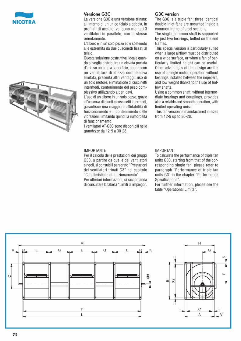
G3C versionThe G3C is a triple fan: three identicaldouble-inlet fans are mounted inside acommon frame of steel sections.The single, common shaft is supportedby just two bearings, bolted on the endframes.This special version is particularly suitedwhen a large airflow must be distributedon a wide surface, or when a fan of par-ticularly limited height can be useful.Other advantages of this design are theuse of a single motor, operation withoutbearings installed between the impellers,and low weight thanks to the use of hol-low shafts.Using a common shaft, without interme-diate bearings and couplings, providesalso a reliable and smooth operation, withlimited operating noise.This fan version is manufactured in sizesfrom 12-9 up to 30-28.
IMPORTANTTo calculate the performance of triple fanunits G3C, starting from that of the cor-responding single fan, please refer toparagraph “Performance of triple fanunits G3“ in the chapter “PerformanceSpecifications”.For further information, please see thetable “Operational Limits”.
Versione G3CLa versione G3C è una versione trinata:all'interno di un unico telaio a gabbia, inprofilati di acciaio, vengono montati 3ventilatori in parallelo, con lo stessoorientamento.L'albero è in un solo pezzo ed è sostenutoalle estremità da due cuscinetti fissati altelaio.Questa soluzione costruttiva, ideale quan-do si voglia distribuire un'elevata portatad'aria su un'ampia superficie, oppure conun ventilatore di altezza complessivalimitata, presenta altri vantaggi: uso diun solo motore, eliminazione di cuscinettiintermedi, contenimento del peso com-plessivo utilizzando alberi cavi.L'uso di un albero in un solo pezzo, grazieall’assenza di giunti e cuscinetti intermedi,garantisce una maggiore affidabilità difunzionamento e il contenimento dellevibrazioni, limitando quindi la rumorositàdi funzionamento.I ventilatori AT-G3C sono disponibili nellegrandezze da 12-9 a 30-28.
IMPORTANTEPer il calcolo delle prestazioni dei gruppiG3C, a partire da quelle dei ventilatorisingoli, si consulti il paragrafo “Prestazionidei ventilatori trinati G3” nel capitolo“Caratteristiche di funzionamento”.Per ulteriori informazioni, si raccomandadi consultare la tabella “Limiti di impiego”.
P
L
dC
K R E Q E Q E R K
M
X1=
=
=
X2
=
B
H
G
FS
A V
72
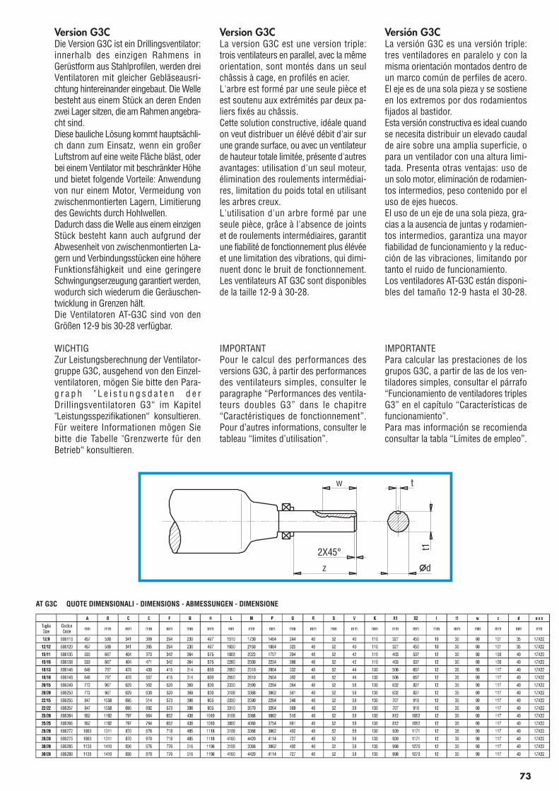
Pag.73_Cat_AT_2006 21-04-2006 10:12 Pagina 1
C M Y CM MY CY CMY K
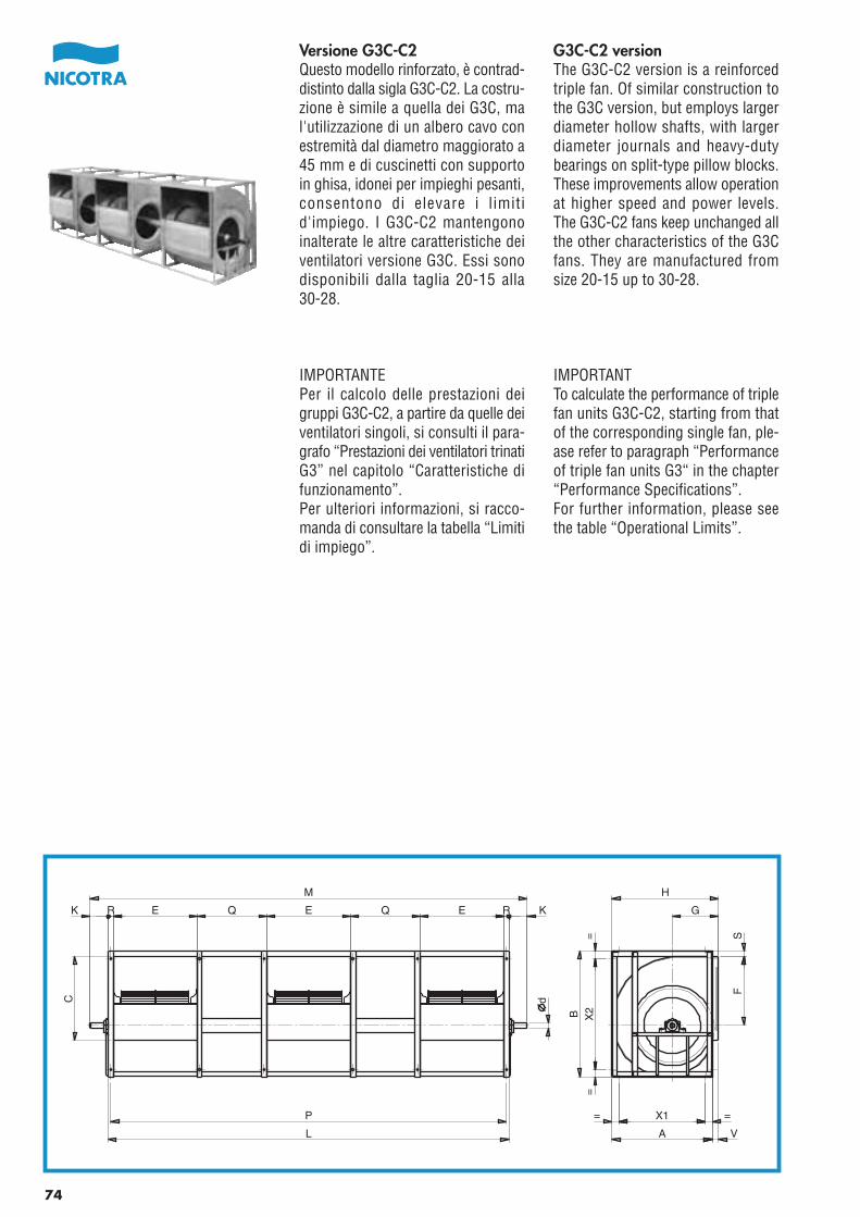
G3C-C2 versionThe G3C-C2 version is a reinforcedtriple fan. Of similar construction tothe G3C version, but employs largerdiameter hollow shafts, with largerdiameter journals and heavy-dutybearings on split-type pillow blocks.These improvements allow operationat higher speed and power levels.The G3C-C2 fans keep unchanged allthe other characteristics of the G3Cfans. They are manufactured fromsize 20-15 up to 30-28.
IMPORTANTTo calculate the performance of triplefan units G3C-C2, starting from thatof the corresponding single fan, ple-ase refer to paragraph “Performanceof triple fan units G3“ in the chapter“Performance Specifications”.For further information, please seethe table “Operational Limits”.
Versione G3C-C2Questo modello rinforzato, è contrad-distinto dalla sigla G3C-C2. La costru-zione è simile a quella dei G3C, mal'utilizzazione di un albero cavo conestremità dal diametro maggiorato a45 mm e di cuscinetti con supportoin ghisa, idonei per impieghi pesanti,consentono di elevare i limitid'impiego. I G3C-C2 mantengonoinalterate le altre caratteristiche deiventilatori versione G3C. Essi sonodisponibili dalla taglia 20-15 alla30-28.
IMPORTANTEPer il calcolo delle prestazioni deigruppi G3C-C2, a partire da quelle deiventilatori singoli, si consulti il para-grafo “Prestazioni dei ventilatori trinatiG3” nel capitolo “Caratteristiche difunzionamento”.Per ulteriori informazioni, si racco-manda di consultare la tabella “Limitidi impiego”.
P
L
dC
R E QK E Q E R K
M
= X1 =
A V
=B
=X
2
G
H
FS
74
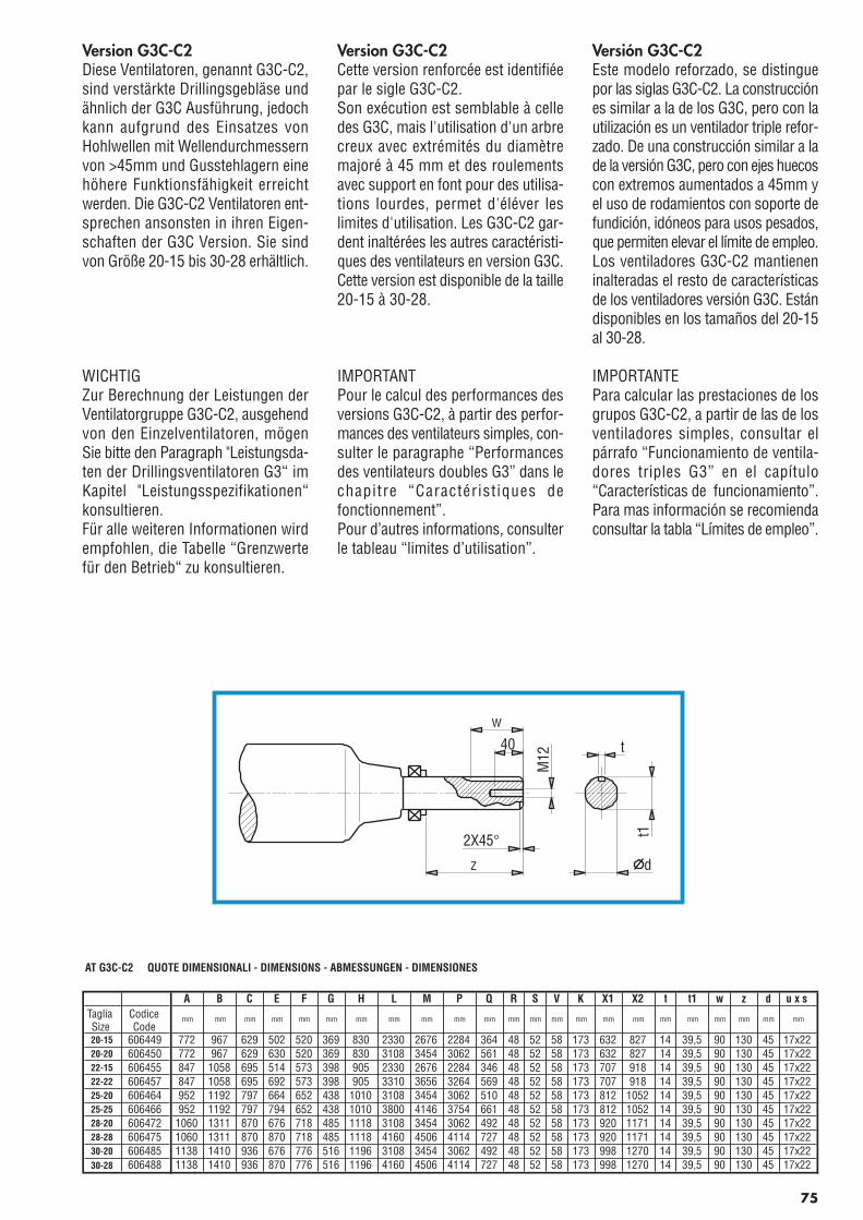
Version G3C-C2Diese Ventilatoren, genannt G3C-C2,sind verstärkte Drillingsgebläse undähnlich der G3C Ausführung, jedochkann aufgrund des Einsatzes vonHohlwellen mit Wellendurchmessernvon >45mm und Gusstehlagern einehöhere Funktionsfähigkeit erreichtwerden. Die G3C-C2 Ventilatoren ent-sprechen ansonsten in ihren Eigen-schaften der G3C Version. Sie sindvon Größe 20-15 bis 30-28 erhältlich.
WICHTIGZur Berechnung der Leistungen derVentilatorgruppe G3C-C2, ausgehendvon den Einzelventilatoren, mögenSie bitte den Paragraph "Leistungsda-ten der Drillingsventilatoren G3“ imKapitel "Leistungsspezifikationen“konsultieren.Für alle weiteren Informationen wirdempfohlen, die Tabelle “Grenzwertefür den Betrieb“ zu konsultieren.
Version G3C-C2Cette version renforcée est identifiéepar le sigle G3C-C2.Son exécution est semblable à celledes G3C, mais l'utilisation d'un arbrecreux avec extrémités du diamètremajoré à 45 mm et des roulementsavec support en font pour des utilisa-tions lourdes, permet d'éléver leslimites d'utilisation. Les G3C-C2 gar-dent inaltérées les autres caractéristi-ques des ventilateurs en version G3C.Cette version est disponible de la taille20-15 à 30-28.
IMPORTANTPour le calcul des performances desversions G3C-C2, à partir des perfor-mances des ventilateurs simples, con-sulter le paragraphe “Performancesdes ventilateurs doubles G3” dans lechapitre “Caractéristiques defonctionnement”.Pour d’autres informations, consulterle tableau “limites d’utilisation”.
Versión G3C-C2Este modelo reforzado, se distinguepor las siglas G3C-C2. La construcciónes similar a la de los G3C, pero con lautilización es un ventilador triple refor-zado. De una construcción similar a lade la versión G3C, pero con ejes huecoscon extremos aumentados a 45mm yel uso de rodamientos con soporte defundición, idóneos para usos pesados,que permiten elevar el límite de empleo.Los ventiladores G3C-C2 mantieneninalteradas el resto de característicasde los ventiladores versión G3C. Estándisponibles en los tamaños del 20-15al 30-28.
IMPORTANTEPara calcular las prestaciones de losgrupos G3C-C2, a partir de las de losventiladores simples, consultar elpárrafo “Funcionamiento de ventila-dores triples G3” en el capítulo“Características de funcionamiento”.Para mas información se recomiendaconsultar la tabla “Límites de empleo”.
AT G3C-C2 QUOTE DIMENSIONALI - DIMENSIONS - ABMESSUNGEN - DIMENSIONES
A B C E F G H L M P Q R S V K X1 X2 t t1 w z d u x sTagliaSize
CodiceCode
mm mm mm mm mm mm mm mm mm mm mm mm mm mm mm mm mm mm mm mm mm mm mm
20-15 606449 772 967 629 502 520 369 830 2330 2676 2284 364 48 52 58 173 632 827 14 39,5 90 130 45 17x2220-20 606450 772 967 629 630 520 369 830 3108 3454 3062 561 48 52 58 173 632 827 14 39,5 90 130 45 17x2222-15 606455 847 1058 695 514 573 398 905 2330 2676 2284 346 48 52 58 173 707 918 14 39,5 90 130 45 17x2222-22 606457 847 1058 695 692 573 398 905 3310 3656 3264 569 48 52 58 173 707 918 14 39,5 90 130 45 17x2225-20 606464 952 1192 797 664 652 438 1010 3108 3454 3062 510 48 52 58 173 812 1052 14 39,5 90 130 45 17x2225-25 606466 952 1192 797 794 652 438 1010 3800 4146 3754 661 48 52 58 173 812 1052 14 39,5 90 130 45 17x2228-20 606472 1060 1311 870 676 718 485 1118 3108 3454 3062 492 48 52 58 173 920 1171 14 39,5 90 130 45 17x2228-28 606475 1060 1311 870 870 718 485 1118 4160 4506 4114 727 48 52 58 173 920 1171 14 39,5 90 130 45 17x2230-20 606485 1138 1410 936 676 776 516 1196 3108 3454 3062 492 48 52 58 173 998 1270 14 39,5 90 130 45 17x2230-28 606488 1138 1410 936 870 776 516 1196 4160 4506 4114 727 48 52 58 173 998 1270 14 39,5 90 130 45 17x22
75
w
z
2X45°
t
d
t1
M12
40
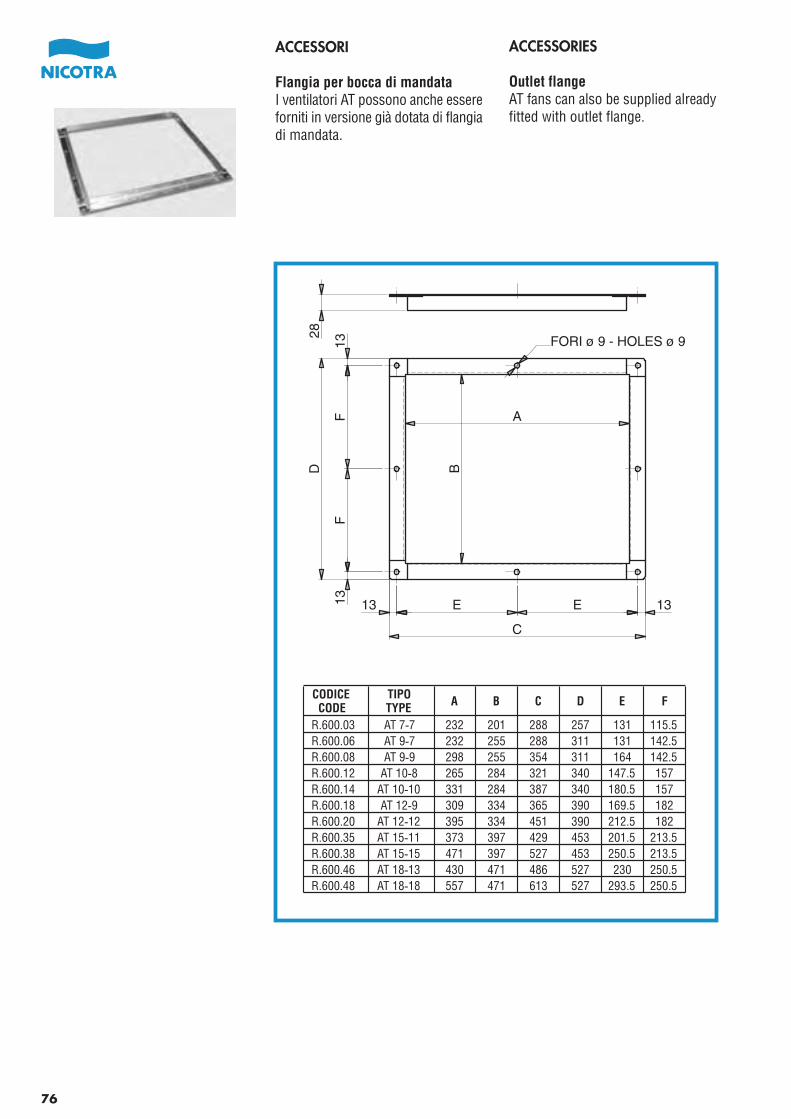
ACCESSORIES
Outlet flangeAT fans can also be supplied alreadyfitted with outlet flange.
ACCESSORI
Flangia per bocca di mandataI ventilatori AT possono anche essereforniti in versione già dotata di flangiadi mandata.
A
B
13 E E 13
C
28D
FF
FORI ø 9 - HOLES ø 91313
76
CODICECODE
TIPOTYPE A B C D E F
R.600.03 AT 7-7 232 201 288 257 131 115.5R.600.06 AT 9-7 232 255 288 311 131 142.5R.600.08 AT 9-9 298 255 354 311 164 142.5R.600.12 AT 10-8 265 284 321 340 147.5 157R.600.14 AT 10-10 331 284 387 340 180.5 157R.600.18 AT 12-9 309 334 365 390 169.5 182R.600.20 AT 12-12 395 334 451 390 212.5 182R.600.35 AT 15-11 373 397 429 453 201.5 213.5R.600.38 AT 15-15 471 397 527 453 250.5 213.5R.600.46 AT 18-13 430 471 486 527 230 250.5R.600.48 AT 18-18 557 471 613 527 293.5 250.5
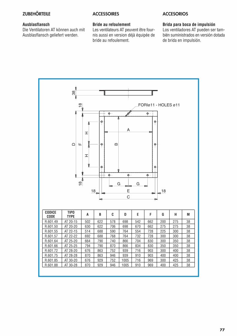
ZUBEHÖRTEILE
AusblasflanschDie Ventilatoren AT können auch mitAusblasflansch geliefert werden.
ACCESSOIRES
Bride au refoulementLes ventilateurs AT peuvent être four-nis aussi en version déjà équipée debride au refoulement.
ACCESORIOS
Brida para boca de impulsiónLos ventiladores AT pueden ser tam-bién suministrados en versión dotadade brida en impulsión.
E
C
18 18
HH
F18
18
D
A
B
38
FORIø11 - HOLES ø11
GG
77
CODICECODE
TIPOTYPE A B C D E F G H M
R.601.49 AT 20-15 502 622 578 698 542 662 200 275 38R.601.50 AT 20-20 630 622 706 698 670 662 275 275 38R.601.55 AT 22-15 514 688 590 764 554 728 225 300 38R.601.57 AT 22-22 692 688 768 764 732 728 300 300 38R.601.64 AT 25-20 664 790 740 866 704 830 300 350 38R.601.66 AT 25-25 794 790 870 866 834 830 350 350 38R.601.72 AT 28-20 676 863 752 939 716 903 300 400 38R.601.75 AT 28-28 870 863 946 939 910 903 400 400 38R.601.85 AT 30-20 676 929 752 1005 716 969 300 425 38R.601.88 AT 30-28 870 929 946 1005 910 969 400 425 38
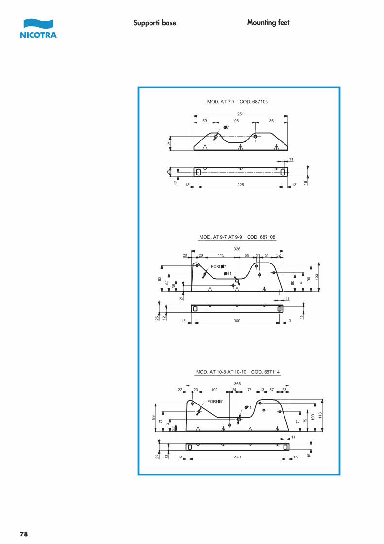
Mounting feetSupporti base
78
10659 86
37
251
7
25
12 16
11
225 1313
MOD. AT 7-7 COD. 687103
30013 1325 12 161121
38
62
92
60 67
90 103
20 28 115 69 11 51 32
326
FORI 7
11
MOD. AT 9-7 AT 9-9 COD. 687108
1334013 16
11
1225
22
43
71
99
7570
100
113
57 331375341092322
366
11
FORI 7
MOD. AT 10-8 AT 10-10 COD. 687114
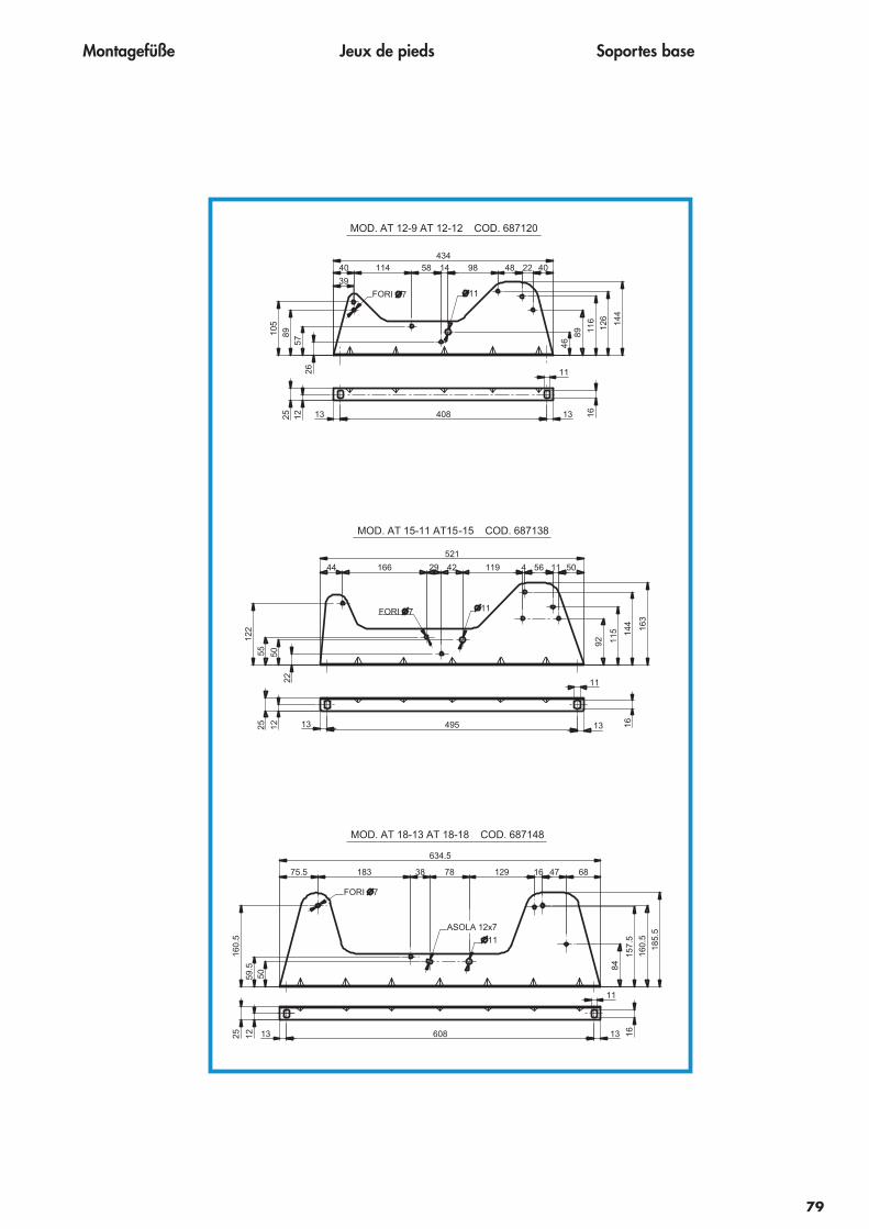
Montagefüße Jeux de pieds Soportes base
79
MOD. AT 12-9 AT 12-12 COD. 687120
40813 13 16
11
1225
2657
89105
46
89 116
126
144
39
40 114 58 14 98 48 22 40434
FORI 7 11
MOD. AT 15-11 AT15-15 COD. 687138
13 495 131225
11
16
22
5055
122
92 115 14
4 163
44 166 29 42 119 4 56 11 50
521
11FORI 7
MOD. AT 18-13 AT 18-18 COD. 687148
131225 608 13 16
11
5059.5
160.
5
84
157.
5
160.
5
185.
5
75.5 38183 78 129 16 6847
634.5
11
ASOLA 12x7
FORI 7
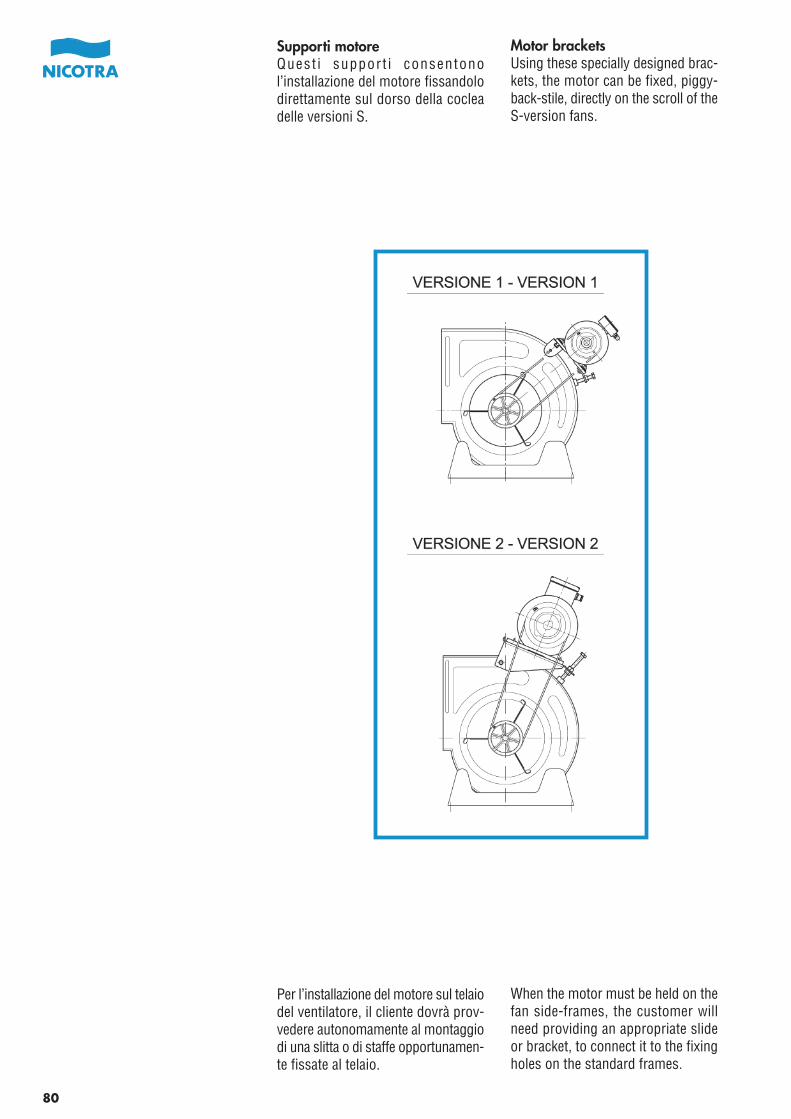
Pag.80-81_Cat_AT_2006 21-04-2006 10:53 Pagina 1
C M Y CM MY CY CMY K
80
Motor bracketsUsing these specially designed brac-kets, the motor can be fixed, piggy-back-stile, directly on the scroll of theS-version fans.
When the motor must be held on thefan side-frames, the customer willneed providing an appropriate slideor bracket, to connect it to the fixingholes on the standard frames.
Supporti motoreQuest i support i consentonol’installazione del motore fissandolodirettamente sul dorso della cocleadelle versioni S.
Per l’installazione del motore sul telaiodel ventilatore, il cliente dovrà prov-vedere autonomamente al montaggiodi una slitta o di staffe opportunamen-te fissate al telaio.
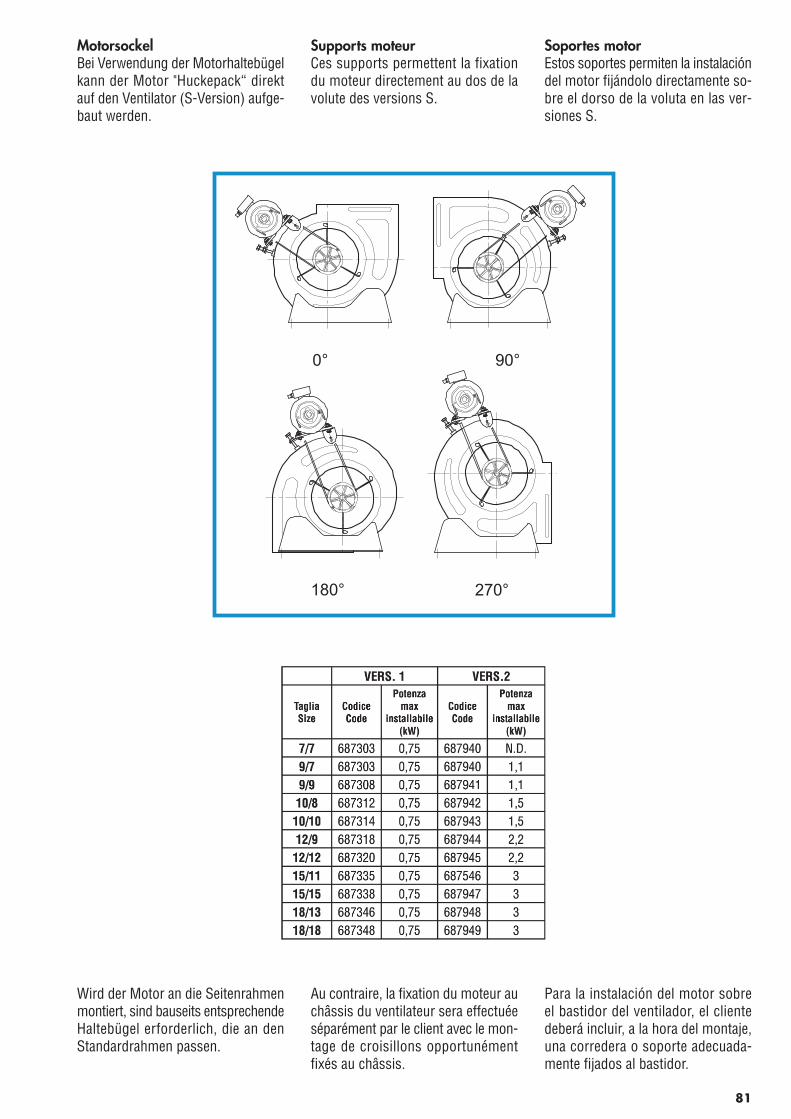
Pag.80-81_Cat_AT_2006 21-04-2006 10:53 Pagina 2
C M Y CM MY CY CMY K
81
90°0°
270°180°
MotorsockelBei Verwendung der Motorhaltebügelkann der Motor "Huckepack“ direktauf den Ventilator (S-Version) aufge-baut werden.
Wird der Motor an die Seitenrahmenmontiert, sind bauseits entsprechendeHaltebügel erforderlich, die an denStandardrahmen passen.
Supports moteurCes supports permettent la fixationdu moteur directement au dos de lavolute des versions S.
Au contraire, la fixation du moteur auchâssis du ventilateur sera effectuéeséparément par le client avec le mon-tage de croisillons opportunémentfixés au châssis.
Soportes motorEstos soportes permiten la instalacióndel motor fijándolo directamente so-bre el dorso de la voluta en las ver-siones S.
Para la instalación del motor sobreel bastidor del ventilador, el clientedeberá incluir, a la hora del montaje,una corredera o soporte adecuada-mente fijados al bastidor.
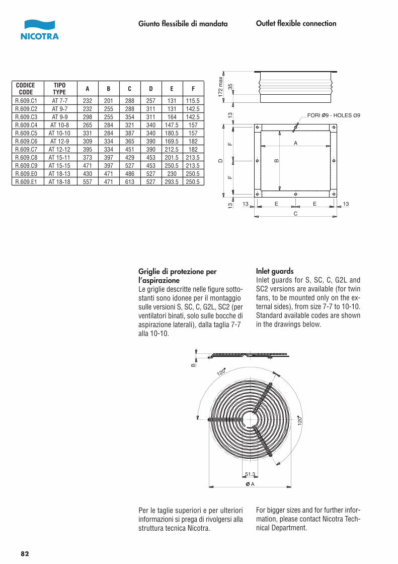
Outlet flexible connection
Inlet guardsInlet guards for S, SC, C, G2L andSC2 versions are available (for twinfans, to be mounted only on the ex-ternal sides), from size 7-7 to 10-10.Standard available codes are shownin the drawings below.
For bigger sizes and for further infor-mation, please contact Nicotra Tech-nical Department.
Giunto flessibile di mandata
Griglie di protezione perl’aspirazioneLe griglie descritte nelle figure sotto-stanti sono idonee per il montaggiosulle versioni S, SC, C, G2L, SC2 (perventilatori binati, solo sulle bocche diaspirazione laterali), dalla taglia 7-7alla 10-10.
Per le taglie superiori e per ulterioriinformazioni si prega di rivolgersi allastruttura tecnica Nicotra.
C
A
B
E E 1313
13F
F13
D17
2 m
ax
35
FORI 9 - HOLES Ø9
A
B
51.3
120
120
82
CODICECODE
TIPOTYPE A B C D E F
R.609.C1 AT 7-7 232 201 288 257 131 115.5R.609.C2 AT 9-7 232 255 288 311 131 142.5R.609.C3 AT 9-9 298 255 354 311 164 142.5R.609.C4 AT 10-8 265 284 321 340 147.5 157R.609.C5 AT 10-10 331 284 387 340 180.5 157R.609.C6 AT 12-9 309 334 365 390 169.5 182R.609.C7 AT 12-12 395 334 451 390 212.5 182R.609.C8 AT 15-11 373 397 429 453 201.5 213.5R.609.C9 AT 15-15 471 397 527 453 250.5 213.5R.609.E0 AT 18-13 430 471 486 527 230 250.5R.609.E1 AT 18-18 557 471 613 527 293.5 250.5
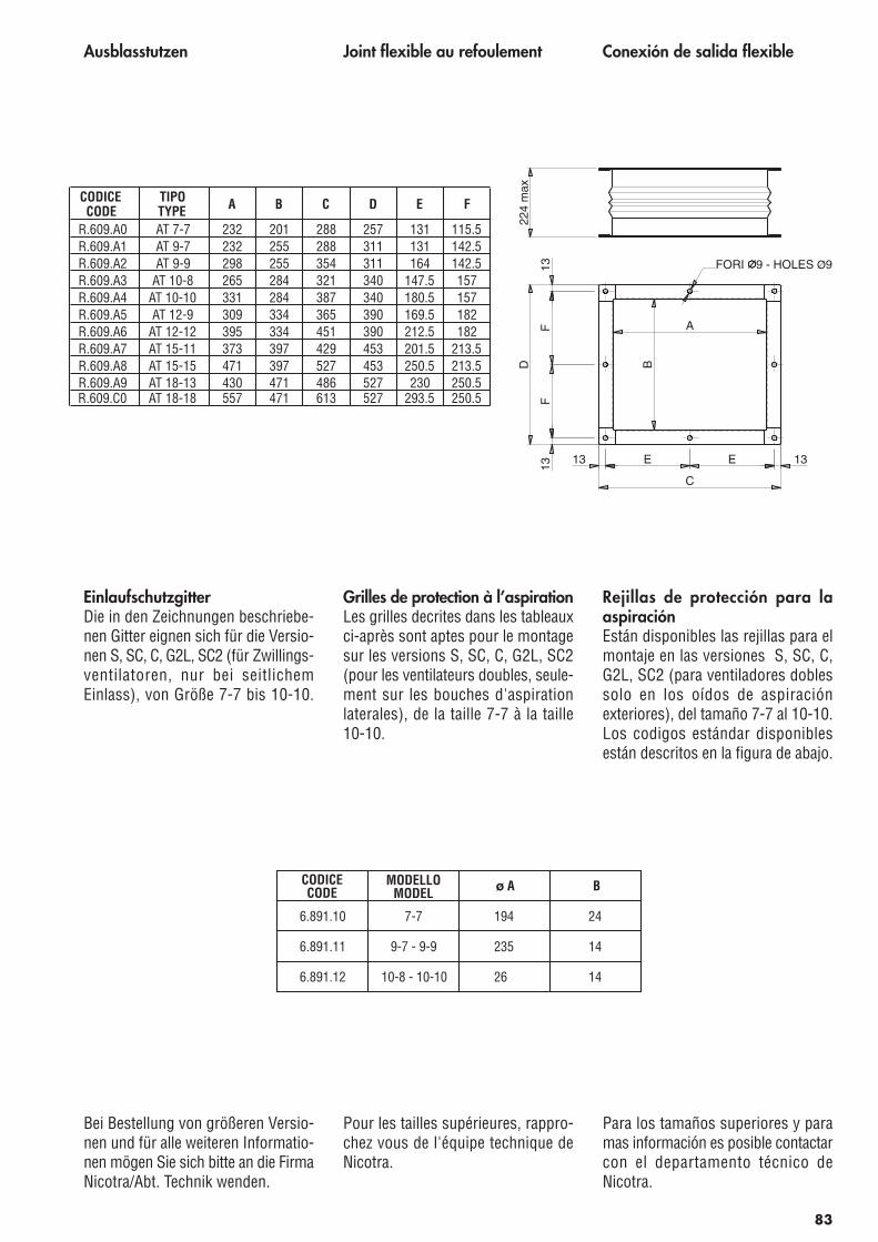
Ausblasstutzen
EinlaufschutzgitterDie in den Zeichnungen beschriebe-nen Gitter eignen sich für die Versio-nen S, SC, C, G2L, SC2 (für Zwillings-ventilatoren, nur bei seitlichemEinlass), von Größe 7-7 bis 10-10.
Bei Bestellung von größeren Versio-nen und für alle weiteren Informatio-nen mögen Sie sich bitte an die FirmaNicotra/Abt. Technik wenden.
Joint flexible au refoulement
Grilles de protection à l’aspirationLes grilles decrites dans les tableauxci-après sont aptes pour le montagesur les versions S, SC, C, G2L, SC2(pour les ventilateurs doubles, seule-ment sur les bouches d'aspirationlaterales), de la taille 7-7 à la taille10-10.
Pour les tailles supérieures, rappro-chez vous de l'équipe technique deNicotra.
Conexión de salida flexible
Rejillas de protección para laaspiraciónEstán disponibles las rejillas para elmontaje en las versiones S, SC, C,G2L, SC2 (para ventiladores doblessolo en los oídos de aspiraciónexteriores), del tamaño 7-7 al 10-10.Los codigos estándar disponiblesestán descritos en la figura de abajo.
Para los tamaños superiores y paramas información es posible contactarcon el departamento técnico deNicotra.
C
A
B
E E 1313
13F
F13
D
FORI 9 - HOLES Ø9
224
max
83
CODICECODE
TIPOTYPE A B C D E F
R.609.A0 AT 7-7 232 201 288 257 131 115.5R.609.A1 AT 9-7 232 255 288 311 131 142.5R.609.A2 AT 9-9 298 255 354 311 164 142.5R.609.A3 AT 10-8 265 284 321 340 147.5 157R.609.A4 AT 10-10 331 284 387 340 180.5 157R.609.A5 AT 12-9 309 334 365 390 169.5 182R.609.A6 AT 12-12 395 334 451 390 212.5 182R.609.A7 AT 15-11 373 397 429 453 201.5 213.5R.609.A8 AT 15-15 471 397 527 453 250.5 213.5R.609.A9 AT 18-13 430 471 486 527 230 250.5R.609.C0 AT 18-18 557 471 613 527 293.5 250.5
241947-76.891.10
6.891.11
6.891.12 10-8 - 10-10
9-7 - 9-9
26
14235
14
CODICECODE
MODELLOMODEL Bo A
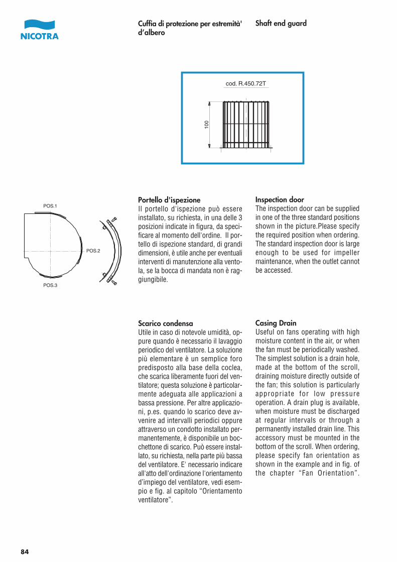
Shaft end guard
Inspection doorThe inspection door can be suppliedin one of the three standard positionsshown in the picture.Please specifythe required position when ordering.The standard inspection door is largeenough to be used for impellermaintenance, when the outlet cannotbe accessed.
Casing DrainUseful on fans operating with highmoisture content in the air, or whenthe fan must be periodically washed.The simplest solution is a drain hole,made at the bottom of the scroll,draining moisture directly outside ofthe fan; this solution is particularlyappropriate for low pressureoperation. A drain plug is available,when moisture must be dischargedat regular intervals or through apermanently installed drain line. Thisaccessory must be mounted in thebottom of the scroll. When ordering,please specify fan orientation asshown in the example and in fig. ofthe chapter “Fan Orientation”.
Cuffia di protezione per estremità'd’albero
Portello d'ispezioneIl portello d'ispezione può essereinstallato, su richiesta, in una delle 3posizioni indicate in figura, da speci-ficare al momento dell'ordine. Il por-tello di ispezione standard, di grandidimensioni, è utile anche per eventualiinterventi di manutenzione alla vento-la, se la bocca di mandata non è rag-giungibile.
Scarico condensaUtile in caso di notevole umidità, op-pure quando è necessario il lavaggioperiodico del ventilatore. La soluzionepiù elementare è un semplice foropredisposto alla base della coclea,che scarica liberamente fuori del ven-tilatore; questa soluzione è particolar-mente adeguata alle applicazioni abassa pressione. Per altre applicazio-ni, p.es. quando lo scarico deve av-venire ad intervalli periodici oppureattraverso un condotto installato per-manentemente, è disponibile un boc-chettone di scarico. Può essere instal-lato, su richiesta, nella parte più bassadel ventilatore. E' necessario indicareall'atto dell'ordinazione l'orientamentod’impiego del ventilatore, vedi esem-pio e fig. al capitolo “Orientamentoventilatore”.
POS.1
POS.2
POS.3
84
100
cod. R.450.72T
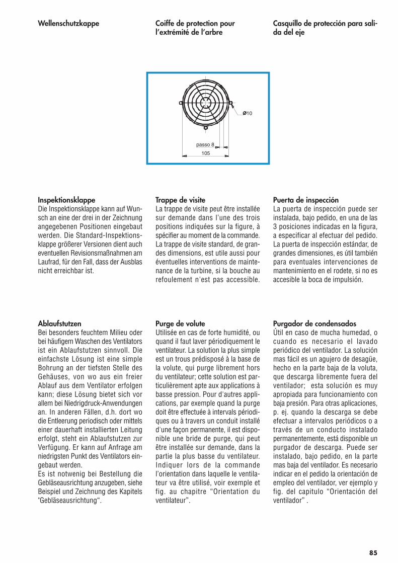
Wellenschutzkappe
InspektionsklappeDie Inspektionsklappe kann auf Wun-sch an eine der drei in der Zeichnungangegebenen Positionen eingebautwerden. Die Standard-Inspektions-klappe größerer Versionen dient aucheventuellen Revisionsmaßnahmen amLaufrad, für den Fall, dass der Ausblasnicht erreichbar ist.
AblaufstutzenBei besonders feuchtem Milieu oderbei häufigem Waschen des Ventilatorsist ein Ablaufstutzen sinnvoll. Dieeinfachste Lösung ist eine simpleBohrung an der tiefsten Stelle desGehäuses, von wo aus ein freierAblauf aus dem Ventilator erfolgenkann; diese Lösung bietet sich vorallem bei Niedrigdruck-Anwendungenan. In anderen Fällen, d.h. dort wodie Entleerung periodisch oder mittelseiner dauerhaft installierten Leitungerfolgt, steht ein Ablaufstutzen zurVerfügung. Er kann auf Anfrage amniedrigsten Punkt des Ventilators ein-gebaut werden.Es ist notwenig bei Bestellung dieGebläseausrichtung anzugeben, sieheBeispiel und Zeichnung des Kapitels"Gebläseausrichtung“.
Coiffe de protection pourl’extrémité de l’arbre
Trappe de visiteLa trappe de visite peut être installéesur demande dans l’une des troispositions indiquées sur la figure, àspécifier au moment de la commande.La trappe de visite standard, de gran-des dimensions, est utile aussi pouréventuelles interventions de mainte-nance de la turbine, si la bouche aurefoulement n'est pas accessible.
Purge de voluteUtilisée en cas de forte humidité, ouquand il faut laver périodiquement leventilateur. La solution la plus simpleest un trous prédisposé à la base dela volute, qui purge librement horsdu ventilateur; cette solution est par-ticulièrement apte aux applications àbasse pression. Pour d'autres appli-cations, par exemple quand la purgedoit être effectuée à intervals périodi-ques ou à travers un conduit installéd'une façon permanente, il est dispo-nible une bride de purge, qui peutêtre installée sur demande, dans lapartie la plus basse du ventilateur.Indiquer lors de la commandel’orientation dans laquelle le ventila-teur va être utilisé, voir exemple etfig. au chapitre “Orientation duventilateur”.
Casquillo de protección para sali-da del eje
Puerta de inspecciónLa puerta de inspección puede serinstalada, bajo pedido, en una de las3 posiciones indicadas en la figura,a especificar al efectuar del pedido.La puerta de inspección estándar, degrandes dimensiones, es útil tambiénpara eventuales intervenciones demantenimiento en el rodete, si no esaccesible la boca de impulsión.
Purgador de condensadosÚtil en caso de mucha humedad, ocuando es necesario el lavadoperiódico del ventilador. La soluciónmas fácil es un agujero de desagüe,hecho en la parte baja de la voluta,que descarga libremente fuera delventilador; esta solución es muyapropiada para funcionamiento conbaja presión. Para otras aplicaciones,p. ej. quando la descarga se debeefectuar a intervalos periódicos o através de un conducto instaladopermanentemente, está disponible unpurgador de descarga. Puede serinstalado, bajo pedido, en la partemas baja del ventilador. Es necesarioindicar en el pedido la orientación deempleo del ventilador, ver ejemplo yfig. del capitulo “Orientación delventilador” .
85
105
passo 8
10
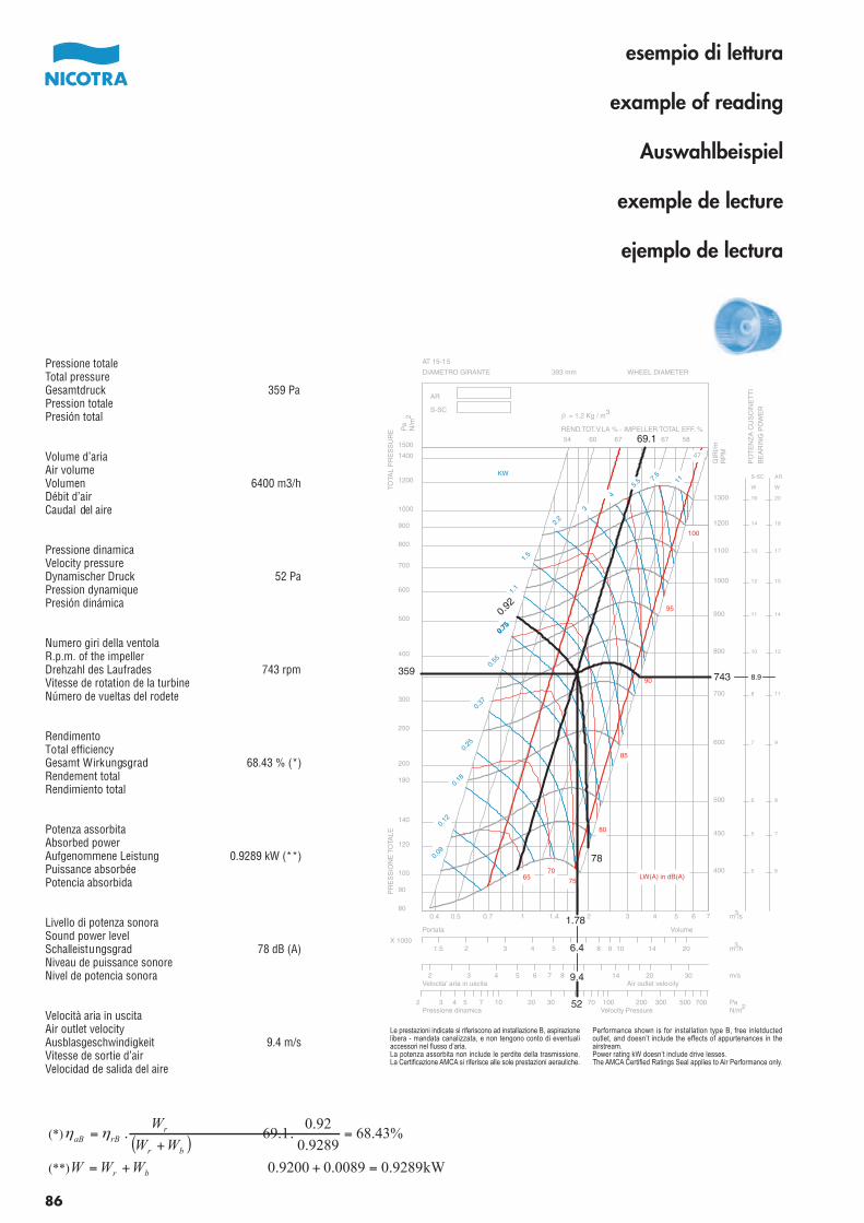
Pressione totaleTotal pressureGesamtdruck 359 PaPression totalePresión total
Volume d’ariaAir volumeVolumen 6400 m3/hDébit d’airCaudal del aire
Pressione dinamicaVelocity pressureDynamischer Druck 52 PaPression dynamiquePresión dinámica
Numero giri della ventolaR.p.m. of the impellerDrehzahl des Laufrades 743 rpmVitesse de rotation de la turbineNúmero de vueltas del rodete
RendimentoTotal efficiencyGesamt Wirkungsgrad 68.43 % (*)Rendement totalRendimiento total
Potenza assorbitaAbsorbed powerAufgenommene Leistung 0.9289 kW (**)Puissance absorbéePotencia absorbida
Livello di potenza sonoraSound power levelSchalleistungsgrad 78 dB (A)Niveau de puissance sonoreNivel de potencia sonora
Velocità aria in uscitaAir outlet velocityAusblasgeschwindigkeit 9.4 m/sVitesse de sortie d’airVelocidad de salida del aire
400
450
500
600
700
800
900
1000
1100
1200
1300
5
5
6
7
8
10
11
12
13
14
16
S-SC
W
6
7
8
9
11
12
14
15
17
18
20
AR
W
0.09
0.12
0.18
0.25
0.37
0.55
0.75
1.1
1.5
2.2
3
45.
5 7.5
11
54 60 67 69.1 67 58
47
6570
75
80
85
90
95
100
0.4 0.5 0.7 1 1.4 2 3 4 5 6 780
90
100
120
140
180
200
250
300
359
400
500
600
700
800
900
1000
1200
1400
1500
PR
ES
SIO
NE
TO
TALE
TO
TAL
PR
ES
SU
RE
DIAMETRO GIRANTE WHEEL DIAMETER393 mm
AT 15-15
AR
S-SC
1.5 2 3 4 5 6.4 8 9 10 14 20X 1000
VolumePortata
2 3 4 5 6 7 8 9.4 14 20 30Velocita' aria in uscita Air outlet velocity
2 3 4 5 7 10 20 30 52 70 100 200 300 500 700Pressione dinamica Velocity Pressure
KW
m /s
GIR
I/mR
PM
Pa
N/m
REND.TOT.V.LA % - IMPELLER TOTAL EFF. %
m /h
m/s
PaN/m
LW(A) in dB(A)
r = 1.2 Kg / m
PO
TE
NZ
A C
US
CIN
ET
TI
BE
AR
ING
PO
WE
R32
3
3
2
0.75
0.75
0.75
0.92
743 8.9
78
1.78
Le prestazioni indicate si riferiscono ad installazione B, aspirazionelibera - mandata canalizzata, e non tengono conto di eventualiaccessori nel flusso d’aria.La potenza assorbita non include le perdite della trasmissione.La Certificazione AMCA si riferisce alle sole prestazioni aerauliche.
Performance shown is for installation type B, free inletductedoutlet, and doesn’t include the effects of appurtenances in theairstream.Power rating kW doesn’t include drive lesses.The AMCA Certified Ratings Seal applies to Air Performance only.
86
esempio di lettura
example of reading
Auswahlbeispiel
exemple de lecture
ejemplo de lectura
(*)( )
%43.680.9289
0.9269.1 =.
+.=
br
rrBaB WW
Wηη
(**) kW9289.00.00890.9200 =++= br WWW
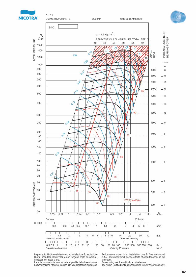
600
700
800
1000
1200
1400
1600
1800
2000
2200
2400
2600
2800
3000
4
5
5
7
8
9
11
12
13
15
16
17
19
20
S-SC
W
0.01
0.02
0.04
0.06
0.12
0.18
0.25
0.37
0.55
0.75 1.
1 1.5 2.
23
4
40 48 56 59 54 42
29
55 60
65
70
75
80
85
90
95
0.05 0.07 0.1 0.14 0.2 0.3 0.5 0.7 1 1.4 230
40
50
60
70
80
90
100
120
140
160
180
200
250
300
400
500
600
700
800
900
1000
1200
1400
1600
PR
ES
SIO
NE
TO
TA
LET
OT
AL
PR
ES
SU
RE
DIAMETRO GIRANTE WHEEL DIAMETER200 mm
AT 7-7
S-SC
0.2 0.3 0.4 0.5 0.7 1 1.4 2 3 4 5 6X 1000
VolumePortata
1 1.4 2 3 4 5 6 7 8 9 10 14 20 30 40Velocita' aria in uscita Air outlet velocity
0.5 0.7 1 2 3 4 5 7 10 20 30 50 70 100 200 300 500700 1000Pressione dinamica Velocity Pressure
KW
m /s
GIR
I/mR
PM
Pa
N/m
REND.TOT.V.LA % - IMPELLER TOTAL EFF. %
m /h
m/s
PaN/m
LW(A) in dB(A)
r = 1.2 Kg / m
PO
TE
NZ
A C
US
CIN
ET
TI
BE
AR
ING
PO
WE
R
3
2
3
3
2
Le prestazioni indicate si riferiscono ad installazione B, aspirazionelibera - mandata canalizzata, e non tengono conto di eventualiaccessori nel flusso d’aria.La potenza assorbita non include le perdite della trasmissione.La Certificazione AMCA si riferisce alle sole prestazioni aerauliche.
Performance shown is for installation type B, free inletductedoutlet, and doesn’t include the effects of appurtenances in theairstream.Power rating kW doesn’t include drive lesses.The AMCA Certified Ratings Seal applies to Air Performance only.
87
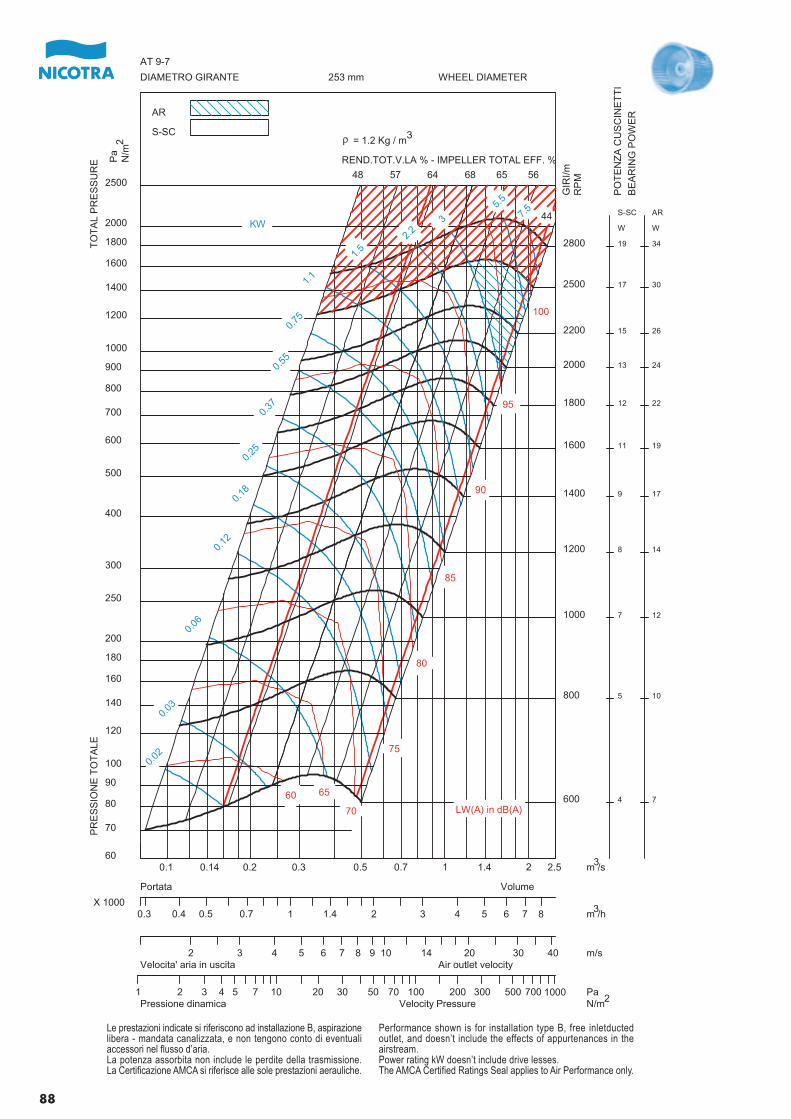
600
800
1000
1200
1400
1600
1800
2000
2200
2500
2800
4
5
7
8
9
11
12
13
15
17
19
S-SC
W
7
10
12
14
17
19
22
24
26
30
34
AR
W
0.02
0.03
0.06
0.12
0.18
0.25
0.37
0.55
0.75
1.1
1.5
2.2
3
5.5
7.5
48 57 64 68 65 56
44
60 65
70
75
80
85
90
95
100
0.1 0.14 0.2 0.3 0.5 0.7 1 1.4 2 2.560
70
80
90
100
120
140
160
180
200
250
300
400
500
600
700
800
900
1000
1200
1400
1600
1800
2000
2500
PR
ES
SIO
NE
TO
TA
LET
OT
AL
PR
ES
SU
RE
DIAMETRO GIRANTE WHEEL DIAMETER253 mm
AT 9-7
AR
S-SC
0.3 0.4 0.5 0.7 1 1.4 2 3 4 5 6 7 8X 1000
VolumePortata
2 3 4 5 6 7 8 9 10 14 20 30 40Velocita' aria in uscita Air outlet velocity
1 2 3 4 5 7 10 20 30 50 70 100 200 300 500 700 1000Pressione dinamica Velocity Pressure
KW
m /s
GIR
I/mR
PM
Pa
N/m
REND.TOT.V.LA % - IMPELLER TOTAL EFF. %
m /h
m/s
PaN/m
LW(A) in dB(A)
r = 1.2 Kg / m
PO
TE
NZ
A C
US
CIN
ET
TI
BE
AR
ING
PO
WE
R
3
2
3
3
2
Le prestazioni indicate si riferiscono ad installazione B, aspirazionelibera - mandata canalizzata, e non tengono conto di eventualiaccessori nel flusso d’aria.La potenza assorbita non include le perdite della trasmissione.La Certificazione AMCA si riferisce alle sole prestazioni aerauliche.
Performance shown is for installation type B, free inletductedoutlet, and doesn’t include the effects of appurtenances in theairstream.Power rating kW doesn’t include drive lesses.The AMCA Certified Ratings Seal applies to Air Performance only.
88
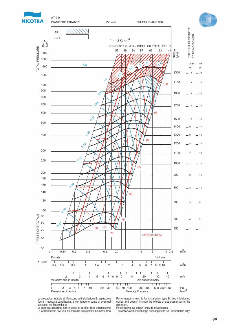
550
600
700
800
900
1000
1100
1200
1300
1400
1500
1700
1900
2100
2300
4
4
5
5
6
7
7
8
9
9
10
11
13
14
15
S-SC
W
7
7
8
10
11
12
13
14
16
17
18
20
23
25
28
AR
W
0.02
0.03
0.06
0.12
0.18
0.25
0.37
0.55
0.75
1.1
1.5
2.2
34
7.5
53 59 64 6767 63 53 41
60 65
70
75
80
85
90
95
100
0.1 0.14 0.2 0.3 0.5 0.7 1 1.4 2 3 3.550
60
70
80
90
100
120
140
160
180
200
250
300
400
500
600
700
800
900
1000
1200
1400
1600
1800
PR
ES
SIO
NE
TO
TA
LET
OT
AL
PR
ES
SU
RE
DIAMETRO GIRANTE WHEEL DIAMETER253 mm
AT 9-9
AR
S-SC
0.4 0.5 0.7 1 1.4 2 3 4 5 6 7 8 9 10X 1000
VolumePortata
2 3 4 5 6 7 8 9 10 14 20 30 40Velocita' aria in uscita Air outlet velocity
1 2 3 4 5 7 10 20 30 50 70 100 200 300 500 700 1000Pressione dinamica Velocity Pressure
KW
m /s
GIR
I/mR
PM
Pa
N/m
REND.TOT.V.LA % - IMPELLER TOTAL EFF. %
m /h
m/s
PaN/m
LW(A) in dB(A)
r = 1.2 Kg / m
PO
TE
NZ
A C
US
CIN
ET
TI
BE
AR
ING
PO
WE
R
3
2
3
3
2
Le prestazioni indicate si riferiscono ad installazione B, aspirazionelibera - mandata canalizzata, e non tengono conto di eventualiaccessori nel flusso d’aria.La potenza assorbita non include le perdite della trasmissione.La Certificazione AMCA si riferisce alle sole prestazioni aerauliche.
Performance shown is for installation type B, free inletductedoutlet, and doesn’t include the effects of appurtenances in theairstream.Power rating kW doesn’t include drive lesses.The AMCA Certified Ratings Seal applies to Air Performance only.
89
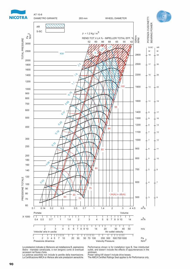
500
600
700
800
900
1000
1100
1200
1300
1400
1600
1900
2200
2500
2800
3
4
5
5
6
7
7
8
9
9
11
13
15
17
19
S-SC
W
6
7
8
10
11
12
13
14
16
17
19
23
26
30
34
AR
W
0.03
0.06
0.12
0.18
0.25
0.37
0.55
0.75
1.1
1.5
2.2
3
45.
5 7.5
52 60 66 68 65 55 42
6065
70
75
80
85
90
95
100
0.1 0.14 0.2 0.3 0.5 0.7 1 1.4 2 3 4 4.560
70
80
90
100
120
140
160
180
200
250
300
400
500
600
700
800
900
1000
1200
1400
1600
1800
2000
2500
3000
PR
ES
SIO
NE
TO
TA
LET
OT
AL
PR
ES
SU
RE
DIAMETRO GIRANTE WHEEL DIAMETER283 mm
AT 10-8
AR
S-SC
0.4 0.5 0.7 1 1.4 2 3 4 5 6 7 8 9 10 14X 1000
VolumePortata
2 3 4 5 6 7 8 9 10 14 20 30 40 50Velocita' aria in uscita Air outlet velocity
1 2 3 4 5 7 10 20 30 50 70 100 200 300 500 7001000Pressione dinamica Velocity Pressure
KW
m /s
GIR
I/mR
PMP
aN
/m
REND.TOT.V.LA % - IMPELLER TOTAL EFF. %
m /h
m/s
PaN/m
LW(A) in dB(A)
r = 1.2 Kg / m
PO
TE
NZ
A C
US
CIN
ET
TI
BE
AR
ING
PO
WE
R
3
2
3
3
2
Le prestazioni indicate si riferiscono ad installazione B, aspirazionelibera - mandata canalizzata, e non tengono conto di eventualiaccessori nel flusso d’aria.La potenza assorbita non include le perdite della trasmissione.La Certificazione AMCA si riferisce alle sole prestazioni aerauliche.
Performance shown is for installation type B, free inletductedoutlet, and doesn’t include the effects of appurtenances in theairstream.Power rating kW doesn’t include drive lesses.The AMCA Certified Ratings Seal applies to Air Performance only.
90
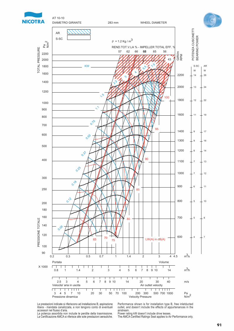
600
700
800
900
1000
1100
1200
1300
1400
1600
1800
2000
2200
4
5
5
6
7
7
8
9
9
11
12
13
14
S-SC
W
7
8
10
11
12
13
14
16
17
19
22
24
26
AR
W
0.06
0.12
0.18
0.25
0.37
0.55
0.75
1.1
1.5
2.2
3
45.
5 7.5
57 62 66 6868 65 56
43
65 7075
80
85
90
95
100
0.2 0.3 0.5 0.7 1 1.4 2 3 4 4.590
100
120
140
160
180
200
250
300
400
500
600
700
800
900
1000
1200
1400
1600
1800
2000
2200
PR
ES
SIO
NE
TO
TA
LET
OT
AL
PR
ES
SU
RE
DIAMETRO GIRANTE WHEEL DIAMETER283 mm
AT 10-10
AR
S-SC
0.8 1 1.4 2 3 4 5 6 7 8 9 10 14X 1000
VolumePortata
2.5 3 4 5 6 7 8 9 10 14 20 30 40Velocita' aria in uscita Air outlet velocity
3 4 5 7 10 20 30 50 70 100 200 300 500 700 1000Pressione dinamica Velocity Pressure
KW
m /s
GIR
I/mR
PM
Pa
N/m
REND.TOT.V.LA % - IMPELLER TOTAL EFF. %
m /h
m/s
PaN/m
LW(A) in dB(A)
r = 1.2 Kg / m
PO
TE
NZ
A C
US
CIN
ET
TI
BE
AR
ING
PO
WE
R
3
2
3
3
2
Le prestazioni indicate si riferiscono ad installazione B, aspirazionelibera - mandata canalizzata, e non tengono conto di eventualiaccessori nel flusso d’aria.La potenza assorbita non include le perdite della trasmissione.La Certificazione AMCA si riferisce alle sole prestazioni aerauliche.
Performance shown is for installation type B, free inletductedoutlet, and doesn’t include the effects of appurtenances in theairstream.Power rating kW doesn’t include drive lesses.The AMCA Certified Ratings Seal applies to Air Performance only.
91
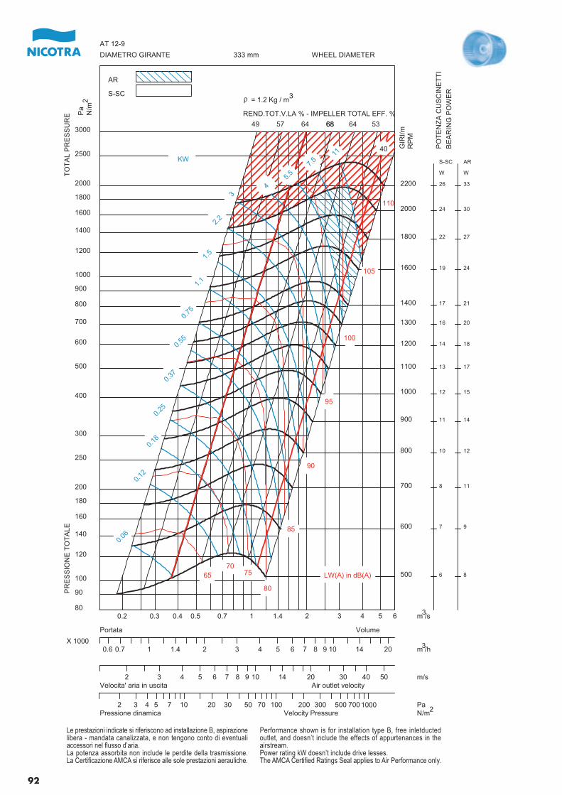
500
600
700
800
900
1000
1100
1200
1300
1400
1600
1800
2000
2200
6
7
8
10
11
12
13
14
16
17
19
22
24
26
S-SC
W
8
9
11
12
14
15
17
18
20
21
24
27
30
33
AR
W
0.06
0.12
0.18
0.25
0.37
0.55
0.75
1.1
1.5
2.2
34
5.5
7.5
11
49 57 64 6868 64 53
40
6570
75
80
85
90
95
100
105
110
0.2 0.3 0.4 0.5 0.7 1 1.4 2 3 4 5 680
90
100
120
140
160
180
200
250
300
400
500
600
700
800
900
1000
1200
1400
1600
1800
2000
2500
3000
PR
ES
SIO
NE
TO
TA
LET
OT
AL
PR
ES
SU
RE
DIAMETRO GIRANTE WHEEL DIAMETER333 mm
AT 12-9
AR
S-SC
0.6 0.7 1 1.4 2 3 4 5 6 7 8 9 10 14 20X 1000
VolumePortata
2 3 4 5 6 7 8 9 10 14 20 30 40 50Velocita' aria in uscita Air outlet velocity
2 3 4 5 7 10 20 30 50 70 100 200 300 500 7001000Pressione dinamica Velocity Pressure
KW
m /s
GIR
I/mR
PM
Pa
N/m
REND.TOT.V.LA % - IMPELLER TOTAL EFF. %
m /h
m/s
PaN/m
LW(A) in dB(A)
r = 1.2 Kg / m
PO
TE
NZ
A C
US
CIN
ET
TI
BE
AR
ING
PO
WE
R
3
2
3
3
2
Le prestazioni indicate si riferiscono ad installazione B, aspirazionelibera - mandata canalizzata, e non tengono conto di eventualiaccessori nel flusso d’aria.La potenza assorbita non include le perdite della trasmissione.La Certificazione AMCA si riferisce alle sole prestazioni aerauliche.
Performance shown is for installation type B, free inletductedoutlet, and doesn’t include the effects of appurtenances in theairstream.Power rating kW doesn’t include drive lesses.The AMCA Certified Ratings Seal applies to Air Performance only.
92
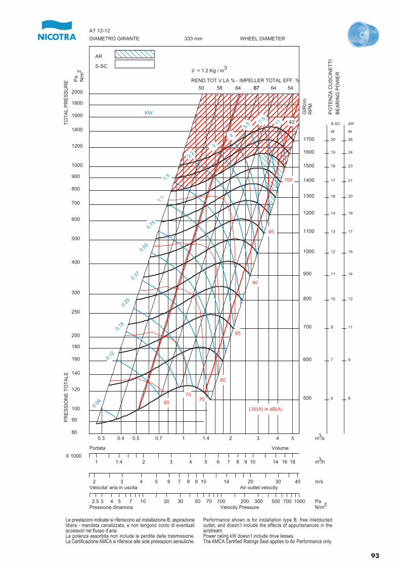
500
600
700
800
900
1000
1100
1200
1300
1400
1500
1600
1700
6
7
8
10
11
12
13
14
16
17
18
19
20
S-SC
W
8
9
11
12
14
15
17
18
20
21
23
24
26
AR
W
0.06
0.12
0.18
0.25
0.37
0.55
0.75
1.1
1.5
2.2
3
4
5.5 7.
511
50 58 64 6767 64 54
42
65
7075
80
85
90
95
100
0.3 0.4 0.5 0.7 1 1.4 2 3 4 580
90
100
120
140
160
180
200
250
300
400
500
600
700
800
900
1000
1200
1400
1600
1800
2000
PR
ES
SIO
NE
TO
TA
LET
OT
AL
PR
ES
SU
RE
DIAMETRO GIRANTE WHEEL DIAMETER333 mm
AT 12-12
AR
S-SC
1 1.4 2 3 4 5 6 7 8 9 10 14 16 18X 1000
VolumePortata
2 3 4 5 6 7 8 9 10 14 20 30 40Velocita' aria in uscita Air outlet velocity
2.5 3 4 5 7 10 20 30 50 70 100 200 300 500 700 1000Pressione dinamica Velocity Pressure
KW
m /s
GIR
I/mR
PM
Pa
N/m
REND.TOT.V.LA % - IMPELLER TOTAL EFF. %
m /h
m/s
PaN/m
LW(A) in dB(A)
r = 1.2 Kg / m
PO
TE
NZ
A C
US
CIN
ET
TI
BE
AR
ING
PO
WE
R
3
2
3
3
2
Le prestazioni indicate si riferiscono ad installazione B, aspirazionelibera - mandata canalizzata, e non tengono conto di eventualiaccessori nel flusso d’aria.La potenza assorbita non include le perdite della trasmissione.La Certificazione AMCA si riferisce alle sole prestazioni aerauliche.
Performance shown is for installation type B, free inletductedoutlet, and doesn’t include the effects of appurtenances in theairstream.Power rating kW doesn’t include drive lesses.The AMCA Certified Ratings Seal applies to Air Performance only.
93
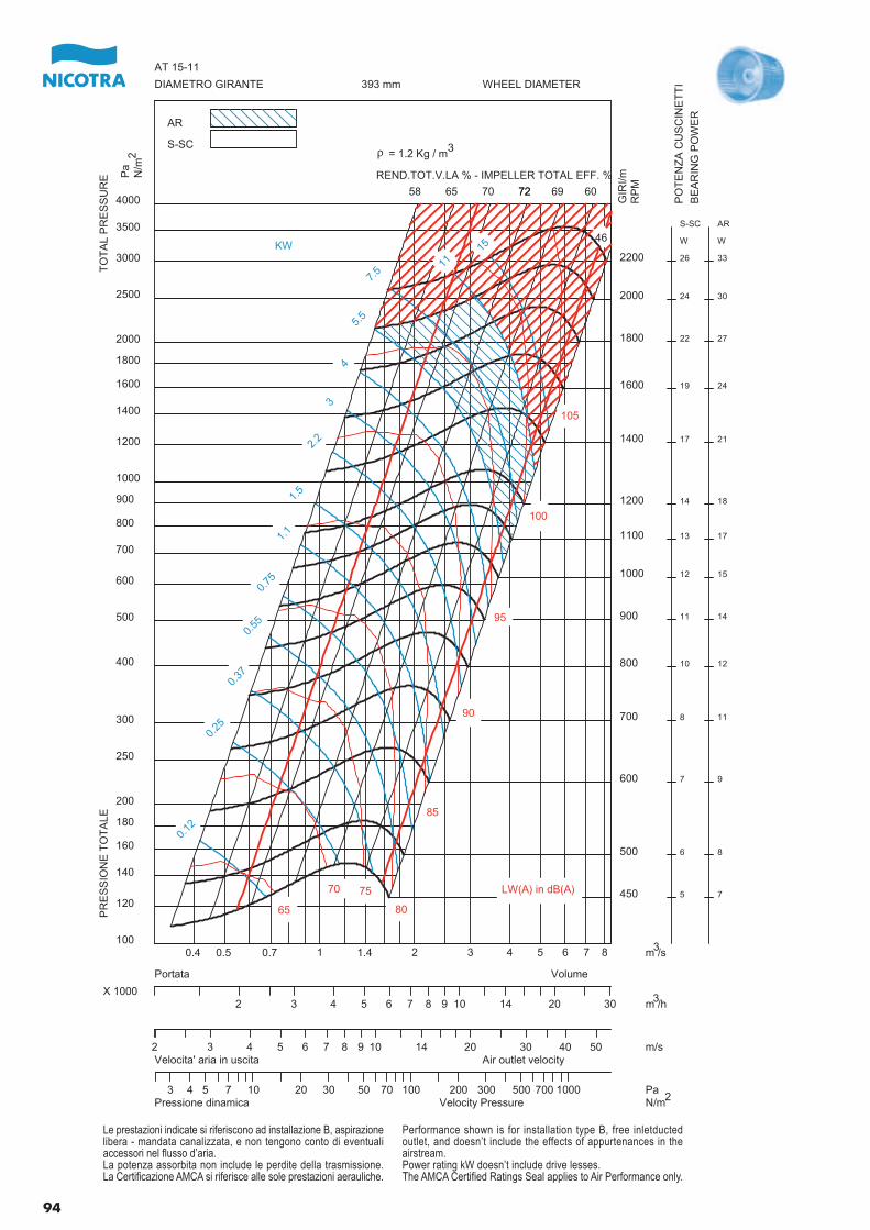
450
500
600
700
800
900
1000
1100
1200
1400
1600
1800
2000
2200
5
6
7
8
10
11
12
13
14
17
19
22
24
26
S-SC
W
7
8
9
11
12
14
15
17
18
21
24
27
30
33
AR
W
0.12
0.25
0.37
0.55
0.75
1.1
1.5
2.2
3
4
5.5
7.5
1115
58 65 70 7272 69 60
46
65
70 75
80
85
90
95
100
105
0.4 0.5 0.7 1 1.4 2 3 4 5 6 7 8100
120
140
160
180
200
250
300
400
500
600
700
800
900
1000
1200
1400
1600
1800
2000
2500
3000
3500
4000
PR
ES
SIO
NE
TO
TA
LET
OT
AL
PR
ES
SU
RE
DIAMETRO GIRANTE WHEEL DIAMETER393 mm
AT 15-11
AR
S-SC
2 3 4 5 6 7 8 9 10 14 20 30X 1000
VolumePortata
2 3 4 5 6 7 8 9 10 14 20 30 40 50Velocita' aria in uscita Air outlet velocity
3 4 5 7 10 20 30 50 70 100 200 300 500 700 1000Pressione dinamica Velocity Pressure
KW
m /s
GIR
I/mR
PM
Pa
N/m
REND.TOT.V.LA % - IMPELLER TOTAL EFF. %
m /h
m/s
PaN/m
LW(A) in dB(A)
r = 1.2 Kg / m
PO
TE
NZ
A C
US
CIN
ET
TI
BE
AR
ING
PO
WE
R
3
2
3
3
2
Le prestazioni indicate si riferiscono ad installazione B, aspirazionelibera - mandata canalizzata, e non tengono conto di eventualiaccessori nel flusso d’aria.La potenza assorbita non include le perdite della trasmissione.La Certificazione AMCA si riferisce alle sole prestazioni aerauliche.
Performance shown is for installation type B, free inletductedoutlet, and doesn’t include the effects of appurtenances in theairstream.Power rating kW doesn’t include drive lesses.The AMCA Certified Ratings Seal applies to Air Performance only.
94
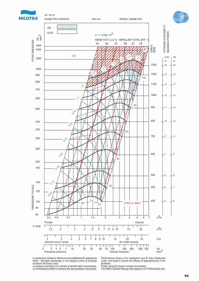
400
450
500
600
700
800
900
1000
1100
1200
1300
5
5
6
7
8
10
11
12
13
14
16
S-SC
W
6
7
8
9
11
12
14
15
17
18
20
AR
W
0.09
0.12
0.18
0.25
0.37
0.55
0.75
1.1
1.5
2.2
3
4
5.5 7.
511
54 60 67 7070 67 58
47
6570
75
80
85
90
95
100
0.4 0.5 0.7 1 1.4 2 3 4 5 6 780
90
100
120
140
180
200
250
300
350
400
500
600
700
800
900
1000
1200
1400
1500
PR
ES
SIO
NE
TO
TA
LET
OT
AL
PR
ES
SU
RE
DIAMETRO GIRANTE WHEEL DIAMETER393 mm
AT 15-15
AR
S-SC
1.5 2 3 4 5 6 7 8 9 10 14 20X 1000
VolumePortata
2 3 4 5 6 7 8 9 10 14 20 30Velocita' aria in uscita Air outlet velocity
2 3 4 5 7 10 20 30 50 70 100 200 300 500 700Pressione dinamica Velocity Pressure
KW
m /s
GIR
I/mR
PM
Pa
N/m
REND.TOT.V.LA % - IMPELLER TOTAL EFF. %
m /h
m/s
PaN/m
LW(A) in dB(A)
r = 1.2 Kg / m
PO
TE
NZ
A C
US
CIN
ET
TI
BE
AR
ING
PO
WE
R3
2
3
3
2
Le prestazioni indicate si riferiscono ad installazione B, aspirazionelibera - mandata canalizzata, e non tengono conto di eventualiaccessori nel flusso d’aria.La potenza assorbita non include le perdite della trasmissione.La Certificazione AMCA si riferisce alle sole prestazioni aerauliche.
Performance shown is for installation type B, free inletductedoutlet, and doesn’t include the effects of appurtenances in theairstream.Power rating kW doesn’t include drive lesses.The AMCA Certified Ratings Seal applies to Air Performance only.
95
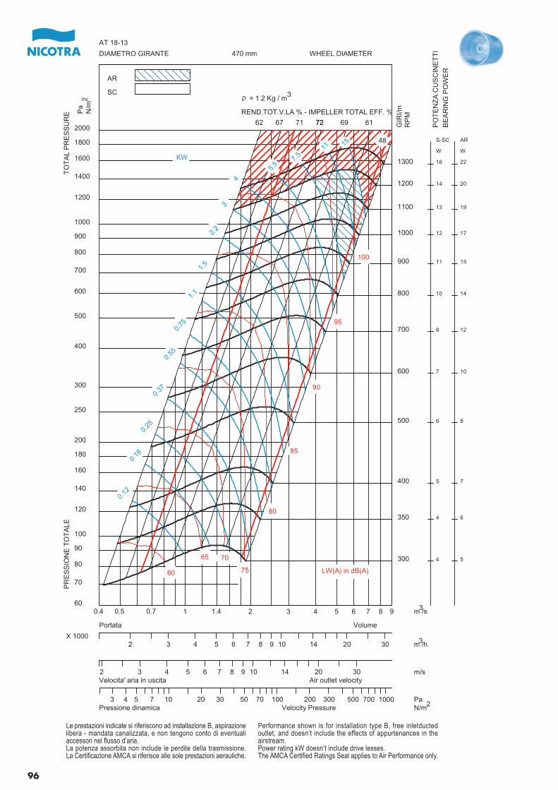
300
350
400
500
600
700
800
900
1000
1100
1200
1300
4
4
5
6
7
8
10
11
12
13
14
16
S-SC
W
5
6
7
8
10
12
14
15
17
19
20
22
AR
W
0.12
0.18
0.25
0.37
0.55
0.75
1.1
1.5
2.2
3
4
5.5
7.5
11 15
62 67 71 7272 69 61
48
60
65 70
75
80
85
90
95
100
0.4 0.5 0.7 1 1.4 2 3 4 5 6 7 8 960
70
80
90
100
120
140
160
180
200
250
300
400
500
600
700
800
900
1000
1200
1400
1600
1800
2000
PR
ES
SIO
NE
TO
TA
LET
OT
AL
PR
ES
SU
RE
DIAMETRO GIRANTE WHEEL DIAMETER470 mm
AT 18-13
AR
SC
2 3 4 5 6 7 8 9 10 14 20 30X 1000
VolumePortata
2 3 4 5 6 7 8 9 10 14 20 30Velocita' aria in uscita Air outlet velocity
3 4 5 7 10 20 30 50 70 100 200 300 500 700 1000Pressione dinamica Velocity Pressure
KW
m /s
GIR
I/mR
PM
Pa
N/m
REND.TOT.V.LA % - IMPELLER TOTAL EFF. %
m /h
m/s
PaN/m
LW(A) in dB(A)
r = 1.2 Kg / m
PO
TE
NZ
A C
US
CIN
ET
TI
BE
AR
ING
PO
WE
R
3
2
3
3
2
Le prestazioni indicate si riferiscono ad installazione B, aspirazionelibera - mandata canalizzata, e non tengono conto di eventualiaccessori nel flusso d’aria.La potenza assorbita non include le perdite della trasmissione.La Certificazione AMCA si riferisce alle sole prestazioni aerauliche.
Performance shown is for installation type B, free inletductedoutlet, and doesn’t include the effects of appurtenances in theairstream.Power rating kW doesn’t include drive lesses.The AMCA Certified Ratings Seal applies to Air Performance only.
96
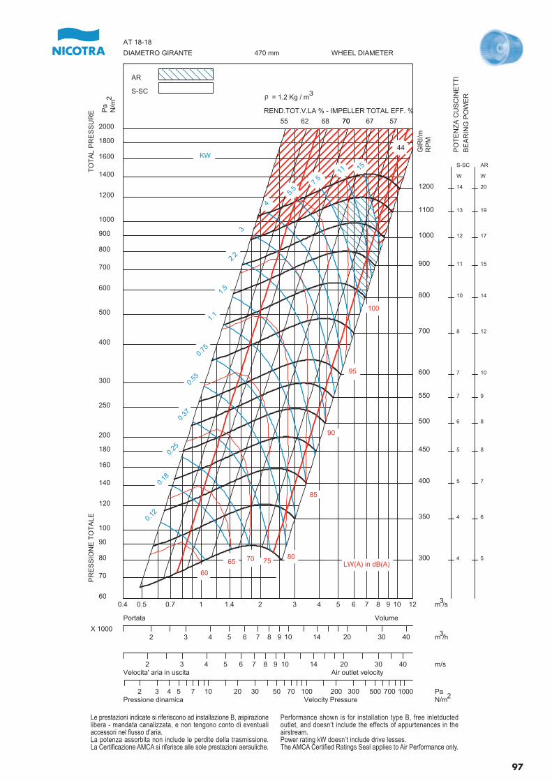
300
350
400
450
500
550
600
700
800
900
1000
1100
1200
4
4
5
5
6
7
7
8
10
11
12
13
14
S-SC
W
5
6
7
8
8
9
10
12
14
15
17
19
20
AR
W
0.12
0.18
0.25
0.37
0.55
0.75
1.1
1.5
2.2
3
4
5.5
7.5
11 15
55 62 68 7070 67 57
44
60
65 70 7580
85
90
95
100
0.4 0.5 0.7 1 1.4 2 3 4 5 6 7 8 9 10 1260
70
80
90
100
120
140
160
180
200
250
300
400
500
600
700
800
900
1000
1200
1400
1600
1800
2000
PR
ES
SIO
NE
TO
TA
LET
OT
AL
PR
ES
SU
RE
DIAMETRO GIRANTE WHEEL DIAMETER470 mm
AT 18-18
AR
S-SC
2 3 4 5 6 7 8 9 10 14 20 30 40X 1000
VolumePortata
2 3 4 5 6 7 8 9 10 14 20 30 40Velocita' aria in uscita Air outlet velocity
2 3 4 5 7 10 20 30 50 70 100 200 300 500 700 1000Pressione dinamica Velocity Pressure
KW
m /s
GIR
I/mR
PM
Pa
N/m
REND.TOT.V.LA % - IMPELLER TOTAL EFF. %
m /h
m/s
PaN/m
LW(A) in dB(A)
r = 1.2 Kg / m
PO
TE
NZ
A C
US
CIN
ET
TI
BE
AR
ING
PO
WE
R3
2
3
3
2
Le prestazioni indicate si riferiscono ad installazione B, aspirazionelibera - mandata canalizzata, e non tengono conto di eventualiaccessori nel flusso d’aria.La potenza assorbita non include le perdite della trasmissione.La Certificazione AMCA si riferisce alle sole prestazioni aerauliche.
Performance shown is for installation type B, free inletductedoutlet, and doesn’t include the effects of appurtenances in theairstream.Power rating kW doesn’t include drive lesses.The AMCA Certified Ratings Seal applies to Air Performance only.
97
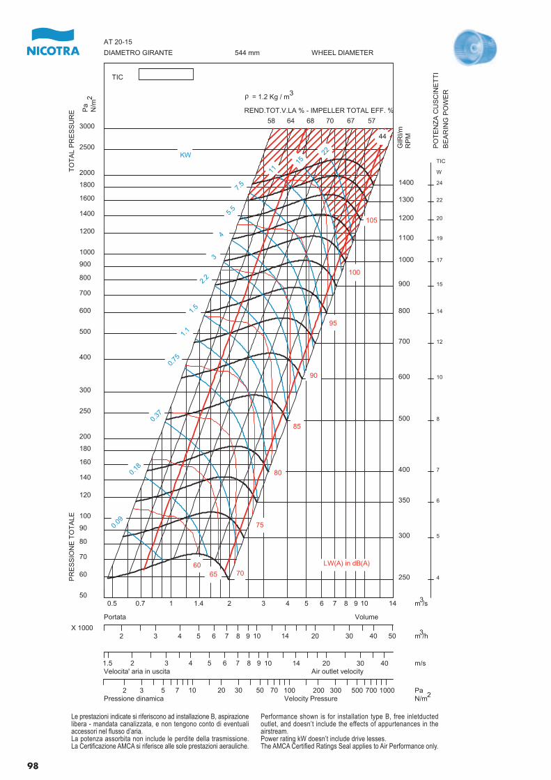
250
300
350
400
500
600
700
800
900
1000
1100
1200
1300
1400
4
5
6
7
8
10
12
14
15
17
19
20
22
24
TIC
W
0.09
0.18
0.37
0.75
1.1
1.5
2.2
3
4
5.5
7.5
1115
22
58 64 68 70 67 57
44
6065 70
75
80
85
90
95
100
105
0.5 0.7 1 1.4 2 3 4 5 6 7 8 9 10 1450
60
70
80
90
100
120
140
160
180
200
250
300
400
500
600
700
800
900
1000
1200
1400
1600
1800
2000
2500
3000
PR
ES
SIO
NE
TO
TA
LET
OT
AL
PR
ES
SU
RE
DIAMETRO GIRANTE WHEEL DIAMETER544 mm
AT 20-15
TIC
2 3 4 5 6 7 8 9 10 14 20 30 40 50X 1000
VolumePortata
1.5 2 3 4 5 6 7 8 9 10 14 20 30 40Velocita' aria in uscita Air outlet velocity
2 3 5 7 10 20 30 50 70 100 200 300 500 700 1000Pressione dinamica Velocity Pressure
KW
m /s
GIR
I/mR
PM
Pa
N/m
REND.TOT.V.LA % - IMPELLER TOTAL EFF. %
m /h
m/s
PaN/m
LW(A) in dB(A)
r = 1.2 Kg / m
PO
TE
NZ
A C
US
CIN
ET
TI
BE
AR
ING
PO
WE
R32
3
3
2
Le prestazioni indicate si riferiscono ad installazione B, aspirazionelibera - mandata canalizzata, e non tengono conto di eventualiaccessori nel flusso d’aria.La potenza assorbita non include le perdite della trasmissione.La Certificazione AMCA si riferisce alle sole prestazioni aerauliche.
Performance shown is for installation type B, free inletductedoutlet, and doesn’t include the effects of appurtenances in theairstream.Power rating kW doesn’t include drive lesses.The AMCA Certified Ratings Seal applies to Air Performance only.
98
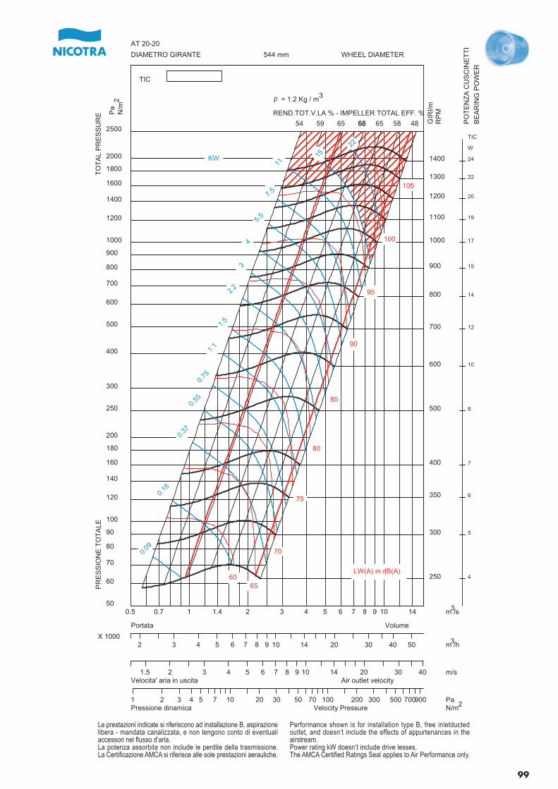
250
300
350
400
500
600
700
800
900
1000
1100
1200
1300
1400
4
5
6
7
8
10
12
14
15
17
19
20
22
24
TIC
W
0.09
0.18
0.37
0.55
0.75
1.1
1.5
2.2
3
4
5.5
7.5
1115
22
54 59 65 6868 65 58 48
6065
70
75
80
85
90
95
100
105
0.5 0.7 1 1.4 2 3 4 5 6 7 8 9 10 1450
60
70
80
90
100
120
140
160
180
200
250
300
400
500
600
700
800
900
1000
1200
1400
1600
1800
2000
2500
PR
ES
SIO
NE
TO
TA
LET
OT
AL
PR
ES
SU
RE
DIAMETRO GIRANTE WHEEL DIAMETER544 mm
AT 20-20
TIC
2 3 4 5 6 7 8 9 10 14 20 30 40 50X 1000
VolumePortata
1.5 2 3 4 5 6 7 8 9 10 14 20 30 40Velocita' aria in uscita Air outlet velocity
1 2 3 4 5 7 10 20 30 50 70 100 200 300 500 700900Pressione dinamica Velocity Pressure
KW
m /s
GIR
I/mR
PMP
aN
/mREND.TOT.V.LA % - IMPELLER TOTAL EFF. %
m /h
m/s
PaN/m
LW(A) in dB(A)
r = 1.2 Kg / m
PO
TE
NZ
A C
US
CIN
ET
TI
BE
AR
ING
PO
WE
R
3
2
3
3
2
Le prestazioni indicate si riferiscono ad installazione B, aspirazionelibera - mandata canalizzata, e non tengono conto di eventualiaccessori nel flusso d’aria.La potenza assorbita non include le perdite della trasmissione.La Certificazione AMCA si riferisce alle sole prestazioni aerauliche.
Performance shown is for installation type B, free inletductedoutlet, and doesn’t include the effects of appurtenances in theairstream.Power rating kW doesn’t include drive lesses.The AMCA Certified Ratings Seal applies to Air Performance only.
99
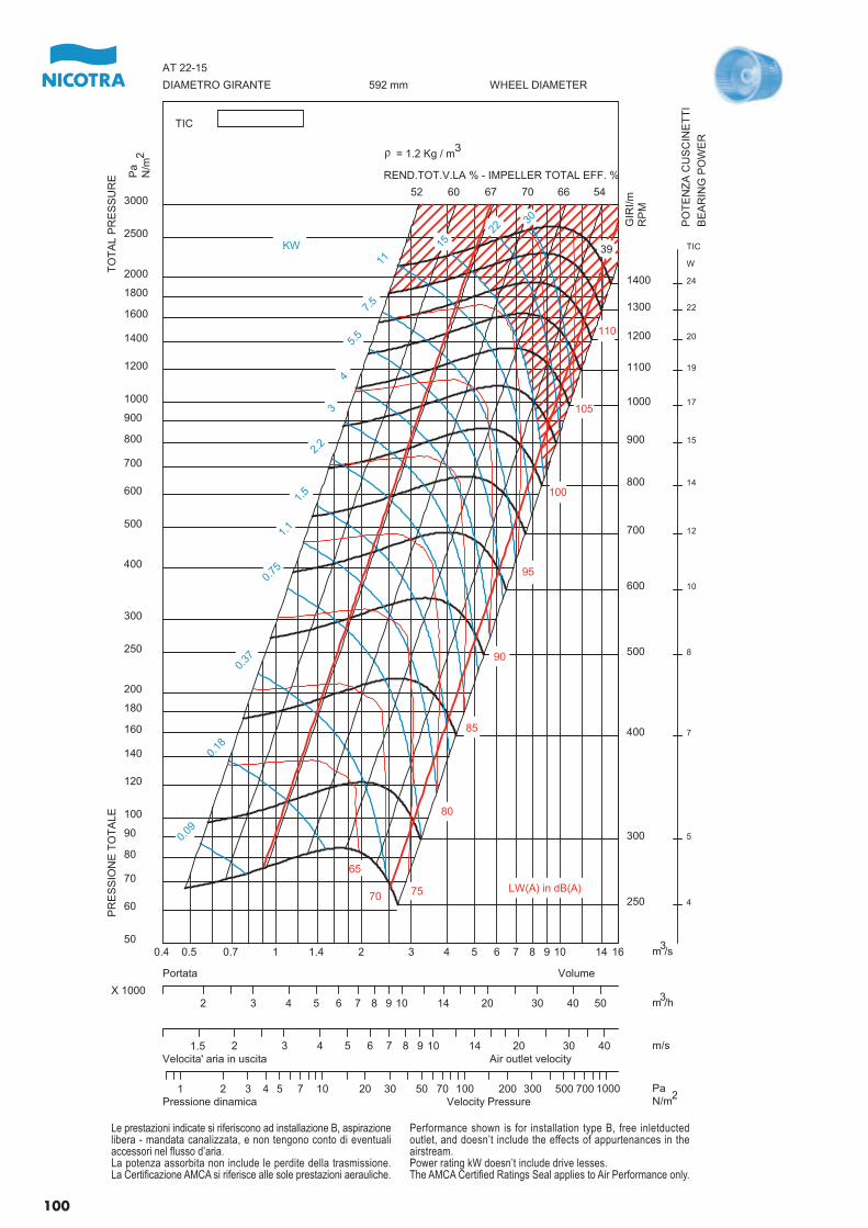
250
300
400
500
600
700
800
900
1000
1100
1200
1300
1400
4
5
7
8
10
12
14
15
17
19
20
22
24
TIC
W
0.09
0.18
0.37
0.75
1.1
1.5
2.2
3
4
5.5
7.5
1115
2230
52 60 67 70 66 54
39
65
70 75
80
85
90
95
100
105
110
0.4 0.5 0.7 1 1.4 2 3 4 5 6 7 8 9 10 14 1650
60
70
80
90
100
120
140
160
180
200
250
300
400
500
600
700
800
900
1000
1200
1400
1600
1800
2000
2500
3000
PR
ES
SIO
NE
TO
TA
LET
OT
AL
PR
ES
SU
RE
DIAMETRO GIRANTE WHEEL DIAMETER592 mm
AT 22-15
TIC
2 3 4 5 6 7 8 9 10 14 20 30 40 50X 1000
VolumePortata
1.5 2 3 4 5 6 7 8 9 10 14 20 30 40Velocita' aria in uscita Air outlet velocity
1 2 3 4 5 7 10 20 30 50 70 100 200 300 500 700 1000Pressione dinamica Velocity Pressure
KW
m /s
GIR
I/mR
PM
Pa
N/m
REND.TOT.V.LA % - IMPELLER TOTAL EFF. %
m /h
m/s
PaN/m
LW(A) in dB(A)
r = 1.2 Kg / m
PO
TE
NZ
A C
US
CIN
ET
TI
BE
AR
ING
PO
WE
R
32
3
3
2
Le prestazioni indicate si riferiscono ad installazione B, aspirazionelibera - mandata canalizzata, e non tengono conto di eventualiaccessori nel flusso d’aria.La potenza assorbita non include le perdite della trasmissione.La Certificazione AMCA si riferisce alle sole prestazioni aerauliche.
Performance shown is for installation type B, free inletductedoutlet, and doesn’t include the effects of appurtenances in theairstream.Power rating kW doesn’t include drive lesses.The AMCA Certified Ratings Seal applies to Air Performance only.
100
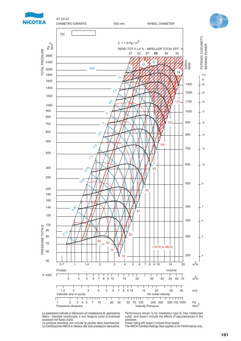
250
300
350
400
500
600
700
800
900
1000
1100
1200
1300
4
5
6
7
9
10
12
14
15
17
19
20
22
TIC
W
0.12
0.25
0.55
0.75
1.1
1.5
2.2
3
4
5.5
7.5
11
1522
30
57 62 67 6969 64 50
34
60 65
70
75
80
85
90
95
100
105
110
0.7 1 1.4 2 3 4 5 6 7 8 9 10 14 2050
60
70
80
90
100
120
140
160
180
200
250
300
400
500
600
700
800
900
1000
1200
1400
1600
1800
2000
2300
2600
PR
ES
SIO
NE
TO
TA
LET
OT
AL
PR
ES
SU
RE
DIAMETRO GIRANTE WHEEL DIAMETER592 mm
AT 22-22
TIC
3 4 5 6 7 8 9 10 14 20 30 40 50 60 70X 1000
VolumePortata
1.5 2 3 4 5 6 7 8 9 10 14 20 30 40Velocita' aria in uscita Air outlet velocity
1 2 3 4 5 7 10 20 30 50 70 100 200 300 500 700 1000Pressione dinamica Velocity Pressure
KW
m /s
GIR
I/mR
PM
Pa
N/m
REND.TOT.V.LA % - IMPELLER TOTAL EFF. %
m /h
m/s
PaN/m
LW(A) in dB(A)
r = 1.2 Kg / m
PO
TE
NZ
A C
US
CIN
ET
TI
BE
AR
ING
PO
WE
R
3
2
3
3
2
Le prestazioni indicate si riferiscono ad installazione B, aspirazionelibera - mandata canalizzata, e non tengono conto di eventualiaccessori nel flusso d’aria.La potenza assorbita non include le perdite della trasmissione.La Certificazione AMCA si riferisce alle sole prestazioni aerauliche.
Performance shown is for installation type B, free inletductedoutlet, and doesn’t include the effects of appurtenances in theairstream.Power rating kW doesn’t include drive lesses.The AMCA Certified Ratings Seal applies to Air Performance only.
101
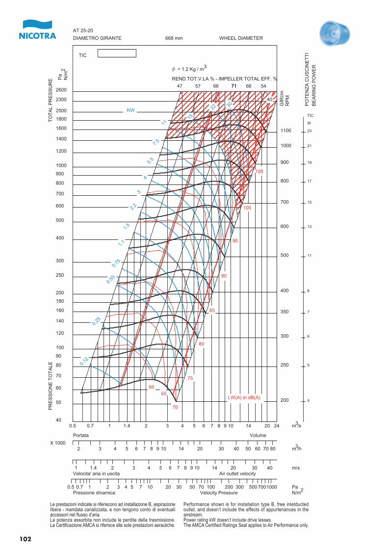
200
250
300
350
400
500
600
700
800
900
1000
1100
4
5
6
7
8
11
13
15
17
19
21
23
TIC
W
0.12
0.25
0.55
0.75
1.1
1.5
2.2
3
4
5.5
7.5
1115
22 30
47 57 66 7171 66 54
40
6065
70
75
80
85
90
95
100
105
0.5 0.7 1 1.4 2 3 4 5 6 7 8 9 10 14 20 2440
50
60
70
80
90
100
120
140
160
180
200
250
300
400
500
600
700
800
900
1000
1200
1400
1600
1800
2000
2300
2600
PR
ES
SIO
NE
TO
TA
LET
OT
AL
PR
ES
SU
RE
DIAMETRO GIRANTE WHEEL DIAMETER668 mm
AT 25-20
TIC
2 3 4 5 6 7 8 9 10 14 20 30 40 50 60 70 80X 1000
VolumePortata
1 1.4 2 3 4 5 6 7 8 9 10 14 20 30 40Velocita' aria in uscita Air outlet velocity
0.5 0.7 1 2 3 4 5 7 10 20 30 50 70 100 200 300 500 7001000Pressione dinamica Velocity Pressure
KW
m /s
GIR
I/mR
PM
Pa
N/m
REND.TOT.V.LA % - IMPELLER TOTAL EFF. %
m /h
m/s
PaN/m
LW(A) in dB(A)
r = 1.2 Kg / m
PO
TE
NZ
A C
US
CIN
ET
TI
BE
AR
ING
PO
WE
R32
3
3
2
Le prestazioni indicate si riferiscono ad installazione B, aspirazionelibera - mandata canalizzata, e non tengono conto di eventualiaccessori nel flusso d’aria.La potenza assorbita non include le perdite della trasmissione.La Certificazione AMCA si riferisce alle sole prestazioni aerauliche.
Performance shown is for installation type B, free inletductedoutlet, and doesn’t include the effects of appurtenances in theairstream.Power rating kW doesn’t include drive lesses.The AMCA Certified Ratings Seal applies to Air Performance only.
102
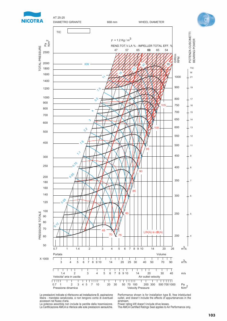
200
250
300
350
400
450
500
550
600
650
700
750
800
900
1000
4
5
6
7
8
9
11
12
13
14
15
16
17
19
21
TIC
W
0.12
0.25
0.55
0.75
1.1
1.5
2.2
3
4
5.5
7.5
1115
2230
47 57 65 6969 65 54
39
65
70 75
80
85
90
95
100
105
0.7 1 1.4 2 3 4 5 6 7 8 9 10 14 20 2650
60
70
80
90
100
120
140
160
180
200
250
300
400
500
600
700
800
900
1000
1200
1400
1600
1800
2000
2500
PR
ES
SIO
NE
TO
TA
LET
OT
AL
PR
ES
SU
RE
DIAMETRO GIRANTE WHEEL DIAMETER668 mm
AT 25-25
TIC
3 4 5 6 7 8 9 10 14 20 25 30 40 50 70 90X 1000
VolumePortata
1.4 2 3 4 5 6 7 8 9 10 14 20 30 40Velocita' aria in uscita Air outlet velocity
0.7 1 2 3 4 5 7 10 20 30 50 70 100 200 300 500 700 1000Pressione dinamica Velocity Pressure
KW
m /s
GIR
I/mR
PM
Pa
N/m
REND.TOT.V.LA % - IMPELLER TOTAL EFF. %
m /h
m/s
PaN/m
LW(A) in dB(A)
r = 1.2 Kg / m
PO
TE
NZ
A C
US
CIN
ET
TI
BE
AR
ING
PO
WE
R3
2
3
3
2
Le prestazioni indicate si riferiscono ad installazione B, aspirazionelibera - mandata canalizzata, e non tengono conto di eventualiaccessori nel flusso d’aria.La potenza assorbita non include le perdite della trasmissione.La Certificazione AMCA si riferisce alle sole prestazioni aerauliche.
Performance shown is for installation type B, free inletductedoutlet, and doesn’t include the effects of appurtenances in theairstream.Power rating kW doesn’t include drive lesses.The AMCA Certified Ratings Seal applies to Air Performance only.
103
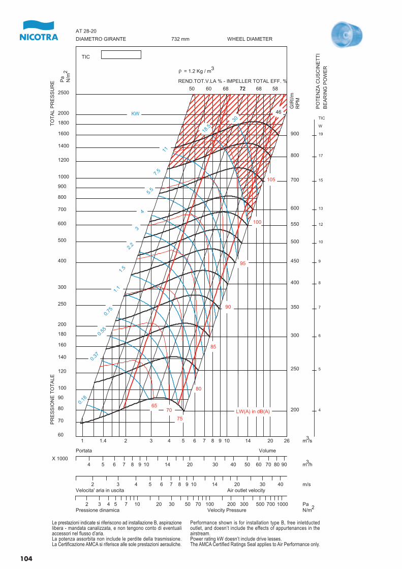
200
250
300
350
400
450
500
550
600
700
800
900
4
5
6
7
8
9
10
12
13
15
17
19
TIC
W
0.18
0.37
0.55
0.75
1.1
1.5
2.2
3
4
5.5
7.5
11
18.5
30
50 60 68 7272 68 58
46
6570
75
80
85
90
95
100
105
1 1.4 2 3 4 5 6 7 8 9 10 14 20 2660
70
80
90
100
120
140
160
180
200
250
300
400
500
600
700
800
900
1000
1200
1400
1600
1800
2000
2500
PR
ES
SIO
NE
TO
TA
LET
OT
AL
PR
ES
SU
RE
DIAMETRO GIRANTE WHEEL DIAMETER732 mm
AT 28-20
TIC
4 5 6 7 8 9 10 14 20 30 40 50 60 70 80 90X 1000
VolumePortata
2 3 4 5 6 7 8 9 10 14 20 30 40Velocita' aria in uscita Air outlet velocity
2 3 4 5 7 10 20 30 50 70 100 200 300 500 700 1000Pressione dinamica Velocity Pressure
KW
m /s
GIR
I/mR
PM
Pa
N/m
REND.TOT.V.LA % - IMPELLER TOTAL EFF. %
m /h
m/s
PaN/m
LW(A) in dB(A)
r = 1.2 Kg / m
PO
TE
NZ
A C
US
CIN
ET
TI
BE
AR
ING
PO
WE
R32
3
3
2
Le prestazioni indicate si riferiscono ad installazione B, aspirazionelibera - mandata canalizzata, e non tengono conto di eventualiaccessori nel flusso d’aria.La potenza assorbita non include le perdite della trasmissione.La Certificazione AMCA si riferisce alle sole prestazioni aerauliche.
Performance shown is for installation type B, free inletductedoutlet, and doesn’t include the effects of appurtenances in theairstream.Power rating kW doesn’t include drive lesses.The AMCA Certified Ratings Seal applies to Air Performance only.
104
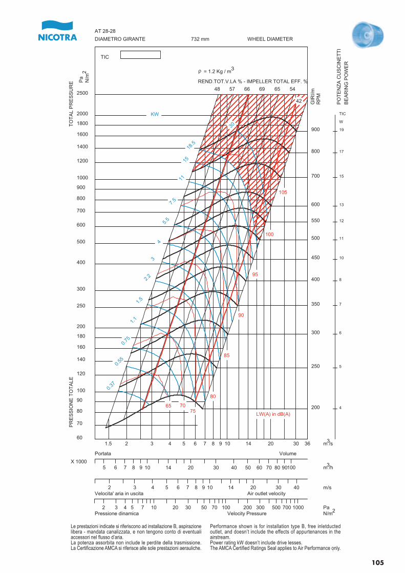
200
250
300
350
400
450
500
550
600
700
800
900
4
5
6
7
8
10
11
12
13
15
17
19
TIC
W
0.37
0.55
0.75
1.1
1.5
2.2
3
4
5.5
7.5
11
15
18.5
30
48 57 66 69 65 54
42
65 7075
80
85
90
95
100
105
1.5 2 3 4 5 6 7 8 9 10 14 20 30 3660
70
80
90
100
120
140
160
180
200
250
300
400
500
600
700
800
900
1000
1200
1400
1600
1800
2000
2500
PR
ES
SIO
NE
TO
TA
LET
OT
AL
PR
ES
SU
RE
DIAMETRO GIRANTE WHEEL DIAMETER732 mm
AT 28-28
TIC
5 6 7 8 9 10 14 20 30 40 50 60 70 80 90100X 1000
VolumePortata
2 3 4 5 6 7 8 9 10 14 20 30 40Velocita' aria in uscita Air outlet velocity
2 3 4 5 7 10 20 30 50 70 100 200 300 500 700 1000Pressione dinamica Velocity Pressure
.
KW
m /s
GIR
I/mR
PM
Pa
N/m
REND.TOT.V.LA % - IMPELLER TOTAL EFF. %
m /h
m/s
PaN/m
LW(A) in dB(A)
r = 1.2 Kg / m
PO
TE
NZ
A C
US
CIN
ET
TI
BE
AR
ING
PO
WE
R
3
2
3
3
2
Le prestazioni indicate si riferiscono ad installazione B, aspirazionelibera - mandata canalizzata, e non tengono conto di eventualiaccessori nel flusso d’aria.La potenza assorbita non include le perdite della trasmissione.La Certificazione AMCA si riferisce alle sole prestazioni aerauliche.
Performance shown is for installation type B, free inletductedoutlet, and doesn’t include the effects of appurtenances in theairstream.Power rating kW doesn’t include drive lesses.The AMCA Certified Ratings Seal applies to Air Performance only.
105
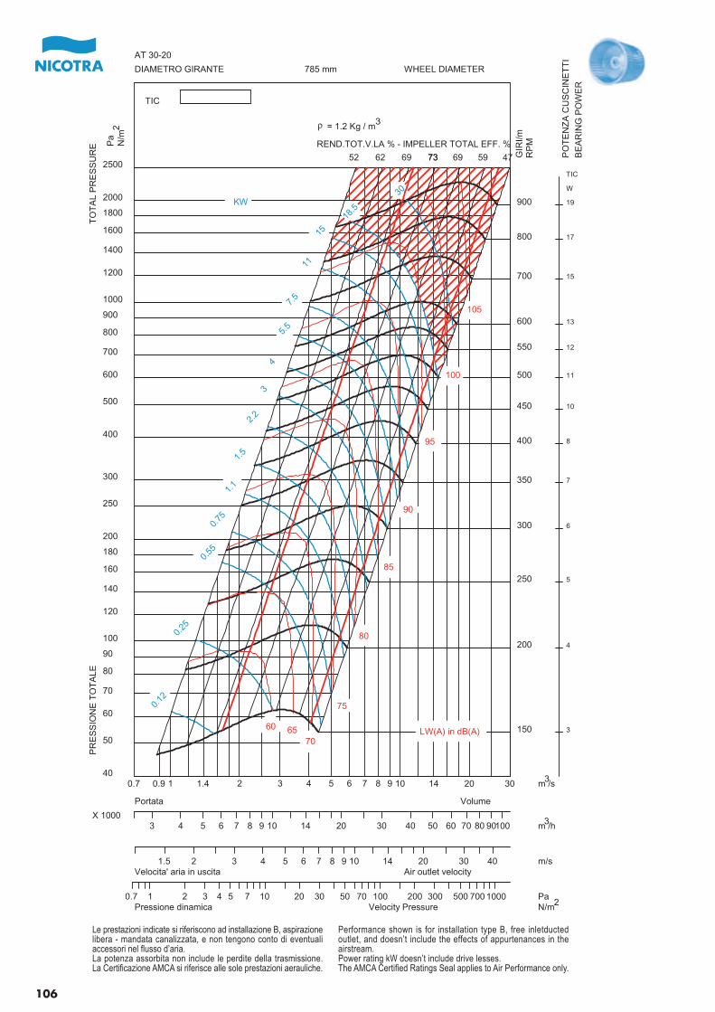
150
200
250
300
350
400
450
500
550
600
700
800
900
3
4
5
6
7
8
10
11
12
13
15
17
19
TIC
W
0.12
0.25
0.55
0.75
1.1
1.5
2.2
3
4
5.5
7.5
11
15
18.5
30
52 62 69 7373 69 59 47
60 6570
75
80
85
90
95
100
105
0.7 0.9 1 1.4 2 3 4 5 6 7 8 9 10 14 20 3040
50
60
70
80
90
100
120
140
160
180
200
250
300
400
500
600
700
800
900
1000
1200
1400
1600
1800
2000
2500
PR
ES
SIO
NE
TO
TA
LET
OT
AL
PR
ES
SU
RE
DIAMETRO GIRANTE WHEEL DIAMETER785 mm
AT 30-20
TIC
3 4 5 6 7 8 9 10 14 20 30 40 50 60 70 80 90100X 1000
VolumePortata
1.5 2 3 4 5 6 7 8 9 10 14 20 30 40Velocita' aria in uscita Air outlet velocity
0.7 1 2 3 4 5 7 10 20 30 50 70 100 200 300 500 700 1000Pressione dinamica Velocity Pressure
KW
m /s
GIR
I/mR
PMP
aN
/m
REND.TOT.V.LA % - IMPELLER TOTAL EFF. %
m /h
m/s
PaN/m
LW(A) in dB(A)
r = 1.2 Kg / m
PO
TE
NZ
A C
US
CIN
ET
TI
BE
AR
ING
PO
WE
R
32
3
3
2
Le prestazioni indicate si riferiscono ad installazione B, aspirazionelibera - mandata canalizzata, e non tengono conto di eventualiaccessori nel flusso d’aria.La potenza assorbita non include le perdite della trasmissione.La Certificazione AMCA si riferisce alle sole prestazioni aerauliche.
Performance shown is for installation type B, free inletductedoutlet, and doesn’t include the effects of appurtenances in theairstream.Power rating kW doesn’t include drive lesses.The AMCA Certified Ratings Seal applies to Air Performance only.
106
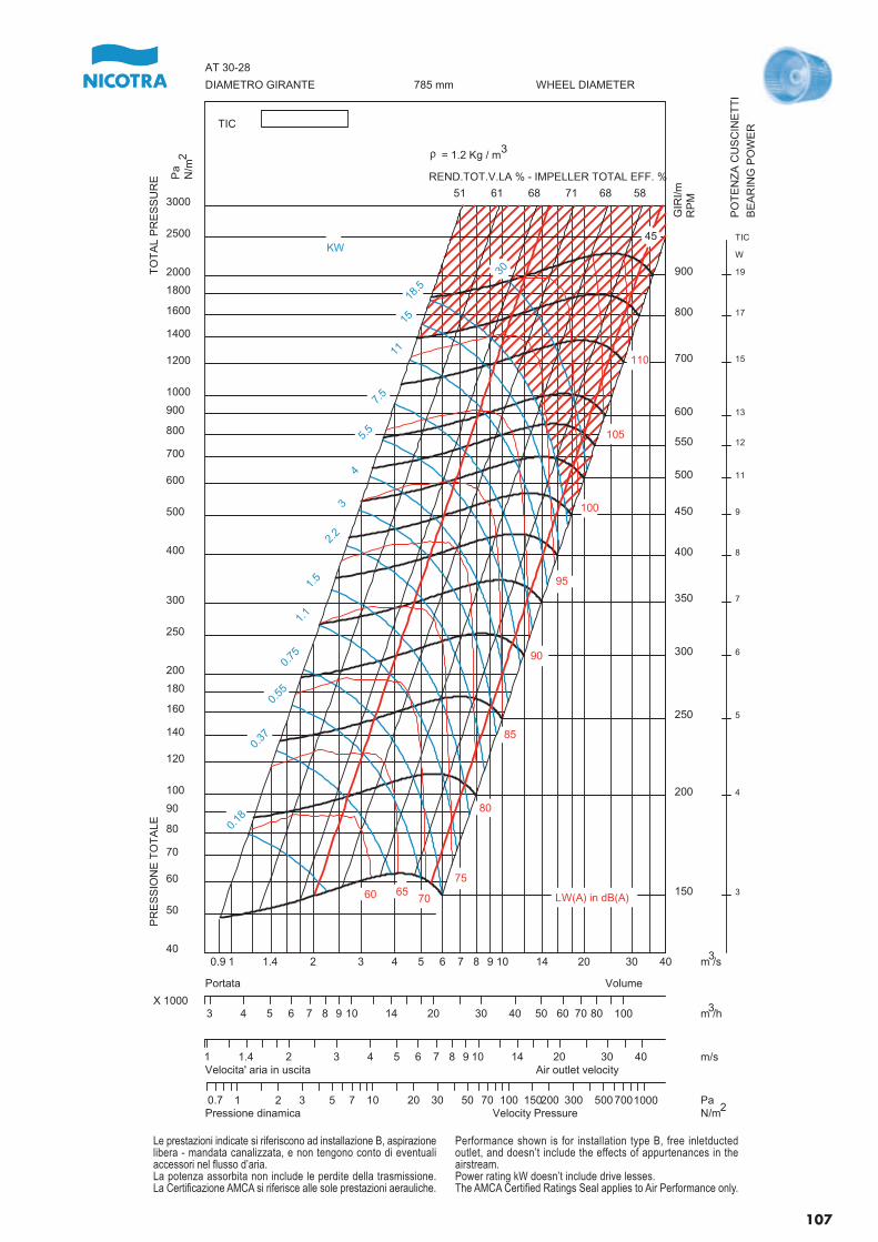
150
200
250
300
350
400
450
500
550
600
700
800
900
3
4
5
6
7
8
9
11
12
13
15
17
19
TIC
W
0.18
0.37
0.55
0.75
1.1
1.5
2.2
3
4
5.5
7.5
11
15
18.5
30
51 61 68 71 68 58
45
60 6570
75
80
85
90
95
100
105
110
0.9 1 1.4 2 3 4 5 6 7 8 9 10 14 20 30 4040
50
60
70
80
90
100
120
140
160
180
200
250
300
400
500
600
700
800
900
1000
1200
1400
1600
1800
2000
2500
3000
PR
ES
SIO
NE
TO
TA
LET
OT
AL
PR
ES
SU
RE
DIAMETRO GIRANTE WHEEL DIAMETER785 mm
AT 30-28
TIC
3 4 5 6 7 8 9 10 14 20 30 40 50 60 70 80 100X 1000
VolumePortata
1 1.4 2 3 4 5 6 7 8 9 10 14 20 30 40Velocita' aria in uscita Air outlet velocity
0.7 1 2 3 5 7 10 20 30 50 70 100 150200 300 5007001000Pressione dinamica Velocity Pressure
KW
m /s
GIR
I/mR
PM
Pa
N/m
REND.TOT.V.LA % - IMPELLER TOTAL EFF. %
m /h
m/s
PaN/m
LW(A) in dB(A)
r = 1.2 Kg / m
PO
TE
NZ
A C
US
CIN
ET
TI
BE
AR
ING
PO
WE
R
3
2
3
3
2
Le prestazioni indicate si riferiscono ad installazione B, aspirazionelibera - mandata canalizzata, e non tengono conto di eventualiaccessori nel flusso d’aria.La potenza assorbita non include le perdite della trasmissione.La Certificazione AMCA si riferisce alle sole prestazioni aerauliche.
Performance shown is for installation type B, free inletductedoutlet, and doesn’t include the effects of appurtenances in theairstream.Power rating kW doesn’t include drive lesses.The AMCA Certified Ratings Seal applies to Air Performance only.
107
APPENDIX
Coefficients for calculation of noiseratingsThe tables below show, for each fansize, the coefficients required to esti-mate sufficiently approximate valuesof those Sound Power Levels whichcannot be directly read on the opera-ting diagrams. These coefficients aregiven on three different similaritycurves and at three different operatingspeeds.Those coefficients marked with “SX”apply to operating points located onthe left border of the normal operatingarea (red diagonal line on the left).The coefficients marked with “DX”apply to operating points located onthe right border of the normal opera-ting area (red diagonal line on theright). Those coefficients marked with“EtaTMax” apply to operating pointslocated on the maximum efficiencyoperating line.It is preferable to interpolate betweenthe listed coefficients when referringto the operating points between thelisted speeds or operating lines.The Ventil selection program appliesthe complete calculation procedure,in accordance with BS 848 Part 2,Appendix G, and provides easily thebest approximation of the results.
APPENDICE
Coefficienti per il calcolo dei livellidi potenza sonoraLe tabelle che seguono elencano, perciascuna grandezza di ventilatore, icoefficienti occorrenti per individuare,in maniera sufficientemente appros-simata, i livelli di potenza sonora nondirettamente rilevabili dai diagrammidi funzionamento, in corrispondenzadi tre differenti curve di similitudine,ed a tre differenti velocità di impiego.I coefficienti contraddistinti con lasigla “SX” si applicano a punti dilavoro sul margine sinistro della zonadi normale funzionamento (linea dia-gonale rossa sinistra). I coefficienticontraddistinti con la sigla “DX” siapplicano a punti di lavoro sul marginedestro della zona di normale funzio-namento (linea diagonale rossa de-stra). I coefficienti contraddistinti conla sigla "EtaTMax" si applicano a puntidi lavoro sulla linea di massima effi-cienza.In punti intermedi tra le velocità o trale linee di similitudine indicate è pre-feribile interpolare tra i coefficientielencati.Il programma di selezione Ventil ap-plica il procedimento di calcolo com-pleto, conforme a BS 848 Parte 2,Appendice G, e garantisce in manieraagevole la migliore approssimazionedei risultati.
108
ANHANG
Koeffizienten für die Berechnungvon LärmwertenAus den nahestehenden Abbildungensind für jede Gebläsegröße die Koef-fizienten ersichtlich, die erforderlichsind, um hinreichend genaue Nähe-rungswerte für den Schalldruckpegelzu ermitteln, die sich nicht direkt amBetriebsdiagramm ablesen lassen,entsprechend dreier Näherungskurvenund dreier Drehzahlen.Die mit “SX” markierten Koeffizientengelten für die Arbeitspunkte am linkenRand des normalen Betriebsbereichs(rote Diagonale auf der linken Seite).Die mit “DX” markierten Koeffizientengelten für Arbeitspunkte am rechtenRand des normalen Betriebsbereichs(rote Diagonale auf der rechten Seite).Die mit “EtaTMax” gekennzeichnetenKoeffizienten gelten für Arbeitspunkte,die in dem Betriebsbereich mit demhöchsten Wirkungsgrad liegen.Sofern Arbeitspunkte zwischenaufgeführten Drehzahlen bzw. Betriebs-bereichen liegen, ist eine entsprechen-de Interpolation zu empfehlen.Das Auswahlprogramm Ventil ver-wendet das vollständige Rechenver-fahren gemäß BS 848, Teil 2, AnhangG und liefert mit Abstand die bestenNäherungswerte.
APPENDICE
Coefficients pour le calcul des ni-veaux de puissance sonoreLes tableaux qui suivent détaillentpour chaque taille de ventilateur, lescoefficients nécessaires pour déter-miner de façon suffisamment préciseles niveaux de puissance sonore quine peuvent être directement relevésdans les courbes de fonctionnementcorrespondant aux trois courbes decomparaison et aux trois vitessesd’utilisation.Les coefficients différenciés par lesigle “SX” s’appliquent à des pointsde fonctionnement sur la marge gau-che de la zone d’utilisation normale(ligne diagonale rouge gauche). Lescoefficients différenciés par le sigle“DX” s’appliquent à des points defonctionnement sur la marge droitede la zone d’utilisation normale (lignediagonale rouge droite). Les coeffi-cients différenciés par le sigle“EtaTMax” s’appliquent à des pointsde fonctionnement sur la ligne duplus fort rendement.Il est préférable d’interpoler entre lescoefficients énumérés dans les pointsintermédiaires entre les vitesses ouentre les lignes de comparaison.Le programme de sélection Ventilapplique le procédé de calcul completconforme à BS 848 Partie 2, Appen-dice G et garantit de manière simpleune meilleure approximation des ré-sultats.
APÉNDICE
Coeficientes para calcular nivelesde ruidoLas tablas siguientes listan, para cadauno de los tamaños de ventilador, loscoeficientes necesarios para identifi-car de manera suficientemente apro-ximada los niveles de potencia sonorano directamente determinables en losdiagramas de funcionamiento, en cor-respondencia de tres diferentes cur-vas de similitud, y a tres diferentesvelocidades de empleo.Los coeficientes distinguidos con lasigla “SX” se aplican a puntos detrabajo en el margen izquierdo de lazona de normal funcionamiento (líneadiagonal roja izquierda). Los coefi-cientes señalados con la sigla “DX”se aplican a puntos de trabajo en elmargen derecho de la zona de normalfuncionamiento (línea diagonal rojaderecha). Los coeficientes señaladoscon la EtaTMax se aplican a puntosde trabajo en la línea de máximo ren-dimiento.En puntos intermedios entre las velo-cidades o entre las líneas de similitudindicadas es preferible interpolar entrelos coeficientes indicados.El programa de selección Ventil aplicael procedimiento de cálculo completo,conforme a BS 848 Parte 2, ApéndiceG, y garantiza de manera fácil la mejoraproximación de los resultados.
109
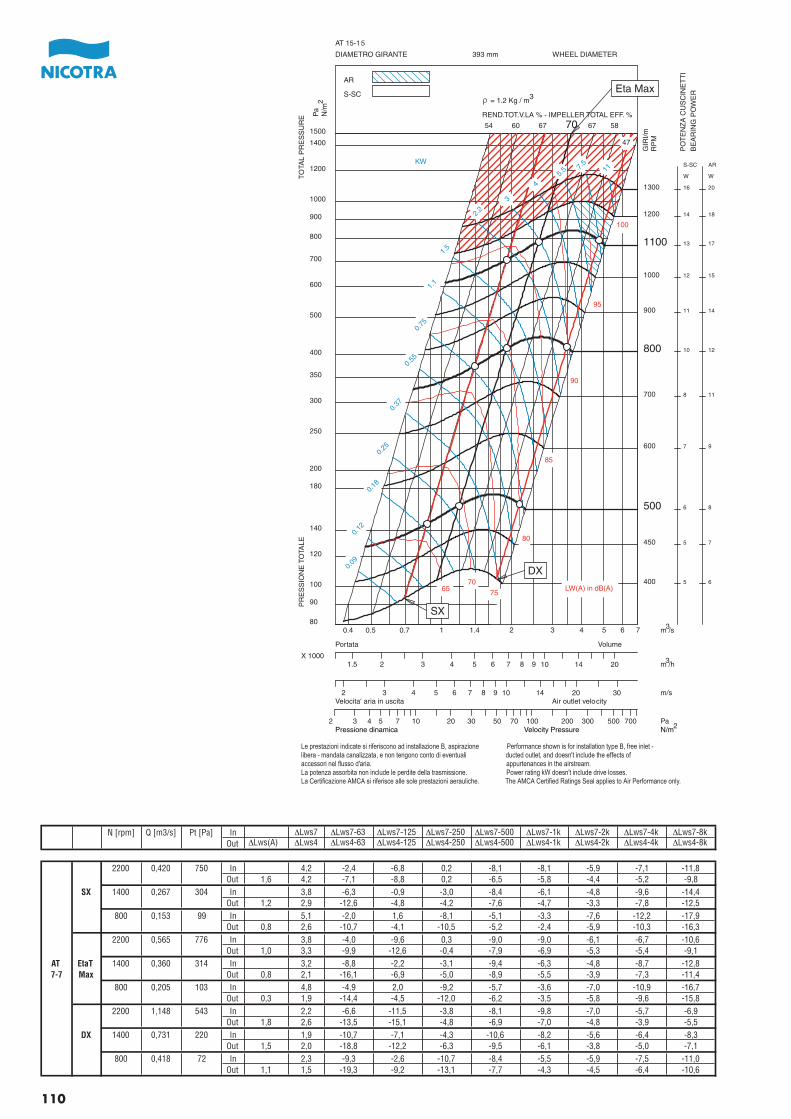
Pressione dinamica Velocity Pressure N/m
110
N [rpm] Q [m3/s] Pt [Pa] In ∆Lws7 ∆Lws7-63 ∆Lws7-125 ∆Lws7-250 ∆Lws7-500 ∆Lws7-1k ∆Lws7-2k ∆Lws7-4k ∆Lws7-8kOut ∆Lws(A) ∆Lws4 ∆Lws4-63 ∆Lws4-125 ∆Lws4-250 ∆Lws4-500 ∆Lws4-1k ∆Lws4-2k ∆Lws4-4k ∆Lws4-8k
2200 0,420 750 In 4,2 -2,4 -6,8 0,2 -8,1 -8,1 -5,9 -7,1 -11,8Out 1,6 4,2 -7,1 -8,8 0,2 -6,5 -5,8 -4,4 -5,2 -9,8
SX 1400 0,267 304 In 3,8 -6,3 -0,9 -3,0 -8,4 -6,1 -4,8 -9,6 -14,4Out 1,2 2,9 -12,6 -4,8 -4,2 -7,6 -4,7 -3,3 -7,8 -12,5
800 0,153 99 In 5,1 -2,0 1,6 -8,1 -5,1 -3,3 -7,6 -12,2 -17,9Out 0,8 2,6 -10,7 -4,1 -10,5 -5,2 -2,4 -5,9 -10,3 -16,3
2200 0,565 776 In 3,8 -4,0 -9,6 0,3 -9,0 -9,0 -6,1 -6,7 -10,6Out 1,0 3,3 -9,9 -12,6 -0,4 -7,9 -6,9 -5,3 -5,4 -9,1
AT EtaT 1400 0,360 314 In 3,2 -8,8 -2,2 -3,1 -9,4 -6,3 -4,8 -8,7 -12,87-7 Max Out 0,8 2,1 -16,1 -6,9 -5,0 -8,9 -5,5 -3,9 -7,3 -11,4
800 0,205 103 In 4,8 -4,9 2,0 -9,2 -5,7 -3,6 -7,0 -10,9 -16,7Out 0,3 1,9 -14,4 -4,5 -12,0 -6,2 -3,5 -5,8 -9,6 -15,8
2200 1,148 543 In 2,2 -6,6 -11,5 -3,8 -8,1 -9,8 -7,0 -5,7 -6,9Out 1,8 2,6 -13,5 -15,1 -4,8 -6,9 -7,0 -4,8 -3,9 -5,5
DX 1400 0,731 220 In 1,9 -10,7 -7,1 -4,3 -10,6 -8,2 -5,6 -6,4 -8,3Out 1,5 2,0 -18,8 -12,2 -6,3 -9,5 -6,1 -3,8 -5,0 -7,1
800 0,418 72 In 2,3 -9,3 -2,6 -10,7 -8,4 -5,5 -5,9 -7,5 -11,0Out 1,1 1,5 -19,3 -9,2 -13,1 -7,7 -4,3 -4,5 -6,4 -10,6
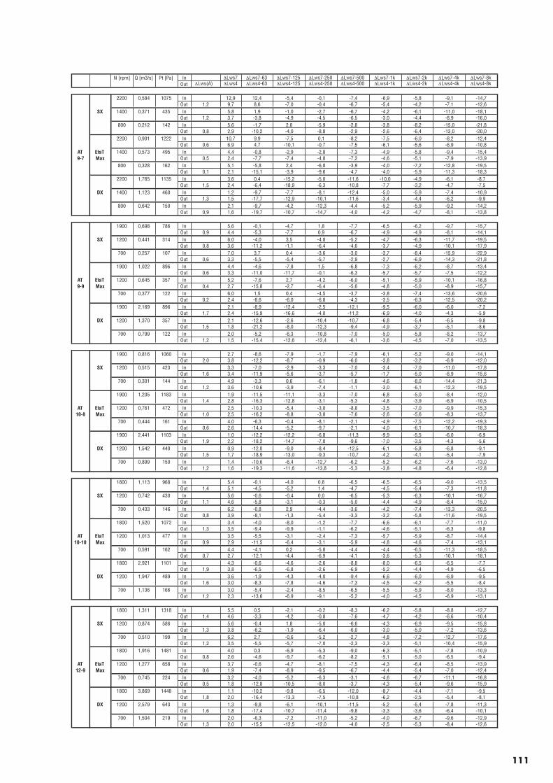
N [rpm] Q [m3/s] Pt [Pa] In ∆Lws7 ∆Lws7-63 ∆Lws7-125 ∆Lws7-250 ∆Lws7-500 ∆Lws7-1k ∆Lws7-2k ∆Lws7-4k ∆Lws7-8kOut ∆Lws(A) ∆Lws4 ∆Lws4-63 ∆Lws4-125 ∆Lws4-250 ∆Lws4-500 ∆Lws4-1k ∆Lws4-2k ∆Lws4-4k ∆Lws4-8k
2200 0,584 1075 In 12,9 12,4 -5,4 -0,1 -7,4 -6,9 -5,8 -9,1 -14,7Out 1,2 9,7 8,6 -7,0 -0,4 -6,7 -5,4 -4,2 -7,1 -12,6
SX 1400 0,371 435 In 5,8 1,9 -1,0 -2,7 -6,7 -4,2 -6,1 -11,0 -18,1Out 1,2 3,7 -3,8 -4,9 -4,5 -6,5 -3,0 -4,4 -8,9 -16,0
800 0,212 142 In 5,6 -1,7 2,0 -5,9 -2,8 -3,8 -8,2 -15,0 -21,8Out 0,8 2,9 -10,2 -4,0 -8,8 -2,9 -2,6 -6,4 -13,0 -20,0
2200 0,901 1222 In 10,7 9,9 -7,5 0,1 -8,2 -7,5 -6,0 -8,2 -12,4Out 0,6 6,9 4,7 -10,1 -0,7 -7,5 -6,1 -5,6 -6,9 -10,8
AT EtaT 1400 0,573 495 In 4,4 -0,8 -2,9 -2,8 -7,3 -4,9 -5,8 -9,4 -15,49-7 Max Out 0,5 2,4 -7,7 -7,4 -4,8 -7,2 -4,6 -5,1 -7,9 -13,9
800 0,328 162 In 5,1 -5,8 2,4 -6,8 -3,9 -4,0 -7,2 -12,8 -19,5Out 0,1 2,1 -15,1 -3,9 -9,6 -4,7 -4,0 -5,9 -11,3 -18,3
2200 1,765 1135 In 3,6 0,4 -15,2 -5,0 -11,6 -10,0 -4,9 -6,1 -8,7Out 1,5 2,4 -6,4 -18,9 -6,3 -10,8 -7,7 -3,2 -4,7 -7,5
DX 1400 1,123 460 In 1,2 -9,7 -7,7 -8,1 -12,4 -5,0 -5,9 -7,4 -10,9Out 1,3 1,5 -17,7 -12,9 -10,1 -11,6 -3,4 -4,4 -6,2 -9,9
800 0,642 150 In 2,1 -9,7 -4,2 -12,3 -4,4 -5,2 -5,9 -9,2 -14,2Out 0,9 1,6 -19,7 -10,7 -14,7 -4,0 -4,2 -4,7 -8,1 -13,8
1900 0,698 786 In 5,6 -0,1 -4,7 1,8 -7,7 -6,5 -6,2 -9,7 -15,7Out 0,9 4,4 -5,3 -7,7 0,9 -6,7 -4,9 -4,9 -8,1 -14,1
SX 1200 0,441 314 In 6,0 -4,0 3,5 -4,8 -5,2 -4,7 -6,3 -11,7 -19,5Out 0,8 3,6 -11,2 -1,1 -6,4 -4,6 -3,7 -4,9 -10,1 -17,9
700 0,257 107 In 7,0 3,7 0,4 -3,6 -3,0 -3,7 -8,4 -15,9 -22,9Out 0,6 3,3 -5,5 -5,4 -5,7 -2,9 -2,7 -6,9 -14,3 -21,8
1900 1,022 896 In 4,4 -4,6 -7,8 1,5 -6,8 -7,3 -6,2 -8,7 -13,4Out 0,6 3,3 -11,0 -11,7 -0,1 -6,3 -5,7 -5,7 -7,5 -12,2
AT EtaT 1200 0,645 357 In 5,2 -7,6 2,7 -4,2 -6,0 -5,1 -5,9 -10,1 -16,89-9 Max Out 0,4 2,7 -15,8 -2,7 -6,4 -5,6 -4,8 -5,0 -8,9 -15,7
700 0,377 122 In 6,0 1,5 0,4 -4,5 -3,7 -3,8 -7,4 -13,6 -20,6Out 0,2 2,4 -8,6 -6,0 -6,8 -4,3 -3,5 -6,3 -12,5 -20,2
1900 2,169 896 In 2,1 -8,9 -12,4 -2,5 -12,1 -9,5 -6,0 -6,0 -7,2Out 1,7 2,4 -15,9 -16,6 -4,0 -11,2 -6,9 -4,0 -4,3 -5,9
DX 1200 1,370 357 In 2,1 -12,6 -2,6 -10,4 -10,7 -6,8 -5,4 -6,5 -9,8Out 1,5 1,8 -21,2 -8,0 -12,3 -9,4 -4,9 -3,7 -5,1 -8,6
700 0,799 122 In 2,0 -5,2 -6,3 -10,8 -7,0 -5,0 -5,8 -8,2 -13,7Out 1,2 1,5 -15,4 -12,6 -12,4 -6,1 -3,6 -4,5 -7,0 -13,5
1900 0,816 1060 In 2,7 -8,6 -7,9 -1,7 -7,9 -6,1 -5,2 -9,0 -14,1Out 2,0 3,8 -12,2 -8,7 -0,9 -6,0 -3,8 -3,2 -6,9 -12,0
SX 1200 0,515 423 In 3,3 -7,0 -2,9 -3,3 -7,0 -3,4 -7,0 -11,0 -17,8Out 1,6 3,4 -11,9 -5,6 -3,7 -5,7 -1,7 -5,0 -8,9 -15,6
700 0,301 144 In 4,9 -3,3 0,6 -6,1 -1,8 -4,6 -8,0 -14,4 -21,3Out 1,2 3,6 -10,6 -3,9 -7,4 -1,1 -3,0 -6,1 -12,3 -19,5
1900 1,205 1183 In 1,9 -11,5 -11,1 -3,3 -7,0 -6,8 -5,0 -8,4 -12,0Out 1,4 2,8 -16,3 -12,8 -3,1 -5,3 -4,8 -3,9 -6,9 -10,5
AT EtaT 1200 0,761 472 In 2,5 -10,3 -5,4 -3,0 -8,8 -3,5 -7,0 -9,9 -15,310-8 Max Out 1,0 2,5 -16,2 -8,8 -3,8 -7,6 -2,6 -5,6 -8,3 -13,7
700 0,444 161 In 4,0 -6,3 -0,4 -8,1 -2,1 -4,9 -7,5 -12,2 -19,3Out 0,6 2,6 -14,4 -5,2 -9,7 -2,1 -4,0 -6,1 -10,7 -18,3
1900 2,441 1103 In 1,0 -12,2 -12,2 -6,8 -11,3 -9,9 -5,5 -6,0 -6,9Out 1,9 2,2 -18,2 -14,7 -7,0 -9,6 -7,0 -3,5 -4,3 -5,6
DX 1200 1,542 440 In 0,9 -12,0 -9,0 -8,4 -12,5 -6,1 -5,8 -6,8 -9,1Out 1,5 1,7 -18,9 -13,0 -9,3 -10,7 -4,2 -4,1 -5,4 -7,9
700 0,899 150 In 1,4 -10,6 -6,4 -12,7 -6,2 -5,2 -6,2 -7,6 -13,0Out 1,2 1,6 -19,3 -11,6 -13,8 -5,3 -3,8 -4,8 -6,4 -12,8
1800 1,113 968 In 5,4 -0,1 -4,0 0,8 -6,5 -6,5 -6,5 -9,0 -13,5Out 1,4 5,1 -4,5 -5,2 1,4 -4,7 -4,5 -5,4 -7,3 -11,8
SX 1200 0,742 430 In 5,6 -0,6 -0,4 0,0 -6,5 -5,3 -6,3 -10,1 -16,7Out 1,1 4,6 -5,8 -3,1 -0,3 -5,0 -4,4 -4,9 -8,4 -15,0
700 0,433 146 In 6,2 -0,8 2,9 -4,4 -3,6 -4,2 -7,4 -13,3 -20,5Out 0,8 3,9 -8,1 -1,3 -5,4 -3,3 -3,2 -5,8 -11,6 -19,5
1800 1,520 1072 In 3,4 -4,0 -8,0 -1,2 -7,7 -6,6 -6,1 -7,7 -11,0Out 1,3 3,5 -9,4 -9,9 -1,1 -6,2 -4,6 -5,1 -6,3 -9,8
AT EtaT 1200 1,013 477 In 3,5 -5,5 -3,1 -2,4 -7,3 -5,7 -5,9 -8,7 -14,410-10 Max Out 0,9 2,9 -11,5 -6,4 -3,1 -5,9 -4,8 -4,6 -7,4 -13,1
700 0,591 162 In 4,4 -4,1 0,2 -5,8 -4,4 -4,4 -6,5 -11,3 -18,5Out 0,7 2,7 -12,1 -4,4 -6,9 -4,1 -3,6 -5,3 -10,1 -18,1
1800 2,921 1101 In 4,3 -0,6 -4,6 -2,6 -8,8 -8,0 -6,5 -6,5 -7,7Out 1,9 3,8 -6,5 -6,8 -2,6 -6,9 -5,2 -4,4 -4,9 -6,5
DX 1200 1,947 489 In 3,6 -1,9 -4,3 -4,0 -9,4 -6,6 -6,0 -6,9 -9,5Out 1,6 3,0 -8,3 -7,8 -4,6 -7,3 -4,5 -4,2 -5,5 -8,4
700 1,136 166 In 3,0 -5,4 -2,4 -8,5 -6,5 -5,5 -5,9 -8,0 -13,3Out 1,2 2,3 -13,6 -6,9 -9,1 -5,2 -4,0 -4,5 -6,9 -13,1
1800 1,311 1318 In 5,5 0,5 -2,1 -0,2 -8,3 -6,2 -5,8 -8,8 -12,7Out 1,4 4,6 -3,3 -4,2 -0,8 -7,6 -4,7 -4,2 -6,6 -10,4
SX 1200 0,874 586 In 5,6 -0,4 1,8 -5,0 -6,6 -4,3 -6,9 -9,5 -15,8Out 1,3 3,8 -6,2 -1,9 -6,4 -6,0 -3,0 -5,0 -7,2 -13,6
700 0,510 199 In 6,2 2,7 -0,6 -5,2 -2,7 -4,8 -7,2 -12,7 -17,6Out 1,2 3,5 -5,5 -5,7 -7,0 -2,3 -3,3 -5,1 -10,4 -15,9
1800 1,916 1481 In 4,0 0,3 -6,9 -5,3 -9,0 -6,3 -5,1 -7,8 -10,9Out 0,8 2,6 -4,6 -9,7 -6,2 -8,2 -5,1 -5,0 -6,5 -9,4
AT EtaT 1200 1,277 658 In 3,7 -0,6 -4,7 -8,1 -7,5 -4,3 -6,4 -8,5 -13,912-9 Max Out 0,6 1,9 -7,4 -8,9 -9,5 -6,7 -4,4 -5,4 -7,0 -12,4
700 0,745 224 In 3,2 -4,0 -5,2 -6,3 -3,1 -4,6 -6,7 -11,1 -16,8Out 0,5 1,8 -12,8 -10,5 -8,0 -3,7 -4,3 -5,4 -9,6 -15,9
1800 3,869 1448 In 1,1 -10,2 -9,8 -6,5 -12,0 -8,7 -4,4 -7,1 -9,5Out 1,8 2,0 -16,4 -13,3 -7,5 -10,8 -6,2 -2,5 -5,4 -8,1
DX 1200 2,579 643 In 1,3 -9,8 -6,1 -10,1 -11,5 -5,2 -5,4 -7,8 -11,3Out 1,6 1,8 -17,4 -10,7 -11,4 -9,8 -3,3 -3,6 -6,4 -10,1
700 1,504 219 In 2,0 -6,3 -7,2 -11,0 -5,2 -4,0 -6,7 -9,6 -12,9Out 1,3 2,0 -15,5 -12,5 -12,0 -4,0 -2,5 -5,3 -8,4 -12,6
111
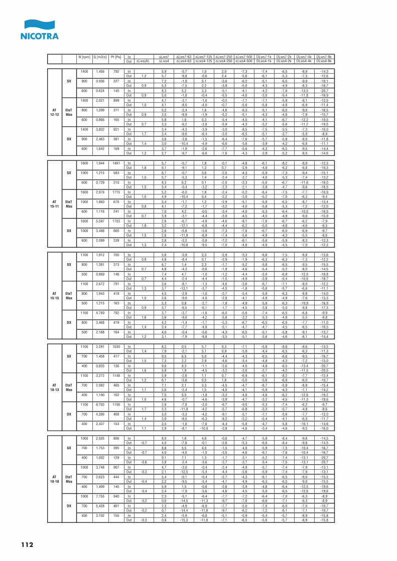
N [rpm] Q [m3/s] Pt [Pa] In ∆Lws7 ∆Lws7-63 ∆Lws7-125 ∆Lws7-250 ∆Lws7-500 DLws7-1k DLws7-2k DLws7-4k DLws7-8kOut ∆Lws(A) ∆Lws4 ∆Lws4-63 ∆Lws4-125 ∆Lws4-250 ∆Lws4-500 DLws4-1k DLws4-2k DLws4-4k DLws4-8k
1400 1,456 792 In 5,9 -5,7 1,0 2,0 -7,3 -7,4 -6,5 -8,9 -14,3Out 1,2 5,7 -9,8 -0,6 2,4 -5,6 -6,1 -5,3 -7,3 -12,6
SX 900 0,936 327 In 7,2 -1,9 5,1 -3,6 -6,2 -5,1 -6,5 -9,9 -18,1Out 0,9 5,3 -7,5 2,2 -3,8 -5,0 -4,3 -4,9 -8,3 -16,7
600 0,624 145 In 8,3 5,2 3,3 -5,1 -4,1 -4,2 -7,0 -13,5 -20,7Out 0,9 5,0 -1,8 -0,4 -5,5 -4,0 -3,0 -5,4 -11,8 -19,9
1400 2,021 899 In 4,7 -3,1 -1,6 -0,5 -7,1 -7,1 -5,9 -8,1 -12,5Out 1,0 4,1 -8,0 -4,0 -0,7 -5,6 -5,8 -4,8 -6,9 -11,4
AT EtaT 900 1,299 371 In 5,2 -2,4 1,6 -4,6 -6,3 -5,1 -6,0 -9,0 -16,512-12 Max Out 0,9 3,5 -8,9 -1,9 -5,2 -5,1 -4,3 -4,8 -7,9 -15,7
600 0,866 165 In 5,8 1,6 0,3 -5,4 -4,5 -4,1 -6,7 -12,2 -19,5Out 0,7 3,3 -6,2 -3,8 -5,9 -4,3 -3,2 -5,6 -11,2 -19,5
1400 3,832 921 In 3,4 -4,3 -3,9 -3,0 -8,5 -7,5 -5,5 -7,3 -10,0Out 1,7 3,4 -9,6 -6,4 -3,0 -6,5 -5,1 -3,7 -5,8 -8,9
DX 900 2,463 381 In 3,6 -3,8 -1,5 -6,4 -7,6 -5,7 -5,8 -8,0 -11,8Out 1,4 3,0 -10,4 -4,9 -6,6 -5,6 -3,9 -4,2 -6,8 -11,1
600 1,642 169 In 3,7 -1,9 -2,6 -7,7 -5,6 -4,3 -6,5 -9,5 -14,4Out 1,2 2,7 -9,7 -6,6 -7,6 -4,3 -2,9 -5,2 -8,5 -14,6
1600 1,944 1491 In 5,7 -5,7 1,8 -0,1 -4,8 -6,1 -8,2 -8,9 -12,3Out 1,8 6,1 -9,1 1,3 0,7 -2,9 -4,0 -6,2 -6,8 -10,3
SX 1000 1,215 583 In 6,7 -0,7 3,6 -2,5 -4,3 -5,9 -7,3 -9,4 -15,1Out 1,5 5,7 -5,3 1,4 -2,4 -2,7 -4,0 -5,3 -7,4 -13,2
600 0,729 210 In 8,3 6,2 0,1 -2,0 -3,3 -5,6 -6,7 -11,6 -18,0Out 1,5 5,4 -0,4 -3,2 -2,3 -2,1 -3,8 -4,7 -9,6 -16,5
1600 2,976 1715 In 5,2 -6,0 1,8 -2,4 -5,2 -6,4 -7,5 -7,7 -10,9Out 1,0 4,9 -10,4 0,4 -2,2 -3,8 -5,2 -7,0 -6,3 -9,4
AT EtaT 1000 1,860 670 In 5,4 -1,7 1,2 -2,9 -5,1 -5,9 -6,5 -8,7 -13,415-11 Max Out 0,8 4,1 -7,2 -1,7 -3,2 -4,0 -5,8 -5,3 -7,2 -12,0
600 1,116 241 In 7,0 4,2 -0,5 -3,4 -4,0 -5,3 -6,4 -10,5 -16,5Out 0,7 3,9 -3,1 -4,4 -3,9 -4,5 -4,5 -4,9 -9,0 -15,9
1600 5,597 1703 In 2,6 -6,7 -4,8 -4,6 -8,1 -7,6 -6,7 -6,2 -7,9Out 1,8 3,2 -12,1 -6,8 -4,4 -6,2 -5,0 -4,8 -4,6 -6,5
DX 1000 3,498 665 In 2,6 -5,8 -3,8 -7,3 -7,8 -6,7 -6,0 -6,9 -9,7Out 1,5 2,6 -11,9 -6,9 -7,4 -5,6 -4,9 -4,3 -5,5 -8,6
600 2,099 239 In 2,8 -3,2 -5,8 -7,2 -6,1 -5,6 -5,9 -8,3 -12,3Out 1,3 2,4 -10,8 -9,5 -7,0 -4,8 -4,0 -4,5 -7,0 -12,3
1100 1,912 705 In 5,6 -3,9 2,3 -2,9 -3,3 -6,6 -7,5 -8,8 -13,6Out 0,9 4,8 -8,4 0,1 -2,9 -1,9 -6,3 -6,3 -7,3 -12,2
SX 800 1,391 373 In 6,7 1,4 2,3 -1,7 -5,2 -5,8 -6,5 -9,5 -15,5Out 0,7 4,8 -4,3 -0,6 -1,9 -4,6 -5,4 -5,2 -8,0 -14,5
500 0,869 146 In 7,4 4,7 -1,0 -1,2 -4,4 -5,0 -6,8 -12,0 -18,8Out 0,7 4,4 -2,4 -4,4 -1,5 -4,9 -3,9 -5,4 -10,6 -18,7
1100 2,672 791 In 3,6 -8,1 -1,3 -4,6 -3,6 -6,7 -7,1 -8,0 -12,2Out 1,3 3,7 -13,1 -3,7 -4,5 -1,8 -5,6 -5,7 -6,6 -11,1
AT EtaT 800 1,943 418 In 4,5 -2,9 -1,0 -2,7 -5,4 -5,9 -6,3 -8,8 -14,015-15 Max Out 1,0 3,6 -9,0 -4,0 -2,8 -4,1 -4,9 -4,9 -7,6 -13,3
500 1,215 163 In 5,3 0,8 -2,7 -1,8 -4,9 -5,0 -6,3 -10,9 -16,9Out 0,9 3,7 -6,5 -6,1 -1,7 -4,5 -3,8 -5,0 -9,8 -17,3
1100 4,769 792 In 3,7 -3,7 -1,6 -6,0 -5,6 -7,4 -6,5 -6,8 -9,9Out 1,6 3,6 -9,0 -4,2 -5,8 -3,2 -5,3 -4,8 -5,5 -8,8
DX 800 3,468 419 In 4,2 -1,4 -1,7 -5,3 -6,7 -6,5 -6,0 -7,7 -11,0Out 1,4 3,4 -7,7 -4,8 -5,1 -4,7 -4,7 -4,5 -6,5 -10,5
500 2,168 164 In 4,0 -0,4 -5,6 -4,3 -6,5 -5,1 -5,8 -9,1 -13,7Out 1,2 3,1 -7,9 -8,8 -3,5 -5,1 -3,6 -4,6 -8,1 -14,4
1100 2,291 1030 In 8,2 0,5 5,7 0,3 -7,1 -5,8 -8,6 -8,6 -13,5Out 1,4 7,9 -2,1 5,1 0,9 -5,9 -4,4 -6,5 -6,3 -11,3
SX 700 1,458 417 In 9,5 6,5 5,0 -4,4 -4,3 -6,5 -6,6 -9,5 -16,7Out 1,5 7,3 2,2 2,9 -4,6 -3,4 -4,8 -4,3 -7,2 -15,0
400 0,833 136 In 9,6 8,3 -1,1 -2,6 -4,0 -4,8 -6,5 -13,4 -20,7Out 1,6 5,9 1,9 -4,5 -3,2 -3,0 -2,7 -4,2 -11,5 -20,5
1100 3,272 1148 In 5,9 -2,6 1,1 0,7 -6,9 -6,1 -8,2 -7,7 -12,4Out 1,2 6,1 -5,6 0,5 1,8 -5,0 -5,6 -6,8 -6,0 -10,7
AT EtaT 700 2,082 465 In 7,1 2,1 3,3 -4,5 -4,7 -6,7 -5,9 -8,8 -15,418-13 Max Out 1,1 5,6 -2,4 1,5 -4,0 -4,1 -5,9 -4,3 -7,1 -14,2
400 1,190 152 In 7,5 5,5 -1,9 -3,3 -4,8 -4,6 -6,2 -12,6 -19,2Out 1,0 4,6 -0,7 -4,6 -3,9 -4,7 -3,2 -4,5 -11,3 -19,6
1100 6,703 1156 In 2,6 -7,8 -3,0 -6,7 -9,5 -5,3 -7,4 -6,2 -9,7Out 1,7 3,3 -11,9 -4,2 -5,7 -6,8 -3,3 -5,7 -4,8 -8,6
DX 700 4,266 468 In 3,0 -3,3 -4,2 -9,1 -5,1 -7,1 -5,6 -7,7 -12,0Out 1,4 3,0 -8,5 -6,3 -8,2 -3,2 -5,4 -4,1 -6,5 -11,7
400 2,437 153 In 3,5 -1,6 -7,6 -4,4 -5,8 -4,7 -5,8 -10,1 -14,6Out 1,1 2,9 -8,1 -10,0 -3,8 -4,6 -3,4 -4,6 -9,5 -16,0
1000 2,505 806 In 8,0 1,6 4,8 -0,6 -4,7 -5,8 -8,4 -9,8 -14,5Out -0,7 4,0 -7,8 -0,1 -2,6 -5,3 -6,0 -8,4 -9,8 -14,5
SX 700 1,753 395 In 8,8 5,5 4,0 -1,5 -4,0 -5,9 -7,5 -10,4 -16,7Out -0,7 4,0 -4,0 -1,0 -3,5 -4,6 -6,1 -7,6 -10,4 -16,7
400 1,002 129 In 9,1 7,1 1,3 -1,7 -3,1 -5,2 -7,4 -13,1 -20,7Out -0,6 3,8 -2,4 -3,6 -3,7 -3,7 -5,4 -7,5 -13,1 -20,7
1000 3,748 907 In 4,7 -3,0 -0,4 -2,4 -4,9 -5,7 -7,4 -7,9 -13,1Out -0,3 2,1 -12,5 -5,4 -4,4 -5,6 -5,9 -7,4 -7,9 -13,1
AT EtaT 700 2,623 444 In 5,4 -0,1 -0,4 -2,7 -4,3 -6,1 -6,5 -9,0 -15,518-18 Max Out -0,4 2,2 -9,5 -5,4 -4,7 -4,9 -6,3 -6,5 -9,0 -15,5
400 1,499 145 In 5,9 1,5 -0,6 -2,6 -3,9 -4,8 -6,4 -12,5 -19,6Out -0,4 2,4 -7,9 -5,6 -4,6 -4,5 -5,0 -6,5 -12,6 -19,6
1000 7,755 940 In 2,3 -5,1 -6,4 -7,7 -7,2 -6,4 -7,0 -6,3 -8,9Out -0,2 0,6 -14,5 -11,3 -9,7 -7,8 -6,6 -7,1 -6,3 -8,9
DX 700 5,428 461 In 2,3 -4,9 -6,9 -7,7 -5,6 -7,0 -6,0 -7,0 -10,7Out -0,2 0,7 -14,4 -11,8 -9,7 -6,2 -7,2 -6,1 -7,1 -10,7
400 3,102 150 In 2,4 -5,9 -6,8 -5,1 -5,9 -5,4 -5,7 -8,9 -15,8Out -0,3 0,8 -15,3 -11,8 -7,1 -6,5 -5,6 -5,7 -8,9 -15,8
112
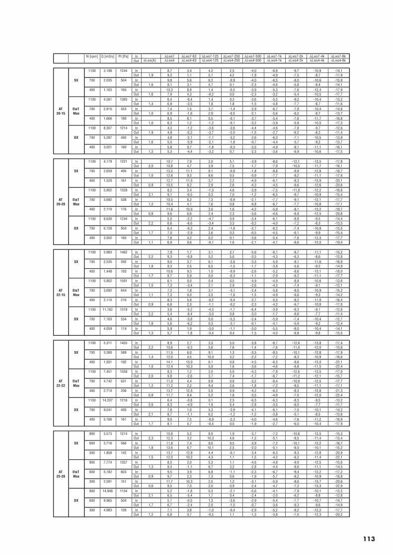
N [rpm] Q [m3/s] Pt [Pa] In ∆Lws7 ∆Lws7-63 ∆Lws7-125 ∆Lws7-250 ∆Lws7-500 ∆Lws7-1k ∆Lws7-2k ∆Lws7-4k ∆Lws7-8kOut ∆Lws(A) ∆Lws4 ∆Lws4-63 ∆Lws4-125 ∆Lws4-250 ∆Lws4-500 ∆Lws4-1k ∆Lws4-2k ∆Lws4-4k ∆Lws4-8k
1100 3,198 1244 In 8,7 3,4 4,2 2,5 -4,0 -6,8 -9,7 -10,9 -14,1Out 1,9 9,3 1,1 5,1 4,2 -1,9 -4,9 -7,5 -8,7 -11,9
SX 700 2,035 504 In 9,8 5,6 6,2 -0,9 -4,0 -6,5 -8,0 -10,6 -15,9Out 1,6 9,1 3,1 5,7 0,1 -2,3 -4,6 -5,8 -8,4 -14,1
400 1,163 165 In 10,3 8,8 1,4 -0,5 -3,9 -5,3 -7,6 -12,4 -17,9Out 1,6 7,9 4,3 -0,2 0,0 -2,3 -3,2 -5,4 -10,5 -17,7
1100 4,581 1365 In 6,4 -0,4 1,4 0,3 -3,6 -5,5 -9,2 -10,4 -13,2Out 1,4 6,9 -3,5 1,8 1,8 -1,5 -4,8 -7,7 -8,7 -11,6
AT EtaT 700 2,915 553 In 7,4 1,5 3,7 -1,4 -2,9 -6,7 -7,9 -10,4 -14,820-15 Max Out 1,0 6,9 -1,6 2,9 -0,5 -2,1 -5,6 -6,2 -8,7 -13,7
400 1,666 180 In 8,5 6,1 0,5 -0,1 -3,7 -5,4 -7,6 -11,7 -16,8Out 1,0 6,3 1,2 -1,2 -0,1 -3,2 -3,9 -5,9 -10,5 -17,3
1100 8,307 1214 In 4,3 -1,2 -3,6 -3,6 -4,4 -4,6 -7,8 -9,7 -12,6Out 1,9 4,9 -5,3 -3,7 -2,0 -1,5 -2,7 -6,2 -8,3 -11,4
DX 700 5,287 492 In 4,8 -2,1 -1,1 -3,2 -2,6 -6,0 -7,1 -10,5 -13,9Out 1,6 5,0 -5,9 -2,1 -1,8 -0,7 -4,4 -5,7 -9,3 -13,7
400 3,021 160 In 5,8 0,7 -1,8 -0,3 -3,5 -4,9 -8,1 -11,1 -16,1Out 1,2 5,3 -4,4 -3,2 0,7 -2,3 -3,6 -6,9 -10,6 -17,5
1100 4,179 1221 In 10,7 7,9 2,0 5,1 -3,9 -8,6 -12,1 -13,5 -17,8Out 2,0 10,8 4,7 3,9 7,5 -1,7 -7,9 -10,5 -11,7 -16,1
SX 700 2,659 495 In 13,2 11,1 8,1 -0,9 -1,8 -8,8 -9,9 -12,8 -18,7Out 1,0 12,6 9,3 8,6 0,5 -0,9 -7,7 -8,2 -11,1 -17,6
400 1,520 161 In 12,7 11,5 3,7 2,2 -4,9 -6,1 -8,3 -13,9 -20,1Out 0,9 10,5 8,2 2,9 2,6 -4,3 -4,5 -6,6 -12,6 -20,6
1100 5,802 1328 In 8,2 3,4 -1,3 4,6 -3,9 -7,5 -11,0 -12,2 -16,6Out 2,1 9,1 -0,5 0,3 7,0 -1,2 -6,5 -9,7 -10,9 -15,4
AT EtaT 700 3,692 538 In 10,5 6,2 7,3 -0,9 -2,1 -7,7 -9,1 -12,1 -17,720-20 Max Out 1,2 10,4 4,1 7,6 0,8 -0,8 -6,7 -7,7 -10,8 -17,1
400 2,110 176 In 11,6 10,0 3,0 1,6 -4,2 -5,9 -8,1 -13,2 -19,7Out 0,8 9,6 6,6 2,4 2,3 -3,6 -4,6 -6,9 -12,5 -20,8
1100 9,630 1244 In 5,0 -2,2 -4,7 0,9 -3,4 -6,1 -8,8 -9,5 -14,4Out 2,2 6,6 -6,6 -3,4 3,3 -0,2 -4,0 -7,2 -8,3 -13,5
DX 700 6,128 504 In 6,4 -0,3 2,4 -1,8 -2,7 -6,2 -7,4 -10,9 -15,5Out 1,7 7,0 -2,9 2,6 0,3 -0,5 -4,5 -6,1 -9,9 -15,4
400 3,502 165 In 7,6 4,2 0,2 0,1 -3,6 -5,4 -7,6 -12,3 -17,7Out 1,1 6,9 0,6 -0,1 1,6 -2,1 -4,1 -6,6 -12,0 -19,4
1100 3,983 1462 In 7,9 1,7 3,1 2,7 -5,6 -6,1 -8,7 -11,1 -15,2Out 2,2 9,3 -0,8 5,2 5,0 -3,5 -4,3 -6,3 -8,6 -12,8
SX 700 2,535 592 In 9,0 3,7 6,1 -2,8 -3,3 -5,9 -8,1 -11,6 -16,9Out 1,8 9,3 2,5 6,5 -1,5 -1,7 -3,8 -5,6 -9,2 -14,9
400 1,448 193 In 10,6 9,3 1,0 -0,9 -2,6 -5,2 -8,6 -13,1 -18,0Out 1,7 8,7 5,9 0,0 -0,3 -1,1 -2,9 -6,2 -11,1 -17,7
1100 5,802 1591 In 6,1 0,0 0,4 0,5 -4,9 -4,9 -8,8 -10,6 -13,6Out 1,5 7,3 -3,4 2,1 2,9 -2,6 -4,3 -7,4 -9,1 -12,1
AT EtaT 700 3,692 644 In 7,2 1,8 3,1 -3,1 -2,4 -5,8 -8,0 -10,9 -15,222-15 Max Out 1,1 7,3 0,0 3,5 -1,6 -1,5 -4,9 -6,6 -9,3 -14,2
400 2,110 210 In 8,3 5,8 -0,2 -0,4 -2,7 -5,5 -8,2 -11,9 -16,4Out 0,9 6,8 2,3 -1,1 -0,2 -2,3 -4,2 -6,7 -10,8 -17,0
1100 11,162 1319 In 3,6 -5,2 -4,3 -1,7 -6,4 -3,9 -8,3 -9,1 -12,6Out 2,2 5,4 -9,4 -3,0 0,8 -3,0 -1,7 -6,6 -7,7 -11,4
DX 700 7,103 534 In 4,6 -3,8 0,0 -5,3 -2,4 -5,9 -7,4 -10,4 -12,7Out 1,8 5,6 -6,2 0,3 -3,1 -0,1 -4,1 -5,9 -9,2 -12,4
400 4,059 174 In 5,9 1,9 -3,0 -1,1 -3,0 -5,5 -8,0 -10,4 -14,1Out 1,3 5,7 -1,8 -3,4 0,4 -1,5 -4,0 -6,8 -9,8 -15,5
1100 5,311 1455 In 8,9 2,7 3,3 5,0 -3,8 -8,7 -12,6 -13,8 -17,4Out 2,2 10,6 -0,3 5,6 7,6 -1,4 -7,6 -11,0 -12,0 -15,6
SX 700 3,380 589 In 11,5 6,0 9,1 1,3 -3,5 -8,5 -10,1 -12,8 -17,9Out 1,4 12,0 4,5 10,0 3,2 -2,2 -7,2 -8,3 -10,9 -16,6
400 1,931 192 In 14,1 13,0 6,1 0,8 -4,5 -6,3 -8,6 -13,0 -22,1Out 1,0 12,4 10,3 5,9 1,6 -3,6 -4,6 -6,8 -11,5 -22,4
1100 7,451 1558 In 8,3 1,2 2,0 5,0 -4,3 -7,8 -12,6 -13,5 -17,0Out 2,0 9,8 -2,6 3,7 7,4 -1,7 -6,7 -11,2 -12,1 -15,7
AT EtaT 700 4,742 631 In 11,0 4,4 8,9 0,8 -3,2 -8,4 -10,0 -12,5 -17,722-22 Max Out 1,2 11,2 2,2 9,4 2,6 -1,8 -7,2 -8,5 -11,1 -17,1
400 2,710 206 In 13,7 12,5 5,5 0,9 -4,2 -6,3 -8,3 -12,8 -21,3Out 0,8 11,7 9,4 5,2 1,8 -3,5 -4,9 -7,0 -12,0 -22,4
1100 14,207 1216 In 6,4 -0,8 0,1 2,5 -6,5 -6,3 -8,3 -9,5 -13,2Out 2,6 8,3 -4,9 1,9 5,4 -2,8 -3,5 -6,0 -7,7 -11,7
DX 700 9,041 493 In 7,8 1,0 5,3 -3,9 -4,1 -6,1 -7,0 -10,1 -14,2Out 2,1 8,7 -1,1 6,2 -1,2 -1,2 -3,8 -5,1 -8,5 -13,6
400 5,166 161 In 9,0 7,5 -0,9 -2,3 -4,0 -4,6 -7,6 -11,2 -16,9Out 1,7 8,1 4,7 -0,4 0,0 -1,9 -2,7 -6,0 -10,4 -17,9
900 5,573 1274 In 10,8 5,2 8,0 1,9 -3,7 -7,2 -10,6 -13,5 -15,3Out 2,3 12,3 3,2 10,3 4,6 -1,3 -5,1 -8,5 -11,4 -13,4
SX 600 3,716 566 In 11,8 7,4 9,0 0,5 -3,9 -7,2 -10,1 -12,2 -16,7Out 1,8 12,6 6,7 10,1 2,5 -2,0 -5,1 -8,0 -10,1 -15,2
300 1,858 142 In 13,7 12,8 4,4 -0,1 -3,4 -6,3 -8,3 -12,8 -20,9Out 1,5 12,0 10,2 4,3 1,1 -1,5 -4,2 -6,2 -11,4 -22,1
900 7,774 1357 In 8,5 2,0 5,3 1,1 -4,6 -4,8 -9,9 -12,5 -15,6Out 1,3 9,4 -1,1 6,7 3,2 -2,8 -4,4 -8,6 -11,1 -14,5
AT EtaT 600 5,182 603 In 9,5 3,9 6,8 -1,1 -2,3 -6,7 -9,4 -12,2 -17,225-20 Max Out 0,9 9,7 2,3 7,3 0,6 -1,9 -5,7 -8,2 -10,9 -16,8
300 2,591 151 In 11,7 10,3 2,5 1,2 -3,1 -5,9 -8,6 -13,7 -20,6Out 0,6 9,5 7,0 2,0 0,9 -2,4 -4,7 -7,3 -13,3 -22,9
900 14,948 1134 In 5,2 -1,8 0,3 -2,1 -5,6 -4,1 -7,9 -10,1 -13,5Out 2,1 6,5 -5,4 1,7 0,4 -2,4 -2,0 -6,2 -8,8 -12,8
DX 600 9,965 504 In 5,7 -0,5 1,3 -3,6 -2,9 -5,4 -7,7 -10,7 -14,7Out 1,7 6,7 -2,4 2,0 -1,0 -0,7 -3,6 -6,3 -9,6 -14,9
300 4,983 126 In 7,1 3,8 -1,0 -0,4 -2,9 -5,2 -8,2 -12,2 -17,7Out 1,2 6,8 0,7 -0,5 1,1 -1,3 -3,8 -7,0 -12,3 -20,2
113
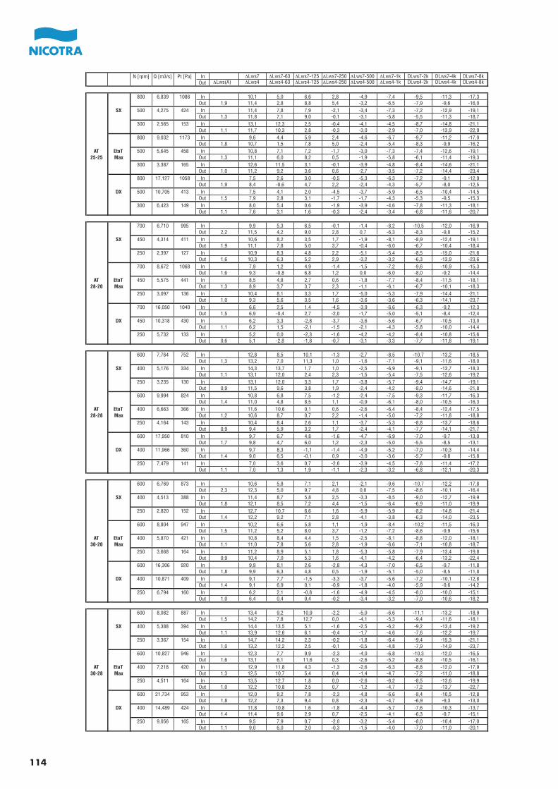
N [rpm] Q [m3/s] Pt [Pa] In ∆Lws7 ∆Lws7-63 ∆Lws7-125 ∆Lws7-250 ∆Lws7-500 ∆Lws7-1k DLws7-2k DLws7-4k DLws7-8kOut ∆Lws(A) ∆Lws4 ∆Lws4-63 ∆Lws4-125 ∆Lws4-250 ∆Lws4-500 ∆Lws4-1k DLws4-2k DLws4-4k DLws4-8k
800 6,839 1086 In 10,1 5,0 6,6 2,8 -4,9 -7,4 -9,5 -11,3 -17,3Out 1,9 11,4 2,8 8,8 5,4 -3,2 -6,5 -7,9 -9,6 -16,0
SX 500 4,275 424 In 11,4 7,8 7,9 -2,1 -3,4 -7,3 -7,2 -12,9 -19,1Out 1,3 11,8 7,1 9,0 -0,1 -3,1 -5,8 -5,5 -11,3 -18,7
300 2,565 153 In 13,1 12,3 2,5 -0,4 -4,1 -4,5 -8,7 -14,8 -21,1Out 1,1 11,7 10,3 2,8 -0,3 -3,0 -2,9 -7,0 -13,9 -22,9
800 9,032 1173 In 9,6 4,4 5,9 2,4 -4,6 -6,7 -9,7 -11,2 -17,0Out 1,8 10,7 1,5 7,8 5,0 -2,4 -5,4 -8,3 -9,9 -16,2
AT EtaT 500 5,645 458 In 10,8 7,1 7,2 -1,7 -3,0 -7,3 -7,4 -12,6 -19,125-25 Max Out 1,3 11,1 6,0 8,2 0,5 -1,9 -5,8 -6,1 -11,4 -19,3
300 3,387 165 In 12,6 11,5 3,1 -0,1 -3,9 -4,8 -8,4 -14,6 -21,1Out 1,0 11,2 9,2 3,6 0,6 -2,7 -3,5 -7,2 -14,4 -23,4
800 17,127 1058 In 7,5 2,6 3,0 -0,5 -5,3 -6,3 -7,2 -9,1 -12,9Out 1,9 8,4 -0,6 4,7 2,2 -2,4 -4,3 -5,7 -8,0 -12,5
DX 500 10,705 413 In 7,5 4,1 2,0 -4,5 -3,7 -5,9 -6,5 -10,4 -14,5Out 1,5 7,9 2,8 3,1 -1,7 -1,7 -4,3 -5,3 -9,5 -15,3
300 6,423 149 In 8,0 5,4 0,6 -1,9 -3,9 -4,6 -7,8 -11,3 -18,1Out 1,1 7,6 3,1 1,6 -0,3 -2,4 -3,4 -6,8 -11,6 -20,7
700 6,710 995 In 9,9 5,3 6,5 -0,1 -1,4 -8,2 -10,5 -12,0 -16,9Out 2,2 11,5 4,2 9,0 2,8 0,7 -6,3 -8,3 -9,8 -15,2
SX 450 4,314 411 In 10,6 8,2 3,5 1,7 -1,9 -8,1 -8,9 -12,4 -19,1Out 1,9 11,1 7,8 5,0 3,7 -0,4 -6,0 -6,7 -10,4 -18,4
250 2,397 127 In 10,9 8,3 4,8 2,2 -5,1 -5,4 -8,5 -15,0 -21,6Out 1,6 10,3 6,3 5,2 2,9 -3,2 -3,2 -6,3 -13,9 -23,6
700 8,672 1068 In 7,9 1,2 4,9 -1,4 -1,5 -7,2 -9,6 -10,9 -15,3Out 1,6 9,3 -0,8 6,8 1,2 0,0 -6,0 -8,0 -9,2 -14,4
AT EtaT 450 5,575 441 In 8,5 4,8 2,7 0,6 -1,8 -7,7 -8,4 -11,5 -18,128-20 Max Out 1,3 8,9 3,7 3,7 2,3 -1,1 -6,1 -6,7 -10,1 -18,3
250 3,097 136 In 10,4 8,1 3,3 1,7 -5,0 -5,3 -7,9 -14,4 -21,1Out 1,0 9,3 5,6 3,5 1,6 -3,6 -3,6 -6,3 -14,1 -23,7
700 16,050 1040 In 6,6 2,5 1,4 -4,5 -3,9 -6,6 -6,3 -9,2 -12,3Out 1,5 6,9 -0,4 2,7 -2,0 -1,7 -5,0 -5,1 -8,4 -12,4
DX 450 10,318 430 In 6,2 3,3 -2,8 -3,7 -3,6 -5,6 -6,7 -10,5 -13,0Out 1,1 6,2 1,5 -2,1 -1,5 -2,1 -4,3 -5,8 -10,0 -14,4
250 5,732 133 In 5,2 0,0 -2,3 -1,6 -4,2 -4,2 -8,4 -10,8 -15,6Out 0,6 5,1 -2,8 -1,8 -0,7 -3,1 -3,3 -7,7 -11,8 -19,1
600 7,764 752 In 12,8 8,5 10,1 -1,3 -2,7 -8,5 -10,7 -13,2 -18,5Out 1,3 13,2 7,0 11,3 1,0 -1,6 -7,1 -9,1 -11,6 -18,0
SX 400 5,176 334 In 14,3 13,7 1,7 1,0 -2,5 -6,9 -9,1 -13,7 -18,3Out 1,1 13,1 12,0 2,4 2,3 -1,5 -5,4 -7,5 -12,6 -19,2
250 3,235 130 In 13,1 12,0 3,3 1,7 -3,8 -5,7 -9,4 -14,7 -19,1Out 0,9 11,5 9,6 3,8 1,9 -2,4 -4,2 -8,0 -14,6 -21,8
600 9,994 824 In 10,8 6,8 7,5 -1,2 -2,4 -7,5 -9,3 -11,7 -16,3Out 1,4 11,0 4,8 8,5 1,1 -0,9 -6,1 -8,0 -10,5 -16,3
AT EtaT 400 6,663 366 In 11,6 10,6 0,1 0,6 -2,6 -6,4 -8,4 -12,4 -17,528-28 Max Out 1,2 10,6 8,7 0,7 2,2 -1,4 -5,0 -7,2 -11,8 -18,8
250 4,164 143 In 10,4 8,4 2,6 1,1 -3,7 -5,3 -8,8 -13,7 -18,6Out 0,9 9,4 5,9 3,2 1,7 -2,4 -4,1 -7,7 -14,1 -21,7
600 17,950 810 In 9,7 6,7 4,8 -1,6 -4,7 -6,9 -7,0 -9,7 -13,0Out 1,7 9,8 4,7 6,0 1,2 -2,3 -5,0 -5,5 -8,5 -13,1
DX 400 11,966 360 In 9,7 8,3 -1,1 -1,4 -4,9 -5,2 -7,0 -10,3 -14,4Out 1,4 9,0 6,5 -0,1 0,9 -3,0 -3,6 -5,7 -9,8 -15,8
250 7,479 141 In 7,0 3,6 0,7 -2,6 -3,9 -4,5 -7,8 -11,4 -17,2Out 1,1 7,0 1,3 1,9 -1,1 -2,3 -3,2 -6,8 -12,1 -20,3
600 6,769 873 In 10,6 5,8 7,1 2,1 -2,1 -9,6 -10,7 -12,2 -17,8Out 2,3 12,3 5,0 9,7 4,8 0,0 -7,5 -8,6 -10,1 -16,4
SX 400 4,513 388 In 11,4 8,7 5,8 2,5 -3,3 -8,5 -9,0 -12,7 -19,9Out 1,8 12,1 8,5 7,2 4,4 -1,5 -6,4 -6,9 -11,0 -19,9
250 2,820 152 In 12,7 10,7 6,6 1,6 -5,9 -5,9 -8,2 -14,8 -21,4Out 1,4 12,2 9,2 7,1 2,8 -4,1 -3,8 -6,3 -14,0 -23,5
600 8,804 947 In 10,2 6,6 5,8 1,1 -1,9 -8,4 -10,2 -11,5 -16,3Out 1,5 11,2 5,2 8,0 3,7 -1,2 -7,2 -8,6 -9,9 -15,6
AT EtaT 400 5,870 421 In 10,8 8,4 4,4 1,5 -2,5 -8,1 -8,8 -12,0 -18,130-20 Max Out 1,1 11,0 7,8 5,6 2,8 -1,9 -6,6 -7,1 -10,8 -18,7
250 3,668 164 In 11,2 8,9 5,1 1,8 -5,3 -5,8 -7,9 -13,4 -19,8Out 0,9 10,4 7,0 5,3 1,6 -4,1 -4,2 -6,4 -13,2 -22,4
600 16,306 920 In 9,9 8,1 2,6 -2,8 -4,3 -7,0 -6,5 -9,7 -11,8Out 1,8 9,9 6,3 4,8 0,5 -1,9 -5,1 -5,0 -8,5 -11,8
DX 400 10,871 409 In 9,1 7,7 -1,5 -3,3 -3,7 -5,6 -7,2 -10,1 -12,8Out 1,4 9,1 6,9 0,1 -0,9 -1,8 -4,0 -5,9 -9,6 -14,2
250 6,794 160 In 6,2 2,1 -0,8 -1,6 -4,9 -4,5 -8,0 -10,0 -15,1Out 1,0 6,4 0,4 0,4 -0,2 -3,4 -3,2 -7,0 -10,6 -18,2
600 8,082 887 In 13,4 9,2 10,9 -2,2 -5,0 -6,6 -11,1 -13,2 -18,9Out 1,5 14,2 7,8 12,7 0,0 -4,1 -5,3 -9,4 -11,6 -18,1
SX 400 5,388 394 In 14,4 13,5 5,1 -1,6 -2,5 -6,2 -9,2 -13,4 -19,2Out 1,1 13,9 12,6 6,1 -0,4 -1,7 -4,6 -7,6 -12,2 -19,7
250 3,367 154 In 14,7 14,2 2,3 -0,2 -1,8 -6,4 -9,4 -15,3 -21,1Out 1,0 13,2 12,2 2,5 -0,1 -0,5 -4,8 -7,9 -14,9 -23,7
600 10,827 946 In 12,3 7,7 9,9 -2,3 -4,0 -6,8 -10,3 -12,0 -16,5Out 1,6 13,1 6,1 11,6 0,3 -2,6 -5,2 -8,8 -10,5 -16,1
AT EtaT 400 7,218 420 In 12,9 11,8 4,3 -1,3 -2,6 -6,3 -8,8 -12,0 -17,930-28 Max Out 1,3 12,5 10,7 5,4 0,4 -1,4 -4,7 -7,2 -11,0 -18,8
250 4,511 164 In 13,5 12,7 1,8 0,0 -2,6 -6,2 -8,5 -13,6 -19,9Out 1,0 12,2 10,8 2,5 0,7 -1,2 -4,7 -7,2 -13,7 -22,7
600 21,734 953 In 12,0 9,2 7,8 -2,3 -4,8 -6,6 -8,4 -10,5 -12,8Out 1,8 12,2 7,3 9,4 0,8 -2,3 -4,7 -6,9 -9,3 -13,0
DX 400 14,489 424 In 11,8 10,8 1,6 -1,8 -4,4 -5,7 -7,6 -10,3 -13,7Out 1,4 11,4 9,6 2,9 0,7 -2,5 -4,1 -6,3 -9,7 -15,1
250 9,056 165 In 9,5 7,9 0,7 -2,0 -3,2 -5,4 -8,0 -10,4 -17,0Out 1,1 9,0 6,0 2,0 -0,3 -1,5 -4,0 -7,0 -11,0 -20,1
114
Le caratteristiche delle macchine riportate nel
presente catalogo, come dimensioni, prestazioni o
altre, possono essere oggetto di modifica senza
preavviso.
I cataloghi Nicotra S.p.A. sono revisionati, quando
necessario, con la pubblicazione di nuove edizioni.
È importante che gli utenti si accertino di essere in
possesso dell’ultima edizione in vigore.
Qualunque utilizzo in campo aeronautico deve
essere preventivamente comunicato a Nicotra SpA.
The characteristics of the machines stated in this
catalogue, like dimensions, performances and so
on, can be modified without previous notice.
Nicotra S.p.A. catalogues are revised, when neces-
sary, with the issue of new editions; it is important
for the user to be sure of possessing the last edition
in force.
Every application in aeronautics must be priorly
communicated to Nicotra SpA.
Die Kennzeichnen der in diesem Katalog enthalte-
nen Maschinen, wie Abmessungen, Leistungen
usw., können ohne vorherige Benachrichtigung
verändert werden.
Nicotra S.p.A. Kataloge werden mit dem Druck
neuerer Ausgaben wiederaufgenommen, wenn
notwendig. Es ist wichtig, daß die Benutzer sich
versichern, die letzte gültige Ausgabe zu besitzen.
Alle Anwendungen im Luftfahrtbereich müssen
vorher an Nicotra SpA mitgeteilt werden.
Les caractéristiques des machines indiquées dans
ce catalogue, à savoir dimensions, performances
etc., peuvent être modifiées sans aucun préavis.
Les catalogues Nicotra S.p.A. sont revisés, quand
nécessaire, avec la publication de nouvelles éditions.
Il est important que les utilisateurs s’assurent de
posséder la dernière édition en vigueur.
Toute utilisation dans le domaine aéronautique doit
être communiquée préalablement à Nicotra SpA.
Las caracteristicas de las máquinas indicadas en
el presente catálogo, como dimensiones, presta-
ciones y otros, pueden ser obieto de modificaciones
sin preaviso.
Los catálogos de Nicotra S.p.A. son revisados,
cuando es necesario, con la publicación de nuevas
ediciones. Es importante que el usuario se cerciore
de estar en posesión de la última edición en vigor.
Toda utilización en el campo aeronáutico debe ser
comunicada preventivamente a Nicotra SpA.

SPAIN Ctra. Alcalá-Villar del Olmo, Km. 2,83028810 Villalbilla-Madrid Phone +34-918846110Fax +34-918859450E-mail [email protected]
c/.Coso, 67-75, esc. 1.a,1.oB50001 Zaragoza Phone 00 34-976-290550Fax 00 34-976-298127E-mail [email protected]
BELGIUM Haeghensgoed, 13 - 00/019270 LaarnePhone +32 (0) 9/336.00.01Fax +32 (0) 9/336.00.05E-mail [email protected]
FRANCE 8 chemin des Mûriers BP 32469745 Genas cedex.Phone 00 33 (0) 472790120Fax 00 33 (0) 472790121E-mail [email protected]
SWEDEN Box 237Kraketorpsgatan 3043123 Mölndal Phone 00 46-31-874540Fax 00 46-31-878590E-mail [email protected]
GREAT BRITAIN Unit D, Rail Mill WayParkgate Business ParkRotherhamSouth YorkshireS62 6JQPhone +044-01709-780760Fax +044-01709-780762 E-mail [email protected]
Monarch House1-7 Smyth RoadBedminsterBristol Phone +44 (0)870 043 5207Fax +44 (0)870 043 5212E-mail [email protected]://www.kiloheat.co.uk/
MALAYSIA Lot 1799, Jalan BalakongTaman Perindustrian Bukit Belimbing 43300 Seri Kembangan SelangorPhone +603-89612588 Fax +603-89618337 E-mail [email protected]
Lot 1799, Bukit Belimbing Industrial AreaJalan Balakong43300 Seri KembanganSelangor Darul Ehsan Phone +603 8961 2588Fax +603 8961 8337E-mail [email protected]
THAILAND 6/29 Soi Suksawadi 2, Moo 4, Suksawadi Road, Kwang Jomthong, Khet Jomthong, Bangkok 10150Phone +662 476 1823-6Fax +662 476 1827E-mail [email protected]
SINGAPORE No. 15 West Coast Highway# 04-08 Pasir Panjang BuildingSingapore 117861 Phone (065) 6265 1522Fax (065) 6265 2400E-mail [email protected]
AUSTRALIA47 Jesica Road,Campbellfield, VIC 3061Phone +613-9357-7464Fax +613-9357-8700E-mail [email protected]
INDIAPlot no 28f, Sector-31Kasna, Greater Noida-201308U.P. INDIAPhone +91-0120-4203400Fax +91-0120-4203401E-mail [email protected]
CHINA88 Tai‘An Road, XinQiao, ShiJi, Panyu Guangzhou 511450PR CHINA Phone +86 (0)20-39960570Fax +86 (0)20-39960569 E-mail [email protected]
UNITED STATES1503 W. Misty Breeze CirKaysville, UT 84037Phone 001(801) 544-9909 Fax 001(801) 315-9400 Mobile 001(801) 694-0353E-mail [email protected]
Nicotra Gebhardt worldwide
Nicotra Gebhardt S.p.A
Via Modena, 18 24040 Ciserano - Loc. Zingonia (BG), Italy
Phone +39 035 873 111 Fax +39 035 884 319 E-mail [email protected]
www.nicotra-gebhardt.com
Nicotra Gebhardt GmbH
Gebhardtstrasse 19-25 74638 Waldenburg, Germany
Phone +49 (0)7942 101 0 Fax +49 (0)7942 101 170 E-mail [email protected]
www.nicotra-gebhardt.com


![1 Quarter Ended 31 March 2013 Results st · Balakong Autohaus launched in March 2013. ... Microsoft PowerPoint - Q1 2013 Analyst Briefing [Compatibility Mode] Author: vanessaloongss](https://img.pdfslide.us/doc/110x75/5b9fe8b909d3f2385c8c83af/1-quarter-ended-31-march-2013-results-st-balakong-autohaus-launched-in-march.jpg)