Embed Size (px)
Citation preview
Planetary gearboxes
for servomotors
ZF Friedrichshafen AGSpecial Driveline Technology
2
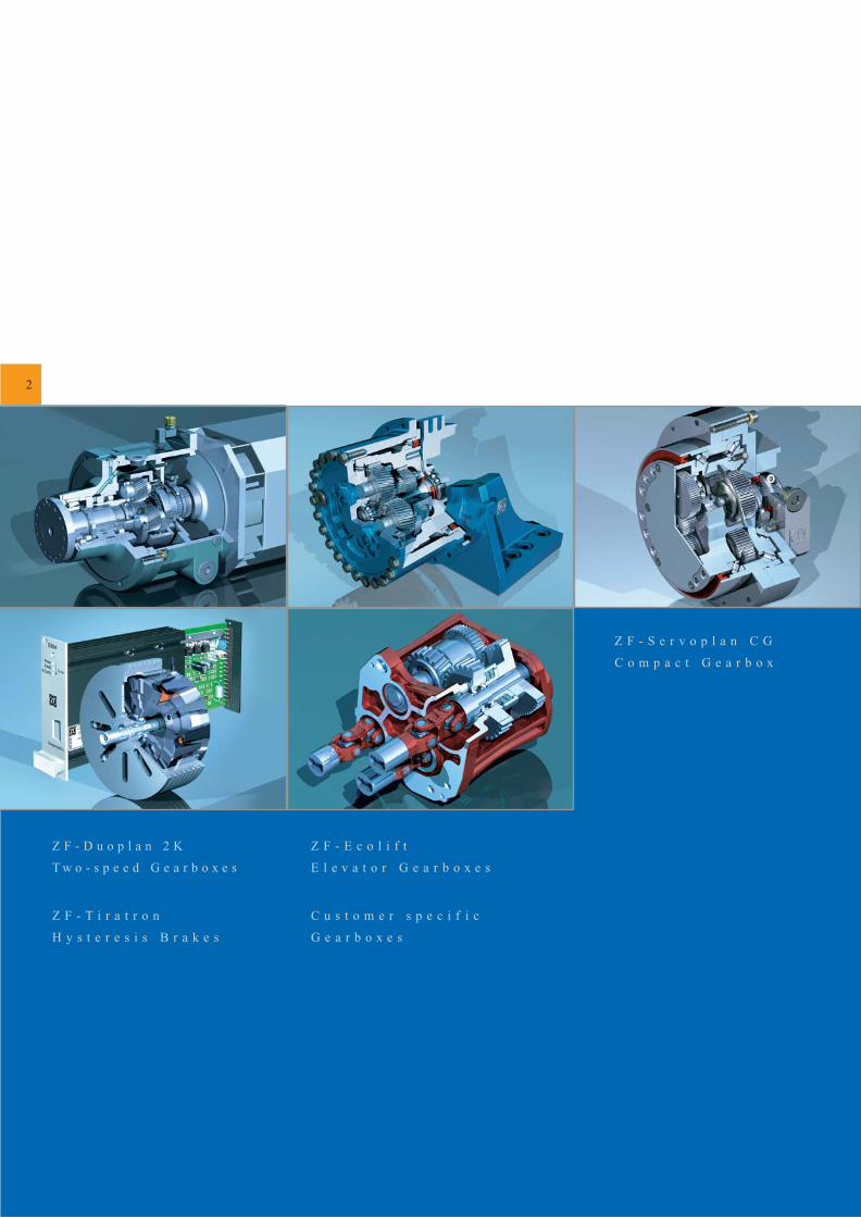
Z F - D u o p l a n 2 K
T w o - s p e e d G e a r b o x e s
Z F - T i r a t r o n
H y s t e r e s i s B r a k e s
C u s t o m e r s p e c i f i c
G e a r b o x e s
Z F - E c o l i f t
E l e v a t o r G e a r b o x e s
Z F - S e r v o p l a n C G
C o m p a c t G e a r b o x
3
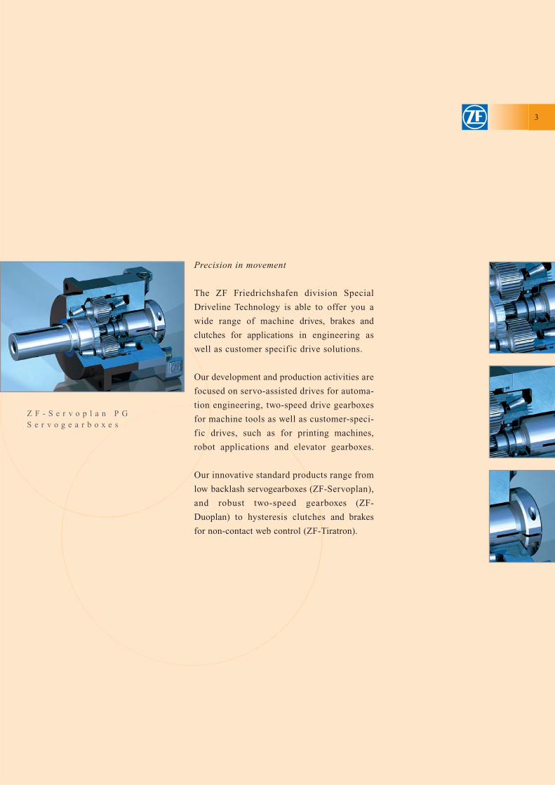
Z F - S e r v o p l a n P GS e r v o g e a r b o x e s
Precision in movement
The ZF Friedrichshafen division Special
Driveline Technology is able to offer you a
wide range of machine drives, brakes and
clutches for applications in engineering as
well as customer specif ic drive solutions.
Our development and production activities are
focused on servo-assisted drives for automa-
tion engineering, two-speed drive gearboxes
for machine tools as well as customer-speci-
f ic drives, such as for printing machines,
robot applications and elevator gearboxes.
Our innovative standard products range from
low backlash servogearboxes (ZF-Servoplan),
and robust two-speed gearboxes (ZF-
Duoplan) to hysteresis clutches and brakes
for non-contact web control (ZF-Tiratron).
Servogea rboxes
4
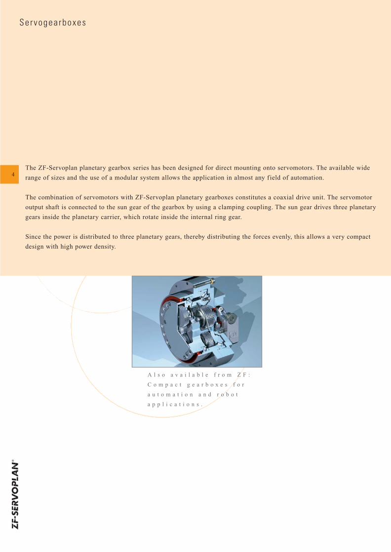
A l s o a v a i l a b l e f r o m Z F :
C o m p a c t g e a r b o x e s f o r
a u t o m a t i o n a n d r o b o t
a p p l i c a t i o n s .
The ZF-Servoplan planetary gearbox series has been designed for direct mounting onto servomotors. The available wide
range of sizes and the use of a modular system allows the application in almost any f ield of automation.
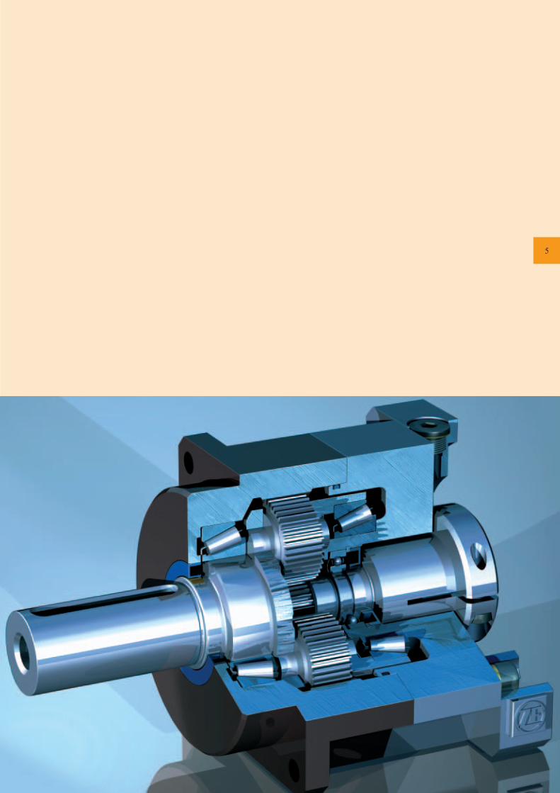
The combination of servomotors with ZF-Servoplan planetary gearboxes constitutes a coaxial drive unit. The servomotor
output shaft is connected to the sun gear of the gearbox by using a clamping coupling. The sun gear drives three planetary
gears inside the planetary carrier, which rotate inside the internal ring gear.
Since the power is distributed to three planetary gears, thereby distributing the forces evenly, this allows a very compact
design with high power density.
5
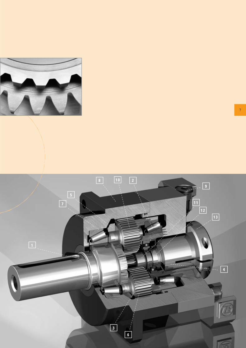
P lane ta r y Gea rboxes
6
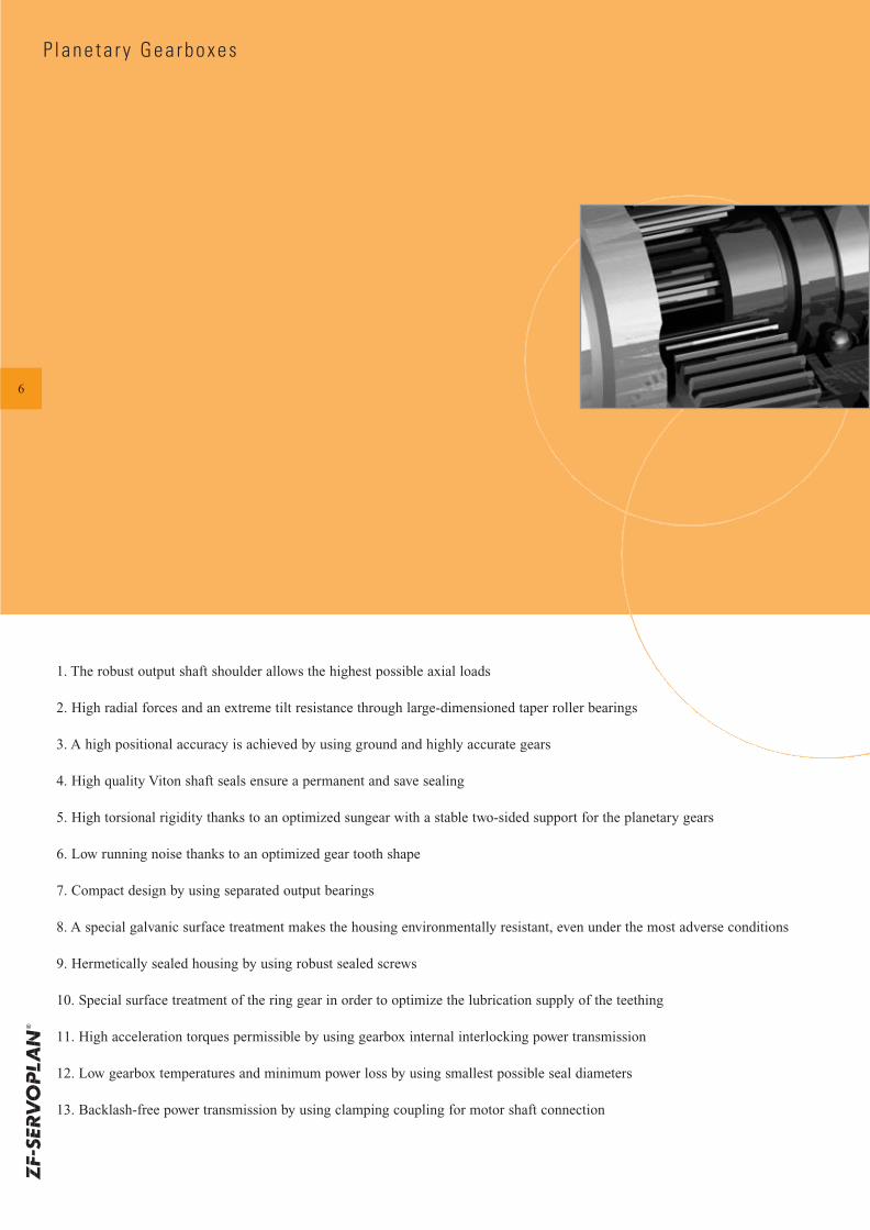
1. The robust output shaft shoulder allows the highest possible axial loads
2. High radial forces and an extreme tilt resistance through large-dimensioned taper roller bearings
3. A high positional accuracy is achieved by using ground and highly accurate gears
4. High quality Viton shaft seals ensure a permanent and save sealing
5. High torsional rigidity thanks to an optimized sungear with a stable two-sided support for the planetary gears
6. Low running noise thanks to an optimized gear tooth shape
7. Compact design by using separated output bearings
8. A special galvanic surface treatment makes the housing environmentally resistant, even under the most adverse conditions
9. Hermetically sealed housing by using robust sealed screws
10. Special surface treatment of the ring gear in order to optimize the lubrication supply of the teething
11. High acceleration torques permissible by using gearbox internal interlocking power transmission
12. Low gearbox temperatures and minimum power loss by using smallest possible seal diameters
13. Backlash-free power transmission by using clamping coupling for motor shaft connection
1
2
3
4
5
1 2
9
1 3
6
7
8
1 1
1 0
7
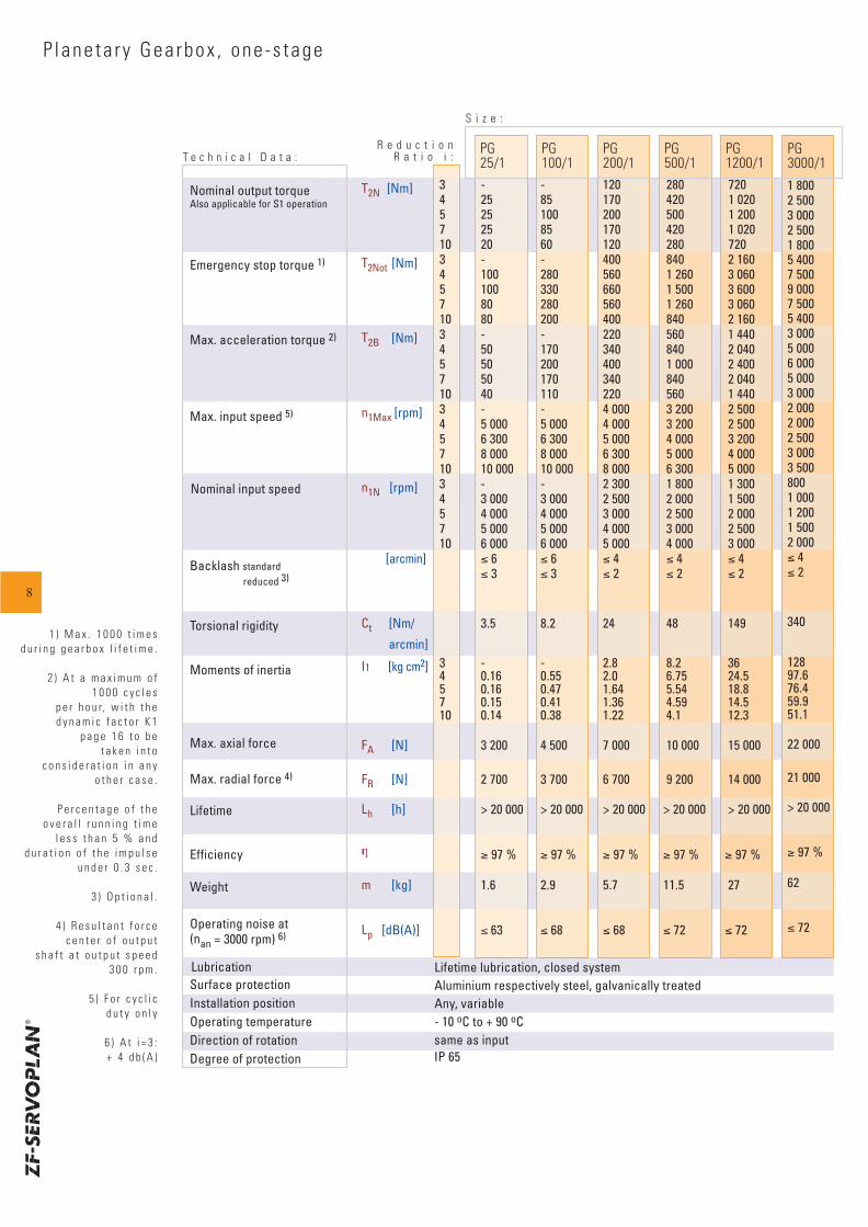
P lane ta r y Gea rbox , one -s tage
T e c h n i c a l D a t a :
S i z e :
T2N [Nm] 3 - - 120 280 7204 25 85 170 420 1 0205 25 100 200 500 1 2007 25 85 170 420 1 02010 20 60 120 280 720
T2Not [Nm] 3 - - 400 840 2 160 5 4004 100 280 560 1 260 3 0605 100 330 660 1 500 3 6007 80 280 560 1 260 3 06010 80 200 400 840 2 160
T2B [Nm] 3 - - 220 560 1 4404 50 170 340 840 2 0405 50 200 400 1 000 2 4007 50 170 340 840 2 04010 40 110 220 560 1 440
n1Max [rpm] 3 - - 4 000 3 200 2 500 2 0004 5 000 5 000 4 000 3 200 2 5005 6 300 6 300 5 000 4 000 3 2007 8 000 8 000 6 300 5 000 4 00010 10 000 10 000 8 000 6 300 5 000
n1N [rpm] 3 - - 2 300 1 800 1 300 8004 3 000 3 000 2 500 2 000 1 5005 4 000 4 000 3 000 2 500 2 0007 5 000 5 000 4 000 3 000 2 50010 6 000 6 000 5 000 4 000 3 000
[arcmin] ≤ 6 ≤ 6 ≤ 4 ≤ 4 ≤ 4≤ 3 ≤ 3 ≤ 2 ≤ 2 ≤ 2
Ct [Nm/ 3.5 8.2 24 48 149
arcmin]
I1 [kg cm2] 3 - - 2.8 8.2 364 0.16 0.55 2.0 6.75 24.55 0.16 0.47 1.64 5.54 18.87 0.15 0.41 1.36 4.59 14.510 0.14 0.38 1.22 4.1 12.3
FA [N] 3 200 4 500 7 000 10 000 15 000
FR [N] 2 700 3 700 6 700 9 200 14 000
Lh [h] > 20 000 > 20 000 > 20 000 > 20 000 > 20 000
≥ 97 % ≥ 97 % ≥ 97 % ≥ 97 % ≥ 97 %
m [kg] 1.6 2.9 5.7 11.5 27
Lp [dB(A)] ≤ 63 ≤ 68 ≤ 68 ≤ 72 ≤ 72
PG25/1
PG100/1
PG200/1
PG500/1
PG1200/1
1 8002 5003 0002 5001 8005 4007 5009 0007 5005 4003 0005 0006 0005 0003 0002 0002 0002 5003 0003 5008001 0001 2001 5002 000≤ 4≤ 2
340
12897.676.459.951.1
22 000
21 000
> 20 000
≥ 97 %
62
≤ 72
PG3000/1
R e d u c t i o nR a t i o i :
Nominal output torqueAlso applicable for S1 operation
Emergency stop torque 1)
Max. acceleration torque 2)
Max. input speed 5)
Moments of inertia
Nominal input speed
Backlash standard reduced 3)
Torsional rigidity
Max. axial force
Max. radial force 4)
Lifetime
Efficiency
Weight
Operating noise at(nan = 3000 rpm) 6)
LubricationSurface protectionInstallation positionOperating temperatureDirection of rotationDegree of protection
Lifetime lubrication, closed systemAluminium respectively steel, galvanically treatedAny, variable- 10 oC to + 90 oCsame as inputIP 65
8
1 ) M a x . 1 0 0 0 t i m e s d u r i n g g e a r b o x l i f e t i m e .
2 ) A t a m a x i m u m o f1 0 0 0 c y c l e s
p e r h o u r, w i t h t h e d y n a m i c f a c t o r K 1
p a g e 1 6 t o b e t a k e n i n t o
c o n s i d e r a t i o n i n a n yo t h e r c a s e .
P e r c e n t a g e o f t h eo v e r a l l r u n n i n g t i m e
l e s s t h a n 5 % a n d d u r a t i o n o f t h e i m p u l s e
u n d e r 0 . 3 s e c .
3 ) O p t i o n a l .
4 ) R e s u l t a n t f o r c ec e n t e r o f o u t p u t
s h a f t a t o u t p u t s p e e d3 0 0 r p m .
5 ) F o r c y c l i cd u t y o n l y
6 ) A t i = 3 : + 4 d b ( A )
D1 D2 D3
max
. D6
D7
L12
L2 L3
L4
L1
L6
L22B
L7
B
L13
D8
D945°
90°DRDIN 332
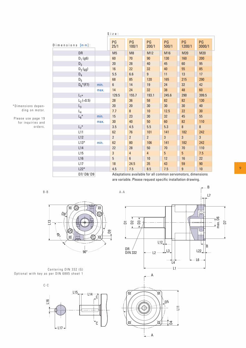
D i m e n s i o n s [m m] :PG25/1
PG100/1
PG200/1
PG500/1
PG1200/1
min.max.
S i z e :
DR M5 M8 M12 M16 M20D1 (g6) 60 70 90 130 160D2 20 28 40 45 60D3 (k6) 16 22 32 40 55D4 5.5 6.6 9 11 13D5 68 85 120 165 215D6*(F7) 6 14 19 24 32
14 24 32 38 48L1* 129.5 155.7 193.1 245.6 290L2 (+0.5) 28 36 58 82 82L3 20 20 30 30 30L4 7.7 8 10 12.5 22L6* 15 23 30 32 45
30 40 50 60 82L7* 3.5 4.5 5.5 5.3 8L11 62 76 101 141 182L12 2 2 2 3 3L13* 62 80 106 141 182L14 22 28 50 70 70L15 3 4 4 5 5L16 5 6 10 12 16L17 18 24.5 35 43 59L22* 4.5 7.5 8.5 7.5 9D7/ D8/ D9 Adaptations available for all common servomotors, dimensions
are variable. Please request specific installation drawing.
PG3000/1
M202009585172904260399.5130403055110824232421107.5229010
min.max.
min.
C e n t e r i n g D I N 3 3 2 ( G )O p t i o n a l w i t h k e y a s p e r D I N 6 8 8 5 s h e e t 1
L16
L17
L15 L14C
C
A
A
L11
D4
D5
* D i m e n s i o n s d e p e n -d i n g o n m o t o r.
P l e a s e u s e p a g e 1 9 f o r i n q u i r i e s a n d
o r d e r s .
B - B A - A
C - C
9
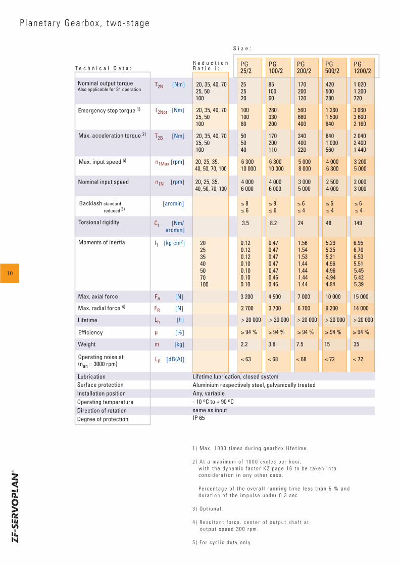
P lane ta r y Gea rbox , two -s tage
max. Axialkraft
Ct [Nm/ 3.5 8.2 24 48 149 arcmin]
[%]
Surface protectionInstallation positionOperating temperatureDirection of rotationDegree of protection
R e d u c t i o nR a t i o i :
S i z e :
PG25/2
PG100/2
PG200/2
PG500/2
PG1200/2
T2N [Nm] 20, 35, 40, 70 25 85 170 420 1 020 25, 50 25 100 200 500 1 200
100 20 60 120 280 720
T2B [Nm] 20, 35, 40, 70 50 170 340 840 2 040 25, 50 50 200 400 1 000 2 400
100 40 110 220 560 1 440
T2Not [Nm] 20, 35, 40, 70 100 280 560 1 260 3 060 25, 50 100 330 660 1 500 3 600
100 80 200 400 840 2 160
n1Max [rpm] 20, 25, 35, 6 300 6 300 5 000 4 000 3 200 40, 50, 70, 100 10 000 10 000 8 000 6 300 5 000
n1N [rpm] 20, 25, 35, 4 000 4 000 3 000 2 500 2 000 40, 50, 70, 100 6 000 6 000 5 000 4 000 3 000
l1 [kg cm2] i = 20 0.12 0.47 1.56 5.29 6.95 i = 25 0.12 0.47 1.54 5.25 6.70
i = 35 0.12 0.47 1.53 5.21 6.53 i = 40 0.10 0.47 1.44 4.96 5.51
i = 50 0.10 0.47 1.44 4.96 5.45 i = 70 0.10 0.46 1.44 4.94 5.42 i = 100 0.10 0.46 1.44 4.94 5.39
Moments of inertia
T e c h n i c a l D a t a :
Nominal output torqueAlso applicable for S1 operation
Emergency stop torque 1)
Max. acceleration torque 2)
Max. input speed 5)
Nominal input speed
Backlash standard reduced 3)
Torsional rigidity
Max. radial force 4)
Lifetime
Efficiency
Weight
Operating noise at(nan = 3000 rpm)
Lubrication
Max. axial force
Lifetime lubrication, closed systemAluminium respectively steel, galvanically treatedAny, variable- 10 oC to + 90 oCsame as inputIP 65
LP [dB(A)] ≤ 63 ≤ 68 ≤ 68 ≤ 72 ≤ 72
m [kg] 2.2 3.8 7.5 15 35
Lh [h] > 20 000 > 20 000 > 20 000 > 20 000 > 20 000
FR [N] 2 700 3 700 6 700 9 200 14 000
≥ 94 % ≥ 94 % ≥ 94 % ≥ 94 % ≥ 94 %
FA [N] 3 200 4 500 7 000 10 000 15 000
202535405070100
[arcmin] ≤ 8 ≤ 8 ≤ 6 ≤ 6 ≤ 6 ≤ 6 ≤ 6 ≤ 4 ≤ 4 ≤ 4
1 ) M a x . 1 0 0 0 t i m e s d u r i n g g e a r b o x l i f e t i m e .
2 ) A t a m a x i m u m o f 1 0 0 0 c y c l e s p e r h o u r, w i t h t h e d y n a m i c f a c t o r K 2 p a g e 1 6 t o b e t a k e n i n t o c o n s i d e r a t i o n i n a n y o t h e r c a s e .
P e r c e n t a g e o f t h e o v e r a l l r u n n i n g t i m e l e s s t h a n 5 % a n d d u r a t i o n o f t h e i m p u l s e u n d e r 0 . 3 s e c .
3 ) O p t i o n a l .
4 ) R e s u l t a n t f o r c e . c e n t e r o f o u t p u t s h a f t a t o u t p u t s p e e d 3 0 0 r p m .
5 ) F o r c y c l i c d u t y o n l y
10
D1 D2 D3
L12
L2 L3
L4L1
L13
D8
D945°
90°DRDIN 332
max
. D6
D7
L6
L22B
L7
B
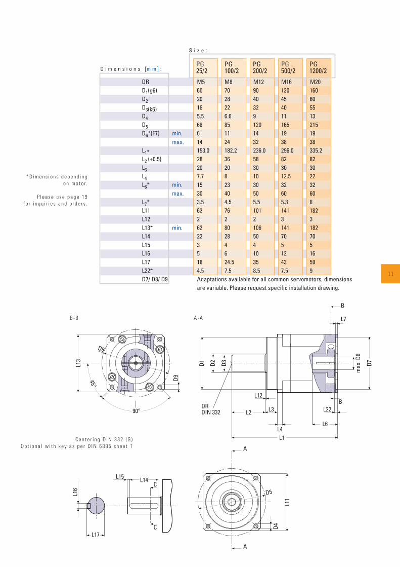
D i m e n s i o n s [m m] :PG25/2
PG100/2
PG200/2
PG500/2
PG1200/2
min.max.
S i z e :
DR M5 M8 M12 M16 M20D1(g6) 60 70 90 130 160D2 20 28 40 45 60D3(k6) 16 22 32 40 55D4 5.5 6.6 9 11 13D5 68 85 120 165 215D6*(F7) 6 11 14 19 19
14 24 32 38 38L1* 153.0 182.2 236.0 296.0 335.2L2 (+0.5) 28 36 58 82 82L3 20 20 30 30 30L4 7.7 8 10 12.5 22L6* 15 23 30 32 32
30 40 50 60 60L7* 3.5 4.5 5.5 5.3 8L11 62 76 101 141 182L12 2 2 2 3 3L13* 62 80 106 141 182L14 22 28 50 70 70L15 3 4 4 5 5L16 5 6 10 12 16L17 18 24.5 35 43 59L22* 4.5 7.5 8.5 7.5 9D7/ D8/ D9 Adaptations available for all common servomotors, dimensions
are variable. Please request specific installation drawing.
min.max.
min.
C e n t e r i n g D I N 3 3 2 ( G )O p t i o n a l w i t h k e y a s p e r D I N 6 8 8 5 s h e e t 1
L16
L17
L15 L14C
C
A
A
L11
D4
D5
* D i m e n s i o n s d e p e n d i n go n m o t o r.
P l e a s e u s e p a g e 1 9 f o r i n q u i r i e s a n d o r d e r s .
B - B A - A
11
L2
FA
x
FR
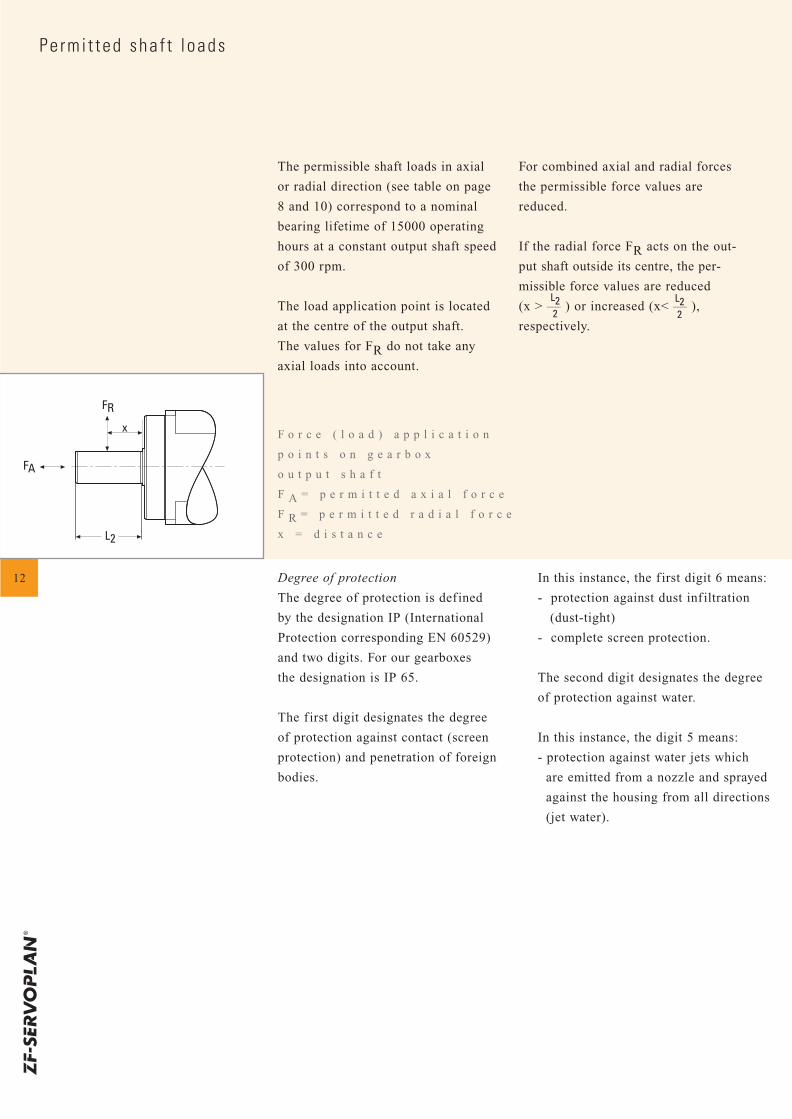
Pe rm i t ted sha f t l oads
12
F o r c e ( l o a d ) a p p l i c a t i o n
p o i n t s o n g e a r b o x
o u t p u t s h a f t
F A = p e r m i t t e d a x i a l f o r c e
F R = p e r m i t t e d r a d i a l f o r c e
x = d i s t a n c e
The permissible shaft loads in axial
or radial direction (see table on page
8 and 10) correspond to a nominal
bearing lifetime of 15000 operating
hours at a constant output shaft speed
of 300 rpm.
The load application point is located
at the centre of the output shaft.
The values for FR do not take any
axial loads into account.
For combined axial and radial forces
the permissible force values are
reduced.
If the radial force FR acts on the out-
put shaft outside its centre, the per-
missible force values are reduced
(x > –– ) or increased (x< –– ),
respectively.
Degree of protection
The degree of protection is defined
by the designation IP (International
Protection corresponding EN 60529)
and two digits. For our gearboxes
the designation is IP 65.
The f irst digit designates the degree
of protection against contact (screen
protection) and penetration of foreign
bodies.
In this instance, the f irst digit 6 means:
- protection against dust infiltration
(dust-tight)
- complete screen protection.
The second digit designates the degree
of protection against water.
In this instance, the digit 5 means:
- protection against water jets which
are emitted from a nozzle and sprayed
against the housing from all directions
(jet water).
L22
L22
Gearbox Ou tpu t Sha f t
TA
FV
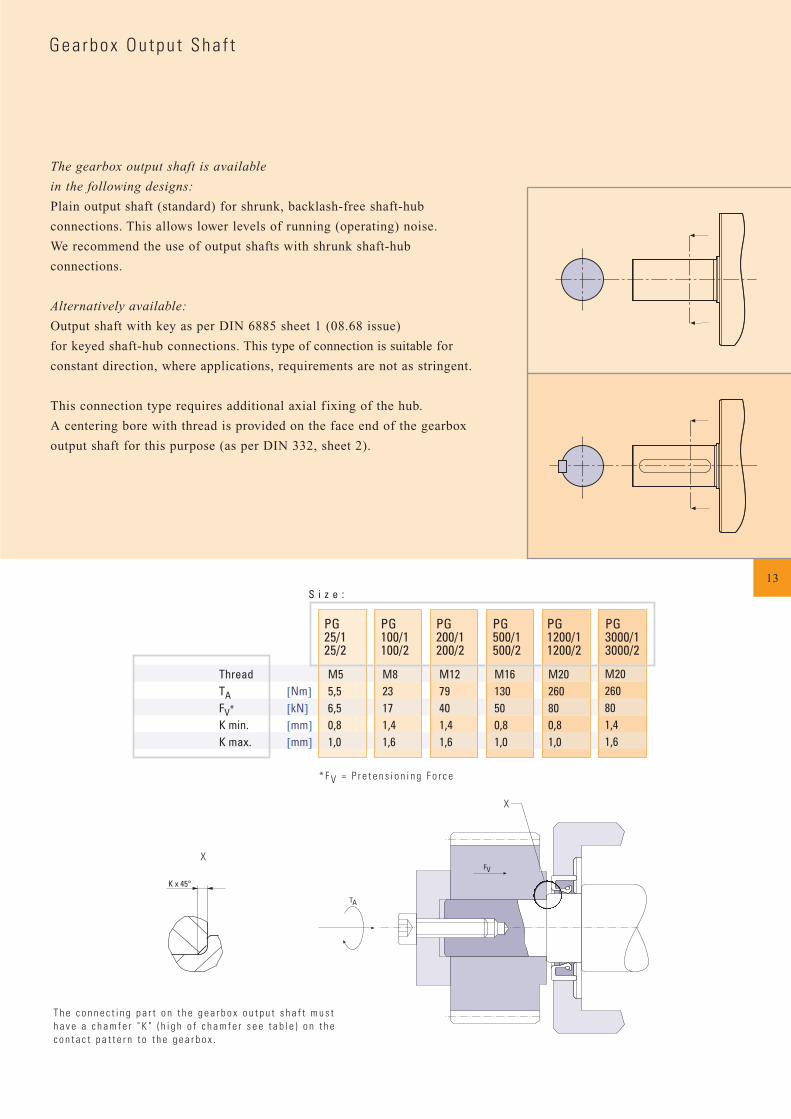
S i z e :
PG25/125/2
PG100/1100/2
PG200/1200/2
PG500/1500/2
PG1200/11200/2
PG3000/13000/2
Thread M5 M8 M12 M16 M20TA [Nm] 5,5 23 79 130 260FV* [kN] 6,5 17 40 50 80K min. [mm] 0,8 1,4 1,4 0,8 0,8K max. [mm] 1,0 1,6 1,6 1,0 1,0
M20260801,41,6
The gearbox output shaft is available
in the following designs:
Plain output shaft (standard) for shrunk, backlash-free shaft-hub
connections. This allows lower levels of running (operating) noise.
We recommend the use of output shafts with shrunk shaft-hub
connections.
Alternatively available:
Output shaft with key as per DIN 6885 sheet 1 (08.68 issue)
for keyed shaft-hub connections. This type of connection is suitable for
constant direction, where applications, requirements are not as stringent.
This connection type requires additional axial f ixing of the hub.
A centering bore with thread is provided on the face end of the gearbox
output shaft for this purpose (as per DIN 332, sheet 2).
* F V = P r e t e n s i o n i n g F o r c e
13
K x 45°
X
X
T h e c o n n e c t i n g p a r t o n t h e g e a r b o x o u t p u t s h a f t m u s th a v e a c h a m f e r " K " ( h i g h o f c h a m f e r s e e t a b l e ) o n t h ec o n t a c t p a t t e r n t o t h e g e a r b o x .
14
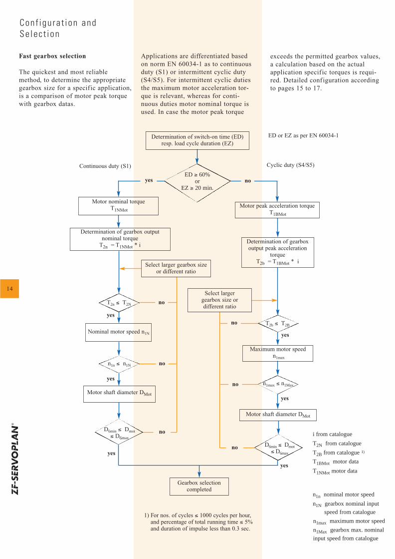
Fast gearbox selection
The quickest and most reliablemethod, to determine the appropriategearbox size for a specif ic application,is a comparison of motor peak torquewith gearbox datas.
Applications are differentiated basedon norm EN 60034-1 as to continuousduty (S1) or intermittent cyclic duty(S4/S5). For intermittent cyclic dutiesthe maximum motor acceleration tor-que is relevant, whereas for conti-nuous duties motor nominal torque isused. In case the motor peak torque
Con f igu ra t i on and Se lec t i on
exceeds the permitted gearbox values,a calculation based on the actualapplication specif ic torques is requi-red. Detailed configuration accordingto pages 15 to 17.
Continuous duty (S1)
T2n ≤ T2N
n1n ≤ n1N
D6min ≤ Dmot≤ D6max
T2b ≤ T2B
n1max ≤ n1Max
D6min ≤ Dmot≤ D6max
Cyclic duty (S4/S5)
ED or EZ as per EN 60034-1
yes
yes
yes
yes
yes
yes
1) For nos. of cycles ≤ 1000 cycles per hour,and percentage of total running time ≤ 5% and duration of impulse less than 0.3 sec.
i from catalogue
T2N from catalogue
T2B from catalogue 1)
T1BMot motor data
T1NMot motor data
n1n nominal motor speed
n1N gearbox nominal input
speed from catalogue
n1max maximum motor speed
n1Max gearbox max. nominal
input speed from catalogue
yes
no
no
no
no
no
no
no
Nominal motor speed n1N
Motor shaft diameter DMot
Motor nominal torqueT1NMot
Determination of switch-on time (ED)resp. load cycle duration (EZ)
Motor peak acceleration torqueT1BMot
Maximum motor speedn1max
Motor shaft diameter DMot
Gearbox selectioncompleted
ED ≥ 60%or
EZ ≥ 20 min.
Determination of gearboxoutput peak acceleration
torque T2b = T1BMot * i
Select larger gearbox sizeor different ratio
Determination of gearbox output nominal torque
T2n = T1NMot * i
Select largergearbox size or different ratio
Con f igu ra t i on and Se lec t i on
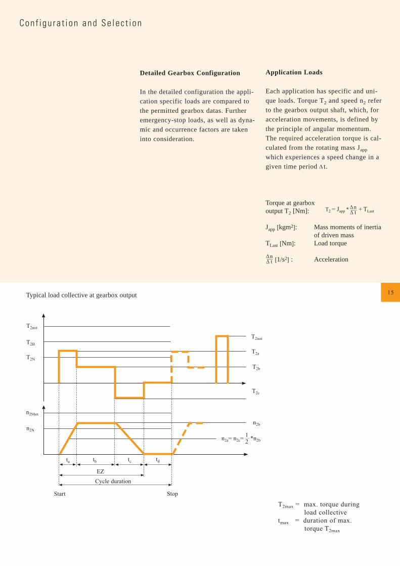
Detailed Gearbox Configuration
In the detailed configuration the appli-
cation specific loads are compared to
the permitted gearbox datas. Further
emergency-stop loads, as well as dyna-
mic and occurrence factors are taken
into consideration.
Application Loads
Each application has specific and uni-
que loads. Torque T2 and speed n2 refer
to the gearbox output shaft, which, for
acceleration movements, is defined by
the principle of angular momentum.
The required acceleration torque is cal-
culated from the rotating mass Japp
which experiences a speed change in a
given time period t.
Torque at gearbox output T2 [Nm]:
Japp [kgm2]: Mass moments of inertia of driven mass
TLast [Nm]: Load torque
[1/s2] : Acceleration
T2 = Japp * + TLastnt
T2not
T2B
T2N
n2Max
n2N
ta tb tc td
EZ
Cycle duration
Start
T2not
T2a
T2b
T2c
n2b
n2a= n2c= *n2b12
nt
Typical load collective at gearbox output
Stop
15
T2max = max. torque during load collective
tmax = duration of max. torque T2max
16
2,5
2,0
1,5
1,0
0,5
00 10 20 30 40 50 60 70 80 90 100Emax (%)
Freq
uenc
y fa
ctor
k2
10,90,80,70,60,50,40,30,20,1
00 1000 2000 3000 4000 5000 6000 7000 8000 9000 10000Nos. of cycles (1/h)
Dyna
mic
fakt
or k
1
Con f igu ra t i on and Se lec t i on
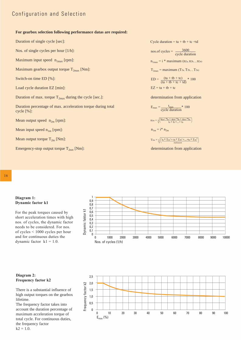
For gearbox selection following performance datas are required:
Duration of single cycle [sec]:
Nos. of single cycles per hour [1/h]:
Maximum input speed n1max [rpm]:
Maximum gearbox output torque T2max [Nm]:
Switch-on time ED [%]:
Load cycle duration EZ [min]:
Duration of max. torque T2max during the cycle [sec.]:
Duration percentage of max. acceleration torque during total cycle [%]:
Mean output speed n2m [rpm]:
Mean input speed n1m [rpm]:
Mean output torque T2m [Nm]:
Emergency-stop output torque T2not [Nm]:
ED = (ta + tb + tc) * 100(ta + tb + tc + td)
EZ = ta + tb + tc
Emax = tmax * 100 cycle duration
T2m = 3 ta * T2a3 + tb * T2b3 +...+tn * T2n3
Zykluszeit
n1m = i* n2m
Diagram 1:Dynamic factor k1
For the peak torques caused byshort acceleration times with highnos. of cycles, the dynamic factorneeds to be considered. For nos.of cycles < 1000 cycles per hourand for continuous duties thedynamic factor k1 = 1.0.
Diagram 2:Frequency factor k2
There is a substantial influence ofhigh output torques on the gearboxlifetime. The frequency factor takes intoaccount the duration percentage ofmaximum acceleration torque oftotal cycle. For continuous duties,the frequency factor k2 = 1.0.
Cycle duration = ta + tb + tc +td
nos.of cycles = 3600 cycle duration
T2max = maximum (T2a, T2b,..., T2n)
n1max = i * maximum (n2a, n2b,..., n2n)
determination from application
determination from application
n2m = 3 n2a3 *ta + n2b3 *tb + n2n3 *tn
ta + tb +...+ tn
Fr ≤ FRFa ≤ FA
T2max ≤ T2Bzul
no
yes
yes
EZ = ta + tb + tc [min]
ED = (ta + tb + tc) * 100 [%](ta + tb + tc + td)
k1 from diagramm 1
i = possible input speed max. output speed
i from catalogue
n1max = i * maximum (n2a, n2b,..., n2n) [rpm]
T2max = maximum (T2a, T2b,..., T2n) [Nm]
T2Bzul. =T2N * k1* k2 [Nm]
T2not depending on application
Cycle duration = ta + tb + tc + td [s]
Nos. of cycles = 3600 [1/h]cycle duration
n1Max from catalogue
Emax = tmax * 100 [%]cycle duration
k2 from diagram 2
T2N from catalogue
T2Not from catalogue
yes
yes
yes
no
no
no
no
yes
yes
T2m = 3 ta * T2a3 + tb * T2b3 +...+tn * T2n3
Zykluszeit
n2m = 3 n2a3 *ta + n2b3 *tb + n2n3 *tn
ta + tb +...+ tn
n1m = i* n2m
17
[rpm]
[Nm]
no
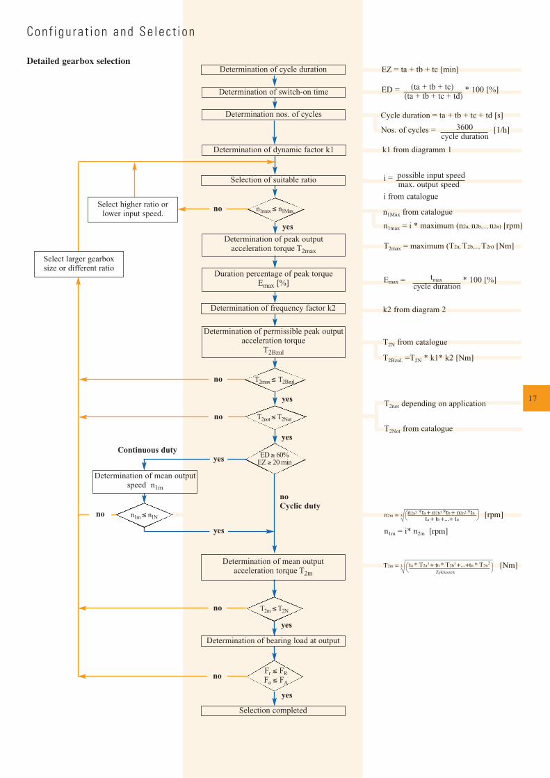
Selection of suitable ratio
n1max ≤ n1Max.
Determination of peak output acceleration torque T2max
T2not ≤T2Not
Select higher ratio orlower input speed.
Select larger gearbox size or different ratio
Duration percentage of peak torque Emax [%]
Determination of frequency factor k2
Determination of permissible peak outputacceleration torque
T2Bzul
ED ≥ 60%EZ ≥ 20 min
Determination of mean outputspeed n1m
Determination of bearing load at output
Selection completed
Determination of mean outputacceleration torque T2m
T2m ≤T2N
n1m ≤ n1N
Continuous duty
no Cyclic duty
Determination of cycle duration
Determination of switch-on time
Determination nos. of cycles
Determination of dynamic factor k1
Con f igu ra t i on and Se lec t i on
Detailed gearbox selection
[rpm]
18
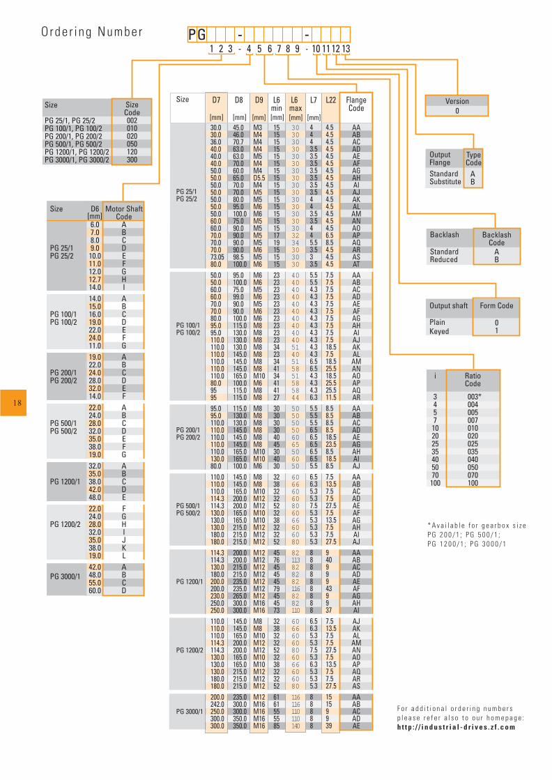
Output shaft
PlainKeyed
Form Code
01
Backlash
StandardReduced
BacklashCode
AB
[mm] [mm] [mm][mm] [mm] [mm]
[mm]
PG 3000/1
1 2 3 - 4 5 6 7 8 9 - 10 11 12 13P G -
OutputFlangeStandardSubstitute
Type Code
AB
Size
PG 25/1, PG 25/2PG 100/1, PG 100/2PG 200/1, PG 200/2PG 500/1, PG 500/2PG 1200/1, PG 1200/2PG 3000/1, PG 3000/2
SizeCode002010020050120300
Version0
Size
PG 25/1PG 25/2
PG 100/1PG 100/2
PG 200/1PG 200/2
PG 500/1PG 500/2
PG 1200/1
PG 1200/2
PG 3000/1
D9
M3M4M4M4M5M4M4D5.5M4M5M5M6M6M5M5M5M5M6M5M6M6M6M5M6M5M6M6M8M8M8M8M8M8M8M10M6M8M8M8M8M8M8M8M8M10M10M6M8M8M10M12M12M10M10M12M12M12M12M12M12M12M12M12M12M16M16M8M8M10M12M12M10M10M12M12M12M12M16M16M16M16
D7
30.030.036.040.040.040.050.050.050.050.050.050.050.060.060.070.070.070.073.0580.050.050.060.060.070.070.080.095.095.0110.0110.0110.0110.0110.0110.080.0959595.095.0110.0110.0110.0110.0110.0130.080.0110.0110.0110.0114.3114.3130.0130.0130.0180.0180.0114.3114.3130.0180.0200.0200.0230.0250.0250.0110.0110.0110.0114.3114.3130.0130.0130.0180.0180.0200.0242.0250.0300.0300.0
D8
45.046.070.763.063.070.060.065.070.070.080.095.0100.075.090.090.090.090.098.5100.095.0100.075.099.090.090.0100.0115.0130.0130.0130.0145.0145.0145.0165.0100.0115.0115.0115.0130.0130.0145.0145.0145.0165.0165.0100.0145.0145.0165.0200.0200.0165.0165.0215.0215.0215.0200.0200.0215.0215.0235.0235.0265.0300.0300.0145.0145.0165.0200.0200.0165.0165.0215.0215.0215.0235.0300.0300.0350.0350.0
L6min
151515151515151515151515151515171915151523232323232323232323342334413441412730303030404530403032383232523238323252457645454579454573323832325232383232526161555585
3030303030303030303030303030303234303030
404040404040404040405140515851585844
505050506065506050
60666060806066606080
821138282821168282110
60666060806066606080
116116110110140
L6max
4443.53.53.53.53.53.53.5443.53.5445.53.533.55.55.54.34.34.34.34.34.34.34.34.34.36.56.54.34.34.36.35.55.55.56.56.56.56.56.55.56.56.35.35.37.55.35.35.35.35.38888888886.56.35.35.37.55.36.35.35.35.388888
L7
4.54.54.54.54.54.54.54.54.54.54.54.54.54.54.56.58.54.54.54.57.57.57.57.57.57.57.57.57.57.518.57.518.525.518.525.525.511.58.58.58.58.518.523.58.518.58.57.513.57.57.527.57.513.57.57.527.59409994399377.513.57.57.527.57.513.57.57.527.515159939
L22 FlangeCode
AAABACADAEAFAGAHAIAJAKALAMANAOAPAQARASATAAABACADAEAFAGAHAIAJAKALAMANAOAPAQARAAABACADAEAGAHAIAJAAABACADAEAFAGAHAIAJAAABACADAEAFAGAHAIAJAKALAMANAOAPAQARASAAABACADAE
-
D6
6.07.08.09.010.011.012.012.714.014.015.016.019.022.024.011.019.022.024.028.032.014.022.024.028.032.035.038.019.032.035.038.042.048.022.024.028.032.035.038.019.042.048.055.060.0
Motor ShaftCode
ABCDEFGHIABCDEFGABCDEFABCDEFGABCDEFGHIJKLABCD
Size
PG 25/1PG 25/2
PG 100/1PG 100/2
PG 200/1PG 200/2
PG 500/1PG 500/2
PG 1200/1
PG 1200/2
i
345710202535405070100
RatioCode
003*004005007010020025035040050070100
Orde r i ng Number
* A v a i l a b l e f o r g e a r b o x s i z eP G 2 0 0 / 1 ; P G 5 0 0 / 1 ;P G 1 2 0 0 / 1 ; P G 3 0 0 0 / 1
F o r a d d i t i o n a l o r d e r i n g n u m b e r sp l e a s e r e f e r a l s o t o o u r h o m e p a g e :h t t p : / / i n d u s t r i a l - d r i v e s . z f . c o m
Subject to technical change without notice. For studies, please request installation drawings; only the data contained therein is binding. Please refer also to our homepage: http:// industrial-drives.zf.com
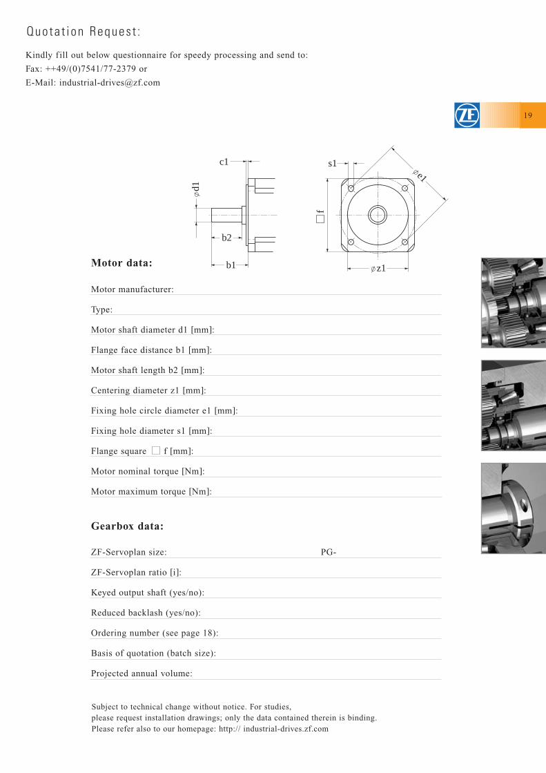
Kindly f ill out below questionnaire for speedy processing and send to:
Fax: ++49/(0)7541/77-2379 or
E-Mail: [email protected]
Quota t i on Reques t :
Motor manufacturer:
Type:
Motor shaft diameter d1 [mm]:
Flange face distance b1 [mm]:
Motor shaft length b2 [mm]:
Centering diameter z1 [mm]:
Fixing hole circle diameter e1 [mm]:
Fixing hole diameter s1 [mm]:
Flange square f [mm]:
Motor nominal torque [Nm]:
Motor maximum torque [Nm]:
ZF-Servoplan size: PG-
ZF-Servoplan ratio [i]:
Keyed output shaft (yes/no):
Reduced backlash (yes/no):
Ordering number (see page 18):
Basis of quotation (batch size):
Projected annual volume:
Motor data:
Gearbox data:
z1
e1s1
f
c1
b2
b1
d1
19
ZF Friedrichshafen AG
Special Driveline Technology
Ehlersstrasse 50
88046 Friedrichshafen/Germany
Phone: +49(0)7541-77-0
Fax: +49(0)7541-77-2379
e-Mail: [email protected]
Internet: http://industrial-drives.zf.com
Pri
nt:
4152
750
101
dS
ubje
ct t
o te
chni
cal
chan
ge w
itho
ut n
otic
e. F
or s
tudi
es,
plea
se r
eque
st i
nsta
llat
ion
draw
ings
; on
ly t
he d
ata
cont
aine
d th
erei
n is
bin
ding
.