Embed Size (px)
Citation preview
Z Technology, Inc.DSS5600T DriveTest™ System with Diversity DVB-T Decoders
Comprehensive Field Measurement and Documentation System for the DVB-T Digital Television Standard
Incorporates Programmable Field Strength Meter, Diversity DVB-T Decoder, & GPS Receiver Controlled via DriveTest™ Application
Graphic Display of RF Spectrum & DVB-T Parameters vs. Time
Records Clear Text Values for Inte-grated Power, Peak Power, Bandpass Tilt, In-Band Notches, Std. Deviation, FMT, Alpha, HP & LP Code Rate, Car-rier, TPS, Viterbi, FEC and MPEG Sync Locks, M-SNR, Pre-Viterbi Bit Error Rate, Pre-RS Bit Error Rate, Post-RS Bit Error Rate, MER, BER, PER, QEF, SQI and GPS Parameters
Rugged Design Provides Maximum Portability and Capabilities for Acquiring Data from Difficult to reach Locations
Measures and Maps Digital and Analog Signal Coverage on Embedded Maps and Customer-Licensed Image Files.
The DSS5600T is a DVB-T (COFDM) portable Terrestrial Broadcast Measurement System. The unit is a self contained system incorporating a laptop PC running proprietary Z Technology DriveTest™ Application Software.The System features RF field strength and Digital Television (DVB-T) decoded parameter measure-ments while adding unique plotting and mapping capabilities. Using this Windows™ based system, a Broadcaster can easily generate signal coverage data including a full set of figure-of-merit parameters for DVB-T signals and plot these over a service area. Problems may be analyzed quickly to determine appropriate cor-rective action for improved signal coverage.
The DSS5600T provides all the capability of an RF Signal Level Measurement System with the added advantage of DVB-T Digital Television Signal Decoding. Extensive RF and DVB-T decoded parameter measurement capability is contained within this one compact, easy to use package. The System is made up of precision RF mea-suring hardware, a diversity DVB-T decoder, WAAS-enabled GPS receiver, a Windows™ based laptop PC, and Z Technology DriveTest™ Application Software. It is a compact suitcase sized system to allow use in the laboratory and also in portable or mobile environments.
Precision Measurements:The DSS5600T is a unique turnkey system for automatic data measurement, collec-tion, storage and presentation. Parameters are continuously measured and stored in data files. During data capture, as well as at a later time, parameters can be plotted in color over maps of coverage areas. Plots and collected data are both available for analysis, print out and export to other programs.
The system takes advantage of the preci-sion and flexibility of Z Technology’s programmable field strength meter technol-ogy to provide accurate, high-speed signal strength measurements under PC control. When used with a calibrated antenna, the
DSS5600T Windows™ Based DVB-T Broadcast Signal Analysis / Mapping System
DSS5600T provides a comprehensive facility for NIST traceable RF power measurement and documentation of digital or analog signal coverage.
In addition to RF measurements, the system’s diversity DVB-T decoder provides COFDM signal analysis of demodulated parameters necessary to fully characterize a DVB-T signal. Several decoder figure-of-merit parameters are captured, measured and recorded during a data collection session.
This Digital Signal Analysis System includes the factory installed DriveTest™ Automated Measurement Program. This Application is a Windows™ based program that uniquely integrates three separate yet related features: Data Collection, Dot Plotting, and Swept Display Analysis.Data Collection:The Data Tab is the control center of the DriveTest™ Application. From this screen location, recording sessions (or Jobs) are initiated. Recorded data can be viewed during operation and the status of the subsystems within the DSS5600T is constantly visible allowing review of proper operation.
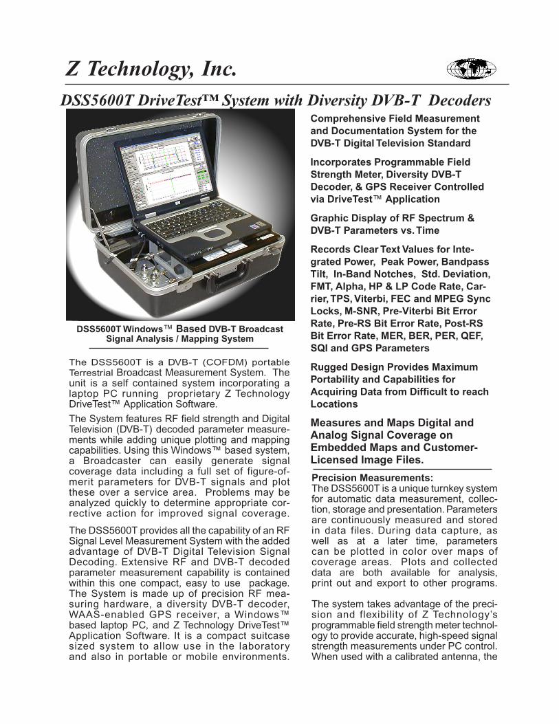
Live plotting of GPS determined positions can be viewed while testing is in process and for many locations can be overlaid on maps. Upon completion of the first segment of a DriveTest™, the software automatically assigns colors to the dot trail of a driven path where colors cor-respond to signal strength, or any one selected RF or Decoded figures-of-merit. The operator can customize colors and transition points to best highlight acceptable versus insufficient measurement results. During a DriveTest™, GPS plots can be viewed based on different operator criteria. The operator can zoom in or out as necessary to properly evaluate signal parameters being displayed in color all during an active measurement test sequence.
The DSS5600T records over 50 parameters to a clear text data file for each DVB-T measurement
Real-Time map plot of a Drive TestSee Options MD01 and MD02
Data Collection automates the process of logging against GPS locations and records several precise RF characteristics including field strength measurements and RF figure-of-merit parameters. These include peak signal power, integrated power, band pass tilt, signal notches and standard deviation of in-band power. In addition to RF characteristics, the DSS5600T also records DVB-T specific decoded parameters into data collection files. Important and useful parameters recorded include Antenna, FFT, Guard, FMT, Alpha, HP Code Rate, LP Code Rate, and for each of the two receiver channels,
AGC Lock, Carr Lock, TPS Lock, Vit Lock, MPEG-Sync Lock, MPEG-Data Lock, Bad MPEG Pkt, QEF, Cell ID, MER, BER, PER, SNR, and SQI. These figures-of-merit are invaluable when determining DVB-T signal coverage. A Job is first defined using the straight forward “Create Job” tool. The Data Collection applica-tion can then be started before the vehicle is placed in motion. The system will initialize and begin accumulating data without further attention.If desired, data for DVB-T and Analog television signals can be measured and stored in data files all during the same DriveTest™. One or many DVB-T and/or Analog television signals may be measured during one session. This is an invaluable tool when working in today’s mixed analog and digital signal environments.Map Plotting:The Plot Tab of the DriveTest™ Software is used to display plots and maps of test results during or after a DriveTest™ session has occurred.
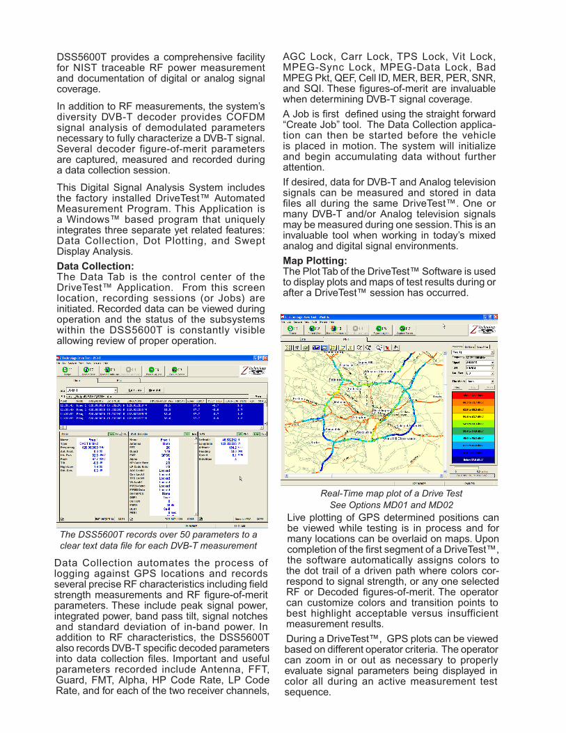
DSS5600A DVB-T Signal Analysis System with COFDM Decoding. System shown being used in the field in a portable application.
Mapping OptionsZ Technology provides Drive-Test System operators with several “real-time” as well as “post-measurement” mapping choices. Real-time maps are visible during an active measurement sequence, with critical information appearing on the map as measurements are being made. Real-time maps become visible by selecting the Plot tab within the DriveTest™. These maps remain active on the screen while collecting measured data. Colored dots indicating GPS locations appear on “real-time” maps as an operator moves from place to place and measures signal parameters.Depending on location, users will find real-time maps provide varying levels of country and/or provincial borders and road level data. Europe and the USA have the most detailed information on real-time maps including expressways, highways and major arterial roads. Other areas may have less detail.
Note: Users can also add real-time map data to their DriveTest™ Systems. Most countries have local map data providers who offer this service at varying levels of detail and at various pricing options. Z Technology provides detailed information concerning directory structures within DriveTest™ used to store locally purchased map data. Data must be provided in specific vendor formats and file structures.Data must be provided in compatible ESRI TM file and format standards. Several other requirements must be met in order for local data to be effectively displayed within DriveTest™. Contact a Z Technology Authorized Distributor or the Factory for implementation details.
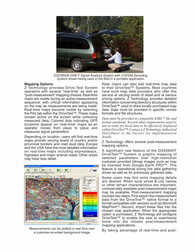
Z Technology offers several post-measurement mapping options. A significant new feature of the DSS5600T DriveTest™ System is graphic mapping of selected parameters over high-resolution customer provided bitmap images such as may be licensed from Google Earth PRO™. This feature is operational during live data gathering drives as well as for previously gathered data.Some users may find extra mapping details are desired. When local street & city names or other terrain characteristics are important, commercially available post-measurement maps may be available. Post-measurement mapping involves two steps. First export the measurement data from the DriveTest™ native format to a format compatible with vendors such as Microsoft MapPointTM. Second, import these files into the chosen map application. When the appropriate option is purchased, Z Technology will configure DriveTest™ to enable the user to seamlessly move into the chosen post-measurement mapping applications. By taking advantage of real-time and post-Measurements can be plotted in real time over
a customer-provided background image
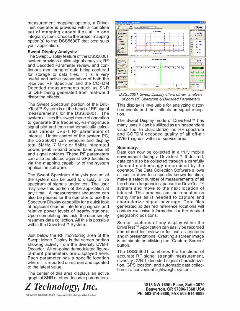
measurement mapping options, a Drive-Test operator is provided with a complete set of mapping capabilities all in one integral system. Choose the proper mapping option(s) to the DSS5600T that best suits your application.Swept Display Analysis:The Swept Display feature of the DSS5600T system provides active signal analysis, RF and Decoded Parameter review, and con-tinuous monitoring of data being captured for storage to data files. It is a very useful and active presentation of both the received RF Spectrum and the COFDM Decoded measurements such as SNR or QEF being generated from real-world distortion effects.
The Swept Spectrum portion of the Driv-eTest™ System is at the heart of RF signal measurements for the DSS5600T. The system utilizes this swept mode of operation to generate the frequency-vs-magnitude signal plot and then mathematically calcu-lates various DVB-T RF parameters of interest. Under control of the system PC, the DSS5600T can measure and display total 6MHz, 7 MHz or 8MHz integrated power, peak in-band power, band pass tilt and signal notches. These RF parameters can also be plotted against GPS locations via the mapping capability of the system application software.
The Swept Spectrum Analysis portion of the system can be used to display a live spectrum of signals under test. The user may view this portion of the application at any time. A measurement sequence can also be paused for the operator to use the Spectrum Display capability for a quick look at adjacent channel interfering signals and relative power levels of nearby stations. Upon completing this task, the user simply resumes data collection. All this is possible within the DriveTest™ System.
Just below the RF monitoring area of the Swept Mode Display is the screen portion showing activity from the diversity DVB-T Decoder. All on-going demodulated figure-of-merit parameters are displayed here. Each parameter has a specific location where it is reported on-screen and updated to the latest value. The center of this area displays an active graph of SNR or other decoder parameters.
DSS5600T Swept Display offers off-air analysis of both RF Spectrum & Decoded Parameters
This display is invaluable for analyzing distor-tion events and their effects on signal recep-tion.The Swept Display mode of DriveTest™ has many uses. It can be utilized as an independent visual tool to characterize the RF spectrum and COFDM decoded quality of all off-air DVB-T signals within a service area.
Summary:Data can now be collected in a truly mobile environment during a DriveTest™. If desired, data can also be collected through a carefully planned methodology determined by the operator. The Data Collection Software allows a user to drive to a specific known location, make a select number of measurements of all the chosen frequencies, pause the DriveTest™ system and move to the next location of interest. This process can be repeated as many times as is needed to capture and characterize signal coverage. Data files generated at desired reference locations will contain exclusive information for the desired geographic positions.
Screen captures of any display within the DriveTest™ Application can easily be recorded and stored for review or for use as printouts and in presentations. Creating a screen image is as simple as clicking the “Capture Screen” button. The DSS5600T combines the functions of accurate RF signal strength measurement, diversity DVB-T decoded signal characteriza-tion, GPS location, and automatic data collec-tion in a convenient lightweight system.
Z Technology, Inc. 1815 NW 169th Place, Suite 3070Beaverton, OR 97006-7368 USA
Ph: 503-614-9800, FAX 503-614-9898DSS5600T 12082005 10000 Data subject to change without notice
DSS5600T DriveTest™ System Specifications:Sensitivity: FM detection: 1 mV for 12 dB SINAD typical AM detection: 1 mV for 12 dB S/N typical
System Measurement Resolution: 0.1dB
Output Linearity Range:Continuous measurement range of 80 dB in auto-rang-ing mode
IF Bandwidth: Narrowband = 15 KHz Wideband = 150 KHz
Input Impedance: 50 Ohms
DECODER SYSTEM SPECIFICATIONSClass of Decoder: COFDM DVB-T Diversity Type
Decoder Description: A fully compliant decoder designed to operate in DVB-T environments. Fully com-pliant in all aspects of the ETS 300 744 Specifications.
Decoder features: Capable of implementing the 2K and 8K FFT. 1/4, 1/8, 1/16, and 1/32 guard intervals are supported as well as QPSK, 16-QAM and 64 QAM constellations. 6 MHz, 7 MHz and 8 MHz wide IF band-widths are selectable.
Automatic transmission mode detection: Automatically detects transmission mode including number of carriers and guard interval used.
FEC Decoder: FEC decoder is comprised of Viterbi Decoder followed by Reed Solomon (RS) decoder.
Demodulator: Uses DIBCOM chip set, optiminzed for difficult channels and moble applications. All DVB-T demodulation modes are supported including hierarchi-cal ones. Antenna diversity mode of operation is sup-ported (Maximum Ratio Combining -MRC.)
Decoder Signal Parameters, Measurements and Stor-age: Diversity Decoder signal parameters measured and recorded into data files:
AGC Lock 1 & 2Carrier Lock 1 & 2TPS Lock 1 & 2Viterbi Lock 1 & 2MPEG-Sync Lock 1 & 2MPEG-Data Lock 1 & 2Bad MPEG Pkt 1 & 2QEF 1 & 2SQI 1 & 2Cell ID 1 & 2MER 1 & 2BER 1 & 2PER 1 & 2SNR 1 & 2Code Rate HP/ LP
The DSS5600T DVB-T (COFDM) Terrestrial TV Broadcast Measurement System is a Windows™ based portable system. The DSS5600T offers extensive RF and COFDM decoded parameter measurement capability. The DSS5600T is designed for automatic data mea-surement, collection and storage. Parameters are stored in open format comma delimited data files. Data can be plotted in color over maps of coverage areas. Collected data is available for analysis, print out and easy export to several other programs.
SYSTEM RF SPECIFICATIONSFrequency Range: DVB-T Decoder covers high VHF & and all UHF Systems B, D, G, & I Television Channels
Extended coverage: 5 -1000 MHz contiguous RF cover-age including all analog VHF and UHF Television Chan-nels with minimum step size of 1KHz
Measurement Range: -10 dBuV to + 90 dBuV (-117 dBm to -17 dBm) using 4 internal Attenuation Ranges & 1 Preamp Range
Measurement Accuracy: +/-2 dB @ 25 degrees +/-10 degrees C. in Field Strength Meter Mode. Typical in Sweep Modes & for temperature range of 0 to 50 degrees C.
Some modulation types influence measurement accu-racy. For analog video modulation, the signal level of the vertical sync peak is measured. This adds 0.5dB additional uncertainty, widening the above specification to +/- 2.5dB.
Power Readout Capability: dBm, dBuV or dBuV/M(dBuV/M reading requires optional calibrated antenna)
RF Signal Parameters Measurements and Storage Parameters Measured & Recorded to data files (Band-pass settable from 1 -- 9 MHz):
1) Total Integrated Power2) Peak Power3) In-Band Tilt4) In-Band Notches (Hi-Lo Diff) 5) In-Band Std Deviation of Power
Image Rejection: 60 dB typical, High Sensitivity mode
Detuning Characteristics: 40 dB typical; for undesired signal 2x IF BW away from center frequency
Third Order Intercept: Preamp ON typ. 0 dBm Preamp OFF typ. +20 dBm
Noise Figure: Preamplifier NF = 7 dB typical when RF AMP is selected.
Audio Detection: AM or FM to internal speaker selected from front panel
DSS5600T DriveTest™ System Specifications
Z Technology, Inc.This product is manufactured in the USA by Z Technology, Inc., and caries a 1 year warranty.
For additional information please contact the factory.1815 NW 169th Place, Suite 3070Beaverton, OR 97006-7368 USA
Ph: 503-614-9800, FAX 503-614-9898www.ztechnology.com
DSS5600T 12082005 10000 Data subject to change without notice
GPS RECEIVER & ANTENNA SPECIFICATIONSGeneral Description: L1 frequency, C/A code (1.023MHz chip rate), 12-channel continuous track-ing receiver. Sensitivity to -170dBW. Accuracy: Horizontal position-15 meters rms, WAAS accuary to - 5 meters rms. (WAAS must be enabled manually by user.)Datum: WGS-84Acquisition rate: Hot start - 8 sec. (ephemeris and almanac valid)Warm start - 38 sec. (almanac valid; ephemeris not)Cold start - 45 sec. (neither almanac or ephemeris)Reacquisition - 0.1 second averageI/O Protocol options: NMEA 0183 v2.2 @ 4800baud, 8-None-1NMEA messages: Standard: GGA, GSA,GSV, RMC Optional: VTG, GLL
Connector: USB for power and all communicationsPower(from USB port): +5VDC 90 ma typical Physical characteristics: receiver integrated with antenna. Entire package magnetically mounted and must be within clear view of sky.
COMPUTERLaptop Computer: Windows™ OS, Speed of 1500 MHz or better and at least 512 Mb Memory
SYSTEM PHYSICAL SPECIFICATIONSSystem Power Requirements: 12VDC at 3.5AMP or 120/220VAC (specify on order).Power Inverter: 12V DC input - 120V or 220V AC output, 150 watts.Certifications: CE System Dimensions: 216 mm (8.5 in) High x 375 mm(14.75 in)Deep x 470 mm (18.5 in) WideSystem Weight 13.9 Kg (29 lbs.)System Operating Temp: +10 to +40 Deg. C
Options:MD 01 Real-Time North American Map DataMD 02 Real-Time European Map DataMA 04 Post-Measurement Microsoft MapPoint ™ USAMA 05 Post-Measurement Microsoft MapPoint ™ EuropeMA 06 Post-Measurement Custom Mapping
Accessories:AA1-B1: Calibrated tuned dipole antenna 30 - 70 MHzAA1-B2: Calibrated tuned dipole antenna 65 - 180 MHzAA1-B3: Calibrated tuned dipole antenna 170 - 340MHzAA1-B4: Calibrated tuned dipole antenna 325 - 1000 MHzAA-TV SET: Calibrated tuned dipole antenna Set 57 - 806 MHz
AA-3 Biconical antenna system 20 MHz - 330 MHzAA-4 Log Periodic antenna system 290 MHz - 1000 MHz AA-6 Log Periodic antenna system 150 MHz - 1000 MHzAA-7 Bi-Log Periodic antenna system 25 MHz - 1000 MHz
Option M: Magnet Mount System for tuned dipole antenna
APPLICATION SOFTWARE, DATA STORAGE & DATA FORMATSApplication Software: Windows™ 98/XP based Auto-mated Drive Test Measurement Software includes the following:1) Data Collection: Provides for orderly collection and storage of RF and Decoded Figures-of-Merit Parameters outlined in the above sections.
2) Dot Plotting/Mapping: Allows GPS locations to be plotted and viewed during and after testing. Colors are assigned to the dot trail of the driven path and indicate range of parameter. Colors correspond to any one (1) selected RF or Decoded Figures-of-Merit Parameter.
3) Sweep Analysis: Displays spans of 5MHz, 10MHz or 20MHz. RF Parameters calibrated in 10MHz & 20MHz (150KHz BW). Acquisition Sweep Rates in these two modes: 550msec per sweep. Sweep refresh rate depends on Decoder settings.
4) Export: Formats comma delimited data for popular mapping and analysis applications such as ExcelTM, MapPointTM, AccessTM, EDXTM, RadiosoftTM, etc.
All measured RF & Decoded Figures-of-Merit Param-eters are displayed for users review and analysis.
Data Storage: Data Stored on PC Hard Drive under open folder and file hierarchy.
Data Format: Format is comma delimited non propri-etary files accessible for importing into other standard utilities.
New values recorded into the data file for each COFDM signal measurement include: Date, Time, Name, Frequency, Latitude, Longitude, Integrated Power, Peak Power, Tilt, High-Low diff, Standard Deviation, Format, Antenna, FFT, Guard, Alpha, HP Code Rate, LP Code Rate, AGC Lock1, Carr Lock1, TPS Lock1, Vit Lock1, MPEG-Sync Lock1, MPEG-Data Lock1, Bad MPEG Pkt1, QEF1, Cell ID1, MER1, BER1, PER1, SNR1, SQI1, AGC Lock2, Carr Lock2, TPS Lock2, Vit Lock2, MPEG-Sync Lock2, MPEG-Data Lock2, Bad MPEG Pkt2, QEF2, Cell ID2, MER2, BER2, PER2, SNR2, SQI2.
The data file also includes information on vehicle heading and speed, instrument attenuator and RF pre-amplifier settings, and parameter units.