Embed Size (px)
Citation preview

8/10/2019 Z Source Converter
http://slidepdf.com/reader/full/z-source-converter 1/12
Z - SOURCE CONVERTERS

8/10/2019 Z Source Converter
http://slidepdf.com/reader/full/z-source-converter 2/12
•What is Z source Converter? Why Z source ?
•V- Source converter and its limitations
•I - Source Converter and its limitations
V-Source inverter:
ac output voltage is < the dc voltage or the dc-voltage > the ac input voltage.
The V-source inverter is a buck inverter for dc-to-ac power conversion and is
a boost (step-up) rectifier for ac-to-dc power conversion.
Additional dc-dc boost converter is needed for higher ac voltages.
The upper and lower devices of each phase leg cannot be gated on to avoid
shoot through fault EMI may cause shoot through; and to avoid dead time is
needed between upper and lower devices adding to cost and controlcomplexity.
An LC output filter is needed to provide sinusoidal output voltage.
8/10/2019 Z Source Converter
http://slidepdf.com/reader/full/z-source-converter 3/12
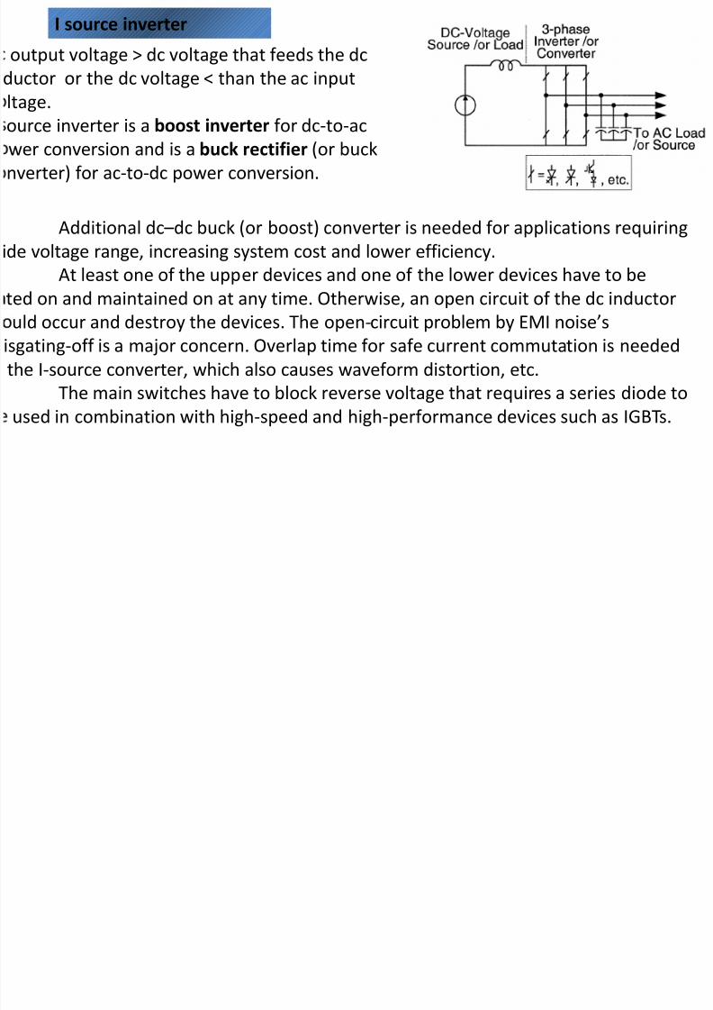
Additional dc –dc buck (or boost) converter is needed for applications requiring
ide voltage range, increasing system cost and lower efficiency.
At least one of the upper devices and one of the lower devices have to be
ted on and maintained on at any time. Otherwise, an open circuit of the dc inductor
uld occur and destroy the devices. The open-circuit problem by EMI noise’s
isgating-off is a major concern. Overlap time for safe current commutation is needed
the I-source converter, which also causes waveform distortion, etc. The main switches have to block reverse voltage that requires a series diode to
used in combination with high-speed and high-performance devices such as IGBTs.
I source inverter
output voltage > dc voltage that feeds the dc
ductor or the dc voltage < than the ac input
ltage.
ource inverter is a boost inverter for dc-to-acwer conversion and is a buck rectifier (or buck
nverter) for ac-to-dc power conversion.

8/10/2019 Z Source Converter
http://slidepdf.com/reader/full/z-source-converter 4/12

8/10/2019 Z Source Converter
http://slidepdf.com/reader/full/z-source-converter 5/12
Z-source converter structure using the antiparallel combination of switching device
and diode.
Z-source converter structure using the series combination of switching device and
diode.

8/10/2019 Z Source Converter
http://slidepdf.com/reader/full/z-source-converter 6/12
Traditional two-stage power conversion for fuel-cell applications.
Z-source inverter for fuel-cell applications.

8/10/2019 Z Source Converter
http://slidepdf.com/reader/full/z-source-converter 7/12

8/10/2019 Z Source Converter
http://slidepdf.com/reader/full/z-source-converter 8/12

8/10/2019 Z Source Converter
http://slidepdf.com/reader/full/z-source-converter 9/12
Modified carrier-based PWM control with shoot-through zero states that are evenly
distributed among the three phase legs, while the equivalent active vectors are unchanged.

8/10/2019 Z Source Converter
http://slidepdf.com/reader/full/z-source-converter 10/12
For the inverter bridge in the shoot-through zero state for an interval of T0
during a switching cycle, one can write v L = VC and v d = 2VC and v out = 0 (2)
and for the non shoot through six states we can write:
v L = Vin – VC, v d= Vin, vout = VC – v L = 2VC – Vin (3)
Where, Vin is the dc source voltage and T = T0 + T1.
Avg voltage of the inductor over one switching period in steady state should be zero
or
Similarly, avg dc link voltage is given by:
Peak dc link voltage of eqn (3) can be expressed as:
Where, B is boost factor
CIRCUIT ANALYSIS AND OBTAINABLE OUTPUT VOLTAGE
Assuming L1=L2=L and C1=C2=C
VC1 = VC2 = VC, and v L1 = v L2= v L (1)
8/10/2019 Z Source Converter
http://slidepdf.com/reader/full/z-source-converter 11/12
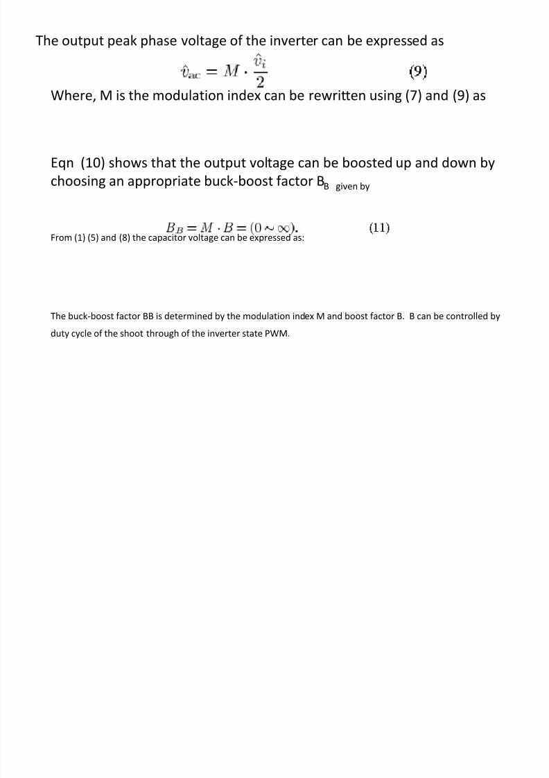
The output peak phase voltage of the inverter can be expressed as
Where, M is the modulation index can be rewritten using (7) and (9) as
Eqn (10) shows that the output voltage can be boosted up and down by
choosing an appropriate buck-boost factor BB given by
From (1) (5) and (8) the capacitor voltage can be expressed as:
The buck-boost factor BB is determined by the modulation index M and boost factor B. B can be controlled by
duty cycle of the shoot through of the inverter state PWM.

8/10/2019 Z Source Converter
http://slidepdf.com/reader/full/z-source-converter 12/12
•References:
•Fang Zheng Peng “Z-Source Inverter” IEEE trans. On Industry
Applications, Vol. 39, No.2 March/April 2003 pp.504-510.


![Single Switched Capacitor High Gain Boost Quasi-Z Source Converter · 2018-08-16 · 1[17], and the quasi-Z-Source converter in Fig -2 [32], the proposed converter is depicted in](https://img.pdfslide.us/doc/110x75/5f4d972568593756d475e483/single-switched-capacitor-high-gain-boost-quasi-z-source-converter-2018-08-16.jpg)


![Z SOURCE RESONANT CONVERTER FOR THE ELECTRIC VEHICLE ... · improve the efficiency over a wide input voltage and load variation[4]. Furthermore, a Z-source resonant converter (ZSRC)](https://img.pdfslide.us/doc/110x75/5d5ca46188c9931c5c8b4ef5/z-source-resonant-converter-for-the-electric-vehicle-improve-the-efficiency.jpg)