Embed Size (px)
Citation preview

Voltage Source Converter based Hybrid STATCOM for Reactive Power
Compensation in Utility Grid
Aditya Kumar Bhatt
A Thesis
in
The Department
of
Electrical and Computer Engineering
Presented in Partial Fulfillment of the Requirements for the
Degree of Master of Applied Science (Electrical Engineering and Computer Science) at
Concordia University
Montréal, Québec, Canada
February 2020
© Aditya Kumar Bhatt, 2020

CONCORDIA UNIVERSITY
SCHOOL OF GRADUATE STUDIES
This is to certify that the thesis prepared
By: Aditya Kumar Bhatt
Entitled: “Voltage Source Converter based Hybrid STATCOM for Reactive Power
Compensation in Utility Grid”
and submitted in partial fulfillment of the requirements for the degree of
Master of Applied Science
Complies with the regulations of this University and meets the accepted standards with
respect to originality and quality.
Signed by the final examining committee:
_________________________________________________
Dr. Yousef R. Shayan
Chair
_________________________________________________
Dr. Anjali Awasthi
Examiner, External
To the Program
_________________________________________________
Dr. Luiz A.C. Lopes
Examiner
_________________________________________________
Dr. Pragasen Pillay
Supervisor
Approved by: __________________________________________________
Dr. Yousef R. Shayan, Chair
Department of Electrical and Computer Engineering
20th February 2020
Dr. Amir Asif, Dean
Faculty of Engineering and
Computer Science

III
ABSTRACT
Voltage Source Converter based Hybrid STATCOM for Reactive Power
Compensation in Utility Grid
Aditya Kumar Bhatt
The availability of high voltage, high current and high-speed power electronic devices has led to
increase in popularity of several power electronic applications such as FACTS. A STATCOM is
one such power electronic converter, from the FACTS family, which can be used to improve the
power factor of a transmission line, maintain the connected bus at the required voltage level, etc.
In distribution power level, D-STATCOMs are used to achieve the same objectives. Several power
converter topologies have been proposed for STATCOMs and D-STATCOMs, ranging from a
standard two-level VSC based topology to a cascaded full-bridge based topology. The cascaded
full-bridge based topology might be suitable for high power STATCOM applications but might
not be the best option at the lower power level of a D-STATCOM. D-STATCOMs therefore often
use a standard two-level converter-based topology owing to cost constraints.
The research work presented in this thesis proposes a new power electronic topology which can
be used for D-STATCOM applications. This topology is essentially composed of multiple
cascaded h-bridge cells in each phase of a standard two-level converter. The two-level converter
provides bulk of the power output and operates at a low switching frequency, whereas the h-bridge
cell operates at a higher switching frequency and achieve power quality objectives. This research
work initially presents simulations to validate the proposed topology. Outer control is proposed to
operate the proposed topology as a D-STATCOM. Inner control loops are proposed to maintain
the DC-link voltage of the h-bridge cells. An experimental prototype of the proposed topology is
also developed. The results obtained from the proposed topology are compared with that obtained
from a standard two-level converter-based topology. It is shown that due to the h-bridge cell action
in the proposed topology, the obtained current THD is low in comparison to a standard two-level
VSC based topology being used as a D-STATCOM.

IV
Acknowledgements
First of all, I would like to express my deepest gratitude to the almighty for his grace and
bestowing his blessings upon me throughout this journey. I am thankful to my supervisor, Prof.
Pragasen Pillay, for giving me this opportunity.
The members of Power Electronics and Energy Research (PEER) became my small family in
no time. I am grateful to all my colleagues for helping in one or another way. To be specific, special
thanks to Amitkumar K.S. for solving all sorts of doubts numerous times. I have always looked
upon him in times of trouble. I would also like to thank my dear friend Sumeet Singh for his help
and support.
Last but not least, I am highly obliged to my family because they believed in my ambition and
stood by me to accomplish it. It would not be possible without my parents. Thank you for your
faith and encouragement.

V
Table of Contents
List of Figures ............................................................................................................................................. VII
List of Tables ............................................................................................................................................... IX
1. Introduction ........................................................................................................................................... 1
1.1 Reactive Power Compensation Overview:.................................................................................... 2
1.2 Overview of the two-level STATCOM ........................................................................................ 5
1.3 Motivation and Aim of the Project ............................................................................................... 5
1.4 Objectives ..................................................................................................................................... 6
1.5 Proposed Work and Model ........................................................................................................... 6
1.6 Thesis Outline ............................................................................................................................... 7
2. Literature Survey .................................................................................................................................. 9
2.1 Literature Review ................................................................................................................................ 9
2.2 Motivation of thesis .......................................................................................................................... 14
2.3 Concluding Remarks ......................................................................................................................... 15
3. Conventional Two-level STATCOM and Proposed Hybrid STATCOM ........................................... 16
3.1 Conventional Two-Level STATCOM .............................................................................................. 16
3.2 Proposed Hybrid STATCOM ........................................................................................................... 18
3.3 Controller Design of Conventional Two-Level STATCOM ............................................................ 20
3.5 Controller Design of Hybrid STATCOM and Harmonic Extraction ................................................ 27
3.6 Concluding Remarks ......................................................................................................................... 29
4. MATLAB Simulations and Results .................................................................................................... 30
4.1 Simulation Results and Discussion ................................................................................................... 30
4.2 Theoretical Analysis and Calculations .............................................................................................. 36
4.3 Harmonics Calculation ...................................................................................................................... 39
4.4 Concluding Remarks ......................................................................................................................... 44
5. Hardware Development and Experimental Results ............................................................................ 45
5.1 Results of Harmonic Cancellation for a Two-Level VSC Connected to Grid .................................. 47
A. DC Bus Voltage Build Up during Start-up .................................................................................... 48
B. STATCOM Startup (Injecting Reactive Power iq = 4 A) ............................................................... 48
C. Control Testing by iq Reversal ....................................................................................................... 50
D. STATCOM Output Waveform ...................................................................................................... 51
5.2 Concluding Remarks ......................................................................................................................... 55

VI
6. Conclusions and Future Scope ................................................................................................................ 56
6.1 Contribution and Conclusions ........................................................................................................... 56
6.2 Future Scope ..................................................................................................................................... 56
References ................................................................................................................................................... 58

VII
List of Figures
Fig. 1.1: An uncompensated transmission line operation and its phasor diagram ........................................ 4
Fig. 1.2: Operation of a series compensated transmission line and its phasor diagram ................................ 4
Fig. 1.3: Operation of a shunt compensated transmission line and its phasor diagram ................................ 4
Fig. 1.4: Proposed research schematic diagram ............................................................................................ 7
Fig. 2.1: Low-pass filter for the DC bus voltage reference to reduce transient in starting current. .............. 9
Fig. 2.2: Topology of a medium voltage level-based application [3] ......................................................... 11
Fig. 2.3: Configuration for medium voltage reactive power compensator [4]. ........................................... 12
Fig. 2.4: Hardware schematic of AMPEC [5]. ............................................................................................ 13
Fig. 2.5: VSC-HVDC transmission structure [6]. ....................................................................................... 14
Fig. 3.1: Conventional Two-Level STATCOM for lab test ........................................................................ 17
Fig. 3.2: Hybrid STATCOM: concept development ................................................................................... 18
Fig. 3.3: Hybrid STATCOM: designed converter [40] ............................................................................... 19
Fig. 3.4: Control diagram for the conventional STATCOM ....................................................................... 20
Fig. 3.5: Inner current control loop of a STATCOM .................................................................................. 21
Fig. 3.6: Plant transfer function for the inner current loop ......................................................................... 22
Fig. 3.7: Bode plot of inner current control loop with compensator and without compensator .................. 23
Fig. 3.8: Outer voltage control loop of a STATCOM ................................................................................. 24
Fig. 3.9: Bode plot of plant for outer voltage loop ..................................................................................... 25
Fig. 3.10: Bode plot of outer voltage control loop with compensator and without compensator ............... 26
Fig. 3.11: Control Philosophy of the Hybrid STATCOM: Wave-shaper cells ........................................... 28
Fig. 3.12: Control structure of DC link voltage control for the wave-shaper cells ..................................... 29
Fig. 4.1: Reactive power injection for control of Hybrid STATCOM ........................................................ 31
Fig. 4.2: Phase current, grid voltage and DC link voltage for the Hybrid STATCOM .............................. 32
Fig. 4.3: Harmonic spectrum of phase current for conventional STATCOM ............................................. 33
Fig. 4.4: Harmonic spectrum of phase current for Hybrid STATCOM ...................................................... 34
Fig. 4.5: Line Current of the conventional STATCOM operated at 3240 Hz switching frequency ........... 35
Fig. 4.6: Conventional Two-Level STATCOM .......................................................................................... 36
Fig. 4.7: Modulating voltage with a triangular voltage ............................................................................... 40
Fig. 4.8: Harmonics of three-phase Voltage Source Converter [39] ........................................................... 41
Fig. 4.9: Inverter line to line voltage waveform FFT analysis .................................................................... 43
Fig. 4.10: Phase current (𝐼𝑎) FFT analysis ................................................................................................. 43
Fig. 5.1: Without Harmonic Cancellation; CH1: Inverter terminal voltage, CH2: Injected voltage by series
H-bridge, CH3: line current, CH4: Real-time FFT of current waveform CH3 ........................................... 45
Fig. 5.2: With Harmonic Cancellation; CH1: Inverter terminal voltage, CH2: Injected voltage by series H-
bridge, CH3: line current, CH4: Real-time FFT of current waveform CH3 ............................................... 46
Fig. 5.3: DC voltage build-up, CH1: DC bus Voltage of STATCOM, CH2: Current waveform, CH3:
Voltage injected to the grid ......................................................................................................................... 48

VIII
Fig. 5.4: STATCOM startup (Injecting Reactive Power iq = 4 A peak) CH1: DC bus of STATCOM, CH2:
phase current ............................................................................................................................................... 49
Fig. 5.5: Harmonics analysis of the line current waveform (when iq = 4 A) .............................................. 50
Fig. 5.6: For iq Reversal (Reactive power flow control); mention the details of the waveforms ................ 51
Fig. 5.7: Current wave-shape before wave-shaper starts functioning, CH1: Pole voltage wrt DC bus
negative terminal, CH2: Line current, CH3: H-bridge injected voltage ..................................................... 52
Fig. 5.8: Harmonic spectrum of the hybrid STATCOM phase current before the wave-shaper functioning
.................................................................................................................................................................... 52
Fig. 5.9: Current wave-shape after the wave-shaper functioning, CH1: Pole voltage wrt DC bus negative
terminal, CH2: Line current, CH3: H-bridge injected voltage .................................................................... 53
Fig. 5.10: Harmonic spectrum of the hybrid STATCOM phase current after the wave-shaper functioning
.................................................................................................................................................................... 53

IX
List of Tables
Table 4.1: Harmonics of 3-phase Voltage Source Converter for 𝑚𝑓 = 9 .................................................. 40
Table 4.2: Generalized harmonics of 𝑣𝐴𝑜for a large 𝑚𝑓 [39] .................................................................... 41
Table 4.3: Simulated and calculated values of fundamental and harmonics components .......................... 42
Table 5.1: Details of hybrid STATCOM Lab Prototype............................................................................. 47
Table 5.2: Comparison of line current with and without harmonic cancellation ........................................ 54

1
1. Introduction
The advances in the power system network have brought great innovation to power
management technologies. Nowadays, the power system is no longer works locally and is
interconnected through one common centralized grid system. Across the country, the power is
generated from various resources and is shared in various forms over the grid. It is distributed
among remote areas and utilized by the remote consumers. The modern power system is a very
complex power system and every time it experiences threats regarding voltage instability leading
to voltage collapse. The voltage collapse is the process by which voltage instability leads to loss
of voltage in a significant part of a system. This occurs when the system is heavily loaded or not
able to maintain generation and transmission plants [1]. The main cause of voltage collapse is the
inability of the system to regulate the voltage with proper compensation of reactive power flows.
Hence, it became equally important to make the system sufficiently secure to withstand the various
contingencies occurring in the power system and adequate reactive power support to the system
so as to fulfill the requirement of Finest Quality Power (FQP). Thus, reactive power compensation
plays a crucial role in a Centralized Grid System (CGS) for maintaining FQP. Power electronics
are like medicine for every issue associated with the modern power system.
A Static Synchronous Compensator (STATCOM) is widely used for the reactive power
compensation in power system. It is a shunt device that is used in the transmission systems for
voltage regulation and reactive power compensation [2]. STATCOM allows for dynamic and quick
control of its AC voltage magnitude and phase, by a fast variation in the injected reactive power
to the grid ([2]-[4]). In practice, a STATCOM in a transmission grid-primarily is used to maintain
the voltage of the bus to which it is connected, at a constant value. Voltage regulation is normally
achieved with the help of automatic controllers and a voltage source converter (VSC) based
STATCOM can achieve a quick response time (within a few milliseconds) [2]-[4]. The majority
of the earlier installations of STATCOMs were either based on a two-level or three-level VSC [5]-
[6]. These VSC have a considerable amount of switching losses associated with them and also
introduce harmonics in the system and hence affect the power quality of the system [7]. To
overcome the issue of power quality standards the conventional two-level VSC based STATCOM
would either need to switch at higher frequencies or will need additional filters. Increasing the

2
switching frequency will increase the switching losses and adding a filter will affect the cost of the
STATCOM which is one of the major considerations for an optimal design. In this work, it is
proposed to include active wave shaping units along this the conventional two-level switching
frequency. The voltage harmonics generated by the two-level VSC are cancelled by the wave
shaping units which are connected in series with the 2-Level VSC based STATCOM. Since the
wave-shapers have a low power rating, hence the resulting losses will be very less than a
conventional two-level VSC based STATCOM working independently. All simulation and work
will be done in MATLAB and PSIM. This section presents an overview of reactive power
compensation and a brief explanation of the operation of a two-level STATCOM.
1.1 Reactive Power Compensation Overview:
Static power compensators (STATCOMs) are representative of fast-acting static synchronous
compensators in the Flexible AC Transmission Systems (FACTS) family [8-16]. They are used in
power systems especially in transmission and distribution systems for reactive power control. The
main objectives of reactive power compensation are as follow:
Voltage regulation
System stability
Loss reduction (losses associated with the system)
Better utilization of machines connected to the system
The stability limits of the power system are affected by the transmission lines impedance and the
consumption of the reactive power by AC machines [17-22]. The voltage drop across the
transmission lines has to be compensated by supplying higher voltage from the source. This causes
more stress on the overall system and is unpredictable because the voltage drop is not constant. To
solve this problem, capacitors were used to overcome the inductive effect of transmission lines
and large motors used in industries. But this method is not dynamic and therefore is not a
reasonable solution.

3
New methods have been developed in recent years, in particular, dynamic methods using better
devices. The compensation is dynamic and therefore more effective. One of the means of achieving
this is with the help of a STATCOM [23-34].
The majority of the loads in the power systems are inductive. They consume the reactive power
for their operation. By regulating the reactive power supplied near the load, the line current can be
minimized. This reduction in line current reduces, as a result, the losses through the power lines
and improves the voltage regulation across the load terminals. The reactive power regulation can
be done in three ways: through a voltage source, a current source or a capacitor. STATCOMs acts
as a controllable current source.
The compensation techniques, in general, can be grouped into two main categories, namely; shunt
compensation and series compensation. The series and shunt compensation techniques can be
explained with the help of the phasor diagrams shown in fig. 1.1 to fig 1.3. In a series compensator,
the compensation system is in series with the load. There are quite a few advantages of series
compensation such as reduced voltage rating of the compensator.
Shunt compensation is another means of achieving reactive power compensation. In shunt
compensation, the compensator is connected in shunt with the transmission system. Therefore, the
voltage rating of the compensator is quite high, however the current rating is lower, depending on
the reactive power that needs to be compensated.
Some of the features/ advantages of shunt compensation are listed as follows:
• A shunt compensator is connected in parallel with the circuit. Therefore, even its failure would
not cause the entire system to fail, and the rest of the circuit would still be working.
• The compensation provided by the STATCOM can be controlled without any dependency on
the system voltage. This is an important advantage and is not true in the case of other
compensation techniques such as a fixed capacitor.
• The shunt compensator can not only provide the desired reactive power but at the same time
can also cancel harmonics in the system by acting as an active filter.

4
Fig. 1.1: An uncompensated transmission line operation and its phasor diagram
Fig. 1.2: Operation of a series compensated transmission line and its phasor diagram
Fig. 1.3: Operation of a shunt compensated transmission line and its phasor diagram
5
1.2 Overview of the two-level STATCOM
A two-level converter is typically used in a conventional STATCOM. It is usually switched at
a higher frequency around 1 kHz to 5 kHz and might require additional filters to limit the current
THD within bounds. The 𝑑𝑣
𝑑𝑡 of a two-level STATCOM is very high and therefore, reflects higher
stress on the AC filters used if any. The main drawback of this type of STATCOM is its higher
switching losses associated due to its high switching frequency requirement and will be discussed
later in the thesis. Also, for high-power applications, the switching frequency of the two-level
inverter is very much restricted due to the limitation of the available power semiconductor devices.
This introduces an additional problem relating to the current waveform quality.
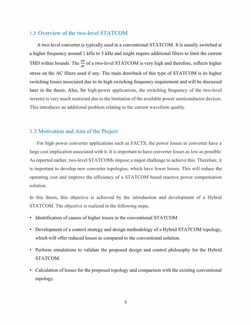
1.3 Motivation and Aim of the Project
For high power converter applications such as FACTS, the power losses in converter have a
large cost implication associated with it. It is important to have converter losses as low as possible.
As reported earlier, two-level STATCOMs impose a major challenge to achieve this. Therefore, it
is important to develop new converter topologies, which have lower losses. This will reduce the
operating cost and improve the efficiency of a STATCOM based reactive power compensation
solution.
In this thesis, this objective is achieved by the introduction and development of a Hybrid
STATCOM. The objective is realized in the following steps;
• Identification of causes of higher losses in the conventional STATCOM
• Development of a control strategy and design methodology of a Hybrid STATCOM topology,
which will offer reduced losses as compared to the conventional solution.
• Perform simulations to validate the proposed design and control philosophy for the Hybrid
STATCOM.
• Calculation of losses for the proposed topology and comparison with the existing conventional
topology.

6
1.4 Objectives
The objectives of this thesis are as follows:
1) Identification for causes of higher losses in conventional STATCOM
2) Development of a control philosophy and design methodology of a hybrid STATCOM topology
which will have lower losses as compared to the conventional STATCOM.
3) Perform simulations to validate the proposed design and control philosophy for the hybrid
STATCOM.
1.5 Proposed Work and Model
In this thesis, a hybrid STATCOM is introduced and proposed for reactive power
compensation.
A hybrid switching STATCOM consists of a two-level Voltage Source Converter [35-38] and
series H-bridges acting as series wave-shaper. A schematic diagram of basic hybrid switching
STATCOM is shown in Fig.1.4.
The two-level VSC based STATCOM and series-connected wave-shaper units together eliminate
harmonics, which are injected by the conventional two-level VSC based STATCOM for switching
at low frequency. When the STATCOM generates harmonics, after 2-4 cycles of current waveform
the wave-shaper units start generating the harmonics voltage, which is injected in series and 180
degrees phase-shifted with the harmonic’s voltage by STATCOM such that the low order
harmonics will be cancelled out. The phase-angle control will assist the STATCOM to cover the
reactive power demand and voltage regulation.
In order to get the hybrid system performance, individual components need to be modelled first
and then combination will be evaluated to meet the expectation.

7
Fig. 1.4: Proposed research schematic diagram
As a first step, the simulation of STATCOM (i.e. as Front-End Converter) is conducted in the
MATLAB environment for the reactive power compensation including various disturbances in the
power system. Then, further in the next stage the H Bridges wave-shaper units are included to
reduce the total harmonic distortion (THD).
The prime advantage of incorporating the wave-shaper is the reduction of the THD which is
created by the two-level VSC based STATCOM. There is a rich selection of the approaches and
several advances have been made and will be reviewed in the upcoming Chapters.
The modelling, simulations and related programming are carried out in MATLAB, due to the
computational competency and inbuilt function database, for validation and analysis. Testing is
done using the OPAL-RT controller module and various other parts, which are fabricated in Power
Electronics and Energy Research laboratory at Concordia University.
1.6 Thesis Outline
The thesis is organized into 6 chapters, to understand the operation of STATCOM, proposed
hybrid STATCOM, its operation and results along with detailed analysis and calculations. There
are two main parts of the proposed hybrid STATCOM i.e. Conventional Two Level STATCOM
and H-Bridge wave-shapers and both the parts are discussed in detail. The thesis outline are as
follows:

8
Chapter 1: Introduction contains the brief introduction of the conventional two-level STATCOM
used in the power system for reactive power compensation as well as series and shunt
compensation. This chapter also briefly introduces H-Bridges, which are used as wave-shaping
units later in the thesis.
Chapter 2: Literature Review reports the survey of the conventional methodologies reported in
the field related to the proposed model.
Chapter 3: Conventional Two-Level STATCOM and Proposed Hybrid STATCOM discuss
the requirements of two-level STATCOM, its design, and component selection of STATCOM
along with its basic mathematical model. This chapter also contains the introduction to harmonic
cancellation technique, active power filters its classification and the PWM switching scheme of
the devices. Single-phase H-Bridge converter has also been discussed in detail along with the
discussion on the sinusoidal pulse with modulation (SPWM).
Chapter 4: MATLAB/Simulation and Results contains the complete Simulink model of the
proposed model. Parameters used for the simulation of various parts are also shown in this chapter.
The simulation results of the model are included and discussed.
Chapter 5: Hardware Development and Experimental Results contains the experimental results
of the proposed hybrid STATCOM using OPAL-RT. Hardware development is discussed in detail.
The comparison of results with respect to switching loss for the topology of Hybrid two-level
Voltage Source Converter as explained.
Chapter 6: Conclusion and Future Scope gives the conclusion of the contribution of the thesis
and research done through the proposal of Hybrid STATCOM for reactive power compensation
along with possibilities of future scope of its extension.

9
2. Literature Survey
Several researchers working in the area of STATCOM control have contributed to conventional
vector control strategies. It is observed that the STATCOM using the conventional control
strategies produces a lot of harmonics that affect stability, reliability and efficiency of the power
system. Hence, it becomes mandatory to investigate reactive power control using STATCOM.
There are various control strategies for control of STATCOM are still under investigation. A few
relevant recent control strategies are discussed as follows:
2.1 Literature Review
In [1] authors have implemented a vector control technique for a Front-End Converter (FEC) of a
250-kVA rating. It was observed that for a high-power front-end converter (FEC) starting current
transient is considerably high as the designed value of the filter inductor was very low. In order to
limit the transient, an algorithm has been proposed as shown in Fig. 2.1.
Fig. 2.1: Low-pass filter for the DC bus voltage reference to reduce transient in starting current.
The reference value of a DC bus voltage (Vdc) is ramped up from initial value to its final value for
a particular time period. The time duration is large enough then its voltage loop time constant.
First, the reference signal of a DC bus voltage is sent to a low-pass filter and later to a controller.
Due to filter in the path, the rate of change of a reference signal of a voltage controller becomes
slow and the voltage controller is able to track reference voltage more accurately. Therefore, the
error gets reduced during starting, which leads to low starting current. But due to the addition of a
low-pass filter in a path, the response time of a front-end converter starts lagging with respect to
its DC bus reference voltage. During starting, the reactive power reference value is set at zero
therefore the transient in starting current gets reduced. The DC bus voltage is pre-charged and

10
when the unit vector generation reaches its steady-state value, the control procedure is executed,
and the low-pass filter is added in the DC bus voltage reference path. The proposed work by author
improve the results and mitigated the starting transient current inline side converter.
STATCOM four quadrant operations and its control have been discussed in various research
publications. The Electric Power Research Institute (EPRI), USA has conducted numerous
researches on high power STATCOM using GTO based Voltage Source Converters (VSCs) and
prototyped STATCOM projects in collaboration with a number of institutes and organizations. In
research publications, controllers are termed as Advanced Static VAR Compensator (ASVC),
Advanced Static VAR Generator (ASVG), and Static VAR generator (SVG), Static Condenser
(STATCON), Synchronous Solid-state VAR Compensator (SSVC) and Static synchronous
compensator (SSC). Power industries such as ABB, GE, Toshiba, Mitsubishi etc. has done R&D
and developed STATCOM based high-voltage transmission system along with Unified Power
Flow Controller (UPFC). In the past decades, numerous topologies and configurations of the
converter, its control strategy and algorithm, different switching techniques have been proposed
and reported in the literature for grid distribution and transmission network. In [2] STATCOM
controllers have been reviewed in detail for new research potential in the area. The idea of voltage
re-injection in the DC link of the STATCOM topology working at a fundamental switching
frequency will reduce the harmonics and improves the functionality and performance with minimal
usage of solid-state devices. It was also concluded that among various multi-level converter
circuits, the three-level topology is the most practical one. Beyond three-level converter topology,
the controller for voltage balance across the DC capacitors, which are used as an energy storage
device, is not easy. Therefore, higher level topologies are not practically used. Another scope of
research is to improve controller to handle system dynamics when faults occur either asymmetrical
or symmetrical in the high-voltage transmission systems. In order to improve this, algorithms such
as fuzzy logic can be employed.
In [3] an open-loop control strategy has been proposed for a Voltage Source Inverter (VSI) for
high-power applications. The inverter is prototyped for laboratory testing using high-power and
low switching solid-state devices i.e. Integrated Gate Commutated Thyristors (IGCTs). It is
observed that series compensators are IGBT based converters and operate at high-switching
frequencies at low DC bus voltage. These compensators will generate the desired harmonic voltage

11
to realize a sinusoidal output voltage. Numerous compensators are connected in series for medium-
voltage applications as shown in Fig. 2.2
Fig. 2.2: Topology of a medium voltage level-based application [3]
Here, each compensator will compensate or eliminate the level of a particular harmonic. When the
order of harmonics in the system increases, the level of the required DC bus voltage is reduced. It
helps to use a higher switching frequency for the higher order of harmonics compensators. In the
proposed technique, it is observed that there is no need for any external DC source or closed-loop
controller. Therefore, the DC bus voltage remains charged by the active power available at the
harmonic’s frequencies. For other applications such as variable speed drives, the output voltage
amplitude is controlled by maintaining the DC bus voltage of the inverter. For Static Synchronous
Compensator (SSC) applications, DC bus voltage can be maintained by receiving a low magnitude
of active power at the fundamental frequency from the grid.
In [4] a sinusoidal hybrid converter configuration has been proposed for the medium-voltage
reactive power compensator as shown in Fig. 2.3

12
Fig. 2.3: Configuration for medium voltage reactive power compensator [4].
The main inverter that supplies the reactive power is named as shunt converter. It is a square-wave
inverter and is responsible for generating fundamental reactive current. As the switching losses for
this shunt inverter is low; hence, high voltage switching devices such a GTO and IGCT can be
used. In order to eliminate harmonics voltage from the output voltage of the hybrid converter,
various single-phase converters are connected in series. Two different methods have been
proposed for open loop switching techniques. In the first method, the SPWM technique is used
with a modulation index of unity and the reference voltage is in phase with the inverter harmonic
voltage. In the second method, square waves are in phase with the harmonic’s voltages,
respectively of the series cells. It has been observed that the DC bus voltage of the series cells
reaches the desired voltage level in both the proposed methodologies. Therefore, the harmonics
are eliminated by the series cells and the resultant output voltages of the converter are sinusoidal.
There is no need for sensing the DC bus voltages for its controller. The second method allows low
switching frequency for its cells connected in series and hence increases in the voltage rating of
these cells. Thus, it helps to achieve the medium voltage operation of the converter for reactive
power compensator. By varying the DC bus voltage of the shunt converter, fundamental reactive
power is controlled and to vary the DC voltage, the phase angle between the shunt converter and
the grid voltage level have to be controlled. However, the rate of variation of the reactive current

13
cannot be achieved quickly. An alternate technique to mitigate the harmonics generated by a
square-wave inverter can be achieved by implementing active power filters in a shunt connection.
This active power filter connected in shunt fashion can mitigate current harmonics whereas the
proposed H-bridge which is connected in series reduces voltage harmonics. The proposed
configuration is for medium-voltage applications and the device voltage and current ratings will
be a concern in their selection.
In [5] PWM based voltage source inverter has been simulated with two different IGBT devices
modulated with different modulation schemes and power losses have been compared. The Punch
Through (PT) technology is introduced by Toshiba, whereas the Non-Punch Through (NPT)
technology is introduced by Siemens. Both technologies have been investigated. Later, the
modulation techniques are compared with sinusoidal modulation having third harmonics and a
60 ° non-active phase bridge modulation. The loss model discussed in the literature is based on
the experimental results and then the devices are characterized using Advanced Measurement
Power Electronics Components and Circuits (AMPEC) as shown in Fig. 2.4.
Fig. 2.4: Hardware schematic of AMPEC [5].

14
It was observed that 60° PWM based technique has reduced switching and hence, the general
losses are less compared to the sinusoidal modulation added with a third harmonics. The NPT
devices are suitable for higher switching frequencies whereas PT devices are more suitable for
lower switching frequencies if the gate resistance used is of lower value. The PT devices are better
when the load current is high. It was also observed through simulation that the losses in the inverter
are proportional to the load current, switching frequency and modulation index.
In [6] a mathematical approach is introduced to analyze the losses for the two-level and three-level
voltage source converter based HVDC transmission systems as shown in Fig. 2.5 and later the
results are validated through software simulation. The obtained results show that due to the usage
of a neutral point clamped three-level converter, the conversion losses are reduced since the
switching frequency of the devices is reduced to half compared to that of a two-level converter
configuration. The conversion losses in the two-level converter are around 63.74 % of the total
losses whereas for the three-level converter the conversion losses are around 55.5 %. These losses
can further be reduced if high voltage levels are used.
Fig. 2.5: VSC-HVDC transmission structure [6].
2.2 Motivation of thesis
In this thesis, in order to reduce switching losses in 2-level VSC, the low switching frequency
around 540 Hz is used; however, the low switching frequency will introduce certain low order
harmonics in the system which requires a bulky filter. In order to avoid the bulky inductor, it is
desired to cancel the dominating harmonics, which are close to the fundamental frequency.

15
Among the various research strategies discussed so far, the wave-shaper units are found to be the
most prominent technique, which can be used to cancel out the low order harmonics which are
generated during the low-frequency operation of a 2 level VSC. Since these wave-shaper units
have low DC bus value; therefore, the switching losses will also be less in the system. It developed
the further motivation to start the investigation and analyze a Hybrid STATCOM, which is a
combination of a two-level VSC with wave-shaper units targeting specific harmonics in order to
reduce the semiconductor device losses and the filter size. Therefore, the novelty of the proposed
technique is on-line voltage harmonic cancellation by the wave-shaper units (unlike the proposal
in [3] and [4]).
2.3 Concluding Remarks
A literature survey is presented in the area of STATCOM controls which have contributed to
conventional vector control strategies. It is observed that the STATCOM using the conventional
control strategies produces a lot of harmonics that affect stability, reliability and efficiency of the
power system. Hence, it becomes mandatory to investigate reactive power control using
STATCOM. There are various control strategies for control of STATCOM are still under
investigation.

16
3. Conventional Two-level STATCOM and Proposed Hybrid STATCOM
A Static synchronous Compensator (STATCOM) is widely used for reactive power compensation
in the power system. It is a shunt connected system, which is used in the transmission system for
voltage regulation and reactive power compensation. STATCOM allows for dynamic and quick
control of its AC voltage magnitude and phase by a fast variation in the injected reactive power to
the grid. In practice, a STATCOM in a transmission grid is primarily used to maintain the voltage
at the bus to which it is connected, at constant. Voltage regulation is normally achieved with the
help of automatic controllers and a voltage source converter (VSC) based STATCOM can achieve
a quick response time typically a few milliseconds.
A STATCOM comprises of a 3-phase inverter (usually SPWM modulated) using SCRs,
MOSFETs or IGBTs, a DC capacitor that maintains the DC bus voltage for the inverter, a link
reactor which is used for linking the inverter output to the AC supply, filter to absorb the high-
frequency components due to the PWM inverter. The generated voltage is further synchronized
with the AC supply and depending on the phase of the current, either active or reactive power is
supplied or absorbed.
3.1 Conventional Two-Level STATCOM
A STATCOM comprises of a voltage source inverter (VSI) that produces AC voltage from DC
voltage and has the capability to transfer power in either direction. VSCs are the building blocks
of HVDC and FACTS in the present age. There are two types of VSCs, the first one is square wave
inverter with GTO as the switching device and the second one is PWM inverter with IGBT. The
two-level converter topology, as shown in Fig. 3.1, is conventionally used in reactive power
compensation in the modern power system as STATCOM. The control strategies used by these
inverters to convert DC voltage into 3-phase AC voltage are based on PWM. In PWM techniques,
an inverter is controlled through ON/OFF time control the inverter’s switching devices. This
topology has six IGBTs with anti-parallel diodes and has the highest switch utilization and low
conduction loss among all 3-phase inverters [39]

17
Fig. 3.1: Conventional Two-Level STATCOM for lab test
Inductive reactance is connected between the grid and the inverter. The sources are bound together
by using this inductor in series that also acts as a filter. The flow of active and reactive power takes
place through this inductance. It also helps to neutralize the harmonics at the point of common
coupling (PCC). The harmonic filter may be active or passive. The function of the filter is to further
reduce harmonics generated by two-level VSCs.
Hence, before implementing grid-connected STATCOM operation, the initial step is to test the
two-level VSC as an inverter feeding different 3-phase loads such as R-L Load, pure inductive (L)
load and at no load. Therefore, real-time simulation results of a two-level inverter have been done.
The real-time simulation and hardware-in-loop testing (HIL) is done by using real-time OPAL-RT
simulator (OP45610). Modelling and simulation are done in MATLAB.
Simulation is done by selecting the IGBT/diode module in the family of the available block in
MATLAB. For calculating the power losses, the waveforms obtained from MATLAB-Simulink
and the datasheet parameters of the devices will be used. The MATLAB model integrates the
components required for different voltage levels of the inverter (multilevel inverter) and shows the
power losses. An ambient for temperature is assumed as room temperature and for calculation of
losses, a worst-case temperature of 125 degrees Celsius is chosen.

18
3.2 Proposed Hybrid STATCOM
The motivation and objective behind proposing a Hybrid STATCOM are to find means of reducing
the switching frequency of the two-level converter while maintaining the same quality of the
current waveform. A simple representation of how the Hybrid STATCOM works is shown in Fig.
3.2. As can be seen, the wave shaping units are H-Bridge cells connected in series with the main
conventional two-level converter. These H-bridge wave-shaper cells basically have the objective
of cancelling the harmonics generated by the two-level converter that is modulated at a lower-
switching frequency. An exaggerated case of the two-level converter of the Hybrid STATCOM
switching at a fundamental frequency and the wave-shaper cells switching cancelling the generated
harmonics is shown in Fig. 3.3.
Fig. 3.2: Hybrid STATCOM: concept development
The schematic of the proposed converter design and analysis is shown in Fig. 3.3. As can be seen
from Fig. 3.2, two H-bridge cells are considered per phase in the circuit. Optimization of the
number of switches for H-bridges is not done. It is chosen in order to validate the concept of Hybrid
STATCOM.

19
Fig. 3.3: Hybrid STATCOM: designed converter [40]
The switching frequency of the two-level converter in Hybrid STATCOM is reduced to 540 Hz.
This is done to ensure that the switching losses reduce significantly. The wave-shaper cells, on the
other hand, have the following objective;
a) Cell 1: Designed to cancel the 5th and the 7th harmonic, switching at 5000 Hz
b) Cell 2: Designed to cancel the 11th and the 13th harmonic, switching at 5000 Hz
c) Cell 3: Designed to cancel the 17th and the 19th harmonic switching at 5000 Hz
The voltage rating of the wave-shaper cells depends on the amplitude of the corresponding
harmonics generated by the two-level converter. Based on the simulation and FFT analysis of the
resultant voltage waveform of the two-level converter with dc bus voltage of 400 V switching at
540 Hz, it is observed that a cell voltage rating of around 50 Volts, for all the cells will be sufficient
to cancel the corresponding harmonics.
Therefore, even though the switching frequency of the wave-shaper cells is quite high, since the
voltage across the devices is much lesser, i.e., at 50 Volts instead of 400 Volts as for main
STATCOM, the switching losses will not be very high. This will be validated in the upcoming
sections to follow on the loss calculation.

20
3.3 Controller Design of Conventional Two-Level STATCOM
The conventional STATCOM control is well established and reported [1]. The idea is to control
the inverter output voltage magnitude to inject the required reactive power. For this purpose, all
quantities are converted to the rotating reference frame the signal to DC quantities. Once converted
to DC, these voltages and currents are compared with their corresponding reference values with a
PI controller, thus simplifying the controller implementation and design.
The steps to design a controller for the STATCOM are as follows,
• STEP 1: Identifying the rotating reference frame and designing PLL (Phase lock loop) for PCC
voltage (fixed).
• STEP 2: Measured 3-phase currents are converted to fix DC- Quantities by using abc to dq0
transformation.
• STEP 3: For a STATCOM, assuming that the PLL locks the grid voltage vector on the d-axis,
the d-axis current will correspond to the converter losses and the q-axis current will correspond
to the reactive power that needs to be injected.
Fig. 3.4: Control diagram for the conventional STATCOM
So, in this topology, three PI controllers are used to control the various inputs as shown in Fig. 3.4.
Firstly, the inner current control loop for the STATCOM. Secondly, the outer voltage loop for the
STATCOM. The bandwidths of these controllers are chosen based on the speed of the dynamic
response of every single controller.

21
Transfer Function of Inner Current Control Loop
The transfer function of the plant as shown in Fig. 3.5 is given by,
𝐺(𝑠) =𝐼𝑑,𝑞(𝑠)
𝐸𝑑𝑞(𝑠)=
1/𝑅
1 + 𝑠𝜏 (3.1)
The design of the inner current loop depends on the phase reactor and the associated resistance
values.
Fig. 3.5: Inner current control loop of a STATCOM
The current loop has a faster response than the voltage control loop. The inner current loop
bandwidth of STATCOM is chosen as fx = 30Hz (around 10 % of switching frequency) and the
switching frequency fsw considered in this work is 540 Hz. The nominal parameters are chosen as:
R = 1 mΩ
L = 5 mH
𝜏 = L/R = 0.005/0.001 = 5
The crossover frequency is chosen as 30Hz and PM =60 degree
𝐺𝑝(𝑆) =1/0.001
1 + 𝑠(0.005/0.001) (3.2)
𝐺𝑝(𝑗𝑤𝑥) =1000
1 + 5𝑠 3.3)

22
|𝐺𝑝(𝑗𝑤𝑥)| = 1.429 𝑑𝐵 𝜑𝑝 = 89.930
The bode-plot of current loop transfer function is as shown in Fig. 3.6
Fig. 3.6: Plant transfer function for the inner current loop
The phase margin of 59.8 deg is obtained at f=30 Hz.
𝐾𝑃 = 0.84
𝐾𝐼 = 83.31
𝐶𝑜𝑛𝑡𝑟𝑜𝑙𝑙𝑒𝑟 𝑇𝑟𝑎𝑛𝑠𝑓𝑒𝑟 𝐹𝑢𝑛𝑐𝑡𝑖𝑜𝑛 = 𝐾𝑃 + 𝐾𝐼
𝑠 (3.4)
𝜏 =𝑘𝑝
𝑘𝑖 𝑘𝑖 =
𝑘𝑝
𝜏, 𝑘𝑝 = 0.84 𝑘𝑖 = 83.31

23
Fig. 3.7: Bode plot of inner current control loop with compensator and without compensator

24
As shown in the Fig. 3.7 the phase margin of 60 degree is obtained at the crossover frequency of
30 Hz approximately.
Transfer Function of Outer Voltage Control Loop
Fig. 3.8: Outer voltage control loop of a STATCOM
The voltage control loop as shown in Fig. 3.8 is slower than the current control loop; therefore, the
bandwidth of the voltage control loop must be lesser than current control loop. The voltage control
loop has been designed based on the current control loop of the STATCOM. The plant transfer
function is given as
𝐺(𝑠) =𝑉𝑐(𝑠)
𝐼𝑞(𝑠)=
𝑣
𝑖=
1.5𝑉𝑞
𝑠𝐶𝑉𝑐𝑜 (3.5)
The bandwidth is chosen as fx = 5 Hz and the phase margin PM = 60 degree.
𝐺(𝑠) =1.5(169.83)
𝑠(3000𝜇𝐹)(400) (3.6)
𝐺(𝑠) =254.745
1.2𝑠 (3.7)
|𝐺𝑝(𝑗𝑤𝑥)| = −16.58 𝑑𝐵
𝜑𝑝 = −900
The bode-plot of voltage control loop transfer function is shown in Fig. 3.9

25
Fig. 3.9: Bode plot of plant for outer voltage loop
The controller type PI is chosen, and its parameters are following:
𝐺𝑝𝑖 = 𝐾𝑃 +𝐾𝐼
𝑠 (3.8)
The voltage control loop has been designed based on the current loop of STATCOM with the
following values given as:
𝑉𝑞 =208
√3∗ √2 = 169.83
𝑉𝑐𝑜 = 400 𝑣𝑜𝑙𝑡𝑠
The transfer function can be given by:
𝐺(𝑠) =𝑉𝑐(𝑠)
𝐼𝑞(𝑠)=
𝑣
𝑖=
1.5𝑉𝑞
𝑠𝐶𝑉𝑐𝑜 (3.9)
𝐺(𝑠) =1.5(169.83)
𝑠(3000𝜇𝐹)(400)=
254.745
1.2𝑠 (3.10)

26
The phase margin of 61.8 deg is obtained at f = 5 Hz.
𝐾𝑃 = 0.148
𝐾𝐼 = 2.68
Fig. 3.10: Bode plot of outer voltage control loop with compensator and without compensator

27
As shown in Fig. 3.10, the phase margin of 60 degrees is obtained at the crossover frequency of 5
Hz. However, the switching frequency is 540 Hz.
Assumptions and Component Selection
1. The direction of the power flow is assumed from the converter towards the grid for the
entire analysis.
2. The inductance value of 5 mH is chosen based on the availability in the lab.
3. The capacitance value calculated from the energy balance equation from AC to DC side is
3000 uF and the value of ripple current is 21 A for the safer operation.
4. The IGBT is rated at 1200V/5A. However, the safer voltage is around nearly 600 V.
5. The DC link voltage used in the simulation is 400 V, so for the safer operation a 50 %
voltage overshoot is considered.
6. Optimization of the number of switches for H-bridges is not done, it is chosen to validate
the concept.
7. The working temperature is assumed as room temperature.
3.5 Controller Design of Hybrid STATCOM and Harmonic Extraction
Converter structures with series wave-shaper circuits, such as the Hybrid STATCOM have been
reported in the literature. The novelty of the proposed control scheme is the online harmonic
cancellation with the help of wave-shaper circuits. This is achieved by multiple PLLs at the pole
voltage output of the two-level converter. First, the PLLs are locked at the corresponding
harmonics to be extracted such that the corresponding d and q axis voltages are DC quantities.
Then, with the help of low pass filters harmonics extracted. These harmonic voltages are applied
as the desired output voltages (modulation references) for the three wave-shaper cells. The control
philosophy of the Hybrid STATCOM and the wave-shaper circuits is shown in Fig. 3.11. A brief
explanation of the same is presented below.

28
Fig. 3.11: Control Philosophy of the Hybrid STATCOM: Wave-shaper cells
The function of extracting the 5th, 7th, 11th, 13th, 17th and 19th harmonics is done with the help of
multiple PLLs at the pole voltage output of the two-level converter. These PLLs are locked at the
corresponding harmonics to be extracted such that the corresponding d and q axis voltages are DC
quantities. Then with the help of low pass filters, these harmonics can be extracted easily. These
harmonic voltages are applied as the desired output voltages (modulation references) for the three
wave-shaper cells.
It is important to note here that there is no DC voltage source at the DC link of the wave-shapers,
just as in the case of the two-level converter. The two-level converter of the Hybrid STATCOM
has the same control as shown for the conventional STATCOM to maintain the DC link voltage at
a fixed value and inject the required amount of reactive power. The wave-shaper cells in similar
lines need to maintain their DC links at a constant value so that they can apply the required
harmonic voltages and cancel relevant harmonics introduced by the two-level converter. The
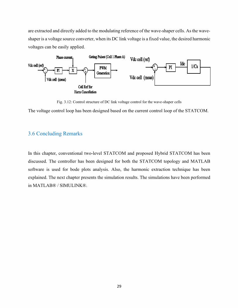
control structure for the DC link voltage control of the wave-shaper cells is shown in Fig. 3.12.
The controller ensures that independent of the current direction, the capacitance can be charged or
discharged as required. The plant transfer function is quite simple; it is an integrator at the origin.
The controller gains can be calculated based on this plant to achieve high bandwidth. The values
of kp and ki for the controllers are calculated as 1 and 10, respectively. The harmonics to be added
29
are extracted and directly added to the modulating reference of the wave-shaper cells. As the wave-
shaper is a voltage source converter, when its DC link voltage is a fixed value, the desired harmonic
voltages can be easily applied.
Fig. 3.12: Control structure of DC link voltage control for the wave-shaper cells
The voltage control loop has been designed based on the current control loop of the STATCOM.
3.6 Concluding Remarks
In this chapter, conventional two-level STATCOM and proposed Hybrid STATCOM has been
discussed. The controller has been designed for both the STATCOM topology and MATLAB
software is used for bode plots analysis. Also, the harmonic extraction technique has been
explained. The next chapter presents the simulation results. The simulations have been performed
in MATLAB® / SIMULINK®.
30
4. MATLAB Simulations and Results
The prime advantage of incorporating active wave-shaper is in the reduction of the current THD
introduced by two-level VSC based STATCOM. The two-level VSC based STATCOM together
with series active wave-shaper, cancels the harmonics injected in the system. When STATCOM
introduces harmonics during its operation after 2-4 cycles the wave-shaper units are activated and
start cancelling them by injecting voltage equal in magnitude and the 180-degree phase shifted.
Voltage sensors in each phase are used to sense pole voltage and the signals are further sent to
harmonic extractor units. The phase angle control will assist the STATCOM to cover the reactive
power demand and voltage regulation until the shortage is depleted. In order to get the hybrid
STATCOM system performance, individual components need to be modelled first and then
combination will be evaluated to meet the expectation. Hence in this chapter the simulation of
hybrid STATCOM is presented.
4.1 Simulation Results and Discussion
Most of the simulation/programming is carried out in MATLAB due to its computational
competence and inbuilt data function database. Further testing is carried out using the OPAL-RT
controller module (OP4510) and various other parts, which are fabricated in PEER Lab at
Concordia University. Fig. 4.1 shows the reactive power injection control of Hybrid STATCOM.

31
Fig. 4.1: Reactive power injection for control of Hybrid STATCOM

32
Fig. 4.2: Phase current, grid voltage and DC link voltage for the Hybrid STATCOM
Fig. 4.2 shows the DC link voltage and the phase current of the conventional STATCOM. As
explained earlier for the STATCOM, the voltage reference is 400 V. The control for the
STATCOM begins at around 0 seconds. There can be a transient change noticed at this time in
both the current and the voltage waveforms. The DC link voltage stabilized at around 0.2 seconds.
As mentioned earlier, the reactive power reference starts ramping at around 0. Until then the phase

33
current is at a very small value but reaches the rated current of around 13.87 A after 0.4 seconds.
It should be noted here that during the entire simulation, the DC link voltage of the capacitor is
maintained at 400 V.
Fig. 4.3: Harmonic spectrum of phase current for conventional STATCOM
Fig. 4.3 shows the harmonic current of the phase current for the conventional STATCOM. As can
be seen, the current THD is 35.09 % due to the choice of 540 Hz as the switching frequency. From
the spectrum of the phase current in Fig. 4.3, the harmonic sidebands occur at and around 540 Hz.
It should be noted that there are a few lower-order harmonics. These can be attributed to the large
dead-time (around 5 𝜇𝑠) used when the simulation results were captured. It is also clear that the
peak phase current is at its rated value around 20 A. It is shown in Fig. 4.2 that during 0.2 to 0.4
seconds, Hybrid STATCOM works as a conventional STATCOM and the wave-shaper cells are
bypassed. At 0.6 seconds, the wave-shaper cells are activated and the reactive power compensation

34
continues. It should be noted that the wave-shaper cells are not injecting any reactive power but
the harmonic cancellation.
Fig. 4.2 clearly shows the impact of the wave-shaper circuits in terms of current waveform
improvement. As mentioned earlier, the wave-shaper is bypassed until 0.4 seconds into the
simulation. At around 0.6 seconds, the wave-shaper circuit starts filtering the harmonics injected
by the two-level converter of the Hybrid STATCOM. It should be pointed out here that the two-
level converter is switching at a much lower frequency of 540 Hz, as can be noticed from the poor
current waveform as shown in Fig. 4.3. At 0.6 seconds when the wave-shaper circuit starts filtering,
the current waveform improves significantly as shown in Fig. 4.4
Fig. 4.4: Harmonic spectrum of phase current for Hybrid STATCOM
Fig. 4.4 presents clearly the functioning of the wave-shaper circuit in terms of the measured
harmonic spectrum. As can be seen, in the first harmonic plot in Fig. 4.3, the THD is quite poor

35
(35.09 %). This is the period of the simulation where the wave-shaper is bypassed and it is just the
two-level converter switching at a low switching frequency of 540 Hz feeding reactive power to
the grid. It is clear from the harmonic spectrum that there are 5th, 7th, 11th, 13th, 17th and 19th
harmonics in the spectrum. Fig. 4.4 is obtained when the wave-shaper starts functioning and
cancels the above-mentioned harmonics. As can be seen from the new spectrum, the first dominant
harmonics occur now at around 23rd harmonic. Thus, the THD is also much better at around 10.84
%. It should be stressed here that the two-level converter of the Hybrid STATCOM continues
switching at the same frequency of 540 Hz. It is because of the wave-shaper circuit operation and
cancellation of 5th through 19th harmonic, that the waveform improves significantly.
Fig. 4.5: Line Current of the conventional STATCOM operated at 3240 Hz switching frequency
Fig. 4.5 shows the harmonic current of the conventional STATCOM operated at 3240 Hz
switching frequency. The current THD, as can be seen, is nearly 5 % due to the choice of 3240 Hz
as the switching frequency from the harmonic spectrum of the current waveform, it is clear that

36
the harmonics side-band occurs around 3240 Hz and at twice the switching frequency (3240 Hz)
i.e. 𝑚𝑓 ± 2. There are few lower order harmonics because of dead-time during simulation results
were taken.
4.2 Theoretical Analysis and Calculations
In this section, theoretical analysis and calculations based on the switching frequency and the
ripple requirement is presented. For the conventional STATCOM, the switching frequency chosen
is 540 Hz for a rated phase current of around 20 A peak. The IGBT used for hardware
implementation is from Little fuse (MG1275S-BA1MM) rated at 1200 V/80 A. However, the safe
operating voltage will be around 600 V. Now for the two-level converter, each arm is stressed with
the DC link voltage and hence, the device should be able to withstand this voltage. A DC link
voltage is 400 V, a 15 % voltage overshoot can be considered for a safer operation limit.
The 3-Phase system with VSC based STATCOM is shown in Fig. 4.6
Fig. 4.6: Conventional Two-Level STATCOM
where Ea, Eb and Ec are the inverter voltages and Va, Vb and Vc are the grid voltages. SPWM
technique is used for the control of the converter voltage. All the calculations are done on the line
to line voltages.

37
In SPWM, the carrier signal is a triangular wave at 540 Hz and is compared with the 3-phase sine
modulating signals. Thus, the pulses obtained are given to the converter and converter produces
voltages as desired.
Here, the fundamental frequency of 60 Hz is selected which is similar to the modulating signal
frequency. It is also assumed that the system is providing 5 kVAR to the grid.
Amplitude modulation index 𝑚𝑎,
𝑚𝑎 =𝑉𝑐𝑜𝑛𝑡𝑟𝑜𝑙
𝑉𝑡𝑟𝑖𝑎𝑛𝑔𝑢𝑙𝑎𝑟 (4.1)
where, 𝑉𝑐𝑜𝑛𝑡𝑟𝑜𝑙 is the peak value of the control voltage.
𝑉𝑡𝑟𝑖𝑎𝑛𝑔𝑢𝑙𝑎𝑟 is the peak value of the carrier which is fixed.
0 ≤ 𝑚𝑎 ≤ 1
Frequency modulation index 𝑚𝑓
𝑚𝑓 =𝑓𝑠𝑤
𝑓1 (4.2)
𝑚𝑓 is the ratio of switching frequency and fundamental frequency.
Harmonic frequency of the converter can be given by:
𝑓ℎ = (𝑗𝑚𝑓 ± 𝑘) ∗ 𝑓1 (4.3)
A fundamental component of the line to line voltage:
𝑉𝐴0 = 𝑚𝑎 ∗𝑉𝑑
2; 𝑚𝑎 ≤ 1 (4.4)
A fundamental component of the line to line voltage can be expressed as:
(𝑉𝐿𝐿)1𝑟𝑚𝑠 =√3
2√2 𝑚𝑎𝑉𝑑; 𝑚𝑎 ≤ 1 (4.5)
The system is designed and developed for 208 volts (line to line) or 120 Volts (phase voltage).
So, for the three-phase VSC Based STATCOM,
𝑋𝐿 = 𝜔𝐿 = 2 ∗ 3.14 ∗ 60 ∗ 1 ∗ 10−3

38
𝑄3∅ = √3 ∗ 𝑉𝐿 ∗ 𝐼𝐿𝑆𝑖𝑛 𝜃 (4.6)
Let’s assume that we have to supply 5kVA to the grid,
So, the current can be calculated as,
𝐼𝑠1 =𝑄3∅
√3 ∗ 𝑉𝐿
=5000
√3 ∗ 𝑉𝐿
= 13.8786 𝐴
To supply this reactive power, I lead 𝑉𝑠
𝑉𝑖𝑛𝑣_1 = 𝑉𝑠 + 𝑗𝐼𝑠1𝑋𝐿 (4.7)
= 208 + (13.87 ∗ 0.377)
= 213.2289 𝑉
So, we have to generate this line to line voltage from STATCOM in order to supply 5 kVAR to
the Grid,
Now, for the DC bus calculation
Consider 𝑚𝑎 = 1, for max utilization of inverter.
(𝑉𝐿𝐿)1𝑟𝑚𝑠 =√3
2√2 𝑚𝑎𝑉𝑑 (4.8)
213.2289 =√3
2√2∗ 1 ∗ 𝑉𝑑 (4.9)
𝑉𝐷 = 348.201 𝑉𝐷𝐶
For absorbing 5 kVAR,
𝑉𝑖𝑛𝑣1= 𝑉𝑠 + 𝑗𝐼𝑠1𝑋𝐿 (4.10)
= 208 − (13.87 ∗ 0.377) = 202.77 𝑉 (𝑟𝑚𝑠)
For this, we will calculate the minimum value of 𝑚𝑎
(𝑉𝐿𝐿)1𝑟𝑚𝑠 =√3
2√2 𝑚𝑎𝑉𝑑 (4.11)
202.77 =√3
2√2 𝑚𝑎 ∗ 348.201

39
𝑚𝑎 = 0.9509
This is the minimum value to 𝑚𝑎 to absorb reactive power from the grid.
For triggering IGBTs, the Sinusoidal Pulse width modulation Technique (SPWM) is used with a
triangular carrier, which is discussed earlier.
𝑓𝑠𝑤 = 540 𝐻𝑧
𝑉𝑐𝑛𝑡𝑟𝑙 = 10 𝑉(𝑝𝑒𝑎𝑘)
In case of unipolar 3-phase full-bridge inverter dominant harmonic will appear in the second
sideband around
𝑓ℎ = (𝑗𝑚𝑓 ± 𝑘) ∗ 𝑓1 (4.12)
For, 𝑚𝑎 = 1
It is assumed to supply and absorb 5 kVAR at the utility side.
𝑚𝑓 =540
60= 9
Harmonic analysis is presented in the next section.
4.3 Harmonics Calculation
The simulation has been performed in MATLAB for a two-level VSC based STATCOM operating
at 540 Hz switching frequency and providing 5 kVAR reactive power to the grid. Furthermore, the
harmonics and frequencies are also determined along with their magnitude.
The fundamental component of the line to line voltage is given by,
(𝑉𝐿𝐿)1𝑟𝑚𝑠 =√3
2√2 𝑚𝑎𝑉𝑑; 𝑚𝑎 ≤ 1 (4.13)
Dominant harmonic voltage magnitude for 𝑓𝑠𝑤 = 540 𝐻𝑧 is given by,
𝑚𝑓 =540
60= 9

40
Fig. 4.7: Modulating voltage with a triangular voltage
Fig. 4.7 presents modulating voltage and triangular carrier wave along with PWM generation.
For the 3-phase VSC, the harmonics occur at the following frequencies,
Table 4.1: Harmonics of 3-phase Voltage Source Converter for 𝑚𝑓 = 9
Order of Harmonics For 𝑚𝑓 = 9
𝑚𝑓 ± 2 7th and 11th Harmonic
𝑚𝑓 ± 4 5th and 13th Harmonic
2𝑚𝑓 ± 1 17th and 19th Harmonic
2𝑚𝑓 ± 3 15th and 21st Harmonic
3𝑚𝑓 ± 2 24th and 29th Harmonic
3𝑚𝑓 ± 4 23th and 31th Harmonic
3𝑚𝑓 ± 6 21th and 33st Harmonic

41
For harmonics calculations, harmonic occurs at 𝑚𝑓 ± 2, i.e. sideband of 𝑚𝑓.
𝑓ℎ = (𝑚𝑓 ± 2)𝑓1 (4.14)
𝑓ℎ = 420 𝐻𝑧 𝑎𝑛𝑑 660 𝐻𝑧
Now, the approximated magnitude of the line to line voltage harmonic occurring at 420 Hz and
660 Hz can be calculated using Table 4.2.
Table 4.2: Generalized harmonics of 𝑣𝐴𝑜for a large 𝑚𝑓 [39]
For 𝑚𝑎 = 0.8,
𝑚𝑓±2 = 0.220 ∗ 348.201 𝑣𝑜𝑙𝑡𝑠 = 76.60 𝑉 (𝑝𝑒𝑎𝑘 𝑣𝑎𝑙𝑢𝑒)
Thus, the value of voltage harmonics at (𝑚𝑓 ± 2) will occur in pairs around 𝑚𝑓 as shown in fig.
4.8.
Fig. 4.8: Harmonics of three-phase Voltage Source Converter [39]

42
Harmonic occurs at 2𝑚𝑓 ± 1, i.e. sideband of 2𝑚𝑓.
𝑚𝑓 =540
60= 9
𝑓ℎ = (2𝑚𝑓 ± 1)𝑓1 (4.15)
𝑓ℎ = 1020 𝐻𝑧 𝑎𝑛𝑑 1140 𝐻𝑧
Now, the magnitude of the line to line voltage harmonic occurring at 1020 Hz and 1140 Hz can be
calculated as
2𝑚𝑓±1 = 0.314 ∗ 348.201 𝑣𝑜𝑙𝑡𝑠 = 93.808 𝑉 (𝑝𝑒𝑎𝑘 𝑣𝑎𝑙𝑢𝑒)
Thus, the value of voltage harmonics at (2𝑚𝑓 ± 1) will occur in a pair around 𝑚𝑓 as shown in
Fig. 4.7. Similarly, all the other harmonics values can also be calculated by using the same method
as shown in Table 4.3.
Table 4.3: Simulated and calculated values of fundamental and harmonics components
Order of Harmonic Simulated Values (Volts)
for 𝑚𝑎 = 0.71
Calculated Values (Volts)
for 𝑚𝑎 = 0.8
Fundamental Component (60Hz) 248.78 241.24
At 420 Hz 75.8 76.60
At 660 Hz 54.18 76.60
At 1020 Hz 107.92 93.8
At 1140 Hz 129.18 93.8
Real-time simulation results for 3-phase two-level inverter are taken using OPAL-RT (OP510)
and analyzed as shown in Fig. 4.9 for the line to line voltage and Fig. 4.10 for phase current.

43
Fig. 4.9: Inverter line to line voltage waveform FFT analysis
Fig. 4.10: Phase current (𝐼𝑎) FFT analysis
44
Here VDC for the inverter is chosen as 50 V and the switching frequency of the two-level inverter
is 540 Hz. As it can be seen in FFT analysis that the voltage harmonics occur at side-bands
𝑚𝑓 ± 1 𝑎𝑛𝑑 2𝑚𝑓 ± 1. This validates that inverter is working satisfactorily at 50 V DC
4.4 Concluding Remarks
This chapter presented simulation results for conventional STATCOM and hybrid STATCOM. It
has been demonstrated through simulation results that hybrid STATCOM performs satisfactorily
and reduces the THD and improves the harmonic spectrum. The next chapter presents the details
of the hardware platform and its development along with experimental results.

45
5. Hardware Development and Experimental Results
As discussed in the previous chapter, the proposed hybrid STATCOM structure makes use of
wave-shaping units along with the conventional two-level VSC to ensure high quality waveform
at relatively low switching frequencies. An experimental prototype of hybrid STATCOM rated at
250 VAR was designed and developed in the laboratory to verify the proposed control. The two-
level VSC is developed to operate at a low voltage level of 50 V. The voltage rating of the wave-
shaper cells depends upon the amplitude of the corresponding harmonics generated by the two-
level converter. Therefore, for the wave-shaper units 5 V is selected. OPAL-RT® based real-time
simulator (OP4510) is used for testing the proposed control on the developed hardware prototype.
Fig. 5.1: Without Harmonic Cancellation; CH1: Inverter terminal voltage, CH2: Injected voltage by series H-bridge,
CH3: line current, CH4: Real-time FFT of current waveform CH3

46
Fig. 5.2: With Harmonic Cancellation; CH1: Inverter terminal voltage, CH2: Injected voltage by series H-bridge,
CH3: line current, CH4: Real-time FFT of current waveform CH3
The IGBT module MG1275S-BA1MM (from Little Fuse) is used for the two-level
converter and MG1250S-BA1MM (from Little Fuse) is used for H-bridges. The maximum
blocking voltage Vce of the IGBT is 1200V to have a safe operating mode and considering the
marginal safety. The current capacity of switch is 80 A peak. Semikron SKHI61R gate driver
module is used for giving gate pulses to the IGBTs.
The gating pulses are generated by the OPAL-RT digital output port. The hall-effect sensors LV-
20P and LA-55P are used to sense grid voltage and output current, respectively. Furthermore, the
OPAL-RT sensor box is used for measuring the pole voltage of the converter to extract the real
time-harmonic components. The switching frequency for the main inverter of the STATCOM is
chosen as 540 Hz and the dead time of 5 µs has been chosen. The waveforms of inverter terminal
voltage, injected voltage by wave-shaper unit, line current, and real-time FFT are presented
without and with harmonic cancellation in Fig. 5.1 and Fig. 5.2 respectively. It should be from
Real-time FFT waveform of Fig. 5.1 and Fig. 5.2 (Channel 4) that the harmonics close to the

47
fundamental frequency are reduced significantly. Also, the quality of current waveform shown on
channel 2 has been improved with harmonic cancellation in Fig. 5.2 compared to shown in Fig.
5.1.
5.1 Results of Harmonic Cancellation for a Two-Level VSC Connected to Grid
In this section, the experimental results are shown and discussed for the complete system of the
hybrid STATCOM as shown in Fig. 4.1 of last chapter with both STATCOM and wave-shaper
units. The experimental results with both cases, with and without wave-shaper unit, are shown in
this section and tabulated in Table 5.1. To test the validity of the proposed idea, simulations are
performed on an OPAL-RT® based real-time simulator (OP4510) [41-42].
The proposed hybrid STATCOM structure makes use of the wave-shaping units along with
the conventional two-level VSC to ensure good waveform quality at relatively low switching
frequencies. The wave-shaping units are basically H-bridge cells, which are connected in series
with the conventional two-level VSC. In the proposed structure, the two-level VSC switches at a
low frequency. The resulting voltage harmonics generated by the two-level VSC are cancelled by
the wave-shaping units (H-bridge cells). Therefore, the H-bridge converters must switch at a
relatively higher switching frequency to allow the harmonic voltage generation.
Table 5.1: Details of hybrid STATCOM Lab Prototype
Parameters Value
DC reference voltage 50 V
Switching frequency (fsw) 540 Hz
Quadrature axis reference current (Iq ref) 4 A peak
Modulation frequency index (mf) 540/9= 9
Harmonics occur at a frequency (mf +2), (mf -2), (2mf+1), (2mf-1)
DC reference voltage for the H-bridge wave-shaper unit 5 V
Switching frequency for H-bridge wave-shaper units 5000 Hz
Therefore, the proposed hybrid STATCOM has several power converters switching at different
frequencies. In terms of bandwidth, the current loop and the voltage loop of the two-level converter
48
have a bandwidth of 30 Hz and 5 Hz, respectively, which is quite adequate for a large power rating.
The wave-shaper units have a bandwidth of 5000 Hz for the voltage control loop. As discussed in
the previous chapter, the wave-shaper units only require one control loop to maintain its cell
voltage at a fixed value.
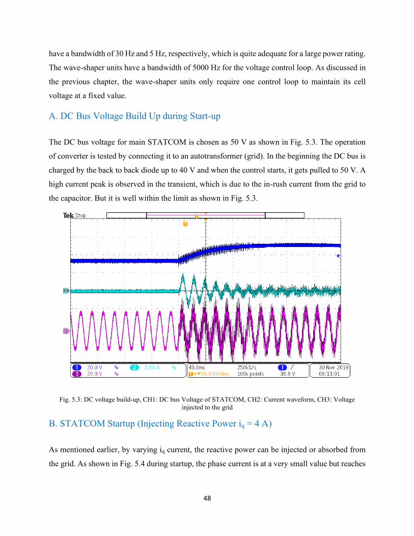
A. DC Bus Voltage Build Up during Start-up
The DC bus voltage for main STATCOM is chosen as 50 V as shown in Fig. 5.3. The operation
of converter is tested by connecting it to an autotransformer (grid). In the beginning the DC bus is
charged by the back to back diode up to 40 V and when the control starts, it gets pulled to 50 V. A
high current peak is observed in the transient, which is due to the in-rush current from the grid to
the capacitor. But it is well within the limit as shown in Fig. 5.3.
Fig. 5.3: DC voltage build-up, CH1: DC bus Voltage of STATCOM, CH2: Current waveform, CH3: Voltage
injected to the grid
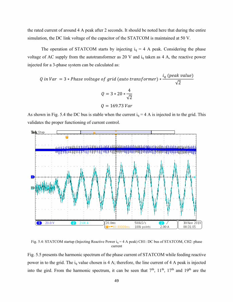
B. STATCOM Startup (Injecting Reactive Power iq = 4 A)
As mentioned earlier, by varying iq current, the reactive power can be injected or absorbed from
the grid. As shown in Fig. 5.4 during startup, the phase current is at a very small value but reaches
49
the rated current of around 4 A peak after 2 seconds. It should be noted here that during the entire
simulation, the DC link voltage of the capacitor of the STATCOM is maintained at 50 V.
The operation of STATCOM starts by injecting iq = 4 A peak. Considering the phase
voltage of AC supply from the autotransformer as 20 V and iq taken as 4 A, the reactive power
injected for a 3-phase system can be calculated as:
𝑄 𝑖𝑛 𝑉𝑎𝑟 = 3 ∗ 𝑃ℎ𝑎𝑠𝑒 𝑣𝑜𝑙𝑡𝑎𝑔𝑒 𝑜𝑓 𝑔𝑟𝑖𝑑 (𝑎𝑢𝑡𝑜 𝑡𝑟𝑎𝑛𝑠𝑓𝑜𝑟𝑚𝑒𝑟) ∗𝑖𝑞 (𝑝𝑒𝑎𝑘 𝑣𝑎𝑙𝑢𝑒)
√2
𝑄 = 3 ∗ 20 ∗4
√2
𝑄 = 169.73 𝑉𝑎𝑟
As shown in Fig. 5.4 the DC bus is stable when the current iq = 4 A is injected in to the grid. This
validates the proper functioning of current control.
Fig. 5.4: STATCOM startup (Injecting Reactive Power iq = 4 A peak) CH1: DC bus of STATCOM, CH2: phase
current
Fig. 5.5 presents the harmonic spectrum of the phase current of STATCOM while feeding reactive
power in to the grid. The iq value chosen is 4 A; therefore, the line current of 4 A peak is injected
into the gird. From the harmonic spectrum, it can be seen that 7th, 11th, 17th and 19th are the
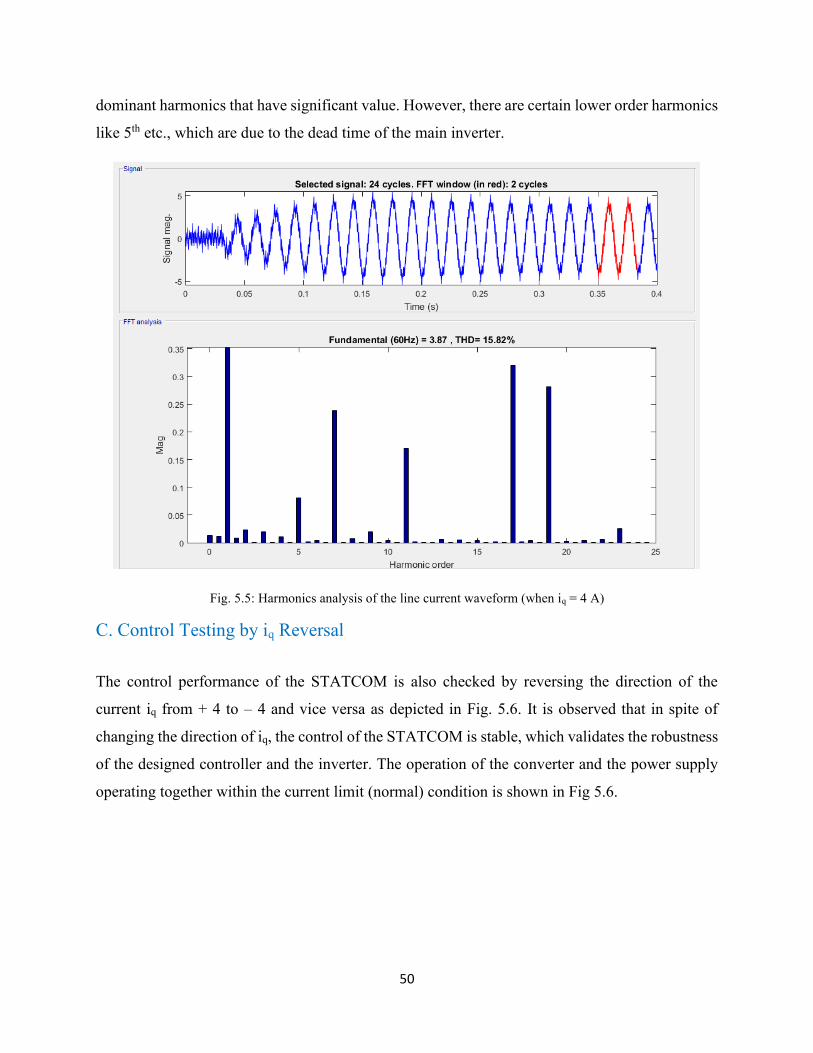
50
dominant harmonics that have significant value. However, there are certain lower order harmonics
like 5th etc., which are due to the dead time of the main inverter.
Fig. 5.5: Harmonics analysis of the line current waveform (when iq = 4 A)
C. Control Testing by iq Reversal
The control performance of the STATCOM is also checked by reversing the direction of the
current iq from + 4 to – 4 and vice versa as depicted in Fig. 5.6. It is observed that in spite of
changing the direction of iq, the control of the STATCOM is stable, which validates the robustness
of the designed controller and the inverter. The operation of the converter and the power supply
operating together within the current limit (normal) condition is shown in Fig 5.6.

51
Fig. 5.6: For iq Reversal (Reactive power flow control); mention the details of the waveforms
Hence forth, the controller response is instantaneous as the change in load current is responded by
the STATCOM.
D. STATCOM Output Waveform
Fig. 5.7 and Fig. 5.8 represent the STATCOM phase current prior to the wave-shaper function and
its harmonic spectrum, respectively. It should be noted from the harmonic spectrum that the
presence of the 5th ,7th and 11th harmonics are the one which are closest to the fundamental,
resulting in poor current waveform quality.
Fig. 5.9 and Fig. 5.10 presents the STATCOM phase-current after the wave-shaper units
start functioning followed by its harmonic spectrum respectively. It should be observed from the
harmonic spectrum that the 5th ,7th and 11th harmonics which are closest to the fundamental are
mitigated after the wave-shaper units become functional, improving the current waveform quality.

52
Fig. 5.7: Current wave-shape before wave-shaper starts functioning, CH1: Pole voltage wrt DC bus negative
terminal, CH2: Line current, CH3: H-bridge injected voltage
Fig. 5.8: Harmonic spectrum of the hybrid STATCOM phase current before the wave-shaper functioning

53
Fig. 5.9: Current wave-shape after the wave-shaper functioning, CH1: Pole voltage wrt DC bus negative terminal,
CH2: Line current, CH3: H-bridge injected voltage
Fig. 5.10: Harmonic spectrum of the hybrid STATCOM phase current after the wave-shaper functioning

54
Table 5.2: Comparison of line current with and without harmonic cancellation
Without Harmonic Cancellation (Base Case) With Harmonic Cancellation
Line Current Waveform
Harmonic spectrum of the hybrid STATCOM phase current
before the wave-shaper functioning
Line Current Waveform
Harmonic spectrum of the hybrid STATCOM phase
current after the wave-shaper functioning
Reduction in Targeted Harmonics:
Harmonic components:
5th = 0.1 A (Due to dead time)
7th = 0.4 A (for mf = 9; (mf – 2))
11th = 0.25 A (for mf = 9; (mf + 2))
Harmonic components:
5th = 0.05 A (50 % reduction)
7th = 0.16 A (60 % reduction)
11th = 0.14 A (44 % reduction)
Total Harmonic Distortion:
THD = 21.14%
THD = 18.38%
The phase-current waveform has the 5th, 7th and 11th harmonic before the wave-shaper units starts
functioning. Once the wave-shaper units start, it takes a few cycles for the wave-shaper units to
stabilize after which these harmonics 5th, 7th and 11th are reduced, thus improving the overall
current waveform quality.
It should be observed from Table 5.2 that the lower order harmonics (5th, 7th and 11th) are
reduced. Also, there is a significant reduction in the targeted harmonics 5th, 7th and 11th and total

55
harmonic distortion is improved by 13.05 % with respect to the base case. The presence of DC
component in the harmonic spectrum of the both cases i.e. with or without wave-shaper unit
functional should be noted. This DC component is due to error in sensors and OPAL-RT. Since,
the proposed wave-shaper units can cancel out harmonics. The proof-of-concept is verified, and
similarly, other harmonics can be targeted and programmed for reduction in their values or
complete elimination. Furthermore, the results can be improved when testing the hybrid
STATCOM at higher voltages levels.
5.2 Concluding Remarks
The proposed hybrid STATCOM for the grid connection is implemented to evaluate and
demonstrate its performance on the scale-down prototype and is reported in this chapter. The pole
voltage is used to extract harmonics, which is then injected by the two-level STATCOM. Based
on the proposed harmonic cancellation method, the specific harmonics are extracted and only the
targeted harmonics are reduced to improve the power quality for the entire system. The results can
be further improved by testing at higher voltage and scale-up prototype. Therefore, the
performance of the hybrid STATCOM is verified through the simulations and experimental results.
The next chapter, concludes the thesis and presents the guidelines for future work.

56
6. Conclusions and Future Scope
6.1 Contribution and Conclusions
This thesis proposes and validates an idea of harmonic reduction in conventional STATCOM using
additional wave-shaper circuits. The proposed hybrid STATCOM (Conventional STATCOM with
wave-shaper units) is developed and demonstrated to have lower THD compared to the
conventional STATCOM. The following are the foremost conclusions of this thesis;
The two-level converter in the conventional STATCOM is switched at a higher frequency as
compared to the Hybrid STATCOM. Further, the conventional STATCOM might require
additional filters to limit the current THD within bounds.
The Hybrid STATCOM has lower losses as compared to the conventional STATCOM. Though
it has a higher number of switches, the savings in losses might offset the additional cost of the
switches within a few years.
The control for the Hybrid STATCOM was developed, which could inject the required amount
of reactive power from its two-level converter and cancel the required harmonics from the
wave-shaper cells.
The Hybrid STATCOM could pose some challenges, especially since the wave-shapers are
connected in series. For example, an open circuit fault of the wave-shapers can disrupt the
complete reactive power flow. But this can be addressed by bypassing the faulty wave-shaper
cells.
6.2 Future Scope
This thesis presented a preliminary analysis of a Hybrid STATCOM for reactive power
compensation. This Hybrid STATCOM had lower THD as compared to the conventional
STATCOM. More work is required in this area to strengthen the concept and is listed below;
Currently an SPWM is used at a constant switching frequency for the two-level converter of
the Hybrid STATCOM. Other PWM schemes, such as selective-harmonic-elimination,
optimum PWM, etc., can be explored.

57
Further, based on this, the number of wave-shapers and their switching frequencies can be
optimized ensuring the lowest losses for the complete system.
The wave-shapers can do series Var injection apart from the harmonic cancellation. This will
require a system-level control and can be investigated in the future.

58
References
[1] Prasad, JS Siva, et al. "Vector control of three-phase AC/DC front-end
converter." Sadhana 33.5(2008): 591-613.
[2] B. Singh, R. Saha, A. Chandra, K. Al-Haddad. “Static synchronous compensators
(STATCOM): a review.” IEEE Transactions on Power Electronics 28.1 (2008)
[3] Poddar, Gautam, and Malaya Kumar Sahu. "Natural harmonic elimination of square-wave
inverter for medium-voltage application." IEEE Transactions on Power Electronics 24.5
(2009): 1182-1188
[4] Sahu, Malaya Kumar, and Gautam Poddar. "Transformer-less hybrid topology for
medium-voltage reactive-power compensation." IEEE Transactions on Power
Electronics 26.5 (2011): 1469-1479
[5] Blaabjerg F et al. Power losses in PWM-VSI inverter using NPT or PT IGBT devices.
IEEE Trans Power Electron 1995; 10:358–67
[6] Yazdani A, Iravani R. Voltage-sourced converters in power systems: modeling control, and
applications. Hoboken (New Jersey): John Wiley & Sons, Inc.; 2010
[7] Giddani Kalcon, Grain P. Adam, Olimpo Anaya-Lara, Graeme Burt, K.L. Lo, “Analytical
efficiency evaluation of two and three-level VSC-HVDC transmission links” Electrical
Power and Energy Systems, Vol. 4, pp. 1-6, 2013
[8] N. G. Hingoranl, L. Gyugyi, and M. E. El-Hawary, Understanding FACTS: Concepts and
technology of flexible ac transmission systems. 1999.
[9] J. Arrillaga, Y. H. Liu, and N. R. Watson, Flexible Power Transmission: The HVDC
Options. 2007.
[10] P. Wang, L. Goel, X. Liu, and F. H. Choo, “Harmonizing AC and DC: A Hybrid AC/DC
future grid solution,” IEEE Power Energy Mag., 2013.
[11] B. Singh, V. Mukherjee, and P. Tiwari, “A survey on impact assessment of DG and FACTS
controllers in power systems,” Renewable and Sustainable Energy Reviews. 2015.
[12] N. Flourentzou, V. G. Agelidis, and G. D. Demetriades, “VSC-based HVDC power
transmission systems: An overview,” IEEE Transactions on Power Electronics. 2009.
[13] L. Zhang, L. Harnefors, and H. P. Nee, “Interconnection of two very weak AC systems by
VSC-HVDC links using power-synchronization control,” IEEE Trans. Power Syst., 2011.

59
[14] F. M. Albatsh, S. Mekhilef, S. Ahmad, H. Mokhlis, and M. A. Hassan, “Enhancing power
transfer capability through flexible AC transmission system devices: a review,” Frontiers
of Information Technology and Electronic Engineering. 2015.
[15] R. S. Thallam, M. E. El-Hawary, C. A. Gross, A. G. Phadke, R. B. Gungor, and J. D.
Glover, “Transmissions,” in Systems, Controls, Embedded Systems, Energy, and
Machines, 2017.
[16] S. Do Nascimento and M. M. Gouvêa, “Voltage Stability Enhancement in Power Systems
with Automatic Facts Device Allocation,” in Energy Procedia, 2017.
[17] S. Abe, Y. Fukunaga, A. Isono, and B. Kondo, “Power system voltage stability,” IEEE
Trans. Power Appar. Syst., 1982.
[18] S. Corsi, “Voltage stability,” in Advances in Industrial Control, 2015.
[19] S. Chakrabarti, “Notes on power system voltage stability,” Dept. EE, IIT, Kanpur, 2011.
[20] T. Zabaiou, L. A. Dessaint, and I. Kamwa, “Preventive control approach for voltage
stability improvement using voltage stability constrained optimal power flow based on
static line voltage stability indices,” IET Gener. Transm. Distrib., 2014.
[21] G. K. Morison, B. Gao, and P. Kundur, “Voltage stability analysis using static and dynamic
approaches,” IEEE Trans. Power Syst., 1993.
[22] J. W. Simpson-Porco, F. Dörfler, and F. Bullo, “Voltage collapse in complex power grids,”
Nat. Commun., 2016.
[23] B. Singh, R. Saha, A. Chandra, and K. Al-Haddad, “Static synchronous compensators
(STATCOM): A review,” IET Power Electron., 2009.
[24] R. K. Varma, S. A. Rahman, and T. Vanderheide, “New Control of PV Solar Farm as
STATCOM (PV-STATCOM) for Increasing Grid Power Transmission Limits During
Night and Day,” IEEE Trans. Power Deliv., 2015.
[25] R. K. Varma and E. M. Siavashi, “PV-STATCOM: A New Smart Inverter for Voltage
Control in Distribution Systems,” IEEE Trans. Sustain. Energy, 2018.
[26] T. L. Lee, S. H. Hu, and Y. H. Chan, “D-STATCOM with positive-sequence admittance
and negative-sequence conductance to mitigate voltage fluctuations in high-level
fenetration of distributed-generation systems,” IEEE Trans. Ind. Electron., 2013.
60
[27] O. K. Shinde and V. R. S. V. B. Pulavarthi, “STATCOM converters and control: A
review,” in 2017 International Conference on Data Management, Analytics and
Innovation, ICDMAI 2017, 2017.
[28] M. Prasad and A. K. Akella, “Mitigation of power quality problems using custom power
devices: A review,” Indonesian Journal of Electrical Engineering and Informatics. 2017.
[29] M. Ebeed, S. Kamel, and H. Youssef, “Optimal setting of STATCOM based on voltage
stability improvement and power loss minimization using Moth-Flame algorithm,” in 2016
18th International Middle-East Power Systems Conference, MEPCON 2016 - Proceedings,
2017.
[30] L. Wang, C. H. Chang, B. L. Kuan, and A. V. Prokhorov, “Stability Improvement of a
Two-Area Power System Connected with an Integrated Onshore and Offshore Wind Farm
Using a STATCOM,” IEEE Trans. Ind. Appl., 2017.
[31] E. Hossain, M. R. Tur, S. Padmanaban, S. Ay, and I. Khan, “Analysis and Mitigation of
Power Quality Issues in Distributed Generation Systems Using Custom Power Devices,”
IEEE Access, 2018.
[32] P. M. Chavan and G. P. Chavan, “Interfacing of hybrid power system to grid using statcom
& power quality improvement,” in IEEE International Conference on Information,
Communication, Instrumentation and Control, ICICIC 2017, 2018.
[33] M. R. Nasiri, S. Farhangi, and J. Rodriguez, “Model Predictive Control of a Multilevel
CHB STATCOM in Wind Farm Application Using Diophantine Equations,” IEEE Trans.
Ind. Electron., 2019.
[34] T. Tanaka, K. Ma, H. Wang, and F. Blaabjerg, “Asymmetrical Reactive Power Capability
of Modular Multilevel Cascade Converter Based STATCOMs for Offshore Wind Farm,”
IEEE Trans. Power Electron., 2019.
[35] M. Narimani, B. Wu, and N. R. Zargari, “A novel five-level voltage source inverter with
sinusoidal pulse width modulator for medium-voltage applications,” IEEE Trans. Power
Electron., 2016.
[36] J. Shri harsha, G. N. Shilpa, E. Ramesh, L. . Dayananda, and C. Nataraja, “Voltage Source
Converter Based HVDC Transmission,” International Journal of Engineering Science and
Innovative Technology, 2012.

61
[37] B. Jacobson, P. Karlsson, G. Asplund, L. Harnefors, and T. Jonsson, “VSC-HVDC
transmission with cascaded two-level converters,” in 43rd International Conference on
Large High Voltage Electric Systems 2010, CIGRE 2010, 2010.
[38] R. Beres, X. Wang, F. Blaabjerg, C. L. Bak, and M. Liserre, “A review of passive filters
for grid-connected voltage source converters,” in Conference Proceedings - IEEE Applied
Power Electronics Conference and Exposition - APEC, 2014.
[39] Mohan, Ned, and Tore M. Undeland. Power electronics: converters, applications, and
design. John Wiley & Sons, 2007.
[40] K. S. Amitkumar, G. B. Mahmud, P. Tamanwe, S. Navjot, A. K. Rathore and P. Pillay, "A
hybrid switching VSC based converter for reactive power compensation in utility grid,"
2017 IEEE International Conference on Environment and Electrical Engineering and 2017
IEEE Industrial and Commercial Power Systems Europe (EEEIC / I&CPS Europe), Milan,
2017, pp. 1-4, doi: 10.1109/EEEIC.2017.7977709.
[41] http://www.opal-rt.com/simulator-platform-op4510/
[42] http://www.opal-rt.com/systems-efpgasim/


![STATCOM BASED ON MODULAR MULTILEVEL CONVERTER: …strathprints.strath.ac.uk/40646/7/Adam_etal_IET... · source modular multilevel converter is adopted to FACTS devices[1, 5, 8-11]](https://img.pdfslide.us/doc/110x75/5f05593f7e708231d41285c5/statcom-based-on-modular-multilevel-converter-source-modular-multilevel-converter.jpg)