Embed Size (px)
Citation preview

XCP
Version 1.0
“The Universal Measurement and Calibration Protocol Family”
Part 1 Overview
Association for Standardization of Automation and Measuring Systems
Dated:2003-04-08
© ASAM e.V.
XCP -Part 1- Overview -1.0.doc 2
Status of Document
Date: 2003-04-08 Authors: Roel Schuermans, Vector Informatik GmbH
Rainer Zaiser, Vector Informatik GmbH Frank Hepperle, DaimlerChrysler AG Hans Schröter, DaimlerChrysler AG Reiner Motz, Robert Bosch GmbH Andreas Aberfeld, Robert Bosch GmbH Hans-Georg Kunz, Siemens VDO Automotive AG Thomas Tyl, Siemens VDO Automotive AG Robert Leinfellner, dSPACE GmbH Hendirk Amsbeck, dSPACE GmbH Harald Styrsky, Compact Dynamics GmbH Boris Ruoff, ETAS GmbH Lars Wahlmann, Accurate Technologies Inc.
Version: 1.0 Doc-ID: XCP -Part 1- Overview -1.0 Status: Released Type Final
Disclaimer of Warranty Although this document was created with the utmost care it cannot be guaranteed that it is completely free of errors or inconsistencies. ASAM e.V. makes no representations or warranties with respect to the contents or use of this documentation, and specifically disclaims any expressed or implied warranties of merchantability or fitness for any particular purpose. Neither ASAM nor the author(s) therefore accept any liability for damages or other consequences that arise from the use of this document. ASAM e.V. reserves the right to revise this publication and to make changes to its content, at any time, without obligation to notify any person or entity of such revisions or changes.

XCP -Part 1- Overview -1.0.doc 3
Revision History
This revision history shows only major modifications between release versions. Date Author Filename Comments 2003-04-08 R.Schuermans Released document

XCP -Part 1- Overview -1.0.doc 4
Table of contents
0 Introduction ........................................................................................................7 0.1 The XCP Protocol Family............................................................................................... 7
0.2 Documentation Overview............................................................................................... 8
0.3 Definitions and Abbreviations........................................................................................ 9
1 XCP Features....................................................................................................10 1.1 Synchronous Data Transfer .......................................................................................... 11 1.1.1 The Synchronous Data Transfer Model (basic)....................................................... 11
1.1.1.1 General: DAQ, STIM and ODT .......................................................................... 11 1.1.1.2 ODT entry ........................................................................................................ 12 1.1.1.3 Object Description Table (ODT)......................................................................... 13 1.1.1.4 DAQ list ........................................................................................................... 14 1.1.1.5 Event channels................................................................................................. 15
1.1.2 The Synchronous Data Transfer Model (optional features) .................................... 16 1.1.2.1 Dynamic DAQ Configuration.............................................................................. 16 1.1.2.2 Advanced features............................................................................................ 18
1.1.2.2.1 power-up data transfer (RESUME mode) ......................................................... 18 1.1.2.2.2 Master-slave synchronization ......................................................................... 20 1.1.2.2.3 DAQ list prioritization.................................................................................. 21 1.1.2.2.4 ODT optimization........................................................................................ 22 1.1.2.2.5 Bitwise stimulation ...................................................................................... 24
1.1.3 The Synchronous Data Transfer DIRECTION........................................................ 25 1.1.3.1 Synchronous data acquisition (DAQ) ................................................................. 25 1.1.3.2 Synchronous data stimulation (STIM)................................................................. 26 1.1.3.3 Bypassing (BYP) .............................................................................................. 27
1.2 Online Calibration ........................................................................................................ 28 1.2.1 The Online Data Calibration Model (basic) ............................................................ 28
1.2.1.1 General: SECTOR, SEGMENT and PAGE......................................................... 28 1.2.1.2 Logical lay-out: SEGMENT................................................................................ 29 1.2.1.3 Accessability: PAGE ......................................................................................... 30
1.2.2 The Online Data Calibration Model (optional features).......................................... 31 1.2.2.1 Calibration Data Page Switching........................................................................ 31 1.2.2.2 Advanced features............................................................................................ 32
1.2.2.2.1 Calibration Data Page Freezing ...................................................................... 32 1.2.3 The Online Data Calibration actions ....................................................................... 33
1.2.3.1 Addressing....................................................................................................... 33 1.2.3.2 Master - slave .................................................................................................. 34 1.2.3.3 Page – page..................................................................................................... 35
1.3 Flash programming....................................................................................................... 36 1.3.1 The Flashing Model ................................................................................................. 36
1.3.1.1 Physical lay-out: SECTOR ................................................................................ 36 1.3.1.2 General:........................................................................................................... 37 1.3.1.3 Absolute Access Mode : access by address ....................................................... 38 1.3.1.4 Functional Access Mode : access by flash area .................................................. 39

XCP -Part 1- Overview -1.0.doc 5
1.3.1.5 Checksum Control and Program Verify .............................................................. 41 1.3.1.6 End of Flash Session ........................................................................................ 42
2 The XCP Protocol.............................................................................................43 2.1 Topology....................................................................................................................... 43
2.2 The XCP communication models ................................................................................. 45 2.2.1 The Standard communication model ....................................................................... 45 2.2.2 The Block Transfer communication model ............................................................. 46 2.2.3 The Interleaved communication model ................................................................... 47
2.3 State machine................................................................................................................ 48
2.4 The XCP Message (Frame) Format .............................................................................. 51
3 The Limits of Performance..............................................................................52 3.1 Generic performance parameters.................................................................................. 52
3.2 DAQ/STIM specific performance parameters.............................................................. 53 3.2.1 DAQ specific parameters......................................................................................... 54 3.2.2 STIM specific parameters........................................................................................ 54
4 Versioning ........................................................................................................55 4.1 The XCP Protocol Layer Version Number................................................................... 55
4.2 The XCP Transport Layer Version Number................................................................. 56
4.3 The Compatibility Matrix............................................................................................. 57
XCP -Part 1- Overview -1.0.doc 6
Table of diagrams: Diagram 1 : ODT List Organization..................................................................................... 11 Diagram 2 : DAQ List Organization .................................................................................... 14 Diagram 3 : RESUME mode ................................................................................................ 18 Diagram 4 : Calibration Data Organisation........................................................................ 28 Diagram 5 : address calculation .......................................................................................... 33 Diagram 6 : Absolute Access Mode ................................................................................... 38 Diagram 7 : Functional Access Mode................................................................................. 39 Diagram 8 : The XCP Topology .......................................................................................... 43 Diagram 9 : Standard Communication Model ................................................................... 45 Diagram 10 : Master Block Transfer................................................................................... 46 Diagram 11 : Slave Block Transfer ..................................................................................... 46 Diagram 12 : Interleaved Communication Model ............................................................. 47 Diagram 13 : The XCP slave State Machine..................................................................... 48 Diagram 14 : Typical use of CONNECT modes USER_DEFINED and NORMAL ..... 49 Diagram 15 : The XCP Message (Frame) format............................................................. 51
XCP -Part 1- Overview -1.0.doc 7
0 Introduction
0.1 The XCP Protocol Family
This document is based on experiences with the CAN Calibration Protocol (CCP) version 2.1 as described in feedback from the companies Accurate Technologies Inc., Compact Dynamics GmbH, DaimlerChrysler AG, dSPACE GmbH, ETAS GmbH, Kleinknecht Automotive GmbH, Robert Bosch GmbH, Siemens VDO Automotive AG and Vector Informatik GmbH.
The XCP Specification documents describe an improved and generalized version of CCP.
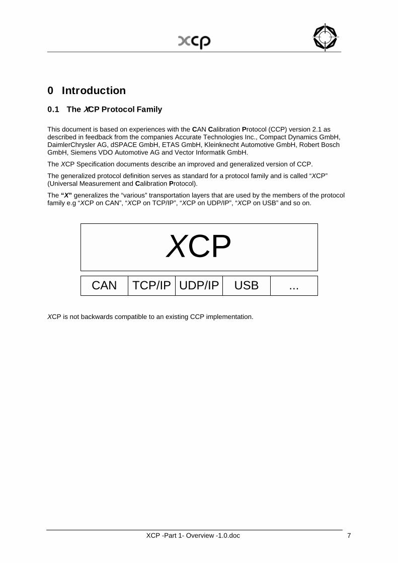
The generalized protocol definition serves as standard for a protocol family and is called “XCP” (Universal Measurement and Calibration Protocol).
The “X” generalizes the “various” transportation layers that are used by the members of the protocol family e.g “XCP on CAN”, “XCP on TCP/IP”, “XCP on UDP/IP”, “XCP on USB” and so on.
XCPCAN TCP/IP UDP/IP USB ...
XCP is not backwards compatible to an existing CCP implementation.
XCP -Part 1- Overview -1.0.doc 8
0.2 Documentation Overview
The XCP specification consists of 5 parts. Each part is a separate document and has the following contents: Part 1 “Overview” gives an overview over the XCP protocol family, the XCP features and the fundamental protocol definitions (this document). Part 2 “Protocol Layer Specification” defines the generic protocol, which is independent from the transportation layer used. Part 3 “Transport Layer Specification” defines the way how the XCP protocol is transported by a particular transportation layer like CAN, TCP/IP and UDP/IP. Part 4 “Interface Specification” defines the interfaces from an XCP master to an ASAM MCD 2MC description file and for calculating Seed & Key algorithms and checksums. Part 5 “Example Communication Sequences” gives example sequences for typical actions performed with XCP. Everything not explicitly mentioned in this document, should be considered as implementation specific.
XCP -Part 1- Overview -1.0.doc 9
0.3 Definitions and Abbreviations
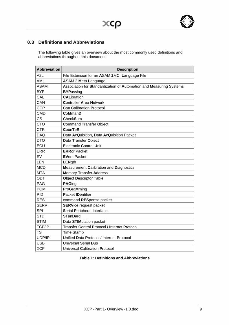
The following table gives an overview about the most commonly used definitions and abbreviations throughout this document.
Abbreviation Description A2L File Extension for an ASAM 2MC Language File AML ASAM 2 Meta Language ASAM Association for Standardization of Automation and Measuring Systems BYP BYPassing CAL CALibration CAN Controller Area Network CCP Can Calibration Protocol CMD CoMmanD CS CheckSum CTO Command Transfer Object CTR CounTeR DAQ Data AcQuisition, Data AcQuisition Packet DTO Data Transfer Object ECU Electronic Control Unit ERR ERRor Packet EV EVent Packet LEN LENgth MCD Measurement Calibration and Diagnostics MTA Memory Transfer Address ODT Object Descriptor Table PAG PAGing PGM ProGraMming PID Packet IDentifier RES command RESponse packet SERV SERVice request packet SPI Serial Peripheral Interface STD STanDard STIM Data STIMulation packet TCP/IP Transfer Control Protocol / Internet Protocol TS Time Stamp UDP/IP Unified Data Protocol / Internet Protocol USB Universal Serial Bus XCP Universal Calibration Protocol
Table 1: Definitions and Abbreviations
XCP -Part 1- Overview -1.0.doc 10
1 XCP Features XCP provides the following basic features:
- Synchronous data acquisition - Synchronous data stimulation - Online memory calibration (read / write access) - Calibration data page initialization and switching - Flash Programming for ECU development purposes
XCP provides the following optional, new features:
- Various transportation layers (CAN, Ethernet, USB,…) - Block communication mode - Interleaved communication mode - Dynamic data transfer configuration - Timestamped data transfer - Synchronization of data transfer - Priotization of data transfer - Atomic bit modification - Bitwise data stimulation
XCP improves the following features compared to CCP 2.1:
- compatibility and specification - efficiency and throughput - power-up data transfer - data page freezing - auto configuration - flash programming.
XCP was designed according to the following principles:
- Minimal Slave resource consumption (RAM, ROM, runtime) - Efficient communication - Simple Slave implementation
XCP -Part 1- Overview -1.0.doc 11
1.1 Synchronous Data Transfer
1.1.1 The Synchronous Data Transfer Model (basic)
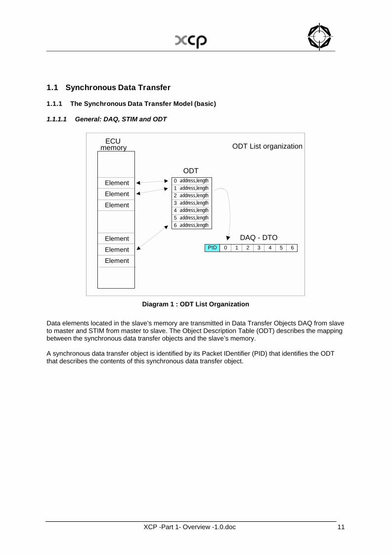
1.1.1.1 General: DAQ, STIM and ODT
Element Element
Element Element Element
Element
ECU memory
0 1 2 3 4 5 6
address,length address,length address,length address,length address,length address,length address,length
PID 5 6 3 4 2 1 0
ODT
DAQ - DTO
ODT List organization
Diagram 1 : ODT List Organization
Data elements located in the slave’s memory are transmitted in Data Transfer Objects DAQ from slave to master and STIM from master to slave. The Object Description Table (ODT) describes the mapping between the synchronous data transfer objects and the slave’s memory. A synchronous data transfer object is identified by its Packet IDentifier (PID) that identifies the ODT that describes the contents of this synchronous data transfer object.
XCP -Part 1- Overview -1.0.doc 12
1.1.1.2 ODT entry An entry in an ODT references a data element by its address, the address extension, the size of the element in ADDRESS_GRANULARITY and for a data element that represents a bit, the bit offset. For the address of the element described by an ODT entry, the following has to be fulfilled :
Address mod GRANULARITY_ODT_ENTRY_SIZE_x = 0 For every size of the element described by an ODT entry, the following has to be fulfilled :
SizeOf(element described by ODT entry) mod GRANULARITY_ODT_ENTRY_SIZE_x = 0 The possible values for GRANULARITY_ODT_ENTRY_SIZE_x are {1,2,4,8}. The possible values for ADDRESS_GRANULARITY are {1,2,4}. The following relation must be fulfilled :
GRANULARITY_ODT_ENTRY_SIZE_x mod ADDRESS_GRANULARITY = 0 The MAX_ODT_ENTRY_SIZE_x parameters indicate the upper limits for the size of the element described by an ODT entry in ADDRESS_GRANULARITY. For every size of the element described by an ODT entry the following has to be fulfilled :
SizeOf(element described by ODT entry) <= MAX_ODT_ENTRY_SIZE_x If a slave only supports elements with size = BYTE, the master has to split up multi-byte data elements into single bytes. An ODT entry is referenced by an ODT_ENTRY_NUMBER.
XCP -Part 1- Overview -1.0.doc 13
1.1.1.3 Object Description Table (ODT) ODT entries are grouped in ODTs. If DAQ lists are configured statically, MAX_ODT_ENTRIES specifies the maximum number of ODT entries in each ODT of this DAQ list. If DAQ lists are configured dynamically, MAX_ODT_ENTRIES is not fixed and will be 0. For every ODT the numbering of the ODT entries through ODT_ENTRY_NUMBER restarts from 0
ODT_ENTRY_NUMBER [0,1,..MAX_ODT_ENTRIES(DAQ list)-1] An ODT is referenced by an ODT_NUMBER.
XCP -Part 1- Overview -1.0.doc 14
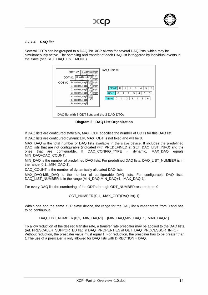
1.1.1.4 DAQ list Several ODTs can be grouped to a DAQ-list. XCP allows for several DAQ-lists, which may be simultaneously active. The sampling and transfer of each DAQ-list is triggered by individual events in the slave (see SET_DAQ_LIST_MODE).
0123456
address,lengthaddress,lengthaddress,lengthaddress,lengthaddress,lengthaddress,lengthaddress,length
0123456
address,lengthaddress,lengthaddress,lengthaddress,lengthaddress,lengthaddress,lengthaddress,length
0123456
address,lengthaddress,lengthaddress,lengthaddress,lengthaddress,lengthaddress,lengthaddress,length
ODT #0
ODT #1
ODT #2DAQ List #0
DAQ list with 3 ODT lists and the 3 DAQ-DTOs
PID=0 5 63 4210
PID=1 5 63 4210
PID=2 5 63 4210
Diagram 2 : DAQ List Organization
If DAQ lists are configured statically, MAX_ODT specifies the number of ODTs for this DAQ list. If DAQ lists are configured dynamically, MAX_ODT is not fixed and will be 0. MAX_DAQ is the total number of DAQ lists available in the slave device. It includes the predefined DAQ lists that are not configurable (indicated with PREDEFINED at GET_DAQ_LIST_INFO) and the ones that are configurable. If DAQ_CONFIG_TYPE = dynamic, MAX_DAQ equals MIN_DAQ+DAQ_COUNT. MIN_DAQ is the number of predefined DAQ lists. For predefined DAQ lists, DAQ_LIST_NUMBER is in the range [0,1,..MIN_DAQ-1]. DAQ_COUNT is the number of dynamically allocated DAQ lists. MAX_DAQ-MIN_DAQ is the number of configurable DAQ lists. For configurable DAQ lists, DAQ_LIST_NUMBER is in the range [MIN_DAQ,MIN_DAQ+1,..MAX_DAQ-1]. For every DAQ list the numbering of the ODTs through ODT_NUMBER restarts from 0
ODT_NUMBER [0,1,..MAX_ODT(DAQ list)-1] Within one and the same XCP slave device, the range for the DAQ list number starts from 0 and has to be continuous.
DAQ_LIST_NUMBER [0,1,..MIN_DAQ-1] + [MIN_DAQ,MIN_DAQ+1,..MAX_DAQ-1] To allow reduction of the desired transfer rate, a transfer rate prescaler may be applied to the DAQ lists. (ref. PRESCALER_SUPPORTED flag in DAQ_PROPERTIES at GET_DAQ_PROCESSOR_INFO). Without reduction, the prescaler value must equal 1. For reduction, the prescaler has to be greater than 1.The use of a prescaler is only allowed for DAQ lists with DIRECTION = DAQ.
XCP -Part 1- Overview -1.0.doc 15
1.1.1.5 Event channels XCP allows for several DAQ-lists, which may be simultaneously active. The sampling and transfer of each DAQ-list is triggered by individual events in the slave (see SET_DAQ_LIST_MODE). An event channel builds the generic signal source that effectively determines the data transfer timing. MAX_EVENT_CHANNEL is the number of available event channels Within one and the same XCP slave device, the range for the event channel number starts from 0 and has to be continuous.
EVENT_CHANNEL_NUMBER [0,1,..MAX_EVENT_CHANNEL-1] For each event channel MAX_DAQ_LIST indicates the maximum number of DAQ lists that can be allocated to this event channel. MAX_DAQ_LIST = 0 means there’s no limitation. XCP allows for the prioritization of event channels. This prioritization is a fixed attribute of the slave and therefore read-only. The event channel with event channel priority = FF has the highest priority. The assignment of MEASUREMENT variables to event channels can optionally be controlled in the section DAQ_EVENT local at each definition of the MEASUREMENT variable. The assignment can either be fixed or variable. If the assignment shall be fixed, a list with all event channels to be used (FIXED_EVENT_LIST) must be defined at any MEASUREMENT variable where the fixed assignment is required. The tool cannot change the assignment of the event channels for a MEASUREMENT variable with a fixed list. If the assignment shall not be fixed but variable, a list with all valid events channels for this MEASUREMENT (AVAILABLE_EVENT_LIST) can be provided local at the MEASUREMENT. In case that such lists does not exist, all event channels provided by the ECU can be assigned by the tool. A default assignment of the event channels to the MEASUREMENT variables can be supported by providing a list with the default event channels (DEFAULT_EVENT_LIST). This default assignment can be changed by the tool to a different assignment. In case an AVAILABLE_EVENT LIST is defined, the event channels in the DEFAULT_EVENT_LIST must be the same or a sub-set of the event channels in the AVAILABLE_EVENT_LIST for this MEASUREMENT variable. Lists are possible as some MCD tools allow measurement in multiple events. Lists provide the user of a tool a simplified measurement configuration.
XCP -Part 1- Overview -1.0.doc 16
1.1.2 The Synchronous Data Transfer Model (optional features)
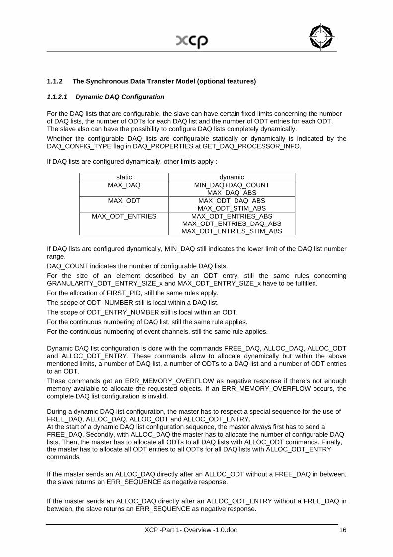
1.1.2.1 Dynamic DAQ Configuration For the DAQ lists that are configurable, the slave can have certain fixed limits concerning the number of DAQ lists, the number of ODTs for each DAQ list and the number of ODT entries for each ODT. The slave also can have the possibility to configure DAQ lists completely dynamically. Whether the configurable DAQ lists are configurable statically or dynamically is indicated by the DAQ_CONFIG_TYPE flag in DAQ_PROPERTIES at GET_DAQ_PROCESSOR_INFO. If DAQ lists are configured dynamically, other limits apply :
static dynamic MAX_DAQ MIN_DAQ+DAQ_COUNT
MAX_DAQ_ABS MAX_ODT MAX_ODT_DAQ_ABS
MAX_ODT_STIM_ABS MAX_ODT_ENTRIES MAX_ODT_ENTRIES_ABS
MAX_ODT_ENTRIES_DAQ_ABS MAX_ODT_ENTRIES_STIM_ABS
If DAQ lists are configured dynamically, MIN_DAQ still indicates the lower limit of the DAQ list number range. DAQ_COUNT indicates the number of configurable DAQ lists. For the size of an element described by an ODT entry, still the same rules concerning GRANULARITY_ODT_ENTRY_SIZE_x and MAX_ODT_ENTRY_SIZE_x have to be fulfilled. For the allocation of FIRST_PID, still the same rules apply. The scope of ODT_NUMBER still is local within a DAQ list. The scope of ODT_ENTRY_NUMBER still is local within an ODT. For the continuous numbering of DAQ list, still the same rule applies. For the continuous numbering of event channels, still the same rule applies. Dynamic DAQ list configuration is done with the commands FREE_DAQ, ALLOC_DAQ, ALLOC_ODT and ALLOC_ODT_ENTRY. These commands allow to allocate dynamically but within the above mentioned limits, a number of DAQ list, a number of ODTs to a DAQ list and a number of ODT entries to an ODT. These commands get an ERR_MEMORY_OVERFLOW as negative response if there’s not enough memory available to allocate the requested objects. If an ERR_MEMORY_OVERFLOW occurs, the complete DAQ list configuration is invalid. During a dynamic DAQ list configuration, the master has to respect a special sequence for the use of FREE_DAQ, ALLOC_DAQ, ALLOC_ODT and ALLOC_ODT_ENTRY. At the start of a dynamic DAQ list configuration sequence, the master always first has to send a FREE_DAQ. Secondly, with ALLOC_DAQ the master has to allocate the number of configurable DAQ lists. Then, the master has to allocate all ODTs to all DAQ lists with ALLOC_ODT commands. Finally, the master has to allocate all ODT entries to all ODTs for all DAQ lists with ALLOC_ODT_ENTRY commands. If the master sends an ALLOC_DAQ directly after an ALLOC_ODT without a FREE_DAQ in between, the slave returns an ERR_SEQUENCE as negative response. If the master sends an ALLOC_DAQ directly after an ALLOC_ODT_ENTRY without a FREE_DAQ in between, the slave returns an ERR_SEQUENCE as negative response.
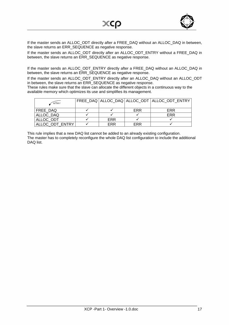
XCP -Part 1- Overview -1.0.doc 17
If the master sends an ALLOC_ODT directly after a FREE_DAQ without an ALLOC_DAQ in between, the slave returns an ERR_SEQUENCE as negative response. If the master sends an ALLOC_ODT directly after an ALLOC_ODT_ENTRY without a FREE_DAQ in between, the slave returns an ERR_SEQUENCE as negative response. If the master sends an ALLOC_ODT_ENTRY directly after a FREE_DAQ without an ALLOC_DAQ in between, the slave returns an ERR_SEQUENCE as negative response. If the master sends an ALLOC_ODT_ENTRY directly after an ALLOC_DAQ without an ALLOC_ODT in between, the slave returns an ERR_SEQUENCE as negative response. These rules make sure that the slave can allocate the different objects in a continuous way to the available memory which optimizes its use and simplifies its management.
a f te r
FREE_DAQ ALLOC_DAQ ALLOC_ODT ALLOC_ODT_ENTRY
FREE_DAQ ! ! ERR ERR ALLOC_DAQ ! ! ! ERR ALLOC_ODT ! ERR ! ! ALLOC_ODT_ENTRY ! ERR ERR !
This rule implies that a new DAQ list cannot be added to an already existing configuration. The master has to completely reconfigure the whole DAQ list configuration to include the additional DAQ list.
XCP -Part 1- Overview -1.0.doc 18
1.1.2.2 Advanced features
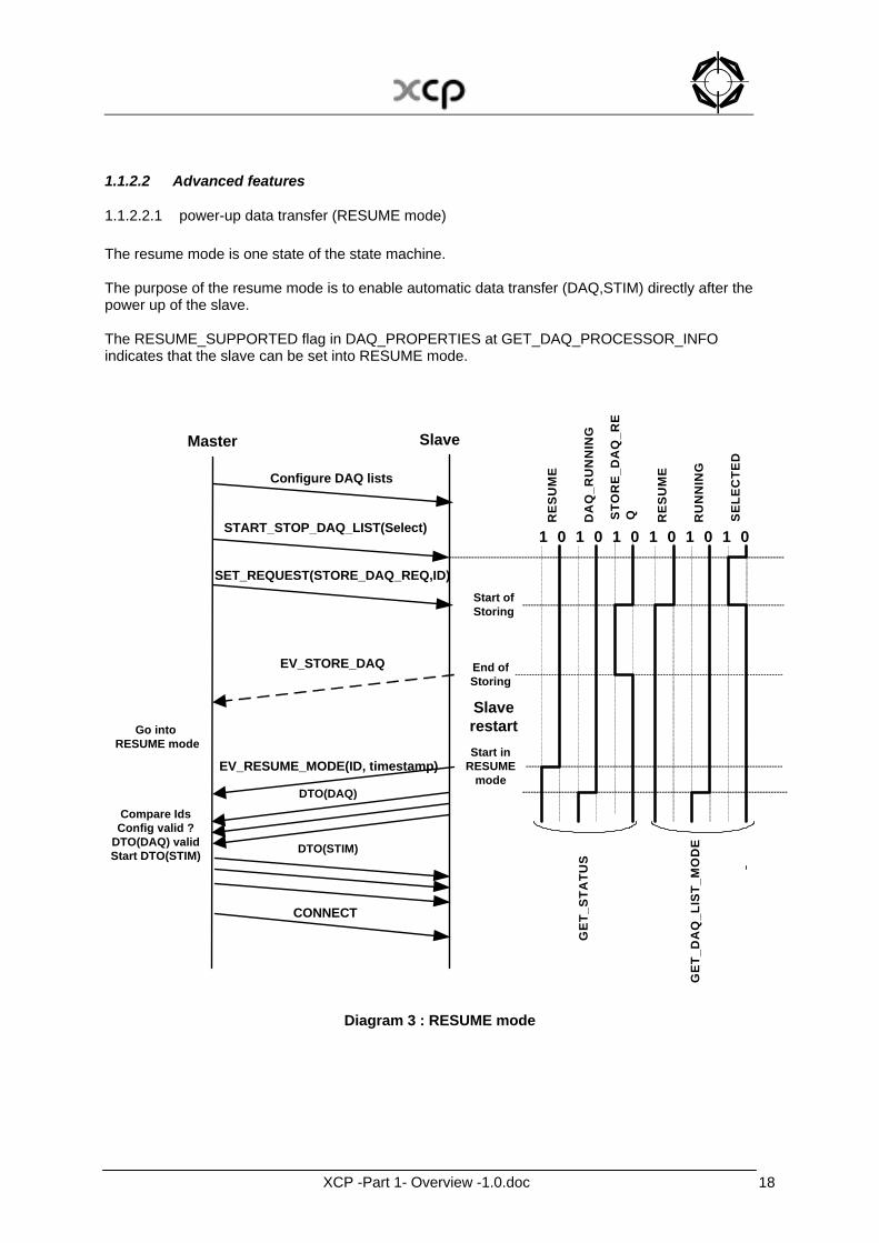
1.1.2.2.1 power-up data transfer (RESUME mode) The resume mode is one state of the state machine. The purpose of the resume mode is to enable automatic data transfer (DAQ,STIM) directly after the power up of the slave. The RESUME_SUPPORTED flag in DAQ_PROPERTIES at GET_DAQ_PROCESSOR_INFO indicates that the slave can be set into RESUME mode.
CONNECT
Start ofStoring
Start inRESUME
mode
Master Slave
Configure DAQ lists
START_STOP_DAQ_LIST(Select)
SET_REQUEST(STORE_DAQ_REQ,ID)
SlaverestartGo into
RESUME mode
EV_RESUME_MODE(ID, timestamp)
DTO(DAQ)
DTO(STIM)
Compare IdsConfig valid ?
DTO(DAQ) validStart DTO(STIM)
RE
SU
ME
0101 1 0 1 0 1 10 0
DA
Q_R
UN
NIN
G
STO
RE_
DA
Q_R
EQ RE
SU
ME
RU
NN
ING
SEL
ECTE
D
EV_STORE_DAQ End ofStoring
GET
_STA
TUS
GET
_DA
Q_L
IST_
MO
DE
Diagram 3 : RESUME mode
XCP -Part 1- Overview -1.0.doc 19
With GET_STATUS, the master can identify whether a slave is in RESUME mode. With START_STOP_DAQ_LIST(Select) , the master can select a DAQ list to be part of a DAQ list configuration the slave uses when being in RESUME mode. With GET_DAQ_LIST_MODE the master can identify whether a DAQ list is part of a DAQ list configuration the slave uses when in RESUME mode. The master has to calculate a Session Configuration Id based upon the current configuration of the DAQ lists selected for RESUME mode. The master has to store this Session Configuration Id internally for further use. The master also has to send the Session Configuration Id to the slave with SET_REQUEST. If STORE_DAQ_REQ is set, the slave internally has to set the RESUME bit of those DAQ lists that previously have been selected with START_STOP_DAQ_LIST(select). If STORE_DAQ_REQ is set and the appropriate conditions are met, the slave then has to save all DAQ lists which have the RESUME bit set, into non-volatile memory. If STORE_DAQ_REQ is set, the slave also has to store the Session Configuration Id in non-volatile memory. It will be returned in an EV_RESUME_MODE and in the response of GET_STATUS. This allows the master device to verify that automatically started DAQ lists contain the expected data transfer configuration. Upon saving, the slave first has to clear any DAQ list configuration that might already be stored in non-volatile memory. The STORE_DAQ_REQ bit obtained by GET_STATUS will be reset by the slave, when the request is fulfilled. The slave device may indicate this by transmitting an EV_STORE_DAQ event packet. RESUME mode is allowed for both directions, DAQ and STIM. On each power up, the slave has to restore the DAQ lists and send an EV_RESUME_MODE to the master.
Position Type Description 0 BYTE Packet ID: Event 0xFD 1 BYTE EV_RESUME_MODE: 0x00 2,3 WORD Session Configuration Id from slave 4..7 DWORD Current slave Timestamp (optional)
The EV_RESUME_MODE has to contain the Session Configuration Id. If the slave has the TIMESTAMP_SUPPORTED flag set in GET_DAQ_PROCESSOR_INFO, in Current slave Timestamp the EV_RESUME_MODE also has to contain the current value of the data acquisition clock. The Current slave Timestamp has the format specified by the GET_DAQ_RESOLUTION_INFO command. For DAQ list with DIRECTION = DAQ, then the slave automatically will start transferring DAQ packets to the master, even before any XCP command was sent by the master. For DAQ list with DIRECTION = STIM, then the slave automatically will be ready for receiving STIM packets from the master, even before any XCP command was sent by the master. For DAQ lists automatically started at power up, the Current Mode of GET_DAQ_LIST_MODE will be RESUME and RUNNING. The master and the slave have to remember all the necessary communication parameters that were used when a SET_REQUEST(STORE_DAQ_REQ) was sent. At power-up, both the master and the slave have to use these same parameters for the automatic data transfer.

XCP -Part 1- Overview -1.0.doc 20
1.1.2.2.2 Master-slave synchronization The GET_DAQ_CLOCK command provides a way to synchronize the clocks in the master and the slave device, by calculation of an offset.

XCP -Part 1- Overview -1.0.doc 21
1.1.2.2.3 DAQ list prioritization XCP allows the prioritization of DAQ-lists. The limited length of the DTOs together with the prioritization mechanism, makes sure that with an acceptable delay a DAQ list with higher priority can interrupt the transfer of a DAQ list with lower priority.
XCP -Part 1- Overview -1.0.doc 22
1.1.2.2.4 ODT optimization XCP allows DTO optimization on ODT level. To support this feature the slave implementation may use one or more specific copy routines in order to make full use of the CPUs architecture for copying data. Optimization can be done in a way to minimize runtime, or to maximize the effective data transfer rate, or even both. However these copy routines may need specific ODT structures. To get the advantage of DAQ optimization, the master should configure the ODTs in a way to fit the requirements of the copy routines. The Optimization_Method property indicates the kind of optimization method, used by the slave implementation. It should be used by the master to determine the method, used for configuring the ODTs. Optimization_Method is a global DAQ property, valid for all ODTs and DAQ lists. The Optimization_Method flags are located in DAQ_KEY_BYTE at GET_DAQ_PROCESSOR_INFO. The following Optimization Methods are defined:
OM_DEFAULT: No special requirements. GRANULARITY_ ODT _ENTRY_SIZE_DAQ, GRANULARITY_ODT _ENTRY_SIZE_STIM, MAX_ODT_ENTRY_SIZE_DAQ and MAX_ODT_ENTRY_SIZE_STIM must be considered.
OM_ODT_TYPE_16: Type specific copy routines are used on ODT level. WORD (16 Bit) is the largest type, supported by the copy routines. GRANULARITY_ ODT_ENTRY_SIZE_DAQ and GRANULARITY_ODT_ENTRY_SIZE_STIM define the smallest type. All entries within the same ODT should be of the same type. Length and address of each ODT entry must meet the alignment requirements of the ODT type. MAX_ODT_ENTRY_SIZE_DAQ and MAX_ODT_ENTRY_SIZE_STIM must be considered.
OM_ODT_TYPE_32: Type specific copy routines are used on ODT level. DWORD (32 Bit) is the largest type, supported by the copy routines. GRANULARITY_ ODT_ENTRY_SIZE_DAQ and GRANULARITY_ODT_ENTRY_SIZE_STIM define the smallest type. All entries within the same ODT should be of the same type. Length and address of each ODT entry must meet the alignment requirements of the ODT type. MAX_ODT_ENTRY_SIZE_DAQ and MAX_ODT_ENTRY_SIZE_STIM must be considered.
OM_ODT_TYPE_64: Type specific copy routines are used on ODT level. QWORD (64 Bit) is the largest type, supported by the copy routines. GRANULARITY_ ODT_ENTRY_SIZE_DAQ and GRANULARITY_ODT_ENTRY_SIZE_STIM define the smallest type. All entries within the same ODT should be of the same type. Length and address of each ODT entry must meet the alignment requirements of the ODT type. MAX_ODT_ENTRY_SIZE_DAQ and MAX_ODT_ENTRY_SIZE_STIM must be considered.
XCP -Part 1- Overview -1.0.doc 23
OM_ODT_ALIGNMENT: Within one ODT all kind of data types are allowed. However they must be arranged in alignment order. Large data types first and small data types last. Length and address of each ODT entry must meet the alignment requirements. GRANULARITY_ ODT _ENTRY_SIZE_DAQ, GRANULARITY_ODT _ENTRY_SIZE_STIM, MAX_ODT_ENTRY_SIZE_DAQ and MAX_ODT_ENTRY_SIZE_STIM must be considered.
OM_MAX_ENTRY_SIZE: Only ODT entries of a fixed length are supported (for example data blocks of 16 bytes). The Length is defined by MAX_ODT_ENTRY_SIZE_DAQ and MAX_ODT_ENTRY_SIZE_STIM. Length and address of each ODT entry must meet the alignment requirements determined by GRANULARITY_ODT_ENTRY_SIZE_DAQ and GRANULARITY_ODT_ENTRY_SIZE_STIM.
If the configuration of an ODT does not correspond to the requested optimization method,
1. the slave can answer with an ERR_DAQ_CONFIG message to show that this configuration can not be handled. The configuration of all DAQ lists is not valid.
2. the slave implementation can be tolerant. In this case it will handle the configuration, but in a non-optimal way.
XCP -Part 1- Overview -1.0.doc 24
1.1.2.2.5 Bitwise stimulation The BIT_STIM_SUPPORTED flag in DAQ_PROPERTIES at GET_DAQ_PROCESSOR_INFO indicates that the slave supports bit wise data stimulation. The BIT_OFFSET field at WRITE_DAQ allows the transfer of data stimulation elements that represent the status of a bit. For a MEASUREMENT that’s in a DAQ list with DIRECTION = DAQ, the key word BIT_MASK describes the mask to be applied to the measured data to find out the status of a single bit. For a MEASUREMENT that’s in a DAQ list with DIRECTION = STIM, the key word BIT_MASK describes the position of the bit that has to be stimulated. The Master has to transform the BIT_MASK to the BIT_OFFSET
e.g Bit7 " BIT_MASK = 0x80 " BIT_OFFSET = 0x07 When BIT_OFFSET = FF, the field can be ignored and the WRITE_DAQ applies to a normal data element with size expressed in bytes. If the BIT_OFFSET is from 0x00 to 0x1F, the ODT entry describes an element that represents the status of a bit. In this case, the Size of DAQ element always has to be equal to the GRANULARITY_ODT_ENTRY_SIZE_x. If the value of this element = 0, the value for the bit = 0. If the value of the element > 0, the value for the bit = 1.
XCP -Part 1- Overview -1.0.doc 25
1.1.3 The Synchronous Data Transfer DIRECTION
1.1.3.1 Synchronous data acquisition (DAQ) By means of the DIRECTION flag , a DAQ-list can be put in Synchronous Data Acquisition mode. By means of DAQ with 0x00 <= PID <= 0xFB the slave has to transfer the contents of the elements defined in each ODT of the DAQ-list to the master. When processing an ODT, the slave can go to the next ODT as soon as it finds an element with size = 0 in the current ODT or all ODT entries of this ODT have been processed. When processing a DAQ list, the slave can go to the next DAQ list as soon as it finds an element with size = 0 at the first ODT entry of the first ODT of this DAQ list or all ODTs of this DAQ list have been processed. The slave has to sample the elements consistently. When a DAQ list is triggered, the slave at least has to sample the data for one and the same ODT in a consistent way, so consistency on the ODT level is always guaranteed. However, the slave may need some time to sample and transmit the complete DAQ list with all its ODTs. When a new event cycle is triggered before the transfer of the previous cycle has been finished, the slave is said to have an “OVERLOAD situation”. The slave device may indicate this OVERLOAD situation to the master. The kind of OVERLOAD indication is indicated by the OVERLOAD_x flags in DAQ_PROPERTIES at GET_DAQ_PROCESSOR_INFO. The slave’s reaction on an OVERLOAD situation is implementation dependent.
XCP -Part 1- Overview -1.0.doc 26
1.1.3.2 Synchronous data stimulation (STIM) Synchronous Data Stimulation is the inverse mode of Synchronous Data Acquisition. By means of the DIRECTION flag , a DAQ-list can be put in Synchronous Data Stimulation mode. Data for stimulation is transmitted in DTO packets. An ODT describes the mapping between the DTO and the slave’s memory. By means of STIM with 0x00 <= PID <= 0xBF the master has to transfer the contents of the elements defined in each ODT of the DAQ-list to the slave. The STIM processor buffers incoming data stimulation packets. When an event occurs which triggers a DAQ list in data stimulation mode, the buffered data is transferred to the slave device’s memory.
XCP -Part 1- Overview -1.0.doc 27
1.1.3.3 Bypassing (BYP) Bypassing can be realized by making use of Synchronous Data Acquisition and Synchronous Data Stimulation simultaneously. Except from these 2 basic functions, state-of-the-art Bypassing also requires the administration of the bypassed functions. This function is not part of this specification. Also the slave should perform plausibility checks on the data it receives through data stimulation. The borders and actions of these checks are set by standard calibration methods. No special XCP commands are needed for this.
XCP -Part 1- Overview -1.0.doc 28
1.2 Online Calibration
1.2.1 The Online Data Calibration Model (basic)
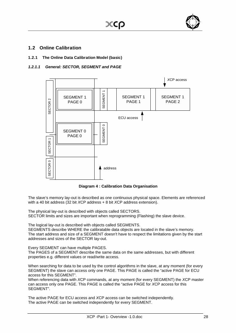
1.2.1.1 General: SECTOR, SEGMENT and PAGE
...
...SEGMENT 1PAGE 0
SEGMENT 1PAGE 1
SEGMENT 1PAGE 2
SEGMENT 0PAGE 0
SEC
TOR
0SE
CTO
R 1
SEC
TOR
2
SEG
MEN
T 0
SEG
MEN
T 1
ECU access
XCP access
address
Diagram 4 : Calibration Data Organisation
The slave’s memory lay-out is described as one continuous physical space. Elements are referenced with a 40 bit address (32 bit XCP address + 8 bit XCP address extension). The physical lay-out is described with objects called SECTORS. SECTOR limits and sizes are important when reprogramming (Flashing) the slave device. The logical lay-out is described with objects called SEGMENTS. SEGMENTS describe WHERE the calibratable data objects are located in the slave’s memory. The start address and size of a SEGMENT doesn’t have to respect the limitations given by the start addresses and sizes of the SECTOR lay-out. Every SEGMENT can have multiple PAGES. The PAGES of a SEGMENT describe the same data on the same addresses, but with different properties e.g. different values or read/write access. When searching for data to be used by the control algorithms in the slave, at any moment (for every SEGMENT) the slave can access only one PAGE. This PAGE is called the “active PAGE for ECU access for this SEGMENT”. When referencing data with XCP commands, at any moment (for every SEGMENT) the XCP master can access only one PAGE. This PAGE is called the “active PAGE for XCP access for this SEGMENT”. The active PAGE for ECU access and XCP access can be switched independently. The active PAGE can be switched independently for every SEGMENT.

XCP -Part 1- Overview -1.0.doc 29
1.2.1.2 Logical lay-out: SEGMENT The logical lay-out of the slave’s memory is described with objects called SEGMENTS. SEGMENTS describe WHERE the calibratable data objects are located in the slave’s memory. The start address and size of a SEGMENT doesn’t have to respect the limitations given by the start addresses and sizes of the SECTOR lay-out (ref. Flashing). A SEGMENT is described with the normal ASAM MCD2 keyword MEMORY_SEGMENT which contains information like Name, Address, Size and Offsets for Mirrored Segments. The XCP specific information is inside an IF_DATA section. For having a 40 bit address space, every SEGMENT is having an address extension which is valid for all calibratable objects that are located within this SEGMENT. XCP references a SEGMENT by its SEGMENT_NUMBER. Within one and the same XCP slave device, the range for the SEGMENT_NUMBER starts from 0 and has to be continuous.
SEGMENT_NUMBER [0,1,..255]
XCP -Part 1- Overview -1.0.doc 30
1.2.1.3 Accessability: PAGE Every SEGMENT can have multiple PAGES. The PAGEs of a SEGMENT describe the same data on the same addresses, but with different properties e.g. different values or read/write access. Every SEGMENT always at least has to have 1 PAGE, called PAGE 0. The slave always has to initialize all its PAGEs for all its SEGMENTs. PAGE 0 of the INIT_SEGMENT of a PAGE contains the initial data for a PAGE. With GET_CAL_PAGE, the master can get the current active PAGEs for XCP and ECU access of the slave. The ECU_ACCESS_x flags indicate whether and how the ECU can access this page. If the ECU can access this PAGE, the ECU_ACCESS_x flags indicate whether the ECU can access this PAGE only if the XCP master does NOT access this PAGE at the same time, only if the XCP master accesses this page at the same time, or the ECU doesn’t care whether the XCP master accesses this page at the same time or not. The XCP_x_ACCESS_y flags indicate whether and how the XCP master can access this page. The flags make a distinction for the XCP_ACCESS_TYPE depending on the kind of access the XCP master can have on this page (READABLE and/or WRITEABLE). If the XCP master can access this PAGE, the XCP_READ_ACCESS_x flags indicate whether the XCP master can read from this PAGE only if the ECU does NOT access this PAGE at the same time, only if the ECU accesses this page at the same time, or the XCP master doesn’t need to care whether the ECU accesses this page at the same time or not. If the XCP master can access this PAGE, the XCP_WRITE_ACCESS_x flags indicate whether the XCP master can write to this PAGE only if the ECU does NOT access this PAGE at the same time, only if the ECU accesses this page at the same time, or the XCP master doesn’t need to care whether the ECU accesses this page at the same time or not. For every SEGMENT the numbering of the PAGEs through PAGE_NUMBER restarts from 0
PAGE_NUMBER(Segment j) [0,1,..255]
XCP -Part 1- Overview -1.0.doc 31
1.2.2 The Online Data Calibration Model (optional features)
1.2.2.1 Calibration Data Page Switching If the slave supports the optional commands GET_CAL_PAGE and SET_CAL_PAGE, page switching is supported. When searching for data to be used by the control algorithms in the slave, at any moment (for every SEGMENT) the slave can access only one PAGE. This PAGE is called the “active PAGE for ECU access for this SEGMENT”. When referencing data with XCP commands, at any moment (for every SEGMENT) the XCP master can access only one PAGE. This PAGE is called the “active PAGE for XCP access for this SEGMENT”. With GET_CAL_PAGE, the master can request the slave to answer the current active PAGE for ECU or XCP access for this SEGMENT. With SET_CAL_PAGE, the master can set the current active PAGE for ECU or XCP access for this SEGMENT. The master has the full control for switching the pages. The slave can not switch its pages autonomously. The active PAGE for ECU access and XCP access can be switched independently. The active PAGE can be switched independently for every SEGMENT. The master also can switch all SEGMENTS synchronously to the same PAGE. The master has to respect the constraints given by the XCP_ACCESS_TYPE and ECU_ACCESS_TYPE.
XCP -Part 1- Overview -1.0.doc 32
1.2.2.2 Advanced features
1.2.2.2.1 Calibration Data Page Freezing The FREEZE_SUPPORTED flag in PAG_PROPERTIES at GET_PAG_PROCESSOR_INFO indicates that all SEGMENTS can be put in FREEZE mode. With SET_SEGMENT_MODE the master can select a SEGMENT for freezing. With GET_SEGMENT_MODE the master can identify whether a SEGMENT has been selected for FREEZING. With STORE_CAL_REQ in SET_REQUEST, the master requests the slave to save calibration data into non-volatile memory. For each SEGMENT that is in FREEZE mode, the slave has to save the current active XCP PAGE for this SEGMENT into PAGE 0 of the INIT_SEGMENT of this PAGE. The STORE_CAL_REQ bit obtained by GET_STATUS will be reset by the slave, when the request is fulfilled. The slave device may indicate this by transmitting an EV_STORE_CAL event packet.
XCP -Part 1- Overview -1.0.doc 33
1.2.3 The Online Data Calibration actions
1.2.3.1 Addressing The slave’s memory lay-out is described as one continuous physical space. Elements are referenced with a 40 bit address (32 bit XCP address + 8 bit XCP address extension). The address extension is taken from the SEGMENT to which the currently referenced address belongs. The address range at MEMORY_SEGMENT describes the addresses from which the master can generate a file that can be programmed into the slave and then will result in a normal operating slave. For checking whether a CHARACTERISTIC belongs to a MEMORY_SEGMENT, the master has to take the address written at CHARACTERISTIC, if applicable apply the ECU_CALIBRATION_OFFSET and if applicable the dereferencing of the NearPointer and then check this resulting address to be part of the MEMORY_SEGMENT. For the (destination) address used in SET_MTA , SHORT_UPLOAD and SHORT_DOWNLOAD, the master has to take the address as calculated above (take address at CHARACTERISTIC, apply ECU_CALIBRATION_OFFSET, dereference) and if applicable apply an ADDRESS_MAPPING from the calculated (source) address to a mapped (destination) address. ADDRESS_MAPPING can be different for different parts of a SEGMENT.
*(x)
A2L_addressat CHARACTERISTIC
ECU_CALIBRATION_OFFSET
Address in HEX file for flashing Working Base addressAddress is located in
MEMORY_SEGMENT
YES
+
+
+
+ +
+
+
-
NO
Near pointer ?
ADDRESS_MAPPINGFrom
To
XCP Calibrating
XCP Flashing
Diagram 5 : address calculation
XCP -Part 1- Overview -1.0.doc 34
1.2.3.2 Master - slave The slave has to support checksum calculation on all address ranges that are described with SECTORS or SEGMENTS. Checksum calculation has to be possible for all PAGEs that have XCP_ACCESS_ALLOWED. If a PAGE is READABLE by the XCP master, the master can access this PAGE with the commands UPLOAD and SHORT_UPLOAD, in standard mode and if supported in block mode. If a PAGE is WRITEABLE by the XCP master, the master can access this PAGE with the commands SHORT_DOWNLOAD and DOWNLOAD_MAX in standard mode. If a PAGE is WRITEABLE by the XCP master, the master can access this PAGE with the commands DOWNLOAD and if block mode supported with DOWNLOAD_NEXT. If a PAGE is WRITEABLE by the XCP master, the master can access this PAGE with the command MODIFY_BITS which allows to modify bits in an atomic way.

XCP -Part 1- Overview -1.0.doc 35
1.2.3.3 Page – page If the XCP slave device has more than one PAGE, the master can copy the data from one PAGE to another with COPY_CAL_PAGE. In principal any PAGE of any SEGMENT can be copied to any PAGE of any SEGMENT. However, restrictions might be possible. The slave indicates this by ERR_PAGE_NOT_VALID, ERR_SEGMENT_NOT_VALID or ERR_WRITE_PROTECTED.

XCP -Part 1- Overview -1.0.doc 36
1.3 Flash programming
1.3.1 The Flashing Model
1.3.1.1 Physical lay-out: SECTOR The physical lay-out of the slave’s memory is described with objects called SECTORS. SECTOR start addresses and sizes are important when reprogramming (Flashing) the slave device. A SECTOR is referenced by a SECTOR_NUMBER. Within one and the same XCP slave device, the range for the SECTOR_NUMBER starts from 0 and has to be continuous.
SECTOR_NUMBER [0,1,..255]
XCP -Part 1- Overview -1.0.doc 37
1.3.1.2 General: In principle the complete flash process can be divided into three steps. It depends on the point of view, whether the individual use case needs all of them:
1. administration before (for example version control) 2. original flash process (‘only’ the programming actions) 3. administration below (for example version or checksum control)
The XCP protocol deals with these steps in different ways. The commands for the original flash process are the focus of XCP. XCP offers special programming commands. The project specific use of all the commands must be specified in a project specific “programming flow control”. This document specifies no standard for this additional description file. In practice every project needs a project specific agreement between the ECU and the tool supplier. List without any sequence definition:
PROGRAM_START PROGRAM_CLEAR PROGRAM_FORMAT PROGRAM (Loop) It is also possible to use a block transfer mode optionally. PROGRAM_VERIFY PROGRAM_RESET
Usually administration before means version control before the original flash process has been started. This examination checks inside the tool whether the new flash content fits to the ECU. Therefore the tools needs identification information of the ECU and of the new flash content. XCP doesn’t support special version control commands for the flash process. In practice the administration actions are very project specific and it depends on the ECU, which services are necessary. The ECU functional description can specify with which standard XCP commands a version control before could be done. The actions of the version control below can be done inside the ECU. XCP supports some flexible commands. The original flash process can be done with different concepts. The XCP protocol supports two different flash access methods. They are called the “absolute” and the “functional” access modes. Both methods use the same commands with sometimes different parameters. It is possible to mix, i.e. to use a different access method for the delete phase in comparison to the programming phase. The recommended concept is based on the available address and memory information and specified in the project specific programming flow control.
XCP -Part 1- Overview -1.0.doc 38
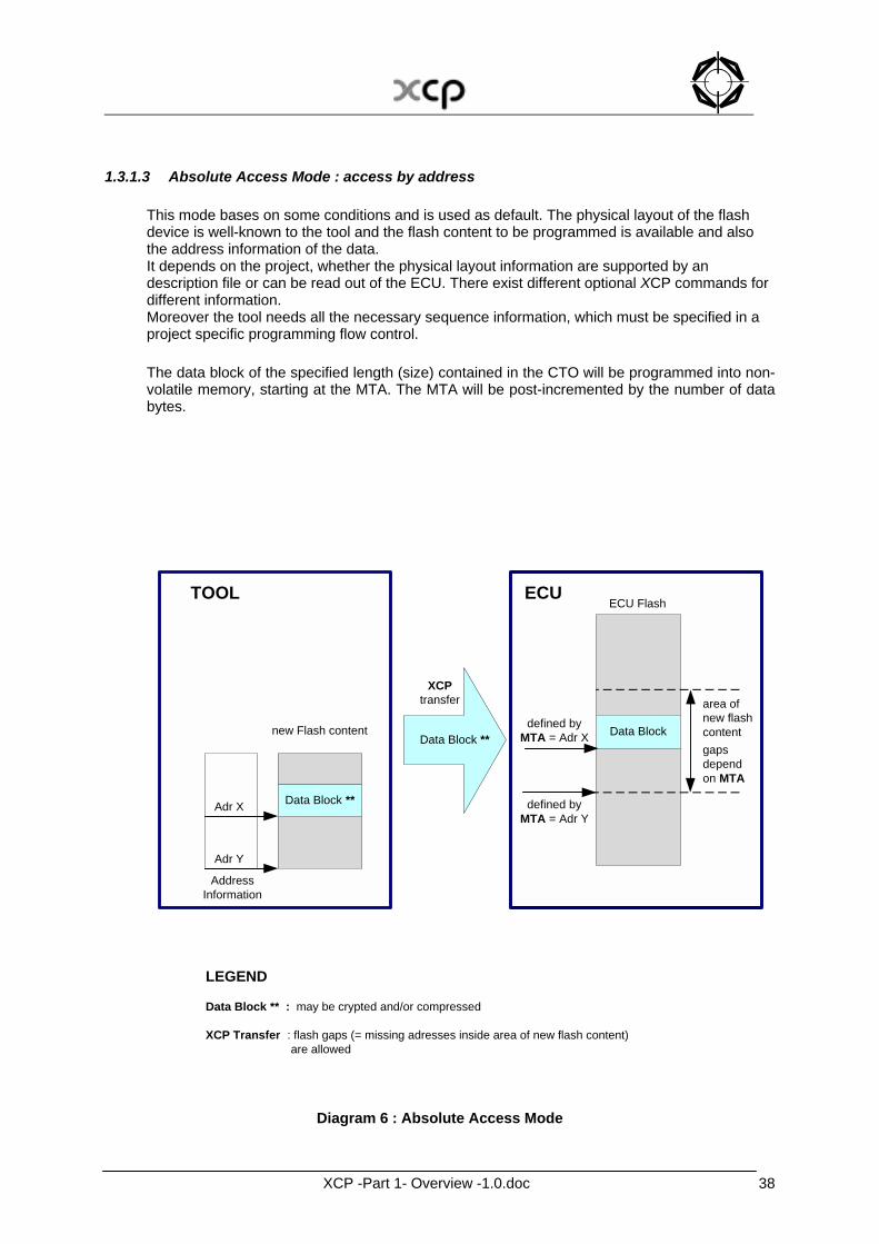
1.3.1.3 Absolute Access Mode : access by address This mode bases on some conditions and is used as default. The physical layout of the flash device is well-known to the tool and the flash content to be programmed is available and also the address information of the data. It depends on the project, whether the physical layout information are supported by an description file or can be read out of the ECU. There exist different optional XCP commands for different information. Moreover the tool needs all the necessary sequence information, which must be specified in a project specific programming flow control. The data block of the specified length (size) contained in the CTO will be programmed into non-volatile memory, starting at the MTA. The MTA will be post-incremented by the number of data bytes.
Data Block **
new Flash content
AddressInformation
Adr X
Adr Y
TOOL ECU
Data Block
ECU Flash
defined byMTA = Adr X
defined byMTA = Adr Y
area ofnew flashcontentgapsdependon MTA
Data Block **
XCPtransfer
LEGEND
Data Block ** : may be crypted and/or compressed
XCP Transfer : flash gaps (= missing adresses inside area of new flash content) are allowed
Diagram 6 : Absolute Access Mode
XCP -Part 1- Overview -1.0.doc 39
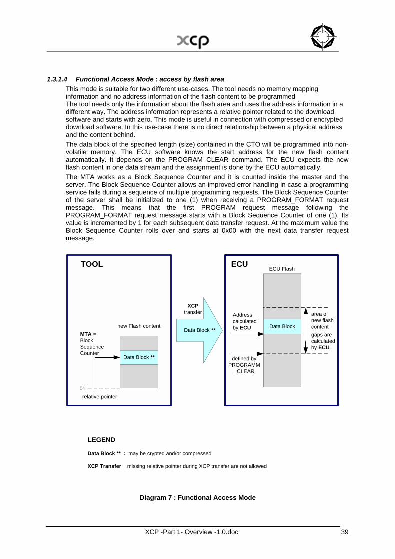
1.3.1.4 Functional Access Mode : access by flash area This mode is suitable for two different use-cases. The tool needs no memory mapping information and no address information of the flash content to be programmed The tool needs only the information about the flash area and uses the address information in a different way. The address information represents a relative pointer related to the download software and starts with zero. This mode is useful in connection with compressed or encrypted download software. In this use-case there is no direct relationship between a physical address and the content behind. The data block of the specified length (size) contained in the CTO will be programmed into non-volatile memory. The ECU software knows the start address for the new flash content automatically. It depends on the PROGRAM_CLEAR command. The ECU expects the new flash content in one data stream and the assignment is done by the ECU automatically. The MTA works as a Block Sequence Counter and it is counted inside the master and the server. The Block Sequence Counter allows an improved error handling in case a programming service fails during a sequence of multiple programming requests. The Block Sequence Counter of the server shall be initialized to one (1) when receiving a PROGRAM_FORMAT request message. This means that the first PROGRAM request message following the PROGRAM_FORMAT request message starts with a Block Sequence Counter of one (1). Its value is incremented by 1 for each subsequent data transfer request. At the maximum value the Block Sequence Counter rolls over and starts at 0x00 with the next data transfer request message.
Data Block **
new Flash content
relative pointer
MTA =BlockSequenceCounter
01
TOOL ECU
Data Block
ECU Flash
Addresscalculatedby ECU
defined byPROGRAMM
_CLEAR
area ofnew flashcontentgaps arecalculatedby ECU
Data Block **
XCPtransfer
LEGEND
Data Block ** : may be crypted and/or compressed
XCP Transfer : missing relative pointer during XCP transfer are not allowed
Diagram 7 : Functional Access Mode
XCP -Part 1- Overview -1.0.doc 40
The behaviour is similar to ISO 14229-1 (Road vehicles - Diagnostic services - Part 1: Specification and requirements) and ISO 15765-3 (Road vehicles - Diagnostics on controller area network (CAN) - Part 3: Implementation of diagnostic services) . If a PROGRAM request is correctly received and processed in the slave, but the positive response message does not reach the master, then the master would determine an application layer timeout and would repeat the same request (including the same Block Sequence Counter). The slave would receive the repeated PROGRAM request and could determine based on the included Block Sequence Counter, that this PROGRAM request is repeated. The slave would send the positive response message immediately without writing the data once again into its memory. If the PROGRAM request is not received correctly in the slave, then the slave would not send a positive response message. The master would determine an application layer timeout and would repeat the same request (including the same Block Sequence Counter). The slave would receive the repeated PROGRAM request and could determine based on the included Block Sequence Counter that this is a new PROGRAM request. The slave would process the service and would send the positive response message. It is optionally possible to change to the absolute access mode at the end of the flash session. Affected Commands PROGRAM_CLEAR, PROGRAM_FORMAT, PROGRAM, SET_MTA
XCP -Part 1- Overview -1.0.doc 41
1.3.1.5 Checksum Control and Program Verify After the original flash process a version control is helpful. This action checks whether the new flash content fits to the rest of the flash. In practice exists different methods, but XCP supports only a checksum control and the start of internal test routines. The checksum method can be done with the standard checksum command (examination inside the tool). On the other hand XCP supports an examination inside the slave. The tool can start slave internal test routines and send verification values to the slave. Affected Commands BUILD_CHECKSUM, PROGRAM_VERIFY

XCP -Part 1- Overview -1.0.doc 42
1.3.1.6 End of Flash Session The end of the overall programming sequence is indicated by a PROGRAM_RESET command. The slave device will go to disconnected state. Usually a hardware reset of the slave device is executed. Affected Commands PROGRAM_RESET
XCP -Part 1- Overview -1.0.doc 43
2 The XCP Protocol
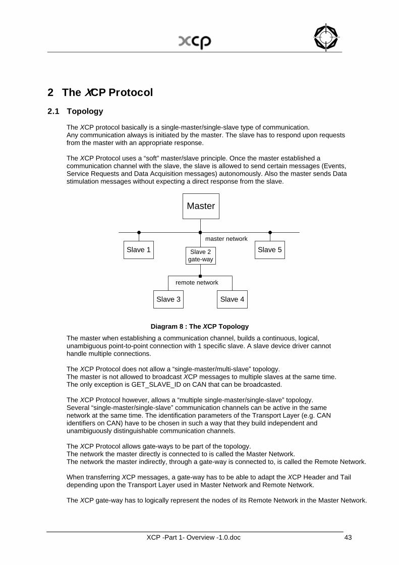
2.1 Topology The XCP protocol basically is a single-master/single-slave type of communication. Any communication always is initiated by the master. The slave has to respond upon requests from the master with an appropriate response. The XCP Protocol uses a “soft” master/slave principle. Once the master established a communication channel with the slave, the slave is allowed to send certain messages (Events, Service Requests and Data Acquisition messages) autonomously. Also the master sends Data stimulation messages without expecting a direct response from the slave.
Slave 1
Master
Slave 2gate-way
Slave 5
Slave 3 Slave 4
master network
remote network
Diagram 8 : The XCP Topology The master when establishing a communication channel, builds a continuous, logical, unambiguous point-to-point connection with 1 specific slave. A slave device driver cannot handle multiple connections. The XCP Protocol does not allow a “single-master/multi-slave” topology. The master is not allowed to broadcast XCP messages to multiple slaves at the same time. The only exception is GET_SLAVE_ID on CAN that can be broadcasted. The XCP Protocol however, allows a “multiple single-master/single-slave” topology. Several “single-master/single-slave” communication channels can be active in the same network at the same time. The identification parameters of the Transport Layer (e.g. CAN identifiers on CAN) have to be chosen in such a way that they build independent and unambiguously distinguishable communication channels. The XCP Protocol allows gate-ways to be part of the topology. The network the master directly is connected to is called the Master Network. The network the master indirectly, through a gate-way is connected to, is called the Remote Network. When transferring XCP messages, a gate-way has to be able to adapt the XCP Header and Tail depending upon the Transport Layer used in Master Network and Remote Network. The XCP gate-way has to logically represent the nodes of its Remote Network in the Master Network.
XCP -Part 1- Overview -1.0.doc 44
Example: Master Network = CAN 500000 bps Remote Network = CAN 250000 bps
Master with Slave 1 Master sends with CAN-Id = 0x100 on Master Network Slave 1 sends with CAN-Id = 0x110 on Master Network Master with Slave 2 (Slave 2 directly) Master sends with CAN-Id = 0x200 on Master Network Slave 2 sends with CAN-Id = 0x210 on Master Network Master with Slave 3 (Slave 2 as gate-way) Master sends with CAN-Id = 0x300 to Slave 2 on Master Network Slave 2 sends with CAN-Id = 0x100 to Slave 3 on Remote Network Slave 3 sends with CAN-Id = 0x110 to Slave 2 on Remote Network Slave 2 sends with CAN-Id = 0x310 on Master Network
XCP -Part 1- Overview -1.0.doc 45
2.2 The XCP communication models
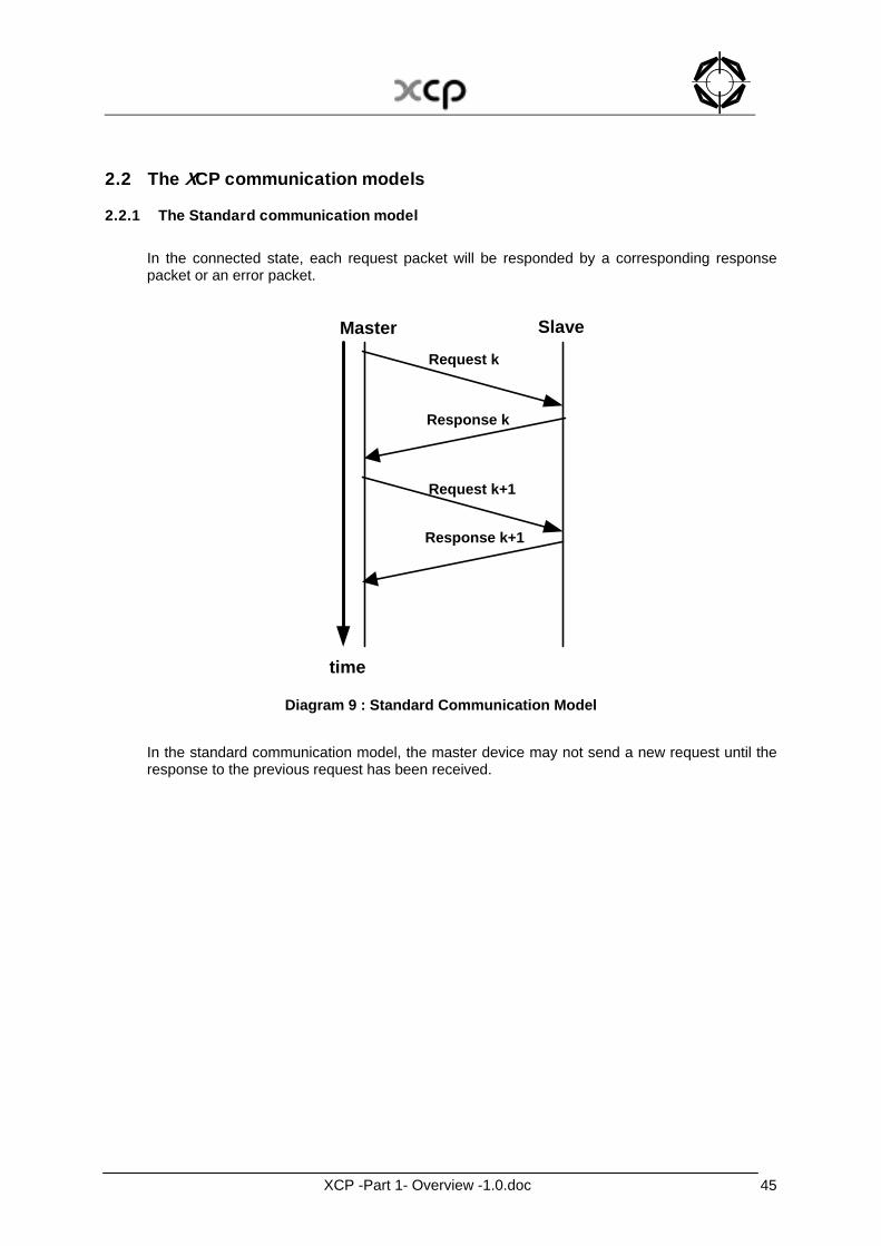
2.2.1 The Standard communication model In the connected state, each request packet will be responded by a corresponding response packet or an error packet.
time
Request k
Response k
Master Slave
Request k+1
Response k+1
Diagram 9 : Standard Communication Model
In the standard communication model, the master device may not send a new request until the response to the previous request has been received.
XCP -Part 1- Overview -1.0.doc 46
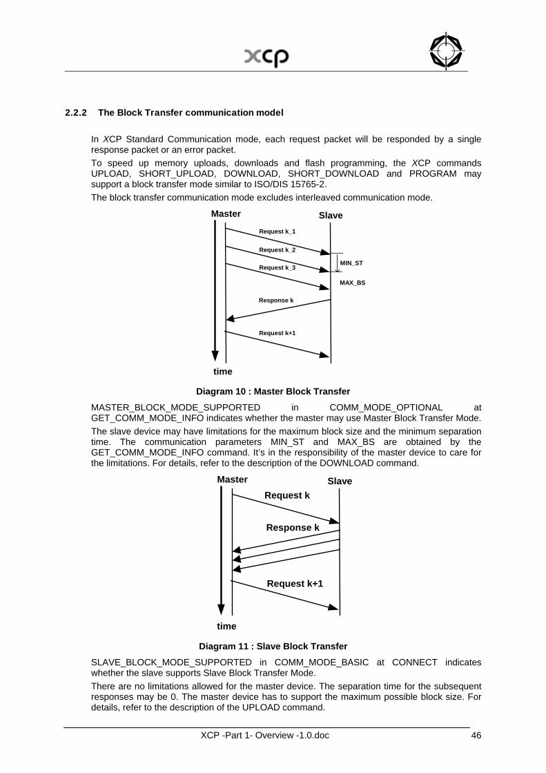
2.2.2 The Block Transfer communication model In XCP Standard Communication mode, each request packet will be responded by a single response packet or an error packet. To speed up memory uploads, downloads and flash programming, the XCP commands UPLOAD, SHORT_UPLOAD, DOWNLOAD, SHORT_DOWNLOAD and PROGRAM may support a block transfer mode similar to ISO/DIS 15765-2. The block transfer communication mode excludes interleaved communication mode.
time
Request k+1
Response k
Master Slave
MIN_STRequest k_3
Request k_2
MAX_BS
Request k_1
Diagram 10 : Master Block Transfer
MASTER_BLOCK_MODE_SUPPORTED in COMM_MODE_OPTIONAL at GET_COMM_MODE_INFO indicates whether the master may use Master Block Transfer Mode. The slave device may have limitations for the maximum block size and the minimum separation time. The communication parameters MIN_ST and MAX_BS are obtained by the GET_COMM_MODE_INFO command. It’s in the responsibility of the master device to care for the limitations. For details, refer to the description of the DOWNLOAD command.
time
Request k
Response k
Master Slave
Request k+1
Diagram 11 : Slave Block Transfer
SLAVE_BLOCK_MODE_SUPPORTED in COMM_MODE_BASIC at CONNECT indicates whether the slave supports Slave Block Transfer Mode. There are no limitations allowed for the master device. The separation time for the subsequent responses may be 0. The master device has to support the maximum possible block size. For details, refer to the description of the UPLOAD command.
XCP -Part 1- Overview -1.0.doc 47
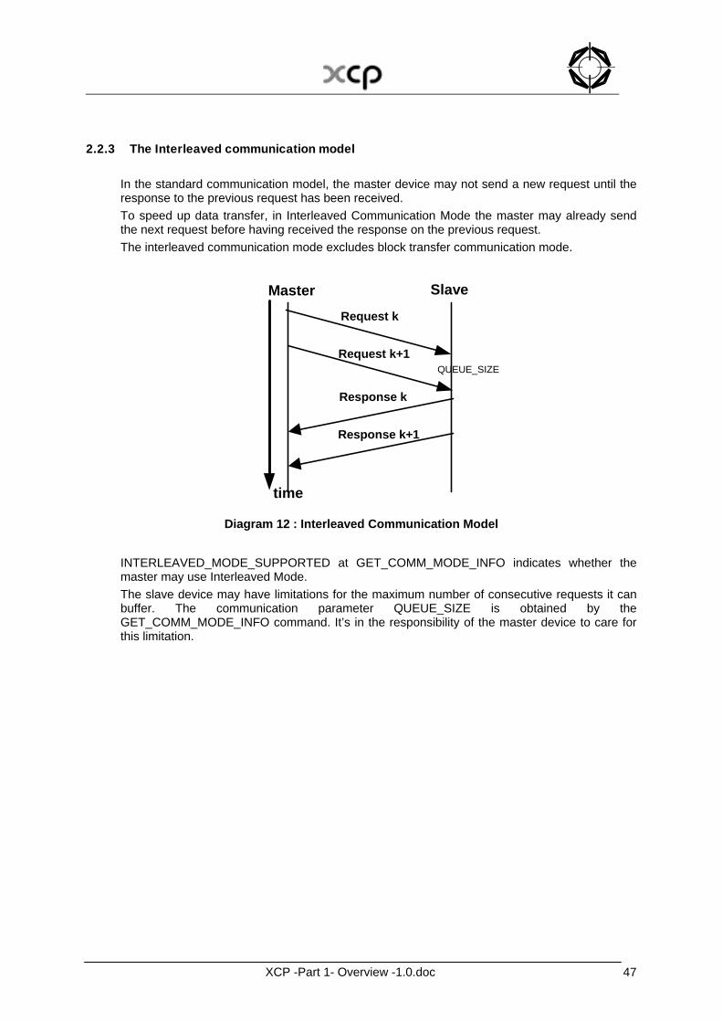
2.2.3 The Interleaved communication model In the standard communication model, the master device may not send a new request until the response to the previous request has been received. To speed up data transfer, in Interleaved Communication Mode the master may already send the next request before having received the response on the previous request. The interleaved communication mode excludes block transfer communication mode.
time
Request k
Response k
Master Slave
Request k+1
Response k+1
QUEUE_SIZE
Diagram 12 : Interleaved Communication Model
INTERLEAVED_MODE_SUPPORTED at GET_COMM_MODE_INFO indicates whether the master may use Interleaved Mode. The slave device may have limitations for the maximum number of consecutive requests it can buffer. The communication parameter QUEUE_SIZE is obtained by the GET_COMM_MODE_INFO command. It’s in the responsibility of the master device to care for this limitation.
XCP -Part 1- Overview -1.0.doc 48
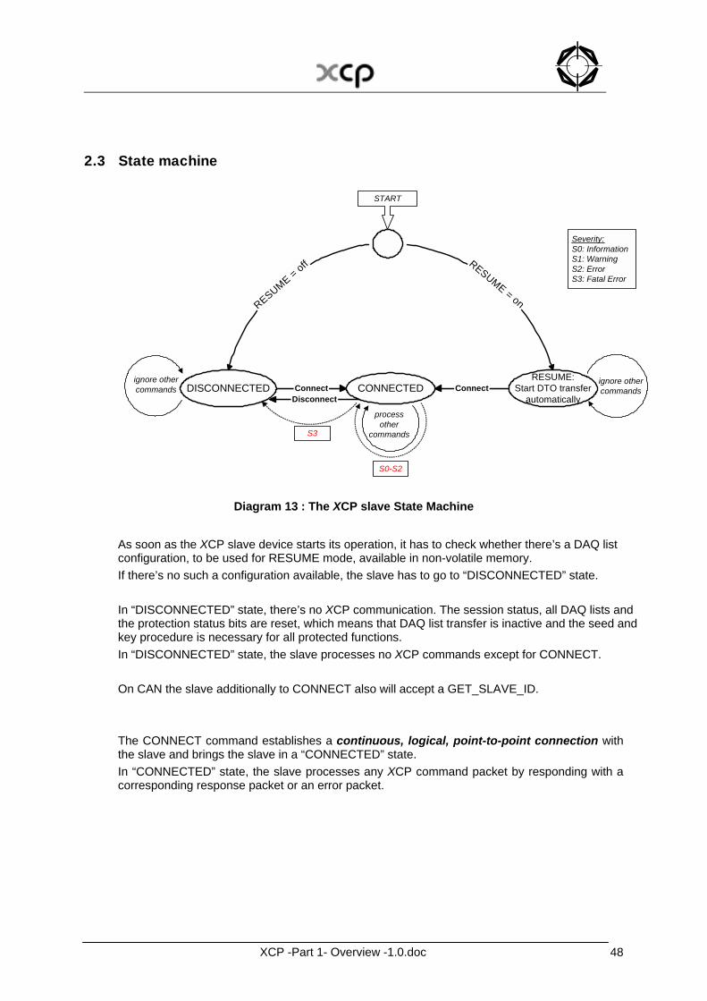
2.3 State machine
ConnectDisconnect
ConnectDISCONNECTEDRESUME:
Start DTO transferautomatically
RESUME = off RESUME = on
CONNECTED
START
processother
commands
ignore othercommands
ignore othercommands
S0-S2
S3
Severity:S0: InformationS1: WarningS2: ErrorS3: Fatal Error
Diagram 13 : The XCP slave State Machine As soon as the XCP slave device starts its operation, it has to check whether there’s a DAQ list configuration, to be used for RESUME mode, available in non-volatile memory. If there’s no such a configuration available, the slave has to go to “DISCONNECTED” state. In “DISCONNECTED” state, there’s no XCP communication. The session status, all DAQ lists and the protection status bits are reset, which means that DAQ list transfer is inactive and the seed and key procedure is necessary for all protected functions. In “DISCONNECTED” state, the slave processes no XCP commands except for CONNECT. On CAN the slave additionally to CONNECT also will accept a GET_SLAVE_ID. The CONNECT command establishes a continuous, logical, point-to-point connection with the slave and brings the slave in a “CONNECTED” state. In “CONNECTED” state, the slave processes any XCP command packet by responding with a corresponding response packet or an error packet.
XCP -Part 1- Overview -1.0.doc 49
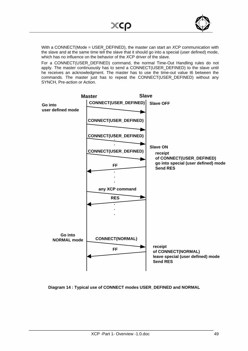
With a CONNECT(Mode = USER_DEFINED), the master can start an XCP communication with the slave and at the same time tell the slave that it should go into a special (user defined) mode, which has no influence on the behavior of the XCP driver of the slave. For a CONNECT(USER_DEFINED) command, the normal Time-Out Handling rules do not apply. The master continuously has to send a CONNECT(USER_DEFINED) to the slave until he receives an acknowledgment. The master has to use the time-out value t6 between the commands. The master just has to repeat the CONNECT(USER_DEFINED) without any SYNCH, Pre-action or Action.
Master SlaveGo intouser defined mode
Slave OFF
Slave ON
.
.
.
receiptof CONNECT(USER_DEFINED)go into special (user defined) modeSend RES
RES
.
.
.
any XCP command
.
.
.
Go intoNORMAL mode CONNECT(NORMAL)
FF
FF
CONNECT(USER_DEFINED)
receiptof CONNECT(NORMAL)leave special (user defined) modeSend RES
CONNECT(USER_DEFINED)
CONNECT(USER_DEFINED)
CONNECT(USER_DEFINED)
Diagram 14 : Typical use of CONNECT modes USER_DEFINED and NORMAL
XCP -Part 1- Overview -1.0.doc 50
With a CONNECT(Mode = NORMAL), the master can start an XCP communication with the slave. In “CONNECTED” state, the slave has to acknowledge a new CONNECT and handle it like a CONNECT command to a disconnected device. If the slave when starting its operation detects that there’s a DAQ list configuration, to be used for RESUME mode, available in non-volatile memory , the slave has to go to the ” RESUME” state. In “RESUME”, the slave automatically has to start those DAQ lists that are stored in non-volatile memory and that are to be used for RESUME mode (ref. Description of RESUME mode). In “RESUME”, the slave processes no XCP commands except for CONNECT. In “RESUME” state, the slave has to acknowledge a CONNECT and handle it like a CONNECT command to a disconnected device, but keep the current DTO transfer running. In “CONNECTED” state, if the master sends a DISCONNECT command, the slave goes to “DISCONNECTED” state. If an error occurs with severity S0-S2, the slave will not change its state. If an error occurs with severity S3 “Fatal error”, this will bring the slave to the “DISCONNECTED” state.
XCP -Part 1- Overview -1.0.doc 51
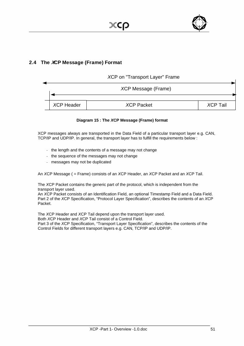
2.4 The XCP Message (Frame) Format
XCP PacketXCP Header
XCP Message (Frame)
XCP on "Transport Layer" Frame
XCP Tail
Diagram 15 : The XCP Message (Frame) format XCP messages always are transported in the Data Field of a particular transport layer e.g. CAN, TCP/IP and UDP/IP. In general, the transport layer has to fulfill the requirements below :
- the length and the contents of a message may not change - the sequence of the messages may not change - messages may not be duplicated
An XCP Message ( = Frame) consists of an XCP Header, an XCP Packet and an XCP Tail. The XCP Packet contains the generic part of the protocol, which is independent from the transport layer used. An XCP Packet consists of an Identification Field, an optional Timestamp Field and a Data Field. Part 2 of the XCP Specification, “Protocol Layer Specification”, describes the contents of an XCP Packet. The XCP Header and XCP Tail depend upon the transport layer used. Both XCP Header and XCP Tail consist of a Control Field. Part 3 of the XCP Specification, “Transport Layer Specification”, describes the contents of the Control Fields for different transport layers e.g. CAN, TCP/IP and UDP/IP.

XCP -Part 1- Overview -1.0.doc 52
3 The Limits of Performance
3.1 Generic performance parameters MAX_CTO shows the maximum length of a CTO packet in bytes. MAX_DTO shows the maximum length of a DTO packet in bytes.
Name Type Representation Range of value MAX_CTO Parameter BYTE 0x08 – 0xFF MAX_DTO Parameter WORD 0x0008 – 0xFFFF
The range of both protocol parameters can be smaller, depending on the used transport layer.
XCP -Part 1- Overview -1.0.doc 53
3.2 DAQ/STIM specific performance parameters MAX_EVENT_CHANNEL indicates the number of event channels on the XCP slave. An event channel is identified by a number called EVENT_CHANNEL_NUMBER. Counting starts at zero.
Name Type Representation Range of value MAX_EVENT_CHANNEL Parameter WORD 0x0000 – 0xFFFF MAX_EVENT_CHANNEL_ABS Constant WORD 0xFFFF EVENT_CHANNEL_NUMBER Parameter WORD 0x0000 – 0xFFFE EVENT_CHANNEL_NUMBER_MAX Parameter WORD MAX_EVENT_CHANNEL –1EVENT_CHANNEL_NUMBER_MAX_ABS Constant WORD 0xFFFE
MAX_DAQ indicates the number of DAQ lists on the XCP slave. A DAQ list is identified by a number called DAQ_LIST_NUMBER. Counting starts at zero. MIN_DAQ indicates the number of predefined, read only DAQ lists on the XCP slave. DAQ_COUNT indicates the number of DAQ lists for dynamic configuration.
Name Type Representation Range of value MAX_DAQ Parameter WORD 0x0000 – 0xFFFF MAX_DAQ_ABS Constant WORD 0xFFFF DAQ_COUNT Parameter WORD 0x0000 – 0xFFFF MIN_DAQ Parameter BYTE 0x00 – 0xFF DAQ_LIST_NUMBER Parameter WORD 0x0000 – 0xFFFE
MAX_ODT_ENTRIES indicates the maximum amount of entries into an ODT of the XCP slave. ODT_ENTRIES_COUNT indicates the amount of entries into an ODT using dynamic DAQ list configuration. An entry is identified by a number called ODT_ENTRY_NUMBER. Counting starts at zero.
Name Type Representation Range of value MAX_ODT_ENTRIES Parameter BYTE 0x00 – 0xFF ODT_ENTRIES_COUNT Parameter BYTE 0x00 – 0xFF ODT_ENTRY_NUMBER Parameter BYTE 0x00 – 0xFE
XCP -Part 1- Overview -1.0.doc 54
3.2.1 DAQ specific parameters MAX_ODT indicates the maximum amount of ODTs of the XCP slave. ODT_COUNT indicates the amount of ODTs of a DAQ list using dynamic DAQ list configuration. An ODT is identified by a number called ODT_number. Counting starts at zero.
Name Type Representation Range of value MAX_ODT Parameter BYTE 0x00 – 0xFC
ODT_COUNT Parameter BYTE 0x00 – 0xFC ODT_NUMBER Parameter BYTE 0x00 – 0xFB
3.2.2 STIM specific parameters MAX_ODT indicates the maximum amount of ODTs of the XCP slave. ODT_COUNT indicates the amount of ODTs of a DAQ list using dynamic DAQ list configuration. An ODT is identified by a number called ODT_number. Counting starts at zero.
Name Type Representation Range of value MAX_ODT Parameter BYTE 0x00 – 0xC0 ODT_COUNT Parameter BYTE 0x00 – 0xC0 ODT_NUMBER Parameter BYTE 0x00 – 0xBF
XCP -Part 1- Overview -1.0.doc 55
4 Versioning
4.1 The XCP Protocol Layer Version Number Part 2 of the XCP Specification, “Protocol Layer Specification”, describes the contents of an XCP Packet. The XCP Packet is the generic part of the protocol that is independent from the Transport Layer used. The XCP Protocol Layer Version Number indicates the version of the Protocol Layer Specification. The XCP Protocol Layer Version Number is a 16-bit value. If the Protocol Layer is modified in such a way that a functional modification in the slave’s driver software is needed, the higher byte of the XCP Protocol Layer Version Number will be incremented. This could be the case e.g. when modifying the parameters of an existing command or adding a new command to the specification. If the Protocol Layer is modified in such a way that it has no direct influence on the slave’s driver software, the lower byte of the XCP Protocol Layer Version Number will be incremented. This could be the case e.g. when rephrasing the explaining text or modifying the AML description. The slave only returns the most significant byte of the XCP Protocol Layer Version Number in the response upon CONNECT.
XCP -Part 1- Overview -1.0.doc 56
4.2 The XCP Transport Layer Version Number Part 3 of the XCP Specification, “Transport Layer Specification”, describes the contents of the Control Fields for different transport layers e.g. CAN, TCP/IP and UDP. Part 3 of the XCP Specification also describes possible additional Packets for a specific Transport Layer. Independent from Part 2, every Part 3 has its own XCP Transport Layer Version Number. The XCP Transport Layer Version Number indicates the version of a specific Part 3 of the specification. The XCP Transport Layer Version Number is a 16-bit value. If a specific Part 3 is modified in such a way that a functional modification in the slave’s driver software is needed, the higher byte of its XCP Transport Layer Version Number will be incremented. This could be the case e.g. when modifying the parameters of an existing command or adding a new command to the specification. If a specific Part 3 is modified in such a way that it has no direct influence on the slave’s driver software, the lower byte of its XCP Transport Layer Version Number will be incremented. This could be the case e.g. when rephrasing the explaining text or modifying the AML description. The slave only returns the most significant byte of the XCP Transport Layer Version Number for the current Transport Layer in the response upon CONNECT.
XCP -Part 1- Overview -1.0.doc 57
4.3 The Compatibility Matrix The main.a2l that describes a slave that supports XCP on different Transport Layers, includes an XCP_definitions.aml that contains a reference to a certain version of Protocol Layer Specification and (a) reference(s) to (a) certain version(s) of Transport Layer Specification(s). If a certain version of the Protocol Layer Specification needs a certain version of a Transport Layer Specification, this will be mentioned as prerequisite in the Protocol Layer Specification. If a certain version of a Transport Layer Specification needs a certain version of Protocol Layer Specification, this will be mentioned as prerequisite in the Transport Layer Specification. The Compatibility Matrix at
www.asam.net under “Standards/ ASAM MCD/ I. Current specifications” gives an overview of the allowed combinations of XCP Protocol Layer Version Number and XCP Transport Layer Version Number.

XCP -Part 1- Overview -1.0.doc 58
ASAM e. V.
Arnikastraße 2 D - 85635 Hoehenkirchen
Germany
Tel.: (+49) 8102 / 895317 Fax.: (+49) 8102 / 895310 E-mail: [email protected] Internet: www.asam.net