Embed Size (px)
Citation preview
Fujitsu M10/SPARC M10 Systems
Product Notes for XCP Version 2050
Manual Code: C120-E703-02ENOctober 2013
Copyright © 2007, 2013, Fujitsu Limited. All rights reserved.
Oracle and/or its affiliates provided technical input and review on portions of this material.
Oracle and/or its affiliates and Fujitsu Limited each own or control intellectual property rights relating to products and technology described in this document, and such products,
technology and this document are protected by copyright laws, patents, and other intellectual property laws and international treaties.
This document and the product and technology to which it pertains are distributed under licenses restricting their use, copying, distribution, and decompilation. No part of such
product or technology, or of this document, may be reproduced in any form by any means without prior written authorization of Oracle and/or its affiliates and Fujitsu Limited, and
their applicable licensors, if any. The furnishings of this document to you does not give you any rights or licenses, express or implied, with respect to the product or technology to
which it pertains, and this document does not contain or represent any commitment of any kind on the part of Oracle or Fujitsu Limited or any affiliate of either of them.
This document and the product and technology described in this document may incorporate third-party intellectual property copyrighted by and/or licensed from the suppliers to
Oracle and/or its affiliates and Fujitsu Limited, including software and font technology.
Per the terms of the GPL or LGPL, a copy of the source code governed by the GPL or LGPL, as applicable, is available upon request by the End User. Please contact Oracle and/or its
affiliates or Fujitsu Limited. This distribution may include materials developed by third parties. Parts of the product may be derived from Berkeley BSD systems, licensed from the
University of California.
UNIX is a registered trademark of The Open Group.
Oracle and Java are registered trademarks of Oracle and/or its affiliates.
Fujitsu and the Fujitsu logo are registered trademarks of Fujitsu Limited.
SPARC Enterprise, SPARC64, SPARC64 logo and all SPARC trademarks are trademarks or registered trademarks of SPARC International, Inc. in the United States and other
countries and used under license.
Other names may be trademarks of their respective owners.
If this is software or related documentation that is delivered to the U.S. Government or anyone licensing it on behalf of the U.S. Government, the following notice is applicable:
U.S. GOVERNMENT END USERS: Oracle programs, including any operating system, integrated software, any programs installed on the hardware, and/or documentation, delivered
to U.S. Government end users are "commercial computer software" pursuant to the applicable Federal Acquisition Regulation and agency-specific supplemental regulations. As such,
use, duplication, disclosure, modification, and adaptation of the programs, including any operating system, integrated software, any programs installed on the hardware, and/or
documentation, shall be subject to license terms and license restrictions applicable to the programs. No other rights are granted to the U.S. Government.
Disclaimer: The only warranties granted by Oracle and Fujitsu Limited, and/or any affiliate in connection with this document or any product or technology described herein are those
expressly set forth in the license agreement pursuant to which the product or technology is provided.
EXCEPT AS EXPRESSLY SET FORTH IN SUCH AGREEMENT, ORACLE OR FUJITSU LIMITED, AND/OR THEIR AFFILIATES MAKE NO REPRESENTATIONS OR WARRANTIE
S OF ANY KIND (EXPRESS OR IMPLIED) REGARDING SUCH PRODUCT OR TECHNOLOGY OR THIS DOCUMENT, WHICH ARE ALL PROVIDED AS IS, AND ALL EXPRESS
OR IMPLIED CONDITIONS, REPRESENTATIONS AND WARRANTIES, INCLUDING WITHOUT LIMITATION ANY IMPLIED WARRANTY OF MERCHANTABILITY, FITNESS
FOR A PARTICULAR PURPOSE OR NONINFRINGEMENT, ARE DISCLAIMED, EXCEPT TO THE EXTENT THAT SUCH DISCLAIMERS ARE HELD TO BE LEGALLY INVALID.
Unless otherwise expressly set forth in such agreement, to the extent allowed by applicable law, in no event shall Oracle or Fujitsu Limited, and/or any of their affiliates have any
liability to any third party under any legal theory for any loss of revenues or profits, loss of use or data, or business interruptions, or for any indirect, special, incidental or
consequential damages, even if advised of the possibility of such damages.
DOCUMENTATION IS PROVIDED "AS IS" AND ALL EXPRESS OR IMPLIED CONDITIONS, REPRESENTATIONS AND WARRANTIES, INCLUDING ANY IMPLIED
WARRANTY OF MERCHANTABILITY, FITNESS FOR A PARTICULAR PURPOSE OR NON-INFRINGEMENT, ARE DISCLAIMED, EXCEPT TO THE EXTENT THAT SUCH
DISCLAIMERS ARE HELD TO BE LEGALLY INVALID.
Copyright © 2007, 2013, Fujitsu Limited. Tous droits réservés.
Oracle et/ou ses affiliés ont fourni et vérifié des données techniques de certaines parties de ce composant.
Oracle et/ou ses affiliés et Fujitsu Limited détiennent et contrôlent chacun des droits de propriété intellectuelle relatifs aux produits et technologies décrits dans ce document. De
même, ces produits, technologies et ce document sont protégés par des lois sur le droit d’auteur, des brevets, et d'autres lois sur la propriété intellectuelle et des traités internationaux.
Ce document, le produit et les technologies afférents sont exclusivement distribués avec des licences qui en restreignent l'utilisation, la copie, la distribution et la décompilation.
Aucune partie de ce produit, de ces technologies ou de ce document ne peut être reproduite sous quelque forme que ce soit, par quelque moyen que ce soit, sans l'autorisation écrite
préalable d'Oracle et/ou ses affiliés et de Fujitsu Limited, et de leurs éventuels concédants de licence. Ce document, bien qu'il vous ait été fourni, ne vous confère aucun droit et
aucune licence, exprès ou tacites, concernant le produit ou la technologie auxquels il se rapporte. Par ailleurs, il ne contient ni ne représente aucun engagement, de quelque type que
ce soit, de la part d'Oracle ou de Fujitsu Limited, ou des sociétés affiliées de l'une ou l'autre entité.
Ce document, ainsi que les produits et technologies qu'il décrit, peuvent inclure des droits de propriété intellectuelle de parties tierces protégés par le droit d’auteur et/ou cédés sous
licence par des fournisseurs à Oracle et/ou ses sociétés affiliées et Fujitsu Limited, y compris des logiciels et des technologies relatives aux polices de caractères.
Conformément aux conditions de la licence GPL ou LGPL, une copie du code source régi par la licence GPL ou LGPL, selon le cas, est disponible sur demande par l'Utilisateur Final.
Veuillez contacter Oracle et/ou ses affiliés ou Fujitsu Limited. Cette distribution peut comprendre des composants développés par des parties tierces. Des parties de ce produit
pourront être dérivées des systèmes Berkeley BSD licenciés par l'Université de Californie.
UNIX est une marque déposée de The OpenGroup.
Oracle et Java sont des marques déposées d'Oracle Corporation et/ou de ses affiliés.
Fujitsu et le logo Fujitsu sont des marques déposées de Fujitsu Limited.
SPARC Enterprise, SPARC64, le logo SPARC64 et toutes les marques SPARC sont utilisées sous licence et sont des marques déposées de SPARC International, Inc., aux Etats-Unis et
dans d'autres pays.
Tout autre nom mentionné peut correspondre à des marques appartenant à leurs propriétaires respectifs.
Si ce logiciel, ou la documentation qui l'accompagne, est concédé sous licence au Gouvernement des Etats-Unis, ou à toute entité qui délivre la licence de ce logiciel ou l'utilise pour le
compte du Gouvernement des Etats-Unis, la notice suivante s'applique :
U.S. GOVERNMENT END USERS: Oracle programs, including any operating system, integrated software, any programs installed on the hardware, and/or documentation, delivered
to U.S. Government end users are "commercial computer software" pursuant to the applicable Federal Acquisition Regulation and agency-specific supplemental regulations. As such,
use, duplication, disclosure, modification, and adaptation of the programs, including any operating system, integrated software, any programs installed on the hardware, and/or
documentation, shall be subject to license terms and license restrictions applicable to the programs. No other rights are granted to the U.S. Government.
Avis de non-responsabilité : les seules garanties octroyées par Oracle et Fujitsu Limited et/ou toute société affiliée de l'une ou l'autre entité en rapport avec ce document ou tout
produit ou toute technologie décrits dans les présentes correspondent aux garanties expressément stipulées dans le contrat de licence régissant le produit ou la technologie fournis.
SAUF MENTION CONTRAIRE EXPRESSEMENT STIPULEE AU DIT CONTRAT, ORACLE OU FUJITSU LIMITED ET/OU LES SOCIETES AFFILIEES A L'UNE OU L'AUTRE
ENTITE DECLINENT TOUT ENGAGEMENT OU GARANTIE, QUELLE QU'EN SOIT LA NATURE (EXPRESSE OU IMPLICITE) CONCERNANT CE PRODUIT, CETTE
TECHNOLOGIE OU CE DOCUMENT, LESQUELS SONT FOURNIS EN L'ETAT. EN OUTRE, TOUTES LES CONDITIONS, DECLARATIONS ET GARANTIES EXPRESSES OU
TACITES, Y COMPRIS NOTAMMENT TOUTE GARANTIE IMPLICITE RELATIVE A LA QUALITE MARCHANDE, A L'APTITUDE A UNE UTILISATION PARTICULIERE OU A
L'ABSENCE DE CONTREFACON, SONT EXCLUES, DANS LA MESURE AUTORISEE PAR LA LOI APPLICABLE. Sauf mention contraire expressément stipulée dans ce contrat,
dans la mesure autorisée par la loi applicable, en aucun cas Oracle ou Fujitsu Limited et/ou l'une ou l'autre de leurs sociétés affiliées ne sauraient être tenues responsables envers une
quelconque partie tierce, sous quelque théorie juridique que ce soit, de tout manque à gagner ou de perte de profit, de problèmes d'utilisation ou de perte de données, ou
d'interruptions d'activités, ou de tout dommage indirect, spécial, secondaire ou consécutif, même si ces entités ont été préalablement informées d'une telle éventualité.
LA DOCUMENTATION EST FOURNIE "EN L'ETAT" ET TOUTE AUTRE CONDITION, DECLARATION ET GARANTIE, EXPRESSE OU TACITE, EST FORMELLEMENT
EXCLUE, DANS LA MESURE AUTORISEE PAR LA LOI EN VIGUEUR, Y COMPRIS NOTAMMENT TOUTE GARANTIE IMPLICITE RELATIVE A LA QUALITE MARCHANDE,
A L'APTITUDE A UNE UTILISATION PARTICULIERE OU A L'ABSENCE DE CONTREFACON.
Contents
Preface vii
Chapter 1 Software Requirements 1
XCP/Oracle Solaris and Essential SRU/Patch 1
How to Obtain XCP and Oracle Solaris SRU/Patch/Oracle VM Server for
SPARC 3
Web Browser 3
Chapter 2 XCP 2050-Related Information 5
Latest Information on XCP 2050 5
Direct I/O Function for the PCI Expansion Unit 6
Setting/displaying the direct I/O function 6
Notes and Restrictions 7
Notes on OpenBoot PROM 7
Notes on maintenance for CPU memory unit and motherboard unit 7
Notes on CPU core activation 7
Notes and restrictions on XSCF Web 8
Notes on firmware update 9
Note on dual power feed setting 10
Other notes and restrictions 11
XCP 2050 Problems and Workarounds 15
Chapter 3 Information on Software 17
Notes and Restrictions 17
iii
Notes on Oracle VM Server for SPARC 17
Notes on a case where openssl is used 18
Notes on remote maintenance service 19
Problems with XCP and Workarounds 19
Problems that might occur with XCP 2050 and workarounds 19
Problems resolved in XCP 2050 28
Problems resolved in versions prior to XCP 2050 31
Problems with Oracle Solaris and Workarounds 49
Problems relating to all the versions of Oracle Solaris and their
workarounds 49
Problems with Oracle Solaris 10 and Workarounds 58
Chapter 4 Information on SPARC M10-1 Hardware 61
Notes and Restrictions 61
Notes on using external DVD drive 61
Notes on using USB memory 61
Notes on hardware RAID 62
Restrictions regarding mounting memories 63
Device Paths of SPARC M10-1 63
Problems with Hardware and Workarounds 65
Chapter 5 Information on SPARC M10-4 Hardware 67
Notes and Restrictions 67
Notes on using external DVD drive 67
Notes on using USB memory 67
Notes on hardware RAID 68
Restrictions regarding mounting memories 69
Device Paths of SPARC M10-4 69
When the CPU configuration at the initial implementation is a two-CPU
69
When the CPU configuration at the initial implementation is a
four-CPU 71
Problems with Hardware and Workarounds 73
Fujitsu M10/SPARC M10 Systems Product Notes for XCP Version 2050 ・ October 2013iv
Chapter 6 Information on SPARC M10-4S Hardware 75
Notes and Restrictions 75
Notes on using external DVD drive 75
Notes on using USB memory 75
Notes on hardware RAID 76
Restrictions on replacing crossbar box 77
Restrictions on adding expansion rack 2 78
Restrictions regarding mounting memories 79
Device Paths of SPARC M10-4S 79
When the CPU configuration at the initial implementation is a two-CPU
79
When the CPU configuration at the initial implementation is a
four-CPU 83
Problems with Hardware and Workarounds 88
Chapter 7 Information on PCI Expansion Unit Hardware 89
Problems with PCI Expansion Units and Workarounds 89
Problems relating to all the versions of PCI Expansion unit formware
and their workarounds 89
Problems resolved in PCI Expansion unit firmware version 1110 91
Problems resolved in PCI Expansion unit firmware version 1100 91
Chapter 8 Contents of Revision of Documentation 95
Contents of revision of PCI Expansion Unit for SPARCM10 Systems Service
Manual 95
Contents of Revision of SPARCM10 Systems System Operation and
Administration Guide 96
DVD-connectable USB port (rear) 97
Contents of Revision of SPARCM10 Systems Domain Configuration Guide
99
Contents of Revision of SPARCM10 Systems Getting Started Guide 100
Contents v

Fujitsu M10/SPARC M10 Systems Product Notes for XCP Version 2050 ・ October 2013vi
Note - If a newer version of XCP than the version supported in this document is released,only the document supporting the latest version of XCP is updated. In addition to readingthis document, visit the following websites to see the document supporting the latest versionof XCP. Check the contents and usage to confirm whether there are any corrections in thedocuments related to XCP version that you use.
■ Japanese sitehttp://jp.fujitsu.com/platform/server/sparc/manual/■ Global sitehttp://www.fujitsu.com/global/services/computing/server/sparc/downloads/manual/
Preface
This document describes the latest information about XSCF Control Package (XCP)and the important and latest information regarding hardware, firmware, software,and documents of SPARC M10 Systems.
Fujitsu M10 is sold as SPARC M10 Systems by Fujitsu in Japan.Fujitsu M10 and SPARC M10 Systems are identical products.
This preface includes the following sections:■ Audience
■ How to Use This Document
■ Related Documentation
■ Disposal and Recycling
■ Documentation Feedback
AudienceThis document is designed for system administrators with advanced knowledge of acomputer network and Oracle Solaris.
vii
Chapter titles in this document SPARC M10-1 SPARC M10-4 SPARC M10-4S
Chapter 1 Software Requirements x x x
Chapter 2 XCP 2050-Related Information x x x
Chapter 3 Information on Software x x x
Chapter 4 Information on SPARC M10-1 Hardware x
Chapter 5 Information on SPARC M10-4 Hardware x
Chapter 6 Information on SPARC M10-4S Hardware x
Chapter 7 Information on PCI Expansion Unit Hardware x (whenintroduced)
x (whenintroduced)
x (whenintroduced)
Chapter 8 Contents of Revision of Documentation x x x
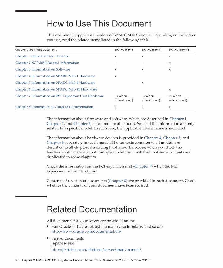
How to Use This DocumentThis document supports all models of SPARC M10 Systems. Depending on the serveryou use, read the related items listed in the following table.
The information about firmware and software, which are described in Chapter 1,Chapter 2, and Chapter 3, is common to all models. Some of the information are onlyrelated to a specific model. In such case, the applicable model name is indicated.
The information about hardware devices is provided in Chapter 4, Chapter 5, andChapter 6 separately for each model. The contents common to all models aredescribed in all chapters describing hardware. Therefore, when you check thehardware information about multiple models, you will find that some contents areduplicated in some chapters.
Check the information on the PCI expansion unit (Chapter 7) when the PCIexpansion unit is introduced.
Contents of revision of documents (Chapter 8) are provided in each document. Checkwhether the contents of your document have been revised.
Related DocumentationAll documents for your server are provided online.■ Sun Oracle software-related manuals (Oracle Solaris, and so on)http://www.oracle.com/documentation/
■ Fujitsu documentsJapanese site
http://jp.fujitsu.com/platform/server/sparc/manual/
Fujitsu M10/SPARC M10 Systems Product Notes for XCP Version 2050 ・ October 2013viii
Note - This document is given priority over the information in the SPARC M10 Systems-related documents.
SPARC M10 Systems related documentation (*1)
SPARC M10 Systems Getting Started Guide (*2)
SPARC M10 Systems Quick Guide
SPARC M10 Systems Important Legal and Safety Information (*2)
Software License Conditions for SPARC M10 Systems
SPARC M10 Systems Safety and Compliance Guide
SPARC M10 Systems Security Guide
SPARC M10 Systems/SPARC Enterprise/PRIMEQUEST Common Installation Planning Manual
SPARC M10 Systems Installation Guide
SPARC M10-1 Service Manual
SPARC M10-4/M10-4S Service Manual
PCI Expansion Unit for SPARC M10 Systems Service Manual
SPARC M10 Systems System Operation and Administration Guide
SPARC M10 Systems Domain Configuration Guide
SPARC M10 Systems XSCF Reference Manual
SPARC M10 Systems Product Notes
SPARC M10 Systems Glossary
*1: The listed manuals are subject to change without notice.
*2: The printed manual comes with the product.
Note - Enhanced Support Facility (ESF) and Remote Customer Support System (REMCS) aresupported only for SPARC M10 systems sold within Japan by Fujitsu.
Global site
http://www.fujitsu.com/global/services/computing/server/sparc/downloads/manual/
The following table lists the documents related to the SPARC M10 Systems.Read the related documents carefully when you use this product.
Documents provided on the DVD-ROM "SPARCEnterprise Software DVD
Remote maintenance service■ Enhanced Support Facility User's Guide for REMCS (J2X1-7753-EN)
Preface ix
Note - XSCF Control Package (XCP): XCP is a packaged control program of the hardwarethat configures SPARC M10 Systems. An XCP file includes the XSCF firmware, OpenBootPROM firmware, Power-On Self Test firmware, and Hypervisor firmware.
Note - This information is applicable to SPARC M10 systems sold within Japan by Fujitsu.
Information on firmware
This is information for customers of Fujitsu.
Obtain the firmware for your server from the following sources.■ Japanese siteThe customers who subscribed SupportDesk can obtain the firmware from theSupportDesk-Web.
■ Global siteFor how to obtain the latest files of the firmware, contact your sales representatives.
The following files are provided.■ Firmware program file (XSCF Control Package (XCP) file)■ XSCF extended MIB (XSCF-SP-MIB) definition file
Disposal and Recycling
For product disposal and recycling (paid service), contact your sales representatives.
Documentation FeedbackIf you have any comments or requests regarding this document, please take amoment to share it with us by indicating the manual code, manual title, and page,and stating your points specifically through the following websites:■ Japanese sitehttp://jp.fujitsu.com/platform/server/sparc/manual/
■ Global sitehttp://www.fujitsu.com/global/services/computing/server/sparc/downloads/manual/
Fujitsu M10/SPARC M10 Systems Product Notes for XCP Version 2050 ・ October 2013x
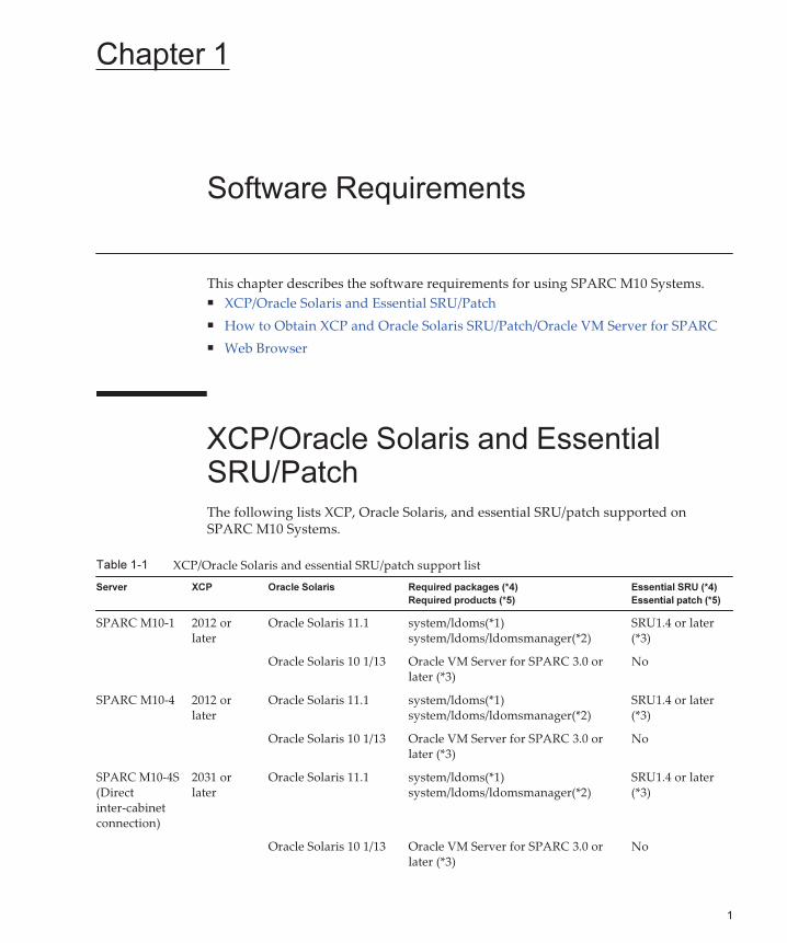
Table 1-1 XCP/Oracle Solaris and essential SRU/patch support list
Server XCP Oracle Solaris Required packages (*4)
Required products (*5)
Essential SRU (*4)
Essential patch (*5)
SPARC M10-1 2012 orlater
Oracle Solaris 11.1 system/ldoms(*1)system/ldoms/ldomsmanager(*2)
SRU1.4 or later(*3)
Oracle Solaris 10 1/13 Oracle VM Server for SPARC 3.0 orlater (*3)
No
SPARC M10-4 2012 orlater
Oracle Solaris 11.1 system/ldoms(*1)system/ldoms/ldomsmanager(*2)
SRU1.4 or later(*3)
Oracle Solaris 10 1/13 Oracle VM Server for SPARC 3.0 orlater (*3)
No
SPARC M10-4S(Directinter-cabinetconnection)
2031 orlater
Oracle Solaris 11.1 system/ldoms(*1)system/ldoms/ldomsmanager(*2)
SRU1.4 or later(*3)
Oracle Solaris 10 1/13 Oracle VM Server for SPARC 3.0 orlater (*3)
No
Chapter 1
Software Requirements
This chapter describes the software requirements for using SPARC M10 Systems.■ XCP/Oracle Solaris and Essential SRU/Patch
■ How to Obtain XCP and Oracle Solaris SRU/Patch/Oracle VM Server for SPARC
■ Web Browser
XCP/Oracle Solaris and EssentialSRU/PatchThe following lists XCP, Oracle Solaris, and essential SRU/patch supported onSPARC M10 Systems.
1
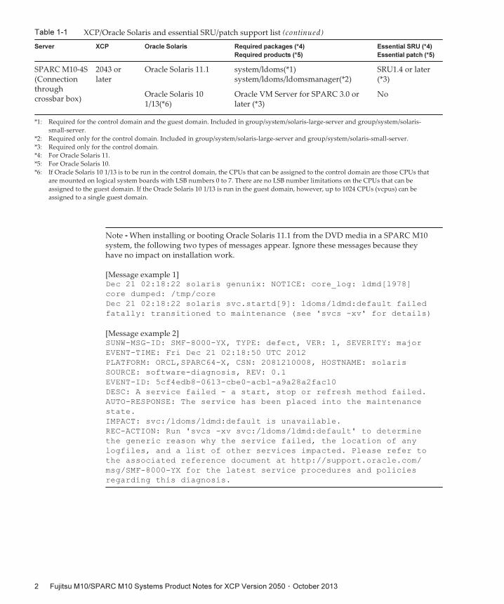
Table 1-1 XCP/Oracle Solaris and essential SRU/patch support list (continued)
Server XCP Oracle Solaris Required packages (*4)
Required products (*5)
Essential SRU (*4)
Essential patch (*5)
SPARC M10-4S(Connectionthroughcrossbar box)
2043 orlater
Oracle Solaris 11.1 system/ldoms(*1)system/ldoms/ldomsmanager(*2)
SRU1.4 or later(*3)
Oracle Solaris 101/13(*6)
Oracle VM Server for SPARC 3.0 orlater (*3)
No
*1: Required for the control domain and the guest domain. Included in group/system/solaris-large-server and group/system/solaris-
small-server.
*2: Required only for the control domain. Included in group/system/solaris-large-server and group/system/solaris-small-server.
*3: Required only for the control domain.
*4: For Oracle Solaris 11.
*5: For Oracle Solaris 10.
*6: If Oracle Solaris 10 1/13 is to be run in the control domain, the CPUs that can be assigned to the control domain are those CPUs that
are mounted on logical system boards with LSB numbers 0 to 7. There are no LSB number limitations on the CPUs that can be
assigned to the guest domain. If the Oracle Solaris 10 1/13 is run in the guest domain, however, up to 1024 CPUs (vcpus) can be
assigned to a single guest domain.
Note - When installing or booting Oracle Solaris 11.1 from the DVD media in a SPARC M10system, the following two types of messages appear. Ignore these messages because theyhave no impact on installation work.
[Message example 1]Dec 21 02:18:22 solaris genunix: NOTICE: core_log: ldmd[1978]
core dumped: /tmp/core
Dec 21 02:18:22 solaris svc.startd[9]: ldoms/ldmd:default failed
fatally: transitioned to maintenance (see 'svcs -xv' for details)
[Message example 2]SUNW-MSG-ID: SMF-8000-YX, TYPE: defect, VER: 1, SEVERITY: major
EVENT-TIME: Fri Dec 21 02:18:50 UTC 2012
PLATFORM: ORCL,SPARC64-X, CSN: 2081210008, HOSTNAME: solaris
SOURCE: software-diagnosis, REV: 0.1
EVENT-ID: 5cf4edb8-0613-cbe0-acb1-a9a28a2fac10
DESC: A service failed - a start, stop or refresh method failed.
AUTO-RESPONSE: The service has been placed into the maintenance
state.
IMPACT: svc:/ldoms/ldmd:default is unavailable.
REC-ACTION: Run 'svcs -xv svc:/ldoms/ldmd:default' to determine
the generic reason why the service failed, the location of any
logfiles, and a list of other services impacted. Please refer to
the associated reference document at http://support.oracle.com/
msg/SMF-8000-YX for the latest service procedures and policies
regarding this diagnosis.
Fujitsu M10/SPARC M10 Systems Product Notes for XCP Version 2050 ・ October 20132
Note - When Oracle Solaris 11.1 is installed in SPARC M10 Systems, the following messageappears at the start of Oracle Solaris.
[Example of message]WARNING: failed to instantiate provider ldmd for process 753
WARNING: failed to instantiate provider ldmd for process 753
Sep 24 06:15:59 svc.startd[11]: svc:/ldoms/ldmd:default: Method
"/opt/SUNWldm/bin/ldmd_start" failed with exit status 95.
Sep 24 06:15:59 svc.startd[11]: ldoms/ldmd:default failed fatally:
transitioned to maintenance (see 'svcs -xv' for details)
After Oracle Solaris 11.1 is installed, apply SRU1.4 or later.Then, the Oracle VM Server for SPARC package is updated to the version supporting SPARCM10 Systems, and such message will no longer be output.
Table 1-2 Version of web browser of which operation has been confirmed
Web browser Version
Microsoft Internet Explorer 8.0 and 9.0
Firefox 10.0 or later
For other information about Oracle Solaris, see "Problems with Oracle Solaris andWorkarounds."
How to Obtain XCP and Oracle SolarisSRU/Patch/Oracle VM Server forSPARCThe customers who subscribed SupportDesk can obtain the latest XCP firmware andOracle Solaris SRU/patch/Oracle VM Server for SPARC from the SupportDesk-Web.
Web BrowserTable 1-2 lists the web browsers on which the XSCF Web operation is confirmed. Forother information about XSCF Web, see "Notes and restrictions on XSCF Web."
Chapter 1 Software Requirements 3

Fujitsu M10/SPARC M10 Systems Product Notes for XCP Version 2050 ・ October 20134
Chapter 2
XCP 2050-Related Information
This chapter provides XCP 2050-related information.■ Latest Information on XCP 2050
■ Direct I/O Function for the PCI Expansion Unit
■ Notes and Restrictions
■ XCP 2050 Problems and Workarounds
Latest Information on XCP 2050This section describes newly added functions for XCP 2050.■ [SPARC M10-4S]The direct I/O function is now supported for the PCI expansionunit. For details, see "Direct I/O Function for the PCI Expansion Unit."
■ Data input/output using SSH, HTTP, HTTPS, and FTP is now possible with thecommands below.getflashimage(8), dumpconfig(8), restoreconfig(8), setremotepwrmgmt(8),getremotepwrmgmt(8), addcodactivation(8), dumpcodactivation(8),restorecodactivation(8), snapshot(8)
■ Capacity on Demand (CoD) logs can now be sent by mail with theshowcodactivationhistory(8) command.
■ The commands below are now supported, which enable the Auto Service Request(ASR) function.setservicetag(8), showservicetag(8)
For details on the ASR function, see Oracle Auto Service Request Installation andOperation Guide for the version used.
■ Updating the firmware of XCP 2050, at which time the master and standby ofXSCF are switched over, will now automatically change them back to the statusbefore the switchover. For details, see "Notes on firmware update."
5
Direct I/O Function for the PCIExpansion UnitFor XCP 2044 or later of SPARC M10-1/M10-4 and for XCP 2050 or later of SPARCM10-4S, the direct I/O function of Oracle VM Server for SPARC is supported for thePCI expansion unit. This makes it possible to assign an I/O domain for each slot ofthe PCI expansion unit. For details on the direct I/O function of Oracle VM Server forSPARC, see Oracle VM Server for SPARC Administration Guide for the version used.If the PCI expansion unit is connected to SPARC M10-4, make the setting belowbefore using the direct I/O function. For SPARC M10-1, the setting below need not bemade. The direct I/O function can be used simply by connecting the PCI expansionunit to SPARC M10-1.
Setting/displaying the direct I/O function
To set the direct I/O function for the PCI expansion unit, use the setpciboxdio(8)command of the XSCF firmware. To confirm the present settings, use theshowpciboxdio(8) command.For details on the setpciboxdio(8) and showpciboxdio(8) commands, see SPARC M10Systems XSCF Reference Manual or the manual page for each command.
Fujitsu M10/SPARC M10 Systems Product Notes for XCP Version 2050 ・ October 20136
Notes and RestrictionsThis section describes notes and restrictions that are known as of this release.
Notes on OpenBoot PROM
■ If you execute the sendbreak(8) command after the OpenBoot PROM bannerappears on the domain console but before OpenBoot PROM startup is completed,the following error message is output. In this case, the boot command becomesunable to be executed.FATAL: OpenBoot initialization sequence prematurely
terminated.
In this case, set the OpenBoot PROM environment variable auto-boot? to false atthe ok prompt, and execute the reset-all command. When OpenBoot PROM isrestarted, set auto-boot? to true, and execute the boot command.
■ When you use the XSCF firmware setpparparam(8) command to set an OpenBootPROM environment variable, such as nvramrc, the maximum number ofcharacters that can be set is 254.If you want to set a string of 255 or more characters in an OpenBoot PROMenvironment variable, such as nvramrc, do so in the OpenBoot PROM or OracleSolaris environment. Note that, however, the maximum number of characters is1024.
■ The OpenBoot PROM device aliases disk and net are not created for Oracle VMServer for SPARC disks and logical domains to which no network is assigned. Toexecute disk boot or network boot by specifying the device alias disk or net, set thedevice aliases disk and net by using the OpenBoot PROM nvalias command.
Notes on maintenance for CPU memory unit andmotherboard unit
The setting information of the CPU core activation and the CPU core activation keymay be deleted when the CPU Memory Unit lower (CMUL) or the Mother BoardUnit (MBU) is replaced. To restore the setting information of CPU core activation andthe CPU core activation key, it is necessary to save the setting information of the CPUcore activation and CPU core activation key beforehand, using the dumpconfig(8)command and restore them with the restoreconfig(8) command.
Notes on CPU core activation
■ If the XSCF setting information is initialized by executing the restoredefaults(8)command in XCP 2032 or earlier, the information of the CPU core activation key is
Chapter 2 XCP 2050-Related Information 7
also initialized.When executing the restoredefaults(8) command, save the CPU core activation keyin advance before restoring it or register the key again.
■ If you execute the restoredefaults -c xscf command on XCP 2041 or later, theinformation of the CPU core activation key is deleted not only from the XSCF unitbut also from the backup information in the XSCF. On the other hand, even if youexecute the restoredefaults -c factory command, the information of the CPU coreactivation key is not deleted.To initialize all settings to factory defaults including the information of the CPUcore activation key, use the -c factory -r activation option.
For the information of changes the restoredefaults(8) commands, see Contents ofRevision of SPARC M10 Systems XSCF Reference Manual.
■ XSCF setting information saved by the dumpconfig(8) command contains CPUcore activation information and CPU core activation keys.You can use the restoreconfig(8) command to restore CPU core activationinformation and CPU core activation keys saved by the dumpconfig(8) command.
Therefore, if you configure CPU core activation or install a CPU core activationkey when configuring some settings for the XSCF, such as configuring an XSCFnetwork or physical partition (PPAR), it is recommended to save the CPU coreactivation information and CPU core activation key by using the dumpconfig(8)command. To save and restore only CPU core activation keys, execute thedumpcodactivation(8) and restorecodactivation(8) commands, respectively. Notethat, however, these commands cannot save and restore CPU core activationinformation. Use the showcod(8) and setcod(8) commands to reconfigure CPUcore activation.
Notes and restrictions on XSCF Web
Notes
(1) Common to browsers
■ When you import XCP or update firmware by using XSCF Web, "Session isinvalid" may appear on the web browser.
■ If the timeout of the XSCF shell is short when you import XCP by using XSCFWeb, XCP importing fails. Set the timeout of the XSCF shell to 30 minutes orlonger.Select the [menu] tab and select [XSCF] - [Settings] - [Autologout] menu. Then,enter a value of 30 minutes or greater in [Time-out value].
(2) Internet Explorer
There are no notes known at present.
(3) Firefox
■ If you use XSCF Web in a Firefox environment, the browser may prompt you tosave the login ID and password when you log in to the XSCF. In this case, do notsave the login ID and password. If you save the login ID and password, the saved
Fujitsu M10/SPARC M10 Systems Product Notes for XCP Version 2050 ・ October 20138
Note - Remote Customer Support System (REMCS) is supported only for SPARC M10systems sold within Japan by Fujitsu.
data may be displayed on LDAP, SMTP, and REMCS web pages.
Configure either of the following settings to disable the login ID/password savefunction of the browser:
■ Disable the login ID/password save function across the entire browserSelect[Tools] - [Options] - [Security] tab, and uncheck [Remember passwords forsites] in [Passwords].
■ Specify an exception for ID and password savingSelect [Tools] - [Options] -[Security] tab, and check [Remember passwords for sites] in [Passwords]. Then,click the [Never Remember Password for This Site] button in the dialog box forID and password saving that appears when you log in to the XSCF. Thisregisters the address of the XSCF in the [Exceptions] list for ID and passwordsaving, and the dialog box for ID and password saving does not appear atsubsequent logins to the XSCF.
Restrictions
(1) Common to browsers
There are no restrictions known at present.
(2) Internet Explorer
If you use Internet Explorer 8 in a Windows 7 environment, built-in Administratoraccounts cannot be used.
(3) Firefox
There are no restrictions known at present.
Notes on firmware update
■ [SPARC M10-1]In the configuration including a PCI Expansion unit being connected, the logicaldomain configuration of PPAR (physical partition) will be restored to factory-default at the next boot when updating the firmware from XCP 2043 or earlier toXCP 2044 or later. Also the OpenBoot PROM environment variables are initialized.
■ [SPARC M10-4S]If you update the firmware by executing the flashupdate(8) command or usingXSCF Web, the time for the processing depends on the number of SPARC M10-4Scabinets or crossbar boxes that configure the system.
■ The relationship of the master XSCF and the standby XSCF after the update of theXSCF firmware depends on the version of the updated XCP.The following table shows the relationship between the master XSCF and thestandby XSCF as well as the operation examples of firmware update, for each XCPversion.
Chapter 2 XCP 2050-Related Information 9
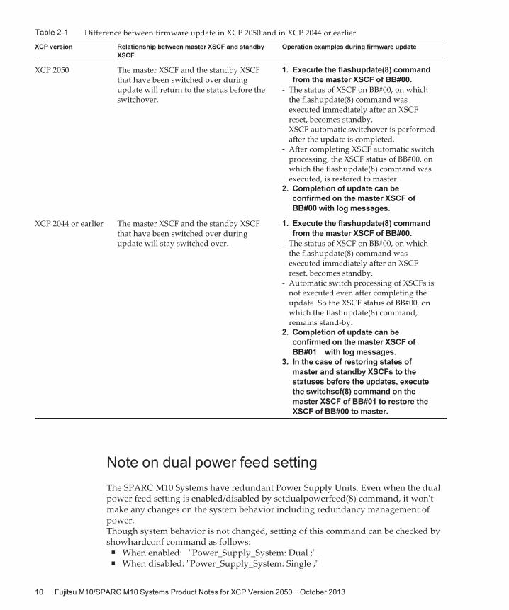
Table 2-1 Difference between firmware update in XCP 2050 and in XCP 2044 or earlier
XCP version Relationship between master XSCF and standby
XSCF
Operation examples during firmware update
XCP 2050 The master XSCF and the standby XSCFthat have been switched over duringupdate will return to the status before theswitchover.
1. Execute the flashupdate(8) command
from the master XSCF of BB#00.
- The status of XSCF on BB#00, on whichthe flashupdate(8) command wasexecuted immediately after an XSCFreset, becomes standby.
- XSCF automatic switchover is performedafter the update is completed.
- After completing XSCF automatic switchprocessing, the XSCF status of BB#00, onwhich the flashupdate(8) command wasexecuted, is restored to master.
2. Completion of update can be
confirmed on the master XSCF of
BB#00 with log messages.
XCP 2044 or earlier The master XSCF and the standby XSCFthat have been switched over duringupdate will stay switched over.
1. Execute the flashupdate(8) command
from the master XSCF of BB#00.
- The status of XSCF on BB#00, on whichthe flashupdate(8) command wasexecuted immediately after an XSCFreset, becomes standby.
- Automatic switch processing of XSCFs isnot executed even after completing theupdate. So the XSCF status of BB#00, onwhich the flashupdate(8) command,remains stand-by.
2. Completion of update can be
confirmed on the master XSCF of
BB#01 with log messages.
3. In the case of restoring states of
master and standby XSCFs to the
statuses before the updates, execute
the switchscf(8) command on the
master XSCF of BB#01 to restore the
XSCF of BB#00 to master.
Note on dual power feed setting
The SPARC M10 Systems have redundant Power Supply Units. Even when the dualpower feed setting is enabled/disabled by setdualpowerfeed(8) command, it won'tmake any changes on the system behavior including redundancy management ofpower.Though system behavior is not changed, setting of this command can be checked byshowhardconf command as follows:
■ When enabled: "Power_Supply_System: Dual ;"■ When disabled: "Power_Supply_System: Single ;"
Fujitsu M10/SPARC M10 Systems Product Notes for XCP Version 2050 ・ October 201310
This function can be used as "memo" for administrator to distinguish whether acustomer's facility is configured as dual power feed or not.
Other notes and restrictions
Notes
■ [SPARC M10-1/M10-4/M10-4S]The maximum number of users who can concurrently connect to the XSCF viaTelnet and SSH is as follows:
■ M10-1: 20 users
■ M10-4: 40 users
■ M10-4S (without crossbar box): 40 users
■ M10-4S (with crossbar box): 70 users
If the maximum allowable number of users is exceeded, access is denied.
■ If the following error log is registered with the XSCF, do not power on thephysical partition (PPAR) but replace the PSU backplane:FRU : /PSUBP
Msg: SCF Diagnosis error on System backup memory
■ XSCF-LAN is compliant with auto-negotiation. If you connect XSCF-LAN to anetwork device that is fixed to full-duplex mode, the XSCF-LAN communicates inhalf-duplex mode according to the IEEE 802.3 protocol. This may slow down thespeed of network communication or cause communication error. Be sure to setauto-negotiation for network devices to which you connect XSCF-LAN.
■ Settings made by the setdualpowerfeed(8) command are immediately applied.Therefore, the XSCF does not need to be reset.
■ The ioxadm poweroff(8) command can be specified with the -f option only for apower supply unit.
■ Configuring a memory mirror setting by using the setupfru(8) command shouldbe done when the physical partition (PPAR) to which the target system board(PSB) belongs is powered off.
■ To display a man page, set TERM=vt100 for the terminal software.
■ When configuring a physical partition (PPAR), do not set a BB-ID that does notexist in the system as the PPAR-ID.For example, if BB-IDs 00 and 01 exist in the system, you can set 00 or 01 as thePPAR-ID. If you set 02 as the PPAR-ID, the PPAR with PPAR-ID 02 becomesunable to start.
■ Among the information displayed by executing the showhardconf(8) command,the PCI Express (PCIe) card information of the guest domain will be reflected afterOracle Solaris of the corresponding guest domain has started.
■ As of XCP 2032, the default value for the power save operation set by thesetpparmode(8) command is changed from "enabled" to "disabled."
Chapter 2 XCP 2050-Related Information 11
■ When you execute the testsb(8) or diagxbu(8) command, a PPAR-ID of "PPAR#30"that does not exist may appear in an error log suspected area. This indicates thatan error was detected on the system board (PSB) while diagnosing. The outputPPAR-ID does not have any meaning.
■ We recommend to connect the control domain console via the XSCF-LAN port.When a large amount of data is output by connecting to the control domainconsole via a serial port, the data may not be displayed properly.
■ [SPARC M10-4S]The time taken for processing a command that displays the system configurationor status (such as showhardconf(8) command, showboards(8) command, andshowpparstatus(8) command) depends on the number of SPARC M10-4S cabinetsor crossbar boxes that configure the system.
■ [SPARC M10-4S] For a system configured with multiple cabinets, cabinet BB#01 orXBBOX#81 may become the master XSCF first.
■ [SPARC M10-4S] Depending on the system configuration, it may take time toreboot.
■ If you add a SPARC M10-4S to the SPARC M10-4S on which XCP 2032 is installed,update to the latest firmware in advance.
■ When you execute the setsnmpvacm(8) command specifying createview as theoperand, you cannot set an access restriction using the OID mask of MIB. Whenyou execute the setsnmpvacm(8) command specifying createview as the operand,do not use the OID mask of MIB.
■ Do not register the same node with multiple power supply interlocking groups. Ifpower supply interlocking is performed by registering a single node with multiplepower supply interlocking groups, the operation may not be as intended.With the setremotepwrmgmt(8) command, you cannot confirm whether a singlenode is registered with multiple power supply interlocking groups. When creatingor modifying a power supply interlocking group management information file,take care not to cause overlaps.
■ Do not register an I/O node with multiple power control groups. If the same I/Onode is set with multiple power supply interlocking groups, and both of theconditions below are met, the I/O node is turned on and off alternately.■ setremotepwrmgmt -c enable is executed, and the power supply interlockingfunction is enabled.
■ A power control group where one or more host nodes are on exist, so does apower control group where all host nodes are off.
If you accidentally register an I/O node with multiple power control groups, usesetremotepwrmgmt -c disable to disable power supply interlocking first and thenuse clearremotepwrmgmt to delete the power control group setting. Afterdeletion, create a power supply interlocking group management information fileso that the I/O node is not registered with multiple groups, and then usesetremotepwrmgmt -c config to register it again.
■ When takeover IP address is set, the source IP address of the UDP packets of theSMTP Trap of SNMPv1, differs from the Agent Address. The source IP address ofUDP packets contains the IP address(physical address) that are allotted to eachXSCF-LAN.The Agent Address contains the takeover IP address(virtual IP address).
Fujitsu M10/SPARC M10 Systems Product Notes for XCP Version 2050 ・ October 201312
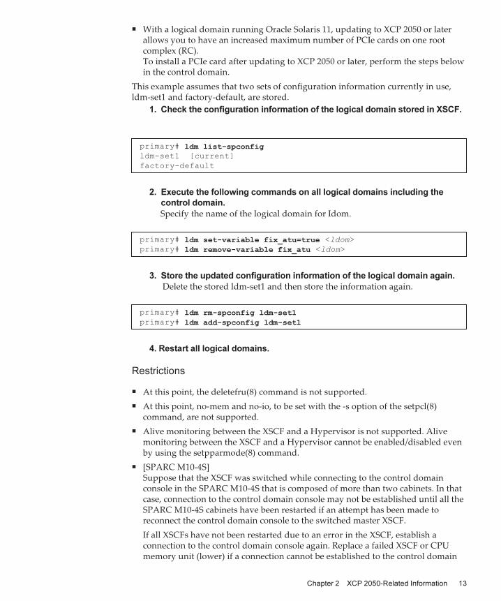
primary# ldm list-spconfigldm-set1 [current]
factory-default
primary# ldm set-variable fix_atu=true <ldom>
primary# ldm remove-variable fix_atu <ldom>
primary# ldm rm-spconfig ldm-set1primary# ldm add-spconfig ldm-set1
■ With a logical domain running Oracle Solaris 11, updating to XCP 2050 or laterallows you to have an increased maximum number of PCIe cards on one rootcomplex (RC).To install a PCIe card after updating to XCP 2050 or later, perform the steps belowin the control domain.
This example assumes that two sets of configuration information currently in use,ldm-set1 and factory-default, are stored.
1. Check the configuration information of the logical domain stored in XSCF.
2. Execute the following commands on all logical domains including the
control domain.
Specify the name of the logical domain for Idom.
3. Store the updated configuration information of the logical domain again.
Delete the stored ldm-set1 and then store the information again.
4. Restart all logical domains.
Restrictions
■ At this point, the deletefru(8) command is not supported.
■ At this point, no-mem and no-io, to be set with the -s option of the setpcl(8)command, are not supported.
■ Alive monitoring between the XSCF and a Hypervisor is not supported. Alivemonitoring between the XSCF and a Hypervisor cannot be enabled/disabled evenby using the setpparmode(8) command.
■ [SPARC M10-4S]Suppose that the XSCF was switched while connecting to the control domainconsole in the SPARC M10-4S that is composed of more than two cabinets. In thatcase, connection to the control domain console may not be established until all theSPARC M10-4S cabinets have been restarted if an attempt has been made toreconnect the control domain console to the switched master XSCF.
If all XSCFs have not been restarted due to an error in the XSCF, establish aconnection to the control domain console again. Replace a failed XSCF or CPUmemory unit (lower) if a connection cannot be established to the control domain
Chapter 2 XCP 2050-Related Information 13
console.
■ [SPARC M10-4S]The poweroff(8) and reset(8) commands may not be executed normally if all XSCFhave not been restarted due to an error in a XSCF in the SPARC M10-4S that iscomposed of more than two cabinets.
To disconnect the power of a physical partition (PPAR), login to the controldomain of the PPAR and execute the shutdown(1M) command on Oracle Solaris.Then, disconnect the power of the PPAR using the poweroff -f command on theXSCF firmware. The reset(8) command cannot be used in this state.
■ The -c wait option, which is used to set the air-conditioning wait time for thesetpowerupdelay(8) command, is not supported at present.
■ Ask your sales representatives regarding the support information of the dynamicreconfiguration (DR) of the system board (PSB).The command options related to the dynamic reconfiguration are as follows.
■ -c configure of the addboard(8) command
■ -c disconnect of the deleteboard(8) command (when the PPAR is powered on)
■ -c unassign of the deleteboard(8) command (when the PPAR is powered on)
■ The -p option of the diagxbu(8) command is not supported at present.
■ Replacement of a crossbar box using the replacefru(8) command is not supportedat present. For how to replace a crossbar box, see "Restrictions on replacingcrossbar box" in "Chapter 6 Information on SPARC M10-4S Hardware."
■ Addition of a crossbar box using the addfru(8) command is not supported atpresent. For how to add a crossbar box, see "Restrictions on adding expansion rack2" in "Chapter 6 Information on SPARC M10-4S Hardware."
■ [SPARC M10-4S]At this point, the direct I/O function for the PCI expansion unit isnot supported.
■ [SPARC M10-4S]If you power on all physical partitions (PPAR) in a system that has more than onePPARs with the poweron(8) command, the startup time taken when specifyingpower-on of PPAR is longer than the time taken for batch power-on by specifying-a.
■ [SPARC M10-4/M10-4S]As for the ioreconfigure that can be specified by -m function of the setpparmode(8) command, leave it as the default, false, and disable the I/O bus reconfigurationfunction. If you enable the I/O bus reconfiguration function by specifying true tothe ioreconfigure, it may be necessary to reinstall Oracle Solaris.
■ [SPARC M10-4S]If showhardconf -M is executed, it may not be possible to display one screen at atime if both of the conditions below are met. Do not execute showhardconf -M.
■ System configured with 2BB or greater
■ One or more SPARC M10-4Ss are subject to an XSCF reset with the rebootxscf(8) command, so they cannot communicate.
Fujitsu M10/SPARC M10 Systems Product Notes for XCP Version 2050 ・ October 201314
XCP 2050 Problems and WorkaroundsSee "Problems that might occur with XCP 2050 and workarounds" for information onproblems that can occur with XCP 2050. See "Problems resolved in XCP 2050" forinformation on problems resolved in XCP 2050.
Chapter 2 XCP 2050-Related Information 15

Fujitsu M10/SPARC M10 Systems Product Notes for XCP Version 2050 ・ October 201316
Chapter 3
Information on Software
This chapter describes special instructions and problems concerning the SPARC M10Systems software.■ Notes and Restrictions
■ Problems with XCP and Workarounds
■ Problems with Oracle Solaris and Workarounds
Notes and Restrictions
Notes on Oracle VM Server for SPARC
■ If you operate a guest domain with the reset(8) command of the XSCF firmwareafter reconfiguring a logical domain with Oracle VM Server for SPARC and beforeexecuting the ldm add-spconfig command, another guest domain may be reset. Orthe specified guest domain will not be reset. Save a configuration of the logicaldomain with the ldm add-spconfig command. If you reset the guest domainbefore saving it, execute the ldm stop command from the control domain, notfrom XSCF.
■ If you specify a logical domain configuration for next time you start, use the ldmset-config command in place of ldm add-spconfig -r.If you use the ldm add-spconfig -r command to specify a logical domainconfiguration for next time you start, and operate a guest domain with the reset(8)command of the XSCF firmware, another guest domain may be reset.
■ If you execute the ldm migrate-domain command with Oracle VM Server forSPARC, the following problems will occur in XSCF:■ If you execute the showdomainstatus(8) command, the status of the migratedguest domain shows "Unknown".
■ When the physical partition (PPAR) is powered off with the poweroff(8)command, all the guest domains may not be properly shut down.
17
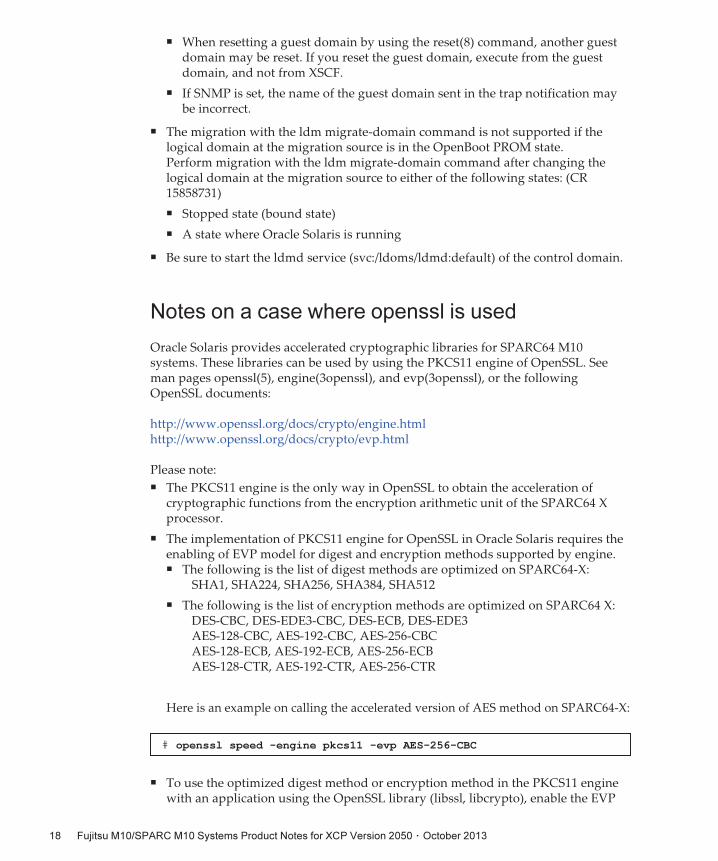
# openssl speed -engine pkcs11 -evp AES-256-CBC
■ When resetting a guest domain by using the reset(8) command, another guestdomain may be reset. If you reset the guest domain, execute from the guestdomain, and not from XSCF.
■ If SNMP is set, the name of the guest domain sent in the trap notification maybe incorrect.
■ The migration with the ldm migrate-domain command is not supported if thelogical domain at the migration source is in the OpenBoot PROM state.Perform migration with the ldm migrate-domain command after changing thelogical domain at the migration source to either of the following states: (CR15858731)
■ Stopped state (bound state)
■ A state where Oracle Solaris is running
■ Be sure to start the ldmd service (svc:/ldoms/ldmd:default) of the control domain.
Notes on a case where openssl is used
Oracle Solaris provides accelerated cryptographic libraries for SPARC64 M10systems. These libraries can be used by using the PKCS11 engine of OpenSSL. Seeman pages openssl(5), engine(3openssl), and evp(3openssl), or the followingOpenSSL documents:
http://www.openssl.org/docs/crypto/engine.htmlhttp://www.openssl.org/docs/crypto/evp.html
Please note:■ The PKCS11 engine is the only way in OpenSSL to obtain the acceleration ofcryptographic functions from the encryption arithmetic unit of the SPARC64 Xprocessor.
■ The implementation of PKCS11 engine for OpenSSL in Oracle Solaris requires theenabling of EVP model for digest and encryption methods supported by engine.■ The following is the list of digest methods are optimized on SPARC64-X:
SHA1, SHA224, SHA256, SHA384, SHA512
■ The following is the list of encryption methods are optimized on SPARC64 X:DES-CBC, DES-EDE3-CBC, DES-ECB, DES-EDE3AES-128-CBC, AES-192-CBC, AES-256-CBCAES-128-ECB, AES-192-ECB, AES-256-ECBAES-128-CTR, AES-192-CTR, AES-256-CTR
Here is an example on calling the accelerated version of AES method on SPARC64-X:
■ To use the optimized digest method or encryption method in the PKCS11 enginewith an application using the OpenSSL library (libssl, libcrypto), enable the EVP
Fujitsu M10/SPARC M10 Systems Product Notes for XCP Version 2050 ・ October 201318

Note - Enhanced Support Facility (ESF) and Remote Customer Support System (REMCS) aresupported only for SPARC M10 systems sold within Japan by Fujitsu.
interface explained in evp(3openssl).
Notes on remote maintenance service
This section describes notes when using the remote maintenance service. SeeEnhanced Support Facility User's Guide for REMCS for how to set and use REMCS.
Before setting the remote maintenance service
To use the remote maintenance service with SPARC M10 Systems, you must performsettings for the REMCS agent function by using XSCF Web. In addition, the REMCSagent uses timezone information of XSCF. Perform the following settings in advancewith the XSCF shell:
■ Setting necessary for using the XSCF Web, such as enabling the HTTPS setting■ Setting the timezone for XSCF
After completing the above settings, perform settings for the REMCS agent functionby using the XSCF Web.See SPARC M10 Systems System Operation and Administration Guide for details of theXSCF Web settings and timezone settings.
Timezone for the REMCS agent function
The REMCS agent uses the timezone currently set for the system. For this reason,when you change the system timezone with XSCF, set the periodical connectionschedule again to update the information of REMCS center.
Problems with XCP and WorkaroundsThis section describes problems with XCP and workarounds for each version.
Problems that might occur with XCP 2050 andworkarounds
The following table shows problems that might occur with XCP 2050 and workaroundsfor them.
Chapter 3 Information on Software 19
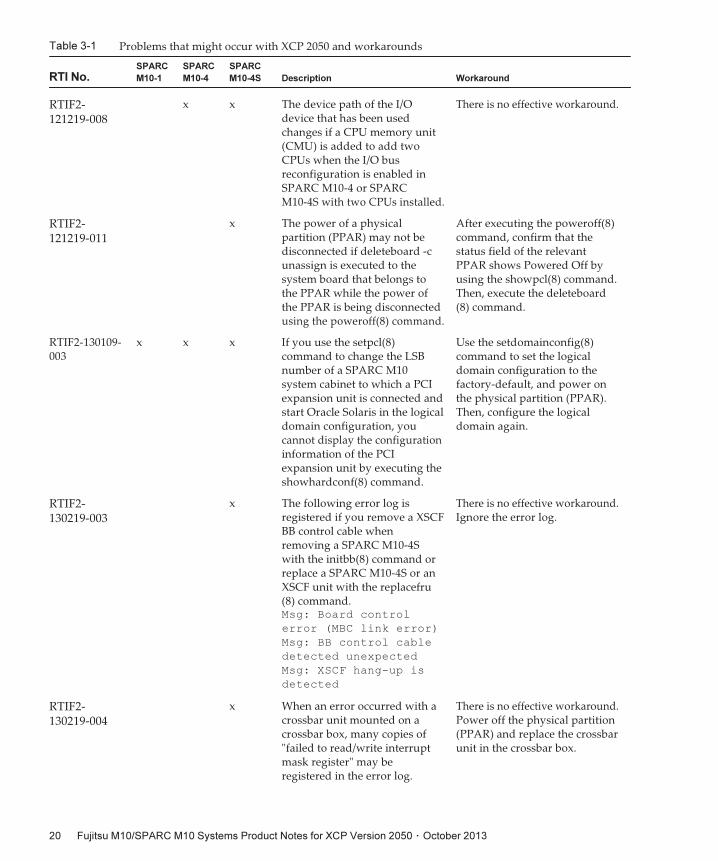
Table 3-1 Problems that might occur with XCP 2050 and workarounds
RTI No.
SPARC
M10-1
SPARC
M10-4
SPARC
M10-4S Description Workaround
RTIF2-
121219-008
x x The device path of the I/Odevice that has been usedchanges if a CPU memory unit(CMU) is added to add twoCPUs when the I/O busreconfiguration is enabled inSPARC M10-4 or SPARCM10-4S with two CPUs installed.
There is no effective workaround.
RTIF2-
121219-011
x The power of a physicalpartition (PPAR) may not bedisconnected if deleteboard -cunassign is executed to thesystem board that belongs tothe PPAR while the power ofthe PPAR is being disconnectedusing the poweroff(8) command.
After executing the poweroff(8)command, confirm that thestatus field of the relevantPPAR shows Powered Off byusing the showpcl(8) command.Then, execute the deleteboard(8) command.
RTIF2-130109-003
x x x If you use the setpcl(8)command to change the LSBnumber of a SPARC M10system cabinet to which a PCIexpansion unit is connected andstart Oracle Solaris in the logicaldomain configuration, youcannot display the configurationinformation of the PCIexpansion unit by executing theshowhardconf(8) command.
Use the setdomainconfig(8)command to set the logicaldomain configuration to thefactory-default, and power onthe physical partition (PPAR).Then, configure the logicaldomain again.
RTIF2-
130219-003
x The following error log isregistered if you remove a XSCFBB control cable whenremoving a SPARC M10-4Swith the initbb(8) command orreplace a SPARC M10-4S or anXSCF unit with the replacefru(8) command.Msg: Board control
error (MBC link error)
Msg: BB control cable
detected unexpected
Msg: XSCF hang-up is
detected
There is no effective workaround.Ignore the error log.
RTIF2-
130219-004
x When an error occurred with acrossbar unit mounted on acrossbar box, many copies of"failed to read/write interruptmask register" may beregistered in the error log.
There is no effective workaround.Power off the physical partition(PPAR) and replace the crossbarunit in the crossbar box.
Fujitsu M10/SPARC M10 Systems Product Notes for XCP Version 2050 ・ October 201320
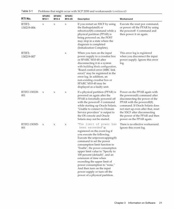
Table 3-1 Problems that might occur with XCP 2050 and workarounds (continued)
RTI No.
SPARC
M10-1
SPARC
M10-4
SPARC
M10-4S Description Workaround
RTIF2-
130219-006
x x x If you restart an XSCF by usingthe flashupdate(8) orrebootxscf(8) command while aphysical partition (PPAR) isbeing powered on, the POSTmay stop in a state where thediagnosis is completed(Initialization Complete).
Execute the reset por command,or power off the PPAR by usingthe poweroff -f command andthen power it on again.
RTIF2-
130219-007
x When you turn on the inputpower supply to a crossbar boxor SPARC M10-4S afterdisconnecting it in a systemwith building block configuration,"Board control error (MBC linkerror)" may be registered in theerror log. In addition, annon-existing crossbar box orSPARC M10-4S may bedisplayed as a faulty unit.
This error log is registeredwhen you disconnect the inputpower supply. Ignore this errorlog.
RTIF2-130228-001
x x x If a physical partition (PPAR) ispowered on again after thePPAR is forcefully powered offwith the poweroff -f commandwhile starting up Oracle Solaris,"Unable to connect to DomainService providers" is output tothe OS console and OracleSolaris may not be started.
Power on the PPAR again withthe poweron(8) command afterdisconnecting the power of thePPAR with the poweroff(8)command. If Oracle Solaris doesnot start up even after that, resetthe XSCF after disconnectingthe power of the PPAR and thenpower on the PPAR again.
RTIF2-130305-001
x x x "The limit of power has
been exceeded" isregistered on the event log ifyou execute the following.Execute the setpowercapping(8)command to set the powerconsumption limit function to"Enable", the power consumptionupper limit value to "Specify to100 percent (default)", and anextension of time whenexceeding the upper limit ofpower consumption to "none."And then turn on the inputpower supply or turn off thepower of a physical partition.
There is no effective workaround.Ignore this event log.
Chapter 3 Information on Software 21
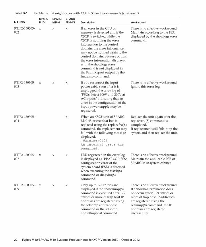
Table 3-1 Problems that might occur with XCP 2050 and workarounds (continued)
RTI No.
SPARC
M10-1
SPARC
M10-4
SPARC
M10-4S Description Workaround
RTIF2-130305-002
x x x If an error in the CPU ormemory is detected and if theXSCF is switched while theXSCF is notifying the errorinformation to the controldomain, the error informationmay not be notified again to thecontrol domain. Because of this,the error information displayedwith the showlogs errorcommand is not displayed inthe Fault Report output by thefmdump command.
There is no effective workaround.Maintain according to the FRUdisplayed by the showlogs errorcommand.
RTIF2-130305-003
x x x If you reconnect the inputpower cable soon after it isunplugged, the error log of"PSUs detect 100V and 200V atAC inputs" indicating that anerror in the configuration of theinput power supply may beregistered.
There is no effective workaround.Ignore this error log.
RTIF2-130305-004
x When an XSCF unit of SPARCM10-4S or crossbar box isreplaced using the replacefru(8)command, the replacement mayfail with the following messagedisplayed.[Warning:010]
An internal error has
occurred.
Replace the unit again after thereplacefru(8) command iscompleted.If replacement still fails, stop thesystem and then replace the unit.
RTIF2-130305-007
x x x FRU registered in the error logis displayed as "PPAR#30" if theconfiguration error of thesystem board (PSB) is detectedwhen executing the testsb(8)command or diagxbu(8)command.
There is no effective workaround.Maintain the applicable PSB ofSPARC M10 system cabinet.
RTIF2-130305-009
x x x Only up to 128 entries aredisplayed if the showsnmp(8)command is executed after 129entries or more of trap host IPaddresses are registered usingthe setsnmp addtraphostcommand or the setsnmpaddv3traphost command.
There is no effective workaround.If abnormal termination doesnot occur when 129 entries ormore of trap host IP addressesare registered using thesetsnmp(8) command, the IPaddresses are registeredsuccessfully.
Fujitsu M10/SPARC M10 Systems Product Notes for XCP Version 2050 ・ October 201322
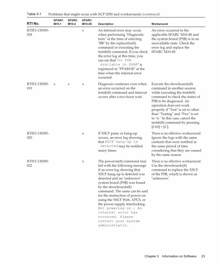
Table 3-1 Problems that might occur with XCP 2050 and workarounds (continued)
RTI No.
SPARC
M10-1
SPARC
M10-4
SPARC
M10-4S Description Workaround
RTIF2-130305-018
x An internal error may occurwhen performing "Diagnostictests" at the time of selecting"BB" by the replacefru(8)command or executing thetestsb(8) command. If you checkthe error log at this time, youcan see that "no PSB
available in PPAR" isregistered in "PPAR#30" at thetime when the internal erroroccurred.
An error occurred in theapplicable SPARC M10-4S andthe system board (PSB) is in anunavailable state. Check theerror log and replace theSPARC M10-4S.
RTIF2-130305-019
x x x Diagnosis continues even whenan error occurred on thetestsb(8) command and timeoutoccurs after a two-hour wait.
Execute the showboards(8)command in another sessionwhile executing the testsb(8)command to check the status ofPSB to be diagnosed. Anoperation does not workproperly if "Test" is set to otherthan "Testing" and "Pwr" is setto "n." In this case, cancel thetestsb(8) command by pressing[Ctrl] + [C].
RTIF2-130305-020
x If XSCF panic or hang-upoccurs, an error log showingthat XSCF hang-up is
detected may be notifiedmany times.
There is no effective workaround.Ignore the logs with the samecontents that were notified atthe same period of timeconsidering that they are causedby the same reason.
RTIF2-130305-022
x The poweron(8) command mayfail with the following messageif an error log showing thatXSCF hang-up is detected wasdetected and an "unknown"system board (PSB) was foundby the showboards(8)command. The same can be saidfor the instruction of power-onusing the XSCF Web, APCS, orthe power supply interlocking.Not powering on : An
internal error has
occurred. Please
contact your system
administrator.
There is no effective workaround.Use the showboards(8)command to replace the XSCFof the PSB, which is shown as"unknown".
Chapter 3 Information on Software 23
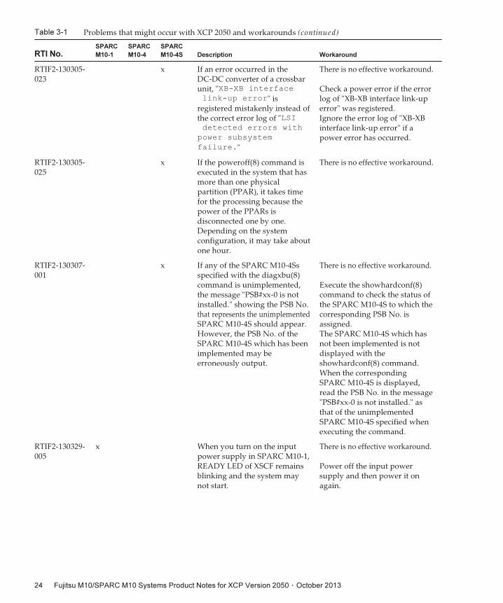
Table 3-1 Problems that might occur with XCP 2050 and workarounds (continued)
RTI No.
SPARC
M10-1
SPARC
M10-4
SPARC
M10-4S Description Workaround
RTIF2-130305-023
x If an error occurred in theDC-DC converter of a crossbarunit, "XB-XB interface
link-up error" isregistered mistakenly instead ofthe correct error log of "LSIdetected errors with
power subsystem
failure."
There is no effective workaround.
Check a power error if the errorlog of "XB-XB interface link-uperror" was registered.Ignore the error log of "XB-XBinterface link-up error" if apower error has occurred.
RTIF2-130305-025
x If the poweroff(8) command isexecuted in the system that hasmore than one physicalpartition (PPAR), it takes timefor the processing because thepower of the PPARs isdisconnected one by one.Depending on the systemconfiguration, it may take aboutone hour.
There is no effective workaround.
RTIF2-130307-001
x If any of the SPARC M10-4Ssspecified with the diagxbu(8)command is unimplemented,the message "PSB#xx-0 is notinstalled." showing the PSB No.that represents the unimplementedSPARC M10-4S should appear.However, the PSB No. of theSPARC M10-4S which has beenimplemented may beerroneously output.
There is no effective workaround.
Execute the showhardconf(8)command to check the status ofthe SPARC M10-4S to which thecorresponding PSB No. isassigned.The SPARC M10-4S which hasnot been implemented is notdisplayed with theshowhardconf(8) command.When the correspondingSPARC M10-4S is displayed,read the PSB No. in the message"PSB#xx-0 is not installed." asthat of the unimplementedSPARC M10-4S specified whenexecuting the command.
RTIF2-130329-005
x When you turn on the inputpower supply in SPARC M10-1,READY LED of XSCF remainsblinking and the system maynot start.
There is no effective workaround.
Power off the input powersupply and then power it onagain.
Fujitsu M10/SPARC M10 Systems Product Notes for XCP Version 2050 ・ October 201324
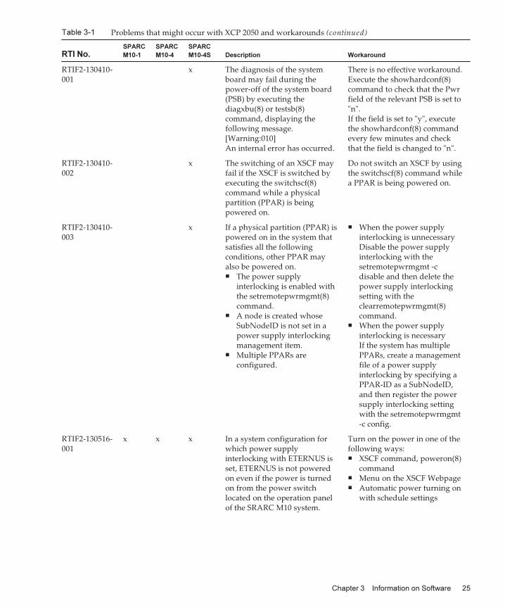
Table 3-1 Problems that might occur with XCP 2050 and workarounds (continued)
RTI No.
SPARC
M10-1
SPARC
M10-4
SPARC
M10-4S Description Workaround
RTIF2-130410-001
x The diagnosis of the systemboard may fail during thepower-off of the system board(PSB) by executing thediagxbu(8) or testsb(8)command, displaying thefollowing message.[Warning:010]An internal error has occurred.
There is no effective workaround.Execute the showhardconf(8)command to check that the Pwrfield of the relevant PSB is set to"n".If the field is set to "y", executethe showhardconf(8) commandevery few minutes and checkthat the field is changed to "n".
RTIF2-130410-002
x The switching of an XSCF mayfail if the XSCF is switched byexecuting the switchscf(8)command while a physicalpartition (PPAR) is beingpowered on.
Do not switch an XSCF by usingthe switchscf(8) command whilea PPAR is being powered on.
RTIF2-130410-003
x If a physical partition (PPAR) ispowered on in the system thatsatisfies all the followingconditions, other PPAR mayalso be powered on.■ The power supply
interlocking is enabled withthe setremotepwrmgmt(8)command.
■ A node is created whoseSubNodeID is not set in apower supply interlockingmanagement item.
■ Multiple PPARs areconfigured.
■ When the power supplyinterlocking is unnecessaryDisable the power supplyinterlocking with thesetremotepwrmgmt -cdisable and then delete thepower supply interlockingsetting with theclearremotepwrmgmt(8)command.
■ When the power supplyinterlocking is necessaryIf the system has multiplePPARs, create a managementfile of a power supplyinterlocking by specifying aPPAR-ID as a SubNodeID,and then register the powersupply interlocking settingwith the setremotepwrmgmt-c config.
RTIF2-130516-001
x x x In a system configuration forwhich power supplyinterlocking with ETERNUS isset, ETERNUS is not poweredon even if the power is turnedon from the power switchlocated on the operation panelof the SRARC M10 system.
Turn on the power in one of thefollowing ways:■ XSCF command, poweron(8)
command■ Menu on the XSCF Webpage■ Automatic power turning on
with schedule settings
Chapter 3 Information on Software 25
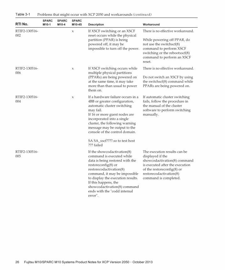
Table 3-1 Problems that might occur with XCP 2050 and workarounds (continued)
RTI No.
SPARC
M10-1
SPARC
M10-4
SPARC
M10-4S Description Workaround
RTIF2-130516-002
x If XSCF switching or an XSCFreset occurs while the physicalpartition (PPAR) is beingpowered off, it may beimpossible to turn off the power.
There is no effective workaround.
While powering off PPAR, donot use the switchscf(8)command to perform XSCFswitching or the rebootxscf(8)command to perform an XSCFreset.
RTIF2-130516-006
x If XSCF switching occurs whilemultiple physical partitions(PPARs) are being powered onat the same time, it may takemore than than usual to powerthem on.
There is no effective workaround.
Do not switch an XSCF by usingthe switchscf(8) command whilePPARs are being powered on.
RTIF2-130516-004
x If a hardware failure occurs in a4BB or greater configuration,automatic cluster switchingmay fail.If 16 or more guest nodes areincorporated into a singlecluster, the following warningmessage may be output to theconsole of the control domain.
SA SA_xscf????.so to test host??? failed
If automatic cluster switchingfails, follow the procedure inthe manual of the clustersoftware to perform switchingmanually.
RTIF2-130516-005
If the showcodactivation(8)command is executed whiledata is being restored with therestoreconfig(8) orrestorecodactivation(8)command, it may be impossibleto display the execution results.If this happens, theshowcodactivation(8) commandends with the "codd internalerror".
The execution results can bedisplayed if theshowcodactivation(8) commandis executed after the executionof the restoreconfig(8) orrestorecodactivation(8)command is completed.
Fujitsu M10/SPARC M10 Systems Product Notes for XCP Version 2050 ・ October 201326
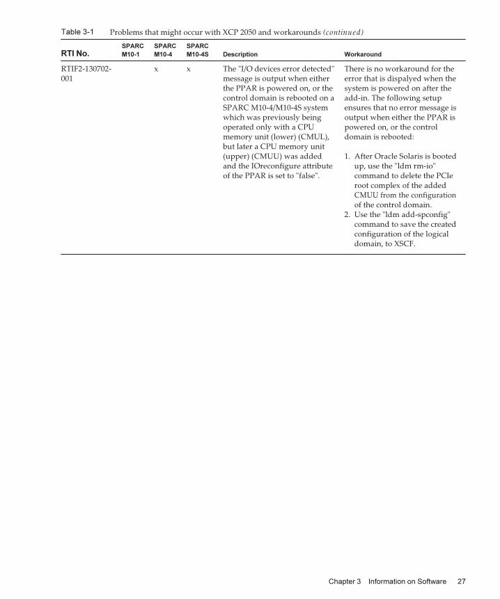
Table 3-1 Problems that might occur with XCP 2050 and workarounds (continued)
RTI No.
SPARC
M10-1
SPARC
M10-4
SPARC
M10-4S Description Workaround
RTIF2-130702-001
x x The "I/O devices error detected"message is output when eitherthe PPAR is powered on, or thecontrol domain is rebooted on aSPARC M10-4/M10-4S systemwhich was previously beingoperated only with a CPUmemory unit (lower) (CMUL),but later a CPU memory unit(upper) (CMUU) was addedand the IOreconfigure attributeof the PPAR is set to "false".
There is no workaround for theerror that is dispalyed when thesystem is powered on after theadd-in. The following setupensures that no error message isoutput when either the PPAR ispowered on, or the controldomain is rebooted:
1. After Oracle Solaris is bootedup, use the "ldm rm-io"command to delete the PCIeroot complex of the addedCMUU from the configurationof the control domain.
2. Use the "ldm add-spconfig"command to save the createdconfiguration of the logicaldomain, to XSCF.
Chapter 3 Information on Software 27
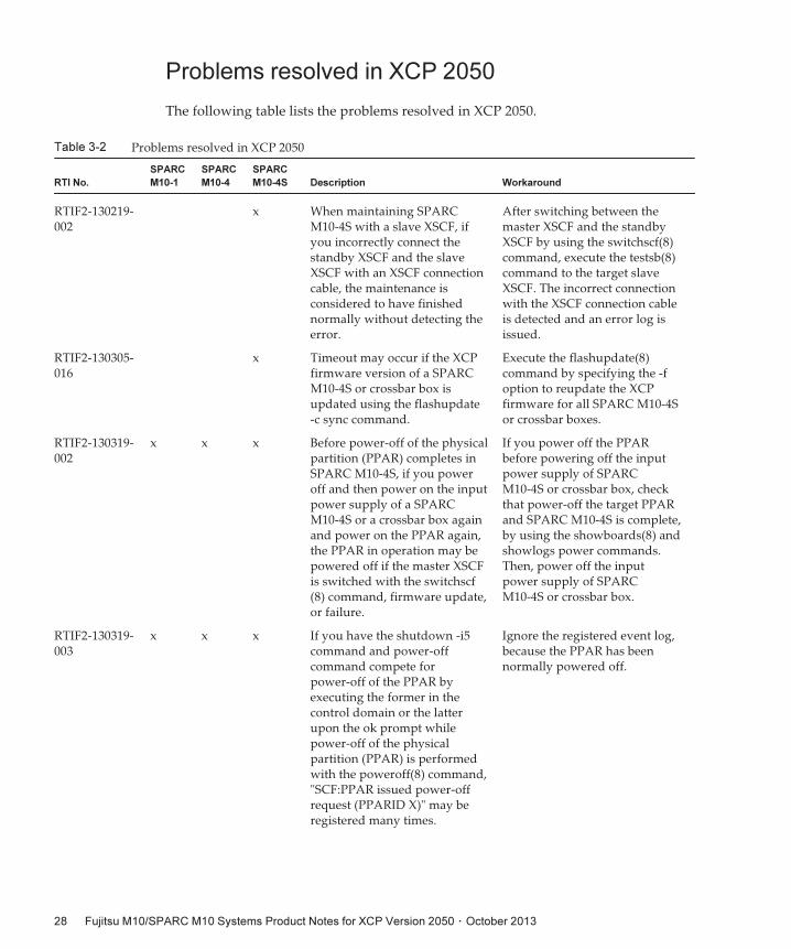
Table 3-2 Problems resolved in XCP 2050
RTI No.
SPARC
M10-1
SPARC
M10-4
SPARC
M10-4S Description Workaround
RTIF2-130219-002
x When maintaining SPARCM10-4S with a slave XSCF, ifyou incorrectly connect thestandby XSCF and the slaveXSCF with an XSCF connectioncable, the maintenance isconsidered to have finishednormally without detecting theerror.
After switching between themaster XSCF and the standbyXSCF by using the switchscf(8)command, execute the testsb(8)command to the target slaveXSCF. The incorrect connectionwith the XSCF connection cableis detected and an error log isissued.
RTIF2-130305-016
x Timeout may occur if the XCPfirmware version of a SPARCM10-4S or crossbar box isupdated using the flashupdate-c sync command.
Execute the flashupdate(8)command by specifying the -foption to reupdate the XCPfirmware for all SPARC M10-4Sor crossbar boxes.
RTIF2-130319-002
x x x Before power-off of the physicalpartition (PPAR) completes inSPARC M10-4S, if you poweroff and then power on the inputpower supply of a SPARCM10-4S or a crossbar box againand power on the PPAR again,the PPAR in operation may bepowered off if the master XSCFis switched with the switchscf(8) command, firmware update,or failure.
If you power off the PPARbefore powering off the inputpower supply of SPARCM10-4S or crossbar box, checkthat power-off the target PPARand SPARC M10-4S is complete,by using the showboards(8) andshowlogs power commands.Then, power off the inputpower supply of SPARCM10-4S or crossbar box.
RTIF2-130319-003
x x x If you have the shutdown -i5command and power-offcommand compete forpower-off of the PPAR byexecuting the former in thecontrol domain or the latterupon the ok prompt whilepower-off of the physicalpartition (PPAR) is performedwith the poweroff(8) command,"SCF:PPAR issued power-offrequest (PPARID X)" may beregistered many times.
Ignore the registered event log,because the PPAR has beennormally powered off.
Problems resolved in XCP 2050
The following table lists the problems resolved in XCP 2050.
Fujitsu M10/SPARC M10 Systems Product Notes for XCP Version 2050 ・ October 201328
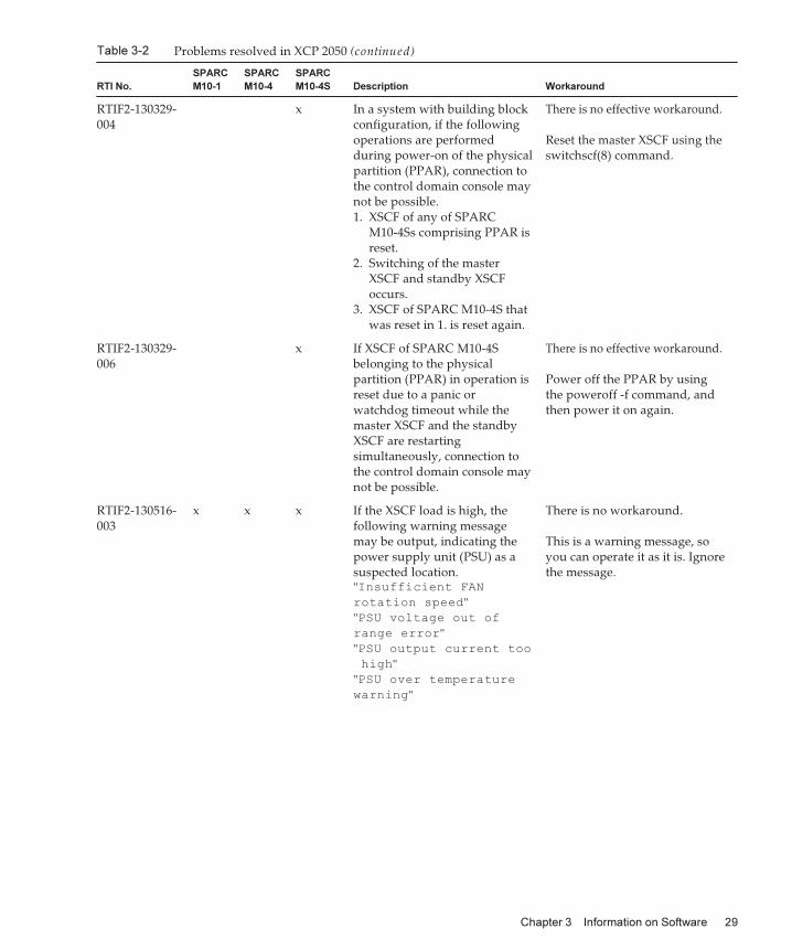
Table 3-2 Problems resolved in XCP 2050 (continued)
RTI No.
SPARC
M10-1
SPARC
M10-4
SPARC
M10-4S Description Workaround
RTIF2-130329-004
x In a system with building blockconfiguration, if the followingoperations are performedduring power-on of the physicalpartition (PPAR), connection tothe control domain console maynot be possible.1. XSCF of any of SPARC
M10-4Ss comprising PPAR isreset.
2. Switching of the masterXSCF and standby XSCFoccurs.
3. XSCF of SPARC M10-4S thatwas reset in 1. is reset again.
There is no effective workaround.
Reset the master XSCF using theswitchscf(8) command.
RTIF2-130329-006
x If XSCF of SPARC M10-4Sbelonging to the physicalpartition (PPAR) in operation isreset due to a panic orwatchdog timeout while themaster XSCF and the standbyXSCF are restartingsimultaneously, connection tothe control domain console maynot be possible.
There is no effective workaround.
Power off the PPAR by usingthe poweroff -f command, andthen power it on again.
RTIF2-130516-003
x x x If the XSCF load is high, thefollowing warning messagemay be output, indicating thepower supply unit (PSU) as asuspected location."Insufficient FAN
rotation speed""PSU voltage out of
range error""PSU output current too
high""PSU over temperature
warning"
There is no workaround.
This is a warning message, soyou can operate it as it is. Ignorethe message.
Chapter 3 Information on Software 29
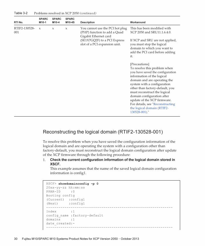
Table 3-2 Problems resolved in XCP 2050 (continued)
RTI No.
SPARC
M10-1
SPARC
M10-4
SPARC
M10-4S Description Workaround
RTIF2-130528-001
x x x You cannot use the PCI hot plug(PHP) function to add a QuadGigabit Ethernet card(SE1X7GQ2F) to a PCI Expressslot of a PCI expansion unit.
This has been modified withXCP 2050 and SRU11.1.6.4.0.
If XCP and SRU are not applied,you must stop the logicaldomain to which you want toadd the PCI card before addingit.
[Precautions]To resolve this problem whenyou have saved the configurationinformation of the logicaldomain and are operating thesystem with a configurationother than factory-default, youmust reconstruct the logicaldomain configuration afterupdate of the XCP firmware.For details, see "Reconstructingthe logical domain (RTIF2-130528-001)."
XSCF> showdomainconfig -p 020xx-yy-zz hh:mm:ss
PPAR-ID :0
Booting config
(Current) :config1
(Next) :config1
--------------------------------------------------------------
Index :1
config_name :factory-default
domains :1
date_created:-
--------------------------------------------------------------
Reconstructing the logical domain (RTIF2-130528-001)
To resolve this problem when you have saved the configuration information of thelogical domain and are operating the system with a configuration other thanfactory-default, you must reconstruct the logical domain configuration after updateof the XCP firmware through the following procedure:
1. Check the current configuration information of the logical domain stored in
XSCF.
This example assumes that the name of the saved logical domain configurationinformation is config1.
Fujitsu M10/SPARC M10 Systems Product Notes for XCP Version 2050 ・ October 201330
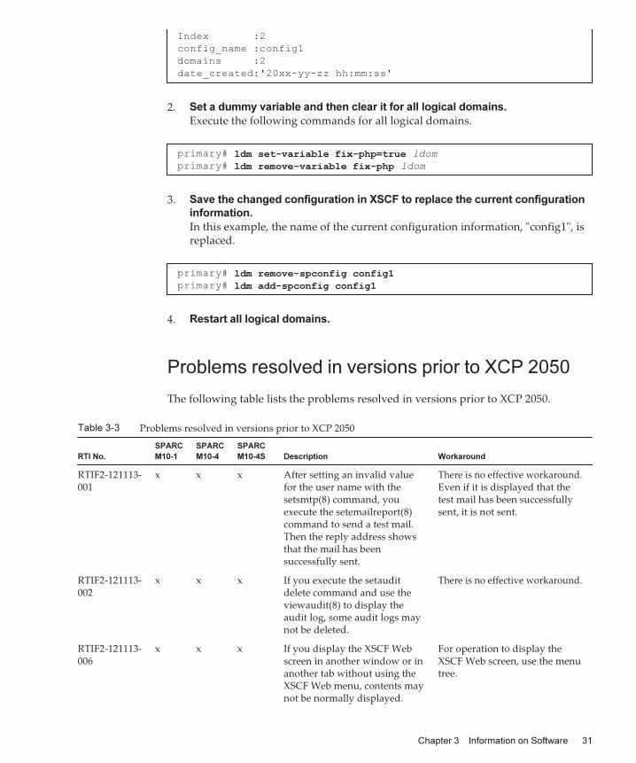
Index :2
config_name :config1
domains :2
date_created:'20xx-yy-zz hh:mm:ss'
primary# ldm set-variable fix-php=true ldom
primary# ldm remove-variable fix-php ldom
primary# ldm remove-spconfig config1primary# ldm add-spconfig config1
Table 3-3 Problems resolved in versions prior to XCP 2050
RTI No.
SPARC
M10-1
SPARC
M10-4
SPARC
M10-4S Description Workaround
RTIF2-121113-001
x x x After setting an invalid valuefor the user name with thesetsmtp(8) command, youexecute the setemailreport(8)command to send a test mail.Then the reply address showsthat the mail has beensuccessfully sent.
There is no effective workaround.Even if it is displayed that thetest mail has been successfullysent, it is not sent.
RTIF2-121113-002
x x x If you execute the setauditdelete command and use theviewaudit(8) to display theaudit log, some audit logs maynot be deleted.
There is no effective workaround.
RTIF2-121113-006
x x x If you display the XSCF Webscreen in another window or inanother tab without using theXSCF Web menu, contents maynot be normally displayed.
For operation to display theXSCF Web screen, use the menutree.
2. Set a dummy variable and then clear it for all logical domains.
Execute the following commands for all logical domains.
3. Save the changed configuration in XSCF to replace the current configuration
information.
In this example, the name of the current configuration information, "config1", isreplaced.
4. Restart all logical domains.
Problems resolved in versions prior to XCP 2050
The following table lists the problems resolved in versions prior to XCP 2050.
Chapter 3 Information on Software 31
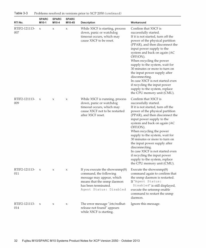
Table 3-3 Problems resolved in versions prior to XCP 2050 (continued)
RTI No.
SPARC
M10-1
SPARC
M10-4
SPARC
M10-4S Description Workaround
RTIF2-121113-007
x x x While XSCF is starting, processdown, panic or watchdogtimeout occurs, which maycause XSCF to be reset.
Confirm that XSCF issuccessfully started.If it is not started, turn off thepower of the physical partition(PPAR), and then disconnect theinput power supply to thesystem and back on again (ACOFF/ON).When recycling the powersupply to the system, wait for30 minutes or more to turn onthe input power supply afterdisconnecting.In case XSCF is not started evenif recycling the input powersupply to the system, replacethe CPU memory unit (CMU).
RTIF2-121113-009
x x x While XSCF is running, processdown, panic or watchdogtimeout occurs, which maycause XSCF not to be restartedafter XSCF reset.
Confirm that XSCF issuccessfully started.If it is not started, turn off thepower of the physical partition(PPAR), and then disconnect theinput power supply to thesystem and back on again (ACOFF/ON).When recycling the powersupply to the system, wait for30 minutes or more to turn onthe input power supply afterdisconnecting.In case XSCF is not started evenif recycling the input powersupply to the system, replacethe CPU memory unit (CMU).
RTIF2-121113-011
x x x If you execute the showsnmp(8)command, the followingmessage may appear, whichmeans that the snmp daemonhas been terminated.Agent Status: Disabled
Execute the showsnmp(8)command again to confirm thatthe snmp daemon is restarted.If "Agent Status:
Disabled" is still displayed,execute the setsnmp enablecommand to restart the snmpdaemon.
RTIF2-121113-014
x x x The error message "/etc/redhat-release not found" appearswhile XSCF is starting.
Ignore this message.
Fujitsu M10/SPARC M10 Systems Product Notes for XCP Version 2050 ・ October 201332
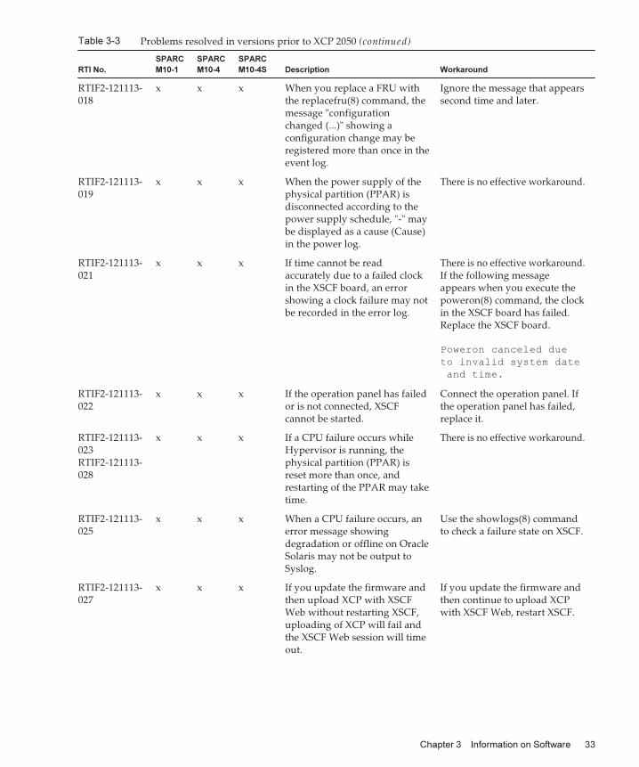
Table 3-3 Problems resolved in versions prior to XCP 2050 (continued)
RTI No.
SPARC
M10-1
SPARC
M10-4
SPARC
M10-4S Description Workaround
RTIF2-121113-018
x x x When you replace a FRU withthe replacefru(8) command, themessage "configurationchanged (...)" showing aconfiguration change may beregistered more than once in theevent log.
Ignore the message that appearssecond time and later.
RTIF2-121113-019
x x x When the power supply of thephysical partition (PPAR) isdisconnected according to thepower supply schedule, "-" maybe displayed as a cause (Cause)in the power log.
There is no effective workaround.
RTIF2-121113-021
x x x If time cannot be readaccurately due to a failed clockin the XSCF board, an errorshowing a clock failure may notbe recorded in the error log.
There is no effective workaround.If the following messageappears when you execute thepoweron(8) command, the clockin the XSCF board has failed.Replace the XSCF board.
Poweron canceled due
to invalid system date
and time.
RTIF2-121113-022
x x x If the operation panel has failedor is not connected, XSCFcannot be started.
Connect the operation panel. Ifthe operation panel has failed,replace it.
RTIF2-121113-023RTIF2-121113-028
x x x If a CPU failure occurs whileHypervisor is running, thephysical partition (PPAR) isreset more than once, andrestarting of the PPAR may taketime.
There is no effective workaround.
RTIF2-121113-025
x x x When a CPU failure occurs, anerror message showingdegradation or offline on OracleSolaris may not be output toSyslog.
Use the showlogs(8) commandto check a failure state on XSCF.
RTIF2-121113-027
x x x If you update the firmware andthen upload XCP with XSCFWeb without restarting XSCF,uploading of XCP will fail andthe XSCF Web session will timeout.
If you update the firmware andthen continue to upload XCPwith XSCF Web, restart XSCF.
Chapter 3 Information on Software 33
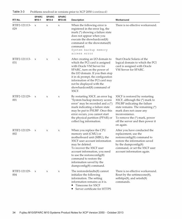
Table 3-3 Problems resolved in versions prior to XCP 2050 (continued)
RTI No.
SPARC
M10-1
SPARC
M10-4
SPARC
M10-4S Description Workaround
RTIF2-121113-029
x x x When the following error isregistered in the error log, themark (*) showing a failure statedoes not appear when youexecute the showhardconf(8)command or the showstatus(8)command.System backup memory
access error
There is no effective workaround.
RTIF2-121113-031
x x x After creating an I/O domain towhich the PCI card is assignedwith Oracle VM Server forSPARC, turn on the power ofthe I/O domain. If you then stopit in ok prompt, the configurationinformation of the PCI card maynot be displayed with theshowhardconf(8) command ofXSCF.
Start Oracle Solaris of thelogical domain to which the PCIcard is assigned with OracleVM Server for SPARC.
RTIF2-121129-001
x x x By restarting XSCF, an error log"System backup memory accesserror" may be recorded and a (*)mark indicating a failure statemay be put to PSUBP. Once thiserror occurs, you cannot startthe physical partition (PPAR) orcollect log information.
XSCF is restored by restartingXSCF, although the (*) mark toPSUBP indicating the failurestate remains. The remaining (*)mark does not cause anyinconvenience.To remove the (*) mark, poweroff the server and then power iton again.
RTIF2-121129-002
x x x When you replace the CPUmemory unit (CMU) ormotherboard unit (MBU), theXSCF user account informationmay be deleted.To recover the XSCF useraccount information, you needto use the restoreconfig(8)command to restore theinformation saved by thedumpconfig(8) command.
After you have conducted thereplacement, use therestoreconfig(8) command torestore the information savedby the dumpconfig(8)command, or set the XSCF useraccount information again.
RTIF2-121129-004
x x x The restoredefaults(8) cannotinitialize the followinginformation. The settinginformation remains as it is.■ Timezone for XSCF■ Server certificate for HTTPS
There is no effective workaround.Reset by the settimezone(8),sethttps(8), and setssh(8)commands.
Fujitsu M10/SPARC M10 Systems Product Notes for XCP Version 2050 ・ October 201334
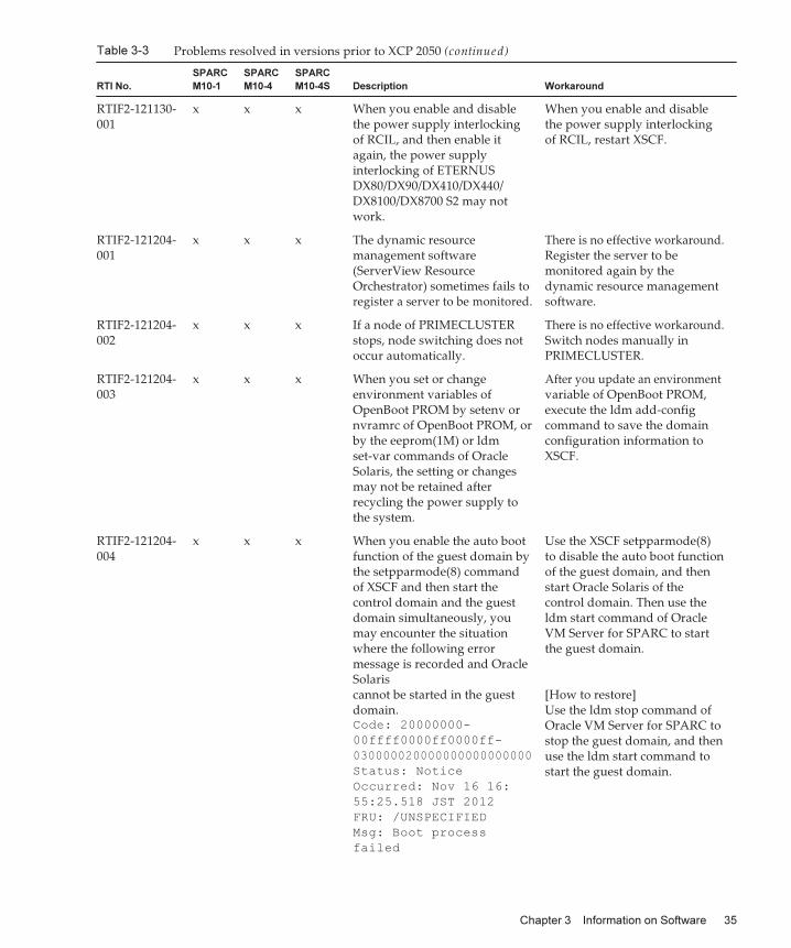
Table 3-3 Problems resolved in versions prior to XCP 2050 (continued)
RTI No.
SPARC
M10-1
SPARC
M10-4
SPARC
M10-4S Description Workaround
RTIF2-121130-001
x x x When you enable and disablethe power supply interlockingof RCIL, and then enable itagain, the power supplyinterlocking of ETERNUSDX80/DX90/DX410/DX440/DX8100/DX8700 S2 may notwork.
When you enable and disablethe power supply interlockingof RCIL, restart XSCF.
RTIF2-121204-001
x x x The dynamic resourcemanagement software(ServerView ResourceOrchestrator) sometimes fails toregister a server to be monitored.
There is no effective workaround.Register the server to bemonitored again by thedynamic resource managementsoftware.
RTIF2-121204-002
x x x If a node of PRIMECLUSTERstops, node switching does notoccur automatically.
There is no effective workaround.Switch nodes manually inPRIMECLUSTER.
RTIF2-121204-003
x x x When you set or changeenvironment variables ofOpenBoot PROM by setenv ornvramrc of OpenBoot PROM, orby the eeprom(1M) or ldmset-var commands of OracleSolaris, the setting or changesmay not be retained afterrecycling the power supply tothe system.
After you update an environmentvariable of OpenBoot PROM,execute the ldm add-configcommand to save the domainconfiguration information toXSCF.
RTIF2-121204-004
x x x When you enable the auto bootfunction of the guest domain bythe setpparmode(8) commandof XSCF and then start thecontrol domain and the guestdomain simultaneously, youmay encounter the situationwhere the following errormessage is recorded and OracleSolariscannot be started in the guestdomain.Code: 20000000-
00ffff0000ff0000ff-
030000020000000000000000
Status: Notice
Occurred: Nov 16 16:
55:25.518 JST 2012
FRU: /UNSPECIFIED
Msg: Boot process
failed
Use the XSCF setpparmode(8)to disable the auto boot functionof the guest domain, and thenstart Oracle Solaris of thecontrol domain. Then use theldm start command of OracleVM Server for SPARC to startthe guest domain.
[How to restore]Use the ldm stop command ofOracle VM Server for SPARC tostop the guest domain, and thenuse the ldm start command tostart the guest domain.
Chapter 3 Information on Software 35
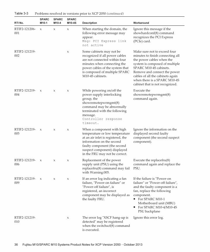
Table 3-3 Problems resolved in versions prior to XCP 2050 (continued)
RTI No.
SPARC
M10-1
SPARC
M10-4
SPARC
M10-4S Description Workaround
RTIF2-121206-001
x x x When starting the domain, thefollowing error message mayappear.Msg: PCI Express link
not active
Ignore this message if theshowhardconf(8) commandrecognizes the PCI Express(PCIe) card.
RTIF2-121219-002
x Some cabinets may not berecognized if all power cablesare not connected within fourminutes when connecting thepower cables of the system thatis composed of multiple SPARCM10-4S cabinets.
Make sure not to exceed fourminutes to finish connecting allthe power cables when thesystem is composed of multipleSPARC M10-4S cabinets.Remove and connect the powercables of all the cabinets againwhen there is a SPARC M10-4Scabinet that is not recognized.
RTIF2-121219-004
x x x While powering on/off thepower supply interlockinggroup, theshowremotepwrmgmt(8)command may be abnormallyterminated with the followingmessage.Controller response
timeout.
Execute theshowremotepwrmgmt(8)command again.
RTIF2-121219-005
x x x When a component with hightemperature or low temperatureat an air inlet is registered, theinformation on the secondfaulty component (the secondsuspect component) displayedin the FRU may not be correct.
Ignore the information on thedisplayed second faultycomponent (the second suspectcomponent).
RTIF2-121219-006
x x x Replacement of the powersupply unit (PSU) using thereplacefru(8) command may failwith Warning:005.
Execute the replacefru(8)command again and replace thePSU.
RTIF2-121219-009
x x x If an error log indicating a fanfailure, "Power-on failure" or"Power-off failure", isregistered, an incorrectcomponent may be displayed asthe faulty FRU.
If the failure is "Power-onfailure" or "Power-off failure",and the faulty component is afan, replace the followingcomponent.■ For SPARC M10-1
Motherboard unit (MBU)■ For SPARC M10-4/M10-4S
PSU backplane
RTIF2-121219-010
x The error log "XSCF hang-up isdetected" may be registeredwhen the switchscf(8) commandis executed.
Ignore this error log.
Fujitsu M10/SPARC M10 Systems Product Notes for XCP Version 2050 ・ October 201336
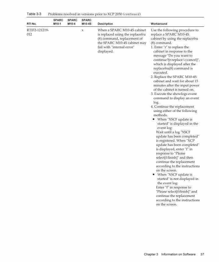
Table 3-3 Problems resolved in versions prior to XCP 2050 (continued)
RTI No.
SPARC
M10-1
SPARC
M10-4
SPARC
M10-4S Description Workaround
RTIF2-121219-012
x When a SPARC M10-4S cabinetis replaced using the replacefru(8) command, replacement ofthe SPARC M10-4S cabinet mayfail with "internal error"displayed.
Use the following procedure toreplace a SPARC M10-4Scabinet by using the replacefru(8) command.1. Enter "r" to replace the
cabinet in response to themessage "Do you want tocontinue?[r:replace|c:cancel]",which is displayed after thereplacefru(8) command isexecuted.
2. Replace the SPARC M10-4Scabinet and wait for about 15minutes after the input powerof the cabinet is turned on.
3. Execute the showlogs eventcommand to display an eventlog.
4. Continue the replacementusing either of the followingmethods.■ When "XSCF update is
started" is displayed in theevent log:
Wait until a log "XSCFupdate has been completed"is registered. When "XCPupdate has been completed"is displayed, enter "f" inresponse to "Pleaseselect[f:finish]" and thencontinue the replacementaccording to the instructionson the screen.
■ When "XSCF update isstarted" is not displayed inthe event log:
Enter "f" in response to"Please select[f:finish]" andcontinue the replacementaccording to the instructionson the screen.
Chapter 3 Information on Software 37
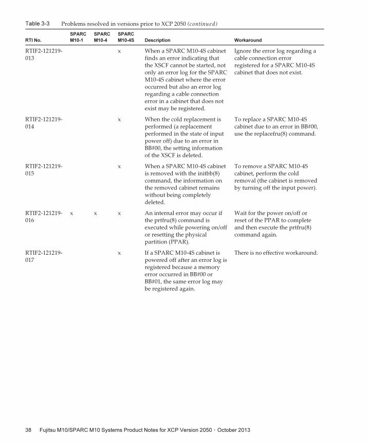
Table 3-3 Problems resolved in versions prior to XCP 2050 (continued)
RTI No.
SPARC
M10-1
SPARC
M10-4
SPARC
M10-4S Description Workaround
RTIF2-121219-013
x When a SPARC M10-4S cabinetfinds an error indicating thatthe XSCF cannot be started, notonly an error log for the SPARCM10-4S cabinet where the erroroccurred but also an error logregarding a cable connectionerror in a cabinet that does notexist may be registered.
Ignore the error log regarding acable connection errorregistered for a SPARC M10-4Scabinet that does not exist.
RTIF2-121219-014
x When the cold replacement isperformed (a replacementperformed in the state of inputpower off) due to an error inBB#00, the setting informationof the XSCF is deleted.
To replace a SPARC M10-4Scabinet due to an error in BB#00,use the replacefru(8) command.
RTIF2-121219-015
x When a SPARC M10-4S cabinetis removed with the initbb(8)command, the information onthe removed cabinet remainswithout being completelydeleted.
To remove a SPARC M10-4Scabinet, perform the coldremoval (the cabinet is removedby turning off the input power).
RTIF2-121219-016
x x x An internal error may occur ifthe prtfru(8) command isexecuted while powering on/offor resetting the physicalpartition (PPAR).
Wait for the power on/off orreset of the PPAR to completeand then execute the prtfru(8)command again.
RTIF2-121219-017
x If a SPARC M10-4S cabinet ispowered off after an error log isregistered because a memoryerror occurred in BB#00 orBB#01, the same error log maybe registered again.
There is no effective workaround.
Fujitsu M10/SPARC M10 Systems Product Notes for XCP Version 2050 ・ October 201338
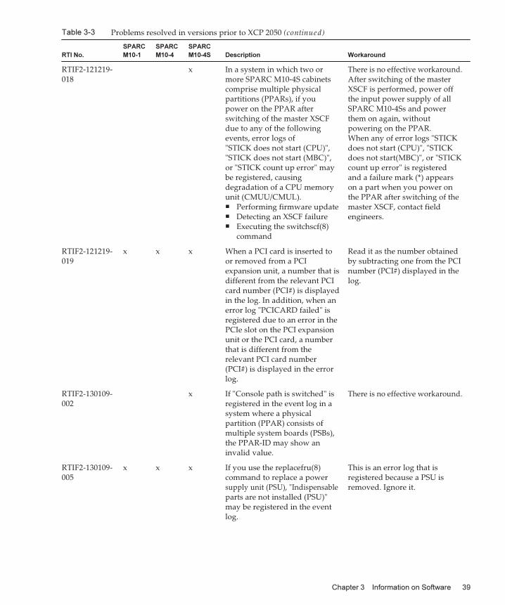
Table 3-3 Problems resolved in versions prior to XCP 2050 (continued)
RTI No.
SPARC
M10-1
SPARC
M10-4
SPARC
M10-4S Description Workaround
RTIF2-121219-018
x In a system in which two ormore SPARC M10-4S cabinetscomprise multiple physicalpartitions (PPARs), if youpower on the PPAR afterswitching of the master XSCFdue to any of the followingevents, error logs of"STICK does not start (CPU)","STICK does not start (MBC)",or "STICK count up error" maybe registered, causingdegradation of a CPU memoryunit (CMUU/CMUL).■ Performing firmware update■ Detecting an XSCF failure■ Executing the switchscf(8)
command
There is no effective workaround.After switching of the masterXSCF is performed, power offthe input power supply of allSPARC M10-4Ss and powerthem on again, withoutpowering on the PPAR.When any of error logs "STICKdoes not start (CPU)", "STICKdoes not start(MBC)", or "STICKcount up error" is registeredand a failure mark (*) appearson a part when you power onthe PPAR after switching of themaster XSCF, contact fieldengineers.
RTIF2-121219-019
x x x When a PCI card is inserted toor removed from a PCIexpansion unit, a number that isdifferent from the relevant PCIcard number (PCI#) is displayedin the log. In addition, when anerror log "PCICARD failed" isregistered due to an error in thePCIe slot on the PCI expansionunit or the PCI card, a numberthat is different from therelevant PCI card number(PCI#) is displayed in the errorlog.
Read it as the number obtainedby subtracting one from the PCInumber (PCI#) displayed in thelog.
RTIF2-130109-002
x If "Console path is switched" isregistered in the event log in asystem where a physicalpartition (PPAR) consists ofmultiple system boards (PSBs),the PPAR-ID may show aninvalid value.
There is no effective workaround.
RTIF2-130109-005
x x x If you use the replacefru(8)command to replace a powersupply unit (PSU), "Indispensableparts are not installed (PSU)"may be registered in the eventlog.
This is an error log that isregistered because a PSU isremoved. Ignore it.
Chapter 3 Information on Software 39
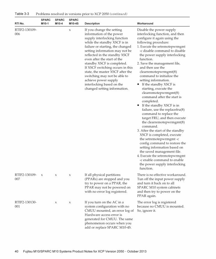
Table 3-3 Problems resolved in versions prior to XCP 2050 (continued)
RTI No.
SPARC
M10-1
SPARC
M10-4
SPARC
M10-4S Description Workaround
RTIF2-130109-006
x If you change the settinginformation of the powersupply interlocking functionwhile the standby XSCF is infailure or starting, the changedsetting information may not bereflected in the standby XSCFeven after the start of thestandby XSCF is completed.If XSCF switching occurs in thisstate, the master XSCF after theswitching may not be able toachieve power supplyinterlocking based on thechanged setting information.
Disable the power supplyinterlocking function, and thenconfigure it again using thefollowing procedure:1. Execute the setremotepwrmgmt
-c disable command to disablethe power supply interlockingfunction.
2. Save the management file,and then use theclearremotepwrmgmt(8)command to initialize thesetting information.
■ If the standby XSCF isstarting, execute theclearremotepwrmgmt(8)command after the start iscompleted.
■ If the standby XSCF is infailure, use the replacefru(8)command to replace thetarget FRU, and then executethe clearremotepwrmgmt(8)command.
3. After the start of the standbyXSCF is completed, executethe setremotepwrmgmt -cconfig command to restore thesetting information based onthe saved management file.
4. Execute the setremotepwrmgmt-c enable command to enablethe power supply interlockingfunction.
RTIF2-130109-007
x x x If all physical partitions(PPARs) are stopped and youtry to power on a PPAR, thePPAR may not be powered onwith no error log registered.
There is no effective workaround.Tun off the input power supplyand turn it back on to allSPARC M10 system cabinetsand then try to power on thePPAR again.
RTIF2-130130-001
x x If you turn on the AC in asystem configuration with noCMUU mounted, an error log ofHardware access error isgenerated for CMUU. The samephenomenon occurs when youadd or replace SPARC M10-4S.
The error log is registeredbecause no CMUU is mounted.So, ignore it.
Fujitsu M10/SPARC M10 Systems Product Notes for XCP Version 2050 ・ October 201340
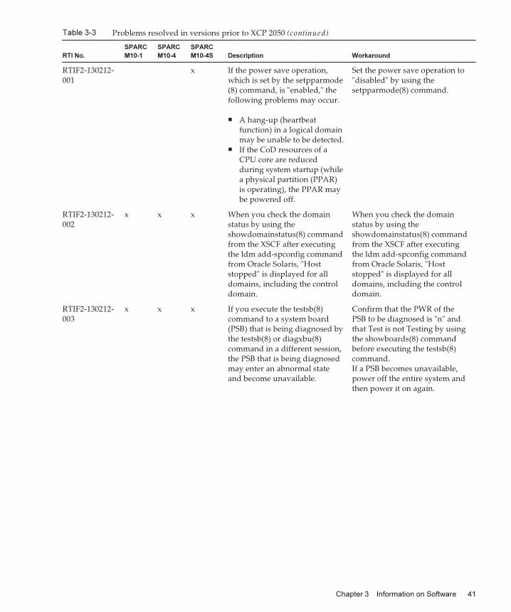
Table 3-3 Problems resolved in versions prior to XCP 2050 (continued)
RTI No.
SPARC
M10-1
SPARC
M10-4
SPARC
M10-4S Description Workaround
RTIF2-130212-001
x If the power save operation,which is set by the setpparmode(8) command, is "enabled," thefollowing problems may occur.
■ A hang-up (heartbeatfunction) in a logical domainmay be unable to be detected.
■ If the CoD resources of aCPU core are reducedduring system startup (whilea physical partition (PPAR)is operating), the PPAR maybe powered off.
Set the power save operation to"disabled" by using thesetpparmode(8) command.
RTIF2-130212-002
x x x When you check the domainstatus by using theshowdomainstatus(8) commandfrom the XSCF after executingthe ldm add-spconfig commandfrom Oracle Solaris, "Hoststopped" is displayed for alldomains, including the controldomain.
When you check the domainstatus by using theshowdomainstatus(8) commandfrom the XSCF after executingthe ldm add-spconfig commandfrom Oracle Solaris, "Hoststopped" is displayed for alldomains, including the controldomain.
RTIF2-130212-003
x x x If you execute the testsb(8)command to a system board(PSB) that is being diagnosed bythe testsb(8) or diagxbu(8)command in a different session,the PSB that is being diagnosedmay enter an abnormal stateand become unavailable.
Confirm that the PWR of thePSB to be diagnosed is "n" andthat Test is not Testing by usingthe showboards(8) commandbefore executing the testsb(8)command.If a PSB becomes unavailable,power off the entire system andthen power it on again.
Chapter 3 Information on Software 41
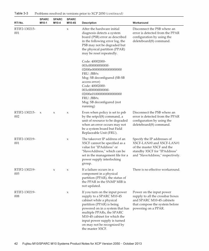
Table 3-3 Problems resolved in versions prior to XCP 2050 (continued)
RTI No.
SPARC
M10-1
SPARC
M10-4
SPARC
M10-4S Description Workaround
RTIF2-130215-001
x After the hardware initialdiagnosis detects a systemboard (PSB) error as describedin the following error log, thePSB may not be degraded butthe physical partition (PPAR)may be reset repeatedly.
Code: 40002000-003cff0000ff0000ff-02000e000000000000000000FRU: /BB#xMsg: SB deconfigured (SB-SBaccess error)Code: 40002000-003cff0000ff0000ff-02000e010000000000000000FRU: /BB#xMsg: SB deconfigured (notrunning)
Disconnect the PSB where anerror is detected from the PPARconfiguration by using thedeleteboard(8) command.
RTIF2-130215-002
x x x Even when policy is set to psbby the setpcl(8) command, aunit of resource to be degradedwhen an error occurs may notbe a system board but FieldReplaceable Unit (FRU).
Disconnect the PSB where anerror is detected from the PPARconfiguration by using thedeleteboard(8) command.
RTIF2-130219-001
x The takeover IP address of anXSCF cannot be specified as avalue for "IPAddress" or"SlaveAddress," which can beset in the management file for apower supply interlockinggroup.
Specify the IP addresses ofXSCF-LAN#0 and XSCF-LAN#1of the master XSCF and thestandby XSCF for "IPAddress"and "SlaveAddress," respectively.
RTIF2-130219-005
x x If a failure occurs in acomponent in a physicalpartition (PPAR), the status ofthe PPAR in the SNMP MIB isnot updated.
There is no effective workaround.
RTIF2-130219-008
x If you turn on the input powersupply to a SPARC M10-4Scabinet while a physicalpartition (PPAR) is beingpowered on in a system that hasmultiple PPARs, the SPARCM10-4S cabinet for which theinput power supply is turnedon may not be recognized bythe master XSCF.
Power on the input powersupply to all the crossbar boxesand SPARC M10-4S cabinetsthat compose the system beforepowering on a PPAR.
Fujitsu M10/SPARC M10 Systems Product Notes for XCP Version 2050 ・ October 201342
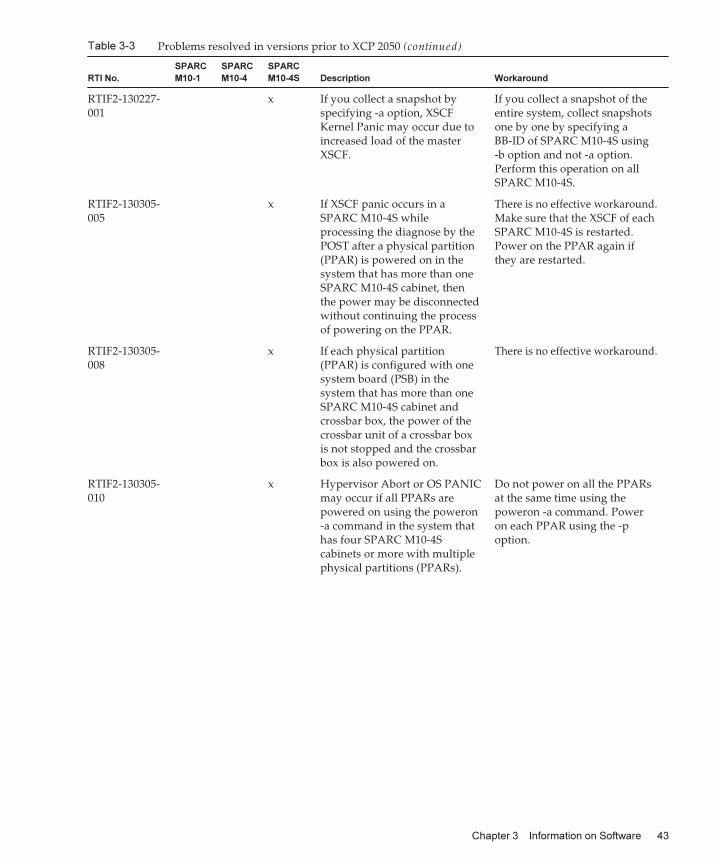
Table 3-3 Problems resolved in versions prior to XCP 2050 (continued)
RTI No.
SPARC
M10-1
SPARC
M10-4
SPARC
M10-4S Description Workaround
RTIF2-130227-001
x If you collect a snapshot byspecifying -a option, XSCFKernel Panic may occur due toincreased load of the masterXSCF.
If you collect a snapshot of theentire system, collect snapshotsone by one by specifying aBB-ID of SPARC M10-4S using-b option and not -a option.Perform this operation on allSPARC M10-4S.
RTIF2-130305-005
x If XSCF panic occurs in aSPARC M10-4S whileprocessing the diagnose by thePOST after a physical partition(PPAR) is powered on in thesystem that has more than oneSPARC M10-4S cabinet, thenthe power may be disconnectedwithout continuing the processof powering on the PPAR.
There is no effective workaround.Make sure that the XSCF of eachSPARC M10-4S is restarted.Power on the PPAR again ifthey are restarted.
RTIF2-130305-008
x If each physical partition(PPAR) is configured with onesystem board (PSB) in thesystem that has more than oneSPARC M10-4S cabinet andcrossbar box, the power of thecrossbar unit of a crossbar boxis not stopped and the crossbarbox is also powered on.
There is no effective workaround.
RTIF2-130305-010
x Hypervisor Abort or OS PANICmay occur if all PPARs arepowered on using the poweron-a command in the system thathas four SPARC M10-4Scabinets or more with multiplephysical partitions (PPARs).
Do not power on all the PPARsat the same time using thepoweron -a command. Poweron each PPAR using the -poption.
Chapter 3 Information on Software 43
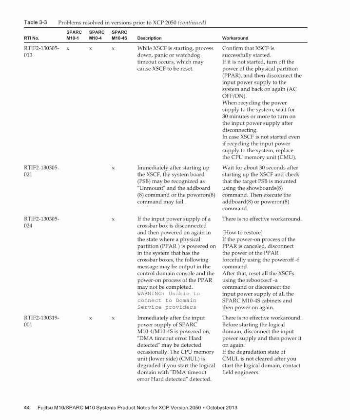
Table 3-3 Problems resolved in versions prior to XCP 2050 (continued)
RTI No.
SPARC
M10-1
SPARC
M10-4
SPARC
M10-4S Description Workaround
RTIF2-130305-013
x x x While XSCF is starting, processdown, panic or watchdogtimeout occurs, which maycause XSCF to be reset.
Confirm that XSCF issuccessfully started.If it is not started, turn off thepower of the physical partition(PPAR), and then disconnect theinput power supply to thesystem and back on again (ACOFF/ON).When recycling the powersupply to the system, wait for30 minutes or more to turn onthe input power supply afterdisconnecting.In case XSCF is not started evenif recycling the input powersupply to the system, replacethe CPU memory unit (CMU).
RTIF2-130305-021
x Immediately after starting upthe XSCF, the system board(PSB) may be recognized as"Unmount" and the addboard(8) command or the poweron(8)command may fail.
Wait for about 30 seconds afterstarting up the XSCF and checkthat the target PSB is mountedusing the showboards(8)command. Then execute theaddboard(8) or poweron(8)command.
RTIF2-130305-024
x If the input power supply of acrossbar box is disconnectedand then powered on again inthe state where a physicalpartition (PPAR ) is powered onin the system that has thecrossbar boxes, the followingmessage may be output in thecontrol domain console and thepower-on process of the PPARmay not be completed.WARNING: Unable to
connect to Domain
Service providers
There is no effective workaround.
[How to restore]If the power-on process of thePPAR is canceled, disconnectthe power of the PPARforcefully using the poweroff -fcommand.After that, reset all the XSCFsusing the rebootxscf -acommand or disconnect theinput power supply of all theSPARC M10-4S cabinets andthen power on again.
RTIF2-130319-001
x x Immediately after the inputpower supply of SPARCM10-4/M10-4S is powered on,"DMA timeout error Harddetected" may be detectedoccasionally. The CPU memoryunit (lower side) (CMUL) isdegraded if you start the logicaldomain with "DMA timeouterror Hard detected" detected.
There is no effective workaround.Before starting the logicaldomain, disconnect the inputpower supply and then power iton again.If the degradation state ofCMUL is not cleared after youstart the logical domain, contactfield engineers.
Fujitsu M10/SPARC M10 Systems Product Notes for XCP Version 2050 ・ October 201344
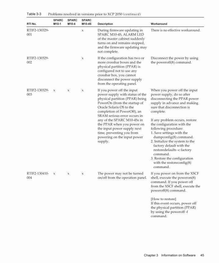
Table 3-3 Problems resolved in versions prior to XCP 2050 (continued)
RTI No.
SPARC
M10-1
SPARC
M10-4
SPARC
M10-4S Description Workaround
RTIF2-130329-001
x During firmware updating inSPARC M10-4S, ALARM LEDof the master cabinet suddenlyturns on and remains stopped,and the firmware updating maynot complete.
There is no effective workaround.
RTIF2-130329-002
x If the configuration has two ormore crossbar boxes and thephysical partition (PPAR) isconfigured not to use anycrossbar box, you cannotdisconnect the power supplyfrom the operating panel.
Disconnect the power by usingthe poweroff(8) command.
RTIF2-130329-003
x x x If you power off the inputpower supply with status of thephysical partition (PPAR) beingPowerOn (from the startup ofOracle Solaris OS to thecompletion of PowerOff), anSRAM serious error occurs inany of the SPARC M10-4Ss inthe PPAR when you power onthe input power supply nexttime, preventing you frompowering on the input powersupply.
When you power off the inputpower supply, do so afterdisconnecting the PPAR powersupply in advance and makingsure that disconnection iscomplete.
If any problem occurs, restorethe configuration with thefollowing procedure:1. Save settings with the
dumpconfig(8) command.2. Initialize the system to the
factory default with therestoredefaults -c factorycommand.
3. Restore the configurationwith the restoreconfig(8)command.
RTIF2-130410-004
x x x The power may not be turnedon/off from the operation panel.
If you power on from the XSCFshell, execute the poweron(8)command. If you power offfrom the XSCF shell, execute thepoweroff(8) command.
[How to restore]If this event occurs, power offthe physical partition (PPAR)by using the poweroff -fcommand.
Chapter 3 Information on Software 45
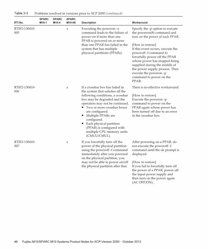
Table 3-3 Problems resolved in versions prior to XCP 2050 (continued)
RTI No.
SPARC
M10-1
SPARC
M10-4
SPARC
M10-4S Description Workaround
RTIF2-130410-005
x Executing the poweron -acommand leads to the failure ofpower-on if more than onePPAR is powered on or morethan one PPAR has failed in thesystem that has multiplephysical partitions (PPARs).
Specify the -p option to executethe poweron(8) command andturn on the power of each PPAR.
[How to restore]If this event occurs, execute thepoweroff -f command toforcefully power off the PPARwhose power has stopped beingsupplied during the middle ofthe power supply process. Thenexecute the poweron -pcommand to power on thePPAR.
RTIF2-130410-006
x If a crossbar box has failed inthe system that satisfies all thefollowing conditions, a crossbarbox may be degraded and theoperation may not be continued.■ Two or more crossbar boxes
are configured.■ Multiple PPARs are
configured.■ Each physical partition
(PPAR) is configured withmultiple CPU memory units(CMUU/CMUL).
There is no effective workaround.
[How to restore]Execute the poweron -pcommand to power on thePPAR again whose power hasbeen turned off due to an errorin the crossbar box.
RTIF2-130410-007
x If you forcefully turn off thepower of the physical partitionusing the poweroff -f commandimmediately after you poweredon the physical partition, youmay not be able to power on/offthe physical partition after that.
After powering on a PPAR, donot execute the poweroff -fcommand until the ok prompt isdisplayed.
[How to restore]If you fail to forcefully turn offthe power of a PPAR, power offthe input power supply andthen turn on the power again(AC OFF/ON).
Fujitsu M10/SPARC M10 Systems Product Notes for XCP Version 2050 ・ October 201346
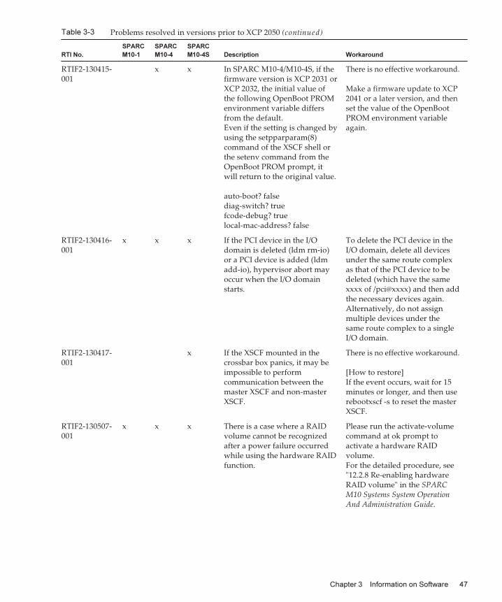
Table 3-3 Problems resolved in versions prior to XCP 2050 (continued)
RTI No.
SPARC
M10-1
SPARC
M10-4
SPARC
M10-4S Description Workaround
RTIF2-130415-001
x x In SPARC M10-4/M10-4S, if thefirmware version is XCP 2031 orXCP 2032, the initial value ofthe following OpenBoot PROMenvironment variable differsfrom the default.Even if the setting is changed byusing the setpparparam(8)command of the XSCF shell orthe setenv command from theOpenBoot PROM prompt, itwill return to the original value.
auto-boot? falsediag-switch? truefcode-debug? truelocal-mac-address? false
There is no effective workaround.
Make a firmware update to XCP2041 or a later version, and thenset the value of the OpenBootPROM environment variableagain.
RTIF2-130416-001
x x x If the PCI device in the I/Odomain is deleted (ldm rm-io)or a PCI device is added (ldmadd-io), hypervisor abort mayoccur when the I/O domainstarts.
To delete the PCI device in theI/O domain, delete all devicesunder the same route complexas that of the PCI device to bedeleted (which have the samexxxx of /pci@xxxx) and then addthe necessary devices again.Alternatively, do not assignmultiple devices under thesame route complex to a singleI/O domain.
RTIF2-130417-001
x If the XSCF mounted in thecrossbar box panics, it may beimpossible to performcommunication between themaster XSCF and non-masterXSCF.
There is no effective workaround.
[How to restore]If the event occurs, wait for 15minutes or longer, and then userebootxscf -s to reset the masterXSCF.
RTIF2-130507-001
x x x There is a case where a RAIDvolume cannot be recognizedafter a power failure occurredwhile using the hardware RAIDfunction.
Please run the activate-volumecommand at ok prompt toactivate a hardware RAIDvolume.For the detailed procedure, see"12.2.8 Re-enabling hardwareRAID volume" in the SPARCM10 Systems System OperationAnd Administration Guide.
Chapter 3 Information on Software 47
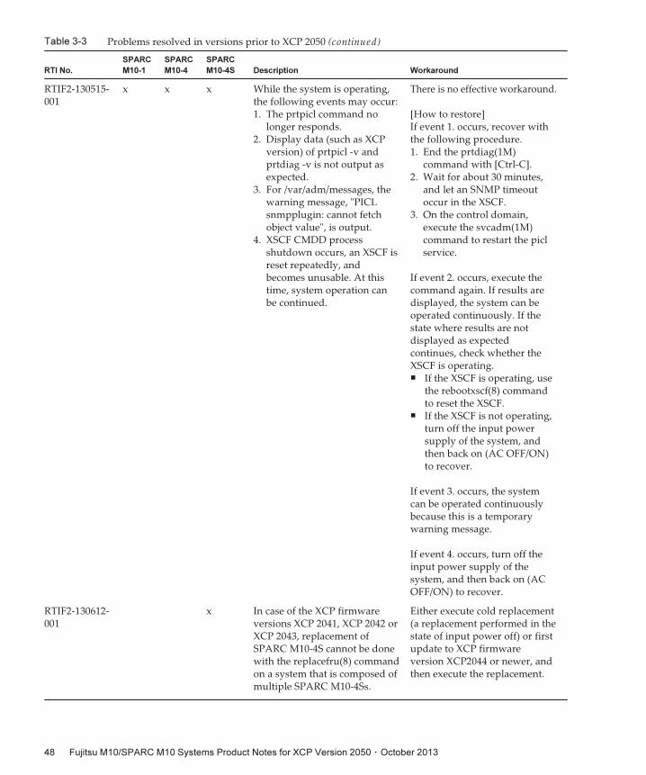
Table 3-3 Problems resolved in versions prior to XCP 2050 (continued)
RTI No.
SPARC
M10-1
SPARC
M10-4
SPARC
M10-4S Description Workaround
RTIF2-130515-001
x x x While the system is operating,the following events may occur:1. The prtpicl command no
longer responds.2. Display data (such as XCP
version) of prtpicl -v andprtdiag -v is not output asexpected.
3. For /var/adm/messages, thewarning message, "PICLsnmpplugin: cannot fetchobject value", is output.
4. XSCF CMDD processshutdown occurs, an XSCF isreset repeatedly, andbecomes unusable. At thistime, system operation canbe continued.
There is no effective workaround.
[How to restore]If event 1. occurs, recover withthe following procedure.1. End the prtdiag(1M)
command with [Ctrl-C].2. Wait for about 30 minutes,
and let an SNMP timeoutoccur in the XSCF.
3. On the control domain,execute the svcadm(1M)command to restart the piclservice.
If event 2. occurs, execute thecommand again. If results aredisplayed, the system can beoperated continuously. If thestate where results are notdisplayed as expectedcontinues, check whether theXSCF is operating.■ If the XSCF is operating, use
the rebootxscf(8) commandto reset the XSCF.
■ If the XSCF is not operating,turn off the input powersupply of the system, andthen back on (AC OFF/ON)to recover.
If event 3. occurs, the systemcan be operated continuouslybecause this is a temporarywarning message.
If event 4. occurs, turn off theinput power supply of thesystem, and then back on (ACOFF/ON) to recover.
RTIF2-130612-001
x In case of the XCP firmwareversions XCP 2041, XCP 2042 orXCP 2043, replacement ofSPARC M10-4S cannot be donewith the replacefru(8) commandon a system that is composed ofmultiple SPARC M10-4Ss.
Either execute cold replacement(a replacement performed in thestate of input power off) or firstupdate to XCP firmwareversion XCP2044 or newer, andthen execute the replacement.
Fujitsu M10/SPARC M10 Systems Product Notes for XCP Version 2050 ・ October 201348
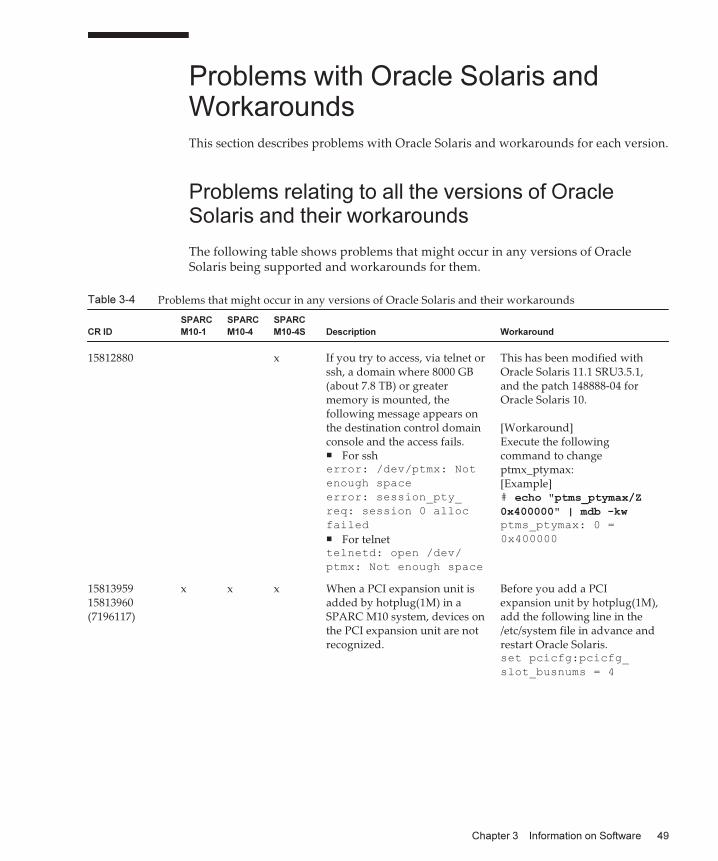
Table 3-4 Problems that might occur in any versions of Oracle Solaris and their workarounds
CR ID
SPARC
M10-1
SPARC
M10-4
SPARC
M10-4S Description Workaround
15812880 x If you try to access, via telnet orssh, a domain where 8000 GB(about 7.8 TB) or greatermemory is mounted, thefollowing message appears onthe destination control domainconsole and the access fails.■ For ssherror: /dev/ptmx: Not
enough space
error: session_pty_
req: session 0 alloc
failed■ For telnettelnetd: open /dev/
ptmx: Not enough space
This has been modified withOracle Solaris 11.1 SRU3.5.1,and the patch 148888-04 forOracle Solaris 10.
[Workaround]Execute the followingcommand to changeptmx_ptymax:[Example]# echo "ptms_ptymax/Z0x400000" | mdb -kwptms_ptymax: 0 =
0x400000
1581395915813960(7196117)
x x x When a PCI expansion unit isadded by hotplug(1M) in aSPARC M10 system, devices onthe PCI expansion unit are notrecognized.
Before you add a PCIexpansion unit by hotplug(1M),add the following line in the/etc/system file in advance andrestart Oracle Solaris.set pcicfg:pcicfg_
slot_busnums = 4
Problems with Oracle Solaris andWorkaroundsThis section describes problems with Oracle Solaris and workarounds for each version.
Problems relating to all the versions of OracleSolaris and their workarounds
The following table shows problems that might occur in any versions of OracleSolaris being supported and workarounds for them.
Chapter 3 Information on Software 49
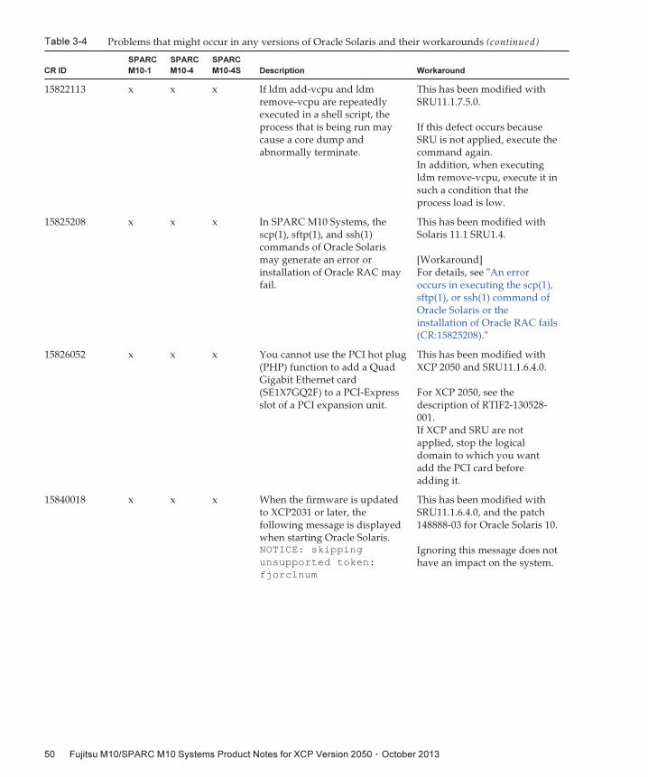
Table 3-4 Problems that might occur in any versions of Oracle Solaris and their workarounds (continued)
CR ID
SPARC
M10-1
SPARC
M10-4
SPARC
M10-4S Description Workaround
15822113 x x x If ldm add-vcpu and ldmremove-vcpu are repeatedlyexecuted in a shell script, theprocess that is being run maycause a core dump andabnormally terminate.
This has been modified withSRU11.1.7.5.0.
If this defect occurs becauseSRU is not applied, execute thecommand again.In addition, when executingldm remove-vcpu, execute it insuch a condition that theprocess load is low.
15825208 x x x In SPARC M10 Systems, thescp(1), sftp(1), and ssh(1)commands of Oracle Solarismay generate an error orinstallation of Oracle RAC mayfail.
This has been modified withSolaris 11.1 SRU1.4.
[Workaround]For details, see "An erroroccurs in executing the scp(1),sftp(1), or ssh(1) command ofOracle Solaris or theinstallation of Oracle RAC fails(CR:15825208)."
15826052 x x x You cannot use the PCI hot plug(PHP) function to add a QuadGigabit Ethernet card(SE1X7GQ2F) to a PCI-Expressslot of a PCI expansion unit.
This has been modified withXCP 2050 and SRU11.1.6.4.0.
For XCP 2050, see thedescription of RTIF2-130528-001.If XCP and SRU are notapplied, stop the logicaldomain to which you wantadd the PCI card beforeadding it.
15840018 x x x When the firmware is updatedto XCP2031 or later, thefollowing message is displayedwhen starting Oracle Solaris.NOTICE: skipping
unsupported token:
fjorclnum
This has been modified withSRU11.1.6.4.0, and the patch148888-03 for Oracle Solaris 10.
Ignoring this message does nothave an impact on the system.
Fujitsu M10/SPARC M10 Systems Product Notes for XCP Version 2050 ・ October 201350
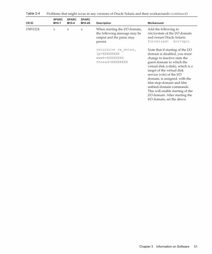
Table 3-4 Problems that might occur in any versions of Oracle Solaris and their workarounds (continued)
CR ID
SPARC
M10-1
SPARC
M10-4
SPARC
M10-4S Description Workaround
15851224 x x x When starting the I/O domain,the following message may beoutput and the panic maypersist.
recursive rw_enter,
lp=XXXXXXXX
wwwh=XXXXXXXX
thread=XXXXXXXX
Add the following to/etc/system of the I/O domainand restart Oracle Solaris:forceload: drv/vpci
Note that if starting of the I/Odomain is disabled, you mustchange to inactive state theguest domain to which thevirtual disk (vdisk), which is atarget of the virtual diskservice (vds) of the I/Odomain, is assigned, with theldm stop-domain and ldmunbind-domain commands.This will enable starting of theI/O domain. After starting theI/O domain, set the above.
Chapter 3 Information on Software 51
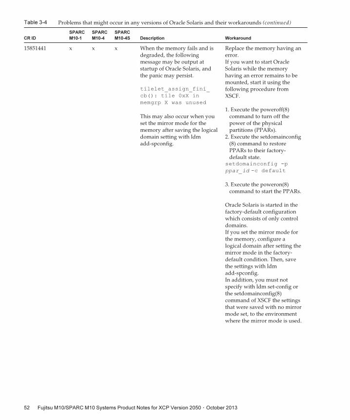
Table 3-4 Problems that might occur in any versions of Oracle Solaris and their workarounds (continued)
CR ID
SPARC
M10-1
SPARC
M10-4
SPARC
M10-4S Description Workaround
15851441 x x x When the memory fails and isdegraded, the followingmessage may be output atstartup of Oracle Solaris, andthe panic may persist.
tilelet_assign_fini_
cb(): tile 0xX in
memgrp X was unused
This may also occur when youset the mirror mode for thememory after saving the logicaldomain setting with ldmadd-spconfig.
Replace the memory having anerror.If you want to start OracleSolaris while the memoryhaving an error remains to bemounted, start it using thefollowing procedure fromXSCF.
1. Execute the poweroff(8)command to turn off thepower of the physicalpartitions (PPARs).
2. Execute the setdomainconfig(8) command to restorePPARs to their factory-default state.
setdomainconfig -p
ppar_id -c default
3. Execute the poweron(8)command to start the PPARs.
Oracle Solaris is started in thefactory-default configurationwhich consists of only controldomains.If you set the mirror mode forthe memory, configure alogical domain after setting themirror mode in the factory-default condition. Then, savethe settings with ldmadd-spconfig.In addition, you must notspecify with ldm set-config orthe setdomainconfig(8)command of XSCF the settingsthat were saved with no mirrormode set, to the environmentwhere the mirror mode is used.
Fujitsu M10/SPARC M10 Systems Product Notes for XCP Version 2050 ・ October 201352
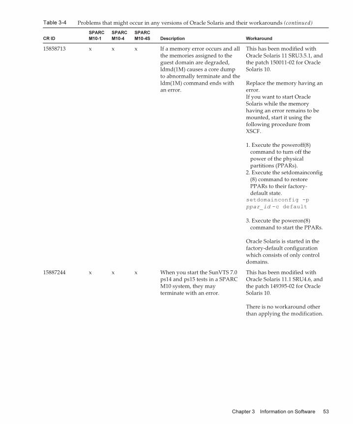
Table 3-4 Problems that might occur in any versions of Oracle Solaris and their workarounds (continued)
CR ID
SPARC
M10-1
SPARC
M10-4
SPARC
M10-4S Description Workaround
15858713 x x x If a memory error occurs and allthe memories assigned to theguest domain are degraded,ldmd(1M) causes a core dumpto abnormally terminate and theldm(1M) command ends withan error.
This has been modified withOracle Solaris 11 SRU3.5.1, andthe patch 150011-02 for OracleSolaris 10.
Replace the memory having anerror.If you want to start OracleSolaris while the memoryhaving an error remains to bemounted, start it using thefollowing procedure fromXSCF.
1. Execute the poweroff(8)command to turn off thepower of the physicalpartitions (PPARs).
2. Execute the setdomainconfig(8) command to restorePPARs to their factory-default state.
setdomainconfig -p
ppar_id -c default
3. Execute the poweron(8)command to start the PPARs.
Oracle Solaris is started in thefactory-default configurationwhich consists of only controldomains.
15887244 x x x When you start the SunVTS 7.0ps14 and ps15 tests in a SPARCM10 system, they mayterminate with an error.
This has been modified withOracle Solaris 11.1 SRU4.6, andthe patch 149395-02 for OracleSolaris 10.
There is no workaround otherthan applying the modification.
Chapter 3 Information on Software 53
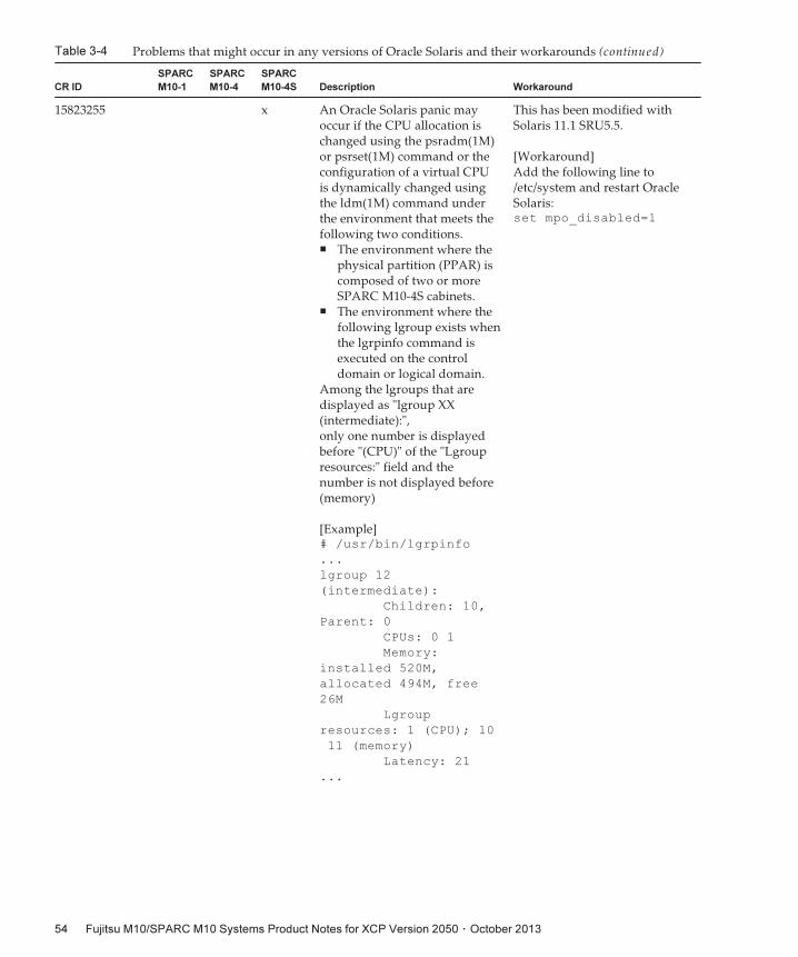
Table 3-4 Problems that might occur in any versions of Oracle Solaris and their workarounds (continued)
CR ID
SPARC
M10-1
SPARC
M10-4
SPARC
M10-4S Description Workaround
15823255 x An Oracle Solaris panic mayoccur if the CPU allocation ischanged using the psradm(1M)or psrset(1M) command or theconfiguration of a virtual CPUis dynamically changed usingthe ldm(1M) command underthe environment that meets thefollowing two conditions.■ The environment where the
physical partition (PPAR) iscomposed of two or moreSPARC M10-4S cabinets.
■ The environment where thefollowing lgroup exists whenthe lgrpinfo command isexecuted on the controldomain or logical domain.
Among the lgroups that aredisplayed as "lgroup XX(intermediate):",only one number is displayedbefore "(CPU)" of the "Lgroupresources:" field and thenumber is not displayed before(memory)
[Example]# /usr/bin/lgrpinfo
...
lgroup 12
(intermediate):
Children: 10,
Parent: 0
CPUs: 0 1
Memory:
installed 520M,
allocated 494M, free
26M
Lgroup
resources: 1 (CPU); 10
11 (memory)
Latency: 21
...
This has been modified withSolaris 11.1 SRU5.5.
[Workaround]Add the following line to/etc/system and restart OracleSolaris:set mpo_disabled=1
Fujitsu M10/SPARC M10 Systems Product Notes for XCP Version 2050 ・ October 201354
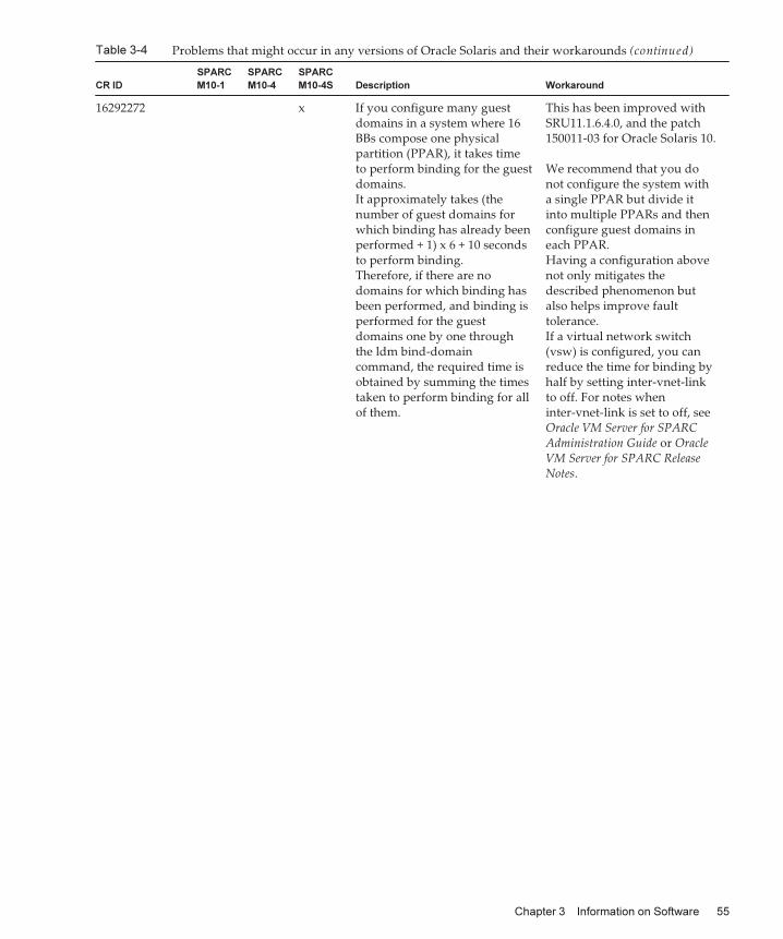
Table 3-4 Problems that might occur in any versions of Oracle Solaris and their workarounds (continued)
CR ID
SPARC
M10-1
SPARC
M10-4
SPARC
M10-4S Description Workaround
16292272 x If you configure many guestdomains in a system where 16BBs compose one physicalpartition (PPAR), it takes timeto perform binding for the guestdomains.It approximately takes (thenumber of guest domains forwhich binding has already beenperformed + 1) x 6 + 10 secondsto perform binding.Therefore, if there are nodomains for which binding hasbeen performed, and binding isperformed for the guestdomains one by one throughthe ldm bind-domaincommand, the required time isobtained by summing the timestaken to perform binding for allof them.
This has been improved withSRU11.1.6.4.0, and the patch150011-03 for Oracle Solaris 10.
We recommend that you donot configure the system witha single PPAR but divide itinto multiple PPARs and thenconfigure guest domains ineach PPAR.Having a configuration abovenot only mitigates thedescribed phenomenon butalso helps improve faulttolerance.If a virtual network switch(vsw) is configured, you canreduce the time for binding byhalf by setting inter-vnet-linkto off. For notes wheninter-vnet-link is set to off, seeOracle VM Server for SPARCAdministration Guide or OracleVM Server for SPARC ReleaseNotes.
Chapter 3 Information on Software 55
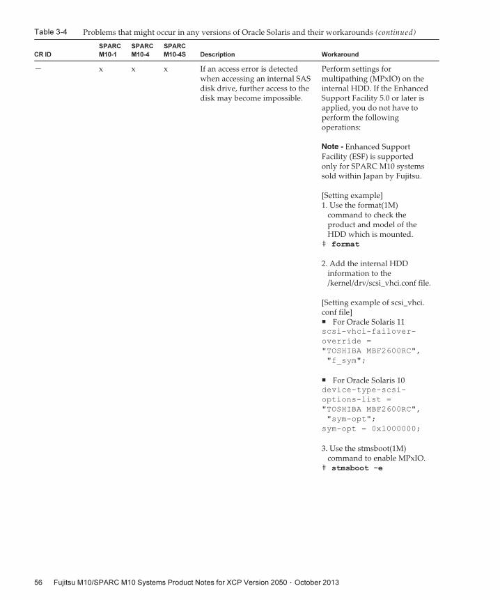
Table 3-4 Problems that might occur in any versions of Oracle Solaris and their workarounds (continued)
CR ID
SPARC
M10-1
SPARC
M10-4
SPARC
M10-4S Description Workaround
- x x x If an access error is detectedwhen accessing an internal SASdisk drive, further access to thedisk may become impossible.
Perform settings formultipathing (MPxIO) on theinternal HDD. If the EnhancedSupport Facility 5.0 or later isapplied, you do not have toperform the followingoperations:
Note - Enhanced SupportFacility (ESF) is supportedonly for SPARC M10 systemssold within Japan by Fujitsu.
[Setting example]1. Use the format(1M)
command to check theproduct and model of theHDD which is mounted.
# format
2. Add the internal HDDinformation to the/kernel/drv/scsi_vhci.conf file.
[Setting example of scsi_vhci.conf file]■ For Oracle Solaris 11scsi-vhci-failover-
override =
"TOSHIBA MBF2600RC",
"f_sym";
■ For Oracle Solaris 10device-type-scsi-
options-list =
"TOSHIBA MBF2600RC",
"sym-opt";
sym-opt = 0x1000000;
3. Use the stmsboot(1M)command to enable MPxIO.
# stmsboot -e
Fujitsu M10/SPARC M10 Systems Product Notes for XCP Version 2050 ・ October 201356
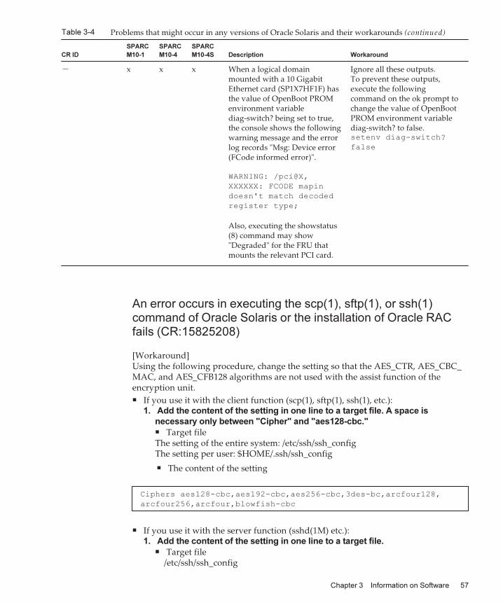
Table 3-4 Problems that might occur in any versions of Oracle Solaris and their workarounds (continued)
CR ID
SPARC
M10-1
SPARC
M10-4
SPARC
M10-4S Description Workaround
- x x x When a logical domainmounted with a 10 GigabitEthernet card (SP1X7HF1F) hasthe value of OpenBoot PROMenvironment variablediag-switch? being set to true,the console shows the followingwarning message and the errorlog records "Msg: Device error(FCode informed error)".
WARNING: /pci@X,
XXXXXX: FCODE mapin
doesn't match decoded
register type;
Also, executing the showstatus(8) command may show"Degraded" for the FRU thatmounts the relevant PCI card.
Ignore all these outputs.To prevent these outputs,execute the followingcommand on the ok prompt tochange the value of OpenBootPROM environment variablediag-switch? to false.setenv diag-switch?
false
Ciphers aes128-cbc,aes192-cbc,aes256-cbc,3des-bc,arcfour128,
arcfour256,arcfour,blowfish-cbc
An error occurs in executing the scp(1), sftp(1), or ssh(1)command of Oracle Solaris or the installation of Oracle RACfails (CR:15825208)
[Workaround]Using the following procedure, change the setting so that the AES_CTR, AES_CBC_MAC, and AES_CFB128 algorithms are not used with the assist function of theencryption unit.■ If you use it with the client function (scp(1), sftp(1), ssh(1), etc.):
1. Add the content of the setting in one line to a target file. A space is
necessary only between "Cipher" and "aes128-cbc."■ Target fileThe setting of the entire system: /etc/ssh/ssh_configThe setting per user: $HOME/.ssh/ssh_config
■ The content of the setting
■ If you use it with the server function (sshd(1M) etc.):1. Add the content of the setting in one line to a target file.
■ Target file/etc/ssh/ssh_config
Chapter 3 Information on Software 57
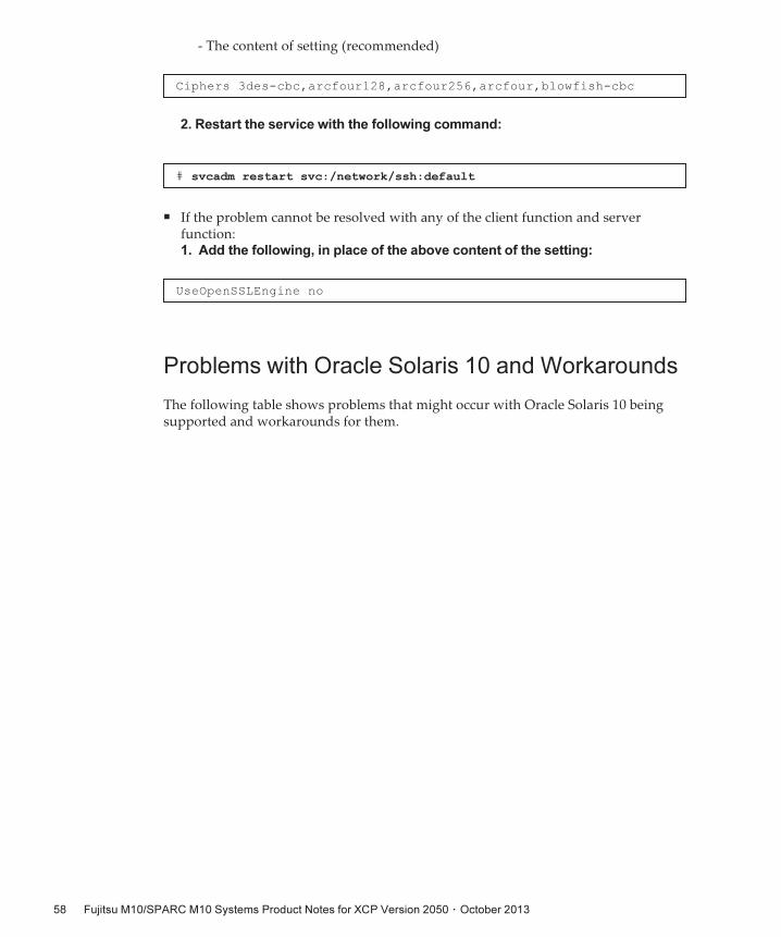
Ciphers 3des-cbc,arcfour128,arcfour256,arcfour,blowfish-cbc
# svcadm restart svc:/network/ssh:default
UseOpenSSLEngine no
- The content of setting (recommended)
2. Restart the service with the following command:
■ If the problem cannot be resolved with any of the client function and serverfunction:1. Add the following, in place of the above content of the setting:
Problems with Oracle Solaris 10 and Workarounds
The following table shows problems that might occur with Oracle Solaris 10 beingsupported and workarounds for them.
Fujitsu M10/SPARC M10 Systems Product Notes for XCP Version 2050 ・ October 201358
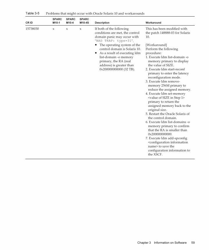
Table 3-5 Problems that might occur with Oracle Solaris 10 and workarounds
CR ID
SPARC
M10-1
SPARC
M10-4
SPARC
M10-4S Description Workaround
15738030 x x x If both of the followingconditions are met, the controldomain panic may occur with"BAD TRAP: type=31".■ The operating system of the
control domain is Solaris 10.■ As a result of executing ldm
list-domain -o memoryprimary, the RA (realaddress) is greater than0x200000000000 (32 TB).
This has been modified withthe patch 148888-03 for Solaris10.
[Workaround]Perform the followingprocedure:1. Execute ldm list-domain -o
memory primary to displaythe value of SIZE.
2. Execute ldm start-reconfprimary to enter the latencyreconfiguration mode.
3. Execute ldm remove-memory 256M primary toreduce the assigned memory.
4. Execute ldm set-memory<value of SIZE in Step 1>primary to return theassigned memory back to theoriginal size.
5. Restart the Oracle Solaris ofthe control domain.
6. Execute ldm list-domains -omemory primary to confirmthat the RA is smaller than0x200000000000.
7. Execute ldm add-spconfig<configuration informationname> to save theconfiguration information tothe XSCF.
Chapter 3 Information on Software 59

Fujitsu M10/SPARC M10 Systems Product Notes for XCP Version 2050 ・ October 201360
Chapter 4
Information on SPARC M10-1Hardware
This chapter describes special instructions and problems concerning the SPARCM10-1 hardware.■ Notes and Restrictions
■ Device Paths of SPARC M10-1
■ Problems with Hardware and Workarounds
Notes and Restrictions
Notes on using external DVD drive
USB bus power drive is not supported for external DVD drives connected via USB.
Notes on using USB memory
Prepare a USB memory as a medium in advance if you execute the commandspecifying the USB memory as a destination of saving data, among XSCF commands.The saved data contains information on the system . If you use the USB memory,consideration should be made for the management of the USB memory in which thedata is saved, for security reasons.Not all the commercially available USB memories of any manufacturer areguaranteed for their connectivity and operability with XSCF. Abnormalities mayoccur such as an XSCF firmware error or reset depending on your USB memories. Insuch a case, immediately stop using the USB memory.When connecting a USB memory to the USB port for XSCF, directly connect it to theUSB port. If you connect the USB memory via the USB hub or USB extension cable, itmay cause an error.
61

Table 4-1 The guideline for synchronization time of hardware RAID
RAID Number of disk drives Synchronization time
1 2 90 minutes
Notes on hardware RAID
There are the following precautions when you use hardware RAID.
Notes when using hardware RAID
■ Perform backup of important data and programs on a regular basis. For someerrors, you may need to restore data or programs from a backup media byreconstructing the hardware RAID.
■ We recommend using an uninterruptible power supply (UPS) in order to securethe data in the system in case of power outage.
■ If a high availability such as duplication of the controller or data path is requiredfor the hardware RAID function, install a dedicated RAID system.
About hardware RAID management utility
■ When you use the hardware RAID function of a SPARC M10 system, werecommend using the RAID management utility (sas2ircu: SAS2 Integrated RAIDConfiguration Utility) provided by the LSI Corporation, in order to manage thehardware RAID environment. In the OpenBoot PROM environment, you can setthe hardware RAID but cannot manage it.
■ For details on how to obtain the RAID management utility, see the LSI Corporationwebsite described in "12.2 Configuring Hardware RAID" in SPARC M10 SystemsSystem Operation and Administration Guide. For details on how to use this, see SAS2Integrated RAID Solution User Guide on the same website.
■ If the RAID volume fails, you can specify the failed disk by using the RAIDmanagement utility.
■ The RAID management utility is used in the Oracle Solaris OS environmentlogged in with an account with root privilege. Therefore, the RAID managementutility should be operated by a system administrator.
Notes when configuring/removing hardware RAID
■ When configuring/removing the hardware RAID, preserving data on a disk is notguaranteed. Be sure to perform backup of data when you initially configure thehardware RAID to the system that is in operation or remove an installed hardwareRAID. After configuring the hardware RAID, you need to newly install data orrestore data from a backup media.
■ The following table shows a guideline for synchronization time associated withhardware RAID configuration or maintenance for 600 GB HDD with unloadedcondition.
Fujitsu M10/SPARC M10 Systems Product Notes for XCP Version 2050 ・ October 201362
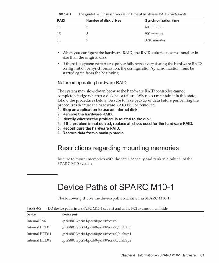
Table 4-1 The guideline for synchronization time of hardware RAID (continued)
RAID Number of disk drives Synchronization time
1E 3 600 minutes
1E 5 900 minutes
1E 7 3240 minutes
Table 4-2 I/O device paths in a SPARC M10-1 cabinet and at the PCI expansion unit side
Device Device path
Internal SAS /pci@8000/pci@4/pci@0/pci@0/scsi@0
Internal HDD#0 /pci@8000/pci@4/pci@0/pci@0/scsi@0/disk@p0
Internal HDD#1 /pci@8000/pci@4/pci@0/pci@0/scsi@0/disk@p1
Internal HDD#2 /pci@8000/pci@4/pci@0/pci@0/scsi@0/disk@p2
■ When you configure the hardware RAID, the RAID volume becomes smaller insize than the original disk.
■ If there is a system restart or a power failure/recovery during the hardware RAIDconfiguration or synchronization, the configuration/synchronization must bestarted again from the beginning.
Notes on operating hardware RAID
The system may slow down because the hardware RAID controller cannotcompletely judge whether a disk has a failure. When you maintain it in this state,follow the procedures below. Be sure to take backup of data before performing theprocedures because the hardware RAID will be removed.1. Stop an application to use an internal disk.
2. Remove the hardware RAID.
3. Identify whether the problem is related to the disk.
4. If the problem is not solved, replace all disks used for the hardware RAID.
5. Reconfigure the hardware RAID.
6. Restore data from a backup media.
Restrictions regarding mounting memories
Be sure to mount memories with the same capacity and rank in a cabinet of theSPARC M10 system.
Device Paths of SPARC M10-1The following shows the device paths identified in SPARC M10-1.
Chapter 4 Information on SPARC M10-1 Hardware 63
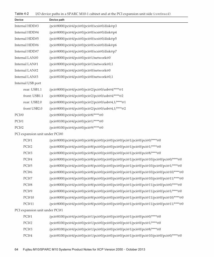
Table 4-2 I/O device paths in a SPARC M10-1 cabinet and at the PCI expansion unit side (continued)
Device Device path
Internal HDD#3 /pci@8000/pci@4/pci@0/pci@0/scsi@0/disk@p3
Internal HDD#4 /pci@8000/pci@4/pci@0/pci@0/scsi@0/disk@p4
Internal HDD#5 /pci@8000/pci@4/pci@0/pci@0/scsi@0/disk@p5
Internal HDD#6 /pci@8000/pci@4/pci@0/pci@0/scsi@0/disk@p6
Internal HDD#7 /pci@8000/pci@4/pci@0/pci@0/scsi@0/disk@p7
Internal LAN#0 /pci@8000/pci@4/pci@0/pci@1/network@0
Internal LAN#1 /pci@8000/pci@4/pci@0/pci@1/network@0,1
Internal LAN#2 /pci@8100/pci@4/pci@0/pci@0/network@0
Internal LAN#3 /pci@8100/pci@4/pci@0/pci@0/network@0,1
Internal USB port
rear: USB1.1 /pci@8000/pci@4/pci@0/pci@2/pci@0/usb@4/****@1
front: USB1.1 /pci@8000/pci@4/pci@0/pci@2/pci@0/usb@4/****@2
rear: USB2.0 /pci@8000/pci@4/pci@0/pci@2/pci@0/usb@4,1/****@1
front USB2.0 /pci@8000/pci@4/pci@0/pci@2/pci@0/usb@4,1/****@2
PCI#0 /pci@8000/pci@4/pci@0/pci@8/****@0
PCI#1 /pci@8100/pci@4/pci@0/pci@1/****@0
PCI#2 /pci@8100/pci@4/pci@0/pci@9/****@0
PCI expansion unit under PCI#0
PCI#1 /pci@8000/pci@4/pci@0/pci@8/pci@0/pci@0/pci@0/pci@1/pci@0/pci@0/****@0
PCI#2 /pci@8000/pci@4/pci@0/pci@8/pci@0/pci@0/pci@0/pci@1/pci@0/pci@1/****@0
PCI#3 /pci@8000/pci@4/pci@0/pci@8/pci@0/pci@0/pci@0/pci@1/pci@0/pci@8/****@0
PCI#4 /pci@8000/pci@4/pci@0/pci@8/pci@0/pci@0/pci@0/pci@1/pci@0/pci@10/pci@0/pci@0/****@0
PCI#5 /pci@8000/pci@4/pci@0/pci@8/pci@0/pci@0/pci@0/pci@1/pci@0/pci@10/pci@0/pci@1/****@0
PCI#6 /pci@8000/pci@4/pci@0/pci@8/pci@0/pci@0/pci@0/pci@1/pci@0/pci@10/pci@0/pci@10/****@0
PCI#7 /pci@8000/pci@4/pci@0/pci@8/pci@0/pci@0/pci@0/pci@1/pci@0/pci@10/pci@0/pci@11/****@0
PCI#8 /pci@8000/pci@4/pci@0/pci@8/pci@0/pci@0/pci@0/pci@1/pci@0/pci@11/pci@0/pci@0/****@0
PCI#9 /pci@8000/pci@4/pci@0/pci@8/pci@0/pci@0/pci@0/pci@1/pci@0/pci@11/pci@0/pci@1/****@0
PCI#10 /pci@8000/pci@4/pci@0/pci@8/pci@0/pci@0/pci@0/pci@1/pci@0/pci@11/pci@0/pci@10/****@0
PCI#11 /pci@8000/pci@4/pci@0/pci@8/pci@0/pci@0/pci@0/pci@1/pci@0/pci@11/pci@0/pci@11/****@0
PCI expansion unit under PCI#1
PCI#1 /pci@8100/pci@4/pci@0/pci@1/pci@0/pci@0/pci@0/pci@1/pci@0/pci@0/****@0
PCI#2 /pci@8100/pci@4/pci@0/pci@1/pci@0/pci@0/pci@0/pci@1/pci@0/pci@1/****@0
PCI#3 /pci@8100/pci@4/pci@0/pci@1/pci@0/pci@0/pci@0/pci@1/pci@0/pci@8/****@0
PCI#4 /pci@8100/pci@4/pci@0/pci@1/pci@0/pci@0/pci@0/pci@1/pci@0/pci@10/pci@0/pci@0/****@0
Fujitsu M10/SPARC M10 Systems Product Notes for XCP Version 2050 ・ October 201364
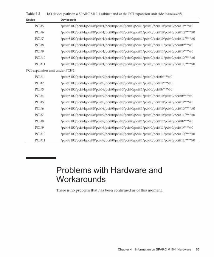
Table 4-2 I/O device paths in a SPARC M10-1 cabinet and at the PCI expansion unit side (continued)
Device Device path
PCI#5 /pci@8100/pci@4/pci@0/pci@1/pci@0/pci@0/pci@0/pci@1/pci@0/pci@10/pci@0/pci@1/****@0
PCI#6 /pci@8100/pci@4/pci@0/pci@1/pci@0/pci@0/pci@0/pci@1/pci@0/pci@10/pci@0/pci@10/****@0
PCI#7 /pci@8100/pci@4/pci@0/pci@1/pci@0/pci@0/pci@0/pci@1/pci@0/pci@10/pci@0/pci@11/****@0
PCI#8 /pci@8100/pci@4/pci@0/pci@1/pci@0/pci@0/pci@0/pci@1/pci@0/pci@11/pci@0/pci@0/****@0
PCI#9 /pci@8100/pci@4/pci@0/pci@1/pci@0/pci@0/pci@0/pci@1/pci@0/pci@11/pci@0/pci@1/****@0
PCI#10 /pci@8100/pci@4/pci@0/pci@1/pci@0/pci@0/pci@0/pci@1/pci@0/pci@11/pci@0/pci@10/****@0
PCI#11 /pci@8100/pci@4/pci@0/pci@1/pci@0/pci@0/pci@0/pci@1/pci@0/pci@11/pci@0/pci@11/****@0
PCI expansion unit under PCI#2
PCI#1 /pci@8100/pci@4/pci@0/pci@9/pci@0/pci@0/pci@0/pci@1/pci@0/pci@0/****@0
PCI#2 /pci@8100/pci@4/pci@0/pci@9/pci@0/pci@0/pci@0/pci@1/pci@0/pci@1/****@0
PCI#3 /pci@8100/pci@4/pci@0/pci@9/pci@0/pci@0/pci@0/pci@1/pci@0/pci@8/****@0
PCI#4 /pci@8100/pci@4/pci@0/pci@9/pci@0/pci@0/pci@0/pci@1/pci@0/pci@10/pci@0/pci@0/****@0
PCI#5 /pci@8100/pci@4/pci@0/pci@9/pci@0/pci@0/pci@0/pci@1/pci@0/pci@10/pci@0/pci@1/****@0
PCI#6 /pci@8100/pci@4/pci@0/pci@9/pci@0/pci@0/pci@0/pci@1/pci@0/pci@10/pci@0/pci@10/****@0
PCI#7 /pci@8100/pci@4/pci@0/pci@9/pci@0/pci@0/pci@0/pci@1/pci@0/pci@10/pci@0/pci@11/****@0
PCI#8 /pci@8100/pci@4/pci@0/pci@9/pci@0/pci@0/pci@0/pci@1/pci@0/pci@11/pci@0/pci@0/****@0
PCI#9 /pci@8100/pci@4/pci@0/pci@9/pci@0/pci@0/pci@0/pci@1/pci@0/pci@11/pci@0/pci@1/****@0
PCI#10 /pci@8100/pci@4/pci@0/pci@9/pci@0/pci@0/pci@0/pci@1/pci@0/pci@11/pci@0/pci@10/****@0
PCI#11 /pci@8100/pci@4/pci@0/pci@9/pci@0/pci@0/pci@0/pci@1/pci@0/pci@11/pci@0/pci@11/****@0
Problems with Hardware andWorkaroundsThere is no problem that has been confirmed as of this moment.
Chapter 4 Information on SPARC M10-1 Hardware 65

Fujitsu M10/SPARC M10 Systems Product Notes for XCP Version 2050 ・ October 201366

Chapter 5
Information on SPARC M10-4Hardware
This chapter describes special instructions and problems concerning the SPARCM10-4 hardware.■ Notes and Restrictions
■ Device Paths of SPARC M10-4
■ Problems with Hardware and Workarounds
Notes and Restrictions
Notes on using external DVD drive
USB bus power drive is not supported for external DVD drives connected via USB.
Notes on using USB memory
Prepare a USB memory as a medium in advance if you execute the commandspecifying the USB memory as a destination of saving data, among XSCF commands.The saved data contains information on the system . If you use the USB memory,consideration should be made for the management of the USB memory in which thedata is saved, for security reasons.Not all the commercially available USB memories of any manufacturer areguaranteed for their connectivity and operability with XSCF. Abnormalities mayoccur such as an XSCF firmware error or reset depending on your USB memories. Insuch a case, immediately stop using the USB memory.When connecting a USB memory to the USB port for XSCF, directly connect it to theUSB port. If you connect the USB memory via the USB hub or USB extension cable, itmay cause an error.
67
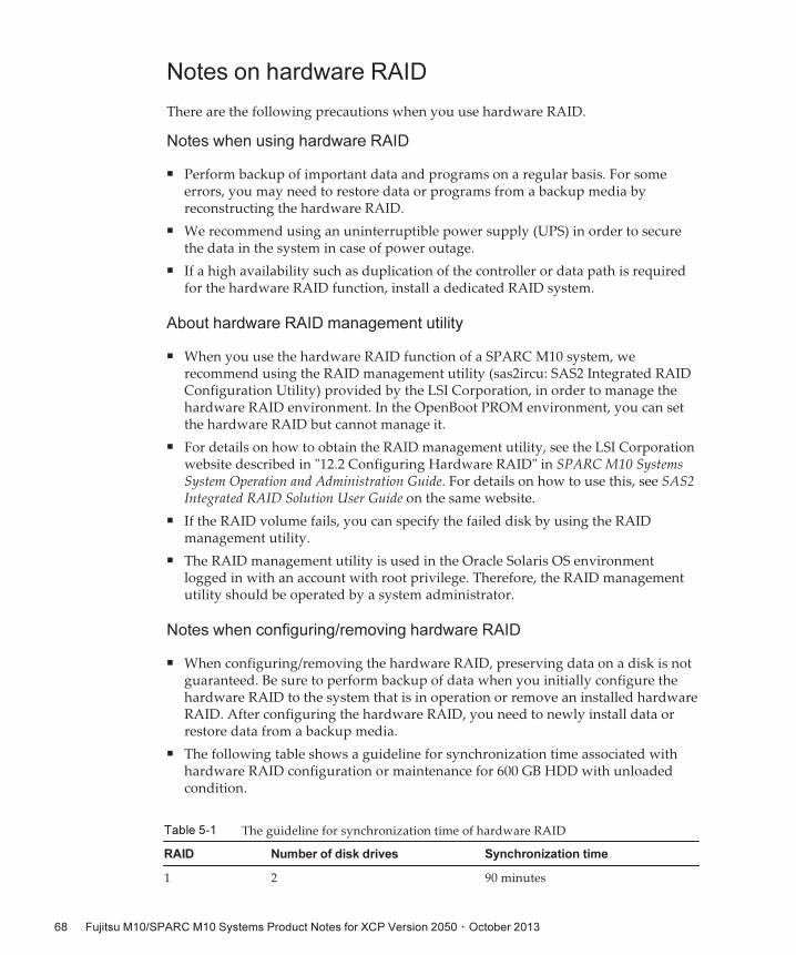
Table 5-1 The guideline for synchronization time of hardware RAID
RAID Number of disk drives Synchronization time
1 2 90 minutes
Notes on hardware RAID
There are the following precautions when you use hardware RAID.
Notes when using hardware RAID
■ Perform backup of important data and programs on a regular basis. For someerrors, you may need to restore data or programs from a backup media byreconstructing the hardware RAID.
■ We recommend using an uninterruptible power supply (UPS) in order to securethe data in the system in case of power outage.
■ If a high availability such as duplication of the controller or data path is requiredfor the hardware RAID function, install a dedicated RAID system.
About hardware RAID management utility
■ When you use the hardware RAID function of a SPARC M10 system, werecommend using the RAID management utility (sas2ircu: SAS2 Integrated RAIDConfiguration Utility) provided by the LSI Corporation, in order to manage thehardware RAID environment. In the OpenBoot PROM environment, you can setthe hardware RAID but cannot manage it.
■ For details on how to obtain the RAID management utility, see the LSI Corporationwebsite described in "12.2 Configuring Hardware RAID" in SPARC M10 SystemsSystem Operation and Administration Guide. For details on how to use this, see SAS2Integrated RAID Solution User Guide on the same website.
■ If the RAID volume fails, you can specify the failed disk by using the RAIDmanagement utility.
■ The RAID management utility is used in the Oracle Solaris OS environmentlogged in with an account with root privilege. Therefore, the RAID managementutility should be operated by a system administrator.
Notes when configuring/removing hardware RAID
■ When configuring/removing the hardware RAID, preserving data on a disk is notguaranteed. Be sure to perform backup of data when you initially configure thehardware RAID to the system that is in operation or remove an installed hardwareRAID. After configuring the hardware RAID, you need to newly install data orrestore data from a backup media.
■ The following table shows a guideline for synchronization time associated withhardware RAID configuration or maintenance for 600 GB HDD with unloadedcondition.
Fujitsu M10/SPARC M10 Systems Product Notes for XCP Version 2050 ・ October 201368
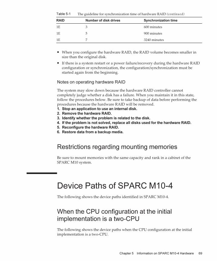
Table 5-1 The guideline for synchronization time of hardware RAID (continued)
RAID Number of disk drives Synchronization time
1E 3 600 minutes
1E 5 900 minutes
1E 7 3240 minutes
■ When you configure the hardware RAID, the RAID volume becomes smaller insize than the original disk.
■ If there is a system restart or a power failure/recovery during the hardware RAIDconfiguration or synchronization, the configuration/synchronization must bestarted again from the beginning.
Notes on operating hardware RAID
The system may slow down because the hardware RAID controller cannotcompletely judge whether a disk has a failure. When you maintain it in this state,follow the procedures below. Be sure to take backup of data before performing theprocedures because the hardware RAID will be removed.1. Stop an application to use an internal disk.
2. Remove the hardware RAID.
3. Identify whether the problem is related to the disk.
4. If the problem is not solved, replace all disks used for the hardware RAID.
5. Reconfigure the hardware RAID.
6. Restore data from a backup media.
Restrictions regarding mounting memories
Be sure to mount memories with the same capacity and rank in a cabinet of theSPARC M10 system.
Device Paths of SPARC M10-4The following shows the device paths identified in SPARC M10-4.
When the CPU configuration at the initialimplementation is a two-CPU
The following shows the device paths when the CPU configuration at the initialimplementation is a two-CPU.
Chapter 5 Information on SPARC M10-4 Hardware 69
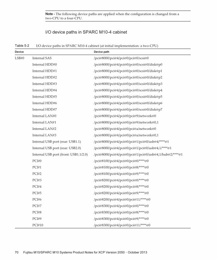
Note - The following device paths are applied when the configuration is changed from atwo-CPU to a four-CPU.
Table 5-2 I/O device paths in SPARC M10-4 cabinet (at initial implementation: a two-CPU)
Device Device path
LSB#0 Internal SAS /pci@8000/pci@4/pci@0/pci@0/scsi@0
Internal HDD#0 /pci@8000/pci@4/pci@0/pci@0/scsi@0/disk@p0
Internal HDD#1 /pci@8000/pci@4/pci@0/pci@0/scsi@0/disk@p1
Internal HDD#2 /pci@8000/pci@4/pci@0/pci@0/scsi@0/disk@p2
Internal HDD#3 /pci@8000/pci@4/pci@0/pci@0/scsi@0/disk@p3
Internal HDD#4 /pci@8000/pci@4/pci@0/pci@0/scsi@0/disk@p4
Internal HDD#5 /pci@8000/pci@4/pci@0/pci@0/scsi@0/disk@p5
Internal HDD#6 /pci@8000/pci@4/pci@0/pci@0/scsi@0/disk@p6
Internal HDD#7 /pci@8000/pci@4/pci@0/pci@0/scsi@0/disk@p7
Internal LAN#0 /pci@8000/pci@4/pci@0/pci@9/network@0
Internal LAN#1 /pci@8000/pci@4/pci@0/pci@9/network@0,1
Internal LAN#2 /pci@8000/pci@4/pci@0/pci@a/network@0
Internal LAN#3 /pci@8000/pci@4/pci@0/pci@a/network@0,1
Internal USB port (rear: USB1.1) /pci@8000/pci@4/pci@0/pci@1/pci@0/usb@4/****@1
Internal USB port (rear: USB2.0) /pci@8000/pci@4/pci@0/pci@1/pci@0/usb@4,1/****@1
Internal USB port (front: USB1.1/2.0) /pci@8000/pci@4/pci@0/pci@1/pci@0/usb@4,1/hub@2/****@1
PCI#0 /pci@8100/pci@4/pci@0/pci@0/****@0
PCI#1 /pci@8100/pci@4/pci@0/pci@8/****@0
PCI#2 /pci@8100/pci@4/pci@0/pci@9/****@0
PCI#3 /pci@8200/pci@4/pci@0/pci@0/****@0
PCI#4 /pci@8200/pci@4/pci@0/pci@8/****@0
PCI#5 /pci@8200/pci@4/pci@0/pci@9/****@0
PCI#6 /pci@8200/pci@4/pci@0/pci@11/****@0
PCI#7 /pci@8300/pci@4/pci@0/pci@0/****@0
PCI#8 /pci@8300/pci@4/pci@0/pci@8/****@0
PCI#9 /pci@8300/pci@4/pci@0/pci@9/****@0
PCI#10 /pci@8300/pci@4/pci@0/pci@11/****@0
I/O device paths in SPARC M10-4 cabinet
Fujitsu M10/SPARC M10 Systems Product Notes for XCP Version 2050 ・ October 201370
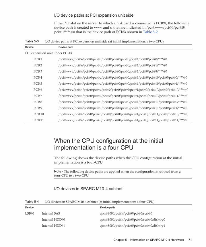
Table 5-3 I/O device paths at PCI expansion unit side (at initial implementation: a two-CPU)
Device Device path
PCI expansion unit under PCI#X
PCI#1 /pci@vvvv/pci@4/pci@0/pci@u/pci@0/pci@0/pci@0/pci@1/pci@0/pci@0/****@0
PCI#2 /pci@vvvv/pci@4/pci@0/pci@u/pci@0/pci@0/pci@0/pci@1/pci@0/pci@1/****@0
PCI#3 /pci@vvvv/pci@4/pci@0/pci@u/pci@0/pci@0/pci@0/pci@1/pci@0/pci@8/****@0
PCI#4 /pci@vvvv/pci@4/pci@0/pci@u/pci@0/pci@0/pci@0/pci@1/pci@0/pci@10/pci@0/pci@0/****@0
PCI#5 /pci@vvvv/pci@4/pci@0/pci@u/pci@0/pci@0/pci@0/pci@1/pci@0/pci@10/pci@0/pci@1/****@0
PCI#6 /pci@vvvv/pci@4/pci@0/pci@u/pci@0/pci@0/pci@0/pci@1/pci@0/pci@10/pci@0/pci@10/****@0
PCI#7 /pci@vvvv/pci@4/pci@0/pci@u/pci@0/pci@0/pci@0/pci@1/pci@0/pci@10/pci@0/pci@11/****@0
PCI#8 /pci@vvvv/pci@4/pci@0/pci@u/pci@0/pci@0/pci@0/pci@1/pci@0/pci@11/pci@0/pci@0/****@0
PCI#9 /pci@vvvv/pci@4/pci@0/pci@u/pci@0/pci@0/pci@0/pci@1/pci@0/pci@11/pci@0/pci@1/****@0
PCI#10 /pci@vvvv/pci@4/pci@0/pci@u/pci@0/pci@0/pci@0/pci@1/pci@0/pci@11/pci@0/pci@10/****@0
PCI#11 /pci@vvvv/pci@4/pci@0/pci@u/pci@0/pci@0/pci@0/pci@1/pci@0/pci@11/pci@0/pci@11/****@0
Note - The following device paths are applied when the configuration is reduced from afour-CPU to a two-CPU.
Table 5-4 I/O devices in SPARC M10-4 cabinet (at initial implementation: a four-CPU)
Device Device path
LSB#0 Internal SAS /pci@8000/pci@4/pci@0/pci@0/scsi@0
Internal HDD#0 /pci@8000/pci@4/pci@0/pci@0/scsi@0/disk@p0
Internal HDD#1 /pci@8000/pci@4/pci@0/pci@0/scsi@0/disk@p1
I/O device paths at PCI expansion unit side
If the PCI slot on the server to which a link card is connected is PCI#X, the followingdevice path is created to vvvv and u that are indicated in /pci@vvvv/pci@4/pci@0/pci@u/****@0 that is the device path of PCI#X shown in Table 5-2.
When the CPU configuration at the initialimplementation is a four-CPU
The following shows the device paths when the CPU configuration at the initialimplementation is a four-CPU
I/O devices in SPARC M10-4 cabinet
Chapter 5 Information on SPARC M10-4 Hardware 71
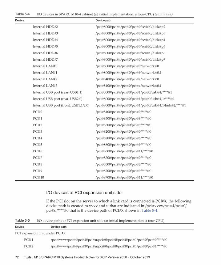
Table 5-4 I/O devices in SPARC M10-4 cabinet (at initial implementation: a four-CPU) (continued)
Device Device path
Internal HDD#2 /pci@8000/pci@4/pci@0/pci@0/scsi@0/disk@p2
Internal HDD#3 /pci@8000/pci@4/pci@0/pci@0/scsi@0/disk@p3
Internal HDD#4 /pci@8000/pci@4/pci@0/pci@0/scsi@0/disk@p4
Internal HDD#5 /pci@8000/pci@4/pci@0/pci@0/scsi@0/disk@p5
Internal HDD#6 /pci@8000/pci@4/pci@0/pci@0/scsi@0/disk@p6
Internal HDD#7 /pci@8000/pci@4/pci@0/pci@0/scsi@0/disk@p7
Internal LAN#0 /pci@8000/pci@4/pci@0/pci@9/network@0
Internal LAN#1 /pci@8000/pci@4/pci@0/pci@9/network@0,1
Internal LAN#2 /pci@8400/pci@4/pci@0/pci@a/network@0
Internal LAN#3 /pci@8400/pci@4/pci@0/pci@a/network@0,1
Internal USB port (rear: USB1.1) /pci@8000/pci@4/pci@0/pci@1/pci@0/usb@4/****@1
Internal USB port (rear: USB2.0) /pci@8000/pci@4/pci@0/pci@1/pci@0/usb@4,1/****@1
Internal USB port (front: USB1.1/2.0) /pci@8000/pci@4/pci@0/pci@1/pci@0/usb@4,1/hub@2/****@1
PCI#0 /pci@8100/pci@4/pci@0/pci@0/****@0
PCI#1 /pci@8500/pci@4/pci@0/pci@8/****@0
PCI#2 /pci@8500/pci@4/pci@0/pci@9/****@0
PCI#3 /pci@8200/pci@4/pci@0/pci@0/****@0
PCI#4 /pci@8200/pci@4/pci@0/pci@8/****@0
PCI#5 /pci@8600/pci@4/pci@0/pci@9/****@0
PCI#6 /pci@8600/pci@4/pci@0/pci@11/****@0
PCI#7 /pci@8300/pci@4/pci@0/pci@0/****@0
PCI#8 /pci@8300/pci@4/pci@0/pci@8/****@0
PCI#9 /pci@8700/pci@4/pci@0/pci@9/****@0
PCI#10 /pci@8700/pci@4/pci@0/pci@11/****@0
Table 5-5 I/O device paths at PCI expansion unit side (at initial implementation: a four-CPU)
Device Device path
PCI expansion unit under PCI#X
PCI#1 /pci@vvvv/pci@4/pci@0/pci@u/pci@0/pci@0/pci@0/pci@1/pci@0/pci@0/****@0
PCI#2 /pci@vvvv/pci@4/pci@0/pci@u/pci@0/pci@0/pci@0/pci@1/pci@0/pci@1/****@0
I/O devices at PCI expansion unit side
If the PCI slot on the server to which a link card is connected is PCI#X, the followingdevice path is created to vvvv and u that are indicated in /pci@vvvv/pci@4/pci@0/pci@u/****@0 that is the device path of PCI#X shown in Table 5-4.
Fujitsu M10/SPARC M10 Systems Product Notes for XCP Version 2050 ・ October 201372
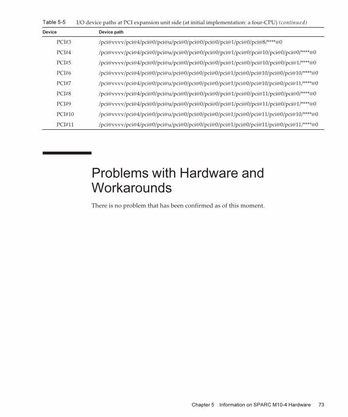
Table 5-5 I/O device paths at PCI expansion unit side (at initial implementation: a four-CPU) (continued)
Device Device path
PCI#3 /pci@vvvv/pci@4/pci@0/pci@u/pci@0/pci@0/pci@0/pci@1/pci@0/pci@8/****@0
PCI#4 /pci@vvvv/pci@4/pci@0/pci@u/pci@0/pci@0/pci@0/pci@1/pci@0/pci@10/pci@0/pci@0/****@0
PCI#5 /pci@vvvv/pci@4/pci@0/pci@u/pci@0/pci@0/pci@0/pci@1/pci@0/pci@10/pci@0/pci@1/****@0
PCI#6 /pci@vvvv/pci@4/pci@0/pci@u/pci@0/pci@0/pci@0/pci@1/pci@0/pci@10/pci@0/pci@10/****@0
PCI#7 /pci@vvvv/pci@4/pci@0/pci@u/pci@0/pci@0/pci@0/pci@1/pci@0/pci@10/pci@0/pci@11/****@0
PCI#8 /pci@vvvv/pci@4/pci@0/pci@u/pci@0/pci@0/pci@0/pci@1/pci@0/pci@11/pci@0/pci@0/****@0
PCI#9 /pci@vvvv/pci@4/pci@0/pci@u/pci@0/pci@0/pci@0/pci@1/pci@0/pci@11/pci@0/pci@1/****@0
PCI#10 /pci@vvvv/pci@4/pci@0/pci@u/pci@0/pci@0/pci@0/pci@1/pci@0/pci@11/pci@0/pci@10/****@0
PCI#11 /pci@vvvv/pci@4/pci@0/pci@u/pci@0/pci@0/pci@0/pci@1/pci@0/pci@11/pci@0/pci@11/****@0
Problems with Hardware andWorkaroundsThere is no problem that has been confirmed as of this moment.
Chapter 5 Information on SPARC M10-4 Hardware 73

Fujitsu M10/SPARC M10 Systems Product Notes for XCP Version 2050 ・ October 201374
Chapter 6
Information on SPARC M10-4SHardware
This chapter describes special instructions and problems concerning the SPARCM10-4S hardware.■ Notes and Restrictions
■ Device Paths of SPARC M10-4S
■ Problems with Hardware and Workarounds
Notes and Restrictions
Notes on using external DVD drive
USB bus power drive is not supported for external DVD drives connected via USB.
Notes on using USB memory
Prepare a USB memory as a medium in advance if you execute the commandspecifying the USB memory as a destination of saving data, among XSCF commands.The saved data contains information on the system . If you use the USB memory,consideration should be made for the management of the USB memory in which thedata is saved, for security reasons.Not all the commercially available USB memories of any manufacturer areguaranteed for their connectivity and operability with XSCF. Abnormalities mayoccur such as an XSCF firmware error or reset depending on your USB memories. Insuch a case, immediately stop using the USB memory.When connecting a USB memory to the USB port for XSCF, directly connect it to theUSB port. If you connect the USB memory via the USB hub or USB extension cable, itmay cause an error.
75

Table 6-1 The guideline for synchronization time of hardware RAID
RAID Number of disk drives Synchronization time
1 2 90 minutes
Notes on hardware RAID
There are the following precautions when you use hardware RAID.
Notes when using hardware RAID
■ Perform backup of important data and programs on a regular basis. For someerrors, you may need to restore data or programs from a backup media byreconstructing the hardware RAID.
■ We recommend using an uninterruptible power supply (UPS) in order to securethe data in the system in case of power outage.
■ If a high availability such as duplication of the controller or data path is requiredfor the hardware RAID function, install a dedicated RAID system.
About hardware RAID management utility
■ When you use the hardware RAID function of a SPARC M10 system, werecommend using the RAID management utility (sas2ircu: SAS2 Integrated RAIDConfiguration Utility) provided by the LSI Corporation, in order to manage thehardware RAID environment. In the OpenBoot PROM environment, you can setthe hardware RAID but cannot manage it.
■ For details on how to obtain the RAID management utility, see the LSI Corporationwebsite described in "12.2 Configuring Hardware RAID" in SPARC M10 SystemsSystem Operation and Administration Guide. For details on how to use this, see SAS2Integrated RAID Solution User Guide on the same website.
■ If the RAID volume fails, you can specify the failed disk by using the RAIDmanagement utility.
■ The RAID management utility is used in the Oracle Solaris OS environmentlogged in with an account with root privilege. Therefore, the RAID managementutility should be operated by a system administrator.
Notes when configuring/removing hardware RAID
■ When configuring/removing the hardware RAID, preserving data on a disk is notguaranteed. Be sure to perform backup of data when you initially configure thehardware RAID to the system that is in operation or remove an installed hardwareRAID. After configuring the hardware RAID, you need to newly install data orrestore data from a backup media.
■ The following table shows a guideline for synchronization time associated withhardware RAID configuration or maintenance for 600 GB HDD with unloadedcondition.
Fujitsu M10/SPARC M10 Systems Product Notes for XCP Version 2050 ・ October 201376
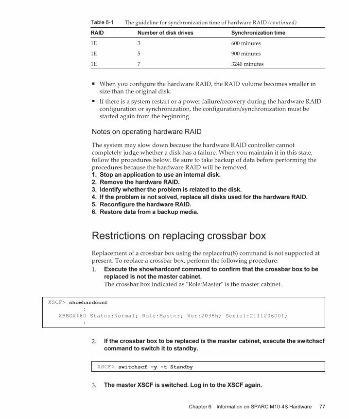
Table 6-1 The guideline for synchronization time of hardware RAID (continued)
RAID Number of disk drives Synchronization time
1E 3 600 minutes
1E 5 900 minutes
1E 7 3240 minutes
XSCF> showhardconf:
XBBOX#80 Status:Normal; Role:Master; Ver:2038h; Serial:2111206001;
:
XSCF> switchscf -y -t Standby
■ When you configure the hardware RAID, the RAID volume becomes smaller insize than the original disk.
■ If there is a system restart or a power failure/recovery during the hardware RAIDconfiguration or synchronization, the configuration/synchronization must bestarted again from the beginning.
Notes on operating hardware RAID
The system may slow down because the hardware RAID controller cannotcompletely judge whether a disk has a failure. When you maintain it in this state,follow the procedures below. Be sure to take backup of data before performing theprocedures because the hardware RAID will be removed.1. Stop an application to use an internal disk.
2. Remove the hardware RAID.
3. Identify whether the problem is related to the disk.
4. If the problem is not solved, replace all disks used for the hardware RAID.
5. Reconfigure the hardware RAID.
6. Restore data from a backup media.
Restrictions on replacing crossbar box
Replacement of a crossbar box using the replacefru(8) command is not supported atpresent. To replace a crossbar box, perform the following procedure:
1. Execute the showhardconf command to confirm that the crossbar box to be
replaced is not the master cabinet.
The crossbar box indicated as "Role:Master" is the master cabinet.
2. If the crossbar box to be replaced is the master cabinet, execute the switchscf
command to switch it to standby.
3. The master XSCF is switched. Log in to the XSCF again.
Chapter 6 Information on SPARC M10-4S Hardware 77
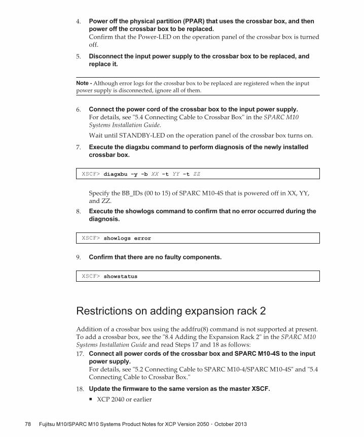
Note - Although error logs for the crossbar box to be replaced are registered when the inputpower supply is disconnected, ignore all of them.
XSCF> diagxbu -y -b XX -t YY -t ZZ
XSCF> showlogs error
XSCF> showstatus
4. Power off the physical partition (PPAR) that uses the crossbar box, and then
power off the crossbar box to be replaced.
Confirm that the Power-LED on the operation panel of the crossbar box is turnedoff.
5. Disconnect the input power supply to the crossbar box to be replaced, and
replace it.
6. Connect the power cord of the crossbar box to the input power supply.
For details, see "5.4 Connecting Cable to Crossbar Box" in the SPARC M10Systems Installation Guide.
Wait until STANDBY-LED on the operation panel of the crossbar box turns on.
7. Execute the diagxbu command to perform diagnosis of the newly installed
crossbar box.
Specify the BB_IDs (00 to 15) of SPARC M10-4S that is powered off in XX, YY,and ZZ.
8. Execute the showlogs command to confirm that no error occurred during the
diagnosis.
9. Confirm that there are no faulty components.
Restrictions on adding expansion rack 2
Addition of a crossbar box using the addfru(8) command is not supported at present.To add a crossbar box, see the "8.4 Adding the Expansion Rack 2" in the SPARC M10Systems Installation Guide and read Steps 17 and 18 as follows:
17. Connect all power cords of the crossbar box and SPARC M10-4S to the input
power supply.
For details, see "5.2 Connecting Cable to SPARC M10-4/SPARC M10-4S" and "5.4Connecting Cable to Crossbar Box."
18. Update the firmware to the same version as the master XSCF.
■ XCP 2040 or earlier
Fujitsu M10/SPARC M10 Systems Product Notes for XCP Version 2050 ・ October 201378
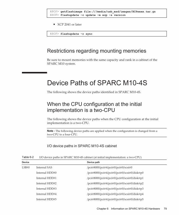
XSCF> getflashimage file:///media/usb_msd/images/XCPxxxx.tar.gzXSCF> flashupdate -c update -m xcp -s version
XSCF> flashupdate -c sync
Note - The following device paths are applied when the configuration is changed from atwo-CPU to a four-CPU.
Table 6-2 I/O device paths in SPARC M10-4S cabinet (at initial implementation: a two-CPU)
Device Device path
LSB#0 Internal SAS /pci@8000/pci@4/pci@0/pci@0/scsi@0
Internal HDD#0 /pci@8000/pci@4/pci@0/pci@0/scsi@0/disk@p0
Internal HDD#1 /pci@8000/pci@4/pci@0/pci@0/scsi@0/disk@p1
Internal HDD#2 /pci@8000/pci@4/pci@0/pci@0/scsi@0/disk@p2
Internal HDD#3 /pci@8000/pci@4/pci@0/pci@0/scsi@0/disk@p3
Internal HDD#4 /pci@8000/pci@4/pci@0/pci@0/scsi@0/disk@p4
Internal HDD#5 /pci@8000/pci@4/pci@0/pci@0/scsi@0/disk@p5
■ XCP 2041 or later
Restrictions regarding mounting memories
Be sure to mount memories with the same capacity and rank in a cabinet of theSPARC M10 system.
Device Paths of SPARC M10-4SThe following shows the device paths identified in SPARC M10-4S.
When the CPU configuration at the initialimplementation is a two-CPU
The following shows the device paths when the CPU configuration at the initialimplementation is a two-CPU.
I/O device paths in SPARC M10-4S cabinet
Chapter 6 Information on SPARC M10-4S Hardware 79
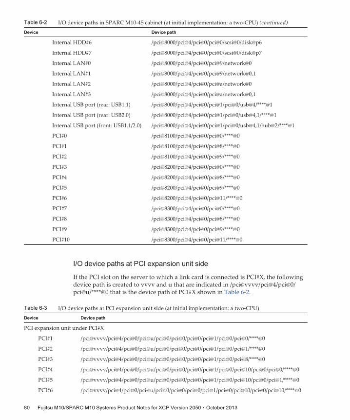
Table 6-2 I/O device paths in SPARC M10-4S cabinet (at initial implementation: a two-CPU) (continued)
Device Device path
Internal HDD#6 /pci@8000/pci@4/pci@0/pci@0/scsi@0/disk@p6
Internal HDD#7 /pci@8000/pci@4/pci@0/pci@0/scsi@0/disk@p7
Internal LAN#0 /pci@8000/pci@4/pci@0/pci@9/network@0
Internal LAN#1 /pci@8000/pci@4/pci@0/pci@9/network@0,1
Internal LAN#2 /pci@8000/pci@4/pci@0/pci@a/network@0
Internal LAN#3 /pci@8000/pci@4/pci@0/pci@a/network@0,1
Internal USB port (rear: USB1.1) /pci@8000/pci@4/pci@0/pci@1/pci@0/usb@4/****@1
Internal USB port (rear: USB2.0) /pci@8000/pci@4/pci@0/pci@1/pci@0/usb@4,1/****@1
Internal USB port (front: USB1.1/2.0) /pci@8000/pci@4/pci@0/pci@1/pci@0/usb@4,1/hub@2/****@1
PCI#0 /pci@8100/pci@4/pci@0/pci@0/****@0
PCI#1 /pci@8100/pci@4/pci@0/pci@8/****@0
PCI#2 /pci@8100/pci@4/pci@0/pci@9/****@0
PCI#3 /pci@8200/pci@4/pci@0/pci@0/****@0
PCI#4 /pci@8200/pci@4/pci@0/pci@8/****@0
PCI#5 /pci@8200/pci@4/pci@0/pci@9/****@0
PCI#6 /pci@8200/pci@4/pci@0/pci@11/****@0
PCI#7 /pci@8300/pci@4/pci@0/pci@0/****@0
PCI#8 /pci@8300/pci@4/pci@0/pci@8/****@0
PCI#9 /pci@8300/pci@4/pci@0/pci@9/****@0
PCI#10 /pci@8300/pci@4/pci@0/pci@11/****@0
Table 6-3 I/O device paths at PCI expansion unit side (at initial implementation: a two-CPU)
Device Device path
PCI expansion unit under PCI#X
PCI#1 /pci@vvvv/pci@4/pci@0/pci@u/pci@0/pci@0/pci@0/pci@1/pci@0/pci@0/****@0
PCI#2 /pci@vvvv/pci@4/pci@0/pci@u/pci@0/pci@0/pci@0/pci@1/pci@0/pci@1/****@0
PCI#3 /pci@vvvv/pci@4/pci@0/pci@u/pci@0/pci@0/pci@0/pci@1/pci@0/pci@8/****@0
PCI#4 /pci@vvvv/pci@4/pci@0/pci@u/pci@0/pci@0/pci@0/pci@1/pci@0/pci@10/pci@0/pci@0/****@0
PCI#5 /pci@vvvv/pci@4/pci@0/pci@u/pci@0/pci@0/pci@0/pci@1/pci@0/pci@10/pci@0/pci@1/****@0
PCI#6 /pci@vvvv/pci@4/pci@0/pci@u/pci@0/pci@0/pci@0/pci@1/pci@0/pci@10/pci@0/pci@10/****@0
I/O device paths at PCI expansion unit side
If the PCI slot on the server to which a link card is connected is PCI#X, the followingdevice path is created to vvvv and u that are indicated in /pci@vvvv/pci@4/pci@0/pci@u/****@0 that is the device path of PCI#X shown in Table 6-2.
Fujitsu M10/SPARC M10 Systems Product Notes for XCP Version 2050 ・ October 201380
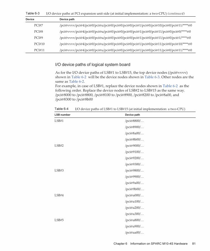
Table 6-3 I/O device paths at PCI expansion unit side (at initial implementation: a two-CPU) (continued)
Device Device path
PCI#7 /pci@vvvv/pci@4/pci@0/pci@u/pci@0/pci@0/pci@0/pci@1/pci@0/pci@10/pci@0/pci@11/****@0
PCI#8 /pci@vvvv/pci@4/pci@0/pci@u/pci@0/pci@0/pci@0/pci@1/pci@0/pci@11/pci@0/pci@0/****@0
PCI#9 /pci@vvvv/pci@4/pci@0/pci@u/pci@0/pci@0/pci@0/pci@1/pci@0/pci@11/pci@0/pci@1/****@0
PCI#10 /pci@vvvv/pci@4/pci@0/pci@u/pci@0/pci@0/pci@0/pci@1/pci@0/pci@11/pci@0/pci@10/****@0
PCI#11 /pci@vvvv/pci@4/pci@0/pci@u/pci@0/pci@0/pci@0/pci@1/pci@0/pci@11/pci@0/pci@11/****@0
Table 6-4 I/O device paths of LSB#1 to LSB#15 (at initial implementation: a two-CPU)
LSB number Device path
LSB#1 /pci@8800/…
/pci@8900/…
/pci@8a00/…
/pci@8b00/…
LSB#2 /pci@9000/…
/pci@9100/…
/pci@9200/…
/pci@9300/…
LSB#3 /pci@9800/…
/pci@9900/…
/pci@9a00/…
/pci@9b00/…
LSB#4 /pci@a000/…
/pci@a100/…
/pci@a200/…
/pci@a300/…
LSB#5 /pci@a800/…
/pci@a900/…
/pci@aa00/…
I/O device paths of logical system board
As for the I/O device paths of LSB#1 to LSB#15, the top device nodes (/pci@vvvv)shown in Table 6-2 will be the device nodes shown in Table 6-3. Other nodes are thesame as Table 6-2.For example, in case of LSB#1, replace the device nodes shown in Table 6-2 as thefollowing order. Replace the device nodes of LSB#2 to LSB#15 as the same way./pci@8000 to /pci@8800, /pci@8100 to /pci@8900, /pci@8200 to /pci@8a00, and/pci@8300 to /pci@8b00
Chapter 6 Information on SPARC M10-4S Hardware 81
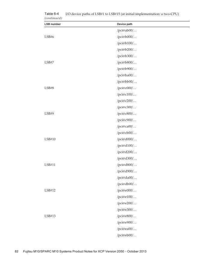
Table 6-4 I/O device paths of LSB#1 to LSB#15 (at initial implementation: a two-CPU)(continued)
LSB number Device path
/pci@ab00/…
LSB#6 /pci@b000/…
/pci@b100/…
/pci@b200/…
/pci@b300/…
LSB#7 /pci@b800/…
/pci@b900/…
/pci@ba00/…
/pci@bb00/…
LSB#8 /pci@c000/…
/pci@c100/…
/pci@c200/…
/pci@c300/…
LSB#9 /pci@c800/…
/pci@c900/…
/pci@ca00/…
/pci@cb00/…
LSB#10 /pci@d000/…
/pci@d100/…
/pci@d200/…
/pci@d300/…
LSB#11 /pci@d800/…
/pci@d900/…
/pci@da00/…
/pci@db00/…
LSB#12 /pci@e000/…
/pci@e100/…
/pci@e200/…
/pci@e300/…
LSB#13 /pci@e800/…
/pci@e900/…
/pci@ea00/…
/pci@eb00/…
Fujitsu M10/SPARC M10 Systems Product Notes for XCP Version 2050 ・ October 201382
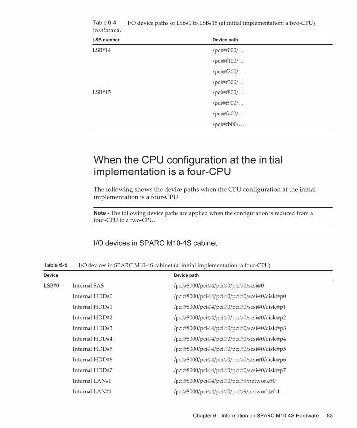
Table 6-4 I/O device paths of LSB#1 to LSB#15 (at initial implementation: a two-CPU)(continued)
LSB number Device path
LSB#14 /pci@f000/…
/pci@f100/…
/pci@f200/…
/pci@f300/…
LSB#15 /pci@f800/…
/pci@f900/…
/pci@fa00/…
/pci@fb00/…
Note - The following device paths are applied when the configuration is reduced from afour-CPU to a two-CPU.
Table 6-5 I/O devices in SPARC M10-4S cabinet (at initial implementation: a four-CPU)
Device Device path
LSB#0 Internal SAS /pci@8000/pci@4/pci@0/pci@0/scsi@0
Internal HDD#0 /pci@8000/pci@4/pci@0/pci@0/scsi@0/disk@p0
Internal HDD#1 /pci@8000/pci@4/pci@0/pci@0/scsi@0/disk@p1
Internal HDD#2 /pci@8000/pci@4/pci@0/pci@0/scsi@0/disk@p2
Internal HDD#3 /pci@8000/pci@4/pci@0/pci@0/scsi@0/disk@p3
Internal HDD#4 /pci@8000/pci@4/pci@0/pci@0/scsi@0/disk@p4
Internal HDD#5 /pci@8000/pci@4/pci@0/pci@0/scsi@0/disk@p5
Internal HDD#6 /pci@8000/pci@4/pci@0/pci@0/scsi@0/disk@p6
Internal HDD#7 /pci@8000/pci@4/pci@0/pci@0/scsi@0/disk@p7
Internal LAN#0 /pci@8000/pci@4/pci@0/pci@9/network@0
Internal LAN#1 /pci@8000/pci@4/pci@0/pci@9/network@0,1
When the CPU configuration at the initialimplementation is a four-CPU
The following shows the device paths when the CPU configuration at the initialimplementation is a four-CPU
I/O devices in SPARC M10-4S cabinet
Chapter 6 Information on SPARC M10-4S Hardware 83
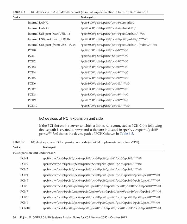
Table 6-5 I/O devices in SPARC M10-4S cabinet (at initial implementation: a four-CPU) (continued)
Device Device path
Internal LAN#2 /pci@8400/pci@4/pci@0/pci@a/network@0
Internal LAN#3 /pci@8400/pci@4/pci@0/pci@a/network@0,1
Internal USB port (rear: USB1.1) /pci@8000/pci@4/pci@0/pci@1/pci@0/usb@4/****@1
Internal USB port (rear: USB2.0) /pci@8000/pci@4/pci@0/pci@1/pci@0/usb@4,1/****@1
Internal USB port (front: USB1.1/2.0) /pci@8000/pci@4/pci@0/pci@1/pci@0/usb@4,1/hub@2/****@1
PCI#0 /pci@8100/pci@4/pci@0/pci@0/****@0
PCI#1 /pci@8500/pci@4/pci@0/pci@8/****@0
PCI#2 /pci@8500/pci@4/pci@0/pci@9/****@0
PCI#3 /pci@8200/pci@4/pci@0/pci@0/****@0
PCI#4 /pci@8200/pci@4/pci@0/pci@8/****@0
PCI#5 /pci@8600/pci@4/pci@0/pci@9/****@0
PCI#6 /pci@8600/pci@4/pci@0/pci@11/****@0
PCI#7 /pci@8300/pci@4/pci@0/pci@0/****@0
PCI#8 /pci@8300/pci@4/pci@0/pci@8/****@0
PCI#9 /pci@8700/pci@4/pci@0/pci@9/****@0
PCI#10 /pci@8700/pci@4/pci@0/pci@11/****@0
Table 6-6 I/O device paths at PCI expansion unit side (at initial implementation: a four-CPU)
Device Device path
PCI expansion unit under PCI#X
PCI#1 /pci@vvvv/pci@4/pci@0/pci@u/pci@0/pci@0/pci@0/pci@1/pci@0/pci@0/****@0
PCI#2 /pci@vvvv/pci@4/pci@0/pci@u/pci@0/pci@0/pci@0/pci@1/pci@0/pci@1/****@0
PCI#3 /pci@vvvv/pci@4/pci@0/pci@u/pci@0/pci@0/pci@0/pci@1/pci@0/pci@8/****@0
PCI#4 /pci@vvvv/pci@4/pci@0/pci@u/pci@0/pci@0/pci@0/pci@1/pci@0/pci@10/pci@0/pci@0/****@0
PCI#5 /pci@vvvv/pci@4/pci@0/pci@u/pci@0/pci@0/pci@0/pci@1/pci@0/pci@10/pci@0/pci@1/****@0
PCI#6 /pci@vvvv/pci@4/pci@0/pci@u/pci@0/pci@0/pci@0/pci@1/pci@0/pci@10/pci@0/pci@10/****@0
PCI#7 /pci@vvvv/pci@4/pci@0/pci@u/pci@0/pci@0/pci@0/pci@1/pci@0/pci@10/pci@0/pci@11/****@0
PCI#8 /pci@vvvv/pci@4/pci@0/pci@u/pci@0/pci@0/pci@0/pci@1/pci@0/pci@11/pci@0/pci@0/****@0
PCI#9 /pci@vvvv/pci@4/pci@0/pci@u/pci@0/pci@0/pci@0/pci@1/pci@0/pci@11/pci@0/pci@1/****@0
PCI#10 /pci@vvvv/pci@4/pci@0/pci@u/pci@0/pci@0/pci@0/pci@1/pci@0/pci@11/pci@0/pci@10/****@0
I/O devices at PCI expansion unit side
If the PCI slot on the server to which a link card is connected is PCI#X, the followingdevice path is created to vvvv and u that are indicated in /pci@vvvv/pci@4/pci@0/pci@u/****@0 that is the device path of PCI#X shown in Table 6-5.
Fujitsu M10/SPARC M10 Systems Product Notes for XCP Version 2050 ・ October 201384
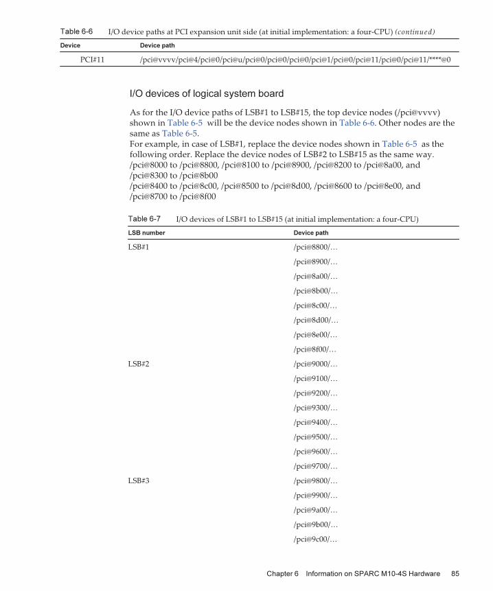
Table 6-6 I/O device paths at PCI expansion unit side (at initial implementation: a four-CPU) (continued)
Device Device path
PCI#11 /pci@vvvv/pci@4/pci@0/pci@u/pci@0/pci@0/pci@0/pci@1/pci@0/pci@11/pci@0/pci@11/****@0
Table 6-7 I/O devices of LSB#1 to LSB#15 (at initial implementation: a four-CPU)
LSB number Device path
LSB#1 /pci@8800/…
/pci@8900/…
/pci@8a00/…
/pci@8b00/…
/pci@8c00/…
/pci@8d00/…
/pci@8e00/…
/pci@8f00/…
LSB#2 /pci@9000/…
/pci@9100/…
/pci@9200/…
/pci@9300/…
/pci@9400/…
/pci@9500/…
/pci@9600/…
/pci@9700/…
LSB#3 /pci@9800/…
/pci@9900/…
/pci@9a00/…
/pci@9b00/…
/pci@9c00/…
I/O devices of logical system board
As for the I/O device paths of LSB#1 to LSB#15, the top device nodes (/pci@vvvv)shown in Table 6-5 will be the device nodes shown in Table 6-6. Other nodes are thesame as Table 6-5.For example, in case of LSB#1, replace the device nodes shown in Table 6-5 as thefollowing order. Replace the device nodes of LSB#2 to LSB#15 as the same way./pci@8000 to /pci@8800, /pci@8100 to /pci@8900, /pci@8200 to /pci@8a00, and/pci@8300 to /pci@8b00/pci@8400 to /pci@8c00, /pci@8500 to /pci@8d00, /pci@8600 to /pci@8e00, and/pci@8700 to /pci@8f00
Chapter 6 Information on SPARC M10-4S Hardware 85
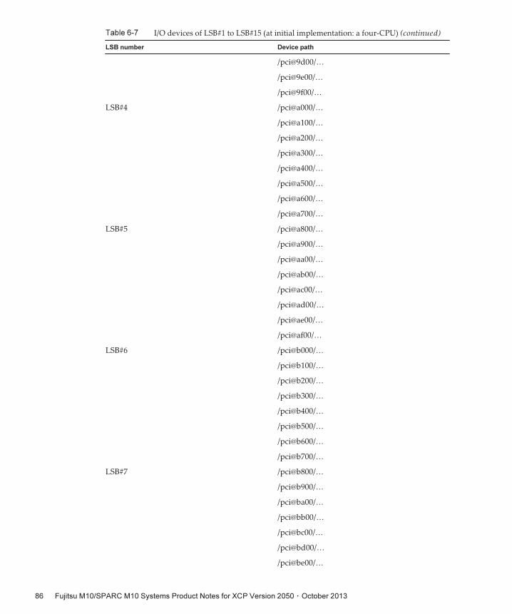
Table 6-7 I/O devices of LSB#1 to LSB#15 (at initial implementation: a four-CPU) (continued)
LSB number Device path
/pci@9d00/…
/pci@9e00/…
/pci@9f00/…
LSB#4 /pci@a000/…
/pci@a100/…
/pci@a200/…
/pci@a300/…
/pci@a400/…
/pci@a500/…
/pci@a600/…
/pci@a700/…
LSB#5 /pci@a800/…
/pci@a900/…
/pci@aa00/…
/pci@ab00/…
/pci@ac00/…
/pci@ad00/…
/pci@ae00/…
/pci@af00/…
LSB#6 /pci@b000/…
/pci@b100/…
/pci@b200/…
/pci@b300/…
/pci@b400/…
/pci@b500/…
/pci@b600/…
/pci@b700/…
LSB#7 /pci@b800/…
/pci@b900/…
/pci@ba00/…
/pci@bb00/…
/pci@bc00/…
/pci@bd00/…
/pci@be00/…
Fujitsu M10/SPARC M10 Systems Product Notes for XCP Version 2050 ・ October 201386
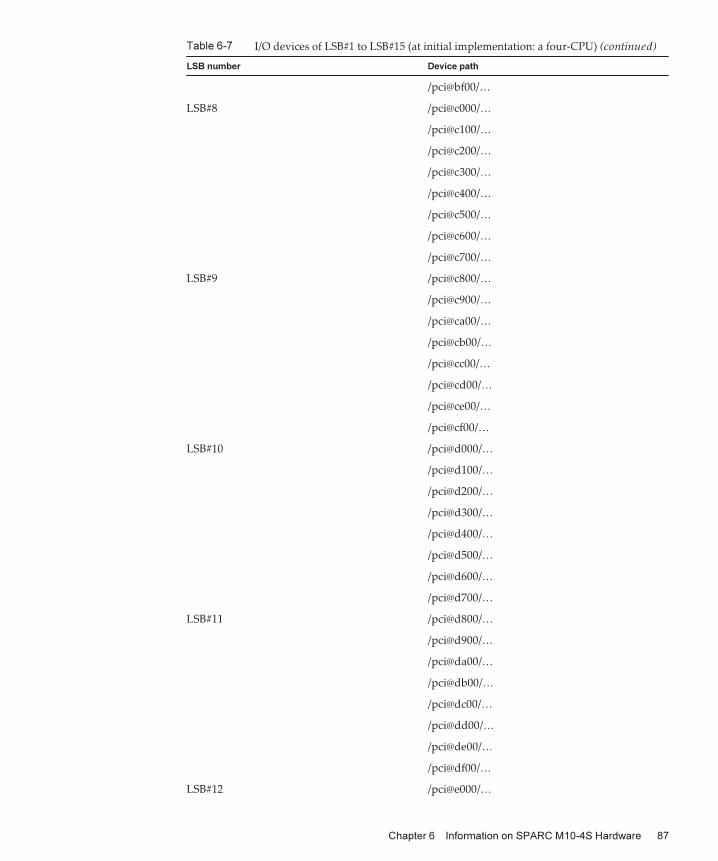
Table 6-7 I/O devices of LSB#1 to LSB#15 (at initial implementation: a four-CPU) (continued)
LSB number Device path
/pci@bf00/…
LSB#8 /pci@c000/…
/pci@c100/…
/pci@c200/…
/pci@c300/…
/pci@c400/…
/pci@c500/…
/pci@c600/…
/pci@c700/…
LSB#9 /pci@c800/…
/pci@c900/…
/pci@ca00/…
/pci@cb00/…
/pci@cc00/…
/pci@cd00/…
/pci@ce00/…
/pci@cf00/…
LSB#10 /pci@d000/…
/pci@d100/…
/pci@d200/…
/pci@d300/…
/pci@d400/…
/pci@d500/…
/pci@d600/…
/pci@d700/…
LSB#11 /pci@d800/…
/pci@d900/…
/pci@da00/…
/pci@db00/…
/pci@dc00/…
/pci@dd00/…
/pci@de00/…
/pci@df00/…
LSB#12 /pci@e000/…
Chapter 6 Information on SPARC M10-4S Hardware 87
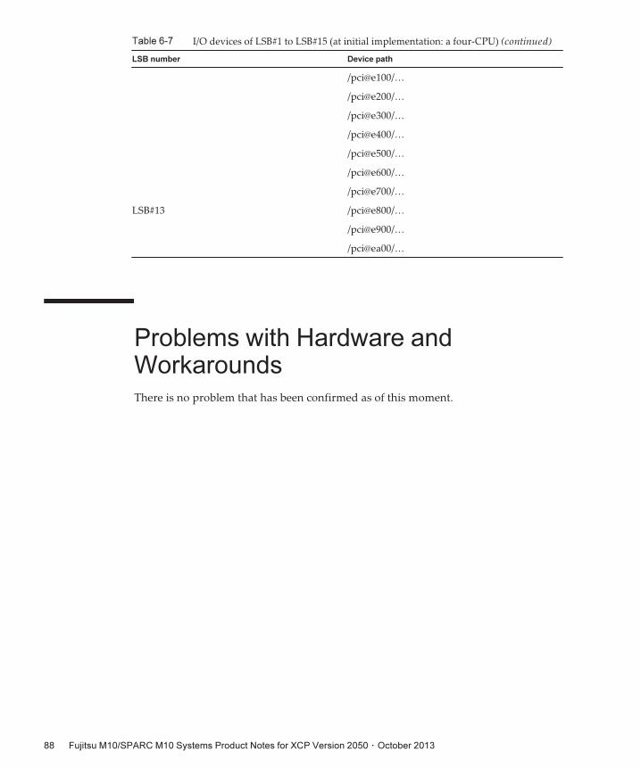
Table 6-7 I/O devices of LSB#1 to LSB#15 (at initial implementation: a four-CPU) (continued)
LSB number Device path
/pci@e100/…
/pci@e200/…
/pci@e300/…
/pci@e400/…
/pci@e500/…
/pci@e600/…
/pci@e700/…
LSB#13 /pci@e800/…
/pci@e900/…
/pci@ea00/…
Problems with Hardware andWorkaroundsThere is no problem that has been confirmed as of this moment.
Fujitsu M10/SPARC M10 Systems Product Notes for XCP Version 2050 ・ October 201388
Chapter 7
Information on PCI Expansion UnitHardware
This chapter describes special instructions and problems concerning the PCIexpansion unit hardware.■ Problems with PCI Expansion Units and Workarounds
Problems with PCI Expansion Unitsand WorkaroundsThis section describes problems with PCI Expansion unit and workarounds for eachversion.
Problems relating to all the versions of PCIExpansion unit formware and their workarounds
The following table shows problems that might occur in any versions of PCIExpansion unit firmware being supported and workarounds for them.
89
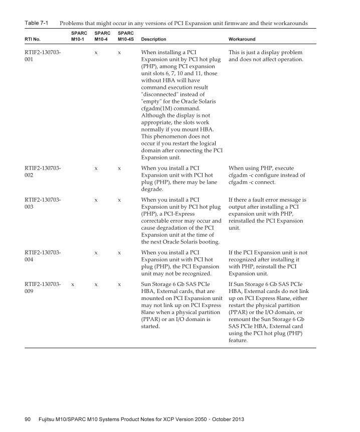
Table 7-1 Problems that might occur in any versions of PCI Expansion unit firmware and their workarounds
RTI No.
SPARC
M10-1
SPARC
M10-4
SPARC
M10-4S Description Workaround
RTIF2-130703-001
x x When installing a PCIExpansion unit by PCI hot plug(PHP), among PCI expansionunit slots 6, 7, 10 and 11, thosewithout HBA will havecommand execution result"disconnected" instead of"empty" for the Oracle Solariscfgadm(1M) command.Although the display is notappropriate, the slots worknormally if you mount HBA.This phenomenon does notoccur if you restart the logicaldomain after connecting the PCIExpansion unit.
This is just a display problemand does not affect operation.
RTIF2-130703-002
x x When you install a PCIExpansion unit with PCI hotplug (PHP), there may be lanedegrade.
When using PHP, executecfgadm -c configure instead ofcfgadm -c connect.
RTIF2-130703-003
x x When you install a PCIExpansion unit by PCI hot plug(PHP), a PCI-Expresscorrectable error may occur andcause degradation of the PCIExpansion unit at the time ofthe next Oracle Solaris booting.
If there a fault error message isoutput after installing a PCIexpansion unit with PHP,reinstalled the PCI Expansionunit.
RTIF2-130703-004
x x When you install a PCIExpansion unit with PCI hotplug (PHP), the PCI Expansionunit may not be recognized.
If the PCI Expansion unit is notrecognized after installing itwith PHP, reinstall the PCIExpansion unit.
RTIF2-130703-009
x x x Sun Storage 6 Gb SAS PCIeHBA, External cards, that aremounted on PCI Expansion unitmay not link up on PCI Express8lane when a physical partition(PPAR) or an I/O domain isstarted.
If Sun Storage 6 Gb SAS PCIeHBA, External cards do not linkup on PCI Express 8lane, eitherrestart the physical partition(PPAR) or the I/O domain, orremount the Sun Storage 6 GbSAS PCIe HBA, External cardusing the PCI hot plug (PHP)feature.
Fujitsu M10/SPARC M10 Systems Product Notes for XCP Version 2050 ・ October 201390
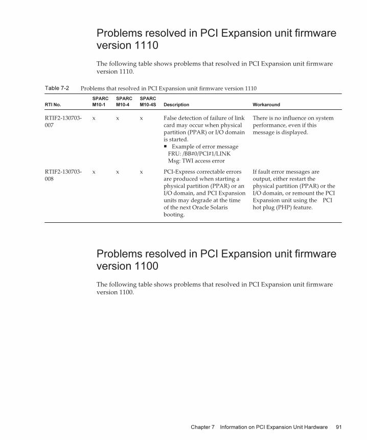
Table 7-2 Problems that resolved in PCI Expansion unit firmware version 1110
RTI No.
SPARC
M10-1
SPARC
M10-4
SPARC
M10-4S Description Workaround
RTIF2-130703-007
x x x False detection of failure of linkcard may occur when physicalpartition (PPAR) or I/O domainis started.■ Example of error message
FRU: /BB#0/PCI#1/LINKMsg: TWI access error
There is no influence on systemperformance, even if thismessage is displayed.
RTIF2-130703-008
x x x PCI-Express correctable errorsare produced when starting aphysical partition (PPAR) or anI/O domain, and PCI Expansionunits may degrade at the timeof the next Oracle Solarisbooting.
If fault error messages areoutput, either restart thephysical partition (PPAR) or theI/O domain, or remount the PCIExpansion unit using the PCIhot plug (PHP) feature.
Problems resolved in PCI Expansion unit firmwareversion 1110
The following table shows problems that resolved in PCI Expansion unit firmwareversion 1110.
Problems resolved in PCI Expansion unit firmwareversion 1100
The following table shows problems that resolved in PCI Expansion unit firmwareversion 1100.
Chapter 7 Information on PCI Expansion Unit Hardware 91
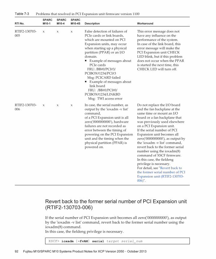
Table 7-3 Problems that resolved in PCI Expansion unit firmware version 1100
RTI No.
SPARC
M10-1
SPARC
M10-4
SPARC
M10-4S Description Workaround
RTIF2-130703-005
x x x False detection of failures ofPCIe cards or link boards,which are mounted on PCIExpansion units, may occurwhen starting up a physicalpartition (PPAR) or an I/Odomain.■ Example of messages about
PCIe cardsFRU: /BB#0/PCI#3/
PCIBOX#1234/PCI#3Msg: PCICARD failed
■ Example of messages aboutlink board
FRU: /BB#0/PCI#0/PCIBOX#1234/LINKBD
Msg: TWI access error
This error message does nothave any influence on theperformance of the system.In case of the link board, thiserror message will make thePCI Expansion unit CHECKLED blink, but if this problemdoes not occur when the PPARis started the next time, thisCHECK LED will turn off.
RTIF2-130703-006
x x x In case, the serial number, asoutput by the 'ioxadm -v list'command,of a PCI Expansion unit is allzero('0000000000'), hardwarefailures are not recorded aserror between the timing ofpowering on the PCI Expansionunit and the timing when thephysical partition (PPAR) ispowered on.
Do not replace the I/O boardand the fan backplane at thesame time or mount an I/Oboard or a fan backplane thatwas previously used elsewhereon a PCI Expansion unit.If the serial number of PCIExpansion unit becomes allzero('0000000000'), as output bythe 'ioxadm -v list' command,revert back to the former serialnumber using the ioxadm(8)command of XSCF firmware.In this case, the fieldengprivilege is necessary.For detail, see "Revert back tothe former serial number of PCIExpansion unit (RTIF2-130703-006)".
XSCF> ioxadm [-fvAM] serial target serial_num
Revert back to the former serial number of PCI Expansion unit(RTIF2-130703-006)
If the serial number of PCI Expansion unit becomes all zero('0000000000'), as outputby the 'ioxadm -v list' command, revert back to the former serial number using theioxadm(8) command.In this case, the fieldeng privilege is necessary.
Fujitsu M10/SPARC M10 Systems Product Notes for XCP Version 2050 ・ October 201392
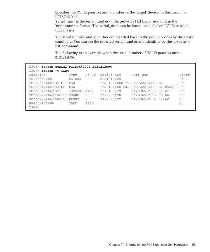
XSCF> ioxadm serial PCIBOX#0000 2121212006XSCF> ioxadm -v listLocation Type FW Ve Serial Num Part Num State
PCIBOX#2006 PCIBOX - 2121212006 On
PCIBOX#2006/PSU#0 PSU - FEJD1201000170 CA01022-0750-D/ On
PCIBOX#2006/PSU#1 PSU - FEJD1245001342 CA01022-0750-D/7060988 On
PCIBOX#2006/IOB IOBOARD 1110 PP121001JM CA20365-B66X 007AF On
PCIBOX#2006/LINKBD BOARD - PP123300TR CA20365-B60X 001AA On
PCIBOX#2006/FANBP FANBP - PP120904SY CA20365-B68X 004AC On
BB#00-PCI#00 CARD 1110 On
XSCF>
Specifies the PCI Expansion unit identifier as the 'target' device. In this case, it isPCIBOX#0000.'serial_num' is the serial number of the previous PCI Expansion unit in the'nnnnnnnnnn' format. The 'serial_num' can be found on a label on PCI Expansionunit chassis.
The serial number and identifier are reverted back to the previous ones by the abovecommand. You can see the reverted serial number and identifier by the 'ioxadm -vlist' command.
The following is an example when the serial number of PCI Expansion unit is2121212006:
Chapter 7 Information on PCI Expansion Unit Hardware 93

Fujitsu M10/SPARC M10 Systems Product Notes for XCP Version 2050 ・ October 201394
Chapter 8
Contents of Revision ofDocumentation
This chapter describes the latest information which has been confirmed afterdocumentations related to SPARC M10 Systems are released and contents of revisionof documentations.■ Contents of revision of PCI Expansion Unit for SPARC M10 Systems ServiceManual
■ Contents of Revision of SPARC M10 Systems System Operation and AdministrationGuide
■ Contents of Revision of SPARC M10 Systems Domain Configuration Guide
■ Contents of Revision of SPARC M10 Systems Getting Started Guide
Contents of revision of PCI ExpansionUnit for SPARCM10 Systems ServiceManualThis section describes the currently confirmed contents of revision of the PCIExpansion Unit for SPARC M10 Systems Service Manual.
95
Table 8-1 Contents of revision of PCI Expansion Unit for SPARC M10 Systems Service Manual
Section number or name Contents of revision
15.1 The following note will be added in "15.1 Configuration of I/O Board."Note - Do not replace the I/O board and the fan backplane at the same time. If I/Oboard and the fan backplane are replaced at the same time, the serial number of thePCI Expansion unit, as output by the 'ioxadm -v list' command, is changed to allzero('0000000000'). If the serial number of the PCI Expansion unit has been changedto all zero('0000000000'), it is necessary to use the ioxadm(8) command of the XSCFfirmware to revert back to the former serial number.When replacing the I/O board and the fan backplane at the same time, first replaceone of the two, start the physical partition (PPAR) that is connected to the PCIExpansion unit and check for any error log regarding the PCI Expansion unit. Ifthere is no such error log, replace the remaining Field Replaceable Unit (FRU).
16.1 The following note will be added in "16.1 Location of Fan Backplane."Note - Do not replace the I/O board and the fan backplane at the same time. If I/Oboard and the fan backplane are replaced at the same time, the serial number of thePCI Expansion unit, as output by the 'ioxadm -v list' command, is changed to allzero('0000000000'). If the serial number of the PCI Expansion unit has been changedto all zero('0000000000'), it is necessary to use the ioxadm(8) command of the XSCFfirmware to revert back to the former serial number.When replacing the I/O board and the fan backplane at the same time, first replaceone of the two, start the physical partition (PPAR) that is connected to the PCIExpansion unit and check for any error log regarding the PCI Expansion unit. Ifthere is no such error log, replace the remaining Field Replaceable Unit (FRU).
Contents of Revision of SPARCM10Systems System Operation andAdministration GuideThis section describes the contents of revision of the SPARC M10 Systems SystemOperation and Administration Guide.
Fujitsu M10/SPARC M10 Systems Product Notes for XCP Version 2050 ・ October 201396
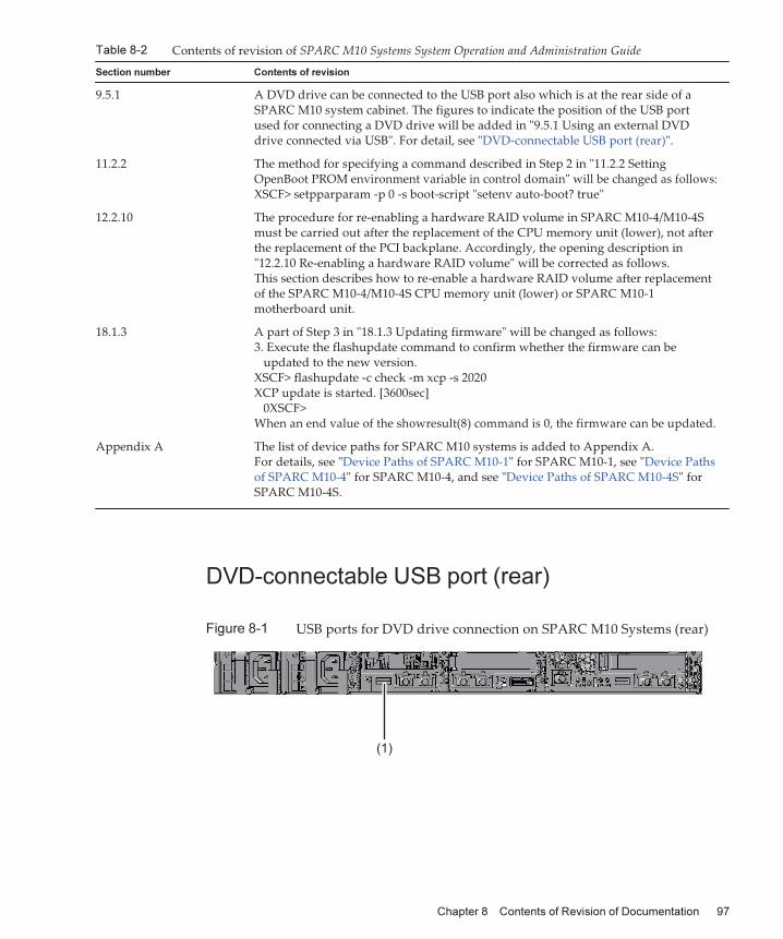
Table 8-2 Contents of revision of SPARC M10 Systems System Operation and Administration Guide
Section number Contents of revision
9.5.1 A DVD drive can be connected to the USB port also which is at the rear side of aSPARC M10 system cabinet. The figures to indicate the position of the USB portused for connecting a DVD drive will be added in "9.5.1 Using an external DVDdrive connected via USB". For detail, see "DVD-connectable USB port (rear)".
11.2.2 The method for specifying a command described in Step 2 in "11.2.2 SettingOpenBoot PROM environment variable in control domain" will be changed as follows:XSCF> setpparparam -p 0 -s boot-script "setenv auto-boot? true"
12.2.10 The procedure for re-enabling a hardware RAID volume in SPARC M10-4/M10-4Smust be carried out after the replacement of the CPU memory unit (lower), not afterthe replacement of the PCI backplane. Accordingly, the opening description in"12.2.10 Re-enabling a hardware RAID volume" will be corrected as follows.This section describes how to re-enable a hardware RAID volume after replacementof the SPARC M10-4/M10-4S CPU memory unit (lower) or SPARC M10-1motherboard unit.
18.1.3 A part of Step 3 in "18.1.3 Updating firmware" will be changed as follows:3. Execute the flashupdate command to confirm whether the firmware can be
updated to the new version.XSCF> flashupdate -c check -m xcp -s 2020XCP update is started. [3600sec]
0XSCF>When an end value of the showresult(8) command is 0, the firmware can be updated.
Appendix A The list of device paths for SPARC M10 systems is added to Appendix A.For details, see "Device Paths of SPARC M10-1" for SPARC M10-1, see "Device Pathsof SPARC M10-4" for SPARC M10-4, and see "Device Paths of SPARC M10-4S" forSPARC M10-4S.
(1)
DVD-connectable USB port (rear)
Figure 8-1 USB ports for DVD drive connection on SPARC M10 Systems (rear)
Chapter 8 Contents of Revision of Documentation 97
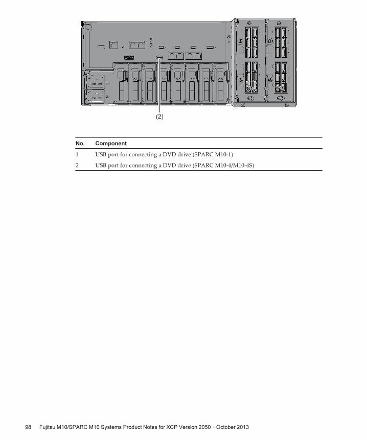
(2)
No. Component
1 USB port for connecting a DVD drive (SPARC M10-1)
2 USB port for connecting a DVD drive (SPARC M10-4/M10-4S)
Fujitsu M10/SPARC M10 Systems Product Notes for XCP Version 2050 ・ October 201398
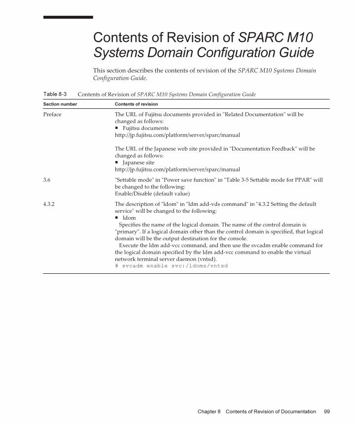
Table 8-3 Contents of Revision of SPARC M10 Systems Domain Configuration Guide
Section number Contents of revision
Preface The URL of Fujitsu documents provided in "Related Documentation" will bechanged as follows:■ Fujitsu documentshttp://jp.fujitsu.com/platform/server/sparc/manual
The URL of the Japanese web site provided in "Documentation Feedback" will bechanged as follows:■ Japanese sitehttp://jp.fujitsu.com/platform/server/sparc/manual
3.6 "Settable mode" in "Power save function" in "Table 3-5 Settable mode for PPAR" willbe changed to the following:Enable/Disable (default value)
4.3.2 The description of "ldom" in "ldm add-vds command" in "4.3.2 Setting the defaultservice" will be changed to the following:■ ldom
Specifies the name of the logical domain. The name of the control domain is"primary". If a logical domain other than the control domain is specified, that logicaldomain will be the output destination for the console.
Execute the ldm add-vcc command, and then use the svcadm enable command forthe logical domain specified by the ldm add-vcc command to enable the virtualnetwork terminal server daemon (vntsd).# svcadm enable svc:/ldoms/vntsd
Contents of Revision of SPARCM10Systems Domain Configuration GuideThis section describes the contents of revision of the SPARC M10 Systems DomainConfiguration Guide.
Chapter 8 Contents of Revision of Documentation 99
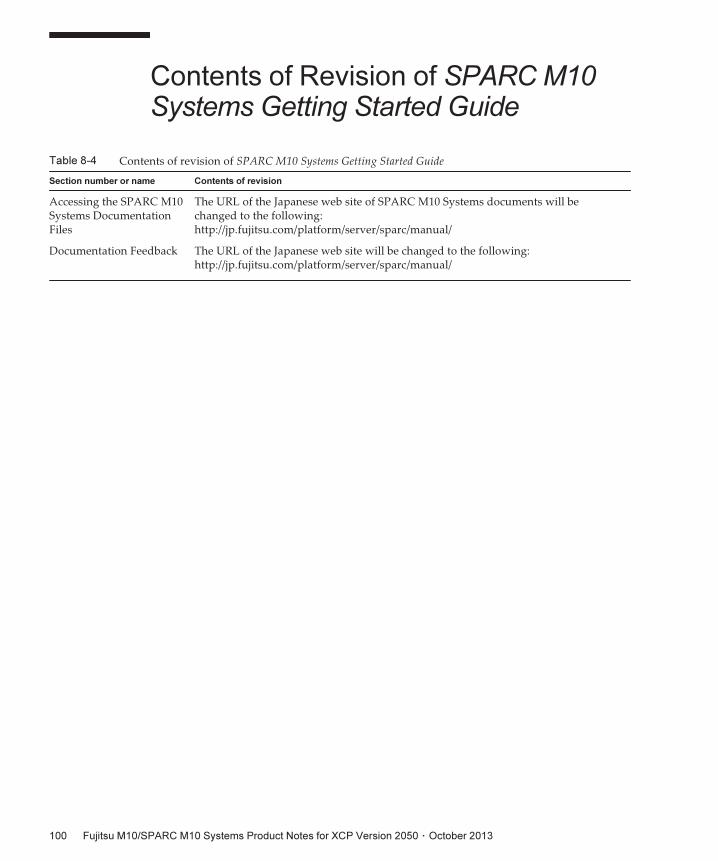
Table 8-4 Contents of revision of SPARC M10 Systems Getting Started Guide
Section number or name Contents of revision
Accessing the SPARC M10Systems DocumentationFiles
The URL of the Japanese web site of SPARC M10 Systems documents will bechanged to the following:http://jp.fujitsu.com/platform/server/sparc/manual/
Documentation Feedback The URL of the Japanese web site will be changed to the following:http://jp.fujitsu.com/platform/server/sparc/manual/
Contents of Revision of SPARCM10Systems Getting Started Guide
Fujitsu M10/SPARC M10 Systems Product Notes for XCP Version 2050 ・ October 2013100