Embed Size (px)
Citation preview

Jabber XCP Server
Configuration Guide
Product Version: XCP 5.1Document Version: B
Release Date: June 2006

Disclaimers
Copyright 2006, Jabber, Inc.
The information contained in this document is proprietary to Jabber, Inc. This information is considered confidential and is not to be disclosed to any outside parties without the express written consent of Jabber, Inc.
This document is provided for information purposes only, and the information herein is subject to change without notice. Jabber, Inc. does not provide any warranties covering and specifically disclaims any liability in connection with this document.
TrademarksJABBER® and the light bulb logo are either trademarks or registered trademarks of Jabber, Inc.
All other trademarks are the property of their respective owners.
Contact Information
1899 Wynkoop Street, Suite 600 Denver, Colorado 80202 303-308-3231
Page ii Jabber XCP 5.1 Configuration Guide

Table of Contents
Chapter 1. Overview of the Jabber XCP Server .............................................. 7XCP 5.1 Architecture 8
Component Descriptions 9Router Plugin Descriptions 11
New XCP Functionality 11New Features in XCP 5.1 11New Features in XCP 5.0 12
The Jabber XCP Controller 16Configuration Views 17Areas on the Main Screen 18Online Help 20
Configuration Guidelines 20Optimal Network Configuration 21Firewall Considerations 21Hardware Considerations 22
Chapter 2. Advanced File Transfer ................................................................. 23Architectural Overview 24Configuring the Advanced File Transfer Handler 25Configuring an Open Port 30HTTP File Transfer Protocol 31
Introduction 31Requirements 31Process Use Cases 32Security Considerations 36IANA Considerations 36Jabber Registrar Considerations 36XML Schemas 36Notes 37
Chapter 3. Logging............................................................................................ 39Configuring Syslog for Red Hat Linux 40Setting the Log Level for Router-Generated Packets 40
Jabber XCP 5.1 Configuration Guide Page iii

Jabberd Logger Configuration 42Selecting Namespaces 44Specifying Host Filters 45Configuring Loggers and Log Levels 45Formatting Logs 47
JSM Logging 48Packet Logs 50Session Logs 50Message Logs 51
Message Archiver Logging 51Statistics Logging 53Component Logging (Jlog) 54
Configuring the Filtered Syslog Logger 55Configuring the Filtered Stream Logger 57Adding a New Custom Logger 58
Chapter 4. Server-to-Server ............................................................................ 59Configuring Server-to-Server 62Configuring an Open Port 63Configuration Descriptions 65
Outgoing Connection Attempt Rules 65Authorized Addresses 66
Chapter 5. LaunchBroker................................................................................ 67Configuring the LaunchBroker Component 67Configuring the WebEx Collaboration Command 72
Before you Begin 72Configuration 72
Configuring the Breeze Collaboration Command 74System Requirements 74Setting up your Breeze Server 74Configuration 75
Configuring a Custom LaunchBroker Command 76
Chapter 6. SNMP.............................................................................................. 79Net-snmp Agent 79Management Information Bases 80Counters 81
Counters Available for All Components 81Command Manager Counters 81Connection Manager Counters 81File Transfer Proxy Counters 82JSM Counters 82Router Counters 82Server-to-Server Counters 83Text Conferencing Counters 83Waitlist Counters 83Web Services Counters 83
Enabling SNMP 84
Page iv Jabber XCP 5.1 Configuration Guide

Chapter 7. Single Domain Name Support....................................................... 85Overview 85
Which Components to Use with SDNS 86Choosing a Mapping Algorithm 87
Configuring SDNS in Geographically Dispersed Installations 89Example – Configuring SDNS for Text Conferencing 90Example – Configuring SDNS for JSM and Information Broker 94
Configuring SDNS in Local Installations 101Configuring SDNS for LDAP 102
Chapter 8. WebServices.................................................................................. 105Configuring Web Services 105
Add a Web Services Component 106Configure a Web Services Connection Manager 107Add Web Services as a Jabber Administrator 111Configure a Web Services Administrator 111
Service-Specific Configurations 112Broadcast Messages 112Offline Messaging 114Information Broker 115
Invoking Services from a SOAP-over-HTTP Client 115Web Services Definition Language Files 116
Chapter 9. HTTP Polling Connections.......................................................... 117
Chapter 10. Setting Up Active Directory Authentication............................ 121Configure a Jabber Directory Suite Component 121
Configure a Directory Server 123Configure an LDAP Database 124
Configure JSM to use JDS 127
Jabber XCP 5.1 Configuration Guide Page v

Page vi Jabber XCP 5.1 Configuration Guide

Chapter 1. Overview of the Jabber XCP Server
Jabber Inc.’s new release of the Extensible Communications Platform (XCP) server (version 5.1) contains a number of new features and components. This chapter provides a high-level diagram of the Jabber XCP architecture, and an overview of each new feature in addition to information about configuration, namespaces, and logging.
The following sections are provided:
• XCP 5.1 Architecture• New XCP Functionality• The Jabber XCP Controller• Configuration Guidelines
Jabber XCP 5.1 Configuration Guide Overview of the Jabber XCP Server Page 7

XCP 5.1 Architecture
XCP 5.1 ArchitectureFigure 1 illustrates the architecture of the Jabber XCP server, release 5.1. It includes support for the Sametime Gateway.
Figure 1. XCP 5.1 Architectural Overview
LaunchBroker
Java LaunchBroker
Basic FileTransfer
Wait ListService
Clients
Connection Manager
XMPP Client, Server
HTTP Config,Poll,SOAP
External Servers
Connectors
ClientXMPP
S2SXMPPSMTP
OfflineE-mail
SMS,WAP,IMPS
WebClient DesktopClient
Polling XMPP
Admin Console
SDKs(C++, Java)
HTTP
(To All)SNMP Agent AgentX Custom
DynamicRouting
WebEx
InfoBrokerDatabase
Memory AdvancedFile Transfer
AuthZ,Modify,Filter
Jabber Session ManagerOffline
Auth (Z,N)
Disco
Presence
Roster
Mirror
EventBroker Archive Router
ConfigManager
ComponentPresence
SQL
SDNSAlgorithm
Presence Mirror
Msg Archiver
Jabber UserDirectory
HTTP Binding
DataSources
JDSAuth
Search
CG
VcardLDAP
Custom
Breeze
Custom
TCMutli User Chat
Persistent
Custom/EventBroker
Web ServicesPresence
Messaging
InfoBroker
Page 8 Overview of the Jabber XCP Server Jabber XCP 5.1 Configuration Guide

XCP 5.1 Architecture
Component DescriptionsComponents are extensions of the Jabber XCP server that can be started and stopped independent of the router, jabberd. For example, you can start and stop the Text Conferencing component without bringing down the router (although your users will lose text conferencing capability if you do). The Components area in the Jabber XCP Controller is where you add, modify, and remove external server components. You can also start and stop individual components from this area.
After you install the Jabber XCP server, you must add the components that you want to make available to your users. If desired, you can use the server’s SDNS feature to install multiple copies of the same component to distribute it across hosts and to increase your system performance and reliability.
The components are described as follows:
• Connection Manager (CM) – Enables clients and other servers to connect to the Jabber XCP server. You can configure multiple connection managers to enable different types of connections or to scale the system to accept more connections.
• File Transfer Proxy – The File Transfer Proxy component allows you to enable server-based file transfer capabilities via a JEP-65: SOCKS5 Bytestreams proxy. The component acts as a SOCKS5 proxy server, and allows byte streams to be transferred between two Jabber clients.
• Information Broker – Provides the capability for customers to create applications through which users can publish, subscribe to, and access information that is organized by meaningful categories.
• Jabber Directory Suite (JDS) – Provides an interface between the Jabber server and version 3-compliant LDAP or ADS directory services. It handles authentication, and enables the retrieval of vCard information and the use of Community Groups.
• Jabber User Directory (JUD) – A searchable directory to which users on the server can subscribe. You can use it to create a searchable directory of all users on your Jabber server. (The JUD is commonly used for a directory when JDS with LDAP is not being used.)
• Java LaunchBroker – Previously called the Java External Command Interface (JECI), this component performs the same function as the LaunchBroker component, but allows custom commands to be written in Java. As with LaunchBroker, theses commands must comply with JEP-50: Ad-Hoc Commands.
Jabber XCP 5.1 Configuration Guide Overview of the Jabber XCP Server Page 9

XCP 5.1 Architecture
• LaunchBroker – Previously called External Command Interface (ECI), this component integrates with the WebEx and Breeze collaboration services. It allows Jabber client users to create WebEx and Breeze meetings and to send meeting invitations to contacts. The component also allows you to add your own custom JEP-0050 Ad-Hoc Commands.
• Message Archiver – Logs all messages sent to and from the server, including basic IM, text conferences, and broadcast messages. You must have a supported database (Oracle, PostgreSQL, or MS SQL) to use this feature.
• Open Port – Allows you to configure a custom component with a non-validated configuration or a component that is used for testing purposes. It also allows you to associate a host filter with a component that connects to the multi-accept port.
• Presence Mirror – Enables the storage of user presence information in a database on a near real-time basis. You must have a supported database (Oracle, PostgreSQL, or MS SQL) to use this feature.
• Router-to-Router – Allows a connection between two routers that are not in the same cluster or subnet. This component must be configured on the router that is initiating the connection. Its configuration simply requires the IP address, Port, and Password of the router to which it is connecting.
• Single Domain Name Support (SDNS) – Provides a means of distributing the load for a single Jabber domain over multiple components. For example, if you want the users connected to routers A and B to participate in text conference rooms on either router, you must configure an SDNS component on both routers. The components that you can configure for SDNS include JSM, Information Broker, and Text Conferencing.
• Text Conferencing (TC) – Enables Jabber users to participate in online conference rooms. It provides the ability to load core gears, which control the behavior of text conferencing on your system. It also permits the storage of persistent conference rooms on the server; to use persistent rooms, you must have one of the supported databases (Oracle, PostgreSQL, or MS SQL). You can use the Text Conferencing SDK to write your own custom gears to expand the functionality of text conferencing in your environment (see the Text Conferencing SDK Tutorial for more information).
• Wait List Service – Specified in JEP-130: Waiting Lists, this component allows Jabber IM users to place a contact on a waiting list by specifying information about the contact (such as a telephone number or an email address) and to be notified when that contact creates an IM account.
• Web Services – Provides the capability for customers to create applications and custom components that can use Messaging, Router/Presence, and Information Broker services.
Page 10 Overview of the Jabber XCP Server Jabber XCP 5.1 Configuration Guide

New XCP Functionality
Router Plugin DescriptionsRouter plugins are extensions of the Jabber XCP server that always load within the jabberd process. You cannot start and stop plugins independently of the server. You can add, configure, and remove plugins as desired in the Router area of the Jabber XCP Controller.
Router plugins include the following:
• Core Router – Contains configuration parameters specific to the Jabber XCP core router, jabberd. Unlike the other plugins, you cannot add a new core router or remove the existing core router.
• Jabber Session Manager (JSM) – Handles real-time messaging functionality; contains state information about every client that sends a packet through jabberd.
• Jabberd Logger – Logs packets that are sent to and from the plugins to a file, to syslog, and to stderr.
New XCP FunctionalityThis section lists the new functionality that has been added to the XCP server in the 5.x releases.
New Features in XCP 5.1The following features have been added (or renamed) for the Jabber XCP 5.1 release:
LaunchBroker - The component formally known as “External Command Interface” is now called the LaunchBroker.
Breeze - Support for the Breeze Collaboration command has been added to the LaunchBroker component.
DB2 - The Jabber XCP Server now supports IBM’s DB2 database in addition to SQLite, PostgreSQL, and Oracle.
Jabber XCP 5.1 Configuration Guide Overview of the Jabber XCP Server Page 11

New XCP Functionality
Advanced File Transfer - The Advanced File Transfer feature is now installed as part of the XCP server, and no longer requires separate installation. AFT is still configured as a handler in the Web Command Processor.
Dynamic EventBroker - The External Component Redirection (ECR) feature is now called EventBroker. This feature is present in the JSM configuration for redirecting static events, and in the TC component as an EventBroker Gear. The EventBroker now allows developers to dynamically register the component to the XCP server. For more information, see the EventBroker chapter in the Jabber XCP Developer Guide.
Fire and Forget EventBroker - The EventBroker configuration now allows you to configure an event as fire and forget or to include it as part of the chain.
Config Gear - A new gear called the “Config Gear” has been added in the Text Conferencing component. The Config gear enables you to define generic configuration fields that display in the Room Configuration dialog on the client.
X.509 Authentication - Support for X.509 Authentication has been added to the JSM Command Processor’s XMPP Director configuration.
Logical JID Mapping - A new Logical JID Mapping option has been added in the JSMCP’s XMPP Director configuration. This option can be used when your cert-based authentication mechanism does not include an XMPP JID.
HTTP Binding - A new HTTP Binding Director has been added to the JSM Command Processor. This director supports JEP-0124: HTTP Binding, which defines a binding of Jabber/XMPP communications to a transport layer of HTTP rather than of TCP, allowing clients access to the XCP server through restricted firewalls. Chatterbox is currently the only client that uses HTTP binding.
New Features in XCP 5.0This section describes the new features that were added to the Jabber XCP 5.0 server. They include Advanced File Transfer, the router’s Master Accept Port, and Clusters and Dynamic Routing.
Advanced File Transfer
The Advanced File Transfer (AFT) handler uses HTTP to upload and download files that are being transferred. When a user uploads a file for transfer, it is placed in a staging area and scanned for viruses, content, etc. If the scan is successful, the file is archived, and a URL from which the file can be downloaded is sent to the user who uploaded the file. The user then sends the URL to other users who want to download the file. When a user downloads the file, a copy of the file is sent from the archive to the user. All file transfer transactions are recorded in an Oracle, PostgreSQL, or MS SQL database.
Page 12 Overview of the Jabber XCP Server Jabber XCP 5.1 Configuration Guide

New XCP Functionality
Scanning the files that are uploaded is an optional, although recommended step. This option is configurable in the Advanced File Transfer Handler’s configuration screen.
Master Accept Port
The Global Settings configuration for the core router now includes a Master Accept Port option, as shown in Figure 2. You can enable this option to allow all XCP components to connect to the router using the same port. The port is a configurable option, which you select during XCP installation. By default, it is set to 7400.
Figure 2. Master Accept Port configuration
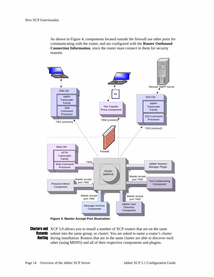
Figure 4 illustrates the use of Master Accept Port 7400. The router accepts connections on port 7400 from all components. During XCP configuration, the use of the Master Accept Port removes the necessity of specifying router connection information separately for each component that connects to the router.
If, however, you want to configure a component so that the router connects to it, each component’s configuration screen gives you the Router Outbound Connection Information option as shown below. This option is disabled by default in the component configuration screens, and you must enable and configure it if you want the router to connect to the component.
Figure 3. Router Outbound Connection
Jabber XCP 5.1 Configuration Guide Overview of the Jabber XCP Server Page 13
New XCP Functionality
As shown in Figure 4, components located outside the firewall use other ports for communicating with the router, and are configured with the Router Outbound Connection Information, since the router must connect to them for security reasons.
Figure 4. Master Accept Port illustration
Clusters and Dynamic Routing
XCP 5.0 allows you to install a number of XCP routers that are on the same subnet into the same group, or cluster. You are asked to name a router’s cluster during installation. Routers that are in the same cluster are able to discover each other (using MDNS) and all of their respective components and plugins.
Web CM
HTTPTranscoder
Family
Web CommandProcessor
Presence MirrorComponent
Router(jabberd)
Message ArchiverComponent
Jabber UserDirectory
Component
Text ConferencingComponent
JSM CM
S2S CM
Firewall
XMPPTranscoder
Family
JSMCommandProcessor
XMPPTranscoder
Family
S2S CommandProcessor
Jabber SessionManager Plugin
Master acceptport 7400
7400
7301 (connect)
7310 (connect)
Remote XMPP Server
File TransferProxy Component
7358 (connect)
file
Master acceptport 7400
Master acceptport 7400
Master acceptport 7400
Page 14 Overview of the Jabber XCP Server Jabber XCP 5.1 Configuration Guide

New XCP Functionality
For example, let’s say that four routers have been installed in the same cluster, MainCluster (as illustrated in Figure 5). Each router knows about the other routers because they belong to the same cluster. When the Text Conferencing component on Router 4 comes online, Router 4 sends the component’s presence to all of the other routers, and the routing table on each router is dynamically updated. Therefore, if one of the routers goes down, another route can be found.
To make things more interesting, SDNS is being used on each router to spread the conferencing load across the four TC components. Through the dynamic routing feature, all ports that are necessary for SDNS communication between these components are dynamically configured for you. You no longer need to laboriously configure the Jabberd Port as was required in the previous release.
Figure 5. Cluster and Dynamic Routing illustration
Router-to- Router
Connection
The Router-to-Router Connection component allows a connection between two routers that are not in the same cluster. This component must be configured on the router that is initiating the connection.
TextConferencing
TC-1.r1
TextConferencing
TC-1.r3
TextConferencing
TC-1.r4
SDNSconf.jabber.com
SDNSconf.jabber.com
SDNSconf.jabber.com
Router1realm=r1
SDNSconf.jabber.com
TextConferencing
TC-1.r2
Router2realm=r2
Router3realm=r3
Router4realm=r4
MainCluster
Jabber XCP 5.1 Configuration Guide Overview of the Jabber XCP Server Page 15
The Jabber XCP Controller
The Jabber XCP ControllerThe Jabber XCP Controller is a web-based administration console through which you configure the server’s central router, router plugins, and components. The Controller’s main screen is shown below; it provides information about the core Jabber XCP server, and all plugins and components installed on the server. You can start and stop the server and its components from this location. You can also view an XML summary of your server configuration. The main screen is divided into four areas: Configuration View, System, Router, and Components.
Caution: Jabber, Inc. recommends that you use the Controller to configure the Jabber XCP server rather than attempting to edit the XML configuration files manually. If you edit the files manually, your configuration could easily become compromised. Furthermore, if you hand-edit a component’s XML file, you cannot use the Controller later to edit the component’s configuration.
Page 16 Overview of the Jabber XCP Server Jabber XCP 5.1 Configuration Guide

The Jabber XCP Controller
Figure 6. Jabber XCP Controller main screen
Configuration ViewsThe Jabber XCP Controller offers three modes of configuration, called “Configuration views”: Basic, Intermediate, and Advanced. The following figure shows the “Configuration view” drop-down menu, which is located in the top right corner of every Controller screen. When you select a particular view, it remains in effect on all screens until you change it.
Figure 7. Configuration views
Jabber XCP 5.1 Configuration Guide Overview of the Jabber XCP Server Page 17

The Jabber XCP Controller
The Basic configuration view uses default values for the most part, and displays the fewest configuration options. Configuring your system using this mode enables you to get your Jabber XCP system up and running in the shortest amount of time.
The Intermediate configuration view provides all of the options that are available in the Basic view in addition to some other options, such as those used for hostname and command configurations, and for logging. It also includes many of the options for components that are installed with the Jabber XCP Developer Extensions. The components whose configurations require you to use at least the Intermediate view include:
• Information Broker• Message Archiver• Presence Mirror• Wait List Service• Web Services
Finally, the Advanced configuration view provides all of the Controller’s configuration options, including those used for detailed router configuration. This view is also required for configuring the Single Domain Name Support (SDNS) and Router-to-Router components, two of the server’s most advanced features. The Advanced configuration view also lets you configure options such as buffer sizes, thread counts, run levels, and custom loggers. These options require a more advanced level of XCP server knowledge and can be used for fine tuning your XCP system.
Areas on the Main ScreenThe areas on the Controller’s main screen are described in the following sections.
The System Area
The System area contains a Summary link that lets you display the complete jabber.xml file containing your configuration settings, a Cluster link that allows you to access all of the Controllers for this cluster, and a Stop the System link that allows you to stop the Jabber XCP system. It also provides a Window Help link that displays a help topic for the Controller’s main screen, and a Full Help System link that opens the entire online help system.
If you have modified the configuration of a plugin or component, you must restart the system before the changes take effect and before they display in the Summary.
Figure 8. System area on Controller’s main screen
Page 18 Overview of the Jabber XCP Server Jabber XCP 5.1 Configuration Guide

The Jabber XCP Controller
To stop the server, click the Stop the System link. The XCP server stops, and all associated components and plugins also stop. The following screen displays:
Figure 9. Restart the server link
To restart the server, click the start the server now link.
Click view all of the controllers to access the screen from which you can access all of the Controllers in the current cluster.
The Router Area
Router plugins are extensions to the server’s core router, jabberd, and always start and stop with the system. The Router area of the Jabber XCP Controller is where you add, modify, or remove router plugins.
Figure 10. Router area on Controller’s main screen
Each plugin on your system is listed in the Router area. You will always find a “Core Router” plugin in the table. The core router cannot be removed from the server. As you add other plugins, they are listed in the table as well.
You add a new plugin by selecting one in the drop-down list and clicking the Go button to access its configuration window. You can also modify an existing plugin’s configuration by clicking the corresponding Edit link, or remove a plugin (except for the core router) by clicking its Remove link.
Jabber XCP 5.1 Configuration Guide Overview of the Jabber XCP Server Page 19

Configuration Guidelines
The Components Area
Components are extensions of the Jabber XCP server that can be started and stopped independent of the server. The Components area, shown in the following figure, is where you add, modify, start, stop, or remove server components.
Figure 11. Components area on Controller’s main screen
You add a new component by selecting one in the drop-down list and clicking the Go button to access its configuration window. You can start and stop individual components if needed by clicking the Start and Stop links. You can also modify an existing component’s configuration by clicking the corresponding Edit link, or remove a stopped component by clicking its Remove link. (You must stop a component before you can remove it.)
The Components area is organized by host. That is, all components installed on a particular host are listed together in the table.
Online HelpOnline help is provided for each configuration window through a Help link; the help topic that displays contains detailed descriptions of the parameters required for configuring the plugin or component.
Configuration GuidelinesWhen you install Jabber XCP, a default connection manager with a Web command processor is installed on your system to give you access to the Jabber XCP Controller through a Web browser. You must use the Controller to modify the default configurations for the Jabber XCP system components and plugins, and to add, remove or reconfigure the components and plugins associated with your system.
A configuration manager, which is part of the jabberd, handles the validation, storage and retrieval of configuration data for the router and all of its components. All component configuration information is stored with the configuration manager.
Page 20 Overview of the Jabber XCP Server Jabber XCP 5.1 Configuration Guide

Configuration Guidelines
We recommend that you use the Jabber XCP Controller to configure and to make all necessary modifications to your Jabber XCP system. The Controller ensures that all parameters are configured properly and that all parts of the system work together correctly.
Optimal Network ConfigurationIn order to run an efficient and secure Jabber deployment, it is important to correctly configure your network for integration with the Jabber XCP server. Here are several principles to keep in mind when deploying a Jabber system:
• In general, a Jabber XCP server should be treated similarly to any other major piece of infrastructure, such as a web server or e-mail server.
• If your Jabber deployment is intended solely for internal use within your organization, it should not be exposed outside your organization’s firewall.
• If your Jabber deployment is accessed by both internal and external users, you may need to open selected ports in your firewall (see below). You may even want to run two Jabber servers: one within the firewall (for internal users) and one outside the firewall (for external users), with server-to-server communication set up between them.
• Jabber uses persistent TCP sockets between clients and the server, as well as from one server to another. Therefore, make sure that any firewalls have appropriate time-outs so that connections are not lost unnecessarily.
• When you are configuring your Jabber server, use a static IP address and not DHCP.
Firewall ConsiderationsThe optimum firewall configuration for your deployment depends on your organization’s requirements and security policies. If your Jabber server accepts TCP connections only from users within your organization’s firewall, you do not need to open any additional ports. In certain situations (for example, if your organization has employees who telecommute), you may want to use the standard Jabber client port 5222 with TLS so that users outside the firewall can make incoming connections to your server. In addition, if you would like users of your server to communicate with users of an external server, you must open the standard Jabber server port 5269 to enable server-to-server connections.
Jabber XCP 5.1 Configuration Guide Overview of the Jabber XCP Server Page 21

Configuration Guidelines
A more complex configuration would have one server behind the firewall for internal users, one server outside the firewall for external users, and a trusted server-to-server channel between the two servers over port 5269 (with “white listing” at the firewall level to open server-to-server communications over port 5269 only between these two machines).
By default, components are configured to use the accept (or passive) connection type. With this connection type, the server listens for a connection from the component. This connection is considered passive because the server waits passively for the component to connect to it. Conversely, if you select the connect (or active) connection type when you configure the component, the server actively connects to the component.
To avoid firewall interference with a connection, you should also set a keep-alive interval when you configure the component. The keep-alive helps prevent firewalls from dropping an unused connection to the component.
Hardware ConsiderationsFor a base-level deployment (up to 5,000 users), it is usually sufficient to run both the core server and a connection manager (CM) on one machine. Somewhat larger, “scale 1” deployments (up to 20,000 users) will probably want to add several machines, each running its own CM to complement the machine running the core server. A separate machine running external components such as Text Conferencing may also be desirable, though not strictly necessary. Larger, “scale 2” deployments (more than 20,000 users) may need to take advantage of Jabber servers in multiple locations and implement specialized features for high availability. For assistance regarding large deployments, we recommend that you discuss your requirements with representatives from Jabber, Inc.
Page 22 Overview of the Jabber XCP Server Jabber XCP 5.1 Configuration Guide

Chapter 2. Advanced File Transfer
The Advanced File Transfer (AFT) feature allows users to transfer files via HTTP, and stores transaction information associated with each file transfer in a database. AFT is used mainly by customers who want to monitor, archive, and log their users’ file transfer activities, say for example, to comply with SEC laws. This feature is more robust than the File Transfer Proxy component that was included beginning in XCP 4.x, and can be used in place of it.
When a user uploads a file for transfer, it is placed in a staging area and scanned. If the scan is successful, the file is archived, and a URL from which the file can be downloaded is sent to the user who uploaded the file. This user sends the URL to other users who can then download the file. When a user downloads the file, a copy of the file is sent from the archive to the user, and the transaction is recorded in the database.
The following sections are provided in this chapter:
• Architectural Overview• Configuring the Advanced File Transfer Handler• Configuring an Open Port• HTTP File Transfer Protocol
Jabber XCP 5.1 Configuration Guide Advanced File Transfer Page 23

Architectural Overview
Architectural OverviewFigure 12 illustrates the flow of data through the AFT Handler for files being transferred.
Figure 12. Advanced File Transfer architecture
Connection Manager
HTTP DirectorFamily
WebCP
AFT Handler
OpenPortComponent
Upload file viaHTTP POST
Postgresor Oracle
Record AllTransactions
Router(jabberd)
file
ReceiveURL
URL
Download Filevia HTTP GETNotify contacts
of URL
URL
URL
Step 3.
Step 1.
Step 4.
Step 2. file
file
Page 24 Advanced File Transfer Jabber XCP 5.1 Configuration Guide
Configuring the Advanced File Transfer Handler
Configuring the Advanced File Transfer HandlerYou configure the Advanced File Transfer Handler as part of the Web Command Processor (WebCP) within a Connection Manager (CM). Although you can add the AFT Handler to an existing CM that is configured with a WebCP, we recommend that you configure the handler in its own CM so that the CM can be dedicated exclusively to transferring files.
To configure the Advanced File Transfer Handler
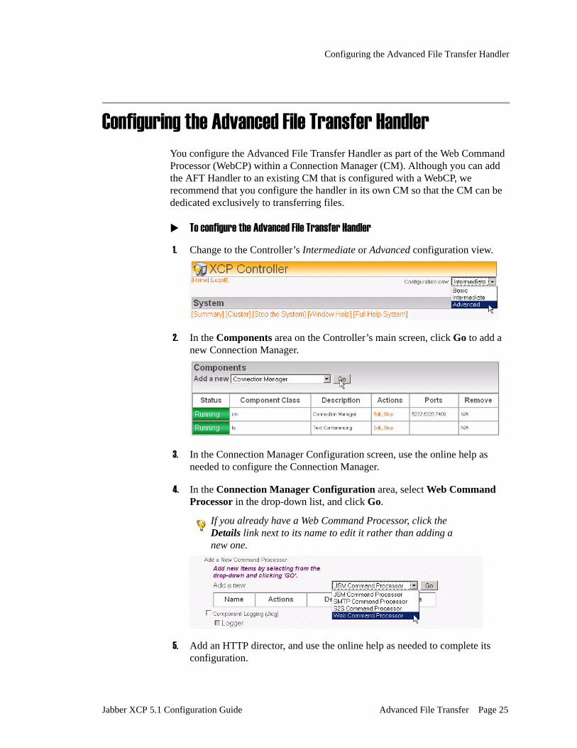
1. Change to the Controller’s Intermediate or Advanced configuration view.
2. In the Components area on the Controller’s main screen, click Go to add a new Connection Manager.
3. In the Connection Manager Configuration screen, use the online help as needed to configure the Connection Manager.
4. In the Connection Manager Configuration area, select Web Command Processor in the drop-down list, and click Go.
If you already have a Web Command Processor, click the Details link next to its name to edit it rather than adding a new one.
5. Add an HTTP director, and use the online help as needed to complete its configuration.
Jabber XCP 5.1 Configuration Guide Advanced File Transfer Page 25

Configuring the Advanced File Transfer Handler
If you are editing an existing WebCP that already has an HTTP director, you do not have to add another director.
6. In the WEBCP Configuration area on the Web Command Processor Configuration screen, click Go to add an Advanced File Transfer Handler.
7. The upper portion of the Advanced File Transfer Handler Configuration screen is shown in the following figure using the Controller’s Advanced configuration view. Change the configuration parameters as needed using the descriptions provided in the following table.
The parameters are described as follows:
Parameter Description
Connection Type With a connect connection type, the router connects to the handler.
With an accept connection type, the router opens a specific port and listens on that port for a connection from the handler. By default, the router uses the accept method to listen for connections from all components.
Component IP For a connect connection type, enter the IP address or hostname of the system on which the AFT handler’s CM is installed.
For an accept connection type, enter the IP address or FQDN on which the router listens for the AFT handler.
Page 26 Advanced File Transfer Jabber XCP 5.1 Configuration Guide

Configuring the Advanced File Transfer Handler
8. A database is required for the Advanced File Transfer handler. If you configured a database for the Core Router in the Global Settings Configuration screen, you do not have to configure one here. However, if you did not configure a global database or want to use a different database for AFT, select the Database Setup option and configure the parameters.
The parameters are described as follows:
Port For a connect connection type, enter the port that the handler uses for communications.
For an accept connection type, enter the port on which the router listens for the handler’s connection. The router allows only a single connection over this port at a time; therefore, multiple versions of the handler cannot connect over the same port.
Password Enter the password that the router uses to authenticate the component.
Number of threads to use for HTTP file transfers
Enter the number of threads that you want the AFT handler to use for processing HTTP file transfers.
HTTP URI Paths Handled
This option displays only in the Controller’s Advanced configuration view.
The HTTP URI Path is simply a prefix that the WebCP uses to determine what handler to use for a particular HTTP request. The default path for this handler is /files.
Parameter Description
Datasource name For the PostgreSQL database, this is the name of the datasource as specified in the .odbc.ini file. For Oracle, the datasource is specified in the ORACLE_SID environment variable or in the tsnames.ora file. For DB2, this is typically the database alias.
Database user name Enter the username used to connect to the database.
Parameter Description
Jabber XCP 5.1 Configuration Guide Advanced File Transfer Page 27

Configuring the Advanced File Transfer Handler
9. Configure the following parameters.
The parameters are described as follows:
Database user’s password
Enter the password used to connect to the database.
Confirm password Enter the password again to confirm it.
Database type Select the type of database you are using from the drop-down list.
Important! If you select postgresql-odbc, you must add the line, “MaxVarcharSize=4000” to the datasource definition in the .odbc.ini file.
Number of connections to the database
Enter the number of connections that you want this handler to use for processing requests.
Time in seconds between database connection heartbeats
Enter the number of seconds after which the database connection should refresh. Do not set this value to 0 without contacting Jabber support.
Is database debug logging enabled?
This option displays only in the Controller’s Advanced configuration view.
Select Yes to log database debug information.
Database logging uses jabberd’s logging facility. The Jabberd logger must be set to DEBUG for database logging to occur.
Parameter Description
Maximum file size (in bytes)
Enter the maximum-size file that can be transferred. ‘0’ means the file size is unlimited (the OS maximum file size, which is typically 4 GB).
Host name This is the host filter of the AFT handler. The default host filter simply adds “aft.” onto the beginning of the XCP server’s host name.
Important! This host name must be specified in the Host Filter text field in the AFT’s Open Port configuration.
Parameter Description
Page 28 Advanced File Transfer Jabber XCP 5.1 Configuration Guide

Configuring the Advanced File Transfer Handler
10. Select the scanning program option if you want to scan all files that are uploaded for transfer. Enter the absolute path to the scanning program; for example, /usr/bin/clamscan.
If you choose not to enable a scanning program, uploaded files are sent directly to the archive directory.
11. Click Submit to save your configuration.
For the Windows XCP server, 16-bit scanning applications are not supported. Only 32-bit scanning applications are supported.
Base URL of Advanced File Transfer handler
This is the URL that clients will use to connect to the AFT handler. The host portion of this URL must be resolvable in DNS.
Important! You must make sure that the HTTP director’s port number is appended onto the end of this URL; for example:http://aft.corp.example.com:7335
7335 is the default setting. If this is incorrect, you must change it.
Absolute path of the staging directory
The absolute path to the directory in which uploaded files will be staged temporarily while they are being scanned. This directory must already exist, and should be located on the same machine on which the AFT CM is installed.
Absolute path of the archive directory
The absolute path to the directory in which files that are successfully scanned will be archived. This directory must already exist and should be located on the same machine on which the AFT CM is installed.
Parameter Description
Jabber XCP 5.1 Configuration Guide Advanced File Transfer Page 29

Configuring an Open Port
Configuring an Open PortIn addition to providing the information in the Advanced File Transfer Handler Configuration screen, you must configure an Open Port component to enable the AFT Handler to connect to the router.
To configure the open port
1. In the Components area on the Controller’s main screen, select OpenPort from the drop-down list, and click Go.
2. When prompted for an ID for the open port, enter the ID of the AFT Handler and click OK.
3. In the OpenPort Configuration screen, change the description to something like AFT Open Port.
4. The open port must use a connection type that is opposite the one specified for the AFT Handler. By default, the AFT Handler’s connection type is set to connect, and the open port’s connection type is set to accept (using the Master Accept Port configure for the core router).
If you need to change the open port’s connection type to connect, select the Router Outbound Connection Information option, and specify the same component IP, port, and password that you used for the AFT handler.
Page 30 Advanced File Transfer Jabber XCP 5.1 Configuration Guide

HTTP File Transfer Protocol
5. In the open port’s Hostnames for this Component text field, enter the AFT handler’s hostname; for example, aft.corp.example.com.
6. Click Submit to save your configuration. Click Submit in the Web Command Processor and Connection Manager screens as well.
7. Restart your system.
HTTP File Transfer ProtocolThis section describes the basic protocol and flow for an HTTP file transfer server.
IntroductionThe XCP now includes a CM-based HTTP server that enables a more controlled form of file transfer than the usual peer-to-peer model (such as the one used for the File Transfer Proxy component). Since the server MUST be used during the process, it can maintain a central archive of all files transferred within an organization. All files uploaded to the server can be logged and approved (for example, scanned for viruses and/or sensitive information) before being made available to the recipient(s). Additionally, all downloads of the file are also logged, providing a complete history of a file’s access and lifetime. In order to ensure the identities of the file sender and recipients, each action is authenticated using an in-band XMPP protocol (Authenticating HTTP via Jabber [1]).
RequirementsAll files uploaded to the system MUST be logged and scanned before becoming available for download. If either task fails the file will not be retrievable. Likewise, all downloads MUST be logged before the file is sent to a recipient. All logging will occur in a RDBMS.
Jabber XCP 5.1 Configuration Guide Advanced File Transfer Page 31

HTTP File Transfer Protocol
The transfer component will scan files using a external program that is provided by the XCP administrator. When invoked, the program should analyze the file and simply return success or failure. In the latter case, the file is purged from the staging area and is not made available for download.
The interface to the external scanner program is two command-line arguments and a return code of success (0) or failure (non-zero). In the following example each of the strings is replaced with the corresponding value.
Example 1. External Scanner Interface <absolute-program-path> <file> <uploader-jid>
Process Use CasesThe following use cases and examples will show the general sequence of a file transfer.
Service Discovery
Before a file can be uploaded, the file sender must determine that the functionality is supported using “Service Discovery [2]”. In addition, the sender must know what URL to use for uploading the file. This extra information is communicated using “Service Discovery Extensions [3]”.
Example 2. Disco Identity <iq type='get' to='http_xfer.isis.corp.jabber.com' from='[email protected]/Bass'> <query xmlns='http://jabber.org/protocol/disco#info'/> </iq>
<iq from='http_xfer.isis.corp.jabber.com' id='jcl_9' to='[email protected]/Bass' type='result'> <query xmlns='http://jabber.org/protocol/disco#info'> <identity category='proxy' name='HTTP File Transfer' type='advanced-file-transfer'/> <feature var='http://jabber.org/protocol/disco#info'/> <feature var='http://jabber.org/protocol/http-auth'/> <feature var='http://jabber.com/schemas/advanced-file-transfer'/> <x type='result' xmlns='jabber:x:data'> <field var='URL' label='The URL used for the HTTP POST of the file'> <value>http://http_xfer.isis.corp.jabber.com/upload</value> </field> </x> </query> </iq>
The HTTP file transfer component responds to the disco#info with a few key pieces of information.
• The disco identity advertises “proxy” support of type “advanced-file-transfer”
Page 32 Advanced File Transfer Jabber XCP 5.1 Configuration Guide

HTTP File Transfer Protocol
• One of the supported features is “http://jabber.com/schemas/advanced-file-transfer”. This is also the XML namespace used for the container element used to carry information about the transferred file.
• The ‘jabber:x:data’ (Data Gathering and Reporting [4]) form contains the URL for the HTTP POST in a field called “URL”.
User Uploads File
The user uploads a file to the service using an HTTP POST request with the file contained in the request body. In the following HTTP example the string <file-bytes> refers to the contents of the file being uploaded. For more information about HTTP see “RFC 2616 [5]”.
Example 3. HTTP POST and authentication POST /upload HTTP/1.1 Authorization: x-xmpp-auth jid="[email protected]/Bass"
<file-bytes>
Note the use of the “x-xmpp-auth” scheme for authorization which is an authorization scheme that occurs over the XMPP band and is defined in “Authenticating HTTP via Jabber [6]”. In the above example the user has provided the JID in which the authentication iq should be sent. This JID MUST be a full JID (including a user and resource).
If the “x-xmpp-auth” scheme is not provided in the HTTP request the server will respond with an HTTP 401 (Unauthorized) error and a WWW-Authenticate header which informs the client that the “x-xmpp-auth” scheme MUST be used for authentication. The client may then resubmit the request with the proper credentials.
Example 4. HTTP 401 Unauthorized HTTP/1.1 401 Unauthorized WWW-Authenticate: x-xmpp-auth realm="xmpp"
File Sender Is Authenticated
Per “Authenticating HTTP via Jabber [7]” an iq packet is sent to the sender to authenticate the file upload request.
Example 5. IQ authentication <iq type='get' from='http_xfer.isis.corp.jabber.com' to='[email protected]/Bass' id='auth1'> <confirm xmlns='http://jabber.org/protocol/http-auth' method='POST' url='http://http_xfer.jabber.com/upload'/> </iq>
Upon receiving this iq from the server the client can confirm or deny that he/she is the user uploading the file.
Jabber XCP 5.1 Configuration Guide Advanced File Transfer Page 33

HTTP File Transfer Protocol
Example 6. Sender confirms upload <iq type='result' to='http_xfer.isis.corp.jabber.com' from='[email protected]/Bass' id='auth1'> </iq>
When the request is confirmed, the server allows the original POST to continue and the file is uploaded to the server. When the upload is complete, the server responds with an HTTP 201 (Created). The response body contains some additional information about the uploaded file; most importantly, the URL which recipients can use to download the file.
Example 7. Successful file upload HTTP/1.1 201 Created HTTPHeader: HeaderValue ...
<advanced-file-transfer xmlns='http://jabber.com/schemas/advanced-file-transfer'> <size-bytes>2360598</size-bytes> <url>http://http_xfer.jabber.com/files/xyz1234</url> </advanced-file-transfer>
The schema for the <advanced-file-transfer> element optionally allows for more information about the file, but in server responses, the URL and file size are the only values returned. Later, when the sending client messages the recipient more metadata SHOULD be sent.
If the client denies the confirmation the server responds to the original POST with a HTTP 403 (Forbidden).
Example 8. Sender denies upload <iq type='error' to='http_xfer.isis.corp.jabber.com' from='[email protected]/Bass' id='auth1'> <error code='401' type='auth'> <not-authorized xmlns='urn:ietf:params:xml:xmpp-stanzas'/> </error>` </iq>
Example 9. Server responds to denied upload HTTP/1.1 403 Forbidden
Sender Notifies Recipient(s)
When the sender receives notification that the file was successfully uploaded, the returned URL SHOULD be sent to other contacts in order to download the file. To carry the extra information about the file, the <advanced-file-transfer> element is used again.
Example 10. File transfer notification <message from='[email protected]/Bass' to='[email protected]/Drums'> <body> Les has sent you a file (A new for the upcoming album). You can download 'newtrack.mp3' from http://http_xfer.jabber.com/files/xyz1234 </body> <html xmlns='http://jabber.org/protocol/xhtml-im'> <body xmlns='http://www.w3.org/1999/xhtml'> Les has sent you a file (A new for the upcoming album).
Page 34 Advanced File Transfer Jabber XCP 5.1 Configuration Guide

HTTP File Transfer Protocol
You can download 'newtrack.mp3' from <a href='http://http_xfer.jabber.com/files/xyz1234'>here</a>. </body> </html> <advanced-file-transfer xmlns='http://jabber.com/schemas/advanced-file-transfer'> <filename>newtrack.mp3</filename> <size-bytes>2360598</size-bytes> <md5>7582e965bd800bd9bb28f4c4a8d2068f</md5> <mime-type>audio/mpeg</mime-type> <description>A new track for the upcoming album</description> <url>http://http_xfer.jabber.com/files/xyz1234</url> </advanced-file-transfer> </message>
The above example contains three child elements for maximum client portability. The traditional <body> and <html> elements is for clients that have no knowledge of HTTP file transfers, but that can display regular messages and/or XHTML messages. The <advanced-file-transfer> element targets clients that have specific knowledge of HTTP file transfer, and wish to build a message and/or GUI based on the file transfer metadata. What follows is a complete description of the <advanced-file-transfer> child elements.
• filename - The original file name. Note that the URL basename is a unique ID, not the original filename.
• size-bytes - A required element which specifies the size of the file.
• md5 - The MD5 checksum of the file.
• mime-type - The mime-type of the file.
• description - An optional description of the file.
• url - A required argument which specifies the URL where the file can be retrieved.
User Downloads File
The recipient client can fetch the file using a standard HTTP GET request.
Example 11. Recipient downloads file GET /files/xyz1234 HTTP/1.1 Authorization: x-xmpp-auth jid="[email protected]/Drums"
File Recipient Is Authenticated
Just as when the file was uploaded, the recipient must also be authenticated using x-xmpp-auth.
Example 12. IQ authentication <iq type='get' from='http_xfer.isis.corp.jabber.com' to='[email protected]/Drums' id='auth2'> <confirm xmlns='http://jabber.org/protocol/http-auth' method='GET' url='http://http_xfer.jabber.com/files/xyz1234'/> </iq>
Jabber XCP 5.1 Configuration Guide Advanced File Transfer Page 35
HTTP File Transfer Protocol
Security ConsiderationsAs previously stated, all actions on a particular file MUST be logged in a RDBMS before the action is granted. The address and port used by the HTTP file transfer server MAY need to have special firewall access.
IANA ConsiderationsThere are no know IANA consideration pertaining to this IJEP.
Jabber Registrar ConsiderationsThe Jabber Registrar shall be updated to contain the following URIs and identifiers:
• advanced-file-transfer - The disco identity type value for HTTP file transfer components.
• http://jabber.com/schemas/advanced-file-transfer - The namespace for advanced-file-transfer elements.
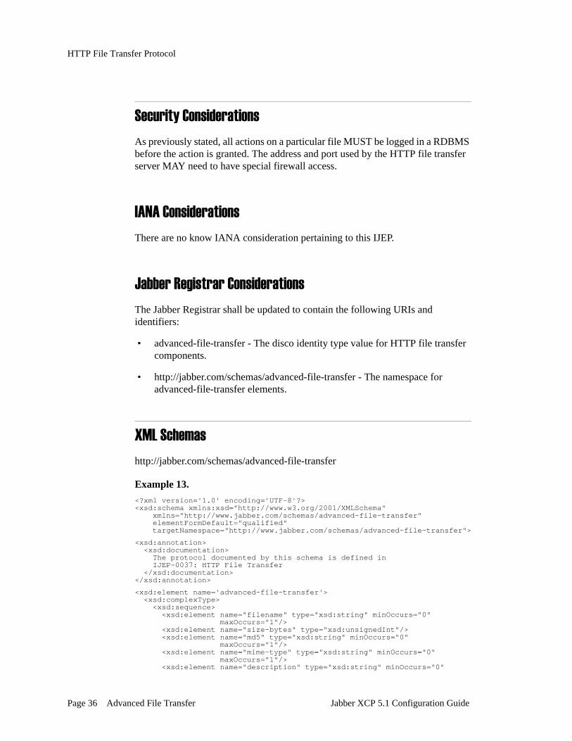
XML Schemashttp://jabber.com/schemas/advanced-file-transfer
Example 13.<?xml version='1.0' encoding='UTF-8'?><xsd:schema xmlns:xsd="http://www.w3.org/2001/XMLSchema" xmlns="http://www.jabber.com/schemas/advanced-file-transfer" elementFormDefault="qualified" targetNamespace="http://www.jabber.com/schemas/advanced-file-transfer">
<xsd:annotation> <xsd:documentation> The protocol documented by this schema is defined in IJEP-0037: HTTP File Transfer </xsd:documentation></xsd:annotation>
<xsd:element name='advanced-file-transfer'> <xsd:complexType> <xsd:sequence> <xsd:element name="filename" type="xsd:string" minOccurs="0" maxOccurs="1"/> <xsd:element name="size-bytes" type="xsd:unsignedInt"/> <xsd:element name="md5" type="xsd:string" minOccurs="0" maxOccurs="1"/> <xsd:element name="mime-type" type="xsd:string" minOccurs="0" maxOccurs="1"/> <xsd:element name="description" type="xsd:string" minOccurs="0"
Page 36 Advanced File Transfer Jabber XCP 5.1 Configuration Guide

HTTP File Transfer Protocol
maxOccurs="1"/> <xsd:element name="url" type="xsd:anyURI"/> </xsd:sequence> </xsd:complexType></xsd:element></xsd:schema>
Notes1. JEP-0070: Authenticating HTTP via Jabber
<http://www.jabber.org/jeps/jep-0070.html>
2. JEP-0030: Service Discovery <http://www.jabber.org/jeps/jep-0030.html>
3. JEP-0128: Service Discovery Extensions <http://www.jabber.org/jeps/jep-0128.html>
4. JEP-0004: Data Gathering and Reporting <http://www.jabber.org/jeps/jep-0004.html>
5. RFC 2616: Hypertext Transport Protocol -- HTTP/1.1 <http://www.ietf.org/rfc/rfc2616.txt>
6. JEP-0070: Authenticating HTTP via Jabber <http://www.jabber.org/jeps/jep-0070.html>
7. JEP-0070: Authenticating HTTP via Jabber <http://www.jabber.org/jeps/jep-0070.html>
Jabber XCP 5.1 Configuration Guide Advanced File Transfer Page 37

HTTP File Transfer Protocol
Page 38 Advanced File Transfer Jabber XCP 5.1 Configuration Guide

Chapter 3. Logging
The Jabber XCP server provides a number of different logging options. By default, the server’s core router, jabberd, is configured to log JSM and router data to syslog at the ‘info’ log level. You can change this default level as needed (as described in “Setting the Log Level for Router-Generated Packets”). Any level that you choose logs data at that level in addition to all the levels above it. For example, when the log level is set to ‘info’, data is logged at the ‘warn’ and ‘error’ levels as well.
The current jabberd log level is recorded in the jabber.loglevel file, which is located in $JABBER_HOME/var/tmp. This file is updated any time someone changes the log level and restarts the server.
If you require more logging than what occurs by default, you can configure the server to log statistics and other types of JSM data, and to use file and stderr loggers in addition to syslog. You can also configure syslog and stream loggers for each component.
Logging is an intermediate, and sometimes advanced, feature in the XCP Controller. When you configure Logging, make sure you are using the Controller’s Intermediate or Advanced configuration view.
The following sections are provided in this chapter:
• Configuring Syslog for Red Hat Linux• Setting the Log Level for Router-Generated Packets• Jabberd Logger Configuration• JSM Logging• Message Archiver Logging• Statistics Logging• Component Logging (Jlog)
Jabber XCP 5.1 Configuration Guide Logging Page 39

Configuring Syslog for Red Hat Linux
Configuring Syslog for Red Hat LinuxRed Hat Linux sets its syslog level to *.info by default, which means that it logs at the info, warn, and error levels (log levels are described in Table 1 on page 41). If you prefer to log information at lower levels as well, such as debug, you must edit the syslog configuration file on your Red Hat system, and set the syslog default to a value that is greater than or equal to the XCP log level that you plan to use.
To configure syslog
1. Change to the /etc directory on your Red Hat system.
2. Open the syslog.conf file in a text editor.
3. Locate the following lines:# Log anything (except mail) of level info or higher.# Don't log private authentication messages!*.info;mail.none;authpriv.none;cron.none /var/log/messages
4. To log all information in Syslog, add *.debug in the third line as shown below:*.info;*.debug;mail.none;authpriv.none;cron.none /var/log/messages
5. Save and close the syslog.conf file.
Setting the Log Level for Router-Generated PacketsThe log level specifies the severity of the data that is logged and determines the amount of data that the server records; the lower the severity level, the more verbose the log (see Table 1 for descriptions of severity levels). The core router is configured by default to log packets at the info level and above, which means that log packets are generated only for data that comes into the router at the ‘info’, ‘warn’, and ‘error’ levels.
The log level that is set for the core router is the level at which the server starts. If needed, you can temporarily change the level during runtime; however, the default level is restored when you restart the server.
Log levels are described in Table 1 and are listed in the order of decreasing severity. For example, the ‘warn’ log level is less severe than the ‘error’ log level. The lower the severity level, the higher the log’s level of verbosity.
Page 40 Logging Jabber XCP 5.1 Configuration Guide

Setting the Log Level for Router-Generated Packets
Table 1. Log severity levels
The log level must be set to ‘info’ or higher for the Jabber Session Manager (JSM) log types (message, packet, and session) to function properly. In addition, statistics data is not available if the log’s verbosity level is set below ‘info’.
To change the router’s default log level
1. In the Router area on the Controller’s main screen, click the Edit link for the Core Router.
2. In the Global Settings Configuration screen, expand the drop-down list beside Level of information to log, and select the desired level.
3. Scroll to the bottom of the screen and click Submit to save your configuration.
Severity Level Information logged...
error System-generated errors such as the inability to create listen ports, server configuration errors, failure to create the log files, etc.
warn All ‘error’ level data plus non-fatal errors such as bounced packets, nonexistent user logging in, invalid recipient for a message, etc.
info All ‘error’ and ‘warn’ level data plus information about socket connections and all JSM logs (packet, session, and message)
verbose All ‘error’, warn’, and ‘info’ level data plus every packet that is processed by the server and JSM.
debug All log-level data plus debug data.
Jabber XCP 5.1 Configuration Guide Logging Page 41

Jabberd Logger Configuration
To view the current log level
Enter the following command from the jabberInstallDir/bin directory: ./runjabber loglevel check
To increase the log’s verbosity level while the server is running
1. Enter the following command from the jabberInstallDir/bin directory to increase the log level by one increment (for example, from ‘warn’ to ‘info’).
./runjabber loglevel increase
2. Repeat the command for each desired level increase.
To decrease the log’s verbosity level while the server is running
1. Enter the following command from the jabberInstallDir/bin directory to decrease the log level by one increment (for example, from ‘info’ to ‘warn’).
./runjabber loglevel decrease
2. Repeat the command for each desired level decrease.
Jabberd Logger ConfigurationThe Jabberd Logger receives packets that are generated by the core router (jabberd), by JSM, and by any other plugin, and logs them to syslog, file, and/or stderr. The Jabberd Logger that is installed by default is configured to capture information generated in the generic namespace, jcs:log:default, and to log the information to syslog. You can edit the default logger, or you can add new ones. In the Jabberd Logger Configuration screen, you can select the namespaces for other types of information that you want to log, and you can specify the names of the hosts from which you want to log the information. You can also select the types of loggers that you want to use, and the log level(s) used to log the information.
You can configure multiple Jabberd Loggers depending on how specific you want to your logging to be. For example, if you want to log presence and session packets for host alpha.example.com to a file logger, and message packets for host beta.example.com to syslog, you would need to configure two Jabberd Loggers to handle the logging.
Page 42 Logging Jabber XCP 5.1 Configuration Guide

Jabberd Logger Configuration
To add a Jabberd Logger
1. In the Router area on the Controller’s main screen, select Jabberd Logger from the drop down list and click Go.
The Jabberd Logger Configuration screen opens as shown in the following figure.
2. Read the following sections for instructions on configuring the Jabberd Logger.
Jabber XCP 5.1 Configuration Guide Logging Page 43
Jabberd Logger Configuration
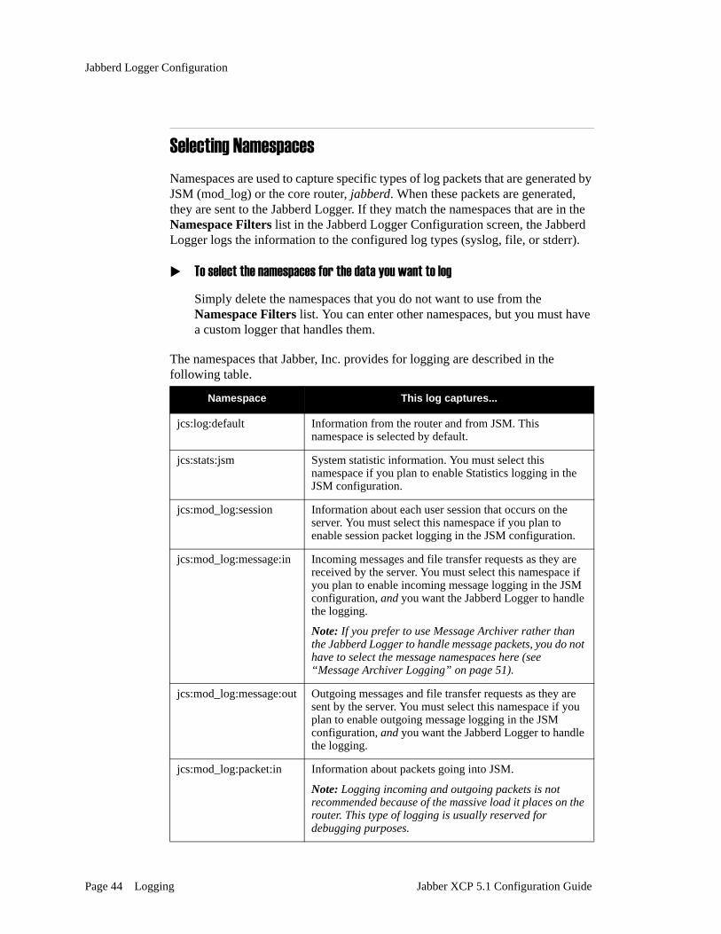
Selecting NamespacesNamespaces are used to capture specific types of log packets that are generated by JSM (mod_log) or the core router, jabberd. When these packets are generated, they are sent to the Jabberd Logger. If they match the namespaces that are in the Namespace Filters list in the Jabberd Logger Configuration screen, the Jabberd Logger logs the information to the configured log types (syslog, file, or stderr).
To select the namespaces for the data you want to log
Simply delete the namespaces that you do not want to use from the Namespace Filters list. You can enter other namespaces, but you must have a custom logger that handles them.
The namespaces that Jabber, Inc. provides for logging are described in the following table.
Namespace This log captures...
jcs:log:default Information from the router and from JSM. This namespace is selected by default.
jcs:stats:jsm System statistic information. You must select this namespace if you plan to enable Statistics logging in the JSM configuration.
jcs:mod_log:session Information about each user session that occurs on the server. You must select this namespace if you plan to enable session packet logging in the JSM configuration.
jcs:mod_log:message:in Incoming messages and file transfer requests as they are received by the server. You must select this namespace if you plan to enable incoming message logging in the JSM configuration, and you want the Jabberd Logger to handle the logging.
Note: If you prefer to use Message Archiver rather than the Jabberd Logger to handle message packets, you do not have to select the message namespaces here (see “Message Archiver Logging” on page 51).
jcs:mod_log:message:out Outgoing messages and file transfer requests as they are sent by the server. You must select this namespace if you plan to enable outgoing message logging in the JSM configuration, and you want the Jabberd Logger to handle the logging.
jcs:mod_log:packet:in Information about packets going into JSM.
Note: Logging incoming and outgoing packets is not recommended because of the massive load it places on the router. This type of logging is usually reserved for debugging purposes.
Page 44 Logging Jabber XCP 5.1 Configuration Guide

Jabberd Logger Configuration
Specifying Host FiltersIn the Host Filters text box, you can specify the names of hosts from which you want to log the selected packet types. For jcs:log:default packets, you should leave the asterisk (*), which will log packets in that namespace from all hosts. However, for other namespace filters you can either use the asterisk to indicate that you want to log these packet types from all hosts, or you can list specific hosts only.
Configuring Loggers and Log LevelsIn addition to the Syslog logger, which is enabled by default, you can configure a file logger and a standard error logger. In addition, you can select one or more log levels at which to log the information to these log types.
Syslog Logger The Syslog logger is enabled by default when you install the server. This logger logs information from the router, and from JSM and other plugins to syslog. Syslog refers to the logging daemon used to log messages generated by your operating system components. Syslog also provides log rotation based on file age and size. It can be run locally or remotely and does not require any additional hardware or software.
To configure the Syslog logger
1. Under Configuration on the Jabberd Logger Configuration screen, select the Details link beside the Syslog Logger. The Syslog Logger Configuration screen displays. (If you prefer, you can add a new Syslog logger rather than modifying the existing one.)
jcs:mod_log:packet:out Information about packets coming out of JSM.
jcs:mod_log:presence Information about client users’ presence. You must select this namespace if you plan to enable presence packet logging in the JSM configuration.
Namespace This log captures...
Jabber XCP 5.1 Configuration Guide Logging Page 45

Jabberd Logger Configuration
2. Configure the Syslog logger using the online help as needed for field descriptions.
3. Click Submit to save your configuration.
File Logger The File Logger lets you specify the name and location of a log file and various parameters for the information that you want to log to it.
To configure the File logger
1. Under Configuration on the Jabberd Logger Configuration screen, select File Logger from the drop-down list, and click Go. The File Logger Configuration screen displays.
2. Configure the File logger using the online help as needed for field descriptions.
3. Click Submit to save your configuration.
Standard Error Logger
The Standard Error Logger lets you format information that is logged to stderr.
To configure the Standard Error logger
1. Under Configuration on the Jabberd Logger Configuration screen, select Standard Error Logger from the drop-down list, and click Go. The Standard Error Logger Configuration screen displays.
2. Enter the log formatters for the type of information that you want logged. (See “Formatting Logs” on page 47 for more information.)
3. Click Submit to save your configuration.
Page 46 Logging Jabber XCP 5.1 Configuration Guide

Jabberd Logger Configuration
Log Levels You can select one or more log levels, which pertain to all of the loggers configured in this particular instance of the Jabberd Logger plugin.
To select one or more log levels
1. Under Configuration on the Jabberd Logger Configuration screen, select Standard Log Levels from the drop-down list, and click Go. The Log Levels Configuration screen displays.
2. Select one or more log levels in the list (hold down the CTRL key to select more than one). The logs you have selected for this particular Jabberd Logger configuration will each log at these levels.
3. Click Submit to save your configuration.
Formatting LogsYou can modify how log information is formatted using a number of attribute codes.
To format a log
Add any or all of the attribute codes listed in the table below in a logger’s Format textbox to capture the desired data in your log.
Format Tag Description
%h The point in the code where the log message was generated. In general, this information is useful in debugging the server. It is usually not useful when used with message and session logs.
%i The thread number inside the server that generates the log message; used for debugging.
%s The information being logged.
%d The Greenwich Mean Time and date when the log message was generated.
Jabber XCP 5.1 Configuration Guide Logging Page 47

JSM Logging
JSM LoggingIf you want to log message, session, and presence packets in addition to the JSM-generated packets logged by the server by default, you can configure this logging in the Jabber Session Manager Configuration screen.
To configure JSM logging
1. In the Router area on the Controller’s main screen, click the Edit link for the Jabber Session Manager.
2. In the Jabber Session Manager Configuration screen, scroll down to the JSM Logging section, and click the checkbox to enable it. (The Advanced configuration view is shown in the following figure.)
In the Controller’s Intermediate view, you can enable the logging of incoming and outgoing message packets. In the Advanced view, you can additionally enable the logging of session and presence packets, and of summarized packets.
3. Select Yes beside any of the packets that you want to log. Use the online help as needed to complete the logging configuration.
4. Click Submit to save your configuration. You are returned to the Controller’s main screen.
%t The log level of the message; for example, none, error, info, warn, verbose, debug. This attribute does not work with message, packet, or session logs.
Format Tag Description
Page 48 Logging Jabber XCP 5.1 Configuration Guide

JSM Logging
5. Edit the Jabberd Logger plugin.
6. In the Jabberd Logger Configuration screen, select the namespaces in the Namespace Filters list that correspond to the packet types you selected for JSM logging. (Hold down the CTRL key to select multiple namespaces.) Packets generated by JSM in these namespaces will be logged to the loggers that you have configured for the Jabberd Logger. The namespaces correspond to the packets in the JSM Configuration screen as follows:
7. Click Submit to save your configuration.
8. Restart your system.
The following sections describe packet, session, and message logs.
Jabberd Logger namespaces JSM packet types
jcs:mod_log:session Session Packets
jcs:mod_log:message:in Incoming message packets
jcs:mod_log:message:out Outgoing message packets
jcs:mod_log:packet:in Summarized packet data
jcs:mod_log:packet:out Summarized packet data
jcs:mod_log:presence Presence packets
Jabber XCP 5.1 Configuration Guide Logging Page 49

JSM Logging
Packet LogsPacket logs contain two types of data: non-IQ packets and IQ packets. A non-IQ packet records whether the packet contained an IQ packet (designated by ‘i’), presence information (designated by ‘p’), or subscription information (designated by ‘s’). Non-IQ packet information resembles the following:
An IQ packet contains all of the information that is saved for the non-IQ packet. It also includes a numeric sub-type for the packet and the namespace from which the data came. Numeric sub-types include: 5 for ‘get’; 6 for ‘set’, and 7 for ‘result’. IQ packet log information resembles the following:
Session LogsSession logs contain information about each user session that occurs on the server. When the user logs off or is disconnected, the server logs the timestamp of when the session ended, the number of seconds the session lasted, and the full Jabber ID of the user associated with the session (for example, user@host/resource). It also records the number of packets sent and received.
The session log provides information only after a session has ended, and therefore does not provide information about a user’s session while that user is logged in.
<log time='20060128T18:16:32'>p [email protected]/resource [email protected]/0.8.5 98</log>
JID to which the packet was sent Size of the packet in bytes
JID from which the packet was sent
’p’ indicates presence datalog date and time
<log time='20020128T18:16:32'>i [email protected]/resource - 101 5 jabber:iq:roster</log>
The JID to which the packet was sent. A dash indicates that the packet went to the server.
'i' indicates an IQ packet log
IQ packet namespace
Size of the packet in bytes
‘5’ indicates a 'get' sub-type
Page 50 Logging Jabber XCP 5.1 Configuration Guide

Message Archiver Logging
Session log information resembles the following:
Message LogsMessage logs contain all messages. You may want to use the message log feature to archive your message traffic. You may archive traffic through the server by writing the message logs to a file and backing them up outside of the server.
Message log information resembles the following:
Message Archiver LoggingYou can send all inbound and outbound message packets to the Message Archiver component for logging instead of, or in addition to, the Jabberd Logger. Message Archiver handles the message packets and stores them in PostgresSQL or in Oracle. (If you do not select the message namespaces in the Jabberd Logger configuration, message packets will be logged only through Message Archiver as long as you have configured a Message Archiver component.)
<log time='20030528T18:19:26'>174 1 5 [email protected]/resource</log>
The time and date the user logged out
Length of session in seconds
Number of packets received
Number of packets sent
JID whose session is recorded here
<log time='20030628T18:18:52'><message to='[email protected]' type='chat' from='[email protected]/resource'><body>How was the game?</body></message></log>
The time and date the message was sent
The entire message
Jabber XCP 5.1 Configuration Guide Logging Page 51

Message Archiver Logging
To log message packets through Message Archiver
1. In the Components area on the Controller’s main screen, select Message Archiver in the drop-down list, and click Go to add a Message Archiver component.
2. Configure the Message Archiver component using the online help as needed.
3. In the Log area, select one or both namespaces in the Namespace Filters list depending on which message packets you want to log.
4. If you want to log message packets from specific hosts only, enter their hostnames or IP addresses in the Host Filters text box. The asterisk (*) is used to log message packets from every host.
5. Click Submit to save your configuration. You are returned to the Controller’s main screen.
6. Edit the JSM plugin.
7. In the Jabber Session Manager Configuration screen, scroll down to the JSM Logging section, and select the checkbox to enable the feature.
Page 52 Logging Jabber XCP 5.1 Configuration Guide

Statistics Logging
8. Select Yes for one or both message packet options. The packets you enable here should match the namespaces you selected in the Message Archiver configuration.
9. Click Submit to save your configuration.
10. Restart your system.
Statistics LoggingStatistics logging captures server statistics and logs the data to the log types that are configured for the Jabberd Logger. Statistics logging is turned off by default when you install the XCP server; however, you can enable it in the JSM configuration and set the time interval for capturing data.
Server statistics data includes the number of:
• Users who are currently online• Successful logins in the last time-slice interval• Successful logins since server startup• Failed logins since server startup• Offline messages stored in the last time-slice interval• Total messages since server startup• Presence packets since server startup• IQ packets since server startup
Statistics data also includes information about:
• The length of time, in seconds, that the server has been running• The average message size in the last time-slice interval• The number of messages in the last time-slice interval
To enable server statistics logging
1. In the Router area on the Controller’s main screen, add a new Jabberd Logger.
2. In the Jabberd Logger Configuration screen in the Namespace Filters list, remove all of the namespaces except for jcs:log:default and jcs:stats:jsm.
Jabber XCP 5.1 Configuration Guide Logging Page 53

Component Logging (Jlog)
3. Click Submit to save your configuration. You are returned to the Controller’s main screen.
4. In the Router area on the Controller’s main screen, click the Edit link for the Jabber Session Manager.
5. In the Jabber Session Manager Configuration screen, scroll down to the Stats section and click the checkbox to enable the option.
6. If needed, change the number of seconds that elapse before each capture of server statistics.
7. Scroll to the bottom of the Jabber Session Manager Configuration screen, and click Submit to save your configuration.
Component Logging (Jlog)All XCP components can log to the Jabber Logging Library, Jlog. Each component configuration screen has a Component Logging (Jlog) section, in which you can configure Syslog and stream loggers that filter the information based on the selected log level. The information that is logged varies by component.
The Syslog and stream loggers log information that is generated at or above the selected severity level and drops messages that are below that level. For example, if you select the warning level, warning and error messages are logged, and messages at the debug, verbose, and info levels are dropped.
Page 54 Logging Jabber XCP 5.1 Configuration Guide

Component Logging (Jlog)
When a component is daemonized, logging to stderr or stdout is disabled; if you start a component from the command line using the -P flag, it is daemonized.
To enable component logging, select the checkboxes beside Component Logging (Jlog) and Logger as shown below. Then select one or both logger types and configure them as needed.
Configuring the Filtered Syslog LoggerThe Filtered Syslog Logger logs component information to syslog at the selected level.
Jabber XCP 5.1 Configuration Guide Logging Page 55

Component Logging (Jlog)
To configure the Filtered Syslog Logger
1. Click the checkbox next to Filtered Syslog Logger to enable the options.
2. Select a severity level from the drop-down list.
3. Enter the full path to a pipe file for this component.
For UNIX and Linux, we suggest naming the file $JABBER_HOME/var/log/comp-id (where comp-id is the component’s ID). For Windows, we suggest naming the file \\.\pipe\comp-id, (where comp-id is the component’s ID). If the pipe file does not already exist on your system, it will be created.
You can send the file a pipe command of U (up) or D (down) to increase or decrease the amount of data being logged from the component. For example, if your log level is set to ‘verbose’ and you send a pipe command of D, the log’s level of verbosity is decreased to ‘info’.
You can also use the echo C > pipe_file command to create an entry in syslog indicating the current log level for the component. For pipe_file, enter the full or relative path (including the pipe file’s name) to the location of the component’s pipe file.
4. Select the facility that you want to use from the drop-down list. (Facilities are defined on the syslog(3) manpage.)
5. Enter a term that identifies where the log information is coming from. The identity is displayed in syslog next to the associated data. You can change the default value as needed.
6. Enter the formatters for the information that you want to log. (See “Formatting Logs” on page 47.)
7. When you have finished configuring the loggers, click Submit to save your configuration.
8. Restart your system.
Page 56 Logging Jabber XCP 5.1 Configuration Guide

Component Logging (Jlog)
Configuring the Filtered Stream LoggerThe Filtered Stream Logger logs information to stdout or to stderr at the selected level.
To configure the Filtered Stream Logger
1. Click the checkbox next to Filtered Stream Logger to enable the options.
2. Select a severity level from the drop-down list.
3. Enter the full path to a pipe file for this component.
For UNIX and Linux, we suggest naming the file $JABBER_HOME/var/log/comp-id (where comp-id is the component’s ID). For Windows, we suggest naming the file \\.\pipe\comp-id, (where comp-id is the component’s ID). If the pipe file does not already exist on your system, it will be created. (For more information about the pipe file, see Step 3 in the previous section.)
4. Select stderr or stdout from the drop-down list.
5. Enter the formatters for the information that you want to log. (See “Formatting Logs” on page 47.)
6. When you have finished configuring the loggers, click Submit to save your configuration.
7. Restart your system.
Jabber XCP 5.1 Configuration Guide Logging Page 57

Component Logging (Jlog)
Adding a New Custom LoggerIf you have created a custom logger for logging component information using the libjcore library, you can add it to your XCP server configuration. The custom logger option is available only in the Controller’s Advanced configuration view.
To add a custom logger
1. Click Go beside Add a new custom logger. The Custom Logger Configuration screen displays.
2. In the Custom library field, enter the library used for this logger.
3. In the Load field, enter the library entry point function.
4. Click Submit to save your configuration.
5. Restart your system.
Page 58 Logging Jabber XCP 5.1 Configuration Guide

Chapter 4. Server-to-Server
The Server-to-Server (S2S) feature enables Jabber XCP Servers to communicate with each other across domains. It also supports the Jabber dialback protocol, which determines whether or not to trust a connection from another server.
S2S enables you to configure the XCP server to:
• Blacklist IP addresses and hostnames to prevent unwanted server connections.
• Configure connections to expire automatically, and enforce connection lifetimes to ensure fair use of S2S delivery.
• Adjust the number of threads to manage performance, limit the maximum number of sockets used to manage resources and usage, and control the number of inbound/outbound bytes per second to manage resources and usage.
• Deliver messages with automatic retry if the remote server is unavailable. Each message delivery is attempted a configurable number of times before the message bounces back to the sender.
The S2S feature is configured as a Command Processor (CP) within a Connection Manager (CM). The S2SCP is configured by default with an XMPP Incoming Director and an XMPP Outgoing Director for XMPP server-to-server communications. These directors allow you to black- and white-list specific hosts that are internal and external to your environment. The Incoming director handles incoming packets being sent to the router from remote servers; the Outgoing director handles packets being sent from the XCP router to remote servers.
Jabber XCP 5.1 Configuration Guide Server-to-Server Page 59

Figure 13. S2S Connection Manager
S2S Connection Manager
S2S Command Processor
XMPP IncomingDirector
XMPP OutgoingDirector
XM
PP
InTr
ansc
oder
XMPP
Out
Tran
scod
er
Internet
Remote XMPPServer
OpenPortComponent
Router
Page 60 Server-to-Server Jabber XCP 5.1 Configuration Guide

As mentioned previously, you can configure S2S to blacklist hosts from sending or receiving packets. These hosts can be located either inside or outside of your Jabber XCP system. Figure 14 illustrates the handling of packets that are sent to or received from blacklisted hosts.
Figure 14. Packet handling for blacklisted hosts
CM
S2S
CP
XMPP IncomingDirector
XMPP OutgoingDirector
Blacklisted Host
Incoming packets
Outgoing packets
Packets sent to orreceived from blacklistedhostsCM
JSM
CP XMPP Director
Incomingpackets
Jabber Clients
The Incoming andOutgoing Directors do notforward packets that aresent to or received fromblacklisted hosts. Theseattempts are indicatedwith an 'x'.
Router(jabberd)
x
x
Network Cloud
Outgoingpackets
Remote Hosts
Blacklistedhost
Jabber XCP 5.1 Configuration Guide Server-to-Server Page 61

Configuring Server-to-Server
Configuring Server-to-ServerThe Server-to-Server functionality is configured as a command processor (CP) within a Connection Manager (CM). We recommend that you configure S2S within its own CM in order to maximize the efficiency with which the XCP server can handle S2S communication.
You can configure S2S using the Controller’s Intermediate configuration view.
To configure S2S
1. In the Components area on the Controller’s main screen, click Go to add a new Connection Manager.
2. Under Add a New Command Processor in the Connection Manager Configuration screen, select S2S Command Processor in the drop-down list, and click Go.
3. An outgoing director and an incoming director have been provided by default. The outgoing director handles packets that are being sent from the XCP router to remote servers. The incoming server director handles packets being sent to the router from remote servers.
Page 62 Server-to-Server Jabber XCP 5.1 Configuration Guide

Configuring an Open Port
4. If you want to specify which hosts and IP addresses may or may not send or receive packets, supply information for one or more of the following authorization options:
- Authorized Outgoing ‘From’ Addresses- Authorized Outgoing ‘To’ Addresses- Authorized Incoming ‘From’ Addresses- Authorized Incoming ‘To’ Addresses
See “Authorized Addresses” on page 66 for detailed descriptions of these options.
5. Three Outgoing Connection Attempt Rules have been provided by default. These rules specify the order and DNS lookup properties for each outbound director. By default, these three rules are configured with the ID of the XMPP Outgoing Server Director. However, if you add another director, you must edit the rules or add additional ones, and specify the ID of the director to which the rules apply.
6. If you require additional rules, click Go... (See “Outgoing Connection Attempt Rules” on page 65 for more information.)
Configuring an Open PortYou must configure an S2S Open Port component to enable the S2S Command Processor to connect back into the router with special rules (the * in the open port’s Host Filters field).
You must configure the Open Port using the Controller’s Intermediate configuration view or higher.
To configure the Open Port
1. In the Components area on the Controller’s main screen, select OpenPort in the drop-down list, and click Go.
Jabber XCP 5.1 Configuration Guide Server-to-Server Page 63

Configuring an Open Port
2. Enter the S2S Command Processor’s ID as the ID of the Open Port component; for example, cm-2_s2scp-1.
3. In the OpenPort Configuration screen, use the opposite connection type than that used for the S2SCP. If you configured the S2SCP with a connect connection type (the default setting), skip to Step 4.
However, if you configured the Command Processor with an accept connection type, you must enable Router Outbound Connection Information for the Open Port, and specify the same Component IP, Port, and Password that you used for the CP.
4. In the Hostnames for this Component field, specify a host filter so that packets destined for external domains reach the S2SCP. In most cases, you should enter an asterisk (*) in the Host Filters text box.
5. Click Submit to save your configuration.
6. Restart your XCP system.
Page 64 Server-to-Server Jabber XCP 5.1 Configuration Guide

Configuration Descriptions
Configuration DescriptionsThis section provides detailed information about outgoing connection attempt rules, and authorized addresses for black- and white-listing hosts and IP addresses.
Outgoing Connection Attempt RulesThe S2S Command Processor contains rules that specify the order and DNS lookup properties for each outbound director. Each rule must be configured with the ID of the outbound director that should attempt the connection, in addition to the DNS SRV lookup or port to use for the connection.
Each time a new outbound connection is required, the S2SCP goes through the rules asking the specified director to attempt the outgoing connection. If a director successfully establishes a connection, then that director will always handle stanzas bound for that particular host. Otherwise, the S2SCP asks the next director (using the defined rules) to attempt an outbound connection for the host.
Every S2S Command Processor has the following three rules configured by default, where n is the number of the CM.
You only need to add a new rule if you want to change how the DNS lookups happen for outbound servers.
Director ID DNS SRV lookup Port
cm-n_s2scp-1_xmppsoutd-1 _xmpp-server._tcp
cm-n_s2scp-1_xmppsoutd-1 _jabber._tcp
cm-n_s2scp-1_xmppsoutd-1 5269
Jabber XCP 5.1 Configuration Guide Server-to-Server Page 65

Configuration Descriptions
Authorized AddressesThis section describes how to configure authorized outgoing and incoming, ‘to’ and ‘from’ addresses. These four configuration options allow you to specify exactly which hosts and IP addresses may or may not send or receive incoming or outgoing packets.
Each authorization option has a Default behavior parameter, which controls how you want your system to handle packets for all hosts or IPs except for those listed under Host Filters and IP addresses. Specified hosts and IP addresses will behave in a manner opposite the default behavior.
The Authorized Outgoing ‘From’ Addresses option lets you specify the hosts and IP addresses within your organization from which outgoing packets can be sent. If you set the default behavior to allow, all hosts and IPs except for those listed are allowed to send outgoing packets. If you set the default behavior to deny, only the listed hosts and IPs can send outgoing packets. Outgoing ‘from’ addresses are usually paired with incoming ‘to’ addresses.
The Authorized Outgoing ‘To’ Addresses option lets you specify the hosts and IP addresses to which users within your organization can send outgoing packets. If you set the default behavior to allow, users can send packets to all hosts and IPs except for those listed. If you set the default behavior to deny, users can send packets only to the hosts and IPs listed. Outgoing ‘to’ addresses are usually paired with incoming ‘from’ addresses.
The Authorized Incoming ‘From’ Addresses option lets you specify the hosts and IP addresses from which incoming packets can be received by users in your organization. If you set the default behavior to allow, users can receive packets from all hosts and IPs except for those listed. If you set the default behavior to deny, users can receive packets only from the hosts and IPs listed. Incoming ‘from’ addresses are usually paired with outgoing ‘to’ addresses.
The Authorized Incoming ‘To’ Addresses option lets you specify which hosts and IP addresses within your organization can receive incoming packets. If you set the default behavior to allow, all hosts and IPs except for those listed can receive packets. If you set the default behavior to deny, only the listed hosts and IPs can receive packets. Incoming ‘to’ addresses are usually paired with outgoing ‘from’ addresses.
Page 66 Server-to-Server Jabber XCP 5.1 Configuration Guide

Chapter 5. LaunchBroker
The LaunchBroker component integrates with the WebEx and Breeze collaboration applications. The component also allows you to add your own custom commands. For example, you could create a command to allow users to request vacation time or to enter timecard information, or even to perform user administration. Commands that you create must comply with JEP-0050, Ad-Hoc Commands.
The following sections are provided:
• Configuring the LaunchBroker Component• Configuring the WebEx Collaboration Command• Configuring the Breeze Collaboration Command• Configuring a Custom LaunchBroker Command
Configuring the LaunchBroker ComponentThis section provides instructions for configuring the LaunchBroker. The parameters provided in the Controller’s Basic configuration view are sufficient to configure the LaunchBroker for use with WebEx and Breeze. However, if you want to configure a custom external command, you must change to the Advanced configuration view.
Parameter descriptions are provided in the Controller’s online help. Most of them are repeated here for your convenience.
To configure the LaunchBroker
1. Change to the Controller’s Basic configuration view.
Jabber XCP 5.1 Configuration Guide LaunchBroker Page 67

Configuring the LaunchBroker Component
2. In the Components area on the Controller’s main screen, select LaunchBroker in the drop-down list, and click Go.
3. In the LaunchBroker Configuration screen, configure the Basic parameters using the descriptions provided in the following table:
4. If you want to use the WebEx Collaboration command, follow the instructions in “Configuring the WebEx Collaboration Command” on page 72.
Parameter Description
ID The Jabber ID of this component. This is a read-only value that is generated by the Controller; the value increments automatically as you add additional LaunchBroker components.
Description The description displays in the Components area on the Controller main window when you add an LaunchBroker component.
You can change the description if desired. It should help you distinguish between LaunchBroker components if you have more than one installed.
Router Outbound Connection Information
Select this option only if you want the router to connect to the component. For example, if the component is running outside your firewall, this option allows the XCP router to connect to the component safely rather than introducing security risks by having the component connect to it.
By default, components connect to the router using the Master Accept Port that is configured for the Core Router.
Component IP Enter the IP address or hostname of the system on which the component is installed.
Port Enter the port that the component uses for communications.
Page 68 LaunchBroker Jabber XCP 5.1 Configuration Guide

Configuring the LaunchBroker Component
5. If you want to use the Breeze Collaboration command, follow the instructions in “Configuring the Breeze Collaboration Command” on page 74.
6. If you want to configure a custom command, follow the instructions in “Configuring a Custom LaunchBroker Command” on page 76.
7. If you want to fine-tune your LaunchBroker configuration, change to the Controller’s Intermediate or Advanced configuration view, and configure the following parameters as needed:
Parameter Description
Runlevel
(Advanced)
The order in which this component shuts down. The runlevel must be an integer value greater than or equal to 0. (Component shutdown is executed in reverse order of the specified runlevel; components with the highest level (typically 70) shut down first.)
Caution! Do not change the runlevel unless you know exactly what you are doing and understand the effects that changing it will have. The default runlevel is provided to help the system shut down as smoothly as possible, and is based on this component's dependencies upon other components.
Timeout for Shutdown
(Advanced)
The number of seconds that the server waits to receive acknowledgement from the component that the shutdown process has completed.
Note: If the component has not shut down by the time this time period has elapsed, jabberd leaves the process in its current state and continues shutting down other processes.
Component Properties
Number of packets buffered when component is down
(Advanced)
The number of packets bound for the component that should be buffered if the component goes down.
Bounce error packets to stderr
(Advanced)
Select Yes if you want the router to send warnings to stderr when the component is down.
Router Outbound Connection Information
Password
(Intermediate)
The password that the router uses to authenticate the component.
Jabber XCP 5.1 Configuration Guide LaunchBroker Page 69

Configuring the LaunchBroker Component
Buffer size in bytes for outgoing data
(Advanced)
The number of bytes the router should buffer when it sends information to the component. You may want to modify this element when working on performance enhancements.
Buffer size in bytes for incoming data
(Advanced)
The number of bytes the router should buffer when it receives information from the component. You may want to modify this element when working on performance enhancements.
Keep-alive interval in seconds
(Advanced)
The number of seconds after which the router sends a keep-alive to the component. The keep-alive helps prevent firewalls from dropping an unused connection to the component. If this option is set to 0 or left empty, keep-alives are disabled.
Log the delivery of packets to this component
(Advanced)
Select Yes if you want the data that the router delivers to the component to be logged. The information is logged to the logger(s) you set up during Jabberd Logger configuration (syslog, file, or stderr).
Socket-level logging happens only at the debug level.
Execute an External CommandThis section is irrelevant if you are using XCP for Windows. Leave it as is.
Maximum interval in seconds to wait before restarting component
(Advanced)
The maximum number of seconds after which the router tries to restart the component.
If the component goes down, the router tries to restart it after 1 second. If the component is not running yet, the router multiplies the wait time by 1.5, and retires after the longer time. Once the maximum time interval that you specify in this field is reached, the router continues to retry after waiting this amount of time.
Maximum number of times to restart component
(Advanced)
The total number of restarts allowed. The default setting, -1, means unlimited.
Note: If you want to be able to kill the component from the command line and prevent it from starting again automatically, you must set this number to something other than -1. For example, if you set it to 1, the component will not restart once you have killed it; if you set it to 2, the component will only restart once, and so on.
Interval in seconds at which to reset this value to 1 second
(Advanced)
The number of seconds that the component has been up and running, after which to set the restart time back to 1 second.
Parameter Description
Page 70 LaunchBroker Jabber XCP 5.1 Configuration Guide

Configuring the LaunchBroker Component
8. Configure Component Logging for the LaunchBroker if needed.
9. Enable SNMP if needed.
10. Click Submit to save your configuration.
Path to binary
(Advanced)
The directory path to the shell that launches the component. You can change the default setting if needed.
Command Line to run
(Intermediate)
A command that runs the component automatically is provided by default. You can modify it if needed.
Caution! Do not use the -B argument with this component. Since jabberd is already a daemon process, its children must not be daemons.
You should not redirect output, because all output to STDOUT and STDERR will be redirected to /dev/null.
Hostnames for this Component
This option specifies the hosts for which this component will handle packets. Specify a host filter only if you want the component to be externally addressable; for example, if you want clients and other components or programs to communicate with it. This is because the mod_disco module in JSM uses host filters to return the component as something that should be discoverable.
Host
(Intermediate)
The hostnames or IP addresses for which you want this component to handle packets. Separate each hostname or address with a line break.
Note: Host filters must be hostnames, or IPv4 or IPv6 addresses. If an IP address is used, the packet address must also use this IP address.
LaunchBroker Configuration
Number of threads to dedicate to Extra LaunchBroker tasks
(Intermediate)
The number of threads used for command execution. Increasing this value enables the component to handle more commands at a time.
Parameter Description
Jabber XCP 5.1 Configuration Guide LaunchBroker Page 71

Configuring the WebEx Collaboration Command
Configuring the WebEx Collaboration CommandThis section describes how to configure the WebEx Collaboration Command feature, which allows Jabber client users to create WebEx meetings and to send meeting invitations to contacts. The WebEx collaboration command sends two jabber:x:data forms to the user. The first form requests the user’s WebEx username and password, and the second form requests the meeting topic and the list of Jabber IDs of those to invite to the meeting.
Before you BeginBefore you can configure the WebEx command, you must have the following in place:
• You must be provisioned by WebEx
• You must have the following information from WebEx: Hostname prefix, WebEx PID, Site ID, Default meeting type
• Port 443 must be open on your firewall, since the WebEx command makes an outbound connection to https://<host_prefix>/webex.com:443
ConfigurationThis section describes how to configure the WebEx Collaboration command in the LaunchBroker Configuration screen.
To configure the WebEx Collaboration Command
1. Change to the Controller’s Basic configuration view.
2. In the LaunchBroker Configuration screen, click the checkbox beside WebEx Collaboration Command to enable the feature for configuration.
Page 72 LaunchBroker Jabber XCP 5.1 Configuration Guide

Configuring the WebEx Collaboration Command
3. Configure the Basic WebEx parameters using the descriptions provided in the following table. (These parameters are sufficient to configure the WebEx Collaboration Command feature.)
4. If you want to fine-tune your WebEx command configuration, configure the following parameters, which are available in the Controller’s Intermediate and Advanced configuration views:
Parameter Description
WebEx Collaboration Command
Select this option to configure the WebEx command.
Node Enter a unique identifier for this command; for example, WebEx.
The following options require information that you receive from WebEx.
Hostname prefix Enter the host prefix used to access the WebEx server.
The WebEx command makes an outbound connection to https://<host_prefix>/webex.com:443.
WebEx PID Enter your WebEx partner ID.
Site ID Enter your site ID.
Default Meeting Type
Enter the numeric code that denotes the meeting type. The default value is ‘3’, which indicates WebEx Meeting Center Pro.
Parameter Description
Command Time-out
(Advanced)
Enter the number of seconds that the LaunchBroker should wait for form results before timing out.
HTTP Proxy
(Intermediate)
Select this option if you want all WebEx traffic to go through an HTTP proxy. For the Host, enter the proxy’s IP address or FQDN. For Port, enter the proxy’s port number.
Jabber XCP 5.1 Configuration Guide LaunchBroker Page 73

Configuring the Breeze Collaboration Command
Configuring the Breeze Collaboration CommandThis section describes how to configure the Breeze Collaboration Command feature, which allows Jabber Messenger 3.x users to locate and create online meetings on the Breeze server.
System RequirementsTo integrate Breeze with the Jabber XCP server, you must have the following installed and running:
• Jabber XCP Server, version 5.1• Breeze Server, version 5.1, SP1
Setting up your Breeze ServerThis section describes how to configure your Breeze server for external authentication via HTTP header.
To set up your Breeze Server
1. On your Breeze server, change to the BreezeInstallDir\appserv\conf\WEB_INF directory.
2. Open the web.xml file in a text editor:
3. Locate the HeaderAuthenticationFilter section, and add comment delimiters around the <init-param> entry as shown below:<!-- <init-param>
<param-name>ignore-pattern-0</param-name> <param-value>/api/</param-value>
</init-param>-->
4. Add comment delimiters around the <filter-mapping> entry as shown below:<!-- <filter-mapping>
<filter-name>NtlmAuthenticationFilter</filter-name> <url-pattern>/*</url-pattern>
</filter-mapping>-->
5. Verify that the remainder of the HeaderAuthenticationFilter section is uncommented, and save web.xml.
Page 74 LaunchBroker Jabber XCP 5.1 Configuration Guide

Configuring the Breeze Collaboration Command
6. Open the BreezeInstallDir\custom.ini file in a text editor.
7. Add the following attribute at the end of the file:HTTP_AUTH_HEADER=<header_name>
where <header_name> is the name of the HTTP header populated by your external authentication system when a successful login has occurred; for example:HTTP_AUTH_HEADER=X-User-Id
8. Save the custom.ini file.
9. Restart your Breeze server.
ConfigurationThis section describes how to configure the Breeze Collaboration command in the LaunchBroker Configuration screen.
To configure the Breeze Collaboration Command
1. Change to the Controller’s Basic configuration view.
2. In the LaunchBroker Configuration screen, click the checkbox beside Breeze Collaboration Command to enable the feature for configuration.
3. Configure the Basic Breeze parameters. (These parameters are sufficient to configure the Breeze Collaboration Command feature.)
Parameter Description
Node Enter a unique identifier for the Breeze command; for example: breeze
Breeze XML API URL
Enter the URL for the Breeze XML API; for example:http://breeze.server/api/xml
Breeze Admin User
Enter the Breeze administrator account; for example:[email protected]
Admin Password Enter the password for the Breeze administrator.
Jabber XCP 5.1 Configuration Guide LaunchBroker Page 75

Configuring a Custom LaunchBroker Command
4. If you want to fine-tune your Breeze command configuration, configure the following parameters, which are available in the Controller’s Intermediate and Advanced configuration views:
Configuring a Custom LaunchBroker CommandCustom LaunchBroker commands must comply with JEP-0050: Ad-Hoc Commands. You can read the JEP at http://www.jabber.org/jeps/jep-0050.html.
To configure a custom command
1. Change to the Controller’s Advanced configuration view.
2. Click Go beside Add a new Custom LaunchBroker Command.
3. In the Custom LaunchBroker Command Configuration screen, supply values for the following parameters::
Confirm Password Enter the password again to confirm it.
Parameter Description
Command Time-out
(Advanced)
Enter the number of seconds that the LaunchBroker should wait for form results before timing out.
HTTP Proxy
(Intermediate)
Select this option if you want all WebEx traffic to go through an HTTP proxy. For the Host, enter the proxy’s IP address or FQDN. For Port, enter the proxy’s port number.
Parameter Description
Parameter Description
Custom library Enter the name of the library for the custom command.
Load Enter the load function for the command’s library.
Node Enter a unique identifier for this command.
Page 76 LaunchBroker Jabber XCP 5.1 Configuration Guide

Configuring a Custom LaunchBroker Command
4. In the Custom command configuration text box, you can add any additional XML configuration within the <config/> tag. Do not change the top-level configuration element.
5. Click Submit to save your configuration.
Jabber XCP 5.1 Configuration Guide LaunchBroker Page 77

Configuring a Custom LaunchBroker Command
Page 78 LaunchBroker Jabber XCP 5.1 Configuration Guide

Chapter 6. SNMP
The Simple Network Management Protocol (SNMP) is the de facto standard for internetwork management. Jabber, Inc. has implemented SNMP functionality into its Extensible Communications Platform server software so that you can use standard SNMP monitoring tools to monitor the server. Through the XCP Controller, you can enable or disable the use of SNMP individually for each server component and router plugin, including the core router.
Net-snmp AgentTo use SNMP with the Jabber XCP Server, you must install net-snmp-5.0.9, an open source product. The net-snmp agent must be installed on each system on which an SNMP-enabled Jabber component or plugin is running. Depending on which version of the SNMP daemon you install, it will listen on a specific Named Pipe for agentx communications. For example:/var/agentx/master
A Named Pipe is a local socket to which Jabber components connect in order to pass information to the SNMP server. The SNMP server then passes the information to your remote SNMP console application.
By default, our components use /var/agentx/master as the expected location for agentx queries. We recommend that you verify that this Named Pipe has read/write permissions set for the Jabber user (that is, for the user as whom you run the Jabber XCP server). Our components write information to it.
Jabber XCP 5.1 Configuration Guide SNMP Page 79

Management Information Bases
If your daemon listens on a different Named Pipe, you need to export the JABBER_AGENTX variable. For example:export JABBER_AGENTX=/var/snmp/agentx
Management Information BasesManagement Information Bases (MIBs), which define the properties of the Jabber XCP components, are included with the Jabber XCP installation in the $JABBER_HOME/support/snmp-mibs directory. You can plug these MIBs into your SNMP tool to view the collected data.
The JABBER-FTP-MIB.txt is shown below as an example. It contains counter definitions for the File Transfer Proxy component:JABBER-FTP-MIB DEFINITIONS ::= BEGIN
IMPORTS OBJECT-TYPE, NOTIFICATION-TYPE, MODULE-IDENTITY, Unsigned32, Counter32, Counter64, enterprises, mib-2 FROM SNMPv2-SMI;
IMPORTS jabber FROM JABBER-BASE-MIB;
ftpTransactions OBJECT-TYPE SYNTAX SEQUENCE OF FTPEntry ACCESS not-accessible STATUS mandatory DESCRIPTION "File Transfer Proxy transaction vectors" ::= { jabber 10 }
-- ================================================-- File Transfer Stuff-- ================================================numFilesTransferred OBJECT-TYPE SYNTAX Counter64 ACCESS read-only STATUS mandatory DESCRIPTION "Number of files transferred" ::= { ftpTransactions 1 }
numFilesRejected OBJECT-TYPE SYNTAX Counter64 ACCESS read-only STATUS mandatory DESCRIPTION "Number of files failed/rejected" ::= { ftpTransactions 2 }
numBytesTransferred OBJECT-TYPE SYNTAX Counter64 ACCESS read-only STATUS mandatory DESCRIPTION "Number of bytes transferred" ::= { ftpTransactions 3 }
END
Page 80 SNMP Jabber XCP 5.1 Configuration Guide
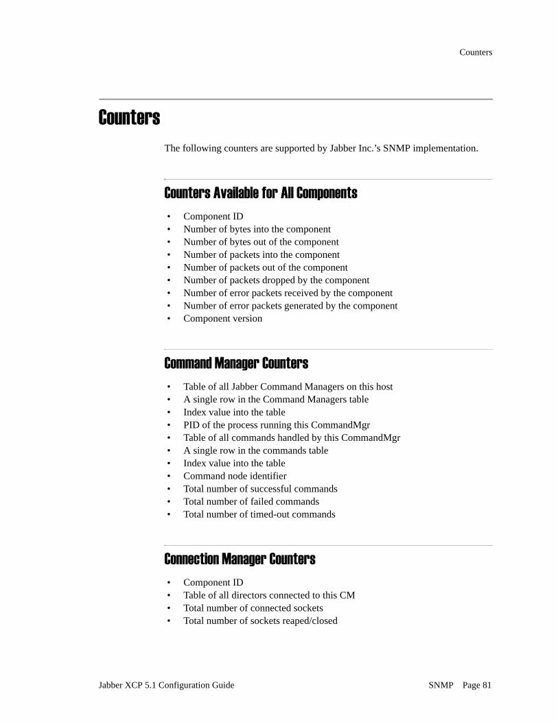
Counters
CountersThe following counters are supported by Jabber Inc.’s SNMP implementation.
Counters Available for All Components• Component ID• Number of bytes into the component• Number of bytes out of the component• Number of packets into the component• Number of packets out of the component• Number of packets dropped by the component• Number of error packets received by the component• Number of error packets generated by the component• Component version
Command Manager Counters• Table of all Jabber Command Managers on this host• A single row in the Command Managers table• Index value into the table• PID of the process running this CommandMgr• Table of all commands handled by this CommandMgr• A single row in the commands table• Index value into the table• Command node identifier• Total number of successful commands• Total number of failed commands• Total number of timed-out commands
Connection Manager Counters• Component ID• Table of all directors connected to this CM• Total number of connected sockets• Total number of sockets reaped/closed
Jabber XCP 5.1 Configuration Guide SNMP Page 81

Counters
File Transfer Proxy Counters• File Transfer Proxy transaction vectors• Number of files transferred• Number of files failed/rejected• Number of bytes transferred
JSM Counters• Component ID• Number of message stanzas received by this component• Number of message stanzas sent by this component• Number of presence stanzas received by this component• Number of presence stanzas sent by this component• Number of IQ stanzas received by this component• Number of IQ stanzas sent by this component• Current number of IM sessions being managed by this component• Current number of users online being managed by this component• Number of messages sent to offline storage by this component• Total number of successful sessions created by this component• Total number of failed attempts to create a session
Router Counters• Router ID• Number of connected components• Number of normal packets• Number of xdb packets• Number of log packets• Number of route packets• Id and port for connected component• Component ID• Remote host that runs this component• Port that is used by this component• Type of component (Service, log, xdb, etc.)• List of hosts for which this service gets packets• List of xdb namespaces to which this service responds• List of log namespaces to which this service responds
Page 82 SNMP Jabber XCP 5.1 Configuration Guide

Counters
Server-to-Server Counters• Number of connected incoming domains• Number of connected outgoing domains• Table of all server-to-server connection statistics• Hostname of connected server• Date connection was established• Number of packets sent/received on this connection• Time of last packet sent/received• Type of S2S Director - in/out
Text Conferencing Counters• ID for this component• Total number of all types of rooms• Total number of adHoc rooms• Total number of persistent rooms• Total number of rooms created• Total number of deleted rooms
Waitlist Counters• Waitlist transaction information• Table of waitlist transactions• A single row of transaction columns• Index value into the table• Number of successful transactions• Number of failed transactions• Number of currently pending transactions• Number of inbound viral marketing requests• Number of outbound viral marketing requests
Web Services Counters• ID for this component• Total number requests
Jabber XCP 5.1 Configuration Guide SNMP Page 83

Enabling SNMP
Enabling SNMPAs stated previously, you can use the XCP Controller to enable or disable the use of SNMP individually for each component and router plugin, including the core router. The following figure shows the area in the component and plugin configuration screens in which you enable SNMP.
To enable SNMP for a component or plugin:
1. In the configuration screen, scroll down to SNMP Configuration and click the checkbox next to it to enable the options. The Enable SNMP option is enabled by default.
2. Select Yes for Count Errors only if you want to enable SNMP error counting. This option takes a great deal of server resource; use it with caution.
3. Click Submit to save your configuration.
Page 84 SNMP Jabber XCP 5.1 Configuration Guide

Chapter 7. Single Domain Name Support
This chapter provides instructions for configuring the Single Domain Name Support (SDNS) component, one of the XCP server’s most advanced features.
The following sections are provided in this chapter:
• Overview• Configuring SDNS in Geographically Dispersed Installations• Configuring SDNS in Local Installations• Configuring SDNS for LDAP
OverviewSingle Domain Name Support (SDNS) provides a method of distributing the load for a single domain over multiple, equivalent components (for example, multiple JSM components). The SDNS component accomplishes this by allowing you to deploy a single domain name across a network of XCP routers and components on different pieces of hardware, even at different locations or with different subdomain names. SDNS allows two components with equivalent capabilities to act side by side, thereby reducing performance bottlenecks and increasing the number of concurrent users that are supported on each system.
Delivering a single domain name (also known as a single namespace) helps globally-based customers who want to disperse IT resources geographically or to obscure their network architecture from users. SDNS is also useful for customers with demanding scalability requirements.
Jabber XCP 5.1 Configuration Guide Single Domain Name Support Page 85

Overview
For example, using SDNS with two JSMs, the global domain, example.com, may be broken down into multiple subdomains using the JSMs’ hostnames (for example, denver.example.com and london.example.com). The SDNS component uses the JSMs’ id.realms (for example, jsm-1.denver and jsm-1.london) to map the correct subdomain within the global domain. The mapping between global domain and subdomain can be maintained in LDAP (using the SDNS Command) or in an RDBMS, and replicated across all sites. It may also be determined using a hashing algorithm. The SDNS component manages all packets bound for the global domain and rewrites the addresses on each stanza so that the router can redirect it to the appropriate subdomain. All rewriting is transparent to the user.
If you are using an LDAP database, you must configure the SDNS command in the Jabber Directory Suite rather than configuring an SDNS component. To configure the SDNS command, follow the instructions in “Configuring SDNS for LDAP” on page 102.
Which Components to Use with SDNSThe Jabber XCP components that make the most effective use of SDNS are JSM, Text Conferencing, and Information Broker. When you use SDNS to “front” for one or more of these components, you can configure an SDNS component on each router for each component. If you are configuring SDNS for geographically dispersed locations, you must also configure a Router-to-Router Connection component on the router that is establishing the outgoing connection.
SDNS is limited with regards to disco searches. When multiple, equivalent components are configured for SDNS, only one of the components will be searched when a disco request is received. For example, when multiple Text Conferencing components are configured for SDNS and a user searches for existing conference rooms, only one of the TC components will be searched. Likewise, for Information Broker, when a user searches for existing categories, only one of the Information Broker components will be searched.
Page 86 Single Domain Name Support Jabber XCP 5.1 Configuration Guide

Overview
Choosing a Mapping AlgorithmWhen you configure the SDNS component, you can choose between the database mapping algorithm and the modulo mapping algorithm (or you can write your own) to store the mapping between subdomains and the global domain in a supported database.
Modulo mapping algorithm
The Modulo Mapping Algorithm algorithmically determines the mapping between the global domain and subdomains, and is particularly effective if your scalability needs are high. This algorithm is faster than the database mapping algorithm; however, it provides less control over where stanzas are rerouted. The modulo mapping algorithm uses the mathematical function “modulo” to map to the correct subdomain within the global domain by hashing the user/host Jabber ID and using the integral hash value modulo the number of components.
Figure 15 shows the Modulo Mapping Algorithm section in the SDNS Configuration screen.
Figure 15. Modulo Mapping Algorithm configuration
The database mapping
algorithm
The database mapping algorithm is recommended for geographically distributed setups, and is used most effectively for JSM when users must be mapped to different locations, such as Denver and London. This algorithm is not as fast as the modulo mapping algorithm, but it provides finer control over where stanzas are rerouted.
Figure 16 shows the Database Mapping Algorithm section in the SDNS Configuration screen. SDNS will use the global database set up in the Core Router configuration if you do not configure the Database Setup option shown in the figure. If you prefer to use a database other than the one that is configured for the core router, you can configure another one here.
Jabber XCP 5.1 Configuration Guide Single Domain Name Support Page 87

Overview
Figure 16. Database Mapping Algorithm configuration
If you select the database mapping algorithm, you must insert mapping information (JID and MAPPED_HOST) into the SDNS_MAP table in your database.
If you have multiple SDNS components that use the database mapping algorithm, you must have a separate SDNS_MAP table for each component. The simplest way to give each SDNS component its own set of tables is to configure each component to connect to the database with a different database username.
Page 88 Single Domain Name Support Jabber XCP 5.1 Configuration Guide

Configuring SDNS in Geographically Dispersed Installations
DaData
InfoDat
Data
B
sB
Figure 17. Multiple SDNS components and SDNS_MAP tables
Configuring SDNS in Geographically Dispersed InstallationsThis section provides two example SDNS configurations for the hypothetical company, example.com, which has one XCP installation in Denver and another in London. During installation, the realm for the Denver router was specified as “denver”; likewise, the London router was given the realm, “london”. The configuration of SDNS for a remote deployment of this type requires you to:
• Configure an SDNS component on each router for every component being fronted by SDNS. For example, if you are using SDNS for JSM and for Information Broker, you must have two SDNS components on each router: one for JSM and one for Information Broker. (This scenario is described in “Example – Configuring SDNS for JSM and Information Broker” on page 94.)
• Configure a Router-to-Router Connection component on the router that is establishing the outbound connection.
Text Conferencing SDNSDatasource Name=PostgresDatabase User Name=TCDB
Text Conferencing SDNSDatasource Name=Oracle
Database User Name=TCDB
JSM SDNStasource Name=Oraclebase User Name=JSMDB
Each database/tablespace has its own
SDNS_MAP table.
rmation Broker SDNSasource Name=Oraclebase User Name=IBDB
jabberdrealm=denver
JSM SDNSDatasource Name=Postgres
Database User Name=JSMD
Information Broker SDNSDatasource Name=PostgreDatabase User Name=IBD
denver.example.com london.example.com
TC table
JSM table
IB table
TC table
JSM table
IB table
Database Database
jabberdrealm=london
Router-to-Router
connection
Jabber XCP 5.1 Configuration Guide Single Domain Name Support Page 89

Configuring SDNS in Geographically Dispersed Installations
Example – Configuring SDNS for Text ConferencingFigure 18 illustrates how SDNS is being used for Text Conferencing in the company, example.com. The SDNS components and the Router-to-Router Connection are facilitating communication between the Text Conferencing components on the two routers, thus allowing users in both Denver and London to participate in conference rooms created on either router without having to know on which physical server a conference room is located. As you can see, for this configuration, each router must have a TC component and an SDNS component. The Router-to-Router Connection component is configured on the Denver router, which has established the outbound connection.
In this example, we’ll use the Modulo Mapping Algorithm when we configure the SDNS components. An example of using the Database Algorithm is provided in “Configuring SDNS for JSM” on page 96.
Figure 18. Example SDNS configuration for Text Conferencing
SDNStc-1.denvertc-1.london
Text Conferencingtc-1.denver
jabberdrealm=denver
jabberdrealm=london
SDNStc-1.denvertc-1.london
Router-to-RouterConnection
conference.example.com conference.example.com
Text Conferencingtc-1.london
[email protected]/denver
Denver London
Connection Mgr
jsmcp.london
Connection Mgr
jsmcp.denver
Denver establishedoutgoing connection
[email protected]/london
Page 90 Single Domain Name Support Jabber XCP 5.1 Configuration Guide

Configuring SDNS in Geographically Dispersed Installations
Configuring the Text
Conferencing component
In order to work correctly, the Text Conferencing configuration must not contain any hostnames. (This is true for the TC components on both routers.) The hostname that would ordinarily be entered in the TC configuration is, instead, entered in the SDNS Configuration screen.
To configure the TC component
1. In the Components area on the Controller’s main screen, click the Edit link beside the tc component.
2. In the Text Conferencing Configuration screen, scroll down to the Hostnames for this Component area, and remove the hostname from the text field as shown in the following figure.
3. Click Submit to save your configuration.
Jabber XCP 5.1 Configuration Guide Single Domain Name Support Page 91

Configuring SDNS in Geographically Dispersed Installations
Configuring the SDNS
component
The SDNS components on both routers must be configured using the Text Conferencing hostnames and the id.realms of the Text Conferencing components in both locations.
You must use the Controller’s Advanced configuration view to configure the SDNS component.
To configure the SDNS component
1. In the Components area on the Controller’s main screen, select Single Domain Name Support in the drop-down list and click Go.
2. In the Single Domain Name Support Configuration screen, scroll down to the Hostnames for this Component area. By default, the text field contains the hostname of the XCP server.
3. Enter the TC hostname in the text field; for example, conference.example.com.
4. Scroll down to the Single Domain Name Support Configuration area. You can choose either the Modulo Mapping Algorithm or the Database Mapping Algorithm. In this example, we’ll use the Modulo Mapping Algorithm.
5. Click the Modulo Mapping Algorithm radio button to enable the feature.
6. In the Components text field, enter the id.realms of the TC components on each router; for example, tc-1.denver and tc-1.london.
Page 92 Single Domain Name Support Jabber XCP 5.1 Configuration Guide

Configuring SDNS in Geographically Dispersed Installations
7. Click Submit to save your configuration.
Configuring a Router-to-
Router Connection
Finally, to establish communication between the Denver and London routers, you must configure a Router-to-Router Connection component on the router that is making the outbound connection. In this example, we’ll configure the component on the Denver router.
To configure the Router-to-Router Connection on the Denver router
1. In the Components area on the Controller’s main screen, select Router-to-Router Connection in the drop-down list, and click Go.
2. In the Router-to-Router Connection Configuration screen, do the following:
- Change to the Controller’s Advanced configuration view (you should already be using that view from configuring SDNS).
- For Component IP, enter the London router’s IP address.
- For Port, enter the port specified for the London router’s Master Accept Port.
Jabber XCP 5.1 Configuration Guide Single Domain Name Support Page 93

Configuring SDNS in Geographically Dispersed Installations
- For Password, enter the password specified for the London router’s Master Accept Port.
3. Click Submit to save your configuration.
Example – Configuring SDNS for JSM and Information BrokerThis example provide a slightly more complex scenario in which SDNS is being configured for both JSM and Information Broker in the company, example.com. The following figure illustrates the use of SDNS to distribute the load across two JSMs. It also illustrates the use of SDNS to facilitate communication between the Information Broker components on the two routers, allowing users in both Denver and London to create, publish to, and subscribe to nodes within categories on either router. As you can see, for this configuration, each router must have a JSM, an Information Broker component, and two SDNS components. A Router-to-Router Connection component must be configured on the router that is establishing the outbound connection: in this example, Denver.
Page 94 Single Domain Name Support Jabber XCP 5.1 Configuration Guide

Configuring SDNS in Geographically Dispersed Installations
Figure 19. SDNS Configuration for JSM and Information Broker
Configuring JSM In order to work correctly with SDNS, the Jabber Session Manager configurations on both routers must not contain any hostnames. The hostname that would ordinarily be entered in the JSM configuration is, instead, entered in the SDNS configuration.
To configure the JSM plugins
1. In the Router area on the Controller’s main screen, click the Edit link beside Jabber Session Manager.
2. In the Jabber Session Manager Configuration screen, scroll down to the Hostnames for this Component area and remove the hostname from the text field as shown in the following figure.
SDNSinfo-broker-1.denverinfo-broker-1.london
Information Brokerinfo-broker-1.denver
jabberdrealm=denver
jabberdrealm=london
SDNSinfo-broker-1.denverinfo-broker-1.london
SDNSjsm-1.denverjsm-1.london
JSMjsm-1.denver
JSMjsm-1.london
SDNSjsm-1.denverjsm-1.london
Open PortID=London
Connection Mgr
info-broker.example.com info-broker.example.com
jsmcp.denver
Connection Mgr
jsmcp.london
Information Brokerinfo-broker-1.london
example.com example.com
[email protected]/denver
[email protected]/london
Denver London
Denver establishedoutbound connection
Jabber XCP 5.1 Configuration Guide Single Domain Name Support Page 95

Configuring SDNS in Geographically Dispersed Installations
3. Scroll down to the JSM Features area, and select Yes beside Apply Single Domain Name Support semantics to local user lookups.
4. Click Submit to save your configuration.
5. Repeat this procedure for the JSM plugin on the other router.
Configuring SDNS for JSM
You must configure an SDNS component on each router for the corresponding JSM plugins. In this example, the SDNS components are configured using the database mapping algorithm. This algorithm is used most effectively for JSM when users are being mapped to different locations.
To configure SDNS components for JSM
1. In the Components area of the Controller’s main screen, select Single Domain Name Support from the drop-down list, and click Go.In the Single Domain Name Support Configuration screen, scroll down to the Hostnames for this Component area. In the text box, enter the JSM hostname; for example; example.com.
2. Scroll down to the Single Domain Name Support Configuration area, and click the radio button above Database Mapping Algorithm to enable the option. Do the following:
- Under Algorithm Input Generator, make sure that standard_algo_input is selected in the Load drop-down list.
Page 96 Single Domain Name Support Jabber XCP 5.1 Configuration Guide

Configuring SDNS in Geographically Dispersed Installations
- If you want to use a database other than the database configured in the Core Router configuration, select the Database Setup option. Configure the settings using the online help as needed.
You must use the sdns_util program (located in $JABBER_HOME/support) to insert users’ Jabber IDs and Mapped_Hosts into your database.
3. In the Default Mapping for lookup failure text field, enter the id.realm of the component to which you want to direct host-only Jabber IDs. The component that you specify here is the “catch-all” component to which users, conference rooms, or nodes are directed when they are not listed in the SDNS_MAP table in your database. For example, if you specify tc-2.denver here, all of the conference rooms that are not listed in your SDNS_MAP table will be directed to the Text Conferencing component, tc-2.denver.
Since all unresolved database lookups will be directed to the “catch-all” host, you might consider using a more powerful machine for the host.
4. Click Submit to save your configuration.
5. Repeat this procedure for the SDNS component on the other router.
Jabber XCP 5.1 Configuration Guide Single Domain Name Support Page 97

Configuring SDNS in Geographically Dispersed Installations
Configuring Information
Broker
The Information Broker configurations on both routers must contain no hostnames. The hostname that would ordinarily be entered in the Information Broker configuration is, instead, entered in the SDNS configuration.
To configure the Information Broker components
1. In the Component area on the Controller’s main screen, click the Edit link beside Information Broker.
2. In the Information Broker Configuration screen, scroll down to the Hostnames for this Component area, and remove the hostname from the text field.
3. Click Submit to save your configuration.
4. Repeat this procedure for the Information Broker component on the other router.
Configuring SDNS for
Information Broker
You must configure an SDNS component on each router for the corresponding Information Broker components. In this example, the Modulo Mapping Algorithm in the SDNS configuration is used.
To configure SDNS Components for Information Broker
1. In the Components area of the Controller’s main screen, select Single Domain Name Support from the drop-down list, and click Go.
Page 98 Single Domain Name Support Jabber XCP 5.1 Configuration Guide

Configuring SDNS in Geographically Dispersed Installations
2. In the Single Domain Name Support Configuration screen, scroll down to the Hostnames for this Component area. In the text box, enter the Information Broker hostname; for example; info-broker.example.com.
3. Scroll down to the Single Domain Name Support Configuration area, and click the radio button above Modulo Mapping Algorithm to enable the option. Do the following:
- Under Algorithm Input Generator, select infobroker_algo_input in the Load drop-down list.
- In the Components text box, enter the id.realms of the Information Broker components that are configured on each router; for example:
info-broker-1.denver info-broker-1.london
These id.realms must be entered in the same order in each cooperating SDNS component’s configuration.
4. Click Submit to save your configuration.
5. Repeat this procedure for the SDNS component on the other router.
Jabber XCP 5.1 Configuration Guide Single Domain Name Support Page 99

Configuring SDNS in Geographically Dispersed Installations
Configuring a Router-to-
Router Connection
Finally, you must configure a Router-to-Router Connection component on the router that is making the outbound connection. In this example, we’ll configure the component on the Denver router.
To configure the Router-to-Router Connection on the Denver router
1. In the Components are on the Controller’s main screen, select Router-to-Router Connection in the drop-down list, and click Go.
2. In the Router-to-Router Connection Configuration screen, do the following:
- Change to the Controller’s Advanced configuration view (you should already be using that view from configuring SDNS).
- For Component IP, enter the London router’s IP address.
- For Port, enter the port specified for the London router’s Master Accept Port.
- For Password, enter the password specified for the London router’s Master Accept Port.
3. Click Submit to save your configuration.
Page 100 Single Domain Name Support Jabber XCP 5.1 Configuration Guide

Configuring SDNS in Local Installations
Configuring SDNS in Local InstallationsA “local installation” is one in which multiple routers are installed within the same physical subnet and share the same cluster. Jabber XCP’s new dynamic routing feature enables all components within the installation, regardless of which router they are installed on, to discover each other automatically.
To use SDNS in this scenario, you must still configure an SDNS component on each router for each component that is using SDNS. The only difference in this configuration and the geographically distributed configuration is that a Router-to-Router Connection component is not required for the routers to communicate.
For example, let’s say that a local configuration has two routers (as shown in Figure 20), and that both routers have a TC component. You want users connected to either router to be able to use TC rooms that exist across the entire installation. You must configure an SDNS component for TC on each router. Through dynamic routing, each router becomes aware of the new SDNS component on the other, and updates its routing table accordingly. TC users connected to either router are now able to see and use TC rooms configured on both routers without being aware of which router the rooms are on.
Figure 20. SDNS in a Local Installation
SDNS-1.R1 SDNS-1.R2
R1 R2
TC-1.R2TC-1.R1
This connectionhappens automatically
Same physicalsubnet
Same cluster
Jabber XCP 5.1 Configuration Guide Single Domain Name Support Page 101

Configuring SDNS for LDAP
Configuring SDNS for LDAPIf you are using an LDAP database, you must configure the SDNS command within your Jabber Directory Suite (JDS) component rather than configuring an SDNS component as described in the previous sections in this chapter. The SDNS command allows you to use LDAP attributes to map users and hosts to subdomain names, and to map global domains to subdomains when no user is provided. In almost all cases, the SDNS command sends users to different JSMs. When you configure the SDNS command, the JDS, in effect, becomes your SDNS component.
This method is especially effective for configuring SDNS in geographically distributed setups, and is typically applied against JSM.
To configure SDNS for LDAP
1. In the Components area on the Controller’s main screen, select Jabber Directory Suite in the drop-down list, and click Go.
2. Configure the JDS component using the Controller’s online help.
3. Under Databases, click Go to add an LDAP database. This is where you will configure the SDNS command.
4. Configure your LDAP database using the online help.
Page 102 Single Domain Name Support Jabber XCP 5.1 Configuration Guide

Configuring SDNS for LDAP
5. In the JDS Command Definitions area on the Database Configuration screen, click the checkbox beside Single Domain Name Support (SDNS) to enable the command.
6. Enter the required information as described in the following table:
7. When you have finished configuring the LDAP database, click Submit to save your configuration. You are returned to the Jabber Directory Suite Configuration screen.
8. When you have finished configuring the Jabber Directory Suite, click Submit. You are returned to the Controller’s main screen.
9. Since the SDNS feature is applied to JSM when you configure it through JDS, you must modify the JSM plugin in the same way it is modified when the SDNS component is used (see “Configuring JSM” on page 95).
In the Router area on the Controller’s main screen, click the Edit link beside Jabber Session Manager.
Text field Description
Custom Library Leave this field blank unless you want to use a custom SDNS command.
The host name to map Enter the server name of the global domain being mapped; for example; example.com.
The LDAP entry attribute containing the host map value
Enter the LDAP attribute that contains the domain used to rewrite users’ Jabber IDs; for example, jabberHost. For example, if the Jabber ID [email protected] must be rewritten as [email protected] the jabberHost attribute should contain denver.example.com.
The component ID to use when rewriting host-only addresses
Enter the id.realm of the authoritative responder to requests that contain only a server name without a userid; for example, disco requests.
Since this command is used mainly to send users to different JSMs, an example id.realm is jsm-1.jabber.
Jabber XCP 5.1 Configuration Guide Single Domain Name Support Page 103

Configuring SDNS for LDAP
10. In the Jabber Session Manager Configuration screen, scroll down to the Hostnames for this Component area, and remove any hostnames from the text field.
11. Scroll down to the JSM Features area, and select Yes beside Apply Single Domain Name Support semantics to local user lookups.
12. Click Submit to save your configuration. You are returned to the Controller’s main screen.
13. Restart the XCP server.
Page 104 Single Domain Name Support Jabber XCP 5.1 Configuration Guide

Chapter 8. WebServices
This chapter describes how to configure the Web Services package to allow custom-built applications and components to access Jabber XCP services, including messaging, roster/presence, and Information Broker. (Installation instructions are provided in the “Special Features” chapter in the Jabber XCP Installation Guide.
The following sections are provided:
• Configuring Web Services• Service-Specific Configurations• Invoking Services from a SOAP-over-HTTP Client• Web Services Definition Language Files
Configuring Web ServicesYou must configure Web Services through the Jabber XCP Controller, which is the Web-based interface used to configure the Jabber XCP server’s components and plugins. Instructions for starting the Jabber XCP Controller are provided in the “Standard Operations” chapter in the Jabber XCP Installation Guide.
Online help is provided with the Jabber XCP Controller. Use the help to answer any questions you may have regarding text field and option definitions.
Jabber XCP 5.1 Configuration Guide WebServices Page 105

Configuring Web Services
Add a Web Services ComponentThe Web Services component specifies which Jabber XCP services are available to the Web Services application.
To add a Web Services component to your Jabber XCP configuration
1. Change to the Controller’s Intermediate or Advanced configuration view.
2. In the Components area on the Controller’s main screen, select Web Services from the drop-down list and click the Go button.
3. In the Web Services Configuration screen, configure the Web Services component using the Controller’s online help if necessary. (The first Web Services component that you add will have web-services-1 for its ID.)
4. In the Services section (shown below), click the Go button to add a Web service.
The Service Configuration screen displays.
Page 106 WebServices Jabber XCP 5.1 Configuration Guide

Configuring Web Services
5. In the Service Configuration screen, enter one of the following namespaces in the Namespace for this service field depending on the service you want to make available:
- http://jabber.com/webservices/Messaging- http://jabber.com/webservices/RosterPresence- http://jabber.com/webservices/InfoBroker
These namespaces are built into the WebServices API and are the only ones currently supported. Do not modify them.
6. Leave the Service library field blank unless you are using a custom library.
7. In the Service load function field, enter the server function that loads the service; depending on the namespace you entered in step 5, the function is one of following:
- ws_messaging- ws_rosterpresence- ws_infobroker
8. Submit the service configuration. You are returned to the Web Services Configuration screen.
9. From the Web Services Configuration screen, add more services as needed.
10. Click Submit to save your configuration.
Configure a Web Services Connection ManagerIn order to facilitate high performance for Web Services, we recommend that you configure a separate CM for each Web Services component that you add to the Jabber XCP configuration. (In other words, do not add a the Web Command Processor to an existing CM.)
The Web Services Connection Manager is configured with a Web Command Processor (WebCP), which has a SOAPHandler. The WebCP SOAPHandler is used when Web Services applications send SOAP-over-HTTP requests to the Jabber XCP server. It provides the ability to map a URL to a dynamically-loaded handler. The SOAPHandler is responsible for taking the SOAP-over-HTTP request, authenticating it, and translating it into SOAP over XMPP so that it can be routed to the Web Services Component. When a response comes in from the Web Services component, the WebCP SOAPHandler translates it back into SOAP over HTTP, and writes the result back to the requesting application.
Jabber XCP 5.1 Configuration Guide WebServices Page 107

Configuring Web Services
Figure 21. Web Services CM with WebCP and SOAPHandler
To add and configure a Web Services Connection Manager
1. In the Components area on the Controller’s main screen, select Connection Manager from the drop-down list and click the Go button. The Connection Manager Configuration screen displays.
2. Configure the CM’s settings using the Controller’s online help if needed.
You can change the default port number if necessary.
3. In the Add a New Command Processor section, select Web Command Processor in the drop-down list, and click the Go button.
Web ServicesOpen Port
Component
Connection Manager
HTTP DirectorFamily
WebCP
SOAP overHTTP
Web ServicesApplication
SOAPHandler
SOAP overXMPP
HTT
PD
irect
or HTTP Gaffer
HTTPTranscoder
WebCP
HTTP
Router Web ServicesComponent
Page 108 WebServices Jabber XCP 5.1 Configuration Guide

Configuring Web Services
You must be in the Controller’s Advanced configuration mode to configure a Web Services Command Processor.
The first Web Command Processor that you add will have an ID of cm-2_webcp-1 as shown here:
4. In the Director Configuration area, click the Go button to add an HTTP director. The configuration screen is shown in the following figure.
Jabber XCP 5.1 Configuration Guide WebServices Page 109

Configuring Web Services
5. Configure the director’s settings using the online help if needed.
The default port number of the director’s external channel is 7335 (this implements an HTTP server on port 7335 to serve incoming SOAP requests). You can change the port number if necessary.
6. Submit the director’s configuration. You are returned to the WebCP Configuration screen.
7. In the Handlers area on the WebCP Configuration screen, select Web Services Handler in the drop-down list, and click Go. The Web Services Handler enables the WebCP to communicate with the XCP router, jabberd.
The Web Services Handler Configuration screen is shown in the following figure.
8. In the Web Services Handler Configuration screen, enter the path, /soap. This path is referenced in the WSDL.
9. Submit your configuration both in this screen and in the WebCP Configuration screen.
Page 110 WebServices Jabber XCP 5.1 Configuration Guide

Configuring Web Services
Add Web Services as a Jabber AdministratorYou must add the ID and realm of the Web Services component as a Jabber administrator in the Jabber Session Manager (JSM) plugin.
The default realm is “jabber.” To see the realm for the current Jabber XCP installation, click the Edit link beside the Core Router in the Plugins area on the Jabber XCP Controller’s main screen. The realm is the second entry under “Global Settings.”
To edit the JSM configuration
1. In the Router area on the Controller’s main screen, click the Edit link beside the JSM plugin to edit the configuration.
2. In the Jabber Session Manager Configuration screen, add the ID and realm of the Web Services component (for example, web-services-1.jabber) as a Jabber administrator as shown in the following figure.
3. Click Submit to save your configuration.
Configure a Web Services AdministratorThe Web Services component must be able to authorize requests coming in from the Web Services Handler. For this to happen, the Web Services Handler must be added as an administrator in the Web Services configuration.
To configure the Web Services administrator
1. In the Components area on the Controller’s main screen, click the Edit link beside the Web Services component.
2. In the Web Services Configuration screen, add the ID and realm of the Web Services Handler (for example, cm-2_webcp-1_websvch-1.denver) as an administrator as shown in the following figure.
Jabber XCP 5.1 Configuration Guide WebServices Page 111

Service-Specific Configurations
3. Click Submit to save your configuration.
Service-Specific ConfigurationsThis section describes extra steps that you must take to configure broadcast messages, offline messages, and the Information Broker service.
Broadcast MessagesThe broadcast message function is part of the Messaging service. To enable this function, you must modify the JSM Command Processor’s configuration.
To enable broadcast messages
1. In the Components area on the Jabber XCP Controller’s main screen, click the Edit link beside the CM component that is configured with a JSM Command Processor. (The CM component that is installed by default with the Jabber XCP server contains a JSM Command Processor.)
If multiple CM components have JSM Command Processors, you must follows these steps for each one.
Page 112 WebServices Jabber XCP 5.1 Configuration Guide

Service-Specific Configurations
2. In the Add a new command processor section click the Details link beside the name of the JSM command processor.
The JSM Command Processor Configuration screen displays as shown below:
3. In the lower portion of the JSM Command Processor Configuration screen, select Yes beside Enable Broadcast to all online users connected to this CM.
4. Click Submit to save your configuration.
Jabber XCP 5.1 Configuration Guide WebServices Page 113

Service-Specific Configurations
Offline MessagingTo enable offline messaging to work correctly with Web Services, the mod_offline_pop module in the JSM configuration must be enabled. The module is enabled by default, and is required for JEP-0013 functionality. Do not change this setting without first consulting Jabber, Inc. support.
To verify that the mod_offline_pop module is enabled
1. Change to the Controller’s Advanced configuration view.
2. In the Router area on the Controller’s main screen, click the Edit link beside the JSM plugin.
3. In the JSM Configuration screen, under Optional modules, ensure that the checkbox beside mod_offline_pop is enabled as shown below:
4. If you made any changes, click Submit to save the configuration.
Page 114 WebServices Jabber XCP 5.1 Configuration Guide

Invoking Services from a SOAP-over-HTTP Client
Information BrokerThe Information Broker service can create a node and publish information to a node on behalf of a user. To use this service, you must have an Information Broker component in your Jabber XCP server configuration.
To configure the Information Broker for Web Services
1. In the Components area on the Controller’s main screen, click the Edit link beside the Information Broker component.
2. In the Information Broker Configuration screen, scroll down to the Information Broker Administrators area.
3. In the Admin(s) field, enter the ID and realm of the Web Services component (for example, web-services-1.denver).
4. Click Submit to save your configuration.
Invoking Services from a SOAP-over-HTTP ClientTo invoke Web services from a SOAP-over-HTTP client, the user sends a SOAP-over-HTTP message to the WebCP SOAPHandler; for example, http://user:[email protected]:7336/soap. User and password must match the username and password that were specified for Web Services during the package’s installation. The username and password are stored in $JABBER_HOME/etc/.websvc_passwd.
You can modify the password if needed by using the admin password command to access the websvc_passwd file.
The WebCP SOAPHandler performs HTTP basic authentication on the message and, if passed, forwards the message to the Web Services component.
Jabber XCP 5.1 Configuration Guide WebServices Page 115

Web Services Definition Language Files
Web Services Definition Language FilesThree Web Service Definition Language (WSDL) files are provided with the Web Services package installation. The WSDL files provide all of the information that a client development environment needs in order to generate the framework to invoke the services. The files are located at:
• $JABBER_HOME/htdocs/wsdl/web-services/Messaging.wsdl• $JABBER_HOME/htdocs/wsdl/web-services/RosterPresence.wsdl• $JABBER_HOME/htdocs/wsdl/web-services/InfoBroker.wsdl
Assuming that the controller application is running and listening on port 7300, you can access these files via HTTP by pointing your browser to, for example: https://server.com:7300/wsdl/web-services/Messaging.wsdl
If you have trouble accessing the files through your browser, make sure that you have permissions to access them.
Page 116 WebServices Jabber XCP 5.1 Configuration Guide

Chapter 9. HTTP Polling Connections
This chapter provides instructions for configuring an HTTP Polling Connection Manager for your XCP server. HTTP polling connections enable you to use Jabber Inc.’s WebClient and other HTTP clients. This type of connection allows users to access your XCP server without requiring any changes to network or firewall settings.
The process for configuring an HTTP polling connection involves adding a new Connection Manager (CM) to your XCP server. This CM must be configured with a JSM Command Processor and an HTTP Polling director. In this chapter, we set the director’s port to 8080. If you want the director to listen on port 80 or 443, you must start the CM as root.
Figure 22 illustrates the CM that WebClient uses to connect to the Jabber XCP server using Polling XMPP over HTTP. The figure also shows the CMs used by the XCP Controller and by the Jabber Messenger client.
Jabber XCP 5.1 Configuration Guide HTTP Polling Connections Page 117
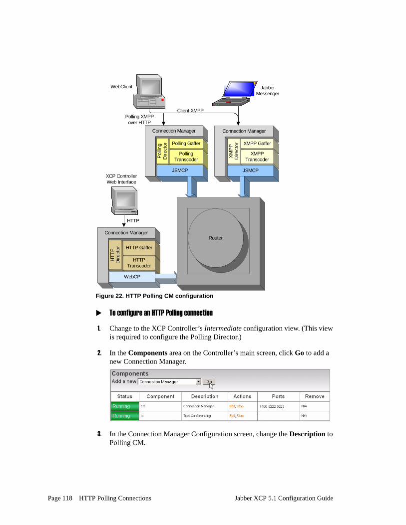
Figure 22. HTTP Polling CM configuration
To configure an HTTP Polling connection
1. Change to the XCP Controller’s Intermediate configuration view. (This view is required to configure the Polling Director.)
2. In the Components area on the Controller’s main screen, click Go to add a new Connection Manager.
3. In the Connection Manager Configuration screen, change the Description to Polling CM.
Connection Manager
Pol
ling
Dire
ctor Polling Gaffer
PollingTranscoder
JSMCP
Connection Manager
HTT
PD
irect
or HTTP Gaffer
HTTPTranscoder
WebCP
HTTP
Connection Manager
XMPP
Dire
ctor XMPP Gaffer
XMPPTranscoder
JSMCP
Router
WebClient JabberMessenger
Polling XMPPover HTTP
Client XMPP
XCP ControllerWeb Interface
Page 118 HTTP Polling Connections Jabber XCP 5.1 Configuration Guide

4. Under Add a New Command Processor, click Go to add a JSM Command Processor.
5. In the JSM Command Processor Configuration screen, select Polling Director in the drop-down list, and click Go.
6. In the Polling Director Configuration screen, do the following:
- Change the Port to 8080. (If you want to use port 80 or 443, you must start the CM as root.)
- Click the checkbox beside SSL Settings if you want to enable SSL.
Caution! The XCP server does not support private keys for SSL certificates that have pass phrases. If you have a pass phrase or encrypt your private key, your private key/public certificate pair will not load into XCP.
- Click Submit to save your configuration. You are returned to the JSM Command Processor Configuration screen.
Jabber XCP 5.1 Configuration Guide HTTP Polling Connections Page 119

7. Click Submit in the JSM Command Processor Configuration screen. You are returned to the Connection Manager Configuration screen.
8. In the Connection Manager Configuration screen, perform any additional configuration if needed, then click Submit to save your configuration.
No additional configuration is required. You can submit the CM using its remaining default settings.
Page 120 HTTP Polling Connections Jabber XCP 5.1 Configuration Guide

Chapter 10. Setting Up Active Directory Authentication
This chapter provides instructions for configuring JDS for authentication and user search using Active Directory. The process does not involve extending your ADS schema.
The following tasks are involved:
• Configure a Jabber Directory Suite Component• Configure JSM to use JDS
Configure a Jabber Directory Suite ComponentThis section describes how to add and configure a Jabber Directory Suite component, which contains a directory server and an LDAP database.
To configure a JDS component
1. Change to the Controller’s Intermediate configuration view.
2. In the Components area on the Jabber XCP Controller’s main screen, select Jabber Directory Suite in the drop-down list, and click Go.
Jabber XCP 5.1 Installation Guide Setting Up Active Directory Authentication Page 121

Configure a Jabber Directory Suite Component
3. In the Jabber Directory Suite Configuration screen, scroll down to the XDB Filters section, and select all of the namespace filters with the exception of jcp:serverprefs.
4. Under Hostnames for this Component, enter ldapsearch.yourJabberServerName.com in the Host Filters text box. This configures JDS to accept user search requests.
5. Scroll down to the LDAP area, and click Go beside Add a Directory Server.
The Directory Server Configuration screen displays.
Page 122 Setting Up Active Directory Authentication Jabber XCP 5.1 Installation Guide

Configure a Jabber Directory Suite Component
Configure a Directory ServerIn the Directory Server Configuration screen, you configure the connection to your Active Directory server.
To configure the directory server
1. Using the online help for field descriptions, enter the required information.
The Directory server hostname is probably your Global Catalog (GC) server, but could differ based on your setup of AD. The Directory Server user is the DN of an administrator account or other account that has read access to the authentication information in AD. The GC port is 3268.
2. Click the Submit button to submit your configuration. You are returned to the Jabber Directory Suite Configuration screen.
3. In the JDS Configuration section, click the Go button beside Databases. The Database Configuration screen displays.
Jabber XCP 5.1 Installation Guide Setting Up Active Directory Authentication Page 123

Configure a Jabber Directory Suite Component
Configure an LDAP DatabaseThis section describes how to configure the LDAP database.
To configure the LDAP Database
1. In the Database Configuration screen in the Host Filters text field, enter an asterisk (*) as shown below.
2. Beside Add a new server, click the Go button. The Server Configuration screen displays.
3. In the Server Configuration screen, enter the ID of the directory server that you created (see page 123). If you used the default value when you configured the directory server, its ID is “server-1” as shown below.
4. Click the Submit button to save your server configuration. You are returned to the Database Configuration screen.
5. On the Database Configuration screen under Jabber User Configuration, enter the values described in the following table to specify your ADS setup.
Page 124 Setting Up Active Directory Authentication Jabber XCP 5.1 Installation Guide

Configure a Jabber Directory Suite Component
The values you must enter are described as follows:
6. Next you must define how JDS will build your JIDs. Under Select exactly one of the following options, select Static User JID.
The values you must enter are described as follows:
7. Scroll down to the JDS Command Definitions section, click the checkbox next to Authentication, and select Plain-Text Authentication. You do not need to enter a custom library.
Option Description
LDAP object class for users This value is probably going to be ‘User.’
Base context for this LDAP class
The base context is specific to your AD configuration. For example, an AD server for the domain, example.com, with all of its users in the Users group would require the following base context:cn=users,dc=example,dc=com
LDAP attribute to use for the Jabber display name
The common attribute used is displayName.
Option Description
User Attribute Enter the following:sAMAccountName
Host Enter the hostname of your Jabber server; for example: jabber.example.com
Jabber XCP 5.1 Installation Guide Setting Up Active Directory Authentication Page 125

Configure a Jabber Directory Suite Component
8. Click the checkbox next to Register Check so that JDS can validate Jabber users. Again, you do not need to enter a custom library.
9. Click the checkbox next to ldapSearch command so that Jabber users can search for other user accounts. (This is not the same thing as vCard information.)
10. Click Go, and add the LDAP attributes in the Searchable LDAP Attribute Configuration screen. Click Submit when you have finished.
The LDAP attributes in Active Directory for email, first name, and last name are mail, givenName, and sn respectively. Do not enter spaces in the descriptions.
11. You have now configured all of the JDS subcomponents. Click Submit on the Database Configuration screen, and on the Jabber Directory Suite Configuration screen to save your configuration.
Page 126 Setting Up Active Directory Authentication Jabber XCP 5.1 Installation Guide

Configure JSM to use JDS
Configure JSM to use JDSNow that JDS is up and running, you must configure the Jabber Session Manager to use JDS.
To configure JSM to use JDS
1. Change to the Controller’s Basic configuration view.
2. In the Router area on the Controller’s main screen, click the Edit link beside Jabber Session Manager to display the Jabber Session Manager Configuration screen.
3. Under Optional modules, click the checkbox beside mod_jds. Clear the checkboxes next to mod_auth_plain, mod_auth_digest, and mod_register. This enables JDS for authentication and turns off the default authentication.
4. Click the checkbox next to JDS Configuration to enable the option. Make sure that both the Digest Authentication and Community Groups options are set to No.
Jabber XCP 5.1 Installation Guide Setting Up Active Directory Authentication Page 127

Configure JSM to use JDS
5. Scroll down to the Registration Requirements option and clear the checkbox to disable it, since your users are already registered in Active Dirctory.
6. Click Submit to save the configuration.
7. From the Controller’s main screen, restart the server.
8. Test the new configuration by logging into the Jabber XCP server with the Jabber Messenger client, specifying a username and password for a valid AD account. If the login fails, check the JDS component configuration, syslog, and LDAP logs for more detail.
Page 128 Setting Up Active Directory Authentication Jabber XCP 5.1 Installation Guide

Index
AAdvanced File Transfer 23
configuring an open port 30configuring the handler 25overview of 12
architectureXCP 5.1 8
BBreeze Collaboration Command 74
configuring 75
Cclusters
overview of 14component
descriptions of 9logging 54
configurationguidelines 20views in the Controller 17
Connection Managercomponent description 9
ControllerComponent area on main screen 20configuration views 17how to use 16online help 20Router area on main screen 19System area on main screen 18
Core Routerdescription of 11
counters for SNMP 81custom LaunchBroker command
configuring 76custom logger 58
Ddatabase mapping algorithm 87debug log level 41dynamic routing
overview of 14
Eerror log level 41
Ffile logger
configuring 46File Transfer Proxy
component description 9filtered stream logger 57filtered syslog logger 55firewall considerations 21formatting logs 47
Hhardware considerations 22host filters
Jabberd Logger 45
Iinfo log level 41Information Broker
component description 9configuring for SDNS 94, 98
IQ packets 50
JJabber Directory Suite
component description 9Jabber Logging Library 54Jabber Session Manager
description of 11Jabber User Directory
component description 9
Jabber XCP 5.1 Configuration Guide - DRAFT Page 129
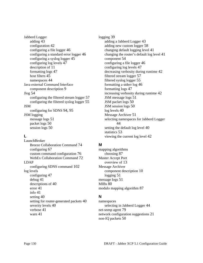
Jabberd Loggeradding 43configuration 42configuring a file logger 46configuring a standard error logger 46configuring a syslog logger 45configuring log levels 47description of 11formatting logs 47host filters 45namespaces 44
Java external Command Interfacecomponent description 9
Jlog 54configuring the filtered stream logger 57configuring the filtered syslog logger 55
JSMconfiguring for SDNS 94, 95
JSM loggingmessage logs 51packet logs 50session logs 50
LLaunchBroker
Breeze Collaboration Command 74configuring 67custom command configuration 76WebEx Collaboration Command 72
LDAPconfiguring SDNS command 102
log levelsconfiguring 47debug 41descriptions of 40error 41info 41setting 40setting for router-generated packets 40severity levels 40verbose 41warn 41
logging 39adding a Jabberd Logger 43adding new custom logger 58changing default logging level 41changing the router’s default log level 41component 54configuring a file logger 46configuring log levels 47decreasing verbosity during runtime 42filtered stream logger 57filtered syslog logger 55formatting a stderr log 46formatting logs 47increasing verbosity during runtime 42JSM message logs 51JSM packet logs 50JSM session logs 50log levels 40Message Archiver 51selecting namespaces for Jabberd Logger
44setting the default log level 40statistics 53viewing the current log level 42
Mmapping algorithms
choosing 87Master Accept Port
overview of 13Message Archiver
component description 10logging 51
message logs 51MIBs 80modulo mapping algorithm 87
Nnamespaces
selecting in Jabberd Logger 44net-snmp agent 79network configuration suggestions 21non-IQ packets 50
Page 130 DRAFT - Jabber XCP 5.1 Configuration Guide

Oonline help 20Open Port
component description 10Open Port component
configuring for advanced file transfer 30
Ppacket logs 50Presence Mirror
component description 10
Rrouter
changing the default log level 41decreasing log verbosity during runtime 42increasing log verbosity during runtime 42viewing the current log level 42
router plugin descriptions 11Router-to-Router Connection
configuring for JSM and Information Broker in SDNS setup 100
configuring for Text Conferencing in SDNS setup 93
SSDNS. See Single Domain Name Supportserver statistics logging 53session logs 50severity levels for logging 40Single Domain Name Support
choosing a mapping algorithm 87component description 10configuring for Information Broker 98configuring for JSM 96configuring for LDAP 102configuring in geographically dispersed
installations 89database mapping algorithm 87example of configuring for JSM and
Information Broker 94example of configuring for Text
Conferencing 90modulo mapping algorithm 87overview 85which components to use 86
SNMP 79counters 81enabling 84MIBs 80net-snmp agent 79the net-snmp agent 79
statistics logging 53stderr logger
configuring 46stream logger 57syslog logger
configuring 45
TText Conferencing
component description 10configuring with SDNS 90
Vverbose log level 41
WWait List Service
component description 10warn log level 41Web Services
component description 10WebEx Collaboration Command 72
XXCP
architecture 8
Jabber XCP 5.1 Configuration Guide - DRAFT Page 131