Embed Size (px)
Citation preview

A STATUS OF THE APS DIAGNOSTICS UNDULATOR BEAMLINE
B. X. Yang, A. H. Lumpkin, G. A. Goeppner, S . Sharma, E. Rotela, I. C. Sheng, E. Moog Argonne National Lab, 9700 South Cass Avenue, Argonne, IL 60439, USA
A bstrcct
We report the status of the diagnostics undulator beamline for the Advanced Photon Source (APS) storage ring. The beamline was designed for the characterization of the 7- GeV, low-emittance positron k a m at high resolution. The special diagnostics undulator has been manufactured by STI Optronics. The device exhibits very low magnetic field errors at closed gap of 10.5 mm: first field integral less than 15 gauss.cm, and optical phase error less than 1.5". The front end of the beamline and a monochromator are installed and tested for use on divergence and directional stability measurements with a target resolution of 3 p a d utilizing the first harmonic radiation of 25 keV. Initiai results for the divergence measurement show that the storage ring is operating well within its design goals.
1 INTRODUCTION For the high energy third-generation synchrotron radiation sources where the particle beam emittance still determines the x-ray beam brilliance, the narrow cone of undulator radiation provides an efficient method to characterize the particle beam divergence and directional stability [ 1,2].
-y - - - - -:+ - :, := lJ
i Figure 1 : Schematics showing the undulator radiation cone from an off-axis particle: solid line is the particle trajectory and dashed line is the cone of undulator radiation.
Figure 1 illustrates the basic principle for an undulator to be used for particle beam divergence measurements. The undulator is located :,, from the particle beam waist. A monochromator/detector combination is used at z to measure the x-ray beam profile. If we set the monochromator to select only the photons slightly above the harmonic energy, the observed profile of the x-ray beam generated by a particle with phase space coordinates ( xo,.xA ) can then be approximated by a Gaussian function centered at xo + ~ 6 . with a width of ( 2 - z,,)opo, where
the natural undulator beam divergence is approximately
Summing over all particles in the Gaussian beam with widths of ( G.~,C$) , the total rms width of the (monochromatic) x-ray beam cross section is given by the quadrature sum,
(2) 2 2 2 ' 2 2 zx =CTxfz oj;+(z-G) GPO . The size and the divergence at the beam waist is further related to the emittance E, and the beta function px,
ax = f i and 0: = (3)
Hence we have
(4)
When z=z,, this formula takes the form given in Ref. 1. Table 1 shows the design parameters of the APS storage ring insertion straight section. While the 10% vertical coupling was the baseline design goal, 1% and 0.1% coupling represents the upgrade path of the APS towards higher brilliance.
Table 1: APS Storage Ring Parameters in the Straight Section (for natural emittance E = 8.2 nm.rad) Function Coupling horizontal vertical
0 (PI 10% 325 87 G' (pad) 10% 23 8.6 0 (P-4 1% 340 29 d (Pad) 1% 24 2.8
P (m) 14.2 10.1
0 (w) 0.1% 34 1 9 o' (pad) 0.1% 24 0.90
2 DIAGNOSTIC UNDULATOR The undulator used in the APS diagnostics beamline was specially designed for divergence measurements [3] and has a narrow central cone of radiation and tight field tolerances.
2. I Undulator Design
Table 2 lists the design parameters of the APS diagnostics undulator. It can be seen that the central cone of the first harmonic (2.6 p a d ) provides adequate resolution for measuring the baseline beam (8.6 p a d at 10% vertical coupling) and the third harmonic (1.6 p a d ) for the case of 1% coupling (2.8 pad) .
The submitted manuscript ha been created by the University of Chicago a Operator of Argonne National Laboratory ("Argonne") under Contract No. W-31-109-ENG-38 with the L S . Drparhent of Energy. The E.S. Government retains for itself. and others acting on its behalf. il paid-up. nonexclusive. irrevocable worldwide license in said article to reproduce. prepare derivative works. dimbute copies to [he public. and perform publicly and display publicly. by or on behalf ofthe Government.
m @ u n O E J OF WlS DOCUMENT IS UNLIMITEC
STER

DISCLAIMER
Portions of this document may be ilIegibIe in electronic image produck Images are produced h the best avaiiable original document,

This report was prepared as an account of work sponsored by an agency of the United States Government. Neither the United States Government nor any agency thereof, nor any of their employees, makes any warranty, express or implied, or assumes any legal liability or responsibility for the accuracy, completeness, or use- fulness of any information, apparatus, product, or process disdosed, or represents that its use would not infringe privately owned rights. Reference herein to any spe- cific commercial product, process, or service by trade name, trademark, manufac- turer, or otherwise does not necessarily constitute or imply its endorsement, recom- mendation. or favoring by the United States Government or any agency thereof. The views and opinions of authors expressed herein do not necessarily state or reflect those of the United States Government or any agency thereof.
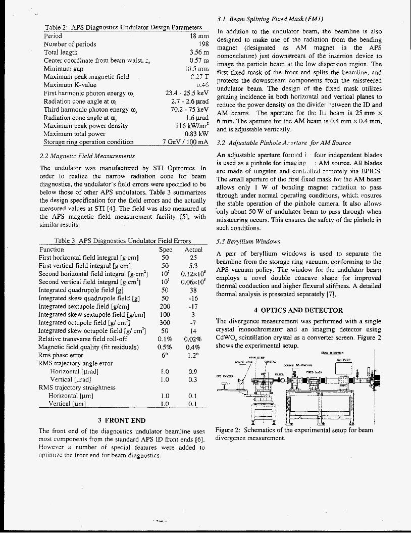
Table 2: APS Diagnostics Undulator Design Parameters Period 18 mm Number of periods 198 Total length 3.56 m Center coordinate from beam uaist, z0 0.57 m Minimum gap I O 5 mm Maximum peak magnetic field C 27 T Maximum K-value 0.45 First harmonic photon energy w, 23.4 - 25.5 keV Radiation cone angle at a, 2.7 - 2.6 p a d Third harmonic photon energy q 70.2 - 75 keV Radiation cone angle at q 1.6 p a d Maximum peak power density 1 16 kW/mr2 Maximum total power 0.83 kW Storage ring operation condition 7 GeV / 100 mA
2.2 Magnetic Field Measurements
The undulator was manufactured by STI Optronics. In order to realize the narrow radiation cone for beam diagnostics, the undulator’s field errors were specified to be below those of other APS undulators. Table 3 summarizes the design specification for the field errors and the actually measured values at STI [4]. The field was also measured at the APS magnetic field measurement facility [ 5 ] , with similar results.
Table 3: APS Diagnostics Undulator Field Errors Function Spec Actual First horizontal field integral [ g a n ] 50 25
Second horizontal field integral [gan’] 10’ 0.12~10’ Second vertical field integral [gem'] 10’ 0.06~10’ Integrated quadrupole field [g] 50 38
First vertical field integral [gcm] 50 5.3
Integrated skew quadrupole field [g] 50 -16 Integrated sextupole field [ & T I ] 200 -17 Integrated skew sextupole field [g/cm] I O 0 3 Integrated octupole field [g/ cm’] 300 -7 Integrated skew octupole field [g/ cm’] 50 14 Relative transverse field roll-off 0.1% 0.02% Magnetic field quality (fit residuals) 0.5% 0.4% Rms phase error 6” 1.2” RMS trajectory angle error
Horizontal [prad] 1 .o 0.9 Vertical [prad] 1 .o 0.3
RMS trajectory straightness Horizontal [pm] 1 .o 0.1 Vertical [pm] I .o 0.1
3 FRONTEND The front end of the diagnostics undulator beamline uses most components from the standard APS ID front ends [6]. However a number of special features were added to optimize the front end for beam diagnostics.
3. I Beam Splitting Fixed Mask (FMI)
In addition to the undulator beam, the beamline is also designed to make use of the radiation from the bending magnet (designated as AM magnet in the APS nomenclature) just downstream of the insertion device to image the particle beam at the low dispersion region. The first fixed mask of the front end splits the beamline, and protects the downstream components from the missteered undulator beam. The design of the fixed mask utilizes grazing incidence in both horizontal and vertical planes to reduce the power density on the divider ietween the ID and AM beams. The aperture for the IZ, beam is 25 mm x 6 mm. The aperture for the AM beam is 0.4 mm x 0.4 mm, and is adjustable vertically.
3.2 Adjustable Pinhole A: grture for AM Source
An adjustable aperture formed i four independent blades is used as a pinhole for imaging 7 AM source. All blades are made of tungsten and contalled re-notely via EPICS. The small aperture of the first fixed mask for the AM beam allows only 1 W of bending magnet radiatioii to pass through under normal operating conditions, whick ensures the stable operation of the pinhole camera. It also allows only about 50 W of undulator beam to pass through when missteering occurs. This ensures the safety of the pinhole in such conditions.
3.3 Beryllium Windows
A pair of beryllium windows is used to separate the beamline from the storage ring vacuum, conforming to the APS vacuum policy. The window for the undulator beam employs a novel double concave shape for improved thermal conduction and higher flexural stiffness. A detailed thermal analysis is presented separately [7].
4 OPTICS AND DETECTOR The divergence measurement was performed with a single crystal monochromator and an imaging detector using CdWO, scintillation crystal as a converter screen. Figure 2 shows the experimental setup.
Btul URECTION
wm PUMP B W DUMP
n s m m u r n R I C R ~ U . - i t I
Figure 2: Schematics of the experimental setup for beam divergence measurement.

. 4.1 Monochromator
A Huber Goniometer is used as the base for the single crystal monochromator. The monochromator crystal, Ge(220), is clamped on a water-cooled copper block. The beam dump is made of GlidCop and is also enclosed in the monochromator chamber which is filled with helium. The monochromatic x-ray goes through an 80-pm aluminum window to reach the imaging detector located in the open air. Such an arrangement significantly reduces ozone generat;>n by the white undulator beam.
4.2 Imaging Detector
The cross section of -iIe monochromatic x-ray beam is imaged with a 0.3-mm-tiiick CdWO, scintillation crystal. A CCD camera with a C-mount photographic lens (f= 75 mm) is used for the image acquisition. The pixel scale of the camera is calibrated with a grid pattern mounted on the background of the scintillator crystal. A Spiricon digitizer (120x120 pixels with 35 pndpixel) is used to record the image.
50297sr7.lba
2000 4WO 6WO
X Iprn!
Figure 3: First image from the APS diagnostics undulator.
5 RESULTS In the first experiment performed at the beamline on May 3, 1997, the undulator gap was set at 16.0 mm, with the first harmonic at 25.5 keV. The monochromator crystal angle was scanned to pass the maximum intensity point and to reach a minimum x-ray beam cross section. The photon energy was estimated to be around 25.7 keV. To simulate users’ running conditions. the images of the x-ray beam were averaged every S frames (over 0.9 second) in the Spiricon. and five averaped images were recorded and examined to evaluate data consistency
.A typical beam image taken at a stored beam current of 65 mA is shown in Fig. 3. Table 4 shows the beam cross section and the inferred particle beam properties based on the design lattice functions. In these calculations, we have not considered the contribution of the imaging detector resolution. mil it.; subtnctinn would likely further reduce
the measured beam emittance. The large error bars assigned to the beam parameters reflect largely the uncertainty of our knowledge about the lattice functions.
Table 4: APS Diagnostics Undulator Divergence Measurement (65 mA stored current)
X-ray beam size (C1xC,) 674x 164 (pm)* Partial emittance (E,xE~,) 6.4 x 0.24 (nm.rad) Total emittance (E) 6.6 f 0.6 (nm.rad) Vertical coupling ( x ) 0.037 kO.004 e-beam size (gxoJ 3 0 0 ~ 50 ( p m t e-beam divergence ((T’,XG’~) 2 1 x 4.9 (pad)
2
6 SUMMARY The APS diagnostics undulator has been commissioned and first results are used to characterize the storage ring beam. Using the design lattice functions, the measured particle beam size, divergence, and emittance are all within design specifications, which in turn translates to higher x-ray beam brilliance than the APS design goal.
7 ACKNOWLEDGEMENTS We wish to thank I. Vasserman for his assistance in undulator field measurements; P. Den Hartog and E. Gluskin for their help in the undulator installation; M. Ramanathan, A. R. Passi, R. W. Nielsen, T. L. Guy, J. Hawkins and N. Friedman for their help in the front end installation; and G. A. Decker and J. N. Galayda for their continued support for the project. This work was supported by U. S. Department of Energy, Office of Basic Energy Sciences under Contract No. W-3 1- 109-ENG-38.
[31
141
[51
REFERENCES E. Tarazona and P. Elleaume, “Emittance measurements at ESRF.” Rev. Sci. Instrum. 66, 1995. Z. Cai, R. J. Dejus, P. Den Hartog, Y. Feng, E.Gluskin, D. Haeffner, P. Illinski. B. Lai, D. Legnini, E. R . Moog, S. Shastri, E. Trakhtenberg, I. Vasserman, and W. Yun, “APS Undulator Radiation - First Results,” Rev. Sci. Instrum. 67, (1996) CD ROM. B. Yang and A. H. Lumpkin, ”The Planned Photon Diagnostics Beamlines at the Advanced Photon Source,” BIW94, AIP Conf. Proc. 333, Oct. 1994. STI Optronics, “Magnetic Certification Data for U18, #14,” 1996, unpublished. L. Burkel, R. Dejus, J . Maines, J. OBrien, J . Pflueger, and I. Vasserman, “The insertion Device Magnetic Measurement Facility: Prototype and Operational Procedures,” ANUAPSRB- 12, 1993. D. Shu, and T. M. Kuzay, “General Layout Design for the Advanced Photon Source Beamline Front Ends,” Nucl. Insrrutn. Meth. A 347, 1994. I. C. Sheng, B. X. Yang, and S. Sharma, “Design and analysis of a Be window for the APS diagnostics undulator beamline.” these proceedings.