Embed Size (px)
DESCRIPTION
LCLS - Undulator Controls WBS 1.04.02. S. Joshua Stein. [UCS] - Design Philosophy. The LCLS Undulator Control System (UCS) will be designed as a stand-along control system with interfaces to the existing SLAC control system. - PowerPoint PPT Presentation
Citation preview
A U.S. Department of EnergyOffice of Science LaboratoryOperated by The University of Chicago
Argonne National Laboratory
Office of ScienceU.S. Department of Energy
LCLS - Undulator ControlsWBS 1.04.02
S. Joshua Stein
2
Pioneering Science andTechnology
Office of Science U.S. Department
of Energy
[UCS] - Design Philosophy
• The LCLS Undulator Control System (UCS) will be designed as a stand-along control system with interfaces to the existing SLAC control system.
• Commercial products will be used whenever possible to avoid duplication of effort and maximize the benefits of product maturity.
• When a novel design is required, all attempts will be made to create a “product” which will be useful in both the LCLS-UCS and the SLAC control system.
3
Pioneering Science andTechnology
Office of Science U.S. Department
of Energy
[UCS] - Resource philosophy
• Whenever possible, APS manpower will be utilized in the design and implementation of the UCS.
• External consultants will be used to help bridge the gap between SLAC and APS and fill in for engineering manpower that APS is unable to supply.- Bob Dalesio (LANL) is currently working with both APS and
SLAC on LCLS control issues. His primary goal is to ease the communication between the different (independent) control systems. In addition, his experience in implementing control systems for multi-laboratory projects make him uniquely qualified in this role.
- Technical design effort will be outsourced as needed from a wide pool of talent in the EPICS community.
4
Pioneering Science andTechnology
Office of Science U.S. Department
of Energy
[UCS] - Schedule and cost estimates
• Whenever possible, real-world experience was used as a basis of estimate for both material and effort costs.
• Using engineering experience from within the APS controls group (who designed and implemented the control system for the APS and LEUTL), initial estimates were gathered from a diverse resource pool.
• Also, consultant effort has been utilized to check and scrub the initial UCS schedule.
• Many controls requirements are still not defined well enough for accurate vendor-based quotations. However, making practical assumptions allowed for creating estimates that we feel are significantly better than a wild guess.
5
Pioneering Science andTechnology
Office of Science U.S. Department
of Energy
[UCS] - Interface with SLAC
• While the UCS will be self-sufficient, there is by necessity a large amount of communication required between the two control systems.- Software
- It is expected that the undulator section will be accessible from anywhere within the LCLS control structure. As such, software interfaces will be designed to accommodate such a requirement, while maintaining the integrity of the individual control systems.
- To leverage the knowledge of the APS controls group staff and minimize unnecessary effort, the EPICS control system platform was chosen for the UCS. EPICS has a proven track record in the accelerator (and FEL) community.
6
Pioneering Science andTechnology
Office of Science U.S. Department
of Energy
[UCS] - Interface with SLAC (timing)
- Timing- Significant effort will be expended in research and design to
assure that timing information from the injector is available to the UCS and diagnostics.
- We envision the design of EPICS compliant timing boards which will reside in both VME and PCI backplanes. These boards will accept the SLC timing messages and output EPICS compatible data for all of the subsystems within the UCS that require timing and time-stamp information.
7
Pioneering Science andTechnology
Office of Science U.S. Department
of Energy
[UCS] - Interface with SLAC (MPS)
- Machine Protection- To protect the undulator components, a machine protection
system (MPS) will be implemented along side the UCS. This system will be responsible for notifying the LCLS injector of a shutdown condition when a (machine oriented) dangerous situation arises.
8
Pioneering Science andTechnology
Office of Science U.S. Department
of Energy
[UCS] - Interface with SLAC (commissioning)
• Our goal is to turn over a completely seamless and operational undulator system to the LCLS. In this regard, as much as possible the control system will be designed, tested and verified at the APS.
• Work done at SLAC should be restricted to commissioning and test.
• Training will have to be done after the commissioning process to allow the operation of the undulator by SLAC personnel.
9
Pioneering Science andTechnology
Office of Science U.S. Department
of Energy
[UCS] - Motion platforms
• Fine Motion- Strongback Cradle
- Current motion platform based on cam movers- Stepper motors with rotary encoders
- Overall effect to move Quadrapoles- Purpose: Beam Steering and tuning within the intra-
undulator space- Position feedback via external sensors (wire position
monitors covered in 1.04.06.01.01 - Undulator alignment)
10
Pioneering Science andTechnology
Office of Science U.S. Department
of Energy
[UCS] - Motion platforms
• Fine Motion- Scanning Wire Transducer
- Using SLAC standard SWA assembly- Stepper motors with rotary encoders- Purpose: Characterize the beam
• Position• Size• Shape
11
Pioneering Science andTechnology
Office of Science U.S. Department
of Energy
[UCS] - Motion platforms
• Rough Motion- Diagnostic Stage Selection
- Translate diagnostic “elevator”- Stepper motors - Purpose: Select which Diagnostic stage (OTR, SWA, “No-
Diagnostic”) is in use at each station- Camera controls
- Adjust Focus and aperture for both OTR and inspection cameras- Stepper motors- Purpose: “Tune” video picture
12
Pioneering Science andTechnology
Office of Science U.S. Department
of Energy
[UCS] - Signal Analysis
• RF BPM [33 in total - one per break section]- Physics design to be done by SLAC
- Detectors (RFBPM)- Front-end electronics (amplification)
- Interface with Timing triggers- Physics requirements will determine ADC resolution and
conversion rate - expected to be 12-14 bits at 40MHz - VME backplane
- High data rates may necessitate individual processors for each BPM.
13
Pioneering Science andTechnology
Office of Science U.S. Department
of Energy
[UCS] - Signal Analysis
• Charge Monitor [1]- Hardware to be designed by SLAC
- Toroid and ICT pair- COTS VME based ADC- Interface with Timing triggers
• Scanning Wire [33]- Hardware to be designed by SLAC
- Mechanical Assembly including motors- COTS VME based ADC- Interface with Timing triggers
14
Pioneering Science andTechnology
Office of Science U.S. Department
of Energy
[UCS] - Video
• OTR Stages [11]- Acquire and analyze beam
- Position- Shape- Size
- 30 Hz capture and analysis rate (1/4 SLAC trigger)- Large FOV requirement at “reasonable” resolution
- Allows digital “zoom”- No need for two camera configuration- Digital interface for frame grabber
15
Pioneering Science andTechnology
Office of Science U.S. Department
of Energy
[UCS] - Video
• OTR Stages (continued)- Provide operator/scientist “warm fuzzy”
- Rough beam alignment- Requires video mux and routing via UCS
• Observation video [7]- Color “analog” cameras for visual inspection only- To be integrated in video mux system from OTR stations.
16
Pioneering Science andTechnology
Office of Science U.S. Department
of Energy
[UCS] - Temperature monitoring
• Two thermal sensors per each strongback- Used for low data-rate trend analysis and alarms
17
Pioneering Science andTechnology
Office of Science U.S. Department
of Energy
[UCS] - Vacuum control
• Pump controller interface to control system- Whenever possible, commercial pump controllers will be
purchased with standard communications protocols (Serial, Ethernet, etc.).
• Vacuum gauges- Whenever possible, commercial gauges will be purchased with
standard communications protocols (Serial, Ethernet, etc.).
• RGA- Typically, these devices use embedded PCs as both a user
interface and data acquisition unit. Integrating these into the UCS will most likely be done via Ethernet based function calls.
• Vacuum Valve- Position monitoring only via binary inputs from limit switches.
18
Pioneering Science andTechnology
Office of Science U.S. Department
of Energy
[UCS] - Software
• Control software will be run on the EPICS ‘platform’- Defines a low level control schema and implies higher-level
software.
• Whenever possible, existing software will be utilized- Software maturity is an important part of creating a stable
control system.
• High level tools will be installed or written to allow flexible ‘science’ software and support the LCLS community as much as possible without compromising the UCS.- Correlated and consistent operator screens- Data archiving- External software hooks
19
Pioneering Science andTechnology
Office of Science U.S. Department
of Energy
[UCS] - Machine Protection System (MPS)
• Scope needs to be fully defined before details extracted
• Must interface with SLAC to inhibit beam trigger
• Local (inter-undulator) machine protection may include:- Cherenkov detectors- Motion limit detectors- Vacuum
- Pressure- Gas detection- Valve position
20
Pioneering Science andTechnology
Office of Science U.S. Department
of Energy
[UCS] - Machine Protection System (MPS)
• System must be independent of the UCS- Regardless of response time of UCS, MPS must be able to
shutdown beam within specified parameters.
• Current estimates based off of ‘standard’ MPS components within the APS and take into consideration:- I/O types- Number of channels- Response time
21
Pioneering Science andTechnology
Office of Science U.S. Department
of Energy
[UCS] - Design documentation
• It is important to create and maintain system documentation from the beginning of the design process to avoid the “as built” syndrome.
• In particular, all installed hardware and software will be logged and tracked via ‘live’ tools such as the APS developed IRMIS suite.- Maintain an integrated, comprehensive and searchable
database of:- Installed hardware- Control software- Cable- And all interconnections…

22
Pioneering Science andTechnology
Office of Science U.S. Department
of Energy
[UCS] - Cost and Schedule
• Undulator controls initial scrub schedule completely integrated within LCLS overall WBS.- Notable Milestones
- Cradle motion controls complete : February 2005- RF BPM controls complete : March 2007- OTR Video capture and analysis complete : June 2005
• Material and Effort numbers within reasonable bounds for TPC- Total Cost : $4.78M- Total Effort : 5.3 FTE
23
Pioneering Science andTechnology
Office of Science U.S. Department
of Energy
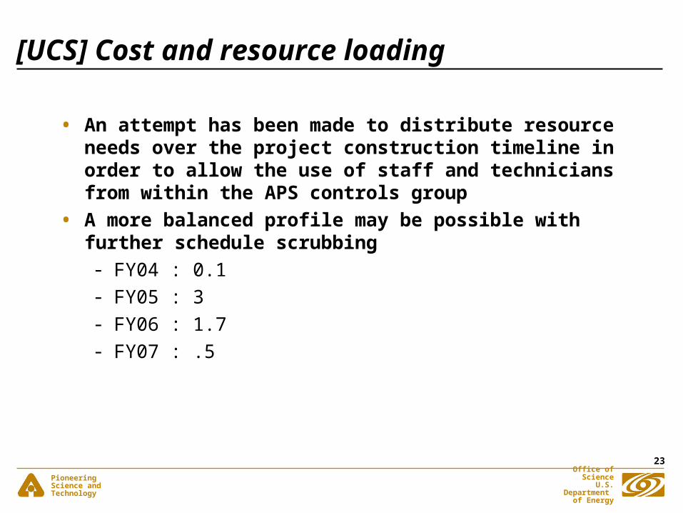
[UCS] Cost and resource loading
• An attempt has been made to distribute resource needs over the project construction timeline in order to allow the use of staff and technicians from within the APS controls group
• A more balanced profile may be possible with further schedule scrubbing- FY04 : 0.1 - FY05 : 3- FY06 : 1.7- FY07 : .5