Embed Size (px)
Citation preview

Written in Feb, 2010
User’s manual
for Generator Control Unit
GCUⓇ(GENERATOR CONTROL UNIT)
MODEL : DG4
Table of Contents◈ ◈
1. Outline ....................................................................................... 3
2. Product Features ........................................................................ 3
3. Specification and Functions ........................................................ 3
4. Conditions of Use ...................................................................... 3
5. Functions of Control Switches ..................................................... 4
6. Structure .................................................................................... 7
7. Preparations before Use ............................................................. 7
8. Regulator ................................................................................... 12
9. Connection sockets and capacity ................................................ 14
10. Signals and Marks .................................................................... 14
11. Manual Operation ..................................................................... 15
12. Automatic Operation ................................................................. 15
13. Engine Generator Protection Device Operation Test ( Identical for
Both Manual and Automatic Operation ) ................................... 16
14. Modification of Environment Settings ......................................... 18
15. List of Option Settings ............................................................. 19
16. Specification Table for GCU-DG4 Compatible Gauge Sensor ...... 26
17. Number of Ring Gears in Major Engines in the World ............... 26
18. Cause of Breakdown and Solutions ........................................... 27
ENGINE GENERATOR CONTROL ENTERPRISE
EGCON CO., LTDhttp://www.egcon.co.kr [email protected]
TEL: 032-677-9806 FAX: 032-677-9807
GCU -DG4 Manual EGCON CO., LTD
Cautions for your safety1. Please be well informed of user’s manual and drawings of the product in order to operate safely
2. Please follow all safety instructions to prevent potential accidents and dangers
3. There are two types of cautions; “Warning” and “Caution”, where each meaning are as follow:
Warning
Potential injury or death
may arise in case of
violation of safety
instructions
Caution
Potential injury or product
damage may arise in
case of violation of safety
instructions
4. Meanings of picture signals appear in the manuals are as follow:
Please be careful as it may cause
product damage
Please be careful as it may cause
electrocution
5. Please keep this manual close to the product
1. Please do not perform wiring work when power is on or in
operation as it may cause electrocution.
2. Please do not disassemble the product even when power is off,
as the charging current inside the product may still cause
electrocution.
3. Please do not touch with wet hands as it may cause electrocution.
4. Please do not touch when sheath of electric wire is damaged as it may cause
electrocution.
5. Please do grounding of electric wire to prevent electrocution.
Warning
1. Please permit a correct power supply to prevent product damage
and fire
2. Please be sure no foreign substances enter into the product as
they may cause short circuit or fire.
3. Please connect wire with correct load to input and output sockets to prevent product
damage and fire.
4. Please connect wire as instructed to prevent product damage and fire.
5. Only technicians or properly trained personnel may use this product as irrational use of this
product may cause injuries or damages to the product and devices connected to the
product.
6. As this product comprises of electrical components, please separate the product before
performing the test which requires high voltage such as inner voltage test or insulation
resistance test.
7. Please use fuse and electric wire with correct capacity to prevent fire.
8. Please hold this product firmly as it is used for engine generator with high vibration.
9. Please make sure there are no untangled parts before installation.
Caution
GCU -DG4 Manual EGCON CO., LTD
1. Outline
GCU-DG4 is a diesel engine generator controller with digital instrumentation function and digital
protective relay.
2. Product Features
2.1. Increased visibility with larger display
2.2. Easy to use with simplified and condensed setting
2.3. Digital protective relay function (OVR, OCR, UVR)
2.4. RPM, OPG, WTG, DCV, ETM gauges and OTG for Korean use
2.5. Ability to use commercial power or non-electrical interface with automatic operating signal
2.6. Over speed, over current test switch
2.7. Engine warm-up plug for small engine
2.8. Warning alert sound.
2.9. Stop Solenoid anti burn out design
2.10. High-capacity relay interface for start, stop (15A), ACB input, and block (15A)
3. Specification and Functions
3.1. Control power supply: 8 ~ 35Vdc, Power consumption: Below 5W on idle, 360W maximum
3.2. Speed sensor: MPU detection 0 ~ 7,000 Hz , 3 ~ 20 Vac
3.3. Commercial power detection: Max. 500Vac, 3 sides 4 lines and platform
3.4. Automatic operation signal: Selection between non-electrical interface and commercial power
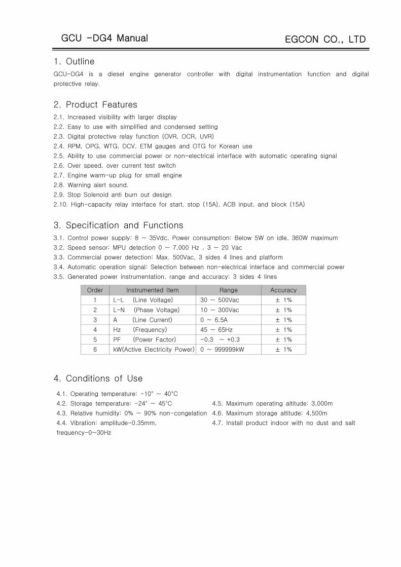
3.5. Generated power instrumentation, range and accuracy: 3 sides 4 lines
Order Instrumented Item Range Accuracy
1 L-L (Line Voltage) 30 ~ 500Vac ± 1%
2 L-N (Phase Voltage) 10 ~ 300Vac ± 1%
3 A (Line Current) 0 ~ 6.5A ± 1%
4 Hz (Frequency) 45 ~ 65Hz ± 1%
5 PF (Power Factor) -0.3 ~ +0.3 ± 1%
6 kW(Active Electricity Power) 0 ~ 999999kW ± 1%
4. Conditions of Use
4.1. Operating temperature: -10° ~ 40°C
4.2. Storage temperature: -24° ~ 45°C
4.3. Relative humidity: 0% ~ 90% non-congelation
4.4. Vibration: amplitude-0.35mm,
frequency-0~30Hz
4.5. Maximum operating altitude: 3,000m
4.6. Maximum storage altitude: 4,500m
4.7. Install product indoor with no dust and salt
GCU -DG4 Manual EGCON CO., LTD
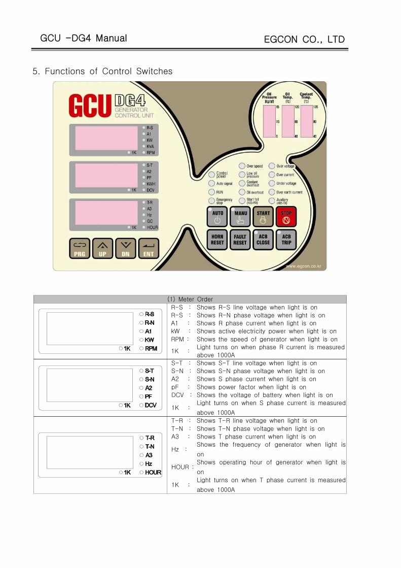
5. Functions of Control Switches
(1) Meter Order
R-S : Shows R-S line voltage when light is on
R-S : Shows R-N phase voltage when light is on
A1 : Shows R phase current when light is on
kW : Shows active electricity power when light is on
RPM : Shows the speed of generator when light is on
1K :Light turns on when phase R current is measured
above 1000A
S-T : Shows S-T line voltage when light is on
S-N : Shows S-N phase voltage when light is on
A2 : Shows S phase current when light is on
pF : Shows power factor when light is on
DCV : Shows the voltage of battery when light is on
1K :Light turns on when S phase current is measured
above 1000A
T-R : Shows T-R line voltage when light is on
T-N : Shows T-N phase voltage when light is on
A3 : Shows T phase current when light is on
Hz :Shows the frequency of generator when light is
on
HOUR :Shows operating hour of generator when light is
on
1K :Light turns on when T phase current is measured
above 1000A

GCU -DG4 Manual EGCON CO., LTD
(2) Operation Switches (3) Setup Switches
Sets to automatic operating mode
(When the button is pushed the light
turns on and sets to automatic mode)
Stop mode and manual mode. You can
change settings when generator is
stopped.
Sets to manual operating mode (When
the button is pushed the light turns on
and sets to manual mode)
Increase setting value. Check values on
measurement screen when in operation
Generator starter switch upon manual
mode
Decrease setting value. Check values
on measurement screen when in
operation
Generator stop switch upon manual
modeSave and quit
Buzzer stop switch when breakdown
detected. Function of LAMP TEST upon
OFF mode
Breakdown reset button
Input of circuit breaker when on manual
mode. Flicker is on during waiting time
for the input on automatic mode
Block circuit breaker when on manual
mode. Flicker is on during waiting time
for the block on automatic mode

GCU -DG4 Manual EGCON CO., LTD
(4) Engine Gauge (5) Lamp
Oil Pressure Gauge (OPG)
range of 0 ~ 15 /㎏ ㎠
Control Power : Light Turns on upon DC power
input
Automatic
Signal :
Light turns on when commercial
power is normal. Flicker is on
during waiting time for starting and
cooling-off period.
Operation : Light turns on when generator is
operating
Emergency Stop
:
Light turns on upon input of
emergency stop
Oil Temperature Gauge
(OTG) range of 40~120℃
Over Speed : Light turns on upon excessive
speed. Flicker is on during the
detection of excessive speed
breakdown.
Low Oil
Pressure :
Light turns on upon low oil
pressure. Flicker is on during the
detection of low oil pressure.
High
temperature of
Coolant :
Light turns on upon high
temperature of coolant. Flicker is
on during the detection of
excessive temperature of coolant.
Excessive
Temperature of
Lubricant :
Light turns on upon excessive
temperature of lubricant. Flicker is
on during the detection of
excessive temperature of lubricant.
Start Failure : Light turns on when excessive
voltage relay is in operation. Flicker
is on during the detection of
excessive current.
Coolant(Water)
Temperature Gauge (WTG)
range of 40 ~ 120℃
Over voltage : Light turns on when excessive
voltage relay is in operation. Flicker
is on during the detection of
excessive voltage.
Over current : Light turns on when excessive
current relay is in operation. Flicker
is on during the detection of
excessive current.
Low Voltage : Light turns on when low current
relay is in operation. Flicker is on
during the detection of low voltage.
Grounding : Light turns on upon grounding relay
is in operation.
Preparation : Light turns on upon input of
reserve breakdown detection.
GCU -DG4 Manual EGCON CO., LTD
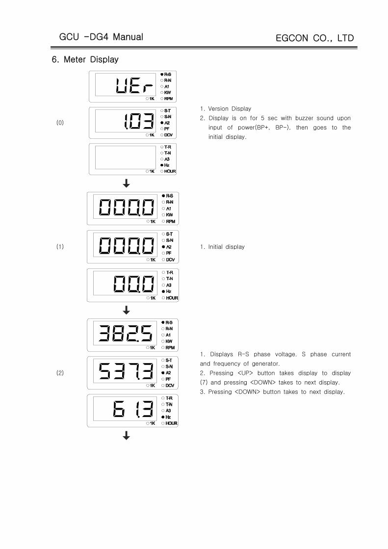
6. Meter Display
(0)
1. Version Display
2. Display is on for 5 sec with buzzer sound upon
input of power(BP+, BP-), then goes to the
initial display.
(1) 1. Initial display
(2)
1. Displays R-S phase voltage. S phase current
and frequency of generator.
2. Pressing <UP> button takes display to display
(7) and pressing <DOWN> takes to next display.
3. Pressing <DOWN> button takes to next display.

GCU -DG4 Manual EGCON CO., LTD
(3)1. Displays line voltage of generator.
(4)1. Displays phase voltage of generator.
(5) 1. Displays current of generator.

GCU -DG4 Manual EGCON CO., LTD
(6) 1. Displays current of generator.
(7)
1. Displays speed of revolution, operation hours of
the generator and battery's voltage.
2. Every number in First decimal place of the
operation hours indicates 6 min.
3. Pressing <UP> button takes to the prior display.
4. Pressing <DOWN> button takes to display (3).

GCU -DG4 Manual EGCON CO., LTD
7. Structure
7.1. Dimension : W240 * H172 * D58 (mm).
7.2. Cut-out : W211 * H162(mm)
7.3. Mounting Holes : W226 * H60(mm), 6pi -4H
7.4. Weight : About 1.2kg (including case)
7.5. Outward drawing
8. Preparation before use
8.1 Connect circuits into input/output sockets of GCU-DG4 referring to circuit diagram 1 and 2.
회로도[ 1 ]

GCU -DG4 Manual EGCON CO., LTD
Warning
Voltage of power supply and current has to be identical to avoid voltage
indication error.
CNT socket need not be connected when directly inputting commercial
power for detection of power outage signal.
[ Circuit Diagram 2 ]
8.2 Please adjust settings of GCU-DG4 to fit the generator
Caution
If settings are adjusted differently from the generator problems will arise during
the operation. Especially with wrong [8 GEAR] setting, human accident may
arise due to the failure to detect excessive speed. Please be sure to inquire the
manufacturer of the engine the number of ring gear.

GCU -DG4 Manual EGCON CO., LTD
Settings▶
[1. ENGINE SET Switch] --> [ 5. OTU ] : Whether to use oil temperature gauge
[ 6. COM PWR ] : Whether to directly connect commercial power
[ 7. Method of detecting generator speed ] : VOLT, MPU
- VOLT : Detect generator speed from voltage of generator
- MPU : Detect generator speed using Magnet Pick Up sensor
[ 8. Engine operation method ] : ETS, ETR
[2. CT RATIO ] : CT setting
CT Ratio 1, CT Ratio 2, CT Ratio 3 usage setting
When using CT 1000/5 : CT Ratio 1 - 2, CT Ratio 2 - 0, CT Ratio 3 - 0 setting
Set values by Dividing CT 1000 by 5
When CT setting is different it displays different current value and voltage value
[3. OPT, WTG gauge setting ] --> set according to the settings menu
9. Regulator
9.1. TEST SW : Breakdown test button set to breakdown test selection
When this button is pressed it becomes the selected breakdown test regardless the actual breakdown
9.2. TIMER DIP S/W
DIP S/W number 1 2 3 4
Waiting time
for starting
○ ○ 3 Sec
○ ● 5 Sec
● ○ 10 Sec
● ● 30 Sec
Waiting time
for engine cool down
○ ○ 10 Sec
○ ● 30 Sec
● ○ 1 Min
● ● 3 Min
DIP S/W number 5 6 7 8
Waiting time for block
circuit breaker
○ ○ 3 Sec
○ ● 5 Sec
● ○ 10 Sec
● ● 30 Sec
Waiting time for input
of circuit breaker
○ ○ 3 Sec
○ ● 5 Sec
● ○ 10 Sec
● ● 30 Sec
: DIP S/W OFF, : DIP S/W ON○ ●

GCU -DG4 Manual EGCON CO., LTD
9.3. CT Settings
When using 1000/5 :●
Set CT Ratio 1 - 2, CT Ratio 2 - 0, CT Ratio 3 - 0 by dividing 1000 by 5.
When using 300/5 CT :●
Set CT Ratio 1 - 0, CT Ratio 2 - 6, CT Ratio 3 - 0 by dividing 300 by 5.
9.4. ENGINE SET DIP S/W
DIP S/W
OrderFunction Description
1UVR
(Low Voltage Relay)
● Generator Stop
○ Generator in operation
2OCR
(Over Current Relay)
● Generator Stop
○ Generator in operation
3GR
(Grounding Relay)
● Generator Stop
○ Generator in operation
4AFR
(Reserve Breakdown Input)
● Generator Stop
○ Generator in Operation
5
OTU
(Lubricant temperature
gauge)
● Use oil temperature gauge
○ Do not use oil temperature gauge
6COM PWR
( Commercial Power )
● Use commercial power outage detection
○ Use commercial power outage detection
7
VOLT ● Detect generator RPM with voltage
MPU ○ Detect generator RPM with MPU
8
ETS ● ETS : Supply power to solenoid upon stop
ETR ○ETR : Supply power to solenoid during
operation
: DIP S/W OFF, : DIP S/W ON○ ●

GCU -DG4 Manual EGCON CO., LTD
9.5. RUN SET
DIP S/W Order 1 2 3 4
Waiting time for
start stabilization
○ ○ 5 Sec
○ ● 10 Sec
● ○ 15 Sec
● ● 20 Sec
Breakdown Test
Selection
○ ○ OSS-T(Over Speed)
○ ● OVR-T(Over Voltage)
● ○ UVR-T(Under Voltage)
● ● OCR-T(Over Current)
10. Connection Terminals and Capacity
Terminals Name Description Rated Capacity
BP+, BP- Input of control power DC 8~35V , 15A
88x Start output BP+ voltage output, Max 15A
5x Stop output BP+ voltage output, Max 15A
23x Preheating output BP+ voltage output, Max 15A
COM-U, COM-V Input of commercial power 1/2W, 220Vac
GEN-R,S,T,N Input of generator power 3P4W, 380/220Vac
IA-K, CT-LInput of L, K of R in generator
CT5Aac
IB-K, CT-LInput of L, K of S in generator
CT5Aac
IC-K, CT-LInput of L, K of T in generator
CT5Aac
52-COM, 52TX-a ACB blocking interface Dry contact , AC250V, 15A (2sec)
52-COM, 52CX-a ACB blocking interface Dry contact, AC250V, 15A (2sec)
86X-c, 86X-a Breakdown display interface Dry contact , AC250V, 10A
6X-c, 6X-a Engine operation display interface Dry contact , AC250V, 10A
WTS Input of high temperature switch NORMAL OPEN , connect DC-
OPS Input of oil pressure switch NORMAL CLOSE, connect DC-
EPB Input of emergency stop switch NORMAL OPEN , connect DC-
OCGR Input of over voltage relay NORMAL OPEN , connect DC-
AFR Input of potential breakdown NORMAL OPEN , connect DC-
52-ON, 52-OFF Input of ACB block signal Connect DC-
CNT Automatic operation interfaceOperate when connecting DC- in AUTO
mode
MPU+, MPU- Input of magnetic pickup(MPU) Shiel cable must be grounded
OPU Input of oil pressure sensor Use VDO oil pressure sensor
WTU Input of coolant temperatureVDO and Dongnam Corporation, please
refer to the standard
OTU Input of oil temperature sensorVDO and Dongnam Corporation, please
refer to the standard

GCU -DG4 Manual EGCON CO., LTD
11. Signals and Marks
GCU : GENERATOR CONTROL UNIT
ETS : Supplying power to solenoid when stopped
ETR : Supplying power to solenoid when in operation
86X : Breakdown indicating relay
6X : Operation indicating relay
23X : Preheating relay
52G : ACB
SM : Starting motor
PS : Pinion solenoid
88 : Start assistant magnet
IDLE SPEED : Lowest speed of engine without the
assistance of engine starting motor
MPU : MAGNETIC PICKUP
RPM : Rotating speed indicator
5S : Stop solenoid
88X : Start output relay
EPB : Emergency stop button
OPU : Oil pressure sensor
OTU : Oil temperature sensor
WTU : Coolant temperature sensor
OPS : Oil pressure switch
WTS : Coolant temperature switch
12. Manual Operation
12.1. Set to manual mode by using manual selection button.
12.2. Press start button to start engine
(1) Check engine stop method if only starting motor operates and engine does not start.
(2) When engine starts it displays RPM and oil pressure measurement in OPG
(3) If actual engine speed differs from RPM please stop the engine and correctly input value in
environment setting menu <8. >. (The number of ring gear depends on the manufacturer of
engine)
(4) Starter motor circuit is blocked above IDLE SPEED
(5) When starting engine the starter motor rotates for the duration set in <12. > even with no
IDLE SPEED signal input.
(6) If engine operates normally and IDLE SPEED signal is entered RUN lamp will be lit and 6X will be in
operation
(7) If oil pressure detected during IDLE SPEED and waiting time for start stabilization is below the oil
pressure entered in environment setting menu <2. >, engine will stop and detect low oil pressure
breakdown.
(8) If there is no IDLE SPEED signal and oil pressure switch is working, the starter motor output will be
blocked and engine will operate normally.
12.3. Engine stop
(1) Engine will stop upon pressing stop button
(2) Engine will stop when pressed EPB or engine protection circuit(over speed, over temperature, low oil
pressure) or protection circuit(OVR) is in operation while the engine is operating normally.
- Operating output is blocked immediately when engine is stopped in ETR
- Stoppage output is blocked after the duration entered in environment setting menu <13. > in
ETS. If engine does not stop due to stoppage output is too short, adjust the stoppage output time and
re-test.
13. Automatic Operation
13.1. Set operation mode to <ATO>

GCU -DG4 Manual EGCON CO., LTD
13.2 When commercial power is in outage engine (CNT socket CLOSE) operates after waiting time for
the start.
13.3 When commercial power is in outage and it is returned before SDT time, engine will not start and
SDT time will be initialized.
13.4 When commercial power is in outage, battery “+” output will come from 23X (engine preheating
output) and will be blocked above IDLE SPEED.
13.5 When start output does not reach IDLE SPEED, GCU repeats starting for the duration of time
entered in <12. >. If not starting after third try it recognizes as engine breakdown and stops
starting engine.
13.6 RUN LAMP is on when engine operates normally.
13.7. When there is normal detection of generated power supply ACB will be input after waiting time.
13.8. When commercial power is returned (CNT socket OPEN) during normal operation of engine, engine
will stop after blocking ACB and preparing for re-outage during the waiting time of engine cool down.
13.9. If commercial power is in outage (CNT socket CLOSE) while engine cools down, engine cool down
time will be initialized and ACB will be input immediately.
14. Engine Generator Protection Device Operation Test(Identical for Both
Manual and Automatic Operation)
14.1. Operates in the case of breakdown and warning ( When protection device is in operation, it is▶
possible to RESET only after performing buzzer stop).
14.2 EPB ( EMERGENCY PUSH BUTTON ) Emergency stop test
(1) Check if engine starts, RUN lamp of GCU is on and check whether correct RPM is showing.
(2) Push EPB.
(3) Emergency stop lamp and buzzer sound will be on and engine will stop.
(4) Press buzzer stop, release EPB and press RESET.
14.3. Over speed test ( OVER SPEED )
▶ Since it is dangerous to increase engine RPM, perform test by changing the over speed
detection value.
▶ Change OVER SPEED value below the normal speed in setting menu <1. >. By doing
this, GCU will recognize the normal speed as over speed. Be sure to bring values back to
normal after the test.
▶ Test by pressing over speed test switch
(1) Start engine.
(2) Check if RUN lamp of GCU is on and RPM.
(3) Recognizes over speed and over speed lamp blinks during the waiting time for setting. After waiting
time for setting over speed lamp will be on, buzzer will sound and engine will stop.
(4) By pressing buzzer stop and performing RESET, it brings back to normal.
14.4 Low oil pressure test ( OPS - LOW OIL PRESSURE )
(1) When setting with oil pressure switch:
1) Start engine.
2) Check if RUN lamp of GCU is on and RPM.

GCU -DG4 Manual EGCON CO., LTD
3) Ground OPS socket.
4) Low oil pressure lamp will blink during the setting time and after the setting time oil pressure lamp
will be on, buzzer will sound and engine will stop.
5) Press buzzer stop and RESET.
(2) When setting with oil pressure sensor
1) Start engine.
2) Check if RUN lamp of GCU is on and RPM.
3) Ground OPS socket.
4) Low oil pressure lamp will blink during the setting time and after the setting time oil pressure lamp
will be on, buzzer will sound and engine will stop.
5) Press buzzer stop and RESET.
14.5. Coolant over temperature test ( WTS - HIGH WATER TEMPERATURE )
(1) When setting with over temperature switch
1) Start engine.
2) Check if RUN lamp of GCU is on and RPM.
3) Ground WTS socket.
4) Coolant over temperature lamp will blink during the setting time and after the setting time coolant
over temperature lamp will be on, buzzer will sound and engine will stop.
5) Press buzzer stop and RESET.
(2) When setting with temperature sensor
1) Start engine.
2) Check if RUN lamp of GCU is on and RPM.
3) Ground WTU socket.
4) Coolant over temperature lamp will blink during the setting time and after the setting time coolant
over temperature lamp will be on, buzzer will sound and engine will stop.
5) Press buzzer stop and RESET.
14.6 Lubricant over temperature test ( WTS - HIGH WATER TEMPERATURE )
1) Start engine.
2) Check if RUN lamp of GCU is on and RPM.
3) Ground OTU socket.
4) Coolant over temperature lamp will blink during the setting time and after the setting time coolant
over temperature lamp will be on, buzzer will sound and engine will stop.
5) Press buzzer stop and RESET.
14.7 Start failure test ( OVER CRANKING [ operating only in automatic mode ] )
1) Change to automatic mode and make sure engine does not start.
2) Cut commercial power or ground CNT socket.
3) Start output after SDT time.
4) OCL lamp will be on and buzzer will sound after repeating 7-second start and 7-second stop three
times.
5) LCD display will show OVER CRANK ERROR_MESSAGE.
6) Press buzzer stop and RESET.
7) Remove the setting which made engine not to start and bring settings back to normal.

GCU -DG4 Manual EGCON CO., LTD
14.8 The rest failure tests are similar as above.
15. Modification of Environment Settings
15.1. Change of Environment Setting Mode
(1)1. Press PRG button when generator(in
stop mode or manual mode) is stopped.
2. Takes you settings mode.
(2)1. Settings mode
2. Over speed setting mode
(3) 1. When setting is completed, press PRG
again to return to operation display.

GCU -DG4 Manual EGCON CO., LTD
15.2. Description of Environment Settings
(1)
1. Over speed setting menu
2. Number 2100 will blink in the second line of the display when
pressed <ENT>.
3. Change setting value by using <UP> and <DOWN>.
4. Press <ENT>.
5. Number 2 will blink in the third line.
6. Change setting values by using <UP> and <DOWN>.
7. Changed setting will be saved when pressed <ENT>.
8. Over speed setting range 1000 ~ 2500 RPM
9. Waiting time setting range 1 ~ 60 sec
(2)
1. Lubricant pressure setting menu
2. Number 1.5 will blink in the second line of the display when
pressed <ENT>.
3. Change setting values by using <UP> and <DOWN>.
4. Press <ENT>.
5. Number 2 in the third line of the display will blink.
6. Change setting values by using <UP> and <DOWN>.
7. Changed setting will be saved when pressed <ENT>.
8. Oil pressure setting range 0.9 ~ 9.9 /㎏ ㎠
9. Waiting time setting range 1 ~ 60 sec
(3)
1. Lubricant temperature setting menu
2. Number 110 will blink in the second line of the display when
pressed <ENT>
3. Change setting values by using <UP> and <DOWN>.
4. Press <ENT>.
5. Number 5 in the third line of the display will blink.
6. Change setting values by using <UP> and <DOWN>.
7. Changed setting will be saved when pressed <ENT>.
8. Oil Temperature setting range 50 ~ 110℃
9. Waiting time setting range 1 ~ 60 sec.

GCU -DG4 Manual EGCON CO., LTD
(4)
1. Over current setting menu.
2. Number 180 will blink in the second line of the display when
pressed <ENT>.
3. Change setting values by using <UP> and <DOWN>.
4. Press <ENT>.
5. Number 5 in the third line of the display will blink.
6. Change setting values by using <UP> and <DOWN>.
7. Changed setting will be saved when pressed <ENT>.
8. Over current setting range 50 ~ 110℃
9. Waiting time setting range 1 ~ 60 sec.
(5)
1. Over voltage setting menu.
2. Number 245 will blink in the second line of the display
when pressed <ENT>
3. Change setting values by using <UP> and <DOWN>
4. Press <ENT>
5. Number 5 in the third line of the display will blink.
6. Change setting values by using <UP> and <DOWN>
7. Changed setting will be saved when pressed <ENT>.
8. Over voltage setting range 90 ~ 300Vac
9. Waiting time setting range 1~60 seconds
(6)
1. Low voltage setting menu
2. Number 180 will blink in the second line of the display
when pressed <ENT>
3. Change setting values by using <UP> and <DOWN>
4. Press <ENT>
5. Number 5 in the third line of the display will blink.
6. Change setting values by using <UP> and <DOWN>
7. Changed setting will be saved when pressed <ENT>.
8. Over voltage setting range 80 ~ 220Vac
9. Waiting time setting range 1~60 seconds

GCU -DG4 Manual EGCON CO., LTD
(7)
1. Over current setting menu
2. Number 180 will blink in the second line of the display
when pressed <ENT>
3. Change setting values by using <UP> and <DOWN>
4. Press <ENT>
5. Number 5 in the third line of the display will blink.
6. Change setting values by using <UP> and <DOWN>
7. Changed setting will be saved when pressed <ENT>.
8. Over current setting range 2.0~ 6.5A
9. Waiting time setting range 1~60 seconds
(8)
1. Ground over current setting menu
2. Number "2.5" will blink in the second line of display when
<ENT> is pressed.
3. Change setting values by using <UP> and <DOWN>
4. Press <ENT>
5. Number "5.0" in the third line of the display will blink.
6. Change setting values by using <UP> and <DOWN>.
7. Changing will complete when <ENT> is pressed.
8. Setting range of ground over current : 0.2 ~ 5.0A
초9. Setting range of waiting time : 0.1 ~ 6.0 .
(9)
1. RS485 communication setting menu
2. Number will blink in the second line of display when
<ENT> is pressed.
3. Change setting value by using <UP> and <DOWN>.
4. Press <ENT>.
5. Number "1" will blink in the third line of display.
6. Change setting value using <UP> and <DOWN>.
7. Changing will complete when <ENT> is pressed.
8. Setting communication speed : - 9600 < >
- 19200 < >
- 38400 < >
9. Setting range of address : 1 ~ 32

GCU -DG4 Manual EGCON CO., LTD
(10)
1. Number of gears setting menu
2. Number 121 will blink in the second line of the display
when pressed <ENT>
3. Change setting values by using <UP> and <DOWN>
4. Changed setting will be saved when pressed <ENT>.
5. Number of gears setting range: 1 ~ 250EA
(11)
1. Control mode setting menu
2. < > will blink in the second line of the display when
pressed <ENT>
3. Change setting values by using <UP> and <DOWN>
4. Changed setting will be saved when pressed <ENT>.
5. < > : ACB control mode
6. < > : MCCB control mode
(12)
1. Oil pressure failure detection method setting menu
2. < > will blink in the second line of the display when
pressed <ENT>
3. Change setting values by using <UP> and <DOWN>
4. Changed setting will be saved when pressed <ENT>.
5. < > : Use oil pressure sensor
6. < > : Use oil pressure switch
7. < > : Use neither
GCU -DG4 Manual EGCON CO., LTD
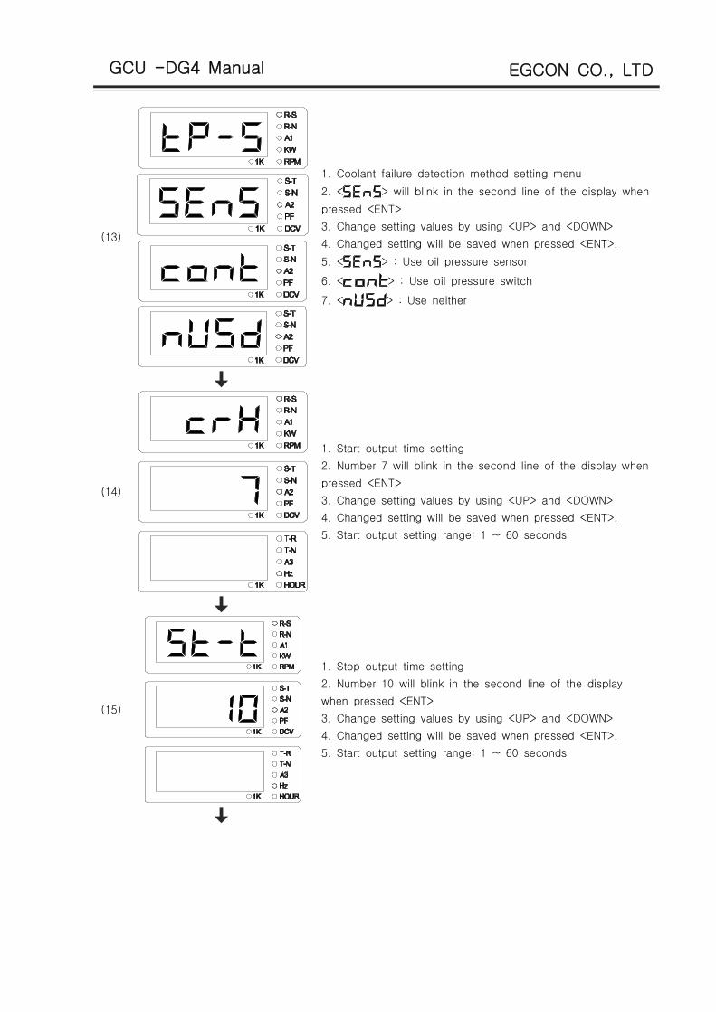
(13)
1. Coolant failure detection method setting menu
2. < > will blink in the second line of the display when
pressed <ENT>
3. Change setting values by using <UP> and <DOWN>
4. Changed setting will be saved when pressed <ENT>.
5. < > : Use oil pressure sensor
6. < > : Use oil pressure switch
7. < > : Use neither
(14)
1. Start output time setting
2. Number 7 will blink in the second line of the display when
pressed <ENT>
3. Change setting values by using <UP> and <DOWN>
4. Changed setting will be saved when pressed <ENT>.
5. Start output setting range: 1 ~ 60 seconds
(15)
1. Stop output time setting
2. Number 10 will blink in the second line of the display
when pressed <ENT>
3. Change setting values by using <UP> and <DOWN>
4. Changed setting will be saved when pressed <ENT>.
5. Start output setting range: 1 ~ 60 seconds
GCU -DG4 Manual EGCON CO., LTD
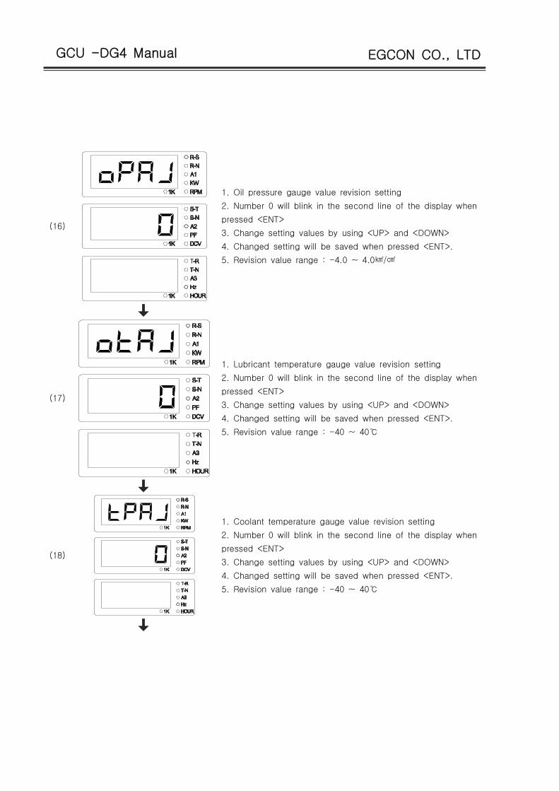
(16)
1. Oil pressure gauge value revision setting
2. Number 0 will blink in the second line of the display when
pressed <ENT>
3. Change setting values by using <UP> and <DOWN>
4. Changed setting will be saved when pressed <ENT>.
5. Revision value range : -4.0 ~ 4.0 /㎢ ㎠
(17)
1. Lubricant temperature gauge value revision setting
2. Number 0 will blink in the second line of the display when
pressed <ENT>
3. Change setting values by using <UP> and <DOWN>
4. Changed setting will be saved when pressed <ENT>.
5. Revision value range : -40 ~ 40℃
(18)
1. Coolant temperature gauge value revision setting
2. Number 0 will blink in the second line of the display when
pressed <ENT>
3. Change setting values by using <UP> and <DOWN>
4. Changed setting will be saved when pressed <ENT>.
5. Revision value range : -40 ~ 40℃

GCU -DG4 Manual EGCON CO., LTD
(19) 1. Menu used when testing in the factory
1. Menu used when testing in the factory
(20)
1. Commercial power low voltage setting menu
2. Number 170 will blink in the second line of the display
when pressed <ENT>
3. Change setting values by using <UP> and <DOWN>
4. Changed setting will be saved when pressed <ENT>.
5. Low voltage setting range : 170 ~ 220Vac

GCU -DG4 Manual EGCON CO., LTD
(21)
1. Commercial power low voltage setting menu
2. Number 170 will blink in the second line of the display
when pressed <ENT>
3. Change setting values by using <UP> and <DOWN>
4. Changed setting will be saved when pressed <ENT>.
5. Low voltage setting range : 170 ~ 220Vac
(22)
1. PT ratio setting menu(for high voltage)
2. < > of second line will blinks when <ENT> key is
pressed.
3. Change setting values by using <UP> and <DOWN>.
4. < > : set when applying 3300 V
- PT ratio uses 3P4W, 3300V-190/ 3√
5. < > : set when applying 6600 V
- PT ratio uses 3P4W, 6600V-190/ 3√
(23) 1. Displays program version

GCU -DG4 Manual EGCON CO., LTD
16. Specification Table for GCU-DG4 Compatible Gauge Sensor
VDO OPU Dongnam Corp. - WTU,OTU
psi bar Impedance Value( )Ω Temp.℃ Impedance Value( )Ω
0 0 10.00 30 170.00
15 1 27.00 35 135.00
30 2 44.00 40 110.00
45 3 61.00 45 92.00
60 4 78.00 50 78.00
75 5 95.00 55 66.00
90 6 112.00 60 56.00
105 7 129.00 65 47.00
120 8 146.00 70 41.00
135 9 163.00 75 35.00
150 10 180.00 80 32.00
165 11 197.00 85 28.03
175 12 208.33 90 24.05
190 13 225.33 95 20.08
205 14 242.33 100 16.10
105 12.10
110 8.10
115 4.10
120 0.10
17. Number of Ring Gears in Major Engines in the World
Engine
ManufacturerEngine Model
Number of
Ring Gears
Engine
ManufacturerEngine Model
Number of
Ring Gears
JOHN DEERE
3179D 142
CATERPILLAR
D399 183
4039D 142 DG399 183
6059T 129 G298 183
6059TA 129 D379 183
PERKINS
2006TWG2 158 G379 183
2006TG2A 158 G342 151
2006TTAG 175 DB58 123
Daewoo Heavy
Industries &
Machinery Ltd
C2240 108 0846 156
DC24 108 D349 151
DB33 122 D348 151
DB58 122 D346 151
DB33 129 D34 152
P034TI 129 3306 156
DB58 129 DE12T(I) 152
D1146(T) 146 G333 156
P86TI 146 D2840L,(E) 160
2156 146 3406 113
2366 146 3409 113
DE12T 152 3412 136
P126TI 152
CUMMINS
NT855G6 118
D2848L,(E) 160 L10 118
D2842L,(E) 160 6BT56G 159
D2840L,(E) 160 4BT39G 159
P158LE 160 KT19G 142
P180LE 160 KT50 159
P222LE 160Hyundai
D6AZ 143
D6BR 129

GCU -DG4 Manual EGCON CO., LTD
18. Cause of Breakdown and Solutions
Symptom Cause Solution
When there is no power (No
vision in LCD display)
DC circuit breaker is open Close DC circuit breaker
DC fuse is disconnected Replace fuse with the same capacity
Wrong wiringCorrect wiring referring to the circuit
diagram
Flat battery Recharge battery at least 5 hours
Cannot start (starter motor is
not working)
Flat battery Recharge battery at least 5 hours
Breakdown of start-assistant
magnetReplace start-assistant magnet
Breakdown of starter motor Replace starter motor
Wrong or no wiring.Correct wiring by referring to the
circuit diagram
When cannot start (starter
motor is working)
Breakdown of pre-heating plug Replace pre-heating plug
Wrong ENGINE TYPE setting in
environment settings
Correctly select ETR and ETS by
inquiring the engine manufacturer
When cannot start (stops
soon after the start)
Wrong PICK-UP SETTING in
environment settings
Correctly enter number of ring gears
by inquiring the engine manufacturer
Wrong or no OPG wiringCorrect wiring by referring to the
circuit diagram
OPG alarm upon the start
Wrong or no OPG wiringCorrect wiring by referring to the
circuit diagram
Wrong OPS MODE setting in
environment settingsCorrectly set OPS MODE
Did not use correct sensor OPU must use products from VDO
Inaccurate RPM of generatorWrong PICK-UP SETTING in
environment settings
Correctly enter number of ring gears
by inquiring the engine manufacturer
No light in GEN. RUN lamp
while generator is in
operation.
Wrong or no wiring of PICK-UPCorrect wiring by referring to the
circuit diagram
Wrong or no wiring of generator
voltage GEN.VOLT socket
Correct wiring by referring to the
circuit diagram
Inaccurate voltage value
Wrong CT RATIO setting in
environment settingsEnter correct CT ratio of CT used
Generator voltage input and CT
input are different
Correct wiring by referring to the
circuit diagram
Indication of power factor is
not normalSecond wiring of CT is wrong
Correct wiring by checking polarity of
CT and referring to circuit diagram
No automatic operation of
generator upon commercial
power outage
Wrong COMP POWER setting in
environment settings
Select whether to receive input of CNT
socket by commercial power outage
signal or by directly detect voltage of
commercial power and arrange
corresponding circuit.
No input of ACBThe generator voltage is
measured lower than UVR value.
Adjust AVR so that generator voltage
is measured normally.