Embed Size (px)
Citation preview
NC8J Series
User’s Manual
NO. G03-NC8J-F
Revision: 2.0
Release date: October 30, 2020
Trademark:* Specifications and Information contained in this documentation are furnished for information use only, and are
subject to change at any time without notice, and should not be construed as a commitment by manufacturer.

i
Environmental Protection Announcement
Do not dispose this electronic device into the trash while discarding. To minimizepollution and ensure environment protection of mother earth, please recycle.

ii
ENVIRONMENTAL SAFETY INSTRUCTION............................................................................. iiiUSER’S NOTICE...............................................................................................................................ivMANUAL REVISION INFORMATION...........................................................................................ivITEM CHECKLIST............................................................................................................................ ivCHAPTER 1 INTRODUCTION OF THE MOTHERBOARD1-1 FEATURE OF MOTHERBOARD.........................................................................................11-2 SPECIFICATION.................................................................................................................... 21-3 LAYOUT DIAGRAM...............................................................................................................3CHAPTER 2 HARDWARE INSTALLATION2-1 JUMPER SETTING................................................................................................................ 82-2 CONNECTORS AND HEADERS........................................................................................ 15
2-2-1 CONNECTORS........................................................................................................152-2-2 HEADERS................................................................................................................ 19
CHAPTER 3 INTRODUCING BIOS3-1 ENTERING SETUP................................................................................................................ 273-2 BIOS MENU SCREEN...........................................................................................................283-3 FUNCTION KEYS...................................................................................................................293-4 GETTING HELP......................................................................................................................293-5 MENU BARS........................................................................................................................... 303-6 MAIN MENU............................................................................................................................ 303-7 ADVANCED MENU................................................................................................................313-8 CHIPSET MENU..................................................................................................................... 443-9 SECURITY MENU.................................................................................................................. 473-10 BOOT MENU...........................................................................................................................493-11 SAVE & EXIT MENU..............................................................................................................51
TABLE OF CONTENT

iii
Environmental Safety Instruction
Avoid the dusty, humidity and temperature extremes. Do not place the product inany area where it may become wet.
0 to 40 centigrade is the suitable temperature. (The temperature comes from therequest of the chassis and thermal solution)
Generally speaking, dramatic changes in temperature may lead to contactmalfunction and crackles due to constant thermal expansion and contraction fromthe welding spots’ that connect components and PCB. Computer should gothrough an adaptive phase before it boots when it is moved from a coldenvironment to a warmer one to avoid condensation phenomenon. These waterdrops attached on PCB or the surface of the components can bring aboutphenomena as minor as computer instability resulted from corrosion and oxidationfrom components and PCB or as major as short circuit that can burn thecomponents. Suggest starting the computer until the temperature goes up.
The increasing temperature of the capacitor may decrease the life of computer.Using the close case may decrease the life of other device because the highertemperature in the inner of the case.
Attention to the heat sink when you over-clocking. The higher temperature maydecrease the life of the device and burned the capacitor.
iv
USER’S NOTICECOPYRIGHT OF THIS MANUAL BELONGS TO THE MANUFACTURER. NO PART OF THIS MANUAL,INCLUDING THE PRODUCTS AND SOFTWARE DESCRIBED IN IT MAY BE REPRODUCED, TRANSMITTEDOR TRANSLATED INTO ANY LANGUAGE IN ANY FORM OR BY ANY MEANS WITHOUT WRITTENPERMISSION OF THE MANUFACTURER.
THIS MANUAL CONTAINS ALL INFORMATION REQUIRED TO USE THIS MOTHER-BOARD SERIES AND WEDO ASSURE THIS MANUAL MEETS USER’S REQUIREMENT BUT WILL CHANGE, CORRECT ANY TIMEWITHOUT NOTICE. MANUFACTURER PROVIDES THIS MANUAL “AS IS” WITHOUT WARRANTY OF ANYKIND, AND WILL NOT BE LIABLE FOR ANY INDIRECT, SPECIAL, INCIDENTAL OR CONSEQUENTIALDAMAGES (INCLUDING DAMAGES FOR LOSS OF PROFIT, LOSS OF BUSINESS, LOSS OF USE OF DATA,INTERRUPTION OF BUSINESS AND THE LIKE).
PRODUCTS AND CORPORATE NAMES APPEARING IN THIS MANUAL MAY OR MAY NOT BEREGISTERED TRADEMARKS OR COPYRIGHTS OF THEIR RESPECTIVE COMPANIES, AND THEY AREUSED ONLY FOR IDENTIFICATION OR EXPLANATION AND TO THE OWNER’S BENEFIT, WITHOUTINTENT TO INFRINGE.
Manual Revision InformationReversion Revision History Date2.0 Second Edition October 30, 2020
Item Checklist Motherboard Cable(s) I/O Back panel shield
1
Chapter 1Introduction of the Motherboard
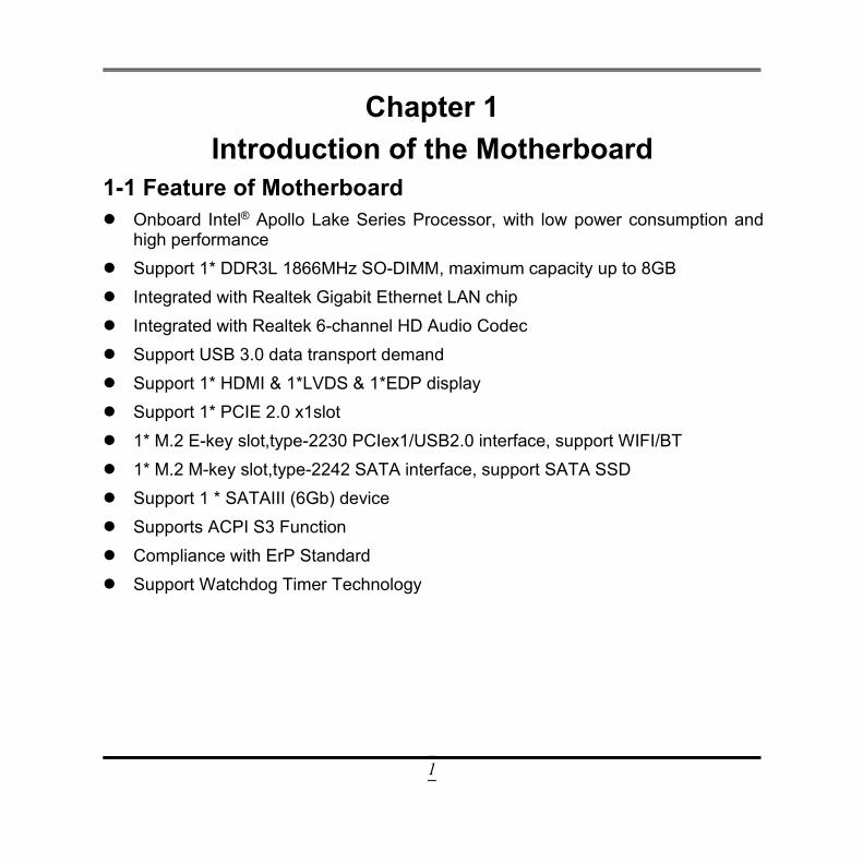
1-1 Feature of Motherboard Onboard Intel® Apollo Lake Series Processor, with low power consumption and
high performance Support 1* DDR3L 1866MHz SO-DIMM, maximum capacity up to 8GB Integrated with Realtek Gigabit Ethernet LAN chip Integrated with Realtek 6-channel HD Audio Codec Support USB 3.0 data transport demand Support 1* HDMI & 1*LVDS & 1*EDP display Support 1* PCIE 2.0 x1slot 1* M.2 E-key slot,type-2230 PCIex1/USB2.0 interface, support WIFI/BT 1* M.2 M-key slot,type-2242 SATA interface, support SATA SSD Support 1 * SATAIII (6Gb) device Supports ACPI S3 Function Compliance with ErP Standard Support Watchdog Timer Technology
2
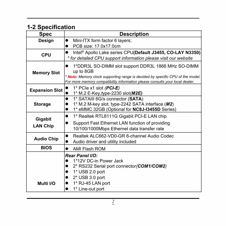
1-2 SpecificationSpec DescriptionDesign Mini-ITX form factor 6 layers;
PCB size: 17.0x17.0cm
CPU Intel® Apollo Lake series CPU(Default J3455, CO-LAY N3350)* for detailed CPU support information please visit our website
Memory Slot 1*DDR3L SO-DIMM slot support DDR3L 1866 MHz SO-DIMM
up to 8GB* Note: Memory clock supporting range is decided by specific CPU of the model.For more memory compatibility information please consults your local dealer.
Expansion Slot 1* PCIe x1 slot (PCI-E) 1* M.2 E-Key,type-2230 slot(M2E)
Storage 1* SATAIII 6G/s connector (SATA) 1* M.2 M-key slot, type-2242 SATA interface (M2) 1* eMMC 32GB (Optional for NC8J-I3455D Series)
GigabitLAN Chip
1* Realtek RTL8111G Gigabit PCI-E LAN chip Support Fast Ethernet LAN function of providing
10/100/1000Mbps Ethernet data transfer rate
Audio Chip Realtek ALC662-VD0-GR 6-channel Audio Codec Audio driver and utility included
BIOS AMI Flash ROM
Multi I/O
Rear Panel I/O: 1*12V DC-in Power Jack 2* RS232 Serial port connector(COM1/COM2) 1* USB 2.0 port 2* USB 3.0 port 1* RJ-45 LAN port 1* Line-out port
3
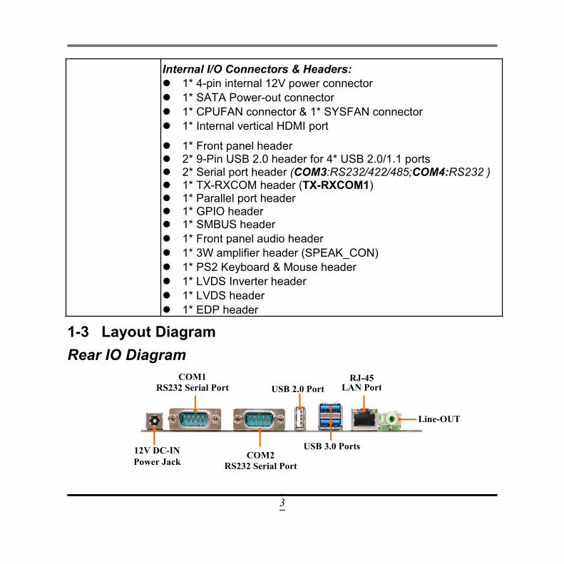
Internal I/O Connectors & Headers: 1* 4-pin internal 12V power connector 1* SATA Power-out connector 1* CPUFAN connector & 1* SYSFAN connector 1* Internal vertical HDMI port
1* Front panel header 2* 9-Pin USB 2.0 header for 4* USB 2.0/1.1 ports 2* Serial port header (COM3:RS232/422/485;COM4:RS232 ) 1* TX-RXCOM header (TX-RXCOM1) 1* Parallel port header 1* GPIO header 1* SMBUS header 1* Front panel audio header 1* 3W amplifier header (SPEAK_CON) 1* PS2 Keyboard & Mouse header 1* LVDS Inverter header 1* LVDS header 1* EDP header
1-3 Layout DiagramRear IO Diagram
COM1RS232 Serial Port
COM2RS232 Serial Port
Line-OUT
12V DC-INPower Jack
USB 2.0 Port
USB 3.0 Ports
RJ-45LAN Port
4
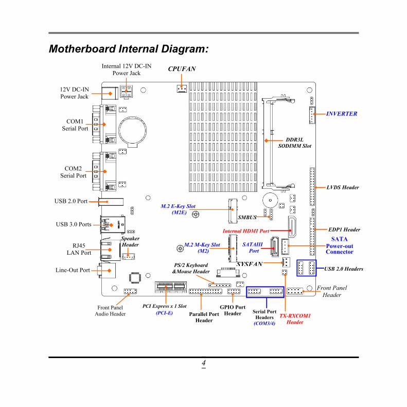
Motherboard Internal Diagram:
PCI Express x 1 Slot(PCI-E)
COM1Serial Port
USB 2.0 Port
COM2Serial Port
USB 3.0 Ports
RJ45LAN Port
Line-Out Port
12V DC-INPower Jack
Internal 12V DC-INPower Jack
DDR3LSODIMM Slot
Front PanelAudio Header
INVERTER
Front PanelHeader
Serial PortHeaders
(COM3/4)
LVDS Header
CPUFAN
M.2 E-Key Slot(M2E)
M.2 M-Key Slot(M2)
Parallel PortHeader
Internal HDMI Port EDP1 Header
GPIO PortHeader
PS/2 Keyboard&Mouse Header USB 2.0 Headers
SATAIIIPort
SATAPower-outConnector
SpeakerHeader
SMBUS
SYSFAN
TX-RXCOM1Header
5
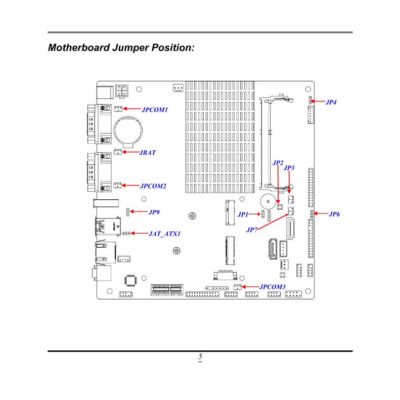
Motherboard Jumper Position:
JPCOM1
JBAT
JP7
JP4
JPCOM2
JP9
JAT_ATX1
JP6
JP3
JP1
JP2
JPCOM3
6
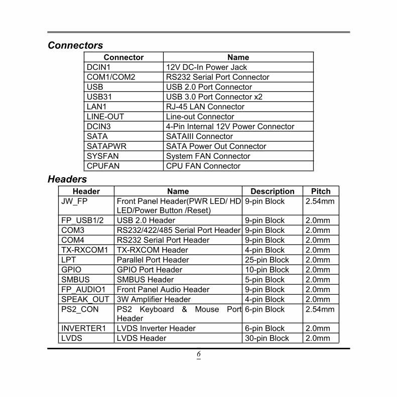
ConnectorsConnector Name
DCIN1 12V DC-In Power JackCOM1/COM2 RS232 Serial Port ConnectorUSB USB 2.0 Port ConnectorUSB31 USB 3.0 Port Connector x2LAN1 RJ-45 LAN ConnectorLINE-OUT Line-out ConnectorDCIN3 4-Pin Internal 12V Power ConnectorSATA SATAIII ConnectorSATAPWR SATA Power Out ConnectorSYSFAN System FAN ConnectorCPUFAN CPU FAN Connector
HeadersHeader Name Description Pitch
JW_FP Front Panel Header(PWR LED/ HDLED/Power Button /Reset)
9-pin Block 2.54mm
FP_USB1/2 USB 2.0 Header 9-pin Block 2.0mmCOM3 RS232/422/485 Serial Port Header 9-pin Block 2.0mmCOM4 RS232 Serial Port Header 9-pin Block 2.0mmTX-RXCOM1 TX-RXCOM Header 4-pin Block 2.0mmLPT Parallel Port Header 25-pin Block 2.0mmGPIO GPIO Port Header 10-pin Block 2.0mmSMBUS SMBUS Header 5-pin Block 2.0mmFP_AUDIO1 Front Panel Audio Header 9-pin Block 2.0mmSPEAK_OUT 3W Amplifier Header 4-pin Block 2.0mmPS2_CON PS2 Keyboard & Mouse Port
Header6-pin Block 2.54mm
INVERTER1 LVDS Inverter Header 6-pin Block 2.0mmLVDS LVDS Header 30-pin Block 2.0mm
7
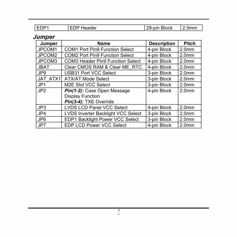
EDP1 EDP Header 29-pin Block 2.0mm
JumperJumper Name Description Pitch
JPCOM1 COM1 Port Pin9 Function Select 4-pin Block 2.0mmJPCOM2 COM2 Port Pin9 Function Select 4-pin Block 2.0mmJPCOM3 COM3 Header Pin9 Function Select 4-pin Block 2.0mmJBAT Clear CMOS RAM & Clear ME_RTC 4-pin Block 2.0mmJP9 USB31 Port VCC Select 3-pin Block 2.0mmJAT_ATX1 ATX/AT Mode Select 3-pin Block 2.0mmJP1 M2E Slot VCC Select 3-pin Block 2.0mmJP2 Pin(1-2): Case Open Message
Display FunctionPin(3-4): TXE Override
4-pin Block 2.0mm
JP3 LVDS LCD Panel VCC Select 4-pin Block 2.0mmJP4 LVDS Inverter Backlight VCC Select 3-pin Block 2.0mmJP6 EDP1 Backlight Power VCC Select 3-pin Block 2.0mmJP7 EDP LCD Power VCC Select 4-pin Block 2.0mm
8
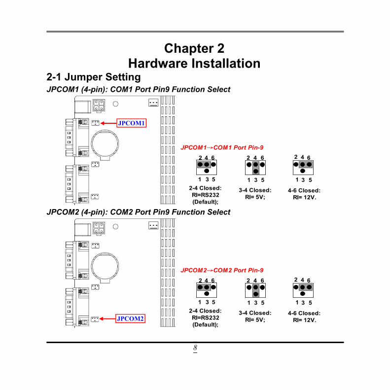
Chapter 2Hardware Installation
2-1 Jumper SettingJPCOM1 (4-pin): COM1 Port Pin9 Function Select
JPCOM1→COM1 Port Pin-9
6 4 2
3 1 5 2-4 Closed: RI=RS232 (Default);
3-4 Closed: RI= 5V;
4-6 Closed: RI= 12V.
1 3 5
2 4 6
5 3 1
2 4 6
JPCOM2 (4-pin): COM2 Port Pin9 Function Select
JPCOM2→COM2 Port Pin-9
6 4 2
3 1 5 2-4 Closed: RI=RS232 (Default);
3-4 Closed: RI= 5V;
4-6 Closed: RI= 12V.
1 3 5
2 4 6
5 3 1
2 4 6
JPCOM1
JPCOM2
9
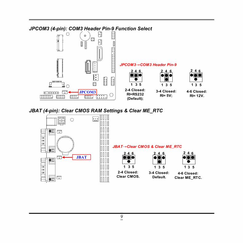
JPCOM3 (4-pin): COM3 Header Pin-9 Function Select
JPCOM3→COM3 Header Pin-9
6 4 2
3 1 5 2-4 Closed: RI=RS232 (Default);
3-4 Closed: RI= 5V;
4-6 Closed: RI= 12V.
1 3 5
2 4 6
5 3 1
2 4 6
JBAT (4-pin): Clear CMOS RAM Settings & Clear ME_RTC
JBAT→Clear CMOS & Clear ME_RTC
6 4 2
3 1 5 2-4 Closed:
Clear CMOS.
3-4 Closed: Default.
4-6 Closed: Clear ME_RTC.
1 3 5
2 4 6
5 3 1
2 4 6
JPCOM3
JBAT
10
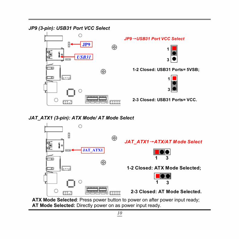
JP9 (3-pin): USB31 Port VCC Select
2-3 Closed: USB31 Ports= VCC.
JP9→USB31 Port VCC Select
1-2 Closed: USB31 Ports= 5VSB;
1
3
1
3
JAT_ATX1 (3-pin): ATX Mode/ AT Mode Select
2-3 Closed: AT Mode Selected.
JAT_ATX1→ATX/AT Mode Select
1-2 Closed: ATX Mode Selected;
1
3 1
3
ATX Mode Selected: Press power button to power on after power input ready;AT Mode Selected: Directly power on as power input ready.
JP9
JAT_ATX1
USB31
11
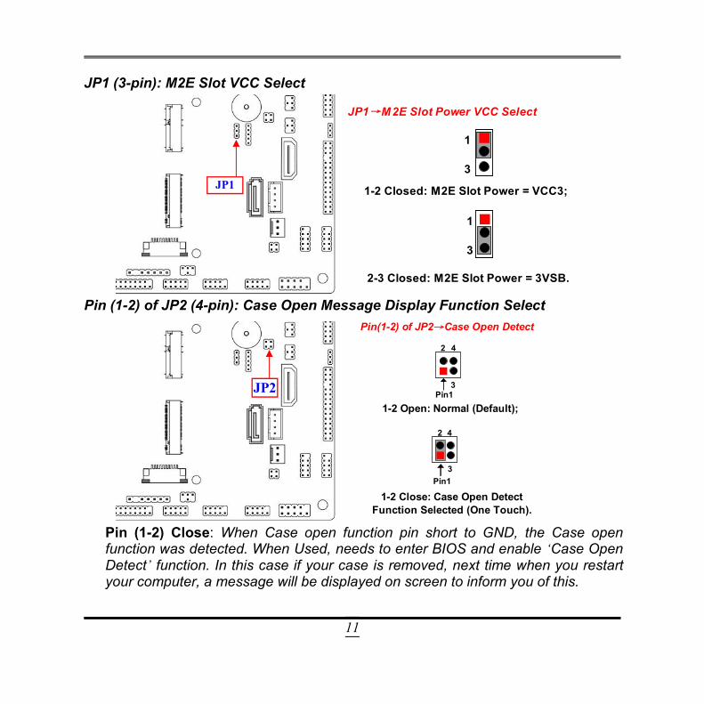
JP1 (3-pin): M2E Slot VCC Select
2-3 Closed: M2E Slot Power = 3VSB.
JP1→M2E Slot Power VCC Select
1-2 Closed: M2E Slot Power = VCC3;
1
3
1
3
Pin (1-2) of JP2 (4-pin): Case Open Message Display Function Select
2
Pin1
2
Pin1
4
3
3
4
Pin(1-2) of JP2→Case Open Detect
1-2 Open: Normal (Default);
1-2 Close: Case Open Detect Function Selected (One Touch).
Pin (1-2) Close: When Case open function pin short to GND, the Case openfunction was detected. When Used, needs to enter BIOS and enable ‘Case OpenDetect’ function. In this case if your case is removed, next time when you restartyour computer, a message will be displayed on screen to inform you of this.
JP1
JP2
12
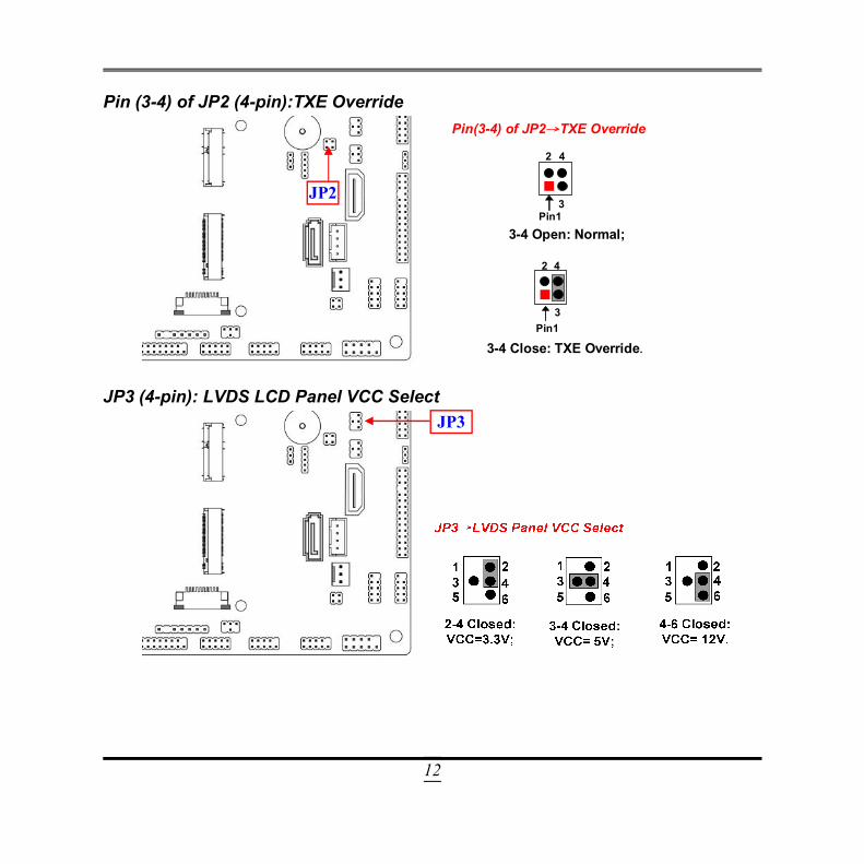
Pin (3-4) of JP2 (4-pin):TXE Override
2
Pin1
2
Pin1
4
3
3
4
Pin(3-4) of JP2→TXE Override
3-4 Open: Normal;
3-4 Close: TXE Override.
JP3 (4-pin): LVDS LCD Panel VCC SelectJP3
JP2
13
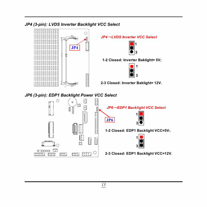
JP4 (3-pin): LVDS Inverter Backlight VCC Select
2-3 Closed: Inverter Baklight= 12V.
JP4→LVDS Inverter VCC Select
1-2 Closed: Inverter Baklight= 5V;
1
3
1
3
JP6 (3-pin): EDP1 Backlight Power VCC Select
2-3 Closed: EDP1 Backlight VCC=12V.
JP6→EDP1 Backlight VCC Select
1-2 Closed: EDP1 Backlight VCC=5V;
3
1
3
1
JP4
JP6
14
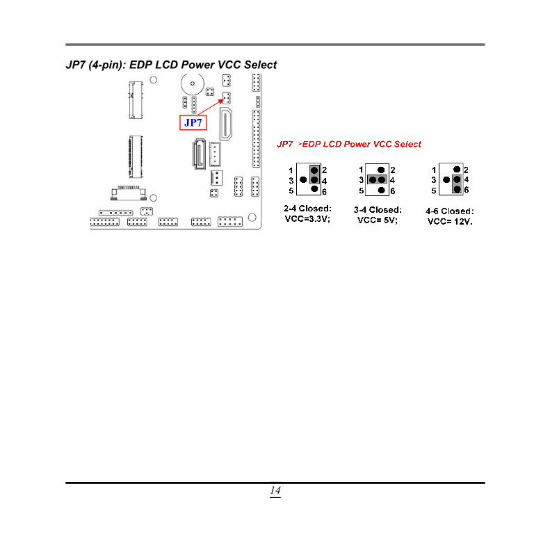
JP7 (4-pin): EDP LCD Power VCC Select
JP7
15
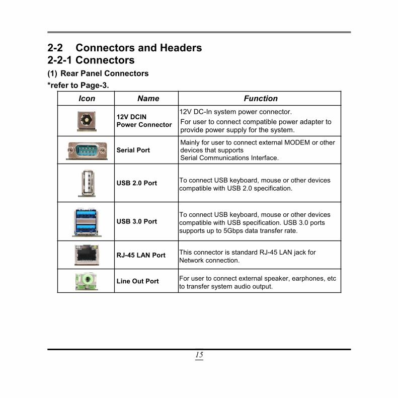
2-2 Connectors and Headers2-2-1 Connectors(1) Rear Panel Connectors*refer to Page-3.
Icon Name Function
12V DCINPower Connector
12V DC-In system power connector.For user to connect compatible power adapter toprovide power supply for the system.
Serial PortMainly for user to connect external MODEM or otherdevices that supportsSerial Communications Interface.
USB 2.0 Port To connect USB keyboard, mouse or other devicescompatible with USB 2.0 specification.
USB 3.0 PortTo connect USB keyboard, mouse or other devicescompatible with USB specification. USB 3.0 portssupports up to 5Gbps data transfer rate.
RJ-45 LAN Port This connector is standard RJ-45 LAN jack forNetwork connection.
Line Out Port For user to connect external speaker, earphones, etcto transfer system audio output.
16
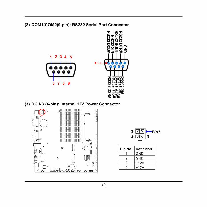
(2) COM1/COM2(9-pin): RS232 Serial Port Connector
1 2 3 4 5
6 7 8 9
RS232 DCD# RS232 SIN
RS232 SOUT RS232 DTR#
GND RS232 RI# RS232 CTS# RS232 RTS# RS232 DSR#
Pin1
(3) DCIN3 (4-pin): Internal 12V Power Connector
Pin No. Definition 1 GND 2 GND 3 +12V 4 +12V
Pin1
2 3
4
17
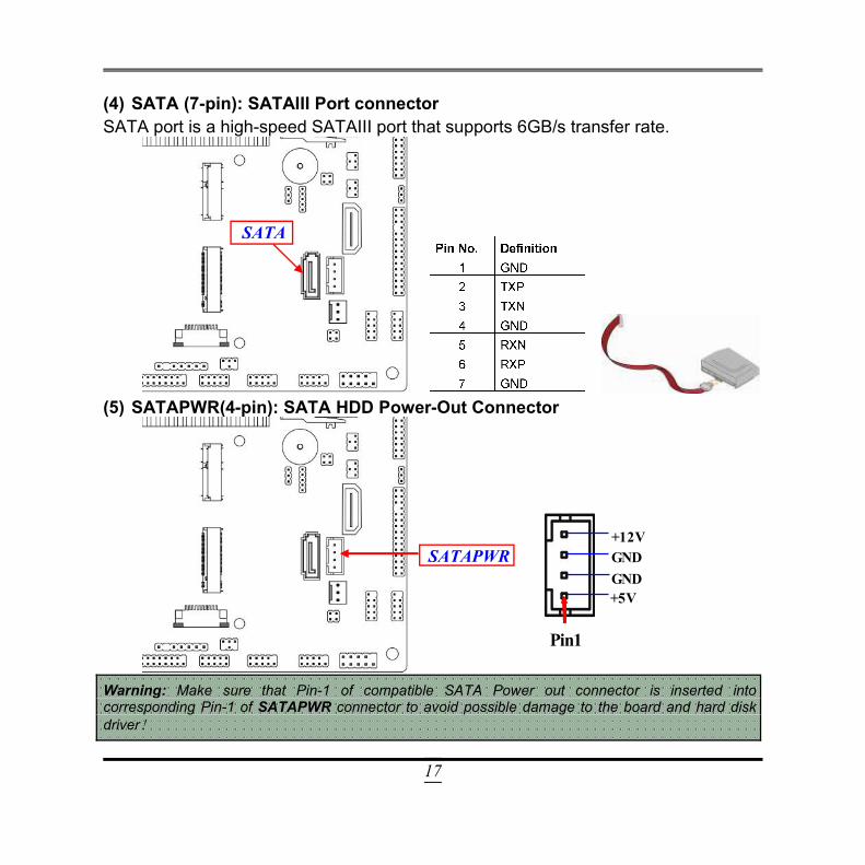
(4) SATA (7-pin): SATAIII Port connectorSATA port is a high-speed SATAIII port that supports 6GB/s transfer rate.
(5) SATAPWR(4-pin): SATA HDD Power-Out Connector
Pin1
+5V GND
GND +12V
Warning: Make sure that Pin-1 of compatible SATA Power out connector is inserted intocorresponding Pin-1 of SATAPWR connector to avoid possible damage to the board and hard diskdriver!
SATA
SATAPWR
18
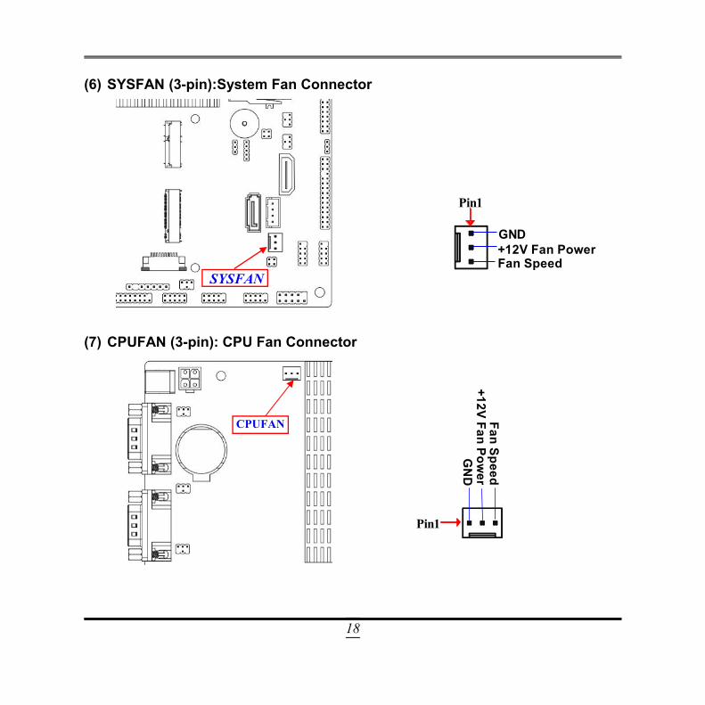
(6) SYSFAN (3-pin):System Fan Connector
Fan Speed
GND
Pin1
+12V Fan Power
(7) CPUFAN (3-pin): CPU Fan Connector
Fan Speed
GN
D
Pin1
+12V Fan Power
SYSFAN
CPUFAN
19
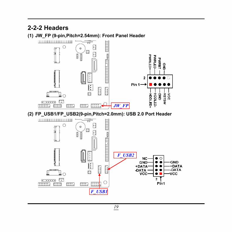
2-2-2 Headers(1) JW_FP (9-pin,Pitch=2.54mm): Front Panel Header
(2) FP_USB1/FP_USB2(9-pin,Pitch=2.0mm): USB 2.0 Port Header
F_USB1
F_USB2
JW_FP
20
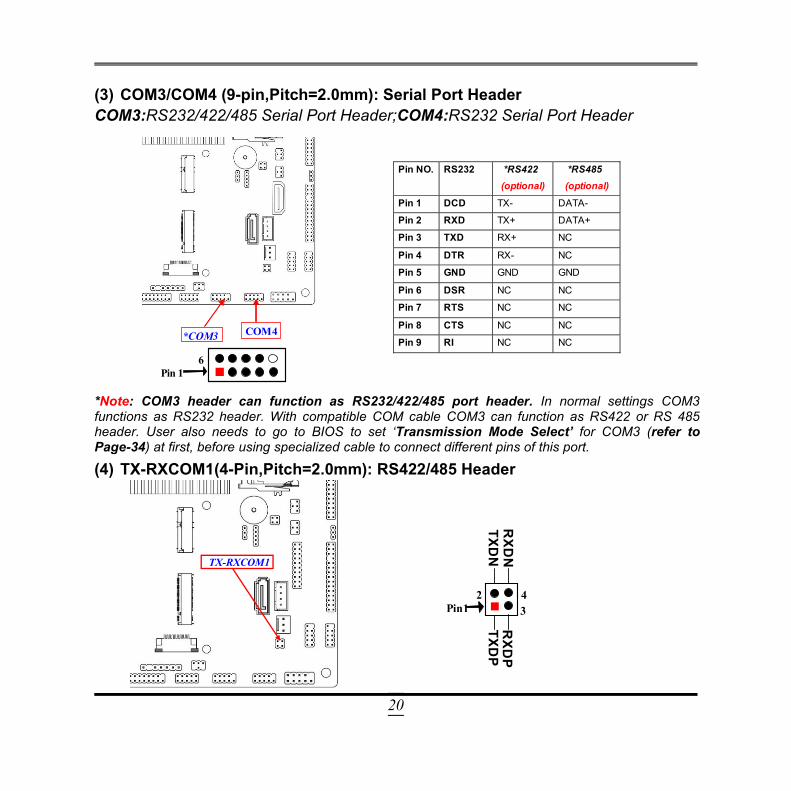
(3) COM3/COM4 (9-pin,Pitch=2.0mm): Serial Port HeaderCOM3:RS232/422/485 Serial Port Header;COM4:RS232 Serial Port Header
6 Pin 1
COM4 *COM3
Pin NO. RS232 *RS422
(optional)
*RS485 (optional)
Pin 1 DCD TX- DATA-
Pin 2 RXD TX+ DATA+
Pin 3 TXD RX+ NC
Pin 4 DTR RX- NC
Pin 5 GND GND GND
Pin 6 DSR NC NC
Pin 7 RTS NC NC
Pin 8 CTS NC NC
Pin 9 RI NC NC
*Note: COM3 header can function as RS232/422/485 port header. In normal settings COM3functions as RS232 header. With compatible COM cable COM3 can function as RS422 or RS 485header. User also needs to go to BIOS to set ‘Transmission Mode Select’ for COM3 (refer toPage-34) at first, before using specialized cable to connect different pins of this port.
(4) TX-RXCOM1(4-Pin,Pitch=2.0mm): RS422/485 Header
Pin1 2
3 4
TXDP
RXD
P TXD
N
RXD
N TX-RXCOM1
21
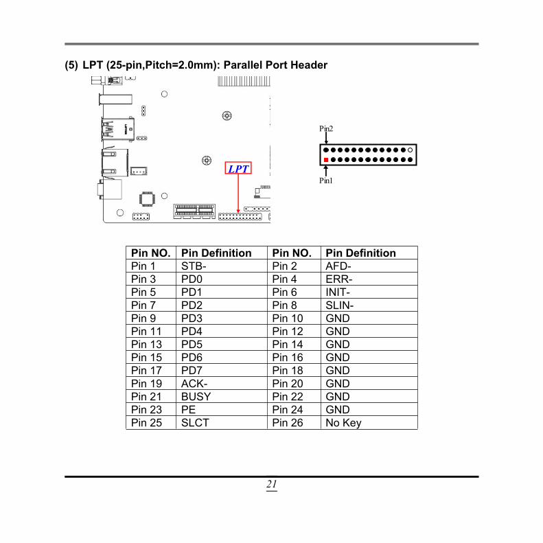
(5) LPT (25-pin,Pitch=2.0mm): Parallel Port Header
Pin1
Pin2
Pin NO. Pin Definition Pin NO. Pin DefinitionPin 1 STB- Pin 2 AFD-Pin 3 PD0 Pin 4 ERR-Pin 5 PD1 Pin 6 INIT-Pin 7 PD2 Pin 8 SLIN-Pin 9 PD3 Pin 10 GNDPin 11 PD4 Pin 12 GNDPin 13 PD5 Pin 14 GNDPin 15 PD6 Pin 16 GNDPin 17 PD7 Pin 18 GNDPin 19 ACK- Pin 20 GNDPin 21 BUSY Pin 22 GNDPin 23 PE Pin 24 GNDPin 25 SLCT Pin 26 No Key
LPT
22
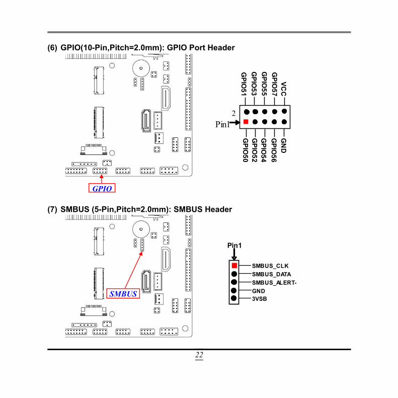
(6) GPIO(10-Pin,Pitch=2.0mm): GPIO Port Header
VC
C
Pin1 2
GPIO
57 G
PIO55
GPIO
53
GN
D
GPIO
56 G
PIO54
GPIO
52 G
PIO50
GPIO
51
(7) SMBUS (5-Pin,Pitch=2.0mm): SMBUS Header
Pin1
GND
SMBUS_DATA SMBUS_CLK
3VSB
SMBUS_ALERT-
SMBUS_DATA
SMBUS
GPIO
23
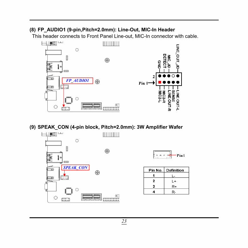
(8) FP_AUDIO1 (9-pin,Pitch=2.0mm): Line-Out, MIC-In HeaderThis header connects to Front Panel Line-out, MIC-In connector with cable.
(9) SPEAK_CON (4-pin block, Pitch=2.0mm): 3W Amplifier Wafer
FP_AUDIO1
SPEAK_CON
24
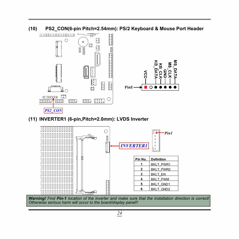
(10) PS2_CON(6-pin Pitch=2.54mm): PS/2 Keyboard & Mouse Port Header
(11) INVERTER1 (6-pin,Pitch=2.0mm): LVDS Inverter
Pin No. Definition 1 BKLT_PWR1 2 BKLT_PWR2 3 BKLT_EN 4 BKLT_PWM 5 BKLT_GND1 6 BKLT_GND2
Pin1
Warning! Find Pin-1 location of the inverter and make sure that the installation direction is correct!Otherwise serious harm will occur to the board/display panel!!
PS2_CON
INVERTER1
25
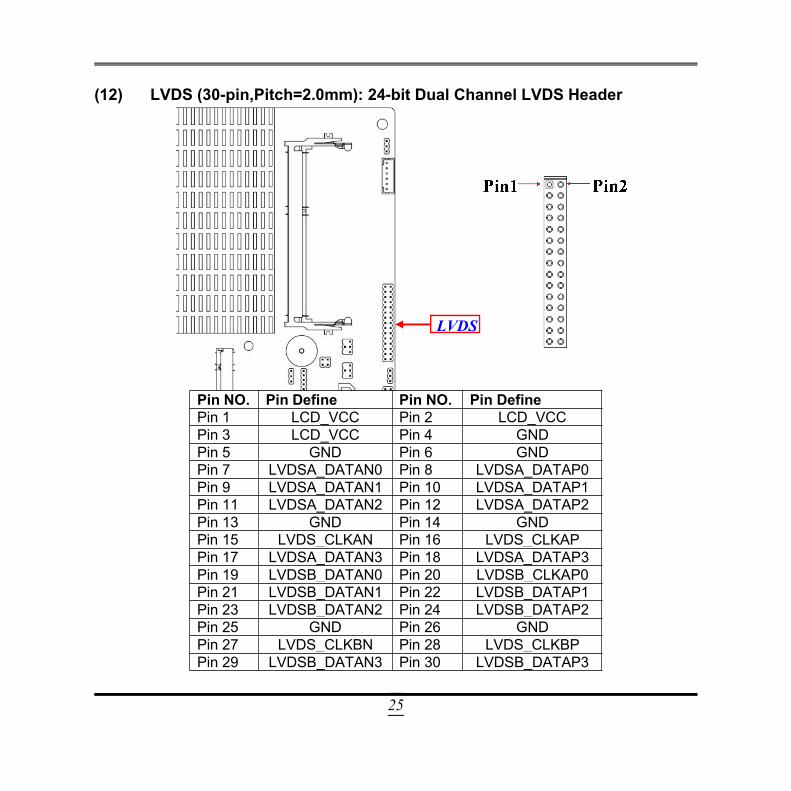
(12) LVDS (30-pin,Pitch=2.0mm): 24-bit Dual Channel LVDS Header
Pin NO. Pin Define Pin NO. Pin DefinePin 1 LCD_VCC Pin 2 LCD_VCCPin 3 LCD_VCC Pin 4 GNDPin 5 GND Pin 6 GNDPin 7 LVDSA_DATAN0 Pin 8 LVDSA_DATAP0Pin 9 LVDSA_DATAN1 Pin 10 LVDSA_DATAP1Pin 11 LVDSA_DATAN2 Pin 12 LVDSA_DATAP2Pin 13 GND Pin 14 GNDPin 15 LVDS_CLKAN Pin 16 LVDS_CLKAPPin 17 LVDSA_DATAN3 Pin 18 LVDSA_DATAP3Pin 19 LVDSB_DATAN0 Pin 20 LVDSB_CLKAP0Pin 21 LVDSB_DATAN1 Pin 22 LVDSB_DATAP1Pin 23 LVDSB_DATAN2 Pin 24 LVDSB_DATAP2Pin 25 GND Pin 26 GNDPin 27 LVDS_CLKBN Pin 28 LVDS_CLKBPPin 29 LVDSB_DATAN3 Pin 30 LVDSB_DATAP3
LVDS
26
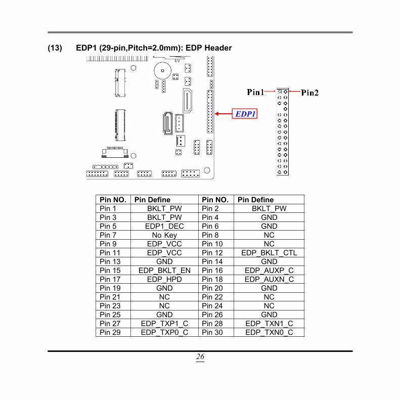
(13) EDP1 (29-pin,Pitch=2.0mm): EDP Header
Pin NO. Pin Define Pin NO. Pin DefinePin 1 BKLT_PW Pin 2 BKLT_PWPin 3 BKLT_PW Pin 4 GNDPin 5 EDP1_DEC Pin 6 GNDPin 7 No Key Pin 8 NCPin 9 EDP_VCC Pin 10 NCPin 11 EDP_VCC Pin 12 EDP_BKLT_CTLPin 13 GND Pin 14 GNDPin 15 EDP_BKLT_EN Pin 16 EDP_AUXP_CPin 17 EDP_HPD Pin 18 EDP_AUXN_CPin 19 GND Pin 20 GNDPin 21 NC Pin 22 NCPin 23 NC Pin 24 NCPin 25 GND Pin 26 GNDPin 27 EDP_TXP1_C Pin 28 EDP_TXN1_CPin 29 EDP_TXP0_C Pin 30 EDP_TXN0_C
EDP1

27
Chapter 3Introducing BIOS
Notice! The BIOS options in this manual are for reference only. Differentconfigurations may lead to difference in BIOS screen and BIOSscreens in manuals are usually the first BIOS version when the board isreleased and may be different from your purchased motherboard.Users are welcome to download the latest BIOS version form ourofficial website.
The BIOS is a program located on a Flash Memory on the motherboard. This programis a bridge between motherboard and operating system. When you start the computer,the BIOS program will gain control. The BIOS first operates an auto-diagnostic testcalled POST (power on self test) for all the necessary hardware, it detects the entirehardware device and configures the parameters of the hardware synchronization.Only when these tasks are completed done it gives up control of the computer tooperating system (OS). Since the BIOS is the only channel for hardware and softwareto communicate, it is the key factor for system stability, and in ensuring that yoursystem performance as its best.
3-1 Entering SetupPower on the computer and by pressing <Del> immediately allows you to enter Setup.If the message disappears before your respond and you still wish to enter Setup,restart the system to try again by turning it OFF then ON or pressing the “RESET”button on the system case. You may also restart by simultaneously pressing <Ctrl>,<Alt> and <Delete> keys. If you do not press the keys at the correct time and thesystem does not boot, an error message will be displayed and you will again be askedto
Press <Del> to enter Setup; press < F7> to enter pop-up Boot menu.
28
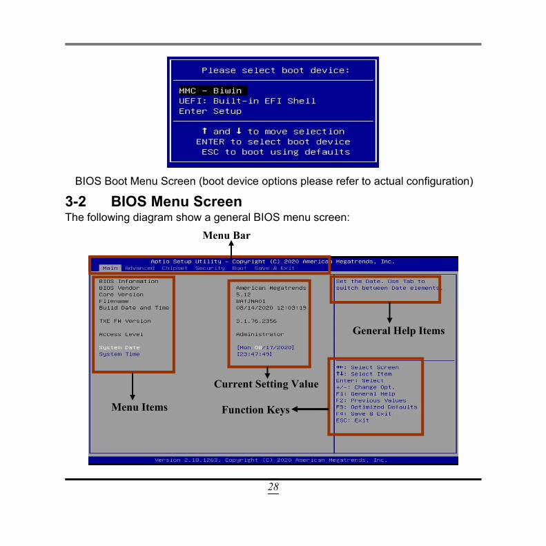
BIOS Boot Menu Screen (boot device options please refer to actual configuration)
3-2 BIOS Menu ScreenThe following diagram show a general BIOS menu screen:
Menu Bar
Menu Items
Current Setting Value
Function Keys
General Help Items
29
3-3 Function KeysIn the above BIOS Setup main menu of, you can see several options. We will explainthese options step by step in the following pages of this chapter, but let us first see ashort description of the function keys you may use here: Press (left, right) to select screen; Press (up, down) to choose, in the main menu, the option you want to confirm
or to modify. Press <Enter> to select. Press <+>/<–> keys when you want to modify the BIOS parameters for the active
option. [F1]: General help. [F2]: Previous value. [F3]: Optimized defaults. [F4]: Save & Exit. Press <ESC> to quit the BIOS Setup.
3-4 Getting HelpMain MenuThe on-line description of the highlighted setup function is displayed at the top rightcorner the screen.
Status Page Setup Menu/Option Page Setup MenuPress [F1] to pop up a small help window that describes the appropriate keys to useand the possible selections for the highlighted item. To exit the Help Window, press<Esc>.
30
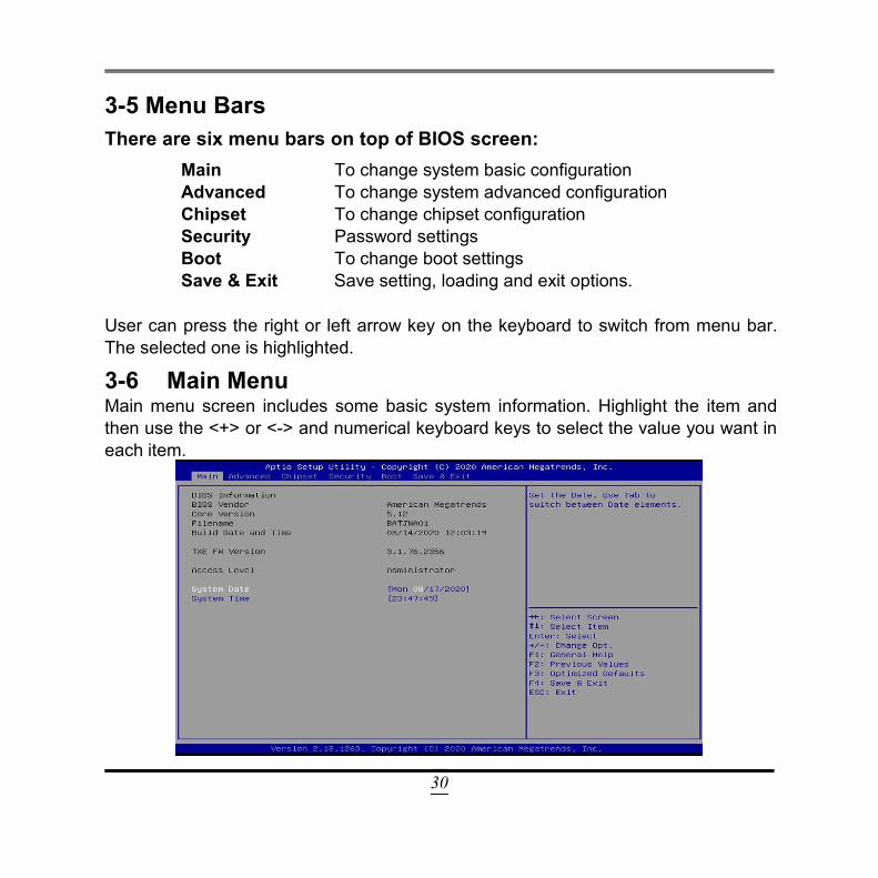
3-5 Menu BarsThere are six menu bars on top of BIOS screen:
Main To change system basic configurationAdvanced To change system advanced configurationChipset To change chipset configurationSecurity Password settingsBoot To change boot settingsSave & Exit Save setting, loading and exit options.
User can press the right or left arrow key on the keyboard to switch from menu bar.The selected one is highlighted.
3-6 Main MenuMain menu screen includes some basic system information. Highlight the item andthen use the <+> or <-> and numerical keyboard keys to select the value you want ineach item.
31
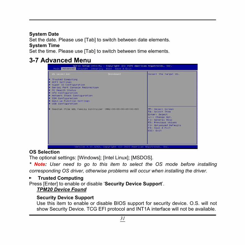
System DateSet the date. Please use [Tab] to switch between date elements.System TimeSet the time. Please use [Tab] to switch between time elements.
3-7 Advanced Menu
OS SelectionThe optional settings: [Windows]; [Intel Linux]; [MSDOS].* Note: User need to go to this item to select the OS mode before installingcorresponding OS driver, otherwise problems will occur when installing the driver.► Trusted ComputingPress [Enter] to enable or disable ‘Security Device Support’.
TPM20 Device FoundSecurity Device SupportUse this item to enable or disable BIOS support for security device. O.S. will notshow Security Device. TCG EFI protocol and INT1A interface will not be available.
32
The optional settings: [Disabled]; [Enabled].When set as [Enabled], user can make further settings in the following items:SHA-1 PCR BankUse this item to enable or disable SHA-1 PCR Bank.The optional settings: [Disabled]; [Enabled].SHA256 PCR BankUse this item to enable or disable SHA256 PCR Bank.The optional settings: [Disabled]; [Enabled].
► ACPI SettingsPress [Enter] to make settings for the following sub-items:ACPI SettingsACPI Sleep StateUse this item to select the highest ACPI sleep state the system will enter when theSUSPEND button is pressed.The optional settings: [Suspend Disabled]; [S3 (Suspend to RAM)].
► Super I/O ConfigurationPress [Enter] to make settings for the following sub-items:Super IO Configuration► Serial Port 1 ConfigurationUse this item to set parameters of Serial Port 1 (COMA).Press [Enter] to make settings for the following items:Serial PortThe optional settings: [Disabled]; [Enabled].When set as [Enabled], user can make further settings in the following items:Device Settings
Change SettingsUse this item to select an optimal setting for Super IO Device.The optional settings: [Auto]; [IO=3F8h; IRQ=4;]; [IO=2F8h; IRQ=3;]; [IO=3E8h;IRQ=4;]; [IO=2E8h; IRQ=3;].► Serial Port 2 Configuration
33
Press [Enter] to make settings for the following sub-items:When set as [Enabled], user can make further settings in the following items:Device Settings
Serial PortUse this item to enable or disable Serial Port 2 (COMB).The optional settings: [Disabled]; [Enabled].When set as [Enabled], user can make further settings in the following items:Change SettingsUse this item to select an optimal setting for Super IO Device.The optional settings: [Auto]; [IO=3F8h; IRQ=4;]; [IO=2F8h; IRQ=3;]; [IO=3E8h;IRQ=4;]; [IO=2E8h; IRQ=3;].► Serial Port 3 ConfigurationPress [Enter] to make settings for the following sub-items:
Serial PortUse this item to enable or disable Serial Port 3 (COMC).The optional settings: [Disabled]; [Enabled].When set as [Enabled], user can make further settings in the following items:Device Settings
Change SettingsUse this item to select an optimal setting for Super IO Device.The optional settings: [Auto]; [IO=3F8h; IRQ=10;]; [IO=2F8h; IRQ=10;]; [IO=3E8h;IRQ=10;]; [IO=2E8h; IRQ=10;]; [IO=2F0h; IRQ=10;]; [IO=2E0h; IRQ=10;].Transmission Mode SelectThe optional settings: [RS422]; [RS232]; [RS485].► Serial Port 4 ConfigurationPress [Enter] to make settings for the following sub-items:When set as [Enabled], user can make further settings in the following items:Device Settings
Serial Port
34
Use this item to enable or disable Serial Port 4 (COMD).The optional settings: [Disabled]; [Enabled].When set as [Enabled], user can make further settings in the following items:Device Settings
Change SettingsUse this item to select an optimal setting for Super IO Device.The optional settings: [Auto]; [IO=3F8h; IRQ=10;]; [IO=2F8h; IRQ=10;]; [IO=3E8h;IRQ=10;]; [IO=2E8h; IRQ=10;]; [IO=2F0h; IRQ=10;]; [IO=2E0h; IRQ=10;].
Parallel Port ConfigurationPress [Enter] to make settings for the following items:Parallel Port ConfigurationParallel PortUse this item to enable or disable Parallel Port (LPT/LPTE).The optional settings: [Disabled]; [Enabled].When set as [Enabled], user can make further settings in the following items:Device Settings
Change SettingsUse this item to select an optimal setting for Super IO Device.The optional settings: [Auto]; [IO=378h; IRQ=5;]; [IO=378h;IRQ=5,6,7,9,10,11,12;]; [IO=278h; IRQ=5,6,7,9,10,11,12;]; [IO=3BCh;IRQ=5,6,7,9,10,11,12;].Device ModeUse this item to change the Printer Port mode.The optional settings: [STD Printer Mode]; [SPP Mode]; [EPP-1.9 and SPP Mode];[EPP-1.7 and SPP Mode]; [ECP Mode]; [ECP and EPP 1.9 Mode]; [ECP and EPP1.7 Mode].
ERP SupportThis item is Energy-Related Products function.
35
The optional settings: [Disabled]; [Enabled].This item should be set as [Disabled] if you wish to have all active wake-upfunctions.Case Open DetectUse this item to detect if case have ever been opened. Show message in POST.The optional settings: [Disabled]; [Enabled].When set as [Enabled], system will detect if COPEN has been short or not (refer toJP2 jumper setting for Case Open Detection); if Pin 1&2 of JP2 is short, systemwill show Case Open Message during POST.
WatchDog Reset TimerUse this item to enable or disable WDT reset function.The optional settings: [Disabled]; [Enabled].When set as [Enabled], the following sub-items shall appear:WatchDog Reset Timer ValueUser can select a value in the range of [4] to [255] seconds when ‘WatchDogReset Timer Unit’ set as [Sec]; or in the range of [1] to [255] minutes when‘WatchDog Reset Timer Unit’ set as [Min].WatchDog Reset Timer UnitThe optional settings: [Sec.]; [Min.].WatchDog Wake-up TimerThis item support WDT wake-up.The optional settings: [Disabled]; [Enabled].When set as [Enabled], the following sub-items shall appear:WatchDog Wake-up Timer ValueUser can select a value in the range of [10] to [4095] seconds when ‘WatchDogWake-up Timer Unit’ set as [Sec]; or in the range of [1] to [4095] minutes when‘WatchDog Wake-up Timer Unit’ set as [Min].WatchDog Wake-up Timer UnitThe optional settings: [Sec.]; [Min.].

36
ATX Power Emulate AT PowerThis item support Emulate AT power function, MB power On/Off control by powersupply. Use needs to select ‘AT or ATX Mode’ on MB jumper at first (refer toJAT_ATX1 jumper setting for ATX Mode & AT Mode Select).
Serial Port Console RedirectionCOM1Console RedirectionUse this item to enable or disable Console Redirection.The optional settings: [Disabled]; [Enabled].When set as [Enabled], user can make further settings in the following items: Console Redirection SettingsThe settings specify how the host computer and the remote computer (which theuser is using) will exchange data. Both computers should have the same orcompatible settings.Press [Enter] to make settings for the following sub-items.
COM1Console Redirection Settings
Terminal TypeThe optional settings: [VT100]; [VT100+]; [VT-UTF8]; [ANSI].Emulation: [ANSI]: Extended ASCII char set; [VT100]: ASCII char set;[VT100+]: Extends VT100 to support color, function keys, etc.; [VT-UTF8]:Uses UTF8 encoding to map Unicode chars onto 1 or more bytes.Bits per secondUse this item to select serial port transmission speed. The speed must bematched on the other side. Long or noisy lines may require lower speeds.The optional settings: [9600]; [19200]; [38400]; [57600]; [115200].Data BitsThe optional settings: [7]; [8].ParityA parity bit can be sent with the data bits to detect some transmission errors.The optional settings: [None]; [Even]; [Odd]; [Mark]; [Space].
37
[Even]: parity bit is 0 if the num of 1’s in the data bits is even;[Odd]: parity bit is 0 if num of 1’s in the data bits is odd;[Mark]: parity bit is always 1;[Space]: parity bit is always 0;[Mark] and [Space]: parity do not allow for error detection.Stop BitsStop bits indicate the end of a serial data packet. (A start bit indicates thebeginning). The standard setting is 1 stop bit. Communication with slowdevices may require more than 1 stop bit.The optional settings: [1]; [2].Flow ControlFlow control can prevent data loss from buffer overflow. When sending data, ifthe receiving buffers are full, a “stop” signal can be sent to stop the data flow.Once the buffers are empty, a “start” signal can be sent to re-start the flow.Hardware flow control uses two wires to send start/stop signals.The optional settings: [None]; [Hardware RTS/CTS].VT-UTF8 Combo Key SupportUse this item to enable VT-UTF8 Combination Key Support for ANSI/VT100terminals.The optional settings: [Disabled]; [Enabled].Recorder ModeWith this mode enable only text will be sent. This is to capture Terminal data.The optional settings: [Disabled]; [Enabled].Resolution 100x31Use this item to enable or disable extended terminal resolution.The optional settings: [Disabled]; [Enabled].Legacy OS Redirection ResolutionOn Legacy OS, the Number of Rows and Columns supported redirection.The optional settings: [80x24]; [80x25].Putty KeypadUse this item to select FunctionKey and KeyPad on Putty.The optional settings: [VT100]; [Intel Linux]; [XTERMR6]; [SCO]; [ESCN];[VT400].
38
Redirect After BIOS POSTThe optional settings: [Always Enable]; [BootLoader].When [Bootloader] is selected, then Legacy Console Redirection is disabledbefore booting to legacy OS. When [Always Enabled] is selected, then LegacyConsole Redirection is enabled for legacy OS. Default setting for this option isset to [Always Enabled].
Serial Port for Out-of-Band Management/Windows Emergency Management Services (EMS)Console RedirectionThe optional settings: [Disabled]; [Enabled].When set as [Enabled], the following sub-items shall appear: Console Redirection SettingsThe settings specify how the host computer and the remote computer (which theuser is using) will exchange data. Both computers should have the same orcompatible settings.Press [Enter] to make settings for the following items:Out-of-Band Mgmt PortThe default setting is: [COM1].Terminal TypeThe optional settings: [VT100]; [VT100+]; [VT-UTF8]; [ANSI].[VT-UTF8] is the preferred terminal type for out-of-band management. The nextbest choice is [VT100+] and them [VT100]. See above, in Console RedirectionSettings page, for more help with Terminal Type/Emulation.Bits per secondUse this item to select serial port transmission speed. The speed must bematched on the other side. Long or noisy lines may require lower speeds.The optional settings: [9600]; [19200]; [57600]; [115200].Flow ControlFlow control can prevent data loss from buffer overflow. When sending data, ifthe receiving buffers are full, a “stop” signal can be sent to stop the data flow.Once the buffers are empty, a “start” signal can be sent to re-start the flow.
39
Hardware flow control uses two wires to send start/stop signals.The optional settings: [None]; [Hardware RTS/CTS]; [Software Xon/Xoff].Data BitsThe default setting is: [8].*This item may or may not show up, depending on different configuration.ParityThe default setting is: [None].*This item may or may not show up, depending on different configuration.Stop BitsThe default setting is: [1].*This item may or may not show up, depending on different configuration.
► PC Health StatusPress [Enter] to view current hardware health status.
► CPU ConfigurationPress [Enter] to view current CPU configuration and make settings for the followingsub-items:EISTUse this item to enable or disable Intel SpeedStep.The optional settings: [Disabled]; [Enabled].When set as [Enabled], the following sub-items shall appear:Turbo ModeUse this item to enable or disable Turbo Mode (requires Intel Speed Step or IntelSpeed Shift to be available and enabled.)The optional settings: [Disabled]; [Enabled].*Note: This item might not be available depending on configuration.C-StatesUse this item to enable or disable C-State.The optional settings: [Disabled]; [Enabled].When set as [Enabled], user can make further settings in the following sub-items:
Enhanced C-statesThe optional settings: [Disabled]; [Enabled].This option is for user to enable or disable C1E. When set as [Enabled], CPU
40
will switch to minimum speed when all cores enter C-State.Max Package C StateThis item is for user to control the Max Package C State that the processor willsupport.The optional items are: [PC2]; [PC1]; [C0].Max Core C StatesThis option controls the Max Core C State that cores will support.The optional items are: [Fused Value];[Core C10] ;[Core C9] ;[Core C8] ;[Core C7];[Core C6];[Core C1];[Unlimited].
Network Stack ConfigurationPress [Enter] to go to ‘Network Stack’ screen to make further settings.Network StackThe optional settings are: [Disabled]; [Enabled].When set as [Enabled], the following sub-items shall appear:Ipv4 PXE SupportUse this item to enable Ipv4 PXE Boot Support. When set as [Disabled], Ipv4 bootoptional will not be created.The optional settings: [Disabled]; [Enabled].Ipv6 PXE SupportUse this item to enable Ipv6 PXE Boot Support. When set as [Disabled], Ipv6 bootoptional will not be created.The optional settings: [Disabled]; [Enabled].PXE Boot Wait TimeUse this item to set wait time to press [ESC] key to abort the PXE boot.Media Detect CountUse this item to set number of times presence of media will be checked.The optional settings range from [1] to [50].
CSM ConfigurationPress [Enter] to make settings for the following sub-items:Compatibility Support Module Configuraton
Boot option filter
41
This item controls Legacy/UEFI ROMs priority.The optional settings: [UEFI and Legacy]; [Legacy Only]; [UEFI Only].NetworkThis item controls the execution of UEFI and Legacy PXE OpROM.The optional settings: [Do not Launch]; [UEFI]; [Legacy].StorageThis item controls the execution of UEFI and Legacy Storage OpROM.The optional settings: [Do not Launch]; [UEFI]; [Legacy].VideoThis item controls the execution of UEFI and Legacy Video OpROM.The optional settings: [UEFI]; [Legacy].Other PCI devicesThis item determines OpROM execution policy for devices other than Network,Storage or Video.The optional settings: [Do not Launch]; [UEFI]; [Legacy].
► Wake-up Function SettingsPress [Enter] to make settings for the following sub-items:Wake-up System with Fixed TimeUse this item to enable or disable system wake-up by RTC alarm.The optional settings: [Disabled]; [Enabled].When set as [Enabled], the following items shall appear:Wake-up HourUse this item to select 0-23. For example enter 3 for 3am and 15 for 3pm.Wake-up MinuteUse this item to select 0-59.Wake-up SecondUse this item to select 0-59.
Wake-up System with Dynamic TimeUse this item to enable or disable System wake on alarm event.System will wake on the current time + Increase minute(s).The optional settings: [Disabled]; [Enabled].When set as [Enabled], system will wake on the current time + increased
42
minute(s).
USB Wake-up from S4Use this item to enable or disable USB S4 Wake-up.The optional settings: [Enabled]; [Disabled].*Note: This function is supported when ‘ERP Support’ is set as [Disabled].
USB ConfigurationPress [Enter] to make settings for the following sub-items:USB ConfigurationUSB Devices
Legacy USB SupportThe optional settings: [Enabled]; [Disabled]; [Auto].[Enabled]: To enable legacy USB support.[Disabled]: To keep USB devices available only for EFI specification,[Auto]: To disable legacy support if no USB devices are connected.XHCI Hand-offThis is a workaround for OSes without XHCI hand-off support. The XHCIownership change should be claimed by XHCI driver.The optional settings: [Enabled]; [Disabled].USB Mass Storage Driver SupportUse this item to enable or disable USB mass storage driver support.The optional settings: [Disabled]; [Enabled].
USB Hardware Delays and Time-outs:USB Transfer Time-outUse this item to set the time-out value for control, bulk, and interrupt transfers.The optional settings: [1 sec]; [5 sec]; [10 sec]; [20 sec].Device Reset Time-outUse this item to set USB mass storage device start unit command time-out.The optional settings: [10 sec]; [20 sec]; [30 sec]; [40 sec].Device Power-up DelayUse this item to set maximum time the device will take before it properly reports
43
itself to the Host Controller. ‘Auto’ uses default value: for a root port it is 100 ms,for a Hub port the delay is taken from Hub descriptor.The optional settings: [Auto]; [Manual].Select [Manual] you can set value for the following sub-item: ‘Device power-upDelay in Seconds’, the delay range in from 1 to 40 seconds, in one secondincrements.
Realtek PCIe GBE Family Controller (MAC: XX:XX:XX:XX:XX:XX)
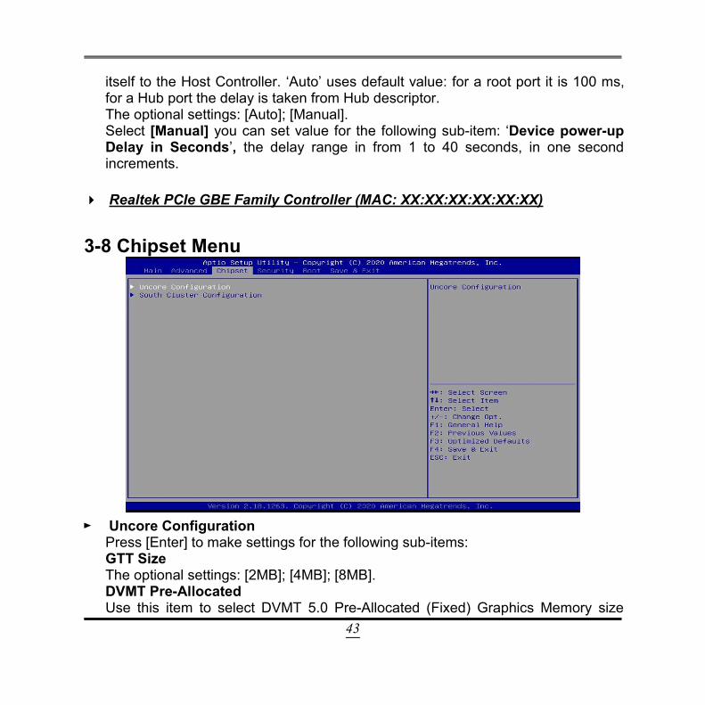
3-8 Chipset Menu
► Uncore ConfigurationPress [Enter] to make settings for the following sub-items:GTT SizeThe optional settings: [2MB]; [4MB]; [8MB].DVMT Pre-AllocatedUse this item to select DVMT 5.0 Pre-Allocated (Fixed) Graphics Memory size
44
used by the Internal Graphics Device.The optional settings: [64M]; [96M]; [128M]; [160M]; [192M]; [224M]; [256M];[288M]; [320M]; [352M]; [384M]; [416M]; [448M]; [480M]; [512M].DVMT Total Gfx MemUse this item to select DVMT 5.0 Total Graphics Memory size used by the InternalGraphics Device.The optional settings: [128M]; [256M]; [MAX].Active LFPUse this item to select the active configuration.The optional settings: [Disabled]; [Enabled].**Note: When set as [Enabled], user can make further settings in ‘LCD PanelType’, ‘LVDS FW Protect’, and ‘GMCH BLC Control’:LCD Panel TypeUse this item to select LCD panel used by Internal Graphics Device by selectingthe appropriate setup item.The optional settings: [800x600 1ch 24-bit]; [800x600 1ch 18-bit]; [1024x600 1ch18-bit]; [1024x768 1ch 24-bit]; [1024x768 1ch 18-bit]; [800x480 1ch 18-bit];[1366x768 1ch 18-bit]; [1440x900 2ch 18-bit]; [1366x768 1ch 24-bit]; [1440x9002ch 24-bit]; [1280x1024 2ch 24-bit]; [1280x800 1ch 18-bit] [1280x800 1ch 24-bit][1680x1050 2ch 24-bit]; [1920x768 1ch 24-bit]; [1920x1080 2ch 24-bit].LVDS FW ProtectUse this item to set LVDS FW Protect function.The optional settings: [Enabled]; [Disabled].GMCH BLC ControlUse this item for Back Light Control Settings.The optional settings: [PWM-Inverted]; [PWM-Normal].Primary IGFX Boot DisplayUse this item to select the Video Device which will be activated during POST. Thishas no effect if external graphics present. Secondary boot display selection willappear based on your selection. VGA mode will be supported only on primarydisplay.The optional settings: [Auto]; [HDMI]; [eDP]; [LVDS].
45
Secondary IGFX Boot DisplayUse this item to select Secondary Display Device.The optional settings: [Disabled]; [HDMI]; [eDP]; [LVDS].Memory InformationThe working memory information will be on display.
► South Cluster Configuration PCI Express ConfigurationPress [Enter] to make settings for the following sub-items:PCI Express Configuration
Peer Memory Write EnableThe optional settings: [Disabled]; [Enabled].Compliance ModeThe optional settings: [Disabled]; [Enabled]. SATA ConfigurationPress [Enter] to make settings for the following sub-items:SATA ControllerUse this item to enable or disable the Chipset SATA Controller. The ChipsetSATA controller supports the 2 black internal SATA ports (up to 3Gb/ssupported per port).The optional settings: [Enabled]; [Disabled].When set as [Enabled], the following items shall appear:SATA Mode SelectionUse this item to determine how SATA controller(s) operate.The default setting is: [AHCI].
SATA PortSATA PortUse this item to enable or disable each SATA port.The optional settings: [Disabled]; [Enabled].
46
M.2M.2Use this item to enable or disable SATA port.The optional settings: [Disabled]; [Enabled].
HD-Audio SupportUse this item to enable or disable HD-Audio Support.The optional settings: [Disabled]; [Enabled].SCC eMMC SupportUse this item to enable or disable SCC eMMC Support.The optional settings: [Disabled]; [Enabled].*Note: JNC8J-I3455D supports onboard eMMC.eMMC Max SpeedUse this item to select the eMMC max speed allowed.The optional settings: [HS400]; [HS200]; [DDR50].*Note: JNC8J-I3455D supports onboard eMMC.
System State after Power FailureUse this item to specify what state to go to when power re-applied after a powerfailure.The optional settings: [Always On]; [Always Off]; [Former State].
47
3-9 Security Menu
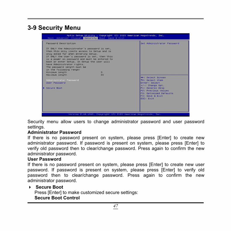
Security menu allow users to change administrator password and user passwordsettings.Administrator PasswordIf there is no password present on system, please press [Enter] to create newadministrator password. If password is present on system, please press [Enter] toverify old password then to clear/change password. Press again to confirm the newadministrator password.User PasswordIf there is no password present on system, please press [Enter] to create new userpassword. If password is present on system, please press [Enter] to verify oldpassword then to clear/change password. Press again to confirm the newadministrator password. Secure Boot
Press [Enter] to make customized secure settings:Secure Boot Control
48
The optional settings: [Disabled]; [Enabled].Secure Boot can be enabled if 1. System running in user mode with enrolledPlatform Key (PK); 2. CSM function is disabled.Secure Boot ModeThe optional settings: [Standard]; [Custom].Set UEFI Secure Boot Mode to Standard mode or Custom mode. This change iseffective after save. After reset, this mode will return to Standard mode.When set as [Custom], user can make further settings in the following items thatshow up: Key ManagementThis item enables experienced users to modify Secure Boot variables.Press [Enter] to make customized secure settings:Provision Factory Default KeysThis item is for user to install factory default secure boot keys when system is inSetup Mode.The optional settings: [Disabled]; [Enabled]. Enroll All Factory Default KeysThis item forces system to User Mode-install all Factory Default keys. Save all Secure Boot Variables
Secure Boot Variable/Size/Key#/Key Source Platform Key (PK)/Key Exchange Keys/Authorized Signatures/Forbidden
Signatures/ Authorized TimeStamps/OSRecovery SignaturesUse this item to enroll Factory Defaults or load the keys from a file with:1. Public Key Certificate in:a) EFI_SIGNATURE_LISTb) EFI_ CERT_X509 (DER encoded)c) EFI_ CERT_RSA2048 (bin)d) EFI_ CERT_SHA256 (bin)
2. Authenticated UEFI Variable
49
Key: Vendor, Custom, Mixed, Test (*) modified from Setup menu
3-10 Boot Menu
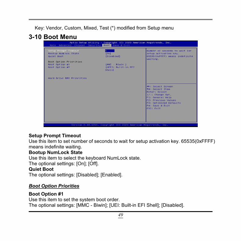
Setup Prompt TimeoutUse this item to set number of seconds to wait for setup activation key. 65535(0xFFFF)means indefinite waiting.Bootup NumLock StateUse this item to select the keyboard NumLock state.The optional settings: [On]; [Off].Quiet BootThe optional settings: [Disabled]; [Enabled].
Boot Option PrioritiesBoot Option #1Use this item to set the system boot order.The optional settings: [MMC - Biwin]; [UEI: Built-in EFI Shell]; [Disabled].
50
Boot Option #2Use this item to set the system boot order.The optional settings: [MMC - Biwin]; [UEI: Built-in EFI Shell]; [Disabled].
Hard Drive BBS PrioritiesUse this item to set the order of the legacy devices in this group.Press [Enter] to make customized secure settings:Boot Option#1The optional settings: [MMC - Biwin]; [Disabled].
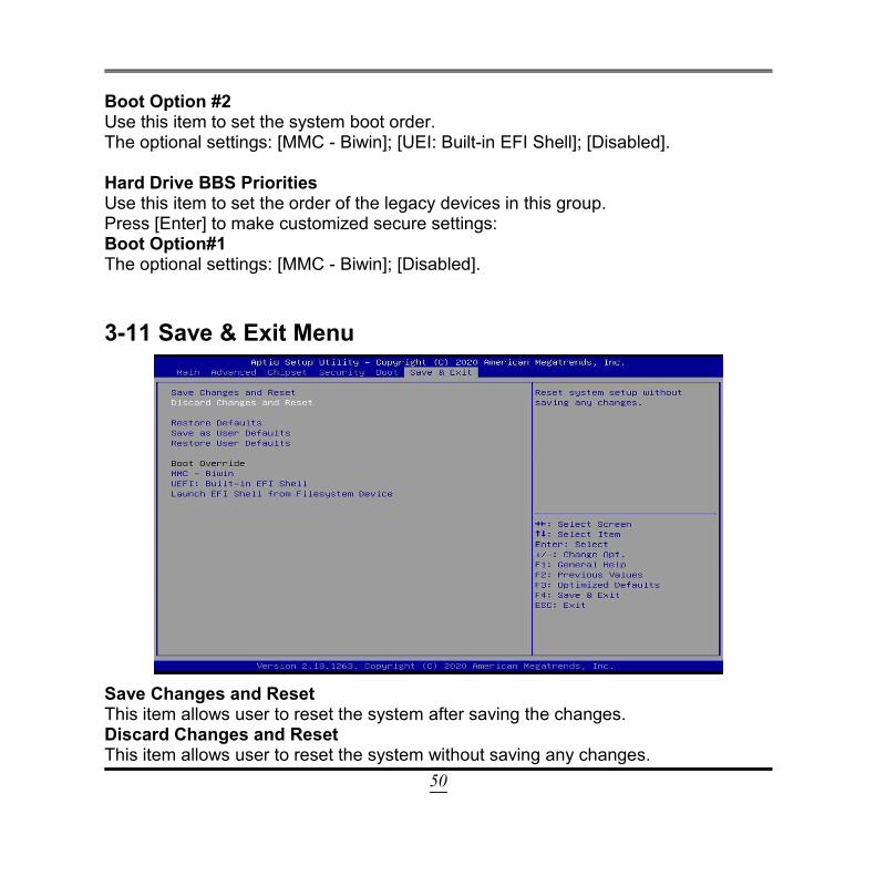
3-11 Save & Exit Menu
Save Changes and ResetThis item allows user to reset the system after saving the changes.Discard Changes and ResetThis item allows user to reset the system without saving any changes.
51
Restore DefaultsUse this item to restore /load default values for all the setup options.Save as User DefaultsUse this item to save the changes done so far as user defaults.Restore User DefaultsUse this item to restore defaults to all the setup options.
Boot OverrideThe available options here are dynamically updated and make system boot to anyboot option selected.MMC - BiwinUse this item to save or reset configuration of MMC – Biwin.UEFI: Built-in EFI ShellUse this item to save or reset configuration of UEFI.Lauch EFI Shell from Filesystem DeviceUse this item to launch EFI shell application (shell.efi) from one of the availablefilesystem device.