Embed Size (px)
Citation preview
Terraprobe Consulting Geotechnical & Environmental Engineering Construction Materials Inspection & Testing
Terraprobe Inc.Greater Toronto Hamilton – Niagara Central Ontario Northern Ontario 11 Indell Lane 903 Barton Street, Unit 22 220 Bayview Drive, Unit 25 1012 Kelly Lake Rd., Unit 1 Brampton, Ontario L6T 3Y3 Stoney Creek, Ontario L8E Barrie, Ontario L4N 4Y8 Sudbury, Ontario P3E 5P4 (905) 796-2650 Fax: 796-2250 (905) 643-7560 Fax: 643-7559 (705) 739-8355 Fax: 739-8369 (705) 670-0460 Fax: 670-0558
www.terraprobe.ca
GEOTECHNICAL INVESTIGATION PROPOSED ADDITION - VICTORIA PARK COMMUNITY HOMES
154 BRONTE STREET MILTON, ONTARIO
Prepared for: Victoria Park Community Homes 155 Queen Street North Hamilton, Ontario L8R 2V6
Attention: Ms. Lori-Anne Gagne
File No. 1-17-0214 September 25, 2017
© Terraprobe Inc.
Distribution:
3 Copies - Victoria Park Community Homes 1 Copy - Terraprobe Inc., Brampton
Victoria Park Community Homes September 25, 2017
154 Bronte Street, Milton, ON File No. 1-17-0214
Terraprobe Page i
TABLE OF CONTENTS
1. INTRODUCTION . . . . . . . . . . . . . . . . . . . . . . . . . . . . . . . . . . . . . . . . . . . . . . . . . . . . . . . . . . . . 1
2. SITE AND PROJECT DESCRIPTION . . . . . . . . . . . . . . . . . . . . . . . . . . . . . . . . . . . . . . . . . . . . 1
3. FIELD PROCEDURE . . . . . . . . . . . . . . . . . . . . . . . . . . . . . . . . . . . . . . . . . . . . . . . . . . . . . . . . . . 1
4. SUBSURFACE CONDITIONS . . . . . . . . . . . . . . . . . . . . . . . . . . . . . . . . . . . . . . . . . . . . . . . . . . 34.1 Topsoil . . . . . . . . . . . . . . . . . . . . . . . . . . . . . . . . . . . . . . . . . . . . . . . . . . . . . . . . . . . . . . . 34.2 Earth Fill/Weathered/Disturbed Soil Zone . . . . . . . . . . . . . . . . . . . . . . . . . . . . . . . . . . . 34.3 Native Soil . . . . . . . . . . . . . . . . . . . . . . . . . . . . . . . . . . . . . . . . . . . . . . . . . . . . . . . . . . . . 44.4 Geotechnical Laboratory Test Results . . . . . . . . . . . . . . . . . . . . . . . . . . . . . . . . . . . . . . . 4
4.5 Ground Water . . . . . . . . . . . . . . . . . . . . . . . . . . . . . . . . . . . . . . . . . . . . . . . . . . . . . . . . . 5
5. DISCUSSION AND RECOMMENDATIONS . . . . . . . . . . . . . . . . . . . . . . . . . . . . . . . . . . . . . . 65.1 Foundations . . . . . . . . . . . . . . . . . . . . . . . . . . . . . . . . . . . . . . . . . . . . . . . . . . . . . . . . . . . 65.1.1 Foundation Installation . . . . . . . . . . . . . . . . . . . . . . . . . . . . . . . . . . . . . . . . . . . . . . . . . . 75.2 Slab-on-Grade . . . . . . . . . . . . . . . . . . . . . . . . . . . . . . . . . . . . . . . . . . . . . . . . . . . . . . . . . 75.3 Earth Pressure Design Parameters . . . . . . . . . . . . . . . . . . . . . . . . . . . . . . . . . . . . . . . . . 85.4 Excavation and Ground Water Control . . . . . . . . . . . . . . . . . . . . . . . . . . . . . . . . . . . . . 105.5 Backfill . . . . . . . . . . . . . . . . . . . . . . . . . . . . . . . . . . . . . . . . . . . . . . . . . . . . . . . . . . . . . . 115.6 Pavement Design . . . . . . . . . . . . . . . . . . . . . . . . . . . . . . . . . . . . . . . . . . . . . . . . . . . . . . 125.7 Pipe Bedding . . . . . . . . . . . . . . . . . . . . . . . . . . . . . . . . . . . . . . . . . . . . . . . . . . . . . . . . . 165.8 Earthquake Design Parameters . . . . . . . . . . . . . . . . . . . . . . . . . . . . . . . . . . . . . . . . . . . 16
6. LIMITATIONS AND RISK . . . . . . . . . . . . . . . . . . . . . . . . . . . . . . . . . . . . . . . . . . . . . . . . . . . . 18
APPENDIXAbbreviations and TerminologyBorehole Logs Sieve and Hydrometer Analysis Test ReportAtterberg Limit Test ResultsFigure 1 - Site Location PlanFigure 2 - Borehole Location PlanPavement Drainage Alternatives
Victoria Park Community Homes September 25, 2017
154 Bronte Street, Milton, ON File No. 1-17-0214
Terraprobe Page 1
1. INTRODUCTION
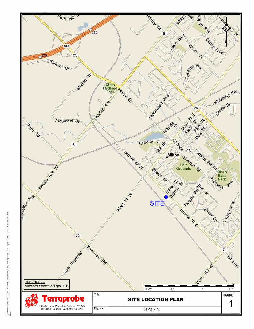
Terraprobe Inc. was retained by Victoria Park Community Homes to conduct a geotechnical investigation
for a proposed addition at the Community Housing Complex located in the southwest quadrant of the
intersection of Bronte Street South and Main Street West, in the Town of Milton, Ontario. The municipal
address of the property is 154 Bronte Street South, Milton.
This report encompasses the result of the geotechnical investigation carried out for the subject site to assess
its geotechnical suitability for the intended development and provide geotechnical design recommendations.
The field investigation consisted of advancing a total of five (5) exploratory boreholes. The geotechnical
investigation was conducted to determine the prevailing subsurface soil and groundwater conditions, and to
provide geotechnical engineering recommendations for the design of building foundations, floor slab, earth
pressure and earthquake design parameters. In addition, comments are also included on pertinent
construction aspects including excavation, backfill and groundwater control.
2. SITE AND PROJECT DESCRIPTION
The subject site is located in the southwest quadrant of Bronte Street South and Main Street West, in the
Town of Milton, Ontario. The site is bounded by Bronte Street to the east, Railway track to the west and
apartment buildings to the north and south. The municipal address of the property is 154 Bronte Street
South, Milton. The general location of the property is shown on enclosed Figure 1.
The site is a rectangular parcel of land located west of the Bronte Street South. The property is currently
occupied by an approximately twenty seven (27) unit apartment building and townhomes which provides
affordable housing for families and senior households. The existing two rows of the townhomes run in east-
west orientation and parallel to the access roadway running through the centre of the subject property. The
three storey apartment building is located at rear of the property with two associated at-grade asphalt parking
lots and landscaping areas.
It is proposed to construct a five (5) storey high above ground residential building consists of twenty four
(24) units at north-west portion of the existing townhomes. The first floor would include parking with
utilities, elevator and entrance. The development would be serviced with municipal water and sewer.
3. FIELD PROCEDURE
The field investigation was conducted on May 2, 2017, and consisted of drilling and sampling a total of five
(5) exploratory boreholes each extending to depth of about 6.5 m below existing ground surface located
approximately within the footprint of proposed development.
Victoria Park Community Homes September 25, 2017
154 Bronte Street, Milton, ON File No. 1-17-0214
Terraprobe Page 2
The borehole locations were established in the field by Terraprobe Inc. with respect to existing site features,
based on consultations with the client during the proposal stage. Various utility locate agencies were
contacted to clear the borehole locations of underground public utilities prior to drilling. Terraprobe retained
a private utility locate subcontractor to clear private underground utilities for the work area. The
approximate borehole locations are shown on the enclosed Borehole Location Plan (Figure 2).
The borehole ground surface elevations were surveyed by Terraprobe using a Trimble R10 GNSS System.
The Trimble R10 System uses the Global Navigation Satellite System and the Can-Net reference system to
determine target location and elevation. The Trimble R10 system is reported to have an accuracy of up to
10 mm horizontally and up to 30 mm vertically.
It should be noted that the elevations noted on the Borehole Logs are approximate, and provided only for the
purpose of relating borehole soil stratigraphy, and should not be used or relied on for other purposes.
The borings were drilled by a specialist drilling contractor using a track-mounted drill rig power auger. The
borings were advanced using non-continuous flight solid stem augers, and were sampled at regular interval
(at 0.75 m interval up to 3.0 m and 1.5 m interval below 3.0 m depth) with a conventional 50 mm diameter
split barrel samplers when the Standard Penetration Test (SPT) was carried out (ASTM D1586). The field
work (drilling, sampling and testing) was observed and recorded by a member of our field engineering staff,
who logged the borings and examined the samples as they were obtained.
All samples obtained during the field investigation were sealed into plastic jars and transported to our
laboratory for detailed inspection and testing. Borehole samples were examined (tactile) in detail by a
geotechnical engineer, and classified according to visual and index properties. Laboratory testing consisted
of water content determination on all samples, and a Sieve and Hydrometer analysis on three (3) selected soil
samples (Borehole 1, Sample 4; Borehole 3, Samples 3; Borehole 4, Sample 4) and Atterberg Limits tests
on two (2) selected soil samples (Borehole 1, Sample 4; Borehole 4, Sample 4) . The results of the
geotechnical laboratory testing are plotted on the enclosed Borehole Logs at the respective sampling depths.
The results of laboratory tests (Sieve and Hydrometer analysis and Atterberg Limits Test) are also
summarized in Section 4.4 of this report, and appended.
Ground water levels were observed in the open boreholes upon completion of drilling. Standpipe piezometer
comprising 19 mm diameter PVC tube were installed in two (2) selected boreholes (Boreholes 1 and 3) to
facilitate ground water level monitoring. The piezometers were fitted with a bentonite clay seal as shown
on the accompanying Borehole Logs. Water levels in the piezometers were measured on May 10, 2017
Victoria Park Community Homes September 25, 2017
154 Bronte Street, Milton, ON File No. 1-17-0214
Terraprobe Page 3
(about 1 week following the installation), and are plotted on the enclosed Borehole Logs. The results of
ground water level monitoring are presented in Section 4.5 of this report.
4. SUBSURFACE CONDITIONS
The results of the individual boreholes are summarized below and recorded on the accompanying Borehole
Logs. This summary is intended to correlate this data to assist in the interpretation of the subsurface
conditions encountered at the site. Please refer to enclosed Borehole Logs for stratigraphic and other details.
It should be noted that the soil conditions are confirmed at the borehole locations only and may vary between
and beyond the boreholes. The stratigraphic boundaries as shown on the Borehole Logs are based on a
non-continuous sampling. These boundaries represent an inferred transition between the various strata,
rather than a precise plane of geologic change.
In summary, all the boreholes encountered a topsoil layer at the ground surface, underlain by a zone of
weathered/disturbed soils which was in turn underlain by undisturbed native soil deposit extending to the
full depth of investigation (up to about 6.6 m below existing grade).
4.1 Topsoil
A surficial topsoil layer was encountered at all boreholes locations, varying in thickness from about 100 mm
(Boreholes 4) to 200 mm (Boreholes 1). The topsoil was dark brown to black in colour and predominately
consisted of a silt matrix.
4.2 Earth Fill/Weathered/Disturbed Soil Zone
A weathered/disturbed soil zone was encountered beneath the topsoil layer in Boreholes 1, 2, 3 and 5
extended to depths varying from about 0.6 m (Boreholes 3) to 0.8 m (Boreholes 1, 2 and 5) below existing
grade. The composition of the weathered/disturbed soil was similar to that of the underlying undisturbed
native soils but included trace amount of organics.
Earth fill material was encountered beneath the topsoil in Borehole 4 and extended to depth of about 1.5 m
below existing grade. The earth fill materials predominately consisted of clayey silt, with trace amounts of
gravel and organics.
The Standard Penetration Test results (‘N’ Values) obtained from the earth fill/weathered/disturbed materials
generally varied from 6 to 11 blows per 300 mm of penetration, indicating a firm consistency.
Victoria Park Community Homes September 25, 2017
154 Bronte Street, Milton, ON File No. 1-17-0214
Terraprobe Page 4
The measured moisture contents of the earth fill/weathered/disturbed soil samples ranged between 14 to 24
percent by weight, indicating a typically moist to wet condition.
4.3 Native Soil
Undisturbed native glacial till deposit predominantly comprising of clayey silt matrix with some sand to
sandy and trace amounts of gravel was encountered beneath the weathered/disturbed soil zone in Boreholes
1, 2, 3 and 5 and beneath the earthfill materials in Borehole 4 and extended to full depth of investigation in
all boreholes.
The Standard Penetration Test results (‘N’ Values) obtained from the clayey slit deposit varied from about
7 to 65 blows per 300 mm of penetration, indicating a firm to hard consistency (typically hard).
The measured moisture contents of the clayey slit samples ranged from about 7 to 18 percent by weight,
indicating a typically moist to wet condition.
A zone of sandy silt layer (about 400 mm thick) with numerous stone fragment was encountered in Borehole
1 at a depth of about 2.3 m below existing grade.
It should be noted that the glacial till deposits may contain larger sized particles (cobbles and boulders) that
are not specifically identified in the boreholes. Similarly, earthfill materials may also include larger sized
particles. The size and distribution of such obstructions cannot be predicted with borings, because the
borehole sampler size is insufficient to secure representative samples for the particles of this size.
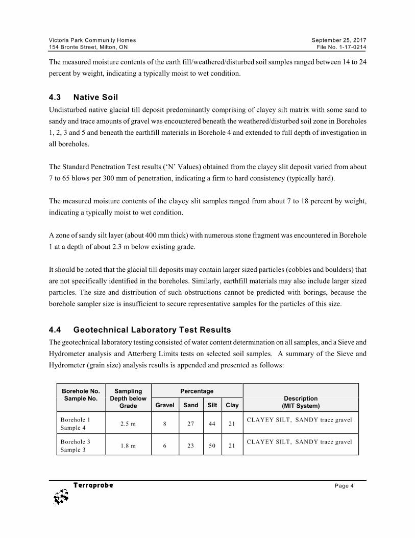
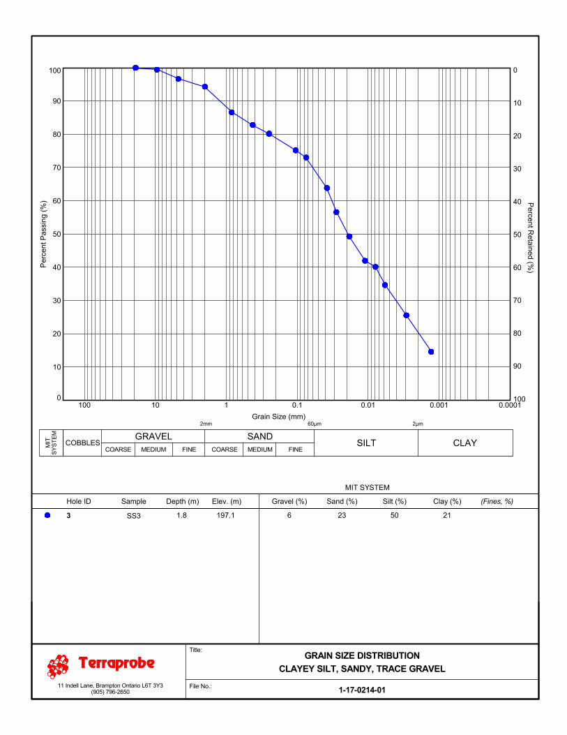
4.4 Geotechnical Laboratory Test Results
The geotechnical laboratory testing consisted of water content determination on all samples, and a Sieve and
Hydrometer analysis and Atterberg Limits tests on selected soil samples. A summary of the Sieve and
Hydrometer (grain size) analysis results is appended and presented as follows:
Borehole No.Sample No.
SamplingDepth below
Grade
PercentageDescription
(MIT System)Gravel Sand Silt Clay
Borehole 1
Sample 42.5 m 8 27 44 21
CLAYEY SILT, SANDY trace gravel
Borehole 3
Sample 31.8 m 6 23 50 21
CLAYEY SILT, SANDY trace gravel
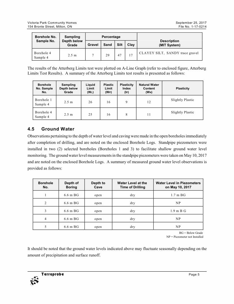
Victoria Park Community Homes September 25, 2017
154 Bronte Street, Milton, ON File No. 1-17-0214
Borehole No.Sample No.
SamplingDepth below
Grade
PercentageDescription
(MIT System)Gravel Sand Silt Clay
Terraprobe Page 5
Borehole 4
Sample 42.5 m 7 29 47 17
CLAYEY SILT, SANDY trace gravel
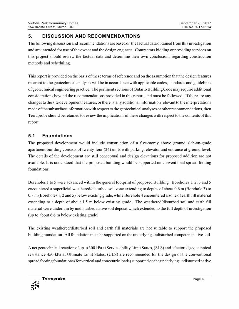
The results of the Atterberg Limits test were plotted on A-Line Graph (refer to enclosed figure, AtterbergLimits Test Results). A summary of the Atterberg Limits test results is presented as follows:
BoreholeNo. Sample
No.
SamplingDepth below
Grade
LiquidLimit(WL)
PlasticLimit(WP)
PlasticityIndex
(IP)
Natural WaterContent
(WN)Plasticity
Borehole 1
Sample 42.5 m 26 16 9 12
Slightly Plastic
Borehole 4
Sample 42.5 m 25 16 8 11
Slightly Plastic
4.5 Ground Water
Observations pertaining to the depth of water level and caving were made in the open boreholes immediately
after completion of drilling, and are noted on the enclosed Borehole Logs. Standpipe piezometers were
installed in two (2) selected boreholes (Boreholes 1 and 3) to facilitate shallow ground water level
monitoring. The ground water level measurements in the standpipe piezometers were taken on May 10, 2017
and are noted on the enclosed Borehole Logs. A summary of measured ground water level observations is
provided as follows:
BoreholeNo.
Depth ofBoring
Depth toCave
Water Level at the Time of Drilling
Water Level in Piezometerson May 10, 2017
1 6.6 m BG open dry 1.7 m BG
2 6.6 m BG open dry NP
3 6.6 m BG open dry 1.9 m B G
4 6.6 m BG open dry NP
5 6.6 m BG open dry NP
BG = Below Grade
NP = Piezometer not Installed
It should be noted that the ground water levels indicated above may fluctuate seasonally depending on the
amount of precipitation and surface runoff.
Victoria Park Community Homes September 25, 2017
154 Bronte Street, Milton, ON File No. 1-17-0214
Terraprobe Page 6
5. DISCUSSION AND RECOMMENDATIONS
The following discussion and recommendations are based on the factual data obtained from this investigation
and are intended for use of the owner and the design engineer. Contractors bidding or providing services on
this project should review the factual data and determine their own conclusions regarding construction
methods and scheduling.
This report is provided on the basis of these terms of reference and on the assumption that the design features
relevant to the geotechnical analyses will be in accordance with applicable codes, standards and guidelines
of geotechnical engineering practice. The pertinent sections of Ontario Building Code may require additional
considerations beyond the recommendations provided in this report, and must be followed. If there are any
changes to the site development features, or there is any additional information relevant to the interpretations
made of the subsurface information with respect to the geotechnical analyses or other recommendations, then
Terraprobe should be retained to review the implications of these changes with respect to the contents of this
report.
5.1 Foundations
The proposed development would include construction of a five-storey above ground slab-on-grade
apartment building consists of twenty-four (24) units with parking, elevator and entrance at ground level.
The details of the development are still conceptual and design elevations for proposed addition are not
available. It is understood that the proposed building would be supported on conventional spread footing
foundations.
Boreholes 1 to 5 were advanced within the general footprint of proposed Building. Boreholes 1, 2, 3 and 5
encountered a superficial weathered/disturbed soil zone extending to depths of about 0.6 m (Borehole 3) to
0.8 m (Boreholes 1, 2 and 5) below existing grade, while Borehole 4 encountered a zone of earth fill material
extending to a depth of about 1.5 m below existing grade. The weathered/disturbed soil and earth fill
material were underlain by undisturbed native soil deposit which extended to the full depth of investigation
(up to about 6.6 m below existing grade).
The existing weathered/disturbed soil and earth fill materials are not suitable to support the proposed
building foundation. All foundation must be supported on the underlying undisturbed competent native soil.
A net geotechnical reaction of up to 300 kPa at Serviceability Limit States, (SLS) and a factored geotechnical
resistance 450 kPa at Ultimate Limit States, (ULS) are recommended for the design of the conventional
spread footing foundations (for vertical and concentric loads) supported on the underlying undisturbed native
Victoria Park Community Homes September 25, 2017
154 Bronte Street, Milton, ON File No. 1-17-0214
Terraprobe Page 7
soils of very stiff to hard consistency at a minimum depth of 1.5 m at Boreholes 1, 2, 3 and 5, and 1.8 m
below existing grade at Borehole 4 locations..
The minimum width of the continuous strip footings must be 500 mm and the minimum size of isolated
footings must be 900 mm x 900 mm regardless of loading considerations, in conjunction with the above
recommended geotechnical resistance. The geotechnical resistance(s) as recommended above allow for up
to 25 mm of total settlement. This settlement will occur as load is applied and is linear elastic and non-
recoverable. Differential settlement is a function of spacing, loading and foundation size.
5.1.1 Foundation Installation
It is recommended that all excavated footing bases must be evaluated by a qualified geotechnical engineer
to ensure that the founding soils exposed at the excavation base are consistent with the design bearing
pressure intended by the geotechnical engineer. All exterior foundations and foundations in unheated areas
should be provided with a minimum of 1.2 m of earth cover for frost protection or alternative equivalent
insulation.
Prior to pouring foundation concrete, the foundation subgrade should be cleaned of all deleterious materials
such as topsoil, fill, wet, softened, disturbed or caved materials, as well as any standing water. If
construction proceeds during freezing weather conditions, adequate temporary frost protection for the
foundation subgrade and concrete must be provided.
It is noted that the native soils tend to weather rapidly and deteriorate on exposure to the atmosphere or
surface water. Hence, foundation bases which remain open for an extended period of time should be
protected by a skim coat of lean concrete.
5.2 Slab-on-Grade
Conventional lightly loaded concrete slab should be placed on at least 150 mm of granular base (OPSS.
MUNI 1010 Granular “A” or 19 mm crusher run limestone; or 19 mm clear stone, OPSS. MUNI 1004)
compacted to a minimum of 98 percent Standard Proctor Maximum Dry Density (SPMDD) or vibrated to
a dense state in case of a clear stone type material. The granular base should be placed on undisturbed native
soil subgrade, or on clean earth fill subgrade compacted to a minimum of 95 percent SPMDD. The subgrade
should be assessed by a geotechnical engineer (or its representative) prior to the placement of granular base.
Any soft or wet subgrade areas as well as areas containing excessive amounts of deleterious materials must
be subexcavated, and backfilled with suitably compacted clean earth fill as noted above.
Victoria Park Community Homes September 25, 2017
154 Bronte Street, Milton, ON File No. 1-17-0214
Terraprobe Page 8
Regardless of the approach to slab construction, the floor slabs that are to have bonded floor finish (such as
tiles with adhesives) should be provided with a capillary moisture break and a vapour barrier. The floor
manufacturers have specific requirements for moisture and vapour barrier, therefore, the floor designer/
architect must ensure that a provision of appropriate moisture and vapour barrier conforming to specific floor
finish product requirements is incorporated in the project specifications. Adequate testing must be carried
out to ensure acceptable levels of moisture and relative humidity in the concrete slab prior to the installation
of floor finish. Studies indicate that a provision of 200 mm thick 19 mm clearstone base (OPSS 1004) under
the slab helps provide a good capillary moisture break provided the granular base is positively drained.
However, this provision does not provide protection against moisture vapour migration and/or replace the
floor manufacturers’ specific requirement(s) for a moisture and vapour barrier.
The under-slab vapour retarder specifications, selection and installation shall conform to ASTM E1745 and
ASTM E1643. The moisture vapour measurement tests shall conform to RH: ASTM F2170, RH: ASTM
F2420 and Calcium Chloride: ASTM F1869. The Surface Applied Moisture Vapour Barrier system shall
meet the guidelines established in ASTM F3010-13.
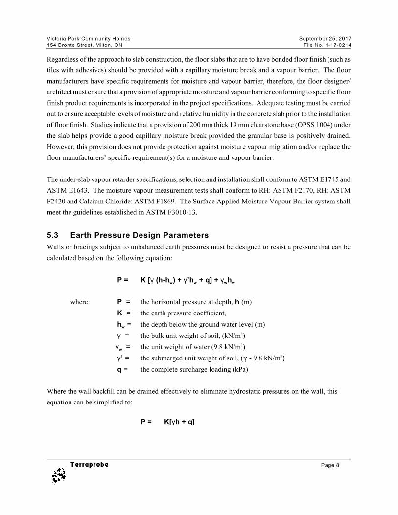
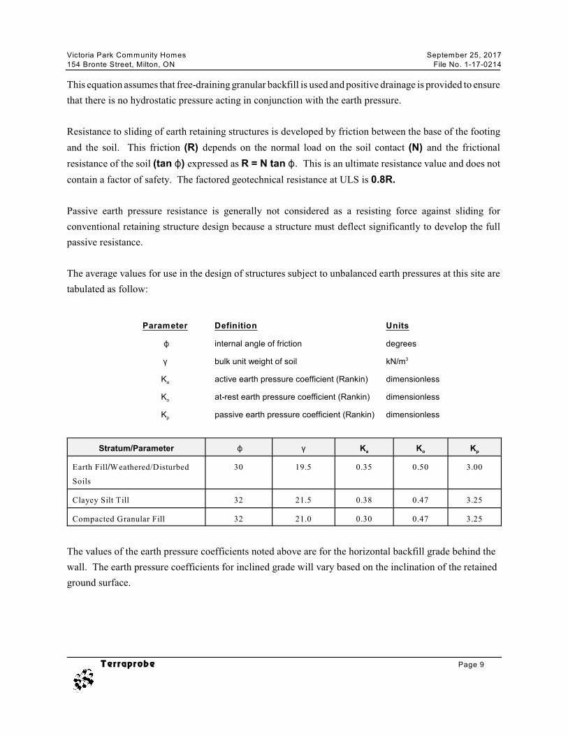
5.3 Earth Pressure Design Parameters
Walls or bracings subject to unbalanced earth pressures must be designed to resist a pressure that can be
calculated based on the following equation:
w w w wP = K [( (h-h ) + (’h + q] + ( h
where: P = the horizontal pressure at depth, h (m)
K = the earth pressure coefficient,
wh = the depth below the ground water level (m)
( = the bulk unit weight of soil, (kN/m )3
w ( = the unit weight of water (9.8 kN/m )3
(’ = the submerged unit weight of soil, (( - 9.8 kN/m )3
q = the complete surcharge loading (kPa)
Where the wall backfill can be drained effectively to eliminate hydrostatic pressures on the wall, this
equation can be simplified to:
P = K[(h + q]
Victoria Park Community Homes September 25, 2017
154 Bronte Street, Milton, ON File No. 1-17-0214
Terraprobe Page 9
This equation assumes that free-draining granular backfill is used and positive drainage is provided to ensure
that there is no hydrostatic pressure acting in conjunction with the earth pressure.
Resistance to sliding of earth retaining structures is developed by friction between the base of the footing
and the soil. This friction (R) depends on the normal load on the soil contact (N) and the frictional
resistance of the soil (tan N) expressed as R = N tan N. This is an ultimate resistance value and does not
contain a factor of safety. The factored geotechnical resistance at ULS is 0.8R.
Passive earth pressure resistance is generally not considered as a resisting force against sliding for
conventional retaining structure design because a structure must deflect significantly to develop the full
passive resistance.
The average values for use in the design of structures subject to unbalanced earth pressures at this site are
tabulated as follow:
Parameter Definition Units
N internal angle of friction degrees
( bulk unit weight of soil kN/m3
aK active earth pressure coefficient (Rankin) dimensionless
oK at-rest earth pressure coefficient (Rankin) dimensionless
pK passive earth pressure coefficient (Rankin) dimensionless
a o pStratum/Parameter N ( K K K
Earth Fill/Weathered/Disturbed
Soils
30 19.5 0.35 0.50 3.00
Clayey Silt Till 32 21.5 0.38 0.47 3.25
Compacted Granular Fill 32 21.0 0.30 0.47 3.25
The values of the earth pressure coefficients noted above are for the horizontal backfill grade behind the
wall. The earth pressure coefficients for inclined grade will vary based on the inclination of the retained
ground surface.
Victoria Park Community Homes September 25, 2017
154 Bronte Street, Milton, ON File No. 1-17-0214
Terraprobe Page 10
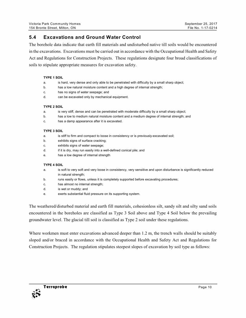
5.4 Excavations and Ground Water Control
The borehole data indicate that earth fill materials and undisturbed native till soils would be encountered
in the excavations. Excavations must be carried out in accordance with the Occupational Health and Safety
Act and Regulations for Construction Projects. These regulations designate four broad classifications of
soils to stipulate appropriate measures for excavation safety.
TYPE 1 SOIL
a. is hard, very dense and only able to be penetrated with difficulty by a small sharp object;
b. has a low natural moisture content and a high degree of internal strength;
c. has no signs of water seepage; and
d. can be excavated only by mechanical equipment.
TYPE 2 SOIL
a. is very stiff, dense and can be penetrated with moderate difficulty by a small sharp object;
b. has a low to medium natural moisture content and a medium degree of internal strength; and
c. has a damp appearance after it is excavated.
TYPE 3 SOIL
a. is stiff to firm and compact to loose in consistency or is previously-excavated soil;
b. exhibits signs of surface cracking;
c. exhibits signs of water seepage;
d. if it is dry, may run easily into a well-defined conical pile; and
e. has a low degree of internal strength
TYPE 4 SOIL
a. is soft to very soft and very loose in consistency, very sensitive and upon disturbance is significantly reduced
in natural strength;
b. runs easily or flows, unless it is completely supported before excavating procedures;
c. has almost no internal strength;
d. is wet or muddy; and
e. exerts substantial fluid pressure on its supporting system.
The weathered/disturbed material and earth fill materials, cohesionless silt, sandy silt and silty sand soils
encountered in the boreholes are classified as Type 3 Soil above and Type 4 Soil below the prevailing
groundwater level. The glacial till soil is classified as Type 2 soil under these regulations.
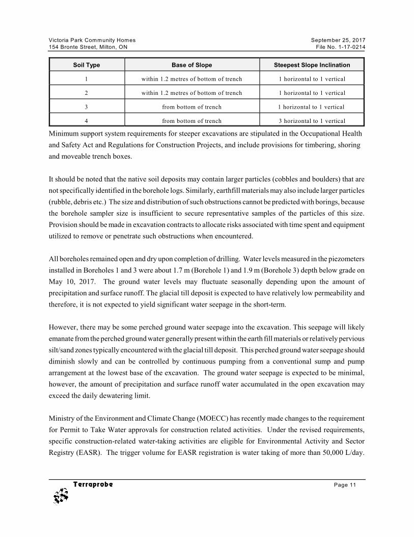
Where workmen must enter excavations advanced deeper than 1.2 m, the trench walls should be suitably
sloped and/or braced in accordance with the Occupational Health and Safety Act and Regulations for
Construction Projects. The regulation stipulates steepest slopes of excavation by soil type as follows:
Victoria Park Community Homes September 25, 2017
154 Bronte Street, Milton, ON File No. 1-17-0214
Terraprobe Page 11
Soil Type Base of Slope Steepest Slope Inclination
1 within 1.2 metres of bottom of trench 1 horizontal to 1 vertical
2 within 1.2 metres of bottom of trench 1 horizontal to 1 vertical
3 from bottom of trench 1 horizontal to 1 vertical
4 from bottom of trench 3 horizontal to 1 vertical
Minimum support system requirements for steeper excavations are stipulated in the Occupational Health
and Safety Act and Regulations for Construction Projects, and include provisions for timbering, shoring
and moveable trench boxes.
It should be noted that the native soil deposits may contain larger particles (cobbles and boulders) that are
not specifically identified in the borehole logs. Similarly, earthfill materials may also include larger particles
(rubble, debris etc.) The size and distribution of such obstructions cannot be predicted with borings, because
the borehole sampler size is insufficient to secure representative samples of the particles of this size.
Provision should be made in excavation contracts to allocate risks associated with time spent and equipment
utilized to remove or penetrate such obstructions when encountered.
All boreholes remained open and dry upon completion of drilling. Water levels measured in the piezometers
installed in Boreholes 1 and 3 were about 1.7 m (Borehole 1) and 1.9 m (Borehole 3) depth below grade on
May 10, 2017. The ground water levels may fluctuate seasonally depending upon the amount of
precipitation and surface runoff. The glacial till deposit is expected to have relatively low permeability and
therefore, it is not expected to yield significant water seepage in the short-term.
However, there may be some perched ground water seepage into the excavation. This seepage will likely
emanate from the perched ground water generally present within the earth fill materials or relatively pervious
silt/sand zones typically encountered with the glacial till deposit. This perched ground water seepage should
diminish slowly and can be controlled by continuous pumping from a conventional sump and pump
arrangement at the lowest base of the excavation. The ground water seepage is expected to be minimal,
however, the amount of precipitation and surface runoff water accumulated in the open excavation may
exceed the daily dewatering limit.
Ministry of the Environment and Climate Change (MOECC) has recently made changes to the requirement
for Permit to Take Water approvals for construction related activities. Under the revised requirements,
specific construction-related water-taking activities are eligible for Environmental Activity and Sector
Registry (EASR). The trigger volume for EASR registration is water taking of more than 50,000 L/day.
Victoria Park Community Homes September 25, 2017
154 Bronte Street, Milton, ON File No. 1-17-0214
Terraprobe Page 12
This includes the ground water that is collected in the open excavation as well as any precipitation or surface
run-off that enters the excavation.
5.5 Backfill
The existing earth fill/weathered/disturbed materials containing excessive amounts of organics should not
be reused as backfill in settlement sensitive areas, such as beneath floor slabs. However, these materials may
be stockpiled and reused for landscaping purposes. The earth fill materials with only trace amounts of
organic inclusion may be utilized as backfill. The selection and sorting of earth fill materials should be
conducted under the supervision of a geotechnical engineer.
A visual inspection of the borehole soil samples retrieved during the sub-surface investigation indicates that
the undisturbed native soils encountered in the boreholes may be used for subgrade preparation and
backfilling purposes.
The moisture content of the backfill soils should be within 3 percent of their optimum moisture content. The
undisturbed native soils and clean earth fill materials are considered suitable for backfilling provided these
soils are within 3 percent of the optimum moisture content. Any soil material with 3 percent or higher in-situ
moisture content than its optimum moisture content could be put aside to dry, or be tilled to reduce the
moisture content so that it can be effectively compacted. Alternatively, materials of higher moisture content
could be wasted and replaced with imported material which can be readily compacted.
In settlement sensitive areas (beneath the floor slabs), the backfill should consist of clean earth and should
be placed in lifts of 150 mm thicknesses or less, and heavily compacted to a minimum of 95 percent SPMDD
at a water content close to optimum. The soils encountered on the site will be best compacted with a heavy
sheepsfoot type roller.
It should be noted that the site soils are generally not free draining, and will be difficult to handle and
compact should they become wetter as a result of inclement weather or seepage. Hence, it can be expected
that earthworks will be difficult during the wet periods (i.e., spring and fall) of the year, and may result in
increased earthwork costs.
5.6 Pavement Design
The proposed works may include construction of asphalt paved parking areas and driveways/access routes.
As noted before, all boreholes encountered surficial topsoil layer at the ground surface underlain by
weathered/disturbed materials extending to depth of about 0.8 m (boreholes 1, 2, 3 and 5) and earthfill
Victoria Park Community Homes September 25, 2017
154 Bronte Street, Milton, ON File No. 1-17-0214
Terraprobe Page 13
materials extending to depth of about 1.5 m (Borehole 4). Therefore, the pavement subgrade for the
proposed development is expected to consist of weathered/disturbed and/or earth fill materials.
The pavement subgrade should be proof-rolled with a heavy rubber tire vehicle (such as a grader) and any
loose, soft, wet or unstable areas should be sub-excavated, and backfilled with clean earth fill material placed
in 150 mm thick lifts and compacted to a minimum of 98 percent SPMDD. Local subexcavation in some
areas may be required due to loose/soft, wet and incompetent subgrade conditions or excessive topsoil/
organic presence, as identified during the proof roll.
The existing native and earth fill/weathered/disturbed materials encountered on the site may be utilized for
subgrade preparation provided they do not contain excessive amounts of organics and deleterious materials,
as well as their in-situ moisture content is within 3 percent of the optimum moisture content. The selection
and sorting of these soils for reuse should be conducted under the supervision of a geotechnical engineer.
Pavement subgrade fill material should be compacted to a minimum of 95 percent SPMDD, while the upper
zone (within 1.2 m of the design subgrade) should be compacted to a minimum of 98 percent SPMDD.
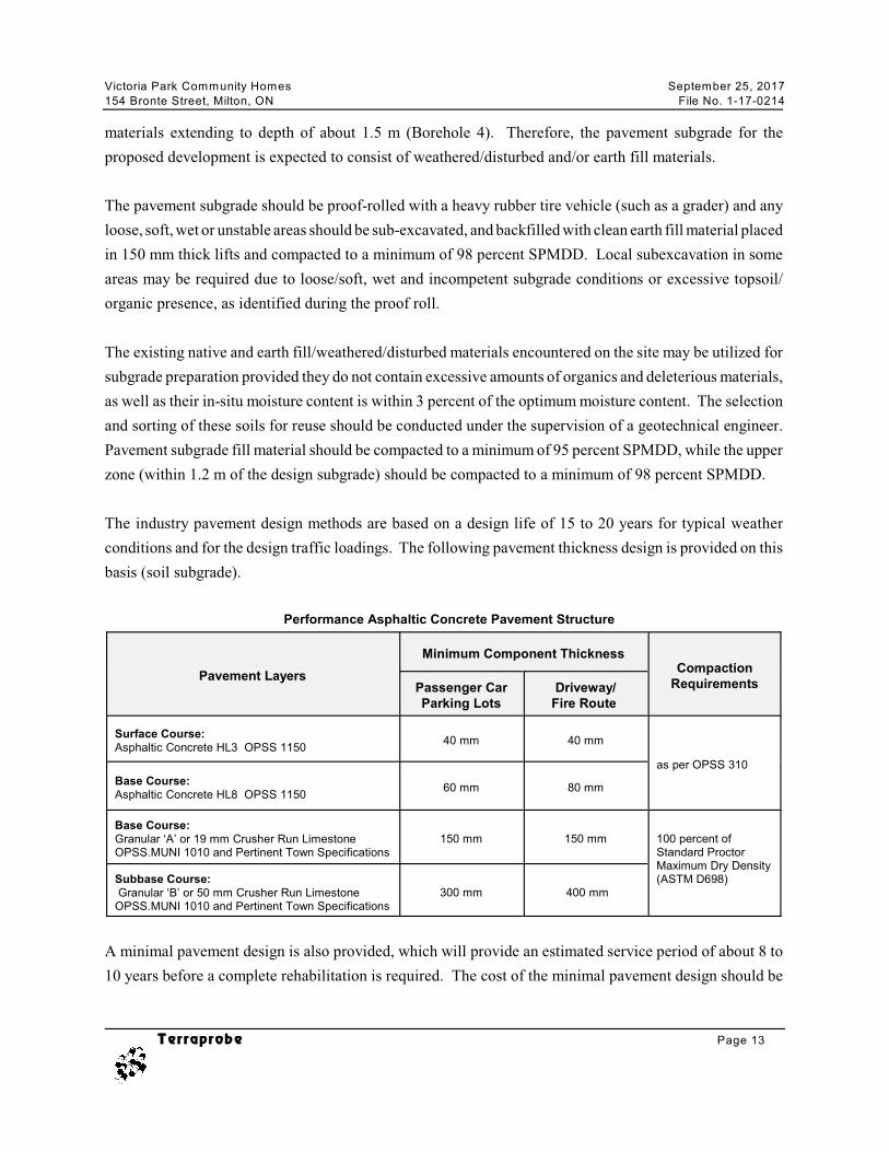
The industry pavement design methods are based on a design life of 15 to 20 years for typical weather
conditions and for the design traffic loadings. The following pavement thickness design is provided on this
basis (soil subgrade).
Performance Asphaltic Concrete Pavement Structure
Pavement Layers
Minimum Component ThicknessCompaction
RequirementsPassenger CarParking Lots
Driveway/Fire Route
Surface Course:Asphaltic Concrete HL3 OPSS 1150
40 mm 40 mm
as per OPSS 310
Base Course:Asphaltic Concrete HL8 OPSS 1150
60 mm 80 mm
Base Course:Granular ‘A’ or 19 mm Crusher Run LimestoneOPSS.MUNI 1010 and Pertinent Town Specifications
150 mm 150 mm 100 percent ofStandard ProctorMaximum Dry Density(ASTM D698)Subbase Course:
Granular ‘B’ or 50 mm Crusher Run LimestoneOPSS.MUNI 1010 and Pertinent Town Specifications
300 mm 400 mm
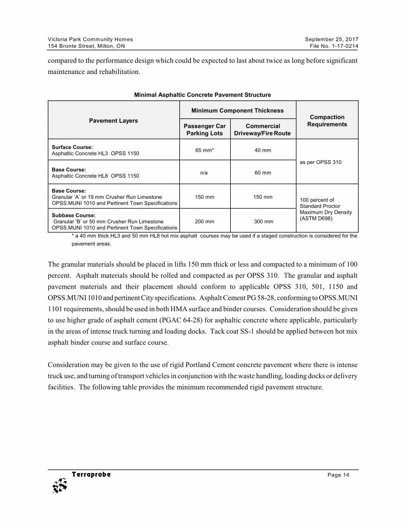
A minimal pavement design is also provided, which will provide an estimated service period of about 8 to
10 years before a complete rehabilitation is required. The cost of the minimal pavement design should be
Victoria Park Community Homes September 25, 2017
154 Bronte Street, Milton, ON File No. 1-17-0214
Terraprobe Page 14
compared to the performance design which could be expected to last about twice as long before significant
maintenance and rehabilitation.
Minimal Asphaltic Concrete Pavement Structure
Pavement Layers
Minimum Component ThicknessCompaction
RequirementsPassenger CarParking Lots
CommercialDriveway/Fire Route
Surface Course:Asphaltic Concrete HL3 OPSS 1150
65 mm* 40 mm
as per OPSS 310
Base Course:Asphaltic Concrete HL8 OPSS 1150
n/a 60 mm
Base Course:Granular ‘A’ or 19 mm Crusher Run LimestoneOPSS.MUNI 1010 and Pertinent Town Specifications
150 mm 150 mm100 percent ofStandard ProctorMaximum Dry Density(ASTM D698)
Subbase Course: Granular ‘B’ or 50 mm Crusher Run LimestoneOPSS.MUNI 1010 and Pertinent Town Specifications
200 mm 300 mm
* a 40 mm thick HL3 and 50 mm HL8 hot mix asphalt courses may be used if a staged construction is considered for the
pavement areas.
The granular materials should be placed in lifts 150 mm thick or less and compacted to a minimum of 100
percent. Asphalt materials should be rolled and compacted as per OPSS 310. The granular and asphalt
pavement materials and their placement should conform to applicable OPSS 310, 501, 1150 and
OPSS.MUNI 1010 and pertinent City specifications. Asphalt Cement PG 58-28, conforming to OPSS.MUNI
1101 requirements, should be used in both HMA surface and binder courses. Consideration should be given
to use higher grade of asphalt cement (PGAC 64-28) for asphaltic concrete where applicable, particularly
in the areas of intense truck turning and loading docks. Tack coat SS-1 should be applied between hot mix
asphalt binder course and surface course.
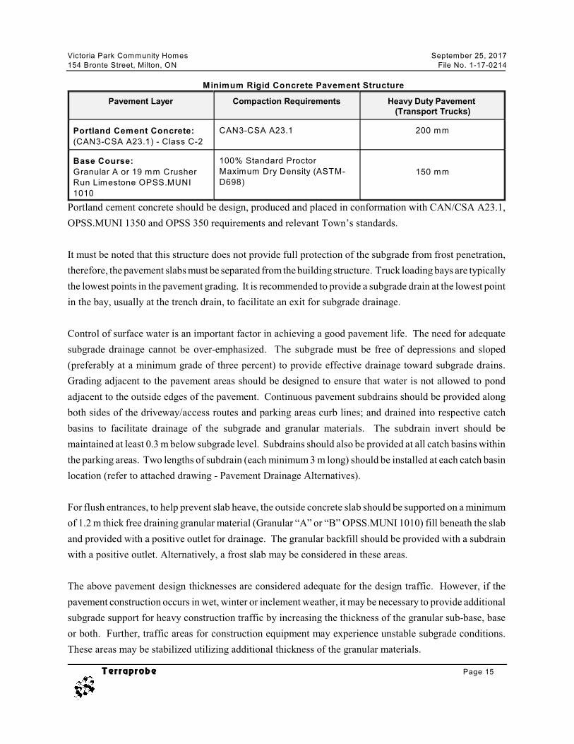
Consideration may be given to the use of rigid Portland Cement concrete pavement where there is intense
truck use, and turning of transport vehicles in conjunction with the waste handling, loading docks or delivery
facilities. The following table provides the minimum recommended rigid pavement structure.
Victoria Park Community Homes September 25, 2017
154 Bronte Street, Milton, ON File No. 1-17-0214
Terraprobe Page 15
Minimum Rigid Concrete Pavement Structure
Pavement Layer Compaction Requirements Heavy Duty Pavement (Transport Trucks)
Portland Cement Concrete:
(CAN3-CSA A23.1) - Class C-2
CAN3-CSA A23.1 200 mm
Base Course:
Granular A or 19 mm Crusher
Run Limestone OPSS.MUNI
1010
100% Standard Proctor
Maximum Dry Density (ASTM-
D698)150 mm
Portland cement concrete should be design, produced and placed in conformation with CAN/CSA A23.1,
OPSS.MUNI 1350 and OPSS 350 requirements and relevant Town’s standards.
It must be noted that this structure does not provide full protection of the subgrade from frost penetration,
therefore, the pavement slabs must be separated from the building structure. Truck loading bays are typically
the lowest points in the pavement grading. It is recommended to provide a subgrade drain at the lowest point
in the bay, usually at the trench drain, to facilitate an exit for subgrade drainage.
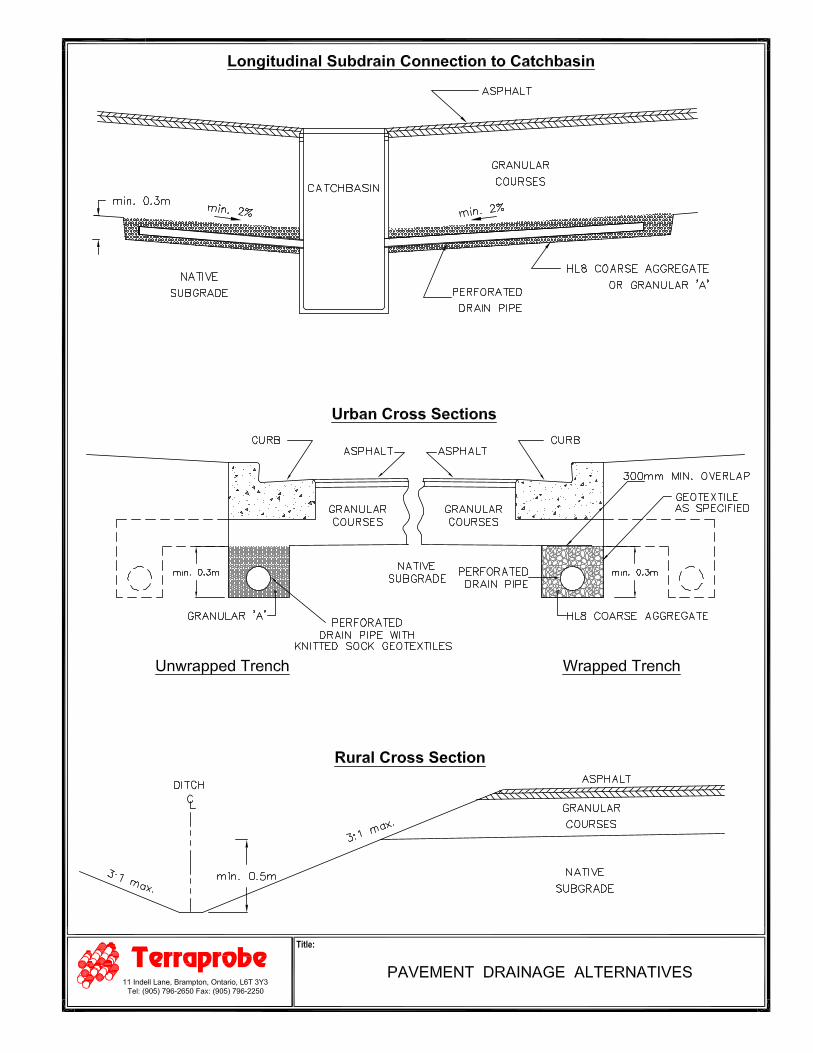
Control of surface water is an important factor in achieving a good pavement life. The need for adequate
subgrade drainage cannot be over-emphasized. The subgrade must be free of depressions and sloped
(preferably at a minimum grade of three percent) to provide effective drainage toward subgrade drains.
Grading adjacent to the pavement areas should be designed to ensure that water is not allowed to pond
adjacent to the outside edges of the pavement. Continuous pavement subdrains should be provided along
both sides of the driveway/access routes and parking areas curb lines; and drained into respective catch
basins to facilitate drainage of the subgrade and granular materials. The subdrain invert should be
maintained at least 0.3 m below subgrade level. Subdrains should also be provided at all catch basins within
the parking areas. Two lengths of subdrain (each minimum 3 m long) should be installed at each catch basin
location (refer to attached drawing - Pavement Drainage Alternatives).
For flush entrances, to help prevent slab heave, the outside concrete slab should be supported on a minimum
of 1.2 m thick free draining granular material (Granular “A” or “B” OPSS.MUNI 1010) fill beneath the slab
and provided with a positive outlet for drainage. The granular backfill should be provided with a subdrain
with a positive outlet. Alternatively, a frost slab may be considered in these areas.
The above pavement design thicknesses are considered adequate for the design traffic. However, if the
pavement construction occurs in wet, winter or inclement weather, it may be necessary to provide additional
subgrade support for heavy construction traffic by increasing the thickness of the granular sub-base, base
or both. Further, traffic areas for construction equipment may experience unstable subgrade conditions.
These areas may be stabilized utilizing additional thickness of the granular materials.
Victoria Park Community Homes September 25, 2017
154 Bronte Street, Milton, ON File No. 1-17-0214
Terraprobe Page 16
It should be noted that in addition to the adherence to the above pavement design recommendations, a close
control on the pavement construction process will also be required in order to obtain the designed pavement
life. It is recommended that regular inspection and testing should be conducted during the pavement
construction to confirm material quality, thickness, and to ensure adequate compaction.
5.7 Pipe Bedding
The design details and invert elevations of the underground utilities are not available at the time of
preparation of this report. As noted before, the site stratigraphy predominantly consists of earth fill materials
underlain by undisturbed native soil deposit extending to the full depth of investigation. The undisturbed
native materials and approved compacted earth fill will be suitable for support of buried services on a
conventional well graded granular base material. It is recommended that the utility subgrade be inspected
by a geotechnical engineer or its representative during construction. The utility subgrade may require
stabilization as deemed necessary based on the subgrade assessment, particularly if it consists of earth fill
or wet, loose/soft materials. If the disturbance of the trench base has occurred, such as due to ground water
seepage, or construction traffic, the disturbed soils should be subexcavated and replaced with suitably
compacted granular fill.
Granular bedding material should consist of a well graded, free draining soil, such as OPSS Granular “A”
or 19 mm Crusher Run Limestone or its equivalent as per the pertinent Town/Region specifications. The
bedding materials should be placed in 150 mm thick lifts and compacted to a minimum of 95 percent
SPMDD or vibrated/tempted to a dense state in case of a clear stone bedding.
A clear stone type bedding may be considered if approved by the Town/Region, however, on a silt/sand
subgrade it must be utilized only in conjunction with a suitable geotextile filter (Terrafix 270R or
equivalent). Without proper filtering, there may be entry of fines from the subgrade soils into the bedding.
This loss of ground could result in loss of support to the pipes and possible future settlements.
5.8 Earthquake Design Parameters
Ontario Building Code (2012) stipulates the methodology for earthquake design analysis, as set out in
Subsection 4.1.8.7. The determination of the type of analysis is predicated on the importance of the
structure, the spectral response acceleration and the site classification.
The parameters for determination of Site Classification for Seismic Site Response are set out in Table
4.1.8.4A of the Ontario Building Code (2012). The classification is based on the determination of the
Victoria Park Community Homes September 25, 2017
154 Bronte Street, Milton, ON File No. 1-17-0214
Terraprobe Page 17
saverage shear wave velocity in the top 30 meters of the site stratigraphy, where shear wave velocity (v )
measurements have been taken. Alternatively, the classification is estimated on the basis of rational analysis
uof undrained shear strength (s ) or penetration resistance (N-values).
Shear wavevelocity
Undrainedshear strength
SPT – values
The undisturbed native glacial till deposit below foundation level is expected to consist of typically very stiff
to hard (typically hard) consistency with undrained shear strength of 100 kPa. It is expected that the deeper
stratigraphy in this area is at least as competent as the lower proven stratum. On this basis, the site
designation for seismic analysis is Class C, according to Table 4.1.8.4.A of the Ontario Building Code.
Tables 4.1.8.4.B and 4.1.8.4.C. of the Ontario Building Code provide, the applicable acceleration and
velocity based site coefficients.
aSite Class Values of F (acceleration-based site coefficient)
a a a a aS (0.2) # 0.25 S (0.2) = 0.50 S (0.2) = 0.75 S (0.2) = 1.00 S (0.2)$ 1.25
C 1.0 1.0 1.0 1.0 1.0
vSite Class Values of F (velocity-based site coefficient)
a a a a aS (1.0) # 0.1 S (1.0) = 0.2 S (1.0) = 0.3 S (1.0) = 0.4 S (1.0) $ 0.5
C 1.0 1.0 1.0 1.0 1.0
It should be noted that the above site seismic designation is estimated on the basis of rational analysis of
the Undrained Shear Strength obtained from the boreholes advanced only to a depth of about 6.5 m
below grade. Consideration could be given to conduct a site specific Multichannel Analysis of Surface
Waves (MASW) to determine the average shear wave velocity in the top 30 metres of the site
stratigraphy. Terraprobe can arrange for this test, and provide results as a separate addendum letter.
Victoria Park Community Homes September 25, 2017
154 Bronte Street, Milton, ON File No. 1-17-0214
Terraprobe Page 18
6. LIMITATIONS AND RISK
It must be recognized that there are special risks whenever engineering or related disciplines are applied to
identify subsurface conditions. A comprehensive sampling and testing programme implemented in
accordance with the most stringent level of care may fail to detect certain conditions. Terraprobe has
assumed for the purposes of providing advice, that the conditions that exist between sampling points are
similar to those found at the sample locations. The conditions that Terraprobe has interpreted to exist
between sampling points can differ from those that actually exist.
It must also be recognized that the passage of time, natural occurrences, and direct or indirect human
intervention at or near the site have the potential to alter subsurface conditions.
The discussion and recommendations are based on the factual data obtained from the investigation and are
intended for use by the owner and its retained designers in the design phase of the project. Since the project
is still in the design stage, all aspects of the project relative to the subsurface conditions cannot be
anticipated. Terraprobe should review the design drawings and specifications prior to the construction of
this work. If there are changes to the project scope and development features, the interpretations made of
the subsurface information, the geotechnical design parameters and comments relating to constructibility
issues and quality control may not be relevant to the revised project in part or complete. Terraprobe should
be retained to review the implications of these changes with respect to the contents of this report.
The investigation at this site was conceived and executed to provide information for project design. It may
not be possible to drill a sufficient number of boreholes or samples and report them in a way that would
provide all the subsurface information that could have an effect on construction costs, techniques,
equipment, and scheduling. Contractors bidding on or undertaking work on this project should therefore,
in this light, be directed to decide on their own investigations, as well as their own interpretations of the
factual investigation results. They should be cognizant of the risks implicit in subsurface investigation
activities so that they may draw their own conclusions as to how the subsurface conditions may affect them.
This report was prepared for the express use of Victoria Park Community Homes and its retained design
consultants. It is not for use by others. This report is copyright of Terraprobe Inc. and no part of this report
may be reproduced by any means, in any forms, without the prior written permission of Terraprobe Inc. and
Victoria Park Community Homes, who are the authorized users.
It is recognized that the regulatory agencies in their capacities as the planning and building authorities under
Provincial statues, will make use of and rely upon this report, cognizant of the limitations thereof, both
expressed and implied.
APPENDIX
TERRAPROBE INC.
Terraprobe ABBREVIATIONS AND TERMINOLOGY
Terraprobe Inc.Greater Toronto Hamilton – Niagara Central Ontario Northern Ontario 11 Indell Lane 903 Barton Street, Unit 22 220 Bayview Drive, Unit 25 1012 Kelly Lake Rd., Unit 1 Brampton, Ontario L6T 3Y3 Stoney Creek, Ontario L8E 5P5 Barrie, Ontario L4N 4Y8 Sudbury, Ontario P3E 5P4 (905) 796-2650 Fax: 796-2250 (905) 643-7560 Fax: 643-7559 (705) 739-8355 Fax: 739-8369 (705) 670-0460 Fax: 670-0558
www.terraprobe.ca
SAMPLING METHODS AS auger sample CORE cored sample DP direct push FV field vane GS grab sample SS split spoon ST shelby tube WS wash sample
PENETRATION RESISTANCE Standard Penetration Test (SPT) resistance ('N' values) is defined as the number of blows by a hammer weighing 63.6 kg (140 lb.) falling freely for a distance of 0.76 m (30 in.) required to advance a standard 50 mm (2 in.) diameter split spoon sampler for a distance of 0.3 m (12 in.). Dynamic Cone Test (DCT) resistance is defined as the number of blows by a hammer weighing 63.6 kg (140 lb.) falling freely for a distance of 0.76 m (30 in.) required to advance a conical steel point of 50 mm (2 in.) diameter and with 60° sides on 'A' size drill rods for a distance of 0.3 m (12 in.)."
COHESIONLESS SOILS
Compactness ‘N’ value
very loose < 4 loose 4 – 10 compact 10 – 30 dense 30 – 50 very dense > 50
COHESIVE SOILS
Consistency ‘N’ value Undrained Shear Strength (kPa)
very soft < 2 < 12 soft 2 – 4 12 – 25 firm 4 – 8 25 – 50 stiff 8 – 15 50 – 100 very stiff 15 – 30 100 – 200 hard > 30 > 200
COMPOSITION Term (e.g) % by weight
trace silt < 10 some silt 10 – 20 silty 20 – 35 sand and silt > 35
TESTS AND SYMBOLS
MH mechanical sieve and hydrometer analysis
w, wc water content
wL, LL liquid limit
wP, PL plastic limit
IP, PI plasticity index
k coefficient of permeability
γ soil unit weight, bulk
φ’ internal friction angle
c’ effective cohesion
cu undrained shear strength
Unstabilized water level
1st water level measurement
2nd water level measurement
Most recent water level measurement
Undrained shear strength from field vane (with sensitivity)
Cc compression index
cv coefficient of consolidation
mv coefficient of compressibility
e void ratio
FIELD MOISTURE DESCRIPTIONS Damp refers to a soil sample that does not exhibit any observable pore water from field/hand inspection.
Moist refers to a soil sample that exhibits evidence of existing pore water (e.g. sample feels cool, cohesive soil is at plastic limit) but does not have visible pore water
Wet refers to a soil sample that has visible pore water
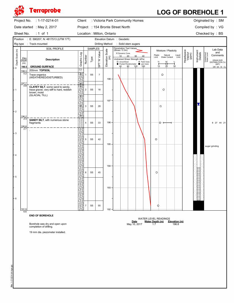
BOREHOLELOGS
TERRAPROBE INC.
SS
SS
SS
SS
SS
SS
SS
WATER LEVEL READINGSDate Water Depth (m) Elevation (m)
May 10, 2017 1.7 196.8
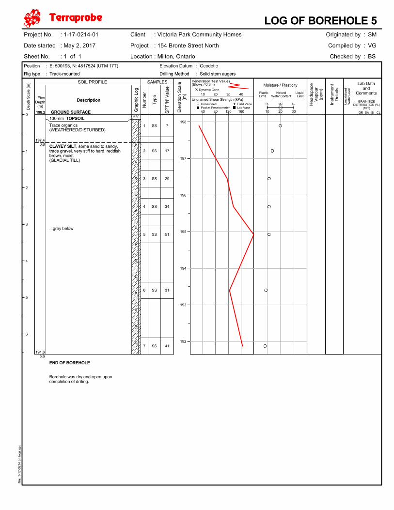
200mm TOPSOIL
Trace organics(WEATHERED/DISTURBED)
CLAYEY SILT, some sand to sandy,trace gravel, very stiff to hard, reddishbrown, moist(GLACIAL TILL)
SANDY SILT, with numerous stonefragments
.
END OF BOREHOLE
Borehole was dry and open uponcompletion of drilling.
19 mm dia. piezometer installed.
1
2
3
4
5
6
7
8 27 44 21
auger grinding
198.30.2
197.70.8
196.22.3
195.82.7
191.96.6
7
16
28
33
42
45
55U
nsta
biliz
edW
ater
Lev
el
198.5
GRAIN SIZEDISTRIBUTION (%)
(MIT)
Gra
phic
Log
Typ
e
Description Unconfined
Num
ber
Ele
vatio
n S
cale
(m)
198
197
196
195
194
193
192
Pocket Penetrometer Field Vane
SOIL PROFILE
GROUND SURFACE
SAMPLES
Dynamic ConeMoisture / Plasticity
10 20 30
PL LLMC
PlasticLimit
NaturalWater Content
LiquidLimit
Hea
dspa
ceV
apou
r(p
pm)
Lab Dataand
Comments
Inst
rum
ent
Det
ails
Dep
th S
cale
(m
)
0
1
2
3
4
5
6
Lab Vane
Undrained Shear Strength (kPa)
40 80 120 160
ElevDepth
(m)
SP
T 'N
' Val
ue
SAGR SI CL
Position : E: 590207, N: 4817513 (UTM 17T) Elevation Datum : Geodetic
LOG OF BOREHOLE 1Originated by :
Compiled by :
Checked by :
SM
VG
BS
Drilling Method : Solid stem augersRig type : Track-mounted
Project No. : 1-17-0214-01
Date started : May 2, 2017
Sheet No. : 1 of 1
Client : Victoria Park Community Homes
Project : 154 Bronte Street North
Location : Milton, Ontario
file
: 1-
17-0
214
bh lo
gs.g
pj
Penetration Test Values(Blows / 0.3m)
10 20 30 40

SS
SS
SS
SS
SS
SS
SS
150mm TOPSOIL
Trace organics(WEATHERED/DISTURBED)
CLAYEY SILT, some sand to sandy,trace gravel, very stiff to hard, reddishbrown, moist(GLACIAL TILL)
...sandy silt
END OF BOREHOLE
Borehole was dry and open uponcompletion of drilling.
1
2
3
4
5
6
7
light auger grinding
198.00.2
197.40.8
191.66.6
8
16
30
50
57
33
65U
nsta
biliz
edW
ater
Lev
el
198.2
GRAIN SIZEDISTRIBUTION (%)
(MIT)
Gra
phic
Log
Typ
e
Description Unconfined
Num
ber
Ele
vatio
n S
cale
(m)
198
197
196
195
194
193
192
Pocket Penetrometer Field Vane
SOIL PROFILE
GROUND SURFACE
SAMPLES
Dynamic ConeMoisture / Plasticity
10 20 30
PL LLMC
PlasticLimit
NaturalWater Content
LiquidLimit
Hea
dspa
ceV
apou
r(p
pm)
Lab Dataand
Comments
Inst
rum
ent
Det
ails
Dep
th S
cale
(m
)
0
1
2
3
4
5
6
Lab Vane
Undrained Shear Strength (kPa)
40 80 120 160
ElevDepth
(m)
SP
T 'N
' Val
ue
SAGR SI CL
Position : E: 590221, N: 4817527 (UTM 17T) Elevation Datum : Geodetic
LOG OF BOREHOLE 2Originated by :
Compiled by :
Checked by :
SM
VG
BS
Drilling Method : Solid stem augersRig type : Track-mounted
Project No. : 1-17-0214-01
Date started : May 2, 2017
Sheet No. : 1 of 1
Client : Victoria Park Community Homes
Project : 154 Bronte Street North
Location : Milton, Ontario
file
: 1-
17-0
214
bh lo
gs.g
pj
Penetration Test Values(Blows / 0.3m)
10 20 30 40

SS
SS
SS
SS
SS
SS
SS
WATER LEVEL READINGSDate Water Depth (m) Elevation (m)
May 10, 2017 1.9 197.0
150mm TOPSOIL
Trace organics(WEATHERED/DISTURBED)
CLAYEY SILT, some sand to sandy,trace gravel, firm to hard, reddish brown,moist(GLACIAL TILL)
END OF BOREHOLE
Borehole was dry and open uponcompletion of drilling.
19 mm dia. piezometer installed.
1
2
3
4
5
6
7
6 23 50 21
auger grinding
198.70.2
198.30.6
192.36.6
7
7
26
38
31
27
43U
nsta
biliz
edW
ater
Lev
el
198.9
GRAIN SIZEDISTRIBUTION (%)
(MIT)
Gra
phic
Log
Typ
e
Description Unconfined
Num
ber
Ele
vatio
n S
cale
(m)
198
197
196
195
194
193
Pocket Penetrometer Field Vane
SOIL PROFILE
GROUND SURFACE
SAMPLES
Dynamic ConeMoisture / Plasticity
10 20 30
PL LLMC
PlasticLimit
NaturalWater Content
LiquidLimit
Hea
dspa
ceV
apou
r(p
pm)
Lab Dataand
Comments
Inst
rum
ent
Det
ails
Dep
th S
cale
(m
)
0
1
2
3
4
5
6
Lab Vane
Undrained Shear Strength (kPa)
40 80 120 160
ElevDepth
(m)
SP
T 'N
' Val
ue
SAGR SI CL
Position : E: 590207, N: 4817541 (UTM 17T) Elevation Datum : Geodetic
LOG OF BOREHOLE 3Originated by :
Compiled by :
Checked by :
SM
VG
BS
Drilling Method : Solid stem augersRig type : Track-mounted
Project No. : 1-17-0214-01
Date started : May 2, 2017
Sheet No. : 1 of 1
Client : Victoria Park Community Homes
Project : 154 Bronte Street North
Location : Milton, Ontario
file
: 1-
17-0
214
bh lo
gs.g
pj
Penetration Test Values(Blows / 0.3m)
10 20 30 40
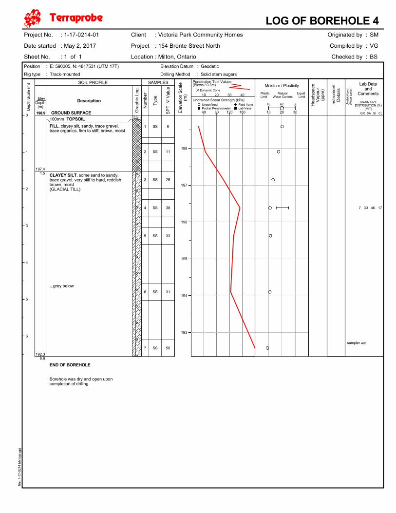
SS
SS
SS
SS
SS
SS
SS
100mm TOPSOIL
FILL, clayey silt, sandy, trace gravel,trace organics, firm to stiff, brown, moist
CLAYEY SILT, some sand to sandy,trace gravel, very stiff to hard, reddishbrown, moist(GLACIAL TILL)
...grey below
END OF BOREHOLE
Borehole was dry and open uponcompletion of drilling.
1
2
3
4
5
6
7
7 30 46 17
sampler wet
197.41.5
192.36.6
6
11
25
38
33
31
50U
nsta
biliz
edW
ater
Lev
el
198.9
GRAIN SIZEDISTRIBUTION (%)
(MIT)
Gra
phic
Log
Typ
e
Description Unconfined
Num
ber
Ele
vatio
n S
cale
(m)
198
197
196
195
194
193
Pocket Penetrometer Field Vane
SOIL PROFILE
GROUND SURFACE
SAMPLES
Dynamic ConeMoisture / Plasticity
10 20 30
PL LLMC
PlasticLimit
NaturalWater Content
LiquidLimit
Hea
dspa
ceV
apou
r(p
pm)
Lab Dataand
Comments
Inst
rum
ent
Det
ails
Dep
th S
cale
(m
)
0
1
2
3
4
5
6
Lab Vane
Undrained Shear Strength (kPa)
40 80 120 160
ElevDepth
(m)
SP
T 'N
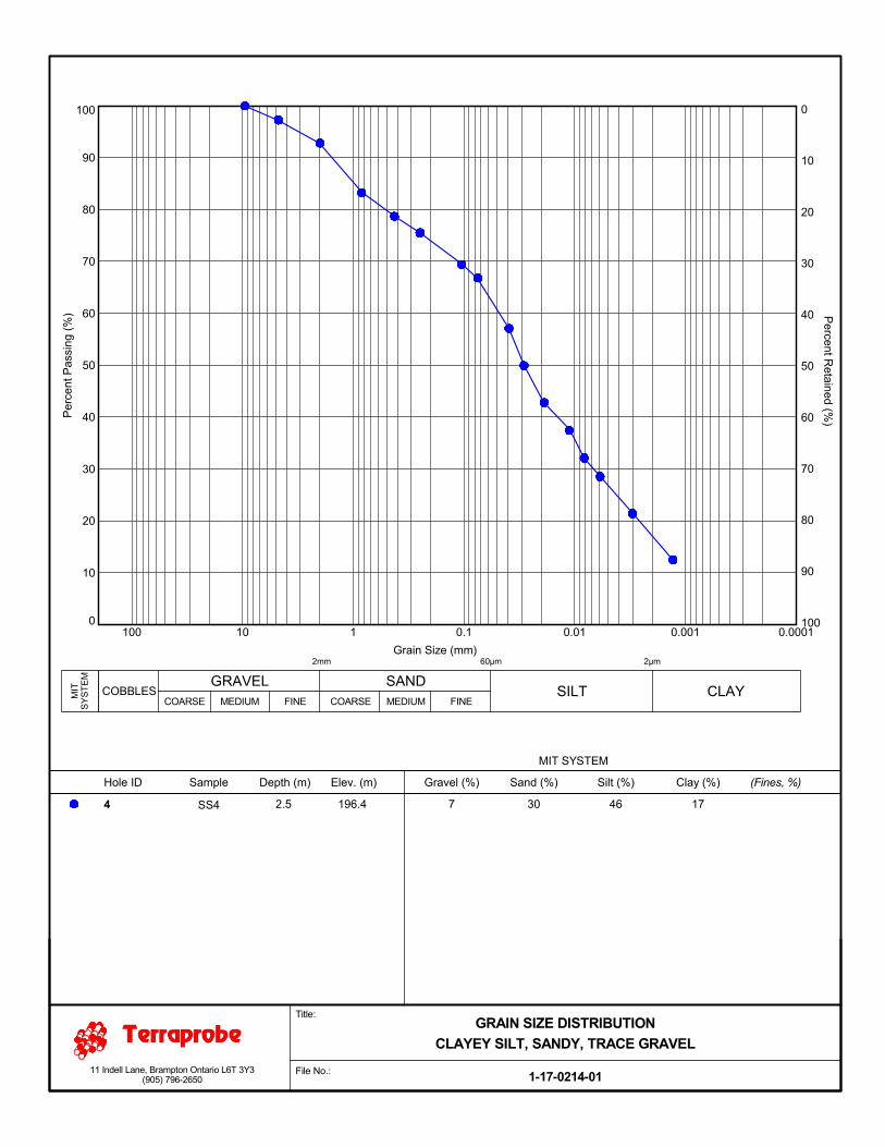
' Val
ue
SAGR SI CL
Position : E: 590205, N: 4817531 (UTM 17T) Elevation Datum : Geodetic
LOG OF BOREHOLE 4Originated by :
Compiled by :
Checked by :
SM
VG
BS
Drilling Method : Solid stem augersRig type : Track-mounted
Project No. : 1-17-0214-01
Date started : May 2, 2017
Sheet No. : 1 of 1
Client : Victoria Park Community Homes
Project : 154 Bronte Street North
Location : Milton, Ontario
file
: 1-
17-0
214
bh lo
gs.g
pj
Penetration Test Values(Blows / 0.3m)
10 20 30 40
SS
SS
SS
SS
SS
SS
SS
130mm TOPSOIL
Trace organics(WEATHERED/DISTURBED)
CLAYEY SILT, some sand to sandy,trace gravel, very stiff to hard, reddishbrown, moist(GLACIAL TILL)
...grey below
END OF BOREHOLE
Borehole was dry and open uponcompletion of drilling.
1
2
3
4
5
6
7
197.40.8
191.66.6
7
17
29
34
51
31
41U
nsta
biliz
edW
ater
Lev
el
198.2
GRAIN SIZEDISTRIBUTION (%)
(MIT)
Gra
phic
Log
Typ
e
Description Unconfined
Num
ber
Ele
vatio
n S
cale
(m)
198
197
196
195
194
193
192
Pocket Penetrometer Field Vane
SOIL PROFILE
GROUND SURFACE
SAMPLES
Dynamic ConeMoisture / Plasticity
10 20 30
PL LLMC
PlasticLimit
NaturalWater Content
LiquidLimit
Hea
dspa
ceV
apou
r(p
pm)
Lab Dataand
Comments
Inst
rum
ent
Det
ails
Dep
th S
cale
(m
)
0
1
2
3
4
5
6
Lab Vane
Undrained Shear Strength (kPa)
40 80 120 160
ElevDepth
(m)
SP
T 'N
' Val
ue
SAGR SI CL
Position : E: 590193, N: 4817524 (UTM 17T) Elevation Datum : Geodetic
LOG OF BOREHOLE 5Originated by :
Compiled by :
Checked by :
SM
VG
BS
Drilling Method : Solid stem augersRig type : Track-mounted
Project No. : 1-17-0214-01
Date started : May 2, 2017
Sheet No. : 1 of 1
Client : Victoria Park Community Homes
Project : 154 Bronte Street North
Location : Milton, Ontario
file
: 1-
17-0
214
bh lo
gs.g
pj
Penetration Test Values(Blows / 0.3m)
10 20 30 40
SIEVE ANDHYDROMETER
ANALYSIS
TERRAPROBE INC.
0
10
20
30
40
50
60
70
80
90
100
0.00010.0010.010.1110100
Percent R
etained (%
)
Grain Size (mm)
0
10
20
30
40
50
60
70
80
90
100
Gravel (%)Depth (m) Elev. (m)
MIT SYSTEM
Sand (%) Silt (%) Clay (%)SampleHole ID
Per
cent
Pas
sing
(%
)
(Fines, %)
SS4 2.5 196.0 8 27 44 211
MIT
SY
ST
EM SAND
CLAYSILT
2µm60µm2mm
COBBLESGRAVEL
COARSE MEDIUM FINE COARSE MEDIUM FINE
Title:
1-17-0214-01File No.:11 Indell Lane, Brampton Ontario L6T 3Y3(905) 796-2650
GRAIN SIZE DISTRIBUTION
CLAYEY SILT, SANDY, TRACE GRAVEL
0
10
20
30
40
50
60
70
80
90
100
0.00010.0010.010.1110100
Percent R
etained (%
)
Grain Size (mm)
0
10
20
30
40
50
60
70
80
90
100
Gravel (%)Depth (m) Elev. (m)
MIT SYSTEM
Sand (%) Silt (%) Clay (%)SampleHole ID
Per
cent
Pas
sing
(%
)
(Fines, %)
SS3 1.8 197.1 6 23 50 213
MIT
SY
ST
EM SAND
CLAYSILT
2µm60µm2mm
COBBLESGRAVEL
COARSE MEDIUM FINE COARSE MEDIUM FINE
Title:
1-17-0214-01File No.:11 Indell Lane, Brampton Ontario L6T 3Y3(905) 796-2650
GRAIN SIZE DISTRIBUTION
CLAYEY SILT, SANDY, TRACE GRAVEL
0
10
20
30
40
50
60
70
80
90
100
0.00010.0010.010.1110100
Percent R
etained (%
)
Grain Size (mm)
0
10
20
30
40
50
60
70
80
90
100
Gravel (%)Depth (m) Elev. (m)
MIT SYSTEM
Sand (%) Silt (%) Clay (%)SampleHole ID
Per
cent
Pas
sing
(%
)
(Fines, %)
SS4 2.5 196.4 7 30 46 174
MIT
SY
ST
EM SAND
CLAYSILT
2µm60µm2mm
COBBLESGRAVEL
COARSE MEDIUM FINE COARSE MEDIUM FINE
Title:
1-17-0214-01File No.:11 Indell Lane, Brampton Ontario L6T 3Y3(905) 796-2650
GRAIN SIZE DISTRIBUTION
CLAYEY SILT, SANDY, TRACE GRAVEL
ATTERBERGLIMITS
TEST RESULTS
TERRAPROBE INC.
0
10
20
30
40
50
60
0 10 20 30 40 50 60 70 80 90 100
MHor
OH
A - Line
Depth (m) Elev. (m)SampleBorehole
Pla
stic
ity In
dex
(PI,
%)
CL
CL
CH
Very High Extremely HighHighLow
Upper Plasticity Range
ML
CL - ML
Liquid Limit (LL, %)
SS4 2.5 196.0 16 SLIGHTLY PLASTIC
MLorOL
1
LL (%) PI (%)
10
DescriptionPL (%)
26
Title:
1-17-0214-01File No.:11 Indell Lane, Brampton Ontario L6T 3Y3(905) 796-2650
ATTERBERG LIMITS CHART

0
10
20
30
40
50
60
0 10 20 30 40 50 60 70 80 90 100
MHor
OH
A - Line
Depth (m) Elev. (m)SampleBorehole
Pla
stic
ity In
dex
(PI,
%)
CL
CL
CH
Very High Extremely HighHighLow
Upper Plasticity Range
ML
CL - ML
Liquid Limit (LL, %)
SS4 2.5 196.4 16 SLIGHTLY PLASTIC
MLorOL
4
LL (%) PI (%)
9
DescriptionPL (%)
25
Title:
1-17-0214-01File No.:11 Indell Lane, Brampton Ontario L6T 3Y3(905) 796-2650
ATTERBERG LIMITS CHART

FIGURES
TERRAPROBE INC.
SITE
SITE
REFERENCE
Microsoft Streets & Trips 2011
FIGURE :Terraprobe11 Indell Lane, Brampton, Ontario, L6T 3Y3
Tel: (905) 796-2650 Fax: (905) 796-2250
Title:
File. No.:
SITE LOCATION PLAN
1-17-0214-01
1
T:\1-P
ro
ject Files\2017\1-17-0214 - 154 B
ro
nte Street, M
ilto
n\01-G
EO
In
vestIg
atio
n\A
. D
wg
s, Lo
gs\A
uto
CA
D\1-17-0214-01 Fig
ure 1 &
2.d
wg
,
Kam
al
BH3
BH2BH1
BH5
BH4
SCALE 1:400
0 10m24
FIGURE :Terraprobe11 Indell Lane, Brampton, Ontario, L6T 3Y3
Tel: (905) 796-2650 Fax: (905) 796-2250
Title:
File No.
BOREHOLE LOCATION PLAN
1-17-0214-01
2
REFERENCE
Victoria Park Community Homes
Sheet Name: Site Plan
Project No.: 117046
Date: June 2017
By: Chamberlain Architect Services Limited
Approximate Borehole Location
LEGEND
T:\1-P
ro
ject Files\2017\1-17-0214 - 154 B
ro
nte Street, M
ilto
n\01-G
EO
In
vestIg
atio
n\A
. D
wg
s, Lo
gs\A
uto
CA
D\1-17-0214-01 Fig
ure 1 &
2.d
wg
,
Kam
al
PAVEMENTDRAINAGE
ALTERNATIVES
TERRAPROBE INC.