Embed Size (px)
Citation preview

Send Orders for Reprints to [email protected]
130 The Open Mechanical Engineering Journal, 2015, 9, 130-140
1874-155X/15 2015 Bentham Open
Open Access
Research on Engine Exhaust Energy Recovery by a Heat Pipe Exchanger with a Semiconductor Thermoelectric Generator Jun Fu*, Yuan Tang, Wei Chen, Yi Ma and Zhiguo Zhu
Department of Mechanical and Energy Engineering, Shaoyang University, Shaoyang 422004, China
Abstract: A heat pipe exchanger was adopted to recover the engine exhaust energy and its internal gas pressure. Velocity and temperature distribution were obtained with the computational fluid dynamics software called ‘FLUENT’. Based on the simulation results, the structure of the exchanger was improved, and its working performance was verified by experiments. The experiments showed that the pressure loss of the exchanger is only about 850 Pa, which has less influence on engine performance and is in good agreement with the simulation, as this is a more homogeneous internal air temperature distribution with better exchanger’s efficiency. And by measuring the output power under the temperatures 335 K, 355 K, 375 K and 395 K, respectively, at the cold end of the semiconductor thermoelectric generator, it was found that it had the same cold end temperature and the temperature difference was over 100 K. The output power increases rapidly at first and then continues to grow but at a decreasing rate, and the largest output power is 75.6 W when the cold end temperature is 335 K with the temperature difference of 380 K, and in addition to this it was observed that under the same temperature difference, the lower cold end temperature is the larger the output power.
Keywords: Exhaust back pressure, exhaust energy, heat pipe exchanger, semiconductor, temperature difference, thermoelectric generator.
1. INTRODUCTION
With the rapid development of automobile industry, the energy consumption of vehicle is increasing very fast, and due to the low thermal efficiency of internal combustion engine, a lot of energy is wasted from the exhaust pipes. Therefore, the vehicle energy saving concept is attracting more and more attention. It has been proved to be strategically significant for energy conservation and emissions reduction to take effective measures to make full use of waste heat from automobile exhausts. At present, the heat pipe technology has been widely studied and used, due to the high thermal efficiency. The heat pipe technology combined with a semiconductor thermoelectric generator device, has been applied to collect the automobile exhaust waste energy and then converted the recovered heat energy into electricity to provide auxiliary power for vehicles. This method will be able to effectively reduce the energy wastage [1, 2]. Thus, a set of heat exchanger have been designed to recovery engine exhaust energy which adopts heat pipe, and the computational fluid dynamics software FLUENT was used to simulate the internal pressure, velocity and temperature fields, and then with the simulation results the geometric design has been improved. Finally, based on the actual bench test to verify exhaust back pressure of a 175 series diesel engine with the heat exchanger installed, the output power of a type of semiconductor thermoelectric generator was measured and
*Address correspondence to this author at the Department of Mechanical and Energy Engineering, Qiliping Campus of Shaoyang University, Shaoyang, Hunan, Postcard: 422004, P.R. China; Tel: +86 15526091134; E-mail: [email protected]
the reasonable matching was researched between the heat pipe device of engine exhaust energy recovery and semiconductor thermoelectric power generator.
2. HEAT EXCHANGER UNIT DESIGN
2.1. Heat Pipe and Heat Exchanger Device
With high heat transfer efficiency and heat conduction ability compared to that of metals, the heat pipe technology has a greater application prospect in the field of heat conduction [3]. Structure of a regular heat pipe is shown in Fig. (1). When the engine’s exhaust energy is collected by the heat pipe, evaporation section at the interior of heat exchanger absorbs the heat, and the capillary’s liquid rapidly evaporates and the vapor flow to the condensation section under the small pressure difference and releases heat to make the medium condense into liquid, so the liquid working medium can flow back to the evaporation side along porous materials by the effect of capillary forces to complete internal hydraulic loop in the heat pipe and heat transport [4].
Fig. (1). The schematic diagram of a heat pipe.
RETRACTED ARTICLE
Research on Engine Exhaust Energy Recovery by a Heat Pipe Exchanger The Open Mechanical Engineering Journal, 2015, Volume 9 131
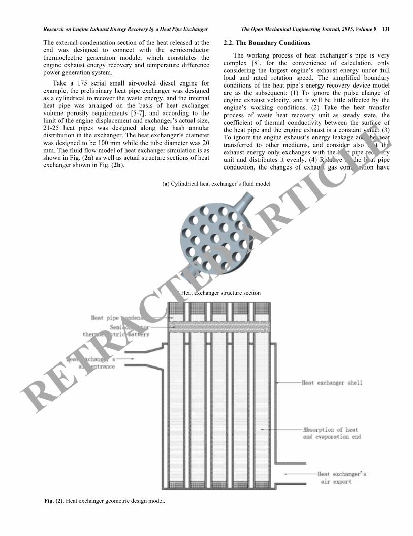
The external condensation section of the heat released at the end was designed to connect with the semiconductor thermoelectric generation module, which constitutes the engine exhaust energy recovery and temperature difference power generation system. Take a 175 serial small air-cooled diesel engine for example, the preliminary heat pipe exchanger was designed as a cylindrical to recover the waste energy, and the internal heat pipe was arranged on the basis of heat exchanger volume porosity requirements [5-7], and according to the limit of the engine displacement and exchanger’s actual size, 21-25 heat pipes was designed along the hash annular distribution in the exchanger. The heat exchanger’s diameter was designed to be 100 mm while the tube diameter was 20 mm. The fluid flow model of heat exchanger simulation is as shown in Fig. (2a) as well as actual structure sections of heat exchanger shown in Fig. (2b).
2.2. The Boundary Conditions
The working process of heat exchanger’s pipe is very complex [8], for the convenience of calculation, only considering the largest engine’s exhaust energy under full load and rated rotation speed. The simplified boundary conditions of the heat pipe’s energy recovery device model are as the subsequent: (1) To ignore the pulse change of engine exhaust velocity, and it will be little affected by the engine’s working conditions. (2) Take the heat transfer process of waste heat recovery unit as steady state, the coefficient of thermal conductivity between the surface of the heat pipe and the engine exhaust is a constant value. (3) To ignore the engine exhaust’s energy leakage and the heat transferred to other mediums, and consider also that the exhaust energy only exchanges with the heat pipe recovery unit and distributes it evenly. (4) Relative to the heat pipe conduction, the changes of exhaust gas composition have
(a) Cylindrical heat exchanger’s fluid model
(b) Heat exchanger structure section
Fig. (2). Heat exchanger geometric design model.
RETRACTED ARTICLE

132 The Open Mechanical Engineering Journal, 2015, Volume 9 Fu et al.
fewer effects on the calculation error [9], so the calculation process ignores the engine exhaust air density difference and specific heat capacity changes with temperature volatility. Inlet parameters in the simulation model are inlet temperature and velocity of heat fluid which are absorbed into the heat pipe exchanger, whose specific values could be obtained by actual measurements. In this experiment the inlet gas temperature was set to about 675 K according to the experiments under the rated rotate speed and full load. The specific values of outlet parameters could be determined by the quality of energy and momentum conservation equation [10] and calculated automatically by the software. The heat pipe exchanger was adopted for energy recovery, so it needed to add the energy equation in the simulation process, and for the distribution of heat pipes, the exhaust gas flow would be affected and produce turbulence, so the standard k-ε turbulence model was adopted in the simulation process. The thermal conductivity coefficient of heat pipe had isotropic properties, and the circumferential thermal conduc-tivity coefficient was set as 385 W/(m·K), while the axial thermal conductivity was determined by the experiments. Among them, the heat conduction coefficient of the evaporation section’s bottom and finned condensation was set as 205 W/(m·K), and for the heat loss of the exchanger’s outer wall being smaller than the heat pipe’s, it was set as adiabatic [11]. The tetrahedron and the wedge grids were adopted in the calculation, which could meet the require-ments of computation [12].
2.3. Simulation Results
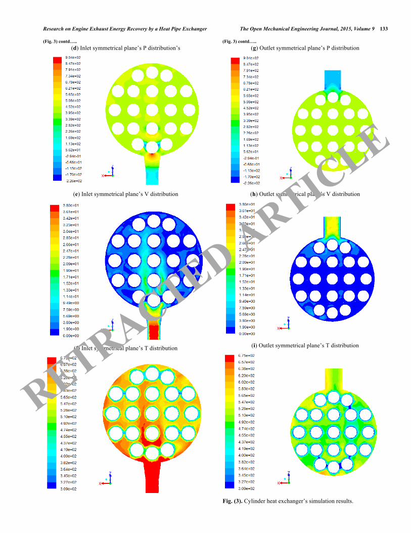
According to the above settings and boundary conditions simplifying, the computational fluid dynamics software FLUENT was used to calculate the internal fluid’s pressure (P), velocity (V) and temperature (T) of the cylindrical heat exchanger, whose contours are as shown in Fig. (3), where (a-c) are the P, V and T distribution of the inlet and outlet symmetry plane respectively, (d-f) are the inlet symmetrical plane, (g-i) are the outlet symmetrical plane’s. From the above pictures of (a), (d) and (g), it can be seen that the pressure loss of the air flow through the heat exchanger device is 900-930 Pa. This device is not cond-uctive enough for the exhaust gas to overcome the atmos-pheric pressure when it is discharging. At the same time, it is known in (b), (e) and (h) that inlet area’s air flow velocity in the heat exchanger can be up to 30-36 m/s, but the outlet’s is reduced to 20 to 25 m/s and high-speed airflow mainly distributes near the entrance of the center axis. Meanwhile, it can be seen that the center of inlet temperature is higher in (c), (f) and (i), which reaches 650-675 K while the outlet temperature is nearly 475-500 K and the average temperature is around 530 K near the edges. And because the time consumption in the heat pipe energy transfer process is shorter than that of the engine exhaust gas flows through the areas [12, 13], the edge area’s air flow with low speed is not conducive enough for the heat pipe to lower the temperature of the high temperature gas, which slow down the heat exchange rate and reduce the thermal efficiency. Based on the above simulation results, improvement to the cylindrical heat exchanger’s geometry is considered to
(a) P distribution of symmetry plane’s
(b) V distribution of symmetry plane’s
(c) T distribution of symmetry plane’s
RETRACTED ARTICLE
Research on Engine Exhaust Energy Recovery by a Heat Pipe Exchanger The Open Mechanical Engineering Journal, 2015, Volume 9 133
(Fig. 3) contd….. (d) Inlet symmetrical plane’s P distribution’s
(e) Inlet symmetrical plane’s V distribution
(f) Inlet symmetrical plane’s T distribution
(Fig. 3) contd….. (g) Outlet symmetrical plane’s P distribution
(h) Outlet symmetrical plane’s V distribution
(i) Outlet symmetrical plane’s T distribution
Fig. (3). Cylinder heat exchanger’s simulation results.
RETRACTED ARTICLE

134 The Open Mechanical Engineering Journal, 2015, Volume 9 Fu et al.
cut off the parts of the slower velocity flow and the poorer heat transfer performance. The remaining shape approxi-mates to a cuboid or a cube, and is considered as a shape for a heat exchanger. The basic framework and heat pipe were all arranged and designed on the basis of the cylindrical exchanger. The heat pipe diameter was also designed as 20 mm, the 3D modeling for fluid simulation are as shown in Fig. (4a, b) respectively.
(a) Cubes heat exchanger 3D model for fluid simulation
(b) Cuboid heat exchanger 3D model for fluid simulation
Fig. (4). Improved heat exchanger 3D model for fluid simulation.
Such as the cylindrical heat exchanger’s parameters setting and calculate, the fluid simulation results of cubic heat exchanger are as shown in Fig. (5). From Fig. (5a, d, g), can be seen that the pressure loss of the fluid through the heat exchanger is 850-880 Pa, which is about 50 Pa less than cylindrical exchanger, and the pressure distribution is more uniform along the heat exchanger’s symmetric surface. As shown in Fig. (5b, e, h), the high-speed air flow can pass through a longer distance in the heat exchanger, which covers the entrance area around the central axis. The inlet velocity reaches 35 to 38 m/s and the outlet velocity reaches to 26-30 m/s, which is good for the heat exchange between the heat pipe and engine exhaust and promotes the efficiency improvement of the heat pipe. It can also be seen from Fig. (5c, f) and (i) that the inlet temperature is about 650-650 K while the outlet temperature is decreased by 380-400 K. This suggests that the heat pipes have absorbed more energy. The fluid simulation results of improved cuboid heat exchanger are shown in Fig. (6).
(a) P distribution of symmetry plane’s
(b) V distribution of symmetry plane’s
(c) T distribution of symmetry plane’s
RETRACTED ARTICLE

Research on Engine Exhaust Energy Recovery by a Heat Pipe Exchanger The Open Mechanical Engineering Journal, 2015, Volume 9 135
(Fig. 5) contd….. (d) Inlet symmetrical plane’s P distribution
(e) Inlet symmetrical plane’s V distribution
(f) Inlet symmetrical plane’s T distribution
(Fig. 5) contd….. (g) Outlet symmetrical plane’s P distribution
(h) Outlet symmetrical plane’s V distribution
(i) Outlet symmetrical plane’s T distribution
Fig. (5). The improved cubes heat exchanger fluid model simulation results.
RETRACTED ARTICLE
136 The Open Mechanical Engineering Journal, 2015, Volume 9 Fu et al.
(a) P distribution of symmetry plane’s
(b) V distribution of symmetry plane’s
(c) T distribution of symmetry plane’s
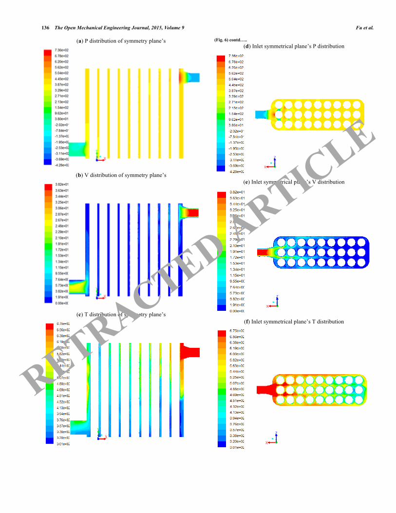
(Fig. 6) contd….. (d) Inlet symmetrical plane’s P distribution
(e) Inlet symmetrical plane’s V distribution
(f) Inlet symmetrical plane’s T distribution
RETRACTED ARTICLE

Research on Engine Exhaust Energy Recovery by a Heat Pipe Exchanger The Open Mechanical Engineering Journal, 2015, Volume 9 137
(Fig. 6) contd….. (g) Outlet symmetrical plane’s P distribution
(h) Outlet symmetrical plane’s V distribution
(i) Outlet symmetrical plane’s T distribution
Fig. (6). The improved cuboid heat exchanger fluid model simulation results.
In the same way, on the basis of contours analysis above, the inlet and outlet pressure difference of the cuboid heat exchanger reaches to 890-920 Pa, and the high pressure and high velocity fluids are mainly distributed near the inlet areas. The velocity reaches to 28-32 m/s while in the outlet zone it reduces to 17-20 m/s. Further away from the inlet, the flow velocity reduces faster and even decreases by 2-4 m/s, which is insufficient for the exchanger’s efficient perfor-mance. Moreover, the temperature distribution is also inter-nally uneven of the heat exchanger from the inlet to the remote area, and in some position away from the inlet the temperature reduces to 450-470 K, while in the cross section area of the outlet the temperature decreases by 320-340 K and at low temperatures gas’s density is higher than that at high temperatures with the same volume, which is not conducive enough to discharge the exhaust gas in this area.
3. PERFORMANCE EXPERIMENT OF HEAT EXCHANGER
The simulation results showed that, in the cubic heat pipe exchanger, the internal flow resistance was smaller than in the cylindrical exchanger, and pressure difference smaller at the inlet and outlet of heat exchanger, which is beneficial to engine’s normal exhaust, and for the smaller internal fluid velocity fluctuation, it was advantageous to the heat pipe’s energy exchange, with the high temperature exhaust gas. Far away from the inlet of the cuboid heat exchanger, the temperature and the velocity of the distribution were relatively uniform, which was not conducive to the heat transfer in this area, thereby the overall thermal efficiency of the heat exchanger would be reduced. Therefore, a cubic heat exchanger was chosen to measure the impact on the exhaust resistance, and a type of semiconductor thermoelectric generator module was adopted to verify its efficiency of power generation. Among them, the exhaust resistance and experimental data of output power were processed by the method mentioned in the reference [13].
3.1. Exhaust Resistance Test
In order to verify the actual exhaust resistance in the cubic heat exchanger, the heat pipe exchanger and semiconductor thermoelectric generator on the engine test bench, were assembled to measure the pressure difference between the inlet and the outlet. Based on the automatic control system for the engine, the real-time monitor and storage of the data was carried out, such as the diesel engine’s power, rotational speed and torque, fuel temperature and fuel consumption parameters. Before formal experiment, according to the simulation results, some different engine loads were selected at random, the inlet’s pressure difference was tested to determine the measurement range of the pressure gauge. The results showed that the pressure difference was close to the simulation and installing a range of 1.5 kPa pressure gauge could meet the experimental requirements. The engine’s test bench is shown in Fig. (7).
RETRACTED ARTICLE

138 The Open Mechanical Engineering Journal, 2015, Volume 9 Fu et al.
1. Test bench bed 2. Hydraulic pressure gauge 3. Control signal input lines 4. Torque signal lines 5. Hydraulic dynamometer 6. Temperature sensor 7. Water level sensor 8. Exhaust temperature sensor signal lines 9. Exhaust pipe 10. Oil temperature signal lines 11. Cooling fan dome 12. Engine 13. Fuel flow signal lines 14. Fuel consumption instrument 15. Pipeline 16. Air filter 17. Coupling 18. Speed sensor 19. FC2000 Control box 20. Connecting wire
Fig. (7). Engine test bench.
Under the same rotate speed and same load respectively, the pressure difference’s variation at the inlet and outlet of heat exchanger are shown in Fig. (8a, b).
(a) Curves of pressure differential vs the load
(b) Curves of pressure differential vs the speed
Fig. (8). Heat exchanger pressure differential’s variation with engine load or speed.
From the Fig. (8), it can be seen that the pressure difference at the inlet and outlet of the heat pipe exchanger increases as the linear trend with the engine load increasing.
Under the rotational speed of 2600 r/min and a full load, the pressure difference reaches 870-880 Pa. However, the linear proportional coefficients of the pressure difference are relatively close with the engine’s load increasing, which is because the quantity of fresh charge increases, which leads to the mass flow increase of the emissions as well as the resistance increases in the heat pipe when the gas flows through the same volume of heat exchanger. While under the same load, with the engine’s rotating speed increasing, the increase of amplitude of pressure difference at the inlet and outlet of the heat exchanger is larger.
3.2. Semiconductor Thermoelectric Generator Module Experiment
The experimental platform of the semiconductor thermoelectric generator includes a series of semiconductor thermoelectric cells, an air-cooled radiator, high precision digital multi-meter, thermocouple and a test circuit and so on. To ensure a good thermal contact between the semicond-uctor thermoelectric module and the thermal conductivity copper of the heat pipe, some silicone grease with good thermal conductivity was coated on the heat pipe and the battery contact surface. The individual semiconductor thermoelectric generator module adopted in the experiment is as shown in Fig. (9).
Fig. (9). Individual. Individual module diagram of semiconductor thermoelectric generator.
The electromotive force ε of semiconductor thermoelectric battery is proportional to the temperature difference △T of the hot and cold end [14], so the test circuit of volt-ampere characteristic with the matched electro-load is adopted to study the relationship between the maximum output power and temperature difference. In order to control the engine load and change the contact temperature between the output of heat exchanger and the hot end of the semiconductor thermoelectric cell when the cold end’s temperature was 335 K, 355 K, 375 K and 395 K respectively, the curves between the output power of the electro-loads and the temperature difference of the hot and cold end are as shown in Fig. (10). From the Fig. (10), it can be seen that when temperature difference is less than 100 K, the output power is relatively
RETRACTED ARTICLE

Research on Engine Exhaust Energy Recovery by a Heat Pipe Exchanger The Open Mechanical Engineering Journal, 2015, Volume 9 139
smaller, which is almost not affected by the temperature change of the cold end which is less than 10 W. When it is greater than 100 K, under the same temperature at the cold end, the power output shows a trend that it firstly increases rapidly and then the increase rate reduces. Among them, when the temperature is 335 K at the cold end and the temperature difference reaches 380 K between the cold and the hot end, the power consumption is at its largest at 75.6 W. However there is a greater output power under the same temperature difference, over 100 K, with a lower temperature at the cold end, and with the larger temperature difference, the increasing rate of output power at the cold end with higher temperature is faster.
Fig. (10). The matching curves of load power output vs different T difference at different cold end T.
CONCLUSION
High heat efficiency of heat pipe device to collect the waste energy of engine exhaust and recycling the energy into electrical energy by semiconductor thermoelectric generation module has a great significance on energy recycling for the vehicles. (1) Through the internal flow field simulation of the heat
exchanger, it can be found that using cubic heat exchanger, the arranged heat pipe causes less pressure loss and more uniform distribution of velocity and temperature, which can improve the efficiency of heat exchanger and have a minimum effect on engine’s performance.
(2) The performance test results of a 175 serial diesel engine with the cubic heat exchanger, shows that under the rated rotating speed and full load, the pressure difference between the outlet and inlet of heat exchanger is largest, i.e. 850 Pa, which matches the simulation value, and for small exhaust resistance there is less influence on the engine working performance.
(3) The results from experiments on a type of semiconductor thermoelectric generator module on the heat pipe exchanger, shows that, under the same temperature difference of the hot and cold end, with the lower temperature at the cold end, the output
power would greater, and under the same temperature at the cold end, with the temperature difference increasing at the hot and cold end, the output power increases quickly at first and then the growth rate decreases gradually.
CONFLICT OF INTEREST
The authors confirm that this article content has no conflict of interest.
ACKNOWLEDGEMENTS
This project are supported by the Innovation Platform Open Foundation in Higher Educational Institutions of Hunan Province (ID:12K130), the Aid Program for Science and Technology Innovative Research Team in Higher Educational Institutions of Hunan Province, and the Postgraduate Innovative Research Project of Shaoyang University.
REFERENCES
[1] B. Liu, and H. Liang, "Research status and development trends of engine waste heat recovery technology", Small Internal Combustion Engine and Motorcycle, vol. 40, pp. 93-96, April 2011.
[2] J. Ma, X. Lu, and Q. Zheng, "Comparative analysis of technology of waste heat recovery systems of engine", Tractor& Farm Transporter, vol. 39, pp. 33-36, October 2013.
[3] M. He, X. Zhang, and K. Zeng, "A new combined thermodynamic cycle for waste heat recovery of vehicle engine", Journal of Xi’an Jiaotong University, vol.43, no. 99, pp.1-5, November 2009.
[4] S. Sun, and H. Zhang, "Numerical simulation of thermal performance and temperature field in heat pipe heat exchanger", CIESC Journal, vol. 55, pp. 472-475, March 2004.
[5] Y. Li, "The Research of Temperature Difference Power Generation Based on the Automobile Tail Gas Waste Heat Recovery", Ph. D. thesis, University of electronic science and technology of China, Chengdu, Sichuan province, Chian, May 26, 2007.
[6] T. Samana, T. Kiatsiriroat, and A. Nuntaphan, "Enhancement of fin efficiency of a solid wire fin by oscillating heat pipe under forced convection", Case Studies in Thermal Engineering, vol. 2, pp. 36-41, 2014.
[7] H. Lu, T. Wu, S. Bai, K. Xu, Y. Huang, W. Gao, X. Yin, and L. Chen, "Experiment on thermal uniformity and pressure drop of exhaust heat exchanger for automotive thermoelectric generator", Energy, vol. 54, pp. 372-377, 2013.
[8] W. SUN, Numerical Simulation and Experimental Study on Heat Pipe Radiator for Electronic Element, Ph. D. thesis, Zhejiang University, Hangzhou, Zhejiang province, 2003.
[9] J. Fu, and J. Liu, Z. Xu, C. Ren, and B. Deng, "A combined thermodynamic cycle based on methanol dissociation for IC (internal combustion) engine exhaust heat recovery", Energy, vol .55, pp. 778-786, 2013.
[10] S. Zhu, K. Deng, and S. Qu, "Energy and exergy analyses of a bottoming Rankine cycle for engine exhaust heat recovery", Energy, vol. 58, pp. 448-457, 2013.
[11] G. Wu, L. Cao, P. Huang, and B. San, "Research of experiment verification and simulation for heat pipe cooling of t/r subassembly of radar on warship", Journal of Wuhan University of Technology (Transportation Science & Engineering), vol. 33, no. 3, pp. 475-478, June 2009.
[12] F.J. Salvador, J. Martínez-López, M. Caballer, and C. De Alfonso, "Study of the influence of the needle lift on the internal flow and cavitation phenomenon in diesel injector nozzles by CFD using RANS methods", Energy Conversion and Management, vol. 66, pp. 246-256, 2013.
RETRACTED ARTICLE

140 The Open Mechanical Engineering Journal, 2015, Volume 9 Fu et al.
[13] J. Fu, J. Gong, W. Yuan, B. Wang, and W. Chen, "Establishment and application of MAP for regeneration back-pressure threshold value of diesel particulate filter", Transactions of the Chinese Society of Agricultural Engineering (Transactions of the CSAE), vol. 29, pp. 47-56, December 2013.
[14] Z. Bai, Research on Thermal Systems of Semiconductor Thermoelectric generator in Middle-High Temperature Waste Heat Recovery. Nanjing University of Aeronautics and Astronautics: Nanjing, Jiangsu Province 2009.
Received: January 8, 2015 Revised: January 15, 2015 Accepted: January 16, 2015 © Fu et al.; Licensee Bentham Open.
This is an open access article licensed under the terms of the Creative Commons Attribution Non-Commercial License (http://creativecommons.org/licenses/by-nc/3.0/) which permits unrestricted, non-commercial use, distribution and reproduction in any medium, provided the work is properly cited.
RETRACTED ARTICLE